JP2019053003A - Data processor, method for processing data, and data processing program - Google Patents
Data processor, method for processing data, and data processing program Download PDFInfo
- Publication number
- JP2019053003A JP2019053003A JP2017178831A JP2017178831A JP2019053003A JP 2019053003 A JP2019053003 A JP 2019053003A JP 2017178831 A JP2017178831 A JP 2017178831A JP 2017178831 A JP2017178831 A JP 2017178831A JP 2019053003 A JP2019053003 A JP 2019053003A
- Authority
- JP
- Japan
- Prior art keywords
- uav
- coordinate system
- laser
- data
- targets
- Prior art date
- Legal status (The legal status is an assumption and is not a legal conclusion. Google has not performed a legal analysis and makes no representation as to the accuracy of the status listed.)
- Granted
Links
- 238000012545 processing Methods 0.000 title claims description 54
- 238000000034 method Methods 0.000 title abstract description 58
- 238000004364 calculation method Methods 0.000 claims description 34
- 230000001678 irradiating effect Effects 0.000 claims description 8
- 230000006870 function Effects 0.000 description 31
- 238000005259 measurement Methods 0.000 description 27
- 238000006243 chemical reaction Methods 0.000 description 18
- 238000004891 communication Methods 0.000 description 18
- 230000008569 process Effects 0.000 description 18
- 230000003287 optical effect Effects 0.000 description 17
- 239000011159 matrix material Substances 0.000 description 11
- 230000008859 change Effects 0.000 description 9
- 230000004048 modification Effects 0.000 description 7
- 238000012986 modification Methods 0.000 description 7
- 238000001514 detection method Methods 0.000 description 6
- 238000013519 translation Methods 0.000 description 5
- 238000010586 diagram Methods 0.000 description 4
- 238000013500 data storage Methods 0.000 description 3
- 239000011521 glass Substances 0.000 description 2
- 230000007246 mechanism Effects 0.000 description 2
- 230000035945 sensitivity Effects 0.000 description 2
- RZVHIXYEVGDQDX-UHFFFAOYSA-N 9,10-anthraquinone Chemical compound C1=CC=C2C(=O)C3=CC=CC=C3C(=O)C2=C1 RZVHIXYEVGDQDX-UHFFFAOYSA-N 0.000 description 1
- 238000004458 analytical method Methods 0.000 description 1
- 230000008901 benefit Effects 0.000 description 1
- 239000003086 colorant Substances 0.000 description 1
- 230000007423 decrease Effects 0.000 description 1
- 230000000694 effects Effects 0.000 description 1
- 238000005516 engineering process Methods 0.000 description 1
- 230000005484 gravity Effects 0.000 description 1
- 238000009434 installation Methods 0.000 description 1
- 230000010354 integration Effects 0.000 description 1
- 238000000691 measurement method Methods 0.000 description 1
- 239000002184 metal Substances 0.000 description 1
- 230000010355 oscillation Effects 0.000 description 1
- 238000010422 painting Methods 0.000 description 1
- 238000012805 post-processing Methods 0.000 description 1
- 238000003672 processing method Methods 0.000 description 1
- 238000001228 spectrum Methods 0.000 description 1
- 238000004381 surface treatment Methods 0.000 description 1
- 230000009466 transformation Effects 0.000 description 1
- 239000013585 weight reducing agent Substances 0.000 description 1
Images


Classifications
-
- G—PHYSICS
- G01—MEASURING; TESTING
- G01S—RADIO DIRECTION-FINDING; RADIO NAVIGATION; DETERMINING DISTANCE OR VELOCITY BY USE OF RADIO WAVES; LOCATING OR PRESENCE-DETECTING BY USE OF THE REFLECTION OR RERADIATION OF RADIO WAVES; ANALOGOUS ARRANGEMENTS USING OTHER WAVES
- G01S17/00—Systems using the reflection or reradiation of electromagnetic waves other than radio waves, e.g. lidar systems
- G01S17/88—Lidar systems specially adapted for specific applications
- G01S17/93—Lidar systems specially adapted for specific applications for anti-collision purposes
- G01S17/933—Lidar systems specially adapted for specific applications for anti-collision purposes of aircraft or spacecraft
-
- G—PHYSICS
- G01—MEASURING; TESTING
- G01S—RADIO DIRECTION-FINDING; RADIO NAVIGATION; DETERMINING DISTANCE OR VELOCITY BY USE OF RADIO WAVES; LOCATING OR PRESENCE-DETECTING BY USE OF THE REFLECTION OR RERADIATION OF RADIO WAVES; ANALOGOUS ARRANGEMENTS USING OTHER WAVES
- G01S17/00—Systems using the reflection or reradiation of electromagnetic waves other than radio waves, e.g. lidar systems
- G01S17/02—Systems using the reflection of electromagnetic waves other than radio waves
- G01S17/06—Systems determining position data of a target
- G01S17/42—Simultaneous measurement of distance and other co-ordinates
-
- G—PHYSICS
- G01—MEASURING; TESTING
- G01S—RADIO DIRECTION-FINDING; RADIO NAVIGATION; DETERMINING DISTANCE OR VELOCITY BY USE OF RADIO WAVES; LOCATING OR PRESENCE-DETECTING BY USE OF THE REFLECTION OR RERADIATION OF RADIO WAVES; ANALOGOUS ARRANGEMENTS USING OTHER WAVES
- G01S17/00—Systems using the reflection or reradiation of electromagnetic waves other than radio waves, e.g. lidar systems
- G01S17/66—Tracking systems using electromagnetic waves other than radio waves
-
- G—PHYSICS
- G01—MEASURING; TESTING
- G01S—RADIO DIRECTION-FINDING; RADIO NAVIGATION; DETERMINING DISTANCE OR VELOCITY BY USE OF RADIO WAVES; LOCATING OR PRESENCE-DETECTING BY USE OF THE REFLECTION OR RERADIATION OF RADIO WAVES; ANALOGOUS ARRANGEMENTS USING OTHER WAVES
- G01S17/00—Systems using the reflection or reradiation of electromagnetic waves other than radio waves, e.g. lidar systems
- G01S17/86—Combinations of lidar systems with systems other than lidar, radar or sonar, e.g. with direction finders
-
- G—PHYSICS
- G01—MEASURING; TESTING
- G01S—RADIO DIRECTION-FINDING; RADIO NAVIGATION; DETERMINING DISTANCE OR VELOCITY BY USE OF RADIO WAVES; LOCATING OR PRESENCE-DETECTING BY USE OF THE REFLECTION OR RERADIATION OF RADIO WAVES; ANALOGOUS ARRANGEMENTS USING OTHER WAVES
- G01S7/00—Details of systems according to groups G01S13/00, G01S15/00, G01S17/00
- G01S7/48—Details of systems according to groups G01S13/00, G01S15/00, G01S17/00 of systems according to group G01S17/00
- G01S7/481—Constructional features, e.g. arrangements of optical elements
- G01S7/4817—Constructional features, e.g. arrangements of optical elements relating to scanning
-
- G—PHYSICS
- G08—SIGNALLING
- G08G—TRAFFIC CONTROL SYSTEMS
- G08G5/00—Traffic control systems for aircraft, e.g. air-traffic control [ATC]
- G08G5/0017—Arrangements for implementing traffic-related aircraft activities, e.g. arrangements for generating, displaying, acquiring or managing traffic information
- G08G5/0026—Arrangements for implementing traffic-related aircraft activities, e.g. arrangements for generating, displaying, acquiring or managing traffic information located on the ground
-
- G—PHYSICS
- G08—SIGNALLING
- G08G—TRAFFIC CONTROL SYSTEMS
- G08G5/00—Traffic control systems for aircraft, e.g. air-traffic control [ATC]
- G08G5/0047—Navigation or guidance aids for a single aircraft
- G08G5/0069—Navigation or guidance aids for a single aircraft specially adapted for an unmanned aircraft
-
- G—PHYSICS
- G08—SIGNALLING
- G08G—TRAFFIC CONTROL SYSTEMS
- G08G5/00—Traffic control systems for aircraft, e.g. air-traffic control [ATC]
- G08G5/0073—Surveillance aids
- G08G5/0082—Surveillance aids for monitoring traffic from a ground station
-
- B—PERFORMING OPERATIONS; TRANSPORTING
- B64—AIRCRAFT; AVIATION; COSMONAUTICS
- B64C—AEROPLANES; HELICOPTERS
- B64C39/00—Aircraft not otherwise provided for
- B64C39/02—Aircraft not otherwise provided for characterised by special use
- B64C39/024—Aircraft not otherwise provided for characterised by special use of the remote controlled vehicle type, i.e. RPV
-
- B—PERFORMING OPERATIONS; TRANSPORTING
- B64—AIRCRAFT; AVIATION; COSMONAUTICS
- B64U—UNMANNED AERIAL VEHICLES [UAV]; EQUIPMENT THEREFOR
- B64U2101/00—UAVs specially adapted for particular uses or applications
- B64U2101/30—UAVs specially adapted for particular uses or applications for imaging, photography or videography
-
- B—PERFORMING OPERATIONS; TRANSPORTING
- B64—AIRCRAFT; AVIATION; COSMONAUTICS
- B64U—UNMANNED AERIAL VEHICLES [UAV]; EQUIPMENT THEREFOR
- B64U2201/00—UAVs characterised by their flight controls
-
- B—PERFORMING OPERATIONS; TRANSPORTING
- B64—AIRCRAFT; AVIATION; COSMONAUTICS
- B64U—UNMANNED AERIAL VEHICLES [UAV]; EQUIPMENT THEREFOR
- B64U2201/00—UAVs characterised by their flight controls
- B64U2201/10—UAVs characterised by their flight controls autonomous, i.e. by navigating independently from ground or air stations, e.g. by using inertial navigation systems [INS]
- B64U2201/104—UAVs characterised by their flight controls autonomous, i.e. by navigating independently from ground or air stations, e.g. by using inertial navigation systems [INS] using satellite radio beacon positioning systems, e.g. GPS
Landscapes
- Engineering & Computer Science (AREA)
- Physics & Mathematics (AREA)
- General Physics & Mathematics (AREA)
- Radar, Positioning & Navigation (AREA)
- Remote Sensing (AREA)
- Electromagnetism (AREA)
- Computer Networks & Wireless Communication (AREA)
- Aviation & Aerospace Engineering (AREA)
- Optical Radar Systems And Details Thereof (AREA)
- Length Measuring Devices By Optical Means (AREA)
Abstract
Description
本発明は、航空機の姿勢を計測する技術に関する。 The present invention relates to a technique for measuring the attitude of an aircraft.
UAV(Unmanned Aerial Vehicle)(無人航空機)等の航空機からレーザースキャンを行う場合、当該航空機航の位置と姿勢の情報が重要となる。これは、UAVを用いた航空写真測量においても同じである。精密な姿勢の情報は、高精度の慣性計測装置(IMU(Inertial Measurement Unit))を用いれば得られる(例えば、特許文献1を参照)。しかしながら、高精度のIMUは、高価、大型、高重量である。UAVは、低コストで運用できるのが強みであるが、搭載機器の容積および搭載機器の重量が限定される。この点で、UAVの姿勢の計測を上記の高精度のIMUで行うことは適切でない。 When laser scanning is performed from an aircraft such as a UAV (Unmanned Aerial Vehicle) (unmanned aerial vehicle), information on the position and orientation of the aircraft navigation is important. The same applies to aerial photogrammetry using UAV. Precise posture information can be obtained by using a high-precision inertial measurement device (IMU (Inertial Measurement Unit)) (see, for example, Patent Document 1). However, a high-precision IMU is expensive, large, and heavy. UAV has the advantage that it can be operated at low cost, but the volume of the mounted device and the weight of the mounted device are limited. In this respect, it is not appropriate to measure the UAV posture with the above-described high-precision IMU.
本発明は、IMUを用いる以外の方法で航空機の姿勢を計測できる技術の提供を目的とする。 An object of this invention is to provide the technique which can measure the attitude | position of an aircraft by methods other than using IMU.
請求項1に記載の発明は、飛行する航空機に第1の座標系に固定されたレーザースキャナからレーザースキャン光を照射することで得られたレーザースキャンデータを取得するレーザースキャンデータ取得部と、前記レーザースキャンデータに基づき、前記飛行する前記航空機の前記第1の座標系での姿勢を算出する姿勢算出部とを備え、前記姿勢は、前記レーザースキャンデータに基づき特定された前記航空機における複数の位置に基づいて算出されるデータ処理装置である。
The invention according to
請求項2に記載の発明は、請求項1に記載の発明において、前記航空機は識別可能な複数のターゲットを備え、前記レーザースキャンデータは、前記航空機が備えた識別可能な複数のターゲットを対象としたレーザースキャンにより得られることを特徴とする。
The invention according to
請求項3に記載の発明は、請求項2に記載の発明において、前記複数のターゲットの識別がターゲットの大きさの違いに基づいて行われることを特徴とする。請求項4に記載の発明は、請求項2または3に記載の発明において、前記複数のターゲットは曲面の反射面を有し、前記複数のターゲットの識別が前記曲面の曲率半径の違いに基づいて行われることを特徴とする。
According to a third aspect of the present invention, in the second aspect of the present invention, the plurality of targets are identified based on a difference in target size. The invention according to claim 4 is the invention according to
請求項5に記載の発明は、請求項2〜4のいずれか一項に記載の発明において、前記複数のターゲットの位置の特定が前記曲面の曲率中心を求めることで行われることを特徴とする。請求項6に記載の発明は、請求項2〜5のいずれか一項に記載の発明において、前記複数のターゲットの識別がターゲット表面の色の違いに基づいて行われることを特徴とする。 According to a fifth aspect of the invention, in the invention according to any one of the second to fourth aspects, the position of the plurality of targets is specified by obtaining a curvature center of the curved surface. . According to a sixth aspect of the present invention, in the invention according to any one of the second to fifth aspects, the plurality of targets are identified based on a difference in color of the target surface.
請求項7に記載の発明は、請求項2〜6のいずれか一項に記載の発明において、前記第1の座標系における前記航空機の位置のデータを取得する位置データ取得部によって取得される前記航空機の位置に基づき、前記複数のターゲットに含まれる2以上のターゲットが含まれる範囲をレーザースキャン範囲として設定するスキャン範囲設定部を備えることを特徴とする。 Invention of Claim 7 is acquired by the position data acquisition part which acquires the data of the position of the said aircraft in the said 1st coordinate system in the invention as described in any one of Claims 2-6. A scan range setting unit is provided that sets, as a laser scan range, a range including two or more targets included in the plurality of targets based on the position of the aircraft.
請求項8に記載の発明は、請求項2〜7のいずれか一項に記載の発明において、前記第1の座標系における前記航空機の位置のデータを取得する位置データ取得部を備え、前記第1の座標系における前記航空機の位置と前記複数のターゲットに含まれる2以上のターゲットの位置とに基づいて前記姿勢が算出されることを特徴とする。請求項9に記載の発明は、請求項1〜8のいずれか一項に記載の発明において、前記姿勢を算出は、前記航空機から反射したレーザースキャンデータに基づいて行われることを特徴とする。
The invention according to
請求項10に記載の発明は、飛行する航空機に第1の座標系に固定されたレーザースキャナからレーザースキャン光を照射しレーザースキャンデータを取得するレーザースキャンデータ取得ステップと、前記レーザースキャンデータに基づき、前記飛行する前記航空機の前記第1の座標系での姿勢を算出する姿勢算出ステップとを備え、前記姿勢は、前記レーザースキャンデータに基づき特定された前記航空機における複数の位置に基づいて算出されるデータ処理方法である。
The invention described in
請求項11に記載の発明は、コンピュータに読み取らせて実行させるプログラムであって、コンピュータを飛行する航空機に第1の座標系に固定されたレーザースキャナからレーザースキャン光を照射することで得られたレーザースキャンデータを取得するレーザースキャンデータ取得部と、前記レーザースキャンデータに基づき、前記飛行する前記航空機の前記第1の座標系での姿勢を算出する姿勢算出部とを備え、前記姿勢は、前記レーザースキャンデータに基づき特定された前記航空機における複数の位置に基づいて算出されるデータ処理装置として機能させるためのプログラムである。 The invention according to claim 11 is a program that is read and executed by a computer, and is obtained by irradiating an aircraft flying on a computer with laser scanning light from a laser scanner fixed to a first coordinate system. A laser scan data acquisition unit configured to acquire laser scan data; and an attitude calculation unit configured to calculate an attitude of the flying aircraft in the first coordinate system based on the laser scan data, It is a program for functioning as a data processing device calculated based on a plurality of positions in the aircraft specified based on laser scan data.
本発明によれば、IMUを用いる以外の方法で航空機の姿勢を計測できる技術が得られる。 According to the present invention, a technique capable of measuring the attitude of an aircraft by a method other than using an IMU is obtained.
(概要)
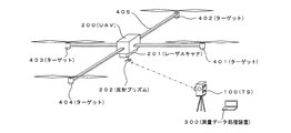
本実施形態の概要を図1に示す。図1には、飛行するUAV200、UAV200の追跡しつつその測位を行うTS(トータルステーション)100が示されている。図1には、UAV200にレーザースキャナ201を搭載し、UAV200を飛行させながら地上や建築物等の対象物のレーザースキャンを行い、当該対象物の三次元レーザースキャン点群(点群データ)を得る状態が示されている。
(Overview)
An outline of the present embodiment is shown in FIG. FIG. 1 shows a
UAV200は、市販の機体であり、飛行計画に従って自立飛行する制御部、レーザースキャナ201、通信装置、GNSSを用いた位置特定装置(GPS受信機)、IMU(慣性計測装置)、方位センサ、飛行ログやレーザースキャンデータを記憶する記憶部を備える。UAV200のIMUは、飛行制御に利用できる程度の精度であり、レーザースキャナ201の外部標定要素の算出に用いる程の精度はない。UAV200は、中央下部に専用の反射プリズム202を備えている。反射プリズム202は、入射した光を180°向きを反転させて反射する光学機能を有する。
The UAV 200 is a commercially available airframe, a control unit that autonomously flies in accordance with a flight plan, a laser scanner 201, a communication device, a position identification device (GPS receiver) using GNSS, an IMU (inertial measurement device), an orientation sensor, a flight log. And a storage unit for storing laser scan data. The IMU of the
UAV200搭載のレーザースキャナ201は、GNSSの航法衛星からの航法信号に含まれる時刻情報を用いた時計を備え、レーザースキャンデータの取得と同時に、各点が得られた取得時刻を取得する。レーザースキャンデータ(各点の位置データ)と、その取得時刻はUAV200に搭載した記憶部に記憶される。レーザースキャナ201の基本機能および基本構造は、後述するTS100が備えるレーザースキャナ112と同じである。なお通常は、軽量化や低消費電力化の関係で、レーザースキャナ201の方がレーザースキャナ112よりも構成や機能が簡略化されている。
The laser scanner 201 mounted on the UAV 200 includes a clock using time information included in the navigation signal from the GNSS navigation satellite, and acquires the acquisition time when each point was acquired simultaneously with the acquisition of the laser scan data. Laser scan data (position data of each point) and its acquisition time are stored in a storage unit mounted on the
また、TS100は、飛行するUAV200を追跡し、その測位を行う。TS100もGNSSの航法信号を利用してUAV200の測位データとその時点の時刻を取得する。このデータは、TS100内部の記憶部(あるいはTS100に接続されたデータ記憶装置)に記憶される。また、TS100は、レーザースキャナ112(図3参照)を備え、レーザースキャナ112のレーザースキャン機能により、UAV200の姿勢を計測(特定)する。TS100の詳細については後述する。
In addition, the TS 100 tracks the flying UAV 200 and performs positioning thereof. The
図1には、PCを利用して実現した測量データ処理装置300が示されている。測量データ処理装置300は、レーザースキャナ201が得たレーザースキャンデータの座標を、TS100を原点とした地上座標系における座標に座標変換し、更にこの座標変換を行ったレーザースキャンデータに基づく三次元モデルの作成を行う。この際、UAV200の姿勢が算出される。測量データ処理装置300は、UAV200の姿勢を算出する装置として利用することもできる。測量データ処理装置300の詳細については後述する。
FIG. 1 shows a survey
ここでは、UAVからレーザースキャンを行う場合を例に挙げ説明するが、UAVにカメラを搭載し、航空写真測量を行う場合におけるUAVの姿勢の特定(姿勢の計測)に本実施形態の技術を利用することができる。また、本実施形態は、航空機の飛行目的に限定されず、飛行する航空機の姿勢を計測する技術に広く利用することができる。 Here, a case where laser scanning is performed from a UAV will be described as an example. However, the technology of the present embodiment is used for specifying a UAV posture (measurement of posture) when a camera is mounted on the UAV and aerial photogrammetry is performed. can do. Further, the present embodiment is not limited to the purpose of flying an aircraft, and can be widely used for techniques for measuring the attitude of a flying aircraft.
(原理の説明)
以下、レーザースキャナ201が得たレーザースキャンデータの座標を、TS100を原点とした地上座標系における座標に座標変換する原理について説明する。この処理では、UAV200の位置の特定、UAV200の姿勢の特定、UAV200に固定された座標系の地上座標系への座標変換が行われる。以下、各処理について説明する。
(Description of principle)
Hereinafter, the principle of coordinate conversion of the coordinates of the laser scan data obtained by the laser scanner 201 to the coordinates in the ground coordinate system with TS100 as the origin will be described. In this process, the position of the
(UAVの位置の特定)
飛行するUAV200の位置(空中での三次元位置)は、TS100によりリアルタイムに特定され、その位置座標は、図2のXYZ座標系(地上座標系)上で記述される。TS100によるUAV200の追跡と測位は、UAV200に搭載された反射プリズム202をTS100のターゲット追跡機能を用いて追跡し、またTS100の測位機能により測位(三次元位置の特定)することで行われる。TS100のターゲット(反射プリズム)の追跡機能と測位機能については後述する。
(Identification of UAV location)
The position (three-dimensional position in the air) of the flying
UAV200における反射プリズム202およびレーザースキャナ201の位置関係は予め調べられ既知である。また、UAV200に対するレーザースキャナ201の姿勢(向き)の情報も予め既知な情報として取得されている。反射プリズム202の位置が特定されることで、UAV200の位置が特定される、この例では、UAV200の位置としては、レーザースキャナ201の位置(光学的なレーザースキャンの原点位置)が採用される。UAV200の位置として、UAV200の構造中心の位置、UAV200の重心の位置、IMUの位置等が採用可能である。
The positional relationship between the reflecting prism 202 and the laser scanner 201 in the
TS100は、地上座標系である図2に示すXYZ座標系上で予め位置が特定されている。この例では、TS100の位置がXYZ座標系の原点に設定されている。よって、TS100によりUAV200の位置を測位することで、地上座標系であるXYZ座標系上におけるUAV200の位置が特定される。なお、UAV200の位置の特定(測位)を後述する半球形状の反射ターゲット401〜404の位置から行う形態も可能である。
The position of TS100 is specified in advance on the XYZ coordinate system shown in FIG. In this example, the position of TS100 is set to the origin of the XYZ coordinate system. Therefore, by measuring the position of the
(UAVの姿勢の特定)
UAV200は、識別可能な3つ以上の反射ターゲットを備え、この3つ以上の反射ターゲットの位置をTS100が装備するレーザースキャナ112の機能によって特定することで、UAV200の姿勢が算出される。
(Identification of UAV posture)
The
図1に示すようにUAV200は、四方に延在する4本のアーム(腕)405を備え、この4本のアーム405の先端のそれぞれには、反射ターゲットとして機能する半球形状のターゲット401,402,403,404が配置されている。ターゲット401〜404は、それぞれ異なる曲率を有する半球状の金属反射面を有している。ターゲット401〜404は、鉛直下方が凸となる向きで配置されている。ターゲット401〜404それぞれの曲率とUAV200における曲率中心の位置は、既知のデータとして予め取得されている。
As shown in FIG. 1, the
レーザースキャナ112によって、ターゲット401〜404を含む領域がレーザースキャンされ、ターゲット401〜404からのレーザースキャン反射光から、ターゲット401〜404それぞれの曲率半径が算出される。そして、曲率半径の違いからターゲット401〜404の識別および特定が行われる。また、曲率中心の位置を特定することで、4つのターゲット401〜404のXYZ座標系(地上座標系)における位置の特定が行われる。レーザースキャンを用いて半球状(または球状)のターゲットの曲率半径や曲率中心を求める技術については、特願2017−011130号公報に記載されている。 The region including the targets 401 to 404 is laser-scanned by the laser scanner 112, and the curvature radii of the targets 401 to 404 are calculated from the laser scan reflected light from the targets 401 to 404. And identification and specification of the targets 401-404 are performed from the difference in curvature radius. Further, by specifying the position of the center of curvature, the positions of the four targets 401 to 404 in the XYZ coordinate system (ground coordinate system) are specified. A technique for obtaining the radius of curvature and the center of curvature of a hemispherical (or spherical) target using laser scanning is described in Japanese Patent Application No. 2017-011130.
例えば、半球状のターゲット401がレーザースキャナ112によってレーザースキャンされる場合を考える。この場合、ターゲット401におけるレーザースキャン光の反射点は、球面上の経路に沿ったものとなる。この反射点をつないだ線はターゲット401表面の曲面に沿った曲線であり、この曲線を複数得ることで、レーザースキャン点群で構成される曲面が得られる。この曲面の曲率半径がターゲット401の曲率半径となる。またその曲率中心が半球状を有するターゲット401の曲率中心となる。この原理により、TS100から見たターゲット401〜404の曲率半径と曲率中心の位置が取得される。
For example, consider a case where the hemispherical target 401 is laser-scanned by the laser scanner 112. In this case, the reflection point of the laser scanning light at the target 401 is along a path on the spherical surface. The line connecting the reflection points is a curve along the curved surface of the surface of the target 401. By obtaining a plurality of these curves, a curved surface constituted by a laser scan point group can be obtained. The curvature radius of this curved surface becomes the curvature radius of the target 401. The center of curvature is the center of curvature of the target 401 having a hemispherical shape. Based on this principle, the curvature radius and the position of the curvature center of the targets 401 to 404 viewed from the
ターゲット401〜404は、曲率半径が異なるように設定されているので、計測された曲率半径の違いから、ターゲット401〜404を個別に識別できる。こうして、ターゲット401〜404それぞれの三次元位置の特定が行われる。 Since the targets 401 to 404 are set to have different curvature radii, the targets 401 to 404 can be individually identified from the difference in the measured curvature radii. In this way, the three-dimensional position of each of the targets 401 to 404 is specified.
例えば、レーザースキャナ112によるレーザースキャンによって特定したターゲット401の三次元位置(x1,y1,z1)、ターゲット402の三次元位置(x2,y2,z2)、ターゲット403の三次元位置(x3,y3,z3)、ターゲット404の三次元位置(x4,y4,z4)が判明したとする。 For example, the three-dimensional position (x 1 , y 1 , z 1 ) of the target 401 identified by laser scanning by the laser scanner 112, the three-dimensional position (x 2 , y 2 , z 2 ) of the target 402, and the three-dimensional position of the target 403 Assume that the position (x 3 , y 3 , z 3 ) and the three-dimensional position (x 4 , y 4 , z 4 ) of the target 404 are found.
ここで例えば、ターゲット401と404がUAV200の前方に配置され、ターゲット402と403がUAV200の後方に配置されているとする。この場合、ターゲット4001〜404の曲率中心を含む面を特定し、またターゲット402からターゲット401に向かうベクトルを算出することで、UAV200の姿勢(向き)が判る。
Here, for example, it is assumed that the targets 401 and 404 are arranged in front of the
ターゲット401〜404の中の3以上の位置を測位することで、UAV200の位置の特定を行うこともできる。この場合、ターゲット401〜404とUAV200の位置とみなす部位(例えば、レーザースキャナ201)との位置関係が予め既知とされ、ターゲット401〜404の中の少なくとも3か所の位置が特定されることで、UAV200の位置が特定される。
The position of the
(座標系の説明)
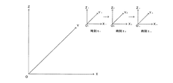
図2には、地上座標系であるXYZ座標系が示されている。XYZ座標系は、地上に固定されたTS100の位置を原点Oとする三次元直交直線座標系である。XYZ座標系における各座標軸の方向の設定は任意であるが、例えばZ軸を鉛直上方の方向、Y軸を北の方向、X軸を東の方向に設定する態様が挙げられる。
(Explanation of coordinate system)
FIG. 2 shows an XYZ coordinate system that is a ground coordinate system. The XYZ coordinate system is a three-dimensional orthogonal linear coordinate system with the origin O as the position of the TS100 fixed on the ground. Setting of the direction of each coordinate axis in the XYZ coordinate system is arbitrary. For example, a mode in which the Z axis is set in a vertically upward direction, the Y axis is set in a north direction, and the X axis is set in an east direction.
X1Y1Z1座標系、X2Y2Z2座標系、・・・・XnYnZn座標系(n=1,2,3・・・)は、飛行するUAV200に固定された三次元直交直線座標系である。XnYnZn座標系は、移動するUAV200に固定された局所座標系でありUAV200の移動に従って、原点の位置と座標軸の向きは変化する。図2には、時刻t1におけるX1Y1Z1座標系、時刻t2におけるX2Y2Z2座標系、時刻tnにおけるXnYnZn座標系(n=1,2,3・・・)が示されている。
X 1 Y 1 Z 1 coordinate system, X 2 Y 2 Z 2 coordinate system,... X n Y n Z n coordinate system (n = 1, 2, 3...) Is fixed to the flying
図2の場合、UAV200に搭載されたレーザースキャナ201によるレーザースキャンによって、時刻t1においてX1Y1Z1座標系で点O1を原点としたレーザースキャン点群が得られ、時刻t2においてX2Y2Z2座標系で点O2を原点としたレーザースキャン点群が得られ、時刻tnにおいてXnYnZn座標系で点Onを原点としたレーザースキャン点群が得られる。
In the case of FIG. 2, the laser scan by the laser scanner 201 mounted on the
ここで、レーザースキャン光が複数条同時に照射され、またその反射光が検出された場合、時刻tnで得られるXnYnZn座標系におけるスキャン点が複数同時に得られる。また、ある時間幅(t1〜t2)で得られたスキャン点を同一時刻(例えばt1とt2の中間の時刻)に得られたスキャン点と見なして処理する形態も可能である。
Here, when a plurality of laser scanning lights are simultaneously irradiated and the reflected light is detected, a plurality of scanning points in the X n Y n Z n coordinate system obtained at time t n are obtained simultaneously. Further, it is also possible form of processing is regarded as a certain time width (
(スキャンデータの統合:座標変換)
以下、UAV200に固定されたX1Y1Z1座標系、X2Y2Z2座標系、・・・・XnYnZn座標系(n=1,2,3・・・)を地上座標系であるXYZ座標系に統合し、飛行するUAV200から得たレーザースキャンデータを地上座標系XYZ上で記述する処理について説明する。
(Scan data integration: coordinate conversion)
Hereinafter, the X 1 Y 1 Z 1 coordinate system, X 2 Y 2 Z 2 coordinate system fixed to the
この処理は、時刻tnにおいて、XnYnZn座標系上の点をXYZ座標系に座標変換する処理である。つまり、時刻tnにおいて、XnYnZn座標系を回転させて、XnYnZn座標系の向きをXYZ座標系に合わせ、更にXnYnZn座標系を平行移動させてXnYnZn座標系とXYZ座標系の原点を合わせる処理である。この処理は、時刻tnにおける上記の回転のための回転行列をRn、平行移動のためのベクトルをTnとして、数学的に下記の数1で示される。 This process is, at time t n, a process of coordinate conversion points on X n Y n Z n coordinate system to the XYZ coordinate system. That is, at time t n, by rotating the X n Y n Z n coordinate system, the combined X n Y n Z n coordinate system orientation in the XYZ coordinate system, and further translating the X n Y n Z n coordinate system In this process, the origins of the X n Y n Z n coordinate system and the XYZ coordinate system are aligned. This process is mathematically expressed by the following equation 1 , where R n is a rotation matrix for the rotation at time t n and T n is a vector for translation.
XnYnZn座標系(n=1,2,3・・・)の全てにおいて、上記数1の処理を行うことで、飛行するUAV200から得たレーザースキャンデータを地上座標系上で記述することができる。
In all of the X n Y n Z n coordinate systems (n = 1, 2, 3...), The laser scan data obtained from the flying
数1における回転行列Rnは、XnYnZn座標系をどのように回転させればXYZ座標系と向きが一致するのかを決める行列であり、時刻tnにおけるXYZ座標系に対するXnYnZn座標系の向きにより決まる。XnYnZn座標系は、UAV200に固定された座標系であるから、時刻tnにおけるXYZ座標系に対するXnYnZn座標系の向きは、時刻tnにおけるXYZ座標系(地上座標系)におけるUAV200の姿勢(向き)から求まる。
The rotation matrix R n in
ところで、XYZ座標系におけるUAV200の姿勢は、ターゲット401〜404を用いて特定できる。よって、時刻tnにおけるターゲット401〜404の位置を特定し、時刻tnにおけるUAV200のXYZ座標系における姿勢を求めることで、時刻tnにおける回転行列Rnが得られる。
By the way, the posture of the
ベクトルTnは、時刻tnにおけるXnYnZn座標系の原点Onを始点とし、XYZ座標系の原点Oを終点とするベクトルとして求められる。ここで、XYZ座標系の原点Oは、TS100の設置位置であり、XnYnZn座標系の原点Onは、TS100により測位されるUAV200の位置(レーザースキャナ201のスキャン光の光源位置)である。よってベクトルTnは、XYZ座標系の原点OとUAV200の位置Onとを結ぶベクトルとして求められる。 Vector T n is a X n Y n Z n origin O n of the coordinate system a starting point at time t n, it is determined as a vector and ending at the origin O of the XYZ coordinate system. Here, the origin O of the XYZ coordinate system is the installation position of the TS100, X n Y n Z n coordinate system origin O n of the light source position of the scanning beam position UAV200 being positioning (laser scanner 201 by TS100 ). Thus the vector T n is obtained as a vector connecting the position O n of the origin O and UAV200 of the XYZ coordinate system.
回転力列RnとベクトルTnは、XnYnZn座標系と結びついた時刻tn毎に求められる。各時刻において求めた回転行列RnとベクトルTnを用いてXnYnZn座標系上で記述されたレーザースキャン点をXYZ座標系に座標変換することで、各レーザースキャン点がXYZ座標系上で記述される。 The torque train R n and the vector T n are obtained every time t n associated with the X n Y n Z n coordinate system. X n Y n Z n a laser scanning point described on a coordinate system by coordinate conversion into XYZ coordinate system, the laser scanning point XYZ coordinates using the rotation matrix R n and the vector T n determined at each time Described on the system.
(TS(トータルステーションの構成))
図3に図1に示すTS100のブロック図が示されている。TS100は、GNSSを用いた位置測定装置、画像を取得するカメラ、ターゲット(UAV200の反射プリズム202)を探索し、追尾する追尾レーザースキャン機能、測距用レーザー光を用いてターゲット(反射プリズム202)までの距離を測距するレーザー測距機能、レーザー測距されたターゲットの方向(水平角と垂直角(仰角または俯角))を計測する機能、ターゲットまでの距離と方向からターゲットの三次元位置を算出する機能、外部の機器との間で通信を行う機能、点群データを得るためのレーザースキャン機能を有する。
(TS (total station configuration))
FIG. 3 shows a block diagram of the
ターゲットまでの距離と方向を計測することで、TS100に対するターゲットの位置を測定できる。ここで、TS100の位置が判っていれば、ターゲット(この場合はUAV200の反射プリズム202)の地図座標系における位置(緯度・経度・平均海面からの標高もしくは直交座標系上のXYZ座標)を知ることができる。この機能は、市販のTSが持っている機能であり、特別なものではない。TSに関する技術としては、例えば、特開2009−229192号公報や特開2012−202821号公報等に記載されている。なお、地図座標系というのは、地図情報を扱う座標系(例えば、緯度,経度,標高)であり、例えばGNSSで得られる位置情報は通常地図座標系で記述される。
By measuring the distance and direction to the target, the position of the target with respect to TS100 can be measured. If the position of the
TS100は、カメラ101、ターゲット探索部102、測距部103、水平・垂直方向検出部104、水平・垂直方向駆動部105、データ記憶部106、位置測定部107、通信装置108、ターゲット位置算出部109、UAV追跡制御部111、レーザースキャナ112、レーザースキャン範囲設定部113、制御用マイコン114を備えている。
The
図3に示すその他の機能部は、専用のハードウェアで構成してもよいし、マイコンによりソフトウェア的に構成してもよい。図3の構成を実現するために利用するハードウェアとしては、各種の電子デバイス(例えば、カメラを構成するカメラモジュールや通信装置108を構成する無線モジュール)、モータ等を利用した各種の駆動機構、センサ機構、光学部品、各種の電子回路、CPU(Central Processing Unit)、ASIC(Application Specific Integrated Circuit)、FPGA(Field Programmable Gate Array)等が挙げられる。以上のハードウェアの構成に関しては、UAV200についても同じである。
The other functional units shown in FIG. 3 may be configured by dedicated hardware, or may be configured by software using a microcomputer. As hardware used to realize the configuration of FIG. 3, various electronic devices (for example, a camera module configuring the camera and a wireless module configuring the communication device 108), various driving mechanisms using a motor, and the like, Examples include sensor mechanisms, optical components, various electronic circuits, CPU (Central Processing Unit), ASIC (Application Specific Integrated Circuit), FPGA (Field Programmable Gate Array), and the like. The above hardware configuration is the same for the
カメラ101は、UAV200やターゲット等の測量対象の動画像または静止画像を撮影する。カメラ101は、CCDやCMOSセンサを用いたカメラモジュールを利用して構成され、望遠鏡を介して測位対象(例えばUAV200)の撮影を行い、その画像データを得る。通常、カメラ101が望遠鏡を介して撮影した画像を利用して測量対象のターゲットの概略の視準がオペレータにより行われ、その後自動追尾機能による自律動作によりターゲットの精密な視準が行われる。カメラ101が撮影した画像のデータは、測距対象に係る測定時刻、測定方向、測定距離、測定対象の位置等のデータと関連付けされて適当な記憶領域に記憶することができる。
The
ターゲット探索部102は、三角錐型または扇形ビームを有した追尾用レーザー光を用いたタ−ゲット(反射プリズム202)の探索および追尾を行う。ターゲットの探索および追尾は、TS100を基準位置として行われる。TSによるターゲットの探索および追尾に係る技術は、例えば日本国特許第5124319号公報に記載されている。
The
測距部103は、測距用レーザー光を用いたターゲットまでの距離の計測を行う。測距部103は、測距用レーザー光の発光素子、照射光学系、受光光学系、受光素子、測距演算部、測距基準光の光路を備えている。対象物までの距離は、対象物から反射された測距光と基準光の位相差から算出される。距離の算出方法は、通常のレーザー測距と同じである。 The distance measuring unit 103 measures the distance to the target using the distance measuring laser beam. The distance measuring unit 103 includes a light emitting element for distance measuring laser light, an irradiation optical system, a light receiving optical system, a light receiving element, a distance calculating unit, and an optical path for distance measuring reference light. The distance to the object is calculated from the phase difference between the distance measuring light reflected from the object and the reference light. The method for calculating the distance is the same as that for normal laser ranging.
水平・垂直方向検出部104は、測距部103が測距したターゲット(反射プリズム202)のTS100から見た水平方向角と垂直方向角(仰角および俯角)を計測する。ターゲット探索部102および測距部103の光学系を備えた筐体部分は、水平回転および仰角(俯角)制御が可能であり、水平方向角と垂直方向角は、エンコーダにより計測される。このエンコーダの出力が水平・垂直方向角検出部104で検出され、水平方向角と垂直方向角(仰角および俯角)の計測が行われる。水平・垂直方向検出部104の出力から、TS100から見た反射プリズム202の方向が判る。
The horizontal / vertical
水平・垂直方向駆動部105は、ターゲット探索部102および測距部103の光学系を備えた筐体部分の水平回転および仰角制御(および俯角制御)を行うモータ、該モータの駆動回路、該駆動回路の制御回路を含む。なお、この筐体部分には後述するレーザースキャナ112も配置されている。データ記憶部106は、TS100の動作に必要な制御プログラム、各種のデータ、測量結果等を記憶する。
The horizontal / vertical
位置測定部107は、GNSSを用いたTS100の位置の測定を行う。位置測定部107は、相対測位と単独測位の両方を行う機能を有する。相対測位を行える環境であれば、相対測位を用いたTS100の位置の測定が好ましいが、相対測位が困難な場合は単独測位によるTS100の位置の測定が行われる。
The
通信装置108は、外部の機器との間で通信を行う。TS100は、外部の端末(専用端末、PC、タブレット、スマートフォン等)による操作が可能であり、この際の通信が通信装置108を用いて行われる。また、通信装置108は、TS100の動作に必要な各種のデータの受け付け、およびTS100が取得した各種のデータの外部への出力を行う。例えば、TS100からインターネット回線を介して地図情報や地形情報を扱うデータサーバにアクセスし、測量に係る各種の情報をTS100が取得することができる。
The
ターゲット位置算出部109は、ターゲット(この場合は、UAV200搭載の反射プリズム202)までの距離と方向からTS100に対するターゲットの位置(座標)を算出する。ここで、ターゲットまでの距離は、測距部103で得られ、ターゲットの方向は水平・垂直方向検出部104で得られる。基準位置となるTS100の位置は、位置測定部107で特定されるので、TS100に対するターゲットの位置を求めることで、ターゲットの地図座標系(図2のXYZ座標系)における位置を求めることができる。
The target
UAV追跡制御部111は、補足したUAVを追尾する制御を行う。すなわち、ターゲット探索部102で検出した追尾光(UAVから反射した追尾光)の入射方向の変化に対応させてTSの方向を制御し、空中を移動するUAVに常にTS100の光軸が向くようにする動的な制御がUAV追跡制御部111で行われる。具体的には、ターゲット(反射プリズム202)から反射した追尾光のTS100に対する入射方向の変化を検出し、それに基づき反射プリズム202の位置にTS100の光軸(測距部103からの測距光の光軸)が常に向くように、水平・垂直方向駆動部105に制御信号を出力する処理がUAV追跡制御部111で行われる。
The UAV tracking control unit 111 performs control for tracking the supplemented UAV. That is, the direction of the TS is controlled in accordance with the change in the incident direction of the tracking light (tracking light reflected from the UAV) detected by the
レーザースキャナ112は、測距用レーザー光をスキャン光として用いて点群データ(レーザースキャン点群)を得る。点群データは、対象物を三次元座標が判明した点の集合として捉えたデータである。この例では、ターゲット探索部102とレーザースキャナ112は別構成であり、レーザースキャナ112は、ターゲット探索部102とは別に動作する。
The laser scanner 112 obtains point cloud data (laser scan point cloud) using the distance measuring laser light as scan light. The point cloud data is data that captures an object as a set of points whose three-dimensional coordinates are known. In this example, the
レーザースキャナ112は、ターゲット探索部102および測距部103の光学系を備えた筐体部分に配置されており、ターゲット探索部102および測距部103の光学系の光軸を中心した範囲のレーザースキャンが可能である。
The laser scanner 112 is arranged in a housing portion having the optical system of the
レーザースキャナ112が扱うレーザー光の波長は、ターゲット探索部102が用いるレーザー光と干渉しないように、ターゲット探索部102が用いるレーザー光とは別の波長が選択されている。レーザースキャナ112については、例えば特開2010−151682号公報、特開2008―268004号公報、米国特許8767190号公報、米国特許7969558号公報等に記載されている。また、レーザースキャナ112として、スキャンを電子式に行う形態のもの(例えば、US2015/0293224号公報参照)を採用することもできる。
The wavelength of the laser light handled by the laser scanner 112 is selected to be different from the laser light used by the
以下、レーザースキャナ112について説明する。レーザースキャナ112は、測距用レーザー光の照射部、対象物から反射した測距用レーザー光を受光する受光部、測距用レーザー光の飛行時間に基づき対象物までの距離を検出する測距部、測距用レーザー光の照射方向(測距方向)を検出する測距方向検出部、自身の位置と測距距離と測距方向とに基づき測距用レーザー光の反射点の三次元位置を算出する測距対象点の位置算出部、測距用レーザー光の照射方向とその反射光の受光方向(測距光の光軸)の方向を制御するスキャン制御部を備える。 Hereinafter, the laser scanner 112 will be described. The laser scanner 112 is a distance measuring laser beam irradiation unit, a light receiving unit that receives the distance measuring laser beam reflected from the object, and a distance measuring unit that detects the distance to the object based on the flight time of the distance measuring laser beam. A distance measuring direction detection unit for detecting the irradiation direction (ranging direction) of the distance measuring laser beam, and the three-dimensional position of the reflection point of the distance measuring laser light based on its own position, distance measuring distance and distance measuring direction A position calculation unit for calculating a distance measurement target point, and a scan control unit for controlling the irradiation direction of the distance measurement laser light and the direction of the reflected light (the optical axis of the distance measurement light).
測距用レーザー光は、特定の繰り返し周波数でパルス出力され、スキャンされながら特定の範囲に照射される。測距用レーザー光の飛行時間から反射点までの距離が計算される。通常は、装置内に設けられた基準光路を飛翔したリファレンス光と対象物に照射されそこから反射された測距光との位相差から対象物までの距離が算出される。測距された距離、測距用レーザー光の照射方向およびレーザースキャナ112の位置から、反射点の三次元位置が計算される。この反射点の位置を多数測定することで点群データが得られる。 The distance measuring laser light is output as a pulse at a specific repetition frequency, and irradiated to a specific range while being scanned. The distance from the flight time of the laser beam for distance measurement to the reflection point is calculated. Usually, the distance to the object is calculated from the phase difference between the reference light flying in the reference optical path provided in the apparatus and the distance measuring light irradiated to the object and reflected from the object. The three-dimensional position of the reflection point is calculated from the distance measured, the irradiation direction of the distance measuring laser light, and the position of the laser scanner 112. Point cloud data can be obtained by measuring a number of positions of the reflection points.
ここで、TS100は、地図座標系における座標が既知の位置または位置測定部107により精密に測位された位置に設置されている。TS100におけるレーザースキャナ112の位置と向きは、予め既知の情報として取得されており、レーザースキャナ112の地図座標系における位置(スキャンの原点の位置)は、予め取得されている。この例では、図2のXYZ座標系の原点にTS100が配置され、レーザースキャナ112が取得するレーザースキャンデータは、XYZ座標系における点の座標データとして取得される。
Here, the
測距用レーザー光が特定の発振周波数でスキャンして照射されることで対象物における多数の反射点それぞれの三次元座標(レーザースキャナ112を原点とする座標系における三次元座標)が取得される。この対象物における多数の反射点の集合が点群データとなる。点群データでは、三次元位置が特定された点の集合として対象物が捉えられる。 The three-dimensional coordinates (three-dimensional coordinates in the coordinate system with the laser scanner 112 as the origin) of each of a number of reflection points on the object are acquired by scanning and irradiating the distance measuring laser light with a specific oscillation frequency. . A set of a large number of reflection points on this object becomes point cloud data. In the point cloud data, an object is captured as a set of points whose three-dimensional positions are specified.
レーザースキャナ112は、カメラ101が取得した画像から取得した色を用いて、点群データ各点に配色することができる。もしくは点の反射強度(インテンシティー)を検出することで、点群データ各点の反射強度に関するデータも得られる。
The laser scanner 112 can color each point cloud data using the color acquired from the image acquired by the
レーザースキャナ112は、UAV追跡制御部111が追跡するUAV200を中心とする空域を重点的にレーザースキャンし、ターゲット401〜404からのスキャン反射光のデータを取得する。すなわち、TS100は、UAV200の反射プリズム202を追跡した状態で、測距部103は飛行するUAV200を指向し、UAV200(反射プリズム202)の測距を行っている。つまり、TS100から見たUAV200の方向はTS100の側で分かっている。このTS100から見たUAV200の方向を重点としたレーザースキャンをレーザースキャナ112が行うことで、ターゲット401〜404からのスキャン反射光のデータが効率よく得られる。
The laser scanner 112 mainly performs laser scanning on the airspace centered on the
レーザースキャナ112は、TS100を原点とするスキャン点の三次元座標の値と、当該スキャン点の取得時刻のデータを取得する。すなわち、TS100を原点とする三次元座標を特定した点群データと、この点群データを構成する各点の取得時刻とを関連付けしたデータを取得する。時刻のカウントは、位置測定部107がGNSS航法衛星から受信する時刻データに基づいて行われる。
The laser scanner 112 acquires the three-dimensional coordinate value of the scan point with the
レーザースキャン範囲設定部113は、上述したレーザースキャナ112のスキャン範囲の設定を行う。TS100から見たUAV200(反射プリズム202)の方向は、水平・垂直方向検出部104の出力から判る。レーザースキャン範囲設定部113は、水平・垂直方向検出部104の出力から得られるUAV200の方向を中心とした範囲(空域)をスキャン範囲に設定する。このレーザースキャン範囲の設定を行うことで、ターゲット401〜404のレーザースキャンを効果的に行うことができる。
The laser scan range setting unit 113 sets the scan range of the laser scanner 112 described above. The direction of the UAV 200 (reflecting prism 202) viewed from the
ターゲット401〜404のレーザースキャンは、ターゲット401〜404の曲率半径を取得できる程度の密度で行う必要があり、極力高い密度で行うことが望ましい。よって、TS100から見たUAV200の方向を重点的にレーザースキャンするレーザースキャン範囲の設定を行うことで、ターゲット401〜404へのスキャン密度が高められ、ターゲット401〜404の識別およびその位置の特定の精度を高めることができる。
Laser scanning of the targets 401 to 404 needs to be performed with a density that can acquire the radius of curvature of the targets 401 to 404, and is desirably performed with a density as high as possible. Therefore, by setting a laser scan range in which laser scanning is performed focusing on the direction of the
スキャン範囲の設定は、ターゲット401〜404の内の最低3つ以上のターゲットがスキャン範囲に含まれるように設定する。なお、反射プリズム202も利用してUAV200の姿勢を求める場合は、ターゲット401〜404の内の最低2つ以上のターゲットがスキャン範囲に含まれるように設定する。通常は、UAV200に指向した方向を中心に、UAV200の全体が含まれる範囲を設定し、その範囲でレーザースキャンが行われるようにする。制御用マイコン114は、後述する処理の手順の制御およびTS100全体の動作の制御を行う。
The scan range is set so that at least three of the targets 401 to 404 are included in the scan range. Note that when the posture of the
(測量データ処理装置)
図4は、測量データ処理装置300のブロック図である。測量データ処理装置300は、図2に関連して説明した原理に基づき、UAV200が得たレーザースキャンデータを地上座標系に座標変換する処理を行う。測量データ処理装置300における処理を行うことで、飛行するUAV200から得たレーザースキャンデータに基づく三次元モデルを作成することができる。また、上記の座標変換の前段階の処理として、各時刻におけるUAV200の姿勢を算出する処理を測量データ処理装置300は行う。
(Surveying data processor)
FIG. 4 is a block diagram of the survey
測量データ処理装置300は、レーザースキャンデータ1取得部301、レーザースキャンデータ2取得部302、曲率半径算出部303、曲率中心位置算出部304、UAV姿勢算出部305、座標変換式算出部306、座標変換部307、三次元モデル作成部308、通信装置309を有する。
The survey
測量データ処理装置300は、コンピュータとしての機能を有し、CPU、メモリ、その他演算回路、インターフェース回路およびインターフェース機能を有している。測量データ処理装置300を実現するための電子回路としては、CPU(Central Processing Unit)、ASIC(Application Specific Integrated Circuit)、FPGA(Field Programmable Gate Array)に代表されるPLD(Programmable Logic Device)が挙げられる。
The survey
測量データ処理装置300をPC(パーソナルコンピュータ)やWS(ワークステーション)を用いて実現することもできる。この場合、図4の各機能部の機能を実現するための動作プログラムをPCやWSにインストールし、該動作プログラムの実行により、図4に示す各機能部をソフトウェア的に構成する。なお一部の機能部をFPGA等の専用のハードウェアで構成する形態も可能である。
The survey
各機能部を専用のハードウェアで構成するのか、CPUにおけるプログラムの実行によりソフトウェア的に構成するのかは、要求される演算速度、コスト、消費電力等を勘案して決定される。機能部を専用のハードウェアで構成することとソフトウェア的に構成することは、上述した違いはあるが、特定の機能を実現するという観点からは、等価である。 Whether each functional unit is configured by dedicated hardware or by software by executing a program in the CPU is determined in consideration of required calculation speed, cost, power consumption, and the like. Although the functional units are configured by dedicated hardware and configured by software, there are differences as described above, but they are equivalent from the viewpoint of realizing a specific function.
図4に示す機能部の一または複数をデータ通信回線で繋がれた個別のハードウェアで実現する形態も可能である。例えば、図4の一部の機能をインターネット回線で接続されたデータ処理サーバで実現する形態も可能である。 A form in which one or more of the functional units shown in FIG. 4 are realized by individual hardware connected by a data communication line is also possible. For example, a form in which a part of the functions in FIG. 4 is realized by a data processing server connected by an Internet line is also possible.
PCやWSを用いて測量データ処理装置300を実現する場合、PCやWSのインターフェース(例えばGUI(グラフィカル・ユーザ・インターフェース))を利用して測量データ処理装置300の操作が行われる。測量データ処理装置300の操作を専用端末、スマートフォン、タブレット等を用いて行う形態も可能である。
When the surveying
レーザースキャンデータ1取得部301は、TS100のレーザースキャナ112が得たレーザースキャンデータを取得する。このレーザースキャンデータは、TS100を原点とした図2のXYZ座標系における各スキャン点の三次元座標とその取得時刻のデータである。
The
レーザースキャンデータ2取得部302は、UAV200が装備するレーザースキャナ201が取得したレーザースキャンデータを取得する。このレーザースキャンデータは、UAV200(レーザースキャナ201)を原点とした三次元座標系(図2のXnYnZn座標系:UAV座標系)上における三次元位置である。この座標系は、UAV200に固定された座標系であり、その向きとUAV200の構造との関係は予め取得されている。例えば、UAV200の前方をX軸方向、左側面方向をY軸方向、鉛直上方をZ軸方向というようにUAV200の構造と上記三次元座標系(XnYnZn座標系:UAV座標系)との関係は予め特定されている。
The
XnYnZn座標系は、UAV200に固定されているので、UAV200の移動に従って、XYZ座標系(地上座標系)上における位置と向きが変化する。勿論、UAV200が静止していれば、XnYnZn座標系のXYZ座標系に対する位置の変化はなく、またUAV200が移動しても向きの変化がなければ、XnYnZn座標系のXYZ座標系に対する向きの変化はない。
Since the X n Y n Z n coordinate system is fixed to the
曲率半径算出部303は、レーザースキャナ112によるターゲット401〜404に対するレーザースキャンの結果に基づき、ターゲット401〜404それぞれの曲率半径を算出する。ターゲット401〜404それぞれの曲率半径は既知であり、規定の曲率半径に合致する曲率半径が算出されることで、ターゲット401〜404の識別および特定が行われる。
The curvature
この処理では、レーザースキャン点群にフィッティングする球面を求め、その曲率を求める演算が行われる。この例では、予めターゲット401〜404の曲率は既知であり、この曲率に対応する曲面にフィッティングするレーザースキャン点が抽出される。 In this process, a sphere to be fitted to the laser scan point group is obtained, and an operation for obtaining its curvature is performed. In this example, the curvatures of the targets 401 to 404 are known in advance, and a laser scan point that fits a curved surface corresponding to this curvature is extracted.
曲率中心位置算出部304は、曲率半径算出部303で曲率半径が算出され、更に予め定めた曲率半径(ターゲット401〜404に設定された曲率半径)に合致する曲率半径を有する球面の曲率中心の位置を算出する。この処理では、上述した規定の曲面にフィッティングしたレーザースキャン点群により形成される曲面の曲率中心の座標が算出される。
The curvature center
ターゲット401〜404の識別とその位置(曲率中心の位置)の特定に利用するレーザースキャン点群(レーザースキャンのより得られた点群データ)は、時刻tnを時間軸上の中心とした極力短い期間Δtに得られたものを用いることが望ましい。これは、UAV200が飛行(移動)している過程でTS100からのレーザースキャンが行われるので、Δtが大きいと、レーザースキャナ112が得たレーザースキャン点群と対象物であるUAV200の形状との対応関係の歪みが大きくなるからである。
The laser scan point group (point group data obtained by laser scanning) used for identifying the targets 401 to 404 and specifying their position (position of the center of curvature) is as short as possible with the time tn as the center on the time axis. It is desirable to use what was obtained in the period Δt. This is because laser scanning from the
よって、利用するレーザースキャナ112のスキャン速度、スキャン密度、スキャン分解能、要求されるUAV200の姿勢の計測結果の精度に鑑み、極力上記Δtの長さを短く設定する。
Therefore, the length of Δt is set as short as possible in view of the scanning speed of the laser scanner 112 to be used, the scanning density, the scanning resolution, and the accuracy of the required measurement result of the posture of the
UAV姿勢算出部305は、レーザースキャンデータ1取得部301が取得したレーザースキャンデータ(TS100のレーザースキャナ112が取得したレーザースキャンデータ)に基づき、UAV200の姿勢を取得する。この処理は、曲率中心位置算出部304が算出した3点以上の点(ターゲット401〜404の中の3つ以上の位置)の座標に基づいて行われる。
The UAV
曲率中心位置算出部304が算出した3点以上の点の座標は、それぞれターゲット401〜404のどれに相当する位置であるか識別できる。この識別は、既知の曲率半径の設定値の違いから行われる。また、UAV200の向きとターゲット401〜404の位置関係も既知である。よって、曲率中心位置算出部304が算出した3点以上の点の座標値から、UAV200の姿勢が求まる。
The coordinates of three or more points calculated by the curvature center
座標変換式算出部306は、XnYnZn座標系で記述されたスキャン点(点群データ)をXYZ座標系で記述するための座標変換を行うために必要な数1の変換式を算出する。具体的には、図2に関連して説明したように、時刻tnにおけるXnYnZn座標系のXYZ座標系に対する傾きから時刻tnにおける回転行列Rnを求め、また時刻tnにおけるXnYnZn座標系の原点OnとXYZ座標系の原点Oとの位置の差から並進ベクトルTnを求める。なお、回転行列Rnと並進ベクトルTnは、時刻tn毎に求められる。
Coordinate conversion
時刻tnにおける回転行列Rnは以下のようにして求められる。まず、XnYnZn座標系のXYZ座標系に対する傾きは、時刻tnにおけるUAV200の姿勢から求められる。ここで、時刻tnにおけるUAV200の姿勢は、時刻tnまたは時刻tnと見なせるタイミングで取得されたレーザースキャナ112が取得したレーザースキャン点群に基づくターゲット401〜404の曲率中心の位置に基づいてUAV姿勢算出部305において算出されている。よって、UAV姿勢算出部305の算出結果に基づき、時刻tnにおけるUAV200の姿勢から求められ、時刻tnにおける回転行列Rnが得られる。
The rotation matrix R n at time t n is obtained as follows. First, the inclination relative to the XYZ coordinate system of X n Y n Z n coordinate system is determined from the position of UAV200 at time t n. Here, the posture of the
時刻tnにおける並進ベクトルTnは、TS100の位置Oを終点、時刻tnにおいてTS100が測位したUAV200の位置Onを始点とするベクトルとして求められる。 Translation vector T n at time t n is calculated as a vector starting from the position O n of UAV200 the TS100 is positioning the position O of the TS100 endpoint, at time t n.
座標変換部307は、時刻tn毎に求められた回転行列Rnと並進ベクトルTnに基づき得られた数1を用いて、XnYnZn座標系上のスキャン点をXYZ座標系に座標変換する。時刻tnに得られたものとして扱われるレーザースキャナ201から得られたレーザースキャン点群の数の制限はない。現実的には、時刻tnにある程度の幅を持たせ、その時間範囲において得られたレーザースキャン点群が、時刻tnにおいて取得されたものとして扱われる。
The coordinate
三次元モデル作成部308は、レーザースキャナ201を用いて取得し、XYZ座標系に座標変換されたレーザースキャン点群データに基づく三次元モデルを作成する。点群データに基づく三次元モデルを作成する技術については、例えばWO2011/070927号公報、特開2012−230594号公報、特開2014−35702号公報に記載されている。
The three-dimensional
通信装置309は前述の通信装置108同様、外部の機器との間で通信を行う。UAV200に備えられる通信装置、TS100に備えられる通信装置108、測量データ処理装置300が備える通信装置309の3つの通信装置間で、リアルタイムに通信が可能ならば、UAV200が行うレーザースキャンと測量データ処理装置300が行う処理を並行して行うことができる。
The communication device 309 performs communication with an external device, like the
(処理の一例)
以下、UAV200(レーザスキャナ201)の外部標定要素の取得、およびUAV座標系から地上座標系への座標変換に係る処理の一例を説明する。
(Example of processing)
Hereinafter, an example of processing related to acquisition of an external orientation element of the UAV 200 (laser scanner 201) and coordinate conversion from the UAV coordinate system to the ground coordinate system will be described.
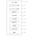
(1)UAV200の外部標定要素の取得
以下、UAV200の外部標定要素(位置と姿勢)を取得する処理手順の一例を図5のフローチャートに沿って説明する。図5の処理を実行に必要なプログラムは、適当な記憶領域や記憶媒体に記憶され、そこから読み出されて実行される。これは、図6の処理についても同じである。
(1) Acquisition of external orientation elements of
まず、TS100のターゲット探索部102により照射される追尾用レーザー光を用いて、UAV200に備えられている反射プリズム202の探索および追尾を行う(ステップS101)。そして、測距用レーザー光を照射により、測距部103においてTS100からUAV200までの距離を計測し(ステップS102)、水平・垂直方向検出部104で水平方向角と垂直方向角を計測する(ステップS103)。それにより、ターゲット位置算出部109において、距離と方向から反射プリズム202の位置が算出され、予め調べられている反射プリズム202とUAV200(レーザースキャナ201)の位置関係によりUAV200の位置(レーザースキャナ201の位置)が算出される(ステップS104)。
First, search and tracking of the reflecting prism 202 provided in the
次に、TS100が備えるレーザースキャナ範囲設定部113により、ステップS104で得られたUAV200の位置を基準として、ターゲット401〜404のうち、少なくとも3つのターゲットを含む領域をレーザースキャン範囲に設定する(ステップS105)。そして、レーザースキャナ112により、ステップS105で設定されたレーザースキャン範囲に対するレーザースキャンを行う(ステップS106)。
Next, the laser scanner range setting unit 113 provided in the
次に、TS100がここまでに取得したレーザースキャンデータは測量データ処理装置300へ送られる。この段階で、測量データ処理装置300は、TS100からターゲット401〜404のスキャンデータを受け付ける。この例では、後処理でレーザースキャナ112が得たレーザースキャンデータと、レーザースキャナ201が得たレーザースキャンデータの処理を行うので、UAV200の飛行終了後にこれら2群のレーザースキャンデータが測量データ処理装置300に送られる。
Next, the laser scan data acquired by the
測量データ処理装置300でレーザースキャナ112のレーザースキャンデータが受け付けられた後、このレーザースキャンデータに基づきターゲット401〜404の曲率半径が算出される。この曲率半径の違いによりターゲット401〜404が個別に識別される。加えて、半球形状であるターゲット401〜404の形状から、曲率中心の位置も得られる(ステップS107)。
After the laser scanning data of the laser scanner 112 is received by the surveying
測量データ処理装置300に備えられているUAV姿勢算出部305は、測位された3つ以上のターゲットの三次元位置より、UAV200の姿勢を示すベクトルを算出する(ステップS108)。この算出されたベクトルを用い、UAV200の地上座標系における姿勢を算出する(ステップS109)。
The UAV
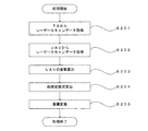
(2)UAV200から取得したレーザースキャン点群を地上座標系に変換
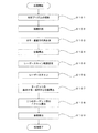
以下、UAV200から取得したレーザースキャン点群を地上座標系に変換する処理手順の一例を図6のフローチャートに沿って説明する。まず、レーザースキャンデータ1取得部301にて、TS100のレーザースキャナ112が得たレーザースキャンデータを取得する(ステップS201)。一方で、レーザースキャンデータ2取得部302は、UAV200のレーザースキャナ201が得たレーザースキャンデータを取得する(ステップS202)。
(2) Conversion of Laser Scan Point Cloud Acquired from
次に、UAV姿勢算出部305にて、レーザースキャンデータ1取得部301が取得したレーザースキャンデータを使い、UAV200の姿勢を算出する(ステップS203)。ここまでは、図5の処理と同じである。
Next, the UAV
次に、座標変換式算出部306にて、UAV姿勢算出部305で算出されたUAV200の姿勢から回転行列RnとベクトルTnを求め、この二つから数1の変換式を算出する(ステップS204)。
Next, the coordinate conversion
最後に、座標変換部307にて、座標変換式算出部306で算出された数1を用いて、三次元座標系から地上座標系への座標変換を行う(ステップS205)。
Finally, the coordinate
(効果)
TS100のターゲット追跡機能およびターゲット測位機能を用いて飛行するUAV200の追跡と測位を行い、同時にTS100のレーザースキャン機能によりUAV200のレーザースキャンを行い、UAV200の姿勢を特定する。この態様によれば、UAV200追跡と同時にUAV200の外部標定要素(位置と姿勢)を高い精度で求めることができる。また、UAV200の外部標定要素が判ることでUAV200に搭載したレーザースキャナ201によるレーザースキャンデータを地上座標系の座標変換し、地上座標系での三次元モデル化が可能となる。
(effect)
The
(変形例1)
ターゲット401〜404を識別する方法として、色情報を利用することもできる。レーザースキャンでは、得られた点群データ(スキャン点群)にカメラが撮影した画像から得られた色データを配色し、各点に色データを付与することができる。このスキャン点群各点の色情報を利用し、ターゲット401〜404の識別を行ってもよい。この場合、予めターゲット401〜404を異なる色に設定しておき、スキャン点群の色データの違いからターゲット401〜404の識別を行う。また、曲率半径と色の違いの両方を用いてターゲットの識別を行う方法も可能である。
(Modification 1)
Color information can also be used as a method for identifying the targets 401 to 404. In laser scanning, color data obtained from an image photographed by a camera can be colored to the obtained point cloud data (scanning point cloud), and color data can be assigned to each point. The targets 401 to 404 may be identified using the color information of each point of the scan point group. In this case, the targets 401 to 404 are set in advance in different colors, and the targets 401 to 404 are identified from the difference in the color data of the scan point group. In addition, a method for identifying a target using both the curvature radius and the color difference is also possible.
(変形例2)
UAV姿勢算出部305におけるUAV200の姿勢を算出する方法として以下の方法もある。この方法では、ターゲット401〜404の少なくとも2つの位置と反射プリズム202の位置とからUAV200の姿勢を求める。この場合、ターゲット401〜404と反射プリズム202のUAV200における位置とその相対位置関係は予めして取得しておく。
(Modification 2)
As a method for calculating the posture of the
ここで、レーザースキャナ112が取得したターゲット401〜404の中の少なくとも2つの三次元位置(XYZ座標系における三次元位置)と、TS100の基本機能であるターゲットの三次元測位機能を用いた反射プリズム202の三次元位置(XYZ座標系における三次元位置)が判ると、UAV200における異なる3点以上の位置が特定される。
Here, a reflecting prism using at least two three-dimensional positions (three-dimensional positions in the XYZ coordinate system) among the targets 401 to 404 acquired by the laser scanner 112 and a target three-dimensional positioning function which is a basic function of the
UAV200における異なる3点以上がXYZ座標系で特定されることで、XYZ座標系(地上座標系)におけるUAV200の姿勢を求めることができる。すなわち、レーザースキャナ112によりターゲット401〜404の少なくとも2つの位置(第1の特定点及び第2の特定点)を特定し、他方でターゲット位置算出部109において反射プリズム202の位置(第3の特定点)を特定する。そして、第1〜第3の特定点の位置からUAV200の姿勢を算出する。
By specifying three or more different points in the
(変形例3)
ターゲット401〜404として反射プリズムを用いる形態も可能である。この場合、各反射プリズムは色付きガラスや蛍光ガラスを用いて構成し、異なる波長の反射特性を有する設定とする。また、TS100のレーザースキャナの受光部は、光学フィルタによって各ターゲットからの異なる波長の反射光を選別して検出できる形態とする。また、ターゲット401〜404と反射プリズム202の反射光が区別できるように、ターゲット401〜404における各反射光の波長と、測距部103で用いる測距光の波長との関係を調整しておく。
(Modification 3)
A form using a reflecting prism as the targets 401 to 404 is also possible. In this case, each reflecting prism is configured using colored glass or fluorescent glass, and is set to have reflection characteristics of different wavelengths. In addition, the light receiving unit of the laser scanner of TS100 is configured to be able to select and detect reflected light of different wavelengths from each target using an optical filter. In addition, the relationship between the wavelength of each reflected light on the targets 401 to 404 and the wavelength of the distance measuring light used in the distance measuring unit 103 is adjusted so that the reflected lights of the targets 401 to 404 and the reflecting prism 202 can be distinguished. .
この場合、ターゲット401〜404の識別は、反射光の波長の違い(あるいは波長スペクトルの違い)を識別することで行われる。ターゲット401〜404の位置は最低3つが必要である点は、反射プリズムの場合と同じである。 In this case, identification of the targets 401 to 404 is performed by identifying a difference in wavelength of reflected light (or a difference in wavelength spectrum). The point that at least three targets 401 to 404 are required is the same as in the case of the reflecting prism.
(変形例4)
UAV200の姿勢を示す反射形状を有する反射部を配置し、この反射部のレーザースキャンデータからUAV200の姿勢を検出する形態も可能である。この場合、当該反射部をレーザースキャンによって他の部分から識別できる反射特性の部材で構成する(塗装や表面処理でもよい)。UAV200の姿勢を示す反射形状としては、矢印、三角形等の形状の方向が判別し易い形状が挙げられる。この技術については、例えば特願2017−137832号に記載された内容が参考となる。
(Modification 4)
A configuration is also possible in which a reflection part having a reflection shape indicating the attitude of the
(変形例5)
TS100は、カメラ101によってUAV200を捕捉し、撮影する機能を有する。この画像の解析結果をUAV200の姿勢を算出に利用することもできる。
(Modification 5)
The
(変形例6)
UAV200の姿勢をTS100の側で検出する方法として、UAV200の形状そのものを利用する形態も可能である。例えば、図1のUAV200は、本体中央部から四方に十字状のアーム405が伸び、その先端にモータとプロペラが配された構造を有している。この十字型のフレーム構造をレーザースキャン点群から取得し、UAV200の水平面からの傾きを検出する。
(Modification 6)
As a method for detecting the posture of the
以下、具体的な処理の手順の一例を説明する。以下説明する処理は、測量データ処理装置300のUAV姿勢算出部305で行われる。
Hereinafter, an example of a specific processing procedure will be described. The process described below is performed by the UAV
まず、予めUAV200の形状に係る基準データを取得しておく。そして、TS100のレーザースキャナ112が取得したレーザースキャン点群から上記基準データにフィッティングする点群データを抽出する。
First, reference data relating to the shape of the
次に、抽出したUAV200にフィッティングした点群データの姿勢を求める。例えば、UAV200の十字構造の腕を構成する点群にフィッティングする平面の方程式を求め、この平面の水平面に対する傾きを求める。この際、UAV200の前後または左右が判別できれば、UAV200の姿勢が求まる。
Next, the posture of the point cloud data fitted to the extracted
この場合、UAV200の十字形状が前後および/または左右においで非対称な形状であれば、レーザースキャンデータからUAV200の前後が識別でき、UAV200の姿勢が完全に求まる。仮に、UAV200の十字形状が非対称な形状でない場合、UAV200内蔵のIMUや方位センサからUAV200の概略の姿勢を取得し、先のレーザースキャン点群から得られた姿勢のデータと合わせて、精密なUAV200の姿勢のデータを得る。この場合、UAV200内蔵のIMUや方位センサの精度が高くなくてもIMUや方位センサの出力から大凡の向きが判れば、レーザースキャンデータからUAV200の姿勢を高精度に求めることができる。
In this case, if the cross shape of the
上記のUAVの形状を利用した方法では、UAVの反射点が特定できれば、少なくとも3点からの反射でUAVの姿勢を算出できる。 In the above method using the UAV shape, if the UAV reflection point can be specified, the UAV posture can be calculated by reflection from at least three points.
なお、UAVの機体本体からのレーザースキャン反射光を利用したUAVの姿勢の計測は、図1に例示した形状に限定されず、他の形状であっても実施可能である。またこの技術は、本明細書で開示するターゲットを用いたUAVの姿勢計測技術と組み合わせて利用することも可能である。 Note that the measurement of the posture of the UAV using the laser scan reflected light from the UAV body is not limited to the shape illustrated in FIG. 1, and can be performed with other shapes. This technique can also be used in combination with the UAV attitude measurement technique using the target disclosed in this specification.
また、UAV200からのレーザースキャン反射光を確実に得るために、UAV200の少なくとも下面に、使用するレーザースキャン光を反射し易い塗装やコーティングを行ってもよい。
Further, in order to reliably obtain laser scan reflected light from the
(変形例7)
TS100の側でUAV200の姿勢を算出する他の例を説明する。この例で説明する処理は、測量データ処理装置300のUAV姿勢算出部305で行われる。
(Modification 7)
Another example of calculating the attitude of the
図7には、UAV200に空撮を行うためのカメラ203を搭載された例が示されている。この例では、UAV200の下部に棒状の支柱204が固定され、この支柱の先端にカメラ203が固定されている。また、支柱204の途中には、L字形状の分岐アーム205が固定され、その先端にはTS100からの追尾光と測距光を反射する反射プリズム202が取り付けられている。この構造では、反射プリズム202は、支柱204の軸線上から外れたオフセット位置にある。ここで、UAV200における反射プリズム202とカメラ203の位置関係、UAV200におけるカメラ203の姿勢の情報は既知であり、予め取得されている。当然、UAV200における支柱204の位置およびその延在方向(延長軸の向き)の情報も既知である。
FIG. 7 shows an example in which a camera 203 for performing aerial photography is mounted on the
この例において、TS100によるUAV200の位置の測定は、反射プリズム202から反射される測距光を用いて行わる。UAV200の姿勢の測定は、上下方向に延在する支柱204をレーザースキャナ112よりレーザースキャンすることで行われる。
In this example, the position of the
以下、支柱204を用いたUAV200の姿勢の計測について説明する。TS100によるUAV200の追尾および測距(測位)が行われている状態で、TS100のレーザースキャナ112により、UAV200を中心とした空域のレーザースキャンを行う。例えば、アーム405の長さが50cm程度である場合に、反射プリズム202を中心とした半径1〜2m程度の空域のレーザースキャンがレーザースキャナ112により行われる。
Hereinafter, the measurement of the posture of the
ここで得たレーザースキャン点群から、支柱204の点群データを抽出する。この処理では、まずレーザースキャンデータから鉛直方向に延在成分を有する直線状に延在する点群データを探し出す。そして、それを予め取得しておいた、アーム405を含むUAV200の三次元モデルにフィッティングさせ、支柱204の点群データを得る。
Point group data of the
支柱204の点群データを得たら、支柱204の延在方向と鉛直方向との関係から、UAV200の鉛直方向に対する傾きを算出する。ここで、反射プリズム202の三次元位置は、図3のターゲット位置算出部109で算出されているので、支柱204から見た反射プリズム202の方向を算出する。
When the point cloud data of the
UAV200における支柱204と反射プリズム202の位置関係は既知であるので、支柱204から見た反射プリズム204の方向が判ることで、水平方向におけるUAV200に向きが判る。つまり、UAV200の支柱204を回転軸とした回転角度が判る。こうして、反射プリズム202の測位データと、支柱204のレーザースキャンデータとからUAV200の姿勢を算出することができる。
Since the positional relationship between the
支柱204のレーザースキャンデータの代わりに、反射プリズム202の測位データと、4本あるアーム405の少なくとも一つのレーザースキャンデータとからUAV200の姿勢を算出することもできる。この場合、4本のアーム405の中心(図7の場合、この中心の位置は、支柱204の延長線上にある)からオフセットした位置に反射プリズム202があるので、反射プリズム202の位置とアーム204の少なくとも一本のレーザースキャン点群とから、UAV200の向きを算出できる。
The attitude of the
以上述べたように、本例では、UAVが特定の方向に延在した長手形状部材と反射プリズムとを備え、前記反射プリズムは、前記長手形状部材の延在軸の軸線とはずれた位置に配置されている。この構造では、反射プリズムを測距光で測距することで、UAVの測位を行い、長手形状部材をレーザースキャンすることで長手形状部材の姿勢(向き)を検出し、UAVにおける反射プリズムの位置と、長手形状部材の位置および姿勢の関係から、UAVの姿勢を算出する。そして、UAVの姿勢が算出されることで、UAV搭載のレーザースキャナやカメラの外部標定要素が求められる。 As described above, in this example, the UAV includes the long shape member extending in a specific direction and the reflection prism, and the reflection prism is arranged at a position deviated from the axis of the extension shaft of the long shape member. Has been. In this structure, UAV positioning is performed by measuring the reflecting prism with ranging light, and the posture (orientation) of the longitudinal member is detected by laser scanning of the longitudinal member, and the position of the reflecting prism in the UAV is detected. Then, the UAV posture is calculated from the relationship between the position and posture of the longitudinal member. Then, by calculating the posture of the UAV, an external orientation element of the UAV-mounted laser scanner or camera is obtained.
(その他)
以上説明したUAV200の姿勢を求める方法の複数を組み合わせて用いることもできる。本明細書で開示する技術は、IMUを用いる以外の方法でUAVの姿勢を計測できる技術であるが、UAVへのIMUの搭載を排除するものではない。よって、本明細書で開示する技術を用いたUAVの姿勢を計測する技術と、UAVに搭載したIMUによるUAVの姿勢を計測する技術とを組み合わせて利用することも可能である。
(Other)
A plurality of methods for obtaining the attitude of the
例えば、UAV搭載のIMUによる姿勢の計測を主とし、それを補助あるいは補完する技術として、本明細書で開示する方法を用いる形態も可能である。一般にIMUは、姿勢の急激な変化は比較的好感度に検出するが、姿勢が緩やかに変化した場合の検出感度は相対的に低い。この傾向は、低価格なIMU程顕著である。そこで、細かい姿勢の変化はIMUで検出し、特定の時間間隔における姿勢の絶対値の検出をレーザースキャナ112によるターゲット401〜404の識別と位置の特定により行う方法を採用することもできる。 For example, a form using the method disclosed in this specification is also possible as a technique that mainly measures posture by an IMU equipped with UAV and assists or complements it. In general, the IMU detects a sudden change in posture with a relatively good sensitivity, but the detection sensitivity when the posture changes gradually is relatively low. This tendency is more conspicuous as IMU has a lower price. Therefore, it is also possible to adopt a method in which a fine change in posture is detected by the IMU, and the absolute value of the posture at a specific time interval is detected by identifying the target 401 to 404 and specifying the position by the laser scanner 112.
また例えば、TS100によるUAV200の追尾が行われる状態では、TS100を用いたUAV200の位置と姿勢の計測を行い、TS100によるUAV200の追尾ができない状態やTS100からのUAV200のレーザースキャンができない状態において、UAV200搭載のGNSS装置によるUAV200の測位およびUAV200搭載のIMUによるUAV200の姿勢の計測を行う形態も可能である。
Also, for example, in the state where the
また、UAV200が搭載したGNSS位置特定装置を用いてUAV200の姿勢の計測を行う方法と本明細書で開示したレーザースキャナ112によるUAV200の姿勢の計測技術とを組み合わせる形態も可能である。
Further, it is possible to combine the method for measuring the attitude of the
Claims (11)
前記レーザースキャンデータに基づき、前記飛行する前記航空機の前記第1の座標系での姿勢を算出する姿勢算出部と
を備え、
前記姿勢は、前記レーザースキャンデータに基づき特定された前記航空機における複数の位置に基づいて算出されるデータ処理装置。 A laser scan data acquisition unit for acquiring laser scan data obtained by irradiating a flying aircraft with laser scan light from a laser scanner fixed in a first coordinate system;
An attitude calculation unit that calculates an attitude of the flying aircraft in the first coordinate system based on the laser scan data;
The attitude is a data processing device that is calculated based on a plurality of positions in the aircraft specified based on the laser scan data.
前記レーザースキャンデータは、前記航空機が備えた識別可能な複数のターゲットを対象としたレーザースキャンにより得られる請求項1に記載のデータ処理装置。 The aircraft includes a plurality of identifiable targets;
The data processing apparatus according to claim 1, wherein the laser scan data is obtained by laser scanning of a plurality of identifiable targets provided in the aircraft.
前記複数のターゲットの識別が前記曲面の曲率半径の違いに基づいて行われる請求項2または3に記載のデータ処理装置。 The plurality of targets have curved reflecting surfaces,
The data processing apparatus according to claim 2 or 3, wherein the plurality of targets are identified based on a difference in curvature radius of the curved surface.
前記複数のターゲットに含まれる2以上のターゲットが含まれる範囲をレーザースキャン範囲として設定するスキャン範囲設定部を備える請求項2〜6のいずれか一項に記載のデータ処理装置。 Based on the position of the aircraft acquired by a position data acquisition unit that acquires data of the position of the aircraft in the first coordinate system,
The data processing apparatus according to claim 2, further comprising a scan range setting unit that sets a range including two or more targets included in the plurality of targets as a laser scan range.
前記第1の座標系における前記航空機の位置と前記複数のターゲットに含まれる2以上のターゲットの位置とに基づいて前記姿勢が算出される請求項2〜7の何れか一項に記載のデータ処理装置。 A position data acquisition unit that acquires data of the position of the aircraft in the first coordinate system;
The data processing according to any one of claims 2 to 7, wherein the attitude is calculated based on a position of the aircraft in the first coordinate system and positions of two or more targets included in the plurality of targets. apparatus.
前記レーザースキャンデータに基づき、前記飛行する前記航空機の前記第1の座標系での姿勢を算出する姿勢算出ステップと
を備え、
前記姿勢は、前記レーザースキャンデータに基づき特定された前記航空機における複数の位置に基づいて算出されるデータ処理方法。 A laser scan data acquisition step of acquiring laser scan data by irradiating a flying aircraft with laser scan light from a laser scanner fixed in a first coordinate system;
An attitude calculation step of calculating an attitude of the flying aircraft in the first coordinate system based on the laser scan data,
The attitude is calculated based on a plurality of positions in the aircraft specified based on the laser scan data.
コンピュータを
飛行する航空機に第1の座標系に固定されたレーザースキャナからレーザースキャン光を照射することで得られたレーザースキャンデータを取得するレーザースキャンデータ取得部と、
前記レーザースキャンデータに基づき、前記飛行する前記航空機の前記第1の座標系での姿勢を算出する姿勢算出部と
を備え、
前記姿勢は、前記レーザースキャンデータに基づき特定された前記航空機における複数の位置に基づいて算出されるデータ処理装置として機能させるためのデータ処理用プログラム。 A program that is read and executed by a computer,
A laser scan data acquisition unit for acquiring laser scan data obtained by irradiating an aircraft flying on a computer with laser scan light from a laser scanner fixed in a first coordinate system;
An attitude calculation unit that calculates an attitude of the flying aircraft in the first coordinate system based on the laser scan data;
A program for data processing for causing the posture to function as a data processing device calculated based on a plurality of positions in the aircraft specified based on the laser scan data.
Priority Applications (2)
| Application Number | Priority Date | Filing Date | Title |
|---|---|---|---|
| JP2017178831A JP7025156B2 (en) | 2017-09-19 | 2017-09-19 | Data processing equipment, data processing method and data processing program |
| US16/129,960 US10969493B2 (en) | 2017-09-19 | 2018-09-13 | Data processing device, data processing method, and data processing program |
Applications Claiming Priority (1)
| Application Number | Priority Date | Filing Date | Title |
|---|---|---|---|
| JP2017178831A JP7025156B2 (en) | 2017-09-19 | 2017-09-19 | Data processing equipment, data processing method and data processing program |
Publications (2)
| Publication Number | Publication Date |
|---|---|
| JP2019053003A true JP2019053003A (en) | 2019-04-04 |
| JP7025156B2 JP7025156B2 (en) | 2022-02-24 |
Family
ID=65720060
Family Applications (1)
| Application Number | Title | Priority Date | Filing Date |
|---|---|---|---|
| JP2017178831A Active JP7025156B2 (en) | 2017-09-19 | 2017-09-19 | Data processing equipment, data processing method and data processing program |
Country Status (2)
| Country | Link |
|---|---|
| US (1) | US10969493B2 (en) |
| JP (1) | JP7025156B2 (en) |
Cited By (2)
| Publication number | Priority date | Publication date | Assignee | Title |
|---|---|---|---|---|
| JP2021089246A (en) * | 2019-12-06 | 2021-06-10 | 三菱電機株式会社 | Alignment measuring system, information processing device, alignment measuring method, and program |
| JP2021528647A (en) * | 2018-06-22 | 2021-10-21 | サウスウェスト リサーチ インスティテュート | Positioning system and method |
Families Citing this family (8)
| Publication number | Priority date | Publication date | Assignee | Title |
|---|---|---|---|---|
| JP2020203664A (en) * | 2019-03-29 | 2020-12-24 | 株式会社トプコン | Flight control system for unmanned aerial vehicle and topography measuring system |
| JP7313998B2 (en) | 2019-09-18 | 2023-07-25 | 株式会社トプコン | Survey data processing device, survey data processing method and program for survey data processing |
| CN111811339B (en) * | 2020-06-15 | 2021-07-13 | 北京理工大学 | Aircraft laser guidance control system and method using ground laser indicator |
| CN112083434B (en) * | 2020-09-09 | 2023-12-29 | 上海有个机器人有限公司 | Laser-based robot detection method and device |
| CN112379390A (en) * | 2020-11-18 | 2021-02-19 | 成都通甲优博科技有限责任公司 | Pose measurement method, device and system based on heterogeneous data and electronic equipment |
| JP2022149716A (en) * | 2021-03-25 | 2022-10-07 | 株式会社トプコン | Survey system |
| CN113419251B (en) * | 2021-05-17 | 2023-07-18 | 重庆大学 | Gesture recognition, coding and decoding and communication method based on laser reflection |
| CN114526634A (en) * | 2022-02-22 | 2022-05-24 | 哈尔滨工业大学 | Continuous wave semi-active laser seeker system |
Citations (9)
| Publication number | Priority date | Publication date | Assignee | Title |
|---|---|---|---|---|
| US4047816A (en) * | 1976-06-18 | 1977-09-13 | The United States Of America As Represented By The Secretary Of The Army | Attitude determination using two transmitter/receiver stations and skewed reflectors |
| US4964722A (en) * | 1988-08-29 | 1990-10-23 | The United States Of America As Represented By The Administrator Of The National Aeronautics And Space Administration | Remote object configuration/orientation determination |
| JPH05170191A (en) * | 1991-12-19 | 1993-07-09 | Mitsubishi Heavy Ind Ltd | Landing guidance sensor system |
| JP2000171559A (en) * | 1998-12-07 | 2000-06-23 | Nec Corp | Method and system for tracking and measurement of aircraft |
| JP2000227309A (en) * | 1999-02-04 | 2000-08-15 | Olympus Optical Co Ltd | Three-dimensional position posture sensing device |
| JP2006242943A (en) * | 2005-02-04 | 2006-09-14 | Canon Inc | Position attitude measuring method and device |
| JP2006284385A (en) * | 2005-03-31 | 2006-10-19 | Nec Toshiba Space Systems Ltd | Reference station system for gps satellite |
| JP2012053004A (en) * | 2010-09-03 | 2012-03-15 | Ihi Corp | Three-dimensional-point group synthesis method |
| JP2017144784A (en) * | 2016-02-15 | 2017-08-24 | 株式会社トプコン | Flight plan creation method and flight body guidance system |
Family Cites Families (21)
| Publication number | Priority date | Publication date | Assignee | Title |
|---|---|---|---|---|
| JPS5124319B2 (en) | 1972-11-11 | 1976-07-23 | ||
| JPS5686407A (en) | 1979-12-15 | 1981-07-14 | Nitto Electric Ind Co | Transparent conductive film and method of manufacturing same |
| US4735508A (en) * | 1986-06-02 | 1988-04-05 | Honeywell Inc. | Method and apparatus for measuring a curvature of a reflective surface |
| EP2041515A4 (en) | 2006-07-13 | 2009-11-11 | Velodyne Acoustics Inc | High definition lidar system |
| US8767190B2 (en) | 2006-07-13 | 2014-07-01 | Velodyne Acoustics, Inc. | High definition LiDAR system |
| JP5263804B2 (en) | 2007-04-20 | 2013-08-14 | 株式会社トプコン | Multipoint measuring method and surveying device |
| JP5124319B2 (en) | 2008-03-21 | 2013-01-23 | 株式会社トプコン | Surveying instrument, surveying system, measuring object detection method, and measuring object detection program |
| JP5688876B2 (en) | 2008-12-25 | 2015-03-25 | 株式会社トプコン | Calibration method for laser scanner measurement system |
| US8386095B2 (en) | 2009-04-02 | 2013-02-26 | Honeywell International Inc. | Performing corrective action on unmanned aerial vehicle using one axis of three-axis magnetometer |
| DE112010004767T5 (en) | 2009-12-11 | 2013-01-24 | Kabushiki Kaisha Topcon | Point cloud data processing device, point cloud data processing method and point cloud data processing program |
| JP5170191B2 (en) | 2010-09-16 | 2013-03-27 | 株式会社デンソー | Low pressure EGR device |
| JP5725922B2 (en) | 2011-03-25 | 2015-05-27 | 株式会社トプコン | Surveying system, surveying pole used in this surveying system, and portable wireless transceiver used in this surveying system |
| JP5711039B2 (en) | 2011-04-27 | 2015-04-30 | 株式会社トプコン | 3D point cloud position data processing apparatus, 3D point cloud position data processing method, 3D point cloud position data processing system, and program |
| JP5963353B2 (en) | 2012-08-09 | 2016-08-03 | 株式会社トプコン | Optical data processing apparatus, optical data processing system, optical data processing method, and optical data processing program |
| US9111444B2 (en) * | 2012-10-31 | 2015-08-18 | Raytheon Company | Video and lidar target detection and tracking system and method for segmenting moving targets |
| US10132928B2 (en) | 2013-05-09 | 2018-11-20 | Quanergy Systems, Inc. | Solid state optical phased array lidar and method of using same |
| US9613539B1 (en) * | 2014-08-19 | 2017-04-04 | Amazon Technologies, Inc. | Damage avoidance system for unmanned aerial vehicle |
| KR20180026470A (en) * | 2015-07-29 | 2018-03-12 | 퀄컴 인코포레이티드 | Angle and position detection using arrays of antennas |
| CN113238581A (en) * | 2016-02-29 | 2021-08-10 | 星克跃尔株式会社 | Method and system for flight control of unmanned aerial vehicle |
| US10101443B1 (en) * | 2016-12-02 | 2018-10-16 | Amazon Technologies, Inc. | Airframe-embedded ultrasonic transducers |
| JP6773573B2 (en) | 2017-01-25 | 2020-10-21 | 株式会社トプコン | Positioning device, position identification method, position identification system, position identification program, unmanned aerial vehicle and unmanned aerial vehicle identification target |
-
2017
- 2017-09-19 JP JP2017178831A patent/JP7025156B2/en active Active
-
2018
- 2018-09-13 US US16/129,960 patent/US10969493B2/en active Active
Patent Citations (9)
| Publication number | Priority date | Publication date | Assignee | Title |
|---|---|---|---|---|
| US4047816A (en) * | 1976-06-18 | 1977-09-13 | The United States Of America As Represented By The Secretary Of The Army | Attitude determination using two transmitter/receiver stations and skewed reflectors |
| US4964722A (en) * | 1988-08-29 | 1990-10-23 | The United States Of America As Represented By The Administrator Of The National Aeronautics And Space Administration | Remote object configuration/orientation determination |
| JPH05170191A (en) * | 1991-12-19 | 1993-07-09 | Mitsubishi Heavy Ind Ltd | Landing guidance sensor system |
| JP2000171559A (en) * | 1998-12-07 | 2000-06-23 | Nec Corp | Method and system for tracking and measurement of aircraft |
| JP2000227309A (en) * | 1999-02-04 | 2000-08-15 | Olympus Optical Co Ltd | Three-dimensional position posture sensing device |
| JP2006242943A (en) * | 2005-02-04 | 2006-09-14 | Canon Inc | Position attitude measuring method and device |
| JP2006284385A (en) * | 2005-03-31 | 2006-10-19 | Nec Toshiba Space Systems Ltd | Reference station system for gps satellite |
| JP2012053004A (en) * | 2010-09-03 | 2012-03-15 | Ihi Corp | Three-dimensional-point group synthesis method |
| JP2017144784A (en) * | 2016-02-15 | 2017-08-24 | 株式会社トプコン | Flight plan creation method and flight body guidance system |
Cited By (4)
| Publication number | Priority date | Publication date | Assignee | Title |
|---|---|---|---|---|
| JP2021528647A (en) * | 2018-06-22 | 2021-10-21 | サウスウェスト リサーチ インスティテュート | Positioning system and method |
| JP7364171B2 (en) | 2018-06-22 | 2023-10-18 | サウスウェスト リサーチ インスティテュート | Position measurement system and method |
| JP2021089246A (en) * | 2019-12-06 | 2021-06-10 | 三菱電機株式会社 | Alignment measuring system, information processing device, alignment measuring method, and program |
| JP7345377B2 (en) | 2019-12-06 | 2023-09-15 | 三菱電機株式会社 | Alignment measurement system, information processing device, alignment measurement method and program |
Also Published As
| Publication number | Publication date |
|---|---|
| US10969493B2 (en) | 2021-04-06 |
| US20190086548A1 (en) | 2019-03-21 |
| JP7025156B2 (en) | 2022-02-24 |
Similar Documents
| Publication | Publication Date | Title |
|---|---|---|
| JP7025156B2 (en) | Data processing equipment, data processing method and data processing program | |
| US10234278B2 (en) | Aerial device having a three-dimensional measurement device | |
| CN113029117B (en) | Flight sensor | |
| CN110573830B (en) | Calibration method of laser sensor | |
| US20190079522A1 (en) | Unmanned aerial vehicle having a projector and being tracked by a laser tracker | |
| JP6843773B2 (en) | Environmental scanning and unmanned aerial vehicle tracking | |
| JP6884003B2 (en) | Unmanned aerial vehicle tracking equipment, unmanned aerial vehicle tracking methods, unmanned aerial vehicle tracking systems and programs | |
| US8583296B2 (en) | Low-altitude altimeter and method | |
| JP7007137B2 (en) | Information processing equipment, information processing methods and programs for information processing | |
| JP6773573B2 (en) | Positioning device, position identification method, position identification system, position identification program, unmanned aerial vehicle and unmanned aerial vehicle identification target | |
| US10527423B1 (en) | Fusion of vision and depth sensors for navigation in complex environments | |
| JP6745169B2 (en) | Laser measuring system and laser measuring method | |
| KR102239562B1 (en) | Fusion system between airborne and terrestrial observation data | |
| US10859511B2 (en) | Mobile imaging of an object using penetrating radiation | |
| JP2016080572A (en) | Laser measurement system | |
| US20160299229A1 (en) | Method and system for detecting objects | |
| US20180172833A1 (en) | Laser repeater | |
| JP6934367B2 (en) | Positioning device, position measuring method and position measuring program | |
| US20210229810A1 (en) | Information processing device, flight control method, and flight control system | |
| KR20160118558A (en) | Lidar system | |
| WO2022256976A1 (en) | Method and system for constructing dense point cloud truth value data and electronic device | |
| CN112146627B (en) | Aircraft imaging system using projection patterns on featureless surfaces | |
| WO2018088991A1 (en) | Lidar system providing a conic scan | |
| KR101181742B1 (en) | Apparatus and method for land-use map renewel | |
| Valerievich et al. | Experimental assessment of the distance measurement accuracy using the active-pulse television measuring system and a digital terrain model |
Legal Events
| Date | Code | Title | Description |
|---|---|---|---|
| A621 | Written request for application examination |
Free format text: JAPANESE INTERMEDIATE CODE: A621 Effective date: 20200916 |
|
| A131 | Notification of reasons for refusal |
Free format text: JAPANESE INTERMEDIATE CODE: A131 Effective date: 20210608 |
|
| A521 | Request for written amendment filed |
Free format text: JAPANESE INTERMEDIATE CODE: A523 Effective date: 20210806 |
|
| TRDD | Decision of grant or rejection written | ||
| A01 | Written decision to grant a patent or to grant a registration (utility model) |
Free format text: JAPANESE INTERMEDIATE CODE: A01 Effective date: 20220201 |
|
| A61 | First payment of annual fees (during grant procedure) |
Free format text: JAPANESE INTERMEDIATE CODE: A61 Effective date: 20220210 |
|
| R150 | Certificate of patent or registration of utility model |
Ref document number: 7025156 Country of ref document: JP Free format text: JAPANESE INTERMEDIATE CODE: R150 |