JP2017518909A - Active pedestrian protection system - Google Patents
Active pedestrian protection system Download PDFInfo
- Publication number
- JP2017518909A JP2017518909A JP2016542989A JP2016542989A JP2017518909A JP 2017518909 A JP2017518909 A JP 2017518909A JP 2016542989 A JP2016542989 A JP 2016542989A JP 2016542989 A JP2016542989 A JP 2016542989A JP 2017518909 A JP2017518909 A JP 2017518909A
- Authority
- JP
- Japan
- Prior art keywords
- vehicle
- pedestrian
- interface
- providing
- deployment mechanism
- Prior art date
- Legal status (The legal status is an assumption and is not a legal conclusion. Google has not performed a legal analysis and makes no representation as to the accuracy of the status listed.)
- Pending
Links
Images


Classifications
-
- B—PERFORMING OPERATIONS; TRANSPORTING
- B60—VEHICLES IN GENERAL
- B60R—VEHICLES, VEHICLE FITTINGS, OR VEHICLE PARTS, NOT OTHERWISE PROVIDED FOR
- B60R21/00—Arrangements or fittings on vehicles for protecting or preventing injuries to occupants or pedestrians in case of accidents or other traffic risks
- B60R21/34—Protecting non-occupants of a vehicle, e.g. pedestrians
- B60R21/36—Protecting non-occupants of a vehicle, e.g. pedestrians using airbags
-
- B—PERFORMING OPERATIONS; TRANSPORTING
- B60—VEHICLES IN GENERAL
- B60R—VEHICLES, VEHICLE FITTINGS, OR VEHICLE PARTS, NOT OTHERWISE PROVIDED FOR
- B60R19/00—Wheel guards; Radiator guards, e.g. grilles; Obstruction removers; Fittings damping bouncing force in collisions
- B60R19/02—Bumpers, i.e. impact receiving or absorbing members for protecting vehicles or fending off blows from other vehicles or objects
- B60R19/24—Arrangements for mounting bumpers on vehicles
- B60R19/38—Arrangements for mounting bumpers on vehicles adjustably or movably mounted, e.g. horizontally displaceable for securing a space between parked vehicles
- B60R19/40—Arrangements for mounting bumpers on vehicles adjustably or movably mounted, e.g. horizontally displaceable for securing a space between parked vehicles in the direction of an obstacle before a collision, or extending during driving of the vehicle, i.e. to increase the energy absorption capacity of the bumper
-
- B—PERFORMING OPERATIONS; TRANSPORTING
- B60—VEHICLES IN GENERAL
- B60R—VEHICLES, VEHICLE FITTINGS, OR VEHICLE PARTS, NOT OTHERWISE PROVIDED FOR
- B60R21/00—Arrangements or fittings on vehicles for protecting or preventing injuries to occupants or pedestrians in case of accidents or other traffic risks
- B60R21/01—Electrical circuits for triggering passive safety arrangements, e.g. airbags, safety belt tighteners, in case of vehicle accidents or impending vehicle accidents
- B60R21/013—Electrical circuits for triggering passive safety arrangements, e.g. airbags, safety belt tighteners, in case of vehicle accidents or impending vehicle accidents including means for detecting collisions, impending collisions or roll-over
- B60R21/0134—Electrical circuits for triggering passive safety arrangements, e.g. airbags, safety belt tighteners, in case of vehicle accidents or impending vehicle accidents including means for detecting collisions, impending collisions or roll-over responsive to imminent contact with an obstacle, e.g. using radar systems
-
- B—PERFORMING OPERATIONS; TRANSPORTING
- B60—VEHICLES IN GENERAL
- B60R—VEHICLES, VEHICLE FITTINGS, OR VEHICLE PARTS, NOT OTHERWISE PROVIDED FOR
- B60R21/00—Arrangements or fittings on vehicles for protecting or preventing injuries to occupants or pedestrians in case of accidents or other traffic risks
- B60R21/01—Electrical circuits for triggering passive safety arrangements, e.g. airbags, safety belt tighteners, in case of vehicle accidents or impending vehicle accidents
- B60R21/013—Electrical circuits for triggering passive safety arrangements, e.g. airbags, safety belt tighteners, in case of vehicle accidents or impending vehicle accidents including means for detecting collisions, impending collisions or roll-over
- B60R21/0136—Electrical circuits for triggering passive safety arrangements, e.g. airbags, safety belt tighteners, in case of vehicle accidents or impending vehicle accidents including means for detecting collisions, impending collisions or roll-over responsive to actual contact with an obstacle, e.g. to vehicle deformation, bumper displacement or bumper velocity relative to the vehicle
-
- B—PERFORMING OPERATIONS; TRANSPORTING
- B60—VEHICLES IN GENERAL
- B60R—VEHICLES, VEHICLE FITTINGS, OR VEHICLE PARTS, NOT OTHERWISE PROVIDED FOR
- B60R21/00—Arrangements or fittings on vehicles for protecting or preventing injuries to occupants or pedestrians in case of accidents or other traffic risks
- B60R21/34—Protecting non-occupants of a vehicle, e.g. pedestrians
-
- B—PERFORMING OPERATIONS; TRANSPORTING
- B60—VEHICLES IN GENERAL
- B60R—VEHICLES, VEHICLE FITTINGS, OR VEHICLE PARTS, NOT OTHERWISE PROVIDED FOR
- B60R19/00—Wheel guards; Radiator guards, e.g. grilles; Obstruction removers; Fittings damping bouncing force in collisions
- B60R19/02—Bumpers, i.e. impact receiving or absorbing members for protecting vehicles or fending off blows from other vehicles or objects
- B60R19/24—Arrangements for mounting bumpers on vehicles
- B60R19/38—Arrangements for mounting bumpers on vehicles adjustably or movably mounted, e.g. horizontally displaceable for securing a space between parked vehicles
Landscapes
- Engineering & Computer Science (AREA)
- Mechanical Engineering (AREA)
- Radar, Positioning & Navigation (AREA)
- Remote Sensing (AREA)
- Superstructure Of Vehicle (AREA)
- Body Structure For Vehicles (AREA)
Abstract
移動車両との接触時に歩行者を衝撃緩和するための方法。当該方法は、接触時に前記歩行者を衝撃緩和するように構成されるエネルギー吸収歩行者インタフェースを設けるステップと、前記インタフェースに動作可能に結合され、格納位置と展開位置との間で前記インタフェースを移動させるように構成されるインタフェース展開機構を設けるステップと、前記車両が移動中であるときに、かつ、前記歩行者と前記車両との間の接触前に、前記歩行者インタフェースを前記展開位置まで移動させるステップとを含む。A method for cushioning pedestrians when in contact with a moving vehicle. The method includes providing an energy absorbing pedestrian interface configured to cushion the pedestrian upon contact, and operably coupled to the interface to move the interface between a retracted position and a deployed position. Providing an interface deployment mechanism configured to move the pedestrian interface to the deployed position when the vehicle is moving and before contact between the pedestrian and the vehicle. And a step of causing.
Description
[関連出願の相互参照]
本出願は、2013年12月31日に出願された米国仮出願第61/922,705号の利益を主張し、その開示は、その全体が参照により本明細書に組み込まれる。本出願は、また、2014年12月1日に出願された米国出願第14/557,385号の一部継続出願であり、その利益を主張し、米国出願第14/557,385号は、共に2013年11月29日に出願された米国仮出願第61/910,270号及び第61/910,265号の利益を主張し、それらの開示は、その全体が参照により本明細書に組み込まれる。
[Cross-reference of related applications]
This application claims the benefit of US Provisional Application No. 61 / 922,705, filed December 31, 2013, the disclosure of which is incorporated herein by reference in its entirety. This application is also a continuation-in-part of U.S. Application No. 14 / 557,385, filed December 1, 2014, and claims its benefit, U.S. Application No. 14 / 557,385 is Both claim the benefit of US Provisional Application Nos. 61 / 910,270 and 61 / 910,265 filed Nov. 29, 2013, the disclosures of which are hereby incorporated by reference in their entirety. It is.
[発明の背景]
本発明は、移動車両と接触するときに歩行者に対する損傷を防止するのに役立つ車両搭載式安全システムに関する。
[Background of the invention]
The present invention relates to a vehicle-mounted safety system that helps prevent damage to pedestrians when in contact with a moving vehicle.
現代の車両は、センサ及び他の機構の組合せを使用して、歩行者との車両衝突を事前検知し確認する。センサが歩行者との物理的衝突を確認すると、消耗型保護デバイスの急速な展開が起こる。このアプローチの失敗の原因は、(1)接触前検知が高価であること、(2)接触前検知が、保護デバイスの事前展開(すなわち、接触事象において所定配置になるような接触前の展開)を約束するのに十分に信頼性がなく又は費用効果的でないこと、(3)衝突を確認するため(事前検知あり又は事前検知なしでの)物理的接触検知が必要とされることである。 Modern vehicles use a combination of sensors and other mechanisms to pre-detect and confirm vehicle collisions with pedestrians. When the sensor confirms a physical collision with the pedestrian, rapid deployment of the consumable protection device occurs. The causes of this approach failure are (1) pre-contact detection is expensive, (2) pre-contact detection is pre-deployment of the protective device (ie, pre-contact deployment such that it is in place in a contact event). (3) Physical contact detection (with or without pre-detection) is required to confirm a collision.
したがって、安全システムの動作以外の目的で車両内に存在する、センサ及びコントローラと動作可能に結合可能なコンポーネントを含む歩行者安全システムについての必要性が存在する。接触前に、歩行者との接触のためのエネルギー吸収デバイスを事前配置するため、再設定可能でかつ動作可能であるシステムについての必要性が同様に存在する。 Accordingly, there is a need for a pedestrian safety system that includes components that are operatively coupled to sensors and controllers that exist in a vehicle for purposes other than the operation of the safety system. There is also a need for a system that is reconfigurable and operable to pre-position an energy absorbing device for contact with a pedestrian prior to contact.
[発明の概要]
本明細書で説明される実施形態の一側面では、移動車両との接触時に歩行者を衝撃緩和(cushioning)するための方法が提供される。方法は、接触時に歩行者を衝撃緩和するように構成されるエネルギー吸収歩行者インタフェースを設けるステップと、当該インタフェースに動作可能に結合され、格納位置と展開位置との間でインタフェースを移動させるように構成されるインタフェース展開機構を設けるステップと、車両が移動中であるときに、かつ、歩行者と車両との間の接触前に、歩行者インタフェースを展開位置まで移動させるステップと、を含む。
[Summary of Invention]
In one aspect of the embodiments described herein, a method is provided for impacting a pedestrian upon contact with a moving vehicle. The method includes providing an energy absorbing pedestrian interface configured to cushion the pedestrian upon contact and operably coupled to the interface to move the interface between a retracted position and a deployed position. Providing a configured interface deployment mechanism; and moving the pedestrian interface to a deployed position when the vehicle is moving and prior to contact between the pedestrian and the vehicle.
本明細書で説明される実施形態の別側面では、歩行者と移動車両との間の接触部からエネルギーを受けるためエネルギー吸収歩行者インタフェースを配置するための方法が提供される。方法は、インタフェースに動作可能に結合され、第1の位置と第2の位置との間でインタフェースを移動させるように構成されるインタフェース展開機構を設けるステップと、第1の所定速度以上で車両が移動しているとき、第1の位置から第2の位置までインタフェースを移動させるステップとを含む。 In another aspect of the embodiments described herein, a method is provided for deploying an energy absorbing pedestrian interface to receive energy from a contact between a pedestrian and a moving vehicle. The method includes providing an interface deployment mechanism operably coupled to the interface and configured to move the interface between a first position and a second position; and when the vehicle is above a first predetermined speed, Moving the interface from the first position to the second position when moving.
本明細書で説明される実施形態の別側面では、能動的歩行者保護システムが提供される。システムは、歩行者と車両との間の衝突事象時に歩行者を衝撃緩和するように構成されるエネルギー吸収歩行者インタフェースと、インタフェースに動作可能に結合され、車両の速度に応答して格納位置と展開位置との間でインタフェースを移動させるように構成される歩行者インタフェース展開機構とを含む。 In another aspect of the embodiments described herein, an active pedestrian protection system is provided. The system includes an energy absorbing pedestrian interface configured to cushion the pedestrian during a collision event between the pedestrian and the vehicle, and a storage position responsive to the vehicle speed and operatively coupled to the interface. And a pedestrian interface deployment mechanism configured to move the interface between deployment locations.
図面は、本明細書で説明される種々の実施形態を示す。
[詳細な説明]
同様の参照数字は、図面の幾つかの図の記述全体を通じて同様の部位を示す。更に、目標値が、本明細書で説明される種々の特徴の寸法について挙げられるかもしれないが、これらの値が製造公差のような因子によってわずかに変動してもよいこと、及び、同様に、こうした変動が、本明細書で説明される実施形態の企図される範囲内にあることが理解される。
[Detailed description]
Like reference numerals indicate like parts throughout the description of several figures of the drawings. Further, target values may be mentioned for the dimensions of the various features described herein, but these values may vary slightly due to factors such as manufacturing tolerances, and similarly It will be understood that such variations are within the contemplated scope of the embodiments described herein.
本明細書で説明される実施形態は、能動的歩行者保護システムに関する。システムは、1以上のエネルギー吸収コンポーネントを搭載し、これらを格納又は非展開構成と展開構成との間で移動させる。エネルギー吸収コンポーネント(複数可)は、歩行者との接触前に、車両の速度に基づいて、展開構成に動かされ、それにより、歩行者との接触前にエネルギー吸収コンポーネント(複数可)を事前配置する。システムはまた、同様に車両の速度に基づいてエネルギー吸収コンポーネント(複数可)を展開構成から格納又は非展開構成に戻す。エネルギー吸収コンポーネント(複数可)は、車両と歩行者との間の接触力を減少させる手助けをするように設計される。 Embodiments described herein relate to an active pedestrian protection system. The system carries one or more energy absorbing components and moves them between a stored or undeployed configuration and a deployed configuration. The energy absorbing component (s) are moved to a deployed configuration based on the vehicle speed prior to contact with the pedestrian, thereby pre-positioning the energy absorbing component (s) prior to contact with the pedestrian To do. The system also returns the energy absorbing component (s) from the deployed configuration to the retracted or undeployed configuration based on the vehicle speed as well. The energy absorbing component (s) are designed to help reduce the contact force between the vehicle and the pedestrian.
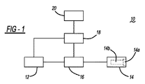
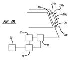
図1は、本明細書で説明される複数の実施形態に従う能動的歩行者保護システム10の概略図を示す。図1に示す実施形態において、保護システム10は、加圧流体源12、加圧流体作動可能なエネルギー吸収機構14、流体源12及びエネルギー吸収機構14に動作可能に結合されたバルブ機構16、並びに、そのバルブ機構16、流体源12、及び車両速度情報源20(例えば、オンボード速度センサ)に動作可能に結合されたコントローラ18を含む。バルブ機構16は、任意の必要な流体流量制御コンポーネント(弁、ソレノイド等を含む)を含んでもよく、コントローラ18によってエネルギー吸収機構14への及びからの流体流量を制御するように動作可能である。コントローラ18は、車両の速度に関する情報に応じてバルブ機構16の動作を制御してもよい。圧力逃がし弁又は他の流体排出機構(図示せず)は、システム圧力が或るレベル超える場合に過剰のシステム圧力を逃がすために、システムに組み込まれてもよい。
FIG. 1 shows a schematic diagram of an active
特定の実施形態において、本明細書で説明される歩行者保護システム10は、車両の構造内に組み込まれる。本明細書で説明される歩行者インタフェースを展開するための機構は、車両製造時に車両に設置される車両コントローラ及び/又はセンサに動作可能に結合されてもよい。
In certain embodiments, the
加圧流体源12は、加圧流体(例えば、圧縮空気、圧縮ガス、又はオイル等の油圧流体)をエネルギー吸収機構14に供給し、機構を、本明細書で説明される方法で作動又は展開させる。流体源12は、ポンプ又は圧縮機(例えばガス圧縮機等)(図示せず)を搭載してもよい(又は、それに動作可能に結合されていてもよい)。流体源は、コントローラにより動作可能であってもよく、これにより、既知の方法で、例えば、ポンプ又は圧縮機内の流れ方向を反転させる方法で、流体源からの流体流の方向を(流体作動可能なエネルギー吸収機構14に向かうように又はそこから離れるように)コントローラ18で制御する。これは、本明細書で説明されるように膨張可能エネルギー吸収部材の反復する膨張及び収縮を可能にする。本明細書で説明される目的に適した電子制御可能なバルブ機構は、種々のベンダーのうちの任意のベンダー(例えば、カルフォルニア州サンホセ(San Jose,CA)のWIC Valve、又は、カルフォルニア州パロアルト(Palo Alto,CA)のSizto Tech Corporation(STC))から取得されてもよい。本明細書で説明される目的に適した加圧流体源(例えば、圧縮機)は、種々のベンダーのうちの任意のベンダー(例えば、ミシガン州グランドブランク(Grand Blank,MI)のACDelco)から取得されてもよい。
The pressurized
コントローラ18は、車両内に既に(例えば、車両製造時に)設置されたシステムコントローラであってよい、又は、コントローラは、専用エネルギー吸収機構コントローラであってよい。エネルギー吸収機構14は、コントローラ18によって、適した1つ(又は複数)の速度センサ20から受信される信号に応じて作動されてもよい。
The
本明細書で説明される実施形態において、歩行者保護システム10は、能動的システムであり、本明細書で説明されるエネルギー吸収機構14は、格納又は非展開状態(例えば、図2A、3A、4A、5B、6A、8A、9A、及び10〜11に示す)から、所定の状態又は状態セットの発生に応じて、歩行者に係合するように設計された完全に展開した状態(例えば、2C、3B、4B、5C、6B、8B、9B、及び11A〜12に示す)に、選択的に展開可能である。エネルギー吸収機構は、車両と歩行者との間の接触の前に(また、接触すると)移動車両内で展開する。
In the embodiments described herein, the
特定の実施形態の動作において、システムは、車両が静止しているとき又は所定の閾値速度V未満の速度で移動しているとき、エネルギー吸収機構が非展開状態にあるままであるように構成される。エネルギー吸収機構は、車両が閾値速度Vに達すると展開する。システムは、車両速度が閾値速度Vを下回るまでエネルギー吸収機構を完全に展開した状態に維持する。 In operation of certain embodiments, the system is configured such that the energy absorbing mechanism remains in an undeployed state when the vehicle is stationary or moving at a speed below a predetermined threshold speed V. The The energy absorbing mechanism is deployed when the vehicle reaches the threshold speed V. The system keeps the energy absorbing mechanism fully deployed until the vehicle speed falls below the threshold speed V.
他の特定の実施形態の動作において、システムは、エネルギー吸収機構が、車両が第1の所定閾値未満の速度で走行しているときに格納又は非展開状態で存在し、更には、第1の所定閾値より大きい第2の所定閾値を超える速度で車両が走行しているときに非展開状態に戻るように構成される。エネルギー吸収機構は、車両が第1の所定閾値を超える速度に達すると展開する。1つの特定の実施形態において、第1の所定閾値は10MPHであり、第2の所定閾値は25MPHである。本明細書で説明される目的のために、コントローラは、車両速度を測定又は計算するために使用可能な任意のセンサ又は他の手段(例えば、速度計又はホイール速度センサ)と動作可能に結合してもよい。エネルギー吸収機構がそれにわたって展開される車両速度の特定の1つ(又は複数)の範囲は、車両製造業者によって決定されてもよい。 In operation of other specific embodiments, the system includes an energy absorption mechanism that is in a retracted or undeployed state when the vehicle is traveling at a speed less than a first predetermined threshold, and further wherein the first The vehicle is configured to return to a non-deployed state when the vehicle is traveling at a speed exceeding a second predetermined threshold value that is greater than the predetermined threshold value. The energy absorbing mechanism is deployed when the vehicle reaches a speed exceeding a first predetermined threshold. In one particular embodiment, the first predetermined threshold is 10 MPH and the second predetermined threshold is 25 MPH. For the purposes described herein, the controller is operably coupled to any sensor or other means (eg, a speedometer or wheel speed sensor) that can be used to measure or calculate vehicle speed. May be. The particular one (or more) range of vehicle speeds over which the energy absorbing mechanism is deployed may be determined by the vehicle manufacturer.
再び図1を参照すると、本明細書で説明される実施形態において、エネルギー吸収機構14は、歩行者インタフェース展開機構(全体的に14bで示される)及び展開機構14bに動作可能に結合された歩行者インタフェース14aを含む。歩行者インタフェース14aは、通常、衝突事象時に展開機構と歩行者との間に介在して、車両−歩行者接触エネルギーの少なくとも一部分を吸収するエネルギー吸収機構の第1の部分になるように配置される。歩行者インタフェースは、同様に、車両−歩行者接触力を展開機構に伝達する媒体の役割をする。歩行者インタフェース14aは、同様に、展開機構14bの作動が格納位置から展開(又は歩行者係合)位置への、又は、展開位置から元の格納位置への歩行者インタフェース14aの移動をもたらすように展開機構14bに結合される。そのため、エネルギー吸収機構14は、車両が静止しているとき、及び/又は、1以上の所定の速度範囲内の速度で走行しているとき、展開前構成又は非展開構成になるように、完全かつ自動的にリセット可能である。
Referring again to FIG. 1, in the embodiment described herein, the
本明細書で説明される、ある実施形態において、歩行者インタフェース14aは、歩行者と車両との間で衝突が起こると歩行者に直接接触するように構築され配置される。歩行者が歩行者インタフェースに接触すると、接触エネルギーは、歩行者インタフェースに、更には(任意に)展開機構に伝達されて、歩行者衝突の緩和を補助する。
In certain embodiments described herein, the
他の実施形態において、歩行者インタフェースは、展開機構に、更には、衝突事象時歩行者と接触し得る車両の別の部分に、動作可能に結合される。展開すると、歩行者インタフェース14aは、展開機構と車両の他の部分との間に存在する。展開機構の作動は、歩行者インタフェースをその展開位置又は状態に展開し、それが、次に、車両の他の部分を、歩行者との接触前に、歩行者係合位置又は構成に動かす。歩行者が車両の他の部分と接触すると、接触エネルギーは、歩行者インタフェースに、更には(任意に)展開機構に伝達されて、歩行者衝突の緩和を補助する。
In other embodiments, the pedestrian interface is operably coupled to the deployment mechanism and also to another part of the vehicle that can contact the pedestrian during a crash event. When deployed, the
歩行者インタフェースは、車両−歩行者接触エネルギーの少なくとも一部分を吸収するように構築される。そのため、歩行者インタフェース14aは、任意の適したエネルギー吸収材料又は材料の組合せ、例えば、発泡材料、ポリマー、ゴム又は他のばね様材料、シリコーン、1以上の金属材料、及び/又は、その他の任意の適した材料又は材料の組合せから形成されてもよい。
The pedestrian interface is constructed to absorb at least a portion of the vehicle-pedestrian contact energy. As such, the
ある実施形態において、歩行者インタフェースは、車両−歩行者接触負荷を、展開機構構造に伝達する、及び/又は、より効果的に分配するように構築され、及び、歩行者インタフェース展開機構に取り付けられ、展開機構構造もまた、車両−歩行者接触エネルギーの一部分を吸収するように構築され得る。 In certain embodiments, the pedestrian interface is constructed and attached to the pedestrian interface deployment mechanism to communicate and / or more effectively distribute vehicle-pedestrian contact loads to the deployment mechanism structure. The deployment mechanism structure can also be constructed to absorb a portion of the vehicle-pedestrian contact energy.
本明細書で説明される複数の実施形態では、歩行者インタフェース展開機構は、車両の速度だけに応答してインタフェースを格納位置と展開位置との間で移動させるように構成される。 In embodiments described herein, the pedestrian interface deployment mechanism is configured to move the interface between a retracted position and a deployed position in response only to vehicle speed.
本明細書で説明される、ある実施形態では(例えば、図2A、3A、及び4Aに示すように)、歩行者インタフェース(及び、任意には関連する展開機構)は、歩行者と接触するように露出した車両の外部の表面に形成されたキャビティ内に入れ子にされる又は受容されるように構築される。歩行者インタフェースの歩行者を向く表面又は外側を向く表面は、また、車両の部分(複数可)であってキャビティがその中に形成され、展開位置にないときには歩行者インタフェースがその中に受容される車両の部分の、外側表面に一致する又は外側表面と同一平面上になるように構築されてもよい。そのため、格納位置において、歩行者インタフェース14aは、車両の全長又は他の外部寸法を増加させない。
In certain embodiments described herein (eg, as shown in FIGS. 2A, 3A, and 4A), the pedestrian interface (and optionally the associated deployment mechanism) is in contact with the pedestrian. It is constructed to be nested or received in a cavity formed on the exterior surface of the vehicle exposed to The pedestrian-facing or outward-facing surface of the pedestrian interface is also part of the vehicle (s) in which the cavity is formed and when not in the deployed position, the pedestrian interface is received therein. The vehicle portion may be constructed to coincide with or be flush with the outer surface. Thus, in the retracted position, the
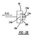
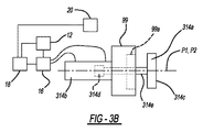
これらの状態の例は、図2A〜2C及び3A〜3Bに示され、これらの図は、車両バンパ99の前を向く表面99b内に形成されたキャビティ99a内に受容される歩行者インタフェース114a、314aを示す。歩行者インタフェース114a、314aがキャビティ99a内に格納状態で受容されると(図2A、3A)、それぞれの歩行者インタフェース114a、314aの最も前の又は歩行者接触表面114c、314cは、車両バンパの最も前の表面99bと同一平面上になる。そのため、格納位置において、歩行者インタフェース114a、314aは、車両の全長を増加させない(すなわち、格納されると、歩行者インタフェース114a、314aは、従来の車両バンパが延在することになる場所を通り越して延在しない)。
Examples of these conditions are shown in FIGS. 2A-2C and 3A-3B, which show a
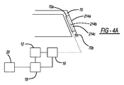
上述した状態の別の例は、図4A〜4Bに示され、ここでは、歩行者インタフェース214aが車両Aピラー70内に形成されるキャビティ70a内に受容される。歩行者インタフェース214aがキャビティ70a内に格納状態で受容されると(図4A)、インタフェース214aの外側又は歩行者接触表面214cは、Aピラーの外側表面70bと同一平面上になる。
Another example of the situation described above is shown in FIGS. 4A-4B, where a
代替の実施形態において、歩行者インタフェースは、歩行者インタフェースがその中に受容される車両部分の外側表面を超えて延在するように構築され、これによれば、車両部分のスタイリングの変更が可能になり、また、歩行者インタフェースを、利用可能な歩行者インタフェースの圧壊空間を増加させるために肉厚化すること、又は、そのエネルギー吸収能力を増加させるために他の方法で変更することが可能になる。 In an alternative embodiment, the pedestrian interface is constructed such that it extends beyond the outer surface of the vehicle portion in which the pedestrian interface is received, thereby allowing for changing the styling of the vehicle portion. And the pedestrian interface can be thickened to increase the crushing space of the available pedestrian interface, or otherwise modified to increase its energy absorption capacity become.
ある実施形態(例えば、図2A〜2C、4A〜4B、及び6A〜6Bに示す実施形態)において、展開機構は、車両の一部分内に形成されたキャビティ内に配置された膨張可能部材又はデバイス(例えば、エアバッグ、ブラダー(bladder)、又は他の膨張可能デバイス)の形態である。歩行者インタフェースは、膨張可能デバイスの前方に配置される部分に取り付けられてもよく、膨張可能な展開機構を膨張させることによって、歩行者との接触前に完全に展開した位置に移動される。歩行者インタフェースは、車両が静止している間、格納位置内にあるままである。歩行者インタフェースが展開される車両速度において、膨張可能デバイスの膨張は、取り付けられたエネルギー吸収機構を、その非展開又は格納位置からその展開位置まで延長する。歩行者インタフェースが格納位置に戻る車両速度において、膨張可能な展開デバイスは、膨張可能デバイスから加圧流体を排出することによって、又は、デバイスを積極的に空にするため流体流の方向を反転させることによって収縮され又は空にされてもよく、これにより、歩行者インタフェースを、元通りにその収納キャビティ内の格納位置に後退させる。 In certain embodiments (e.g., the embodiments shown in FIGS. 2A-2C, 4A-4B, and 6A-6B), the deployment mechanism is an inflatable member or device disposed in a cavity formed in a portion of the vehicle ( For example, in the form of an air bag, bladder, or other inflatable device. The pedestrian interface may be attached to a portion disposed in front of the inflatable device and is moved to a fully deployed position prior to contact with the pedestrian by inflating the inflatable deployment mechanism. The pedestrian interface remains in the retracted position while the vehicle is stationary. At the vehicle speed at which the pedestrian interface is deployed, the expansion of the inflatable device extends the attached energy absorbing mechanism from its undeployed or retracted position to its deployed position. At the vehicle speed at which the pedestrian interface returns to the retracted position, the inflatable deployment device reverses the direction of fluid flow by draining pressurized fluid from the inflatable device or to actively empty the device. May be deflated or emptied, thereby retracting the pedestrian interface back to its storage position within its storage cavity.
膨張可能デバイスの形態の展開機構の例は、図2A〜2Cに示される。図2Aは、格納された膨張前の状態にある展開機構114bを示す。エネルギー吸収機構が作動されると、加圧流体が膨張可能デバイス114bに導入され、デバイスの拡張を引き起こす。膨張可能デバイスが拡張すると、付属するエネルギー吸収歩行者インタフェース114aは、バンパーキャビティ99から出て(図2B)、図2Cに示す完全に展開した位置に移動する。エネルギー吸収機構が停止されると、膨張可能デバイスは、空にされるか又はその他の方法で収縮され、膨張可能部材114bを元通りキャビティ99a内に後退させる。
An example of a deployment mechanism in the form of an inflatable device is shown in FIGS. FIG. 2A shows the
膨張可能デバイスの形態の展開機構の別の例は、図4A〜4Bに示される。図4Aは、格納された膨張前の状態にある展開機構214bを示す。エネルギー吸収機構が作動されると、加圧流体が膨張可能デバイス214bに導入され、デバイスの拡張を引き起こす。膨張可能デバイスが拡張すると、付属するエネルギー吸収歩行者インタフェース214aは、Aピラーキャビティ70aから出て、図4Bに示す完全に展開した位置に移動する。エネルギー吸収機構が停止されると、膨張可能デバイス214bは、空にされるか又はその他の方法で収縮され、膨張可能部材を元通りキャビティ70a内に後退させる。
Another example of a deployment mechanism in the form of an inflatable device is shown in FIGS. FIG. 4A shows the
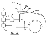
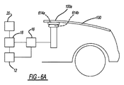
膨張可能デバイスの形態の展開機構の別の例は、図5A及び6A〜6Bに示される。図5Aは、本明細書で説明されるインタフェース展開機構及びエネルギー吸収歩行者インタフェースの一実施形態を使用する歩行者安全システムを搭載する車両の一部分の概略斜視図である。図6Aは、格納された膨張前の状態にある膨張可能な展開機構614bを示す。エネルギー吸収機構が作動されると、加圧流体が膨張可能デバイス614bに導入され、デバイスの拡張を引き起こす。膨張可能デバイスが拡張すると、(膨張可能デバイス614b及び車両フード100の後方部分100aに取り付けられた)エネルギー吸収歩行者インタフェース614aは、図6Bに示す完全に展開した位置に移動する。エネルギー吸収機構が停止されると、膨張可能部材614bは、空にされるか又はその他の方法で収縮され、エネルギー吸収部材614aをその格納位置に戻し、取り付けられたフード後方部分100aをその通常の動作位置に移動させる。
Another example of a deployment mechanism in the form of an inflatable device is shown in Figures 5A and 6A-6B. FIG. 5A is a schematic perspective view of a portion of a vehicle equipped with a pedestrian safety system that uses one embodiment of the interface deployment mechanism and energy absorbing pedestrian interface described herein. FIG. 6A shows the
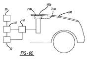
膨張可能デバイスの形態の展開機構の別の例は、図6C〜6Dに示される。図6C〜6Dに示す車両は、フード100の後縁と車両ウインドシールドのベースとの間に配置された可動カウルパネル100bを搭載する。このパネルは、ウインドシールドワイパ及び/又は他のコンポーネントを収容してもよく、また、フード又は車両の別の部分にヒンジ式で又はその他の方法で回転可能に接続されてもよい。図6Cは、格納された膨張前の状態にある膨張可能な展開機構714bを示す。エネルギー吸収機構が作動されると、加圧流体が膨張可能デバイス714bに導入され、デバイスの拡張を引き起こす。膨張可能デバイスが拡張すると、(膨張可能デバイス714b及びカウルパネル100bに取り付けられた)歩行者インタフェース714aは、図6Dに示す完全に展開した位置に移動する。エネルギー吸収機構が停止されると、膨張可能デバイス714bは、空にされるか又はその他の方法で収縮され、エネルギー吸収部材714aをその格納位置に戻し、付属するカウルパネル100bをその通常の動作位置に移動させる。
Another example of a deployment mechanism in the form of an inflatable device is shown in FIGS. The vehicle shown in FIGS. 6C to 6D has a
膨張可能部材は、膨張可能デバイスが所望の方向に膨張又は拡張すること、また同様に、膨張可能デバイスが、空にされると、逆方向に収縮することを保証するのに役立つように構築されてもよい。この構造は、歩行者インタフェースが、展開と展開との間に、格納キャビティに絶えずかつ自動的に再収容されることを保証するのに役立つ。一実施形態において、膨張可能部材は、膨張中に所定の方向に伸長するように構築された伸長可能なアコーデオン又はベローズ様の構造を有する。他の適した構造もまた使用されてもよい。 The inflatable member is constructed to help ensure that the inflatable device expands or expands in the desired direction, and similarly, when the inflatable device is emptied, it contracts in the opposite direction. May be. This structure helps to ensure that the pedestrian interface is constantly and automatically recontained in the storage cavity between deployments. In one embodiment, the inflatable member has an extensible accordion or bellows-like structure constructed to elongate in a predetermined direction during inflation. Other suitable structures may also be used.
膨張可能部材用の加圧流体源(複数可)は、例えば、圧縮機、ポンプ、及び/又は他の既知の要素の動作によってチャージされるリザーバ;膨張可能部材に加圧ガスを直接供給するための及び/又は膨張可能部材からガスを取出すための圧縮機、ポンプ、及び/又は他の既知の要素;又は、任意の他の適した流体源を含んでもよい。個別の加圧流体源が各膨張可能部材に動作可能に結合されてもよい。あるいは、共通の加圧流体源が複数の膨張可能部材に結合されてもよい。 The pressurized fluid source (s) for the inflatable member is, for example, a reservoir that is charged by the operation of a compressor, pump, and / or other known elements; to supply pressurized gas directly to the inflatable member And / or a compressor, pump, and / or other known elements for removing gas from the inflatable member; or any other suitable fluid source. A separate source of pressurized fluid may be operably coupled to each inflatable member. Alternatively, a common source of pressurized fluid may be coupled to multiple inflatable members.
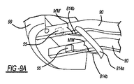
歩行者インタフェースを展開するための展開機構として使用可能な、ある機構が米国出願第14/557,385号に記載され、その開示は参照によりその全体が本明細書に組み込まれる。図8A〜9Bを参照すると、ある実施形態において、展開機構は、歩行者インタフェースを車両の一部分に動作可能に結合する1以上の搖動可能展開アーム814bの形態である。図8A〜9Bに示す実施形態は、2つの展開アームを利用し、1つのアームは、部材のそれぞれの端に近接して歩行者インタフェース814aに接続される。しかし、任意の所望の数の展開アームが使用されてもよい。同様に、アーム814aは、特定用途の動作的、構造的、又は寸法的な要件に応じて、任意の所望の1つ又は複数の場所で歩行者インタフェースに接続されてもよい。更に、アーム814aは、車両に搭載可能な(図7Aに示されるような)ハウジング40に、又は、車両の一部分に(例えば、図8Aに示す車両フレーム90に)直接、回転可能に結合されてもよい。また、コントローラ18及び任意の必要とされるセンサに加えて、図8A〜9Bに示す実施形態の各実施形態は、任意の加圧流体源、弁、電子コントロール、及び/又は、当技術分野で既知の、本明細書で説明される特定の実施形態を機能させるために必要とされる任意の他のコンポーネントを含んでもよい。
One mechanism that can be used as a deployment mechanism for deploying a pedestrian interface is described in US application Ser. No. 14 / 557,385, the disclosure of which is incorporated herein by reference in its entirety. Referring to FIGS. 8A-9B, in one embodiment, the deployment mechanism is in the form of one or more
搖動可能アームを使用するシステムに対する加圧流体源(複数可)は、例えば、圧縮機、ポンプ、及び/又は他の既知の要素の動作によってチャージされる加圧ガスリザーバ;空気圧若しくは他の既知の加圧ガスシステム又は油圧システム用のリザーバ、ポンプ、及び/又は他の既知の要素;又は、任意の他の適した流体源を含んでもよい。個別の加圧流体源が各搖動可能アーム814bに動作可能に結合されてもよい。あるいは、共通する加圧流体源が両方の搖動可能アームに結合されてもよい。
The source of pressurized fluid (s) for the system using a peristaltic arm is, for example, a pressurized gas reservoir that is charged by operation of a compressor, pump, and / or other known elements; pneumatic or other known application It may include reservoirs, pumps, and / or other known elements for pressurized gas or hydraulic systems; or any other suitable fluid source. A separate source of pressurized fluid may be operably coupled to each
図8A〜9Bに示す実施形態において、アーム814b及びアーム814bに取り付けられた歩行者インタフェース814aは、歩行者保護システムの作動前、先に述べたように格納状態で存在する。アーム814bは、車両に対して予め規定された弧に沿って搖動又は回転し、それにより、歩行者インタフェース814aを展開するように、車両に動作可能に結合される。
In the embodiment shown in FIGS. 8A-9B, the
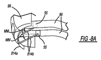
図8Aは、格納又は作動前状態の搖動可能アーム及び歩行者インタフェース814aを示す。図8A〜8Bに示す実施形態において、システム作動後、展開アーム814bは、矢印MMで示すように全体的に下方に搖動又は回転しながら、その格納位置から移動して、図8Bに示すように付属する歩行者インタフェース814aをバンパの下に配置する。
FIG. 8A shows the swingable arm and
図9Aは、システムの別の実施形態における、格納又は作動前の状態の搖動可能アーム814b及び歩行者インタフェース814aを示す。図9A〜9Bに示す特定の実施形態において、システム作動後、展開アーム814bは、矢印M’M’で示すように全体的に前方かつ下方に搖動又は回転しながら、その格納位置から移動して、図9Bに示すように、歩行者インタフェース814aをバンパの下に配置する。
FIG. 9A shows the
アーム814bは、任意の適した型の既知の回転アクチュエータ(全体的に55で示される)、例えば、ステッパモータ並びに関連するセンサ及び/又は位置エンコーダ及び他のハードウェア;ステッパモータ並びに関連するギア列、センサ、及び/又は位置エンコーダ及び他のハードウェア;既知の流体パワー回転アクチュエータ及び関連ハードウェア;又は任意の他の適した回転アクチュエータ、に動作可能に結合されてもよい。こうしたアクチュエータは、種々のベンダーから入手可能である。別個の回転アクチュエータ55がアーム814bのそれぞれに結合されてもよい、又は、両方のアームが(図7Aに示されるように)単一回転アクチュエータによって回転されてもよい。使用される回転アクチュエータの型は、歩行者保護システムがその中に配置される車両サイズエンベロープ、歩行者インタフェース814a及び回転アーム814bの特定のデザインについてのトルク要件、及び他の関連因子、のような因子に従って指定されることになる。
回転アクチュエータ(複数可)55は、コントローラ18に動作可能に結合される。コントローラから作動信号を受信すると(本明細書の他の所でも説明されるように)、回転アクチュエータ(複数可)は、歩行者インタフェース814aがその展開位置に達するまで、アーム814bを下方に及び/又は所望の弧に沿って搖動させるように動作する。所望される場合、1以上のハードストップ(図示せず)をアーム814bに動作可能に結合して、当技術分野で知られている方法でアームの回転運動を制限してもよい。
A rotary actuator (s) 55 is operably coupled to the
歩行者保護システムは、また、部材と接触した状態の歩行者によって脚係合部材に加えられる反力に応答して歩行者インタフェース814aを完全に展開した位置に維持するように構築されてもよい。アーム位置を制御するために加圧流体を使用する一実施形態において、反力は、アーム内の加圧流体によって、既知の方法で吸収されてもよい。
The pedestrian protection system may also be constructed to maintain the
搖動可能又は回転可能アーム814bを使用する一実施形態において、アームは、(例えば、テレスコピック構造を使用して)アームの長さの調整を可能にするように、又は、ハウジング又は車両上のアームの旋回位置と歩行者インタフェース814aが取り付けられるアーム814b上の位置との間の距離D9(図9Bに示す)の変動を可能にするように構築されてもよい。これは、本明細書の他の所で説明されるように、歩行者インタフェース814aの位置決めについての更なる柔軟性を提供する。
In one embodiment that uses a swingable or
ある実施形態において(例えば、図3A〜3B及び5B〜5Cに示す実施形態において)、展開機構は、歩行者インタフェースを車両の一部分に動作可能に結合する1以上のテレスコピックアームの形態である。本明細書で説明される実施形態は、2つの離間したテレスコピックアームを利用し、各アームは、歩行者インタフェースの関連部分に結合される。しかし、任意の所望の数のテレスコピックアームが使用されてもよい。同様に、アームは、特定用途の動作的、構造的、又は寸法的な要件に応じて、部材(複数可)に沿って任意の所望の1つ又は複数の位置で歩行者インタフェース(複数可)に接続されてもよい。 In certain embodiments (eg, in the embodiments shown in FIGS. 3A-3B and 5B-5C), the deployment mechanism is in the form of one or more telescopic arms that operably couple the pedestrian interface to a portion of the vehicle. The embodiments described herein utilize two spaced telescopic arms, each arm being coupled to an associated portion of the pedestrian interface. However, any desired number of telescopic arms may be used. Similarly, the arm may have pedestrian interface (s) at any desired location or locations along the member (s), depending on the application's operational, structural, or dimensional requirements. May be connected.
1以上のテレスコピックアームの形態の展開機構の例は、図3A〜3Bに示される。図3Aを参照すると、一実施形態において、アーム314bのそれぞれは、空気圧又は油圧式のピストン及びシリンダ配置の形態である。ピストンロッド314eは、ピストン314dに取り付けられて、ピストンと共に移動する。歩行者インタフェース314aの一部分は、各ピストンロッド314eの端に結合される。既知の方法で、エネルギー吸収機構が作動されると、流体流は、バルブ機構16によって、既知の方法で各シリンダ314内のピストンのいずれかの側に方向付けられ、その関連するシリンダの内部に沿うピストン314bの移動をもたらす。これは、ロッド314eの端に取り付けられた歩行者インタフェース314aの、図3Bに示す歩行者インタフェースの完全に展開した位置への、対応する移動を生じさせる。
An example of a deployment mechanism in the form of one or more telescopic arms is shown in FIGS. Referring to FIG. 3A, in one embodiment, each of the
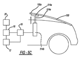
1以上のテレスコピックアームの形態の展開機構の別例は、図5B〜5Cに示される。図5Aに示すエネルギー吸収部材展開機構及びエネルギー吸収部材は、先に述べた図6A〜6Bの示す形態、又は図5B〜5Cに示す形態であってよい。図5Bを参照すると、一実施形態において、アーム514bのそれぞれは、空気圧又は油圧式のピストン及びシリンダ配置の形態である。ピストンロッド514eは、ピストン(図示せず)に取り付けられて、ピストンと共に移動する。歩行者インタフェース514aの一部分は、各ピストンロッド514eの端に結合される。既知の方法によって、エネルギー吸収機構の作動は、加圧流体のシリンダ内への導入(又は、シリンダ内への流れ)を引き起こし、その関連するシリンダの内部に沿うピストンの移動を生じさせ、それにより、ロッド514eの端に取り付けられた歩行者インタフェース514aの、図5Cに示す歩行者インタフェースの完全に展開した位置への、対応する移動を生じさせる。歩行者インタフェースの完全に展開した位置において、フード後方部分100aは、図示するように、その通常動作位置を超えるレベルに持ち上げられる。
Another example of a deployment mechanism in the form of one or more telescopic arms is shown in FIGS. The energy absorbing member deployment mechanism and the energy absorbing member shown in FIG. 5A may have the form shown in FIGS. 6A to 6B or the form shown in FIGS. 5B to 5C. Referring to FIG. 5B, in one embodiment, each of the
別の実施形態では、図6C〜6Dに関して述べたように膨張可能部材を展開機構として使用するのではなく、たった今述べたピストン及びシリンダ配置、並びにピストンロッド514eを使用して、図6C〜6Dに示すようにカウルパネル100bを歩行者係合位置に移動させる。歩行者インタフェース514aは、図6C〜6Dに示すようにカウルパネルの下側に取り付けられてもよい。エネルギー吸収機構が作動されると、ピストンロッド514eの移動は、先に述べたように図6Dに示す方法で歩行者インタフェース及びカウルパネル100bを回動させる。
In another embodiment, instead of using an inflatable member as a deployment mechanism as described with respect to FIGS. 6C-6D, the piston and cylinder arrangement just described, and the
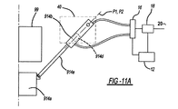
1以上のテレスコピックアームの形態の展開機構の別例は、図10〜12に示される。図11Aを参照すると、一実施形態において、アーム914bのそれぞれは、空気圧又は油圧式のピストン及びシリンダ配置の形態である。ピストンロッド914eはピストン914dに取り付けられて、ピストンと共に移動する。歩行者インタフェース914aの一部分は、各ピストンロッド914eの端に取り付けられる。既知の方法で、歩行者保護システムの作動は、加圧流体のシリンダへの導入(又は、シリンダ内への流れ)を引き起こし、その関連するシリンダの内部に沿うピストン914dの移動を生じさせる。ピストン914dの移動は、ピストンに取り付けられたロッド914eの移動を生じさせ、また同様に、ロッド914eの端に取り付けられた歩行者インタフェース914aの、歩行者インタフェースの完全に展開した位置への、対応する移動を生じさせる。
Another example of a deployment mechanism in the form of one or more telescopic arms is shown in FIGS. Referring to FIG. 11A, in one embodiment, each of the
図11Aは、ピストン及びシリンダ配置の形態の作動可能アーム914bを使用するシステムの一例を示す。アーム914b及び歩行者インタフェース914aに加えて、このシステムの実施形態は、所定の基準に従って歩行者インタフェース914aの展開を制御するためのアーム914bに結合したコントローラ18、1以上の加圧流体源、並びに、コントローラ18及びシリンダ914bに動作可能に結合し、所望されるときに加圧流体をアームに提供するように構築された(弁、ソレノイド等を含む)関連する流体流量制御機構(全体的に16で示される)を含む。
FIG. 11A shows an example of a system that uses an
アーム314b、514b、914bは、シリンダの平行な長手方向軸又はスラスト軸P1及びP2(例えば、図3A及び3Bに示す)が関連する歩行者インタフェース314a、514a、914aの最終展開位置の方に向けられる又はそれに整列するように、更には、アームのストロークが、作動されると、歩行者インタフェース314a、514a、914aを所望の完全に展開した位置に移動させるように、構築され、方向付けられ、車両に動作可能に結合されてもよい。
The
テレスコピックアームを使用するシステムに対する加圧流体源(複数可)は、例えば、空気圧システム用の圧縮機、ポンプ、及び/又は他の既知の要素の動作によってチャージされるリザーバ;空気圧若しくは他の既知の加圧ガスシステム又は油圧システム用のリザーバ、ポンプ、及び/又は他の既知の要素;又は、任意の他の適した流体源を含んでもよい。個別の加圧流体源が各シリンダに動作可能に結合されてもよい。あるいは、共通の加圧流体源が両方のシリンダに結合されてもよい。 Pressurized fluid source (s) for systems using telescopic arms can be charged, for example, by operation of compressors, pumps, and / or other known elements for pneumatic systems; pneumatic or other known It may include reservoirs, pumps, and / or other known elements for pressurized gas systems or hydraulic systems; or any other suitable fluid source. A separate pressurized fluid source may be operably coupled to each cylinder. Alternatively, a common source of pressurized fluid may be coupled to both cylinders.
他の形態のエネルギー吸収部材展開機構及びエネルギー吸収部材が同様に考えられる。歩行者との接触前に歩行者インタフェースを配置又は展開するために使用される特定の方法は、歩行者保護システムがその中に設置されてもよい利用可能なエンベロープサイズ;格納位置から展開位置までの歩行者インタフェースの距離、及び他の関連因子等の、因子によって決定されることになる。 Other forms of energy absorbing member deployment mechanisms and energy absorbing members are conceivable as well. The specific method used to place or deploy the pedestrian interface prior to contact with the pedestrian is the available envelope size in which the pedestrian protection system may be installed; from the retracted position to the deployed position Will be determined by factors such as the distance of the pedestrian interface and other related factors.
特定の実施形態において、歩行者保護システムは、ハウジング40を含み、ハウジング40には、歩行者保護システムの他のコンポーネント(例えば、歩行者インタフェース14、センサ(複数可)20、コントローラ18、任意のテレスコピックアーム及び/又は搖動型アーム、及び、任意の関連する作動機構(図示せず)、及び、任意の他の所望のコンポーネント(複数可))が搭載されて、車両フレーム又は車両の別の適した部分に固着されてもよいモジュールが形成されてもよい。ハウジングは、ハウジング上への歩行者保護システムコンポーネントの搭載、並びに、互いに対するコンポーネントの位置及び向きの固定を可能にして、歩行者保護システムの設置及びシステムの適切な動作を容易にする。ハウジングは、同様に、歩行者保護システムが既存の車両上でより容易に追加導入されることを可能にする。適したスペーサ又は搭載ブラケット(図示せず)等の搭載補助具が、同様に使用されて、ハウジングを所与の車両に取り付けるのを補助してもよい。
In certain embodiments, the pedestrian protection system includes a
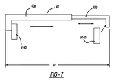
図7は、そこに他の歩行者保護システムコンポーネントを搭載するのに適したハウジング40の一実施形態の概略図である。図7に示す実施形態において、ハウジング40は、第1の部分40a、及び、第1の部分と結合すると第1の部分に対して摺動可能である、又は、その他の方法で位置的に調整可能であるように構築された第2の部分40bを含む。図示する実施形態において、第1及び第2の部分40a及び40bは、(車両に搭載されると、車両の前後軸に垂直に延在する)ハウジングの幅Wを調整可能であり、所定位置に固定されるハウジングの部分が所望の幅寸法を維持可能であるように構築される。ハウジング幅のこの調整可能な性質は、種々のサイズの車両フレームに対するハウジングの取り付けを容易にする。ハウジング部分40a及び40bが互いに対して所定位置に固定された後、歩行者保護システムの他の要素は、締結具、溶接、又は任意の他の適した1つ又は複数の方法の使用によって、ハウジング部分に取り付けられてもよい。ハウジングは、適した1つ又は複数の材料(例えば、金属材料、ポリマー等)から形成されてもよい。テレスコピックアーム914bは、図示するように、また本明細書で説明される実施形態のうちの1つの実施形態に従って、ハウジング部分に取り付けられてもよい。
FIG. 7 is a schematic diagram of one embodiment of a
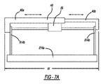
図7Aは、図7と同様の概略図であり、搖動可能又は回転可能アーム814bがハウジング40に取り付けられた一実施形態を示す。図7Aに示す実施形態では、ハウジング部分40a及び40bに回動可能に取り付けられたアーム814bが示される。アーム814bは、アーム及びハウジング40に(又は、車両に直接)動作可能に結合された単一回転アクチュエータ55によって回動される。代替的に、アーム814bのそれぞれは、個別の回転アクチュエータに動作可能に結合されてもよい。搖動可能アーム814bは、図7Aにおいてハウジングに搭載されて示されるが、ハウジング40は、また、車両に対してテレスコピックアーム(先に述べたアーム314b等)を配置し固定するために使用されてもよい。
FIG. 7A is a schematic view similar to FIG. 7, showing one embodiment with a swingable or
更に、歩行者保護システムの他の要素は、ハウジング部分40a及び40を互いに対して所定の位置に固定する前に、ハウジング部分に取り付けられてもよい。これによって、ハウジング幅Wを、特定用途の要件に応じて、他のシステム要素が既に取り付けられた状態で、特定の車両の部位への取り付けのために、調整することができる。
In addition, other elements of the pedestrian protection system may be attached to the housing portion prior to securing the
別の実施形態において、ハウジング40は、調整不可能な幅Wを有する単一の一体(unitary)構造として形成される。幅寸法Wは、フレーム又は特定の車両デザインの所定部分に対するハウジングの搭載を容易にするように定められる。
In another embodiment, the
本明細書で説明されるように、モジュールは、既存の車両コントローラ及び/又はセンサを組み入れるか又はそれに動作可能に結合されてもよく、又は、モジュールは、自己完結型であり、本明細書で説明される動作モードの1以上に従って、車両と歩行者との間の接触の前に歩行者インタフェースを作動するように構成される自身のコントローラ及び/又はセンサ(複数可)を搭載していてもよい。 As described herein, a module may incorporate or operably couple to an existing vehicle controller and / or sensor, or the module may be self-contained and described herein. Equipped with its own controller and / or sensor (s) configured to activate the pedestrian interface prior to contact between the vehicle and the pedestrian in accordance with one or more of the described modes of operation Good.
特定の実施形態において、歩行者保護システムは、歩行者保護システムの種々のコンポーネントの最終的な位置及び/又は向きが、コンポーネントが搭載される車両の部分に対して調整可能であるように構築される。例えば、先に述べたピストン−シリンダ配置のいずれも、調整可能ストロークシリンダであってよい。こうしたシリンダは、当技術分野で知られており、種々の供給業者の任意の供給業者から、例えば、イリノイ州マチェスニーパーク(Machesney Park,IL)のTRD Manufacturing,Inc.から入手可能である。 In certain embodiments, the pedestrian protection system is constructed such that the final position and / or orientation of the various components of the pedestrian protection system can be adjusted relative to the portion of the vehicle on which the component is mounted. The For example, any of the previously described piston-cylinder arrangements may be adjustable stroke cylinders. Such cylinders are known in the art and can be obtained from any of a variety of suppliers, for example, TRD Manufacturing, Inc. of Macesney Park, Ill. Is available from
また、展開可能アーム814b、914bの任意のアームが本明細書で説明されるようにハウジング40に取り付けられる場合、各シリンダの一部分は、関連するハウジング部分に回転可能に取り付けられて、特定用途の要件に応じてハウジングに対するシリンダの角度配向の調整を可能にしてもよい。シリンダは、回転可能接続部を中心に旋回して、所望の角度配向を提供し、その後、ピン、締結具、又は任意の他の適した固定機構を使用してこの配向に固定されてもよい。代替的に、車両フレームに対するシリンダの回転可能な性質は、車両フレームに対するシリンダの直接的な回転可能な取り付けによって提供されてもよい。代替的に、車両フレームに対するシリンダの回転可能な性質は、フレームに対する適したブラケットの取り付けによって提供されてもよく、シリンダは、結合されると、これに対して回転するように構築されてもよい。これは、シリンダを別個のハウジング上に搭載する必要性なしで、車両フレームに対するシリンダの配向の調整を可能にする。
Also, if any arm of the
更に、展開可能アーム814b、914bの任意のアームが本明細書で説明されるようにハウジング40に取り付けられる場合、シリンダは、テレスコピックアームの伸長軸(図3A〜3Bの軸P1又はP2)に沿うハウジングに対するシリンダの摺動可能移動ができるように、ハウジングの関連部分に搭載されてもよい。シリンダ本体は、特定用途の要件に応じてハウジングに沿って摺動可能に配置され、その後、ピン、締結具、又は任意の他の適した固定機構を使用して所与の位置に固定されてもよい。代替的に、車両フレームに対するシリンダの摺動可能な性質は、フレームに対する適したブラケット又は他のハードウェアの取り付けによって提供されてもよく、シリンダは、結合されると、これに沿って摺動するように構築されてもよい。これは、シリンダを別個のハウジング上に搭載する必要性なしで、展開軸に沿うシリンダの位置調整を可能にする。
Further, if any of the
更に、歩行者インタフェースは、任意のシリンダピストンロッド又は搖動型アームの端に(例えば、ピンを使用して)回転可能に接続されて、歩行者による荷重のかかる突出経路に対して、また、部材の最終的な展開位置に従って、歩行者インタフェースの角度配向の調整を可能にしてもよい。歩行者インタフェースは、必要に応じて配向され、任意の適した方法を使用して所望の配向で固定されてもよい。 In addition, the pedestrian interface is rotatably connected to the end of any cylinder piston rod or peristaltic arm (eg, using a pin), to a protruding path that is loaded by the pedestrian, and to the member The angular orientation of the pedestrian interface may be adjustable according to the final deployment position. The pedestrian interface may be oriented as needed and fixed in the desired orientation using any suitable method.
歩行者保護システムの他の部分は、同様に、システムの作動後に、歩行者インタフェースの完全に展開した位置が達成されることを保証しながら、車両内でのシステムの設置に関する柔軟性を提供するように、位置的に及び/又は回転による方法で、調整可能であってよい。より具体的には、説明された調整可能な性質は、車両に対するシステムコンポーネントの配置及び取付の柔軟性を提供して、歩行者インタフェースが、完全に展開すると、車両バンパに対して、また、車両の走行表面Rに対して、望ましい所定場所に存在することを保証する。 Other parts of the pedestrian protection system also provide flexibility regarding the installation of the system in the vehicle, ensuring that a fully deployed position of the pedestrian interface is achieved after system operation. As such, it may be adjustable in a positional and / or rotational manner. More specifically, the described adjustable nature provides flexibility in the placement and installation of system components relative to the vehicle so that when the pedestrian interface is fully deployed, the vehicle bumper and vehicle It is ensured that it exists at a desired predetermined position with respect to the traveling surface R of the vehicle.
特定の実施形態において、展開機構と展開機構に結合された歩行者インタフェースの両方は、歩行者インタフェースが展開位置にあるとき歩行者インタフェース接触エネルギーの少なくとも一部分を吸収するように構築される。例えば、歩行者インタフェースは、先に述べた、適した1つ又は複数のエネルギー吸収材料から形成されてもよく、一方、展開機構は、加圧流体によって作動可能であるデバイス(例えば、膨張可能エアバッグ又はブラダー)であり、歩行者−車両接触力に応答してデバイス内に収容される加圧流体の制御された排出を行うための、及び/又は、膨張可能デバイスが膨張状態に維持される間に膨張可能デバイス内のガスを排出するための圧力逃がし弁又は別の適した機構を備えてもよい。同様に、本明細書で説明されるピストン−シリンダ配置は、歩行者と歩行者インタフェースとの間の接触に応答して加圧流体を排出するための、又は、その他の方法で作動圧力の減少を可能にするための逃がし弁又は他の機構を備えてもよい。これは、機構が、歩行者−車両接触力を制御された方法で吸収するのを補助する。 In certain embodiments, both the deployment mechanism and the pedestrian interface coupled to the deployment mechanism are constructed to absorb at least a portion of the pedestrian interface contact energy when the pedestrian interface is in the deployed position. For example, the pedestrian interface may be formed from one or more suitable energy absorbing materials as described above, while the deployment mechanism is a device that can be actuated by pressurized fluid (eg, inflatable air). Bag or bladder) for controlled discharge of pressurized fluid contained in the device in response to a pedestrian-vehicle contact force and / or the inflatable device is maintained in an inflated state There may be provided a pressure relief valve or another suitable mechanism for venting the gas in the inflatable device in between. Similarly, the piston-cylinder arrangement described herein can reduce the working pressure for discharging pressurized fluid or otherwise in response to contact between the pedestrian and the pedestrian interface. A relief valve or other mechanism may be provided to enable this. This assists the mechanism in absorbing the pedestrian-vehicle contact force in a controlled manner.
展開機構でピストン−シリンダ配置を利用する特定の実施形態において、エネルギー吸収機構は、歩行者インタフェースの完全に展開された位置及び/又は向きが、歩行者インタフェースが搭載される車両の部分に対して調整可能であるように構築される。例えば、シリンダは、調整可能なストロークシリンダであってよく、それにより、歩行者インタフェースがそこまで延在してもよい格納位置からの距離の調整を可能にする。こうしたシリンダは、当技術分野で知られており、種々の供給業者のいずれかから、例えば、イリノイ州マチェスニーパークのTRD Manufacturing,Inc.から入手可能である。 In certain embodiments that utilize a piston-cylinder arrangement in the deployment mechanism, the energy absorbing mechanism is configured such that the fully deployed position and / or orientation of the pedestrian interface is relative to the portion of the vehicle on which the pedestrian interface is mounted. Built to be adjustable. For example, the cylinder may be an adjustable stroke cylinder, thereby allowing adjustment of the distance from the storage position where the pedestrian interface may extend. Such cylinders are known in the art and are available from any of a variety of suppliers, for example, TRD Manufacturing, Inc. of Machysney Park, Illinois. Is available from
望まれる場合、コントローラ18は、また、歩行者保護システムが展開に失敗したこと、システムの不具合を示し得る状態を、(コントローラに結合されたリミットセンサ又は他の適したセンサから受信した情報に応答して)車両乗員に通知するように設計された可聴の又はその他の方法で検知可能なアラーム(図示せず)に結合されてもよい。
If desired, the
本明細書で説明される原理を使用して、作動可能な展開機構及び歩行者インタフェースは、衝突時に歩行者によって接触され得る車両の任意の適した部分に組み込まれて、歩行者−車両接触力の減少及び/又は吸収を補助する、選択的に展開可能なエネルギー吸収機構を提供してもよい。 Using the principles described herein, the actuable deployment mechanism and pedestrian interface can be incorporated into any suitable portion of the vehicle that can be contacted by the pedestrian in the event of a collision to provide a pedestrian-vehicle contact force. A selectively deployable energy absorption mechanism may be provided to assist in reducing and / or absorbing.
種々の実施形態を述べるために本明細書で使用される用語「例示的な(exemplary)」は、こうした実施形態が、採り得る実施形態の、採り得る例、代表、及び/又は例証であることを示すこと意図しており、こうした用語が、こうした実施形態が必然的に特別な又は最上級の例であることを暗示することを意図していないことに留意されるべきである。 The term “exemplary” as used herein to describe various embodiments is an example, representation, and / or illustration of possible embodiments of such embodiments. It should be noted that these terms are not intended to imply that such embodiments are necessarily special or superlative examples.
本明細書で使用される用語「結合された(coupled)」、「接続された(connected)」、及び同様なものは、2つの部材を互いに直接に又は間接に結び付けること(joining)を意味する。こうした結び付けは、静的(例えば永久的)、又は、可動(例えば、取外し可能又は解除可能)であってよい。こうした結び付けは、2つの部材、若しくは、2つの部材及び任意の追加の中間部材、が互いに単一の一体型ボディとして一体形成されることによって、又は、2つの部材、若しくは、2つの部材及び任意の追加の中間部材、が互いに取り付けられることによって達成されてもよい。 As used herein, the terms “coupled”, “connected” and the like refer to joining two members directly or indirectly to each other. . Such binding may be static (eg, permanent) or movable (eg, removable or releasable). Such a connection can be made by two members, or two members and any additional intermediate members, being integrally formed with each other as a single integral body, or two members, or two members and any The additional intermediate members may be attached to each other.
本発明の実施形態の先の説明が単に例証のためのものであること、また、本明細書で開示する種々の構造的及び動作的特徴が、多数の変更を受け、その変更がいずれも、本発明の精神及び範囲から逸脱しないことが理解されるであろう。したがって、先の説明は、本発明の範囲を制限することを意味しない。むしろ、本発明の範囲は、添付の特許請求の範囲及びその等価物によってのみ決定される。 The foregoing description of the embodiments of the present invention is merely illustrative, and the various structural and operational features disclosed herein have undergone numerous changes, all of which are It will be understood that it does not depart from the spirit and scope of the invention. Accordingly, the above description is not meant to limit the scope of the invention. Rather, the scope of the present invention is determined solely by the appended claims and their equivalents.
Claims (26)
接触時に前記歩行者を衝撃緩和するように構成されるエネルギー吸収歩行者インタフェースを設けるステップと、
前記インタフェースに動作可能に結合され、格納位置と展開位置との間で前記インタフェースを移動させるように構成されるインタフェース展開機構を設けるステップと、
前記車両が移動中であるときに、かつ、前記歩行者と前記車両との間の接触前に、前記歩行者インタフェースを前記展開位置まで移動させるステップと
を含む方法。 A method for reducing the impact of a pedestrian on contact with a moving vehicle,
Providing an energy absorbing pedestrian interface configured to cushion the pedestrian upon contact;
Providing an interface deployment mechanism operatively coupled to the interface and configured to move the interface between a retracted position and a deployed position;
Moving the pedestrian interface to the deployed position when the vehicle is moving and prior to contact between the pedestrian and the vehicle.
前記インタフェースに動作可能に結合され、第1の位置と第2の位置との間で前記インタフェースを移動させるように構成されるインタフェース展開機構を設けるステップと、
前記車両が第1の所定速度以上で移動中であるとき、前記第1の位置から前記第2の位置まで前記インタフェースを移動させるステップと、を含む方法。 A method for arranging an energy absorbing pedestrian interface to receive energy from a contact between a pedestrian and a moving vehicle,
Providing an interface deployment mechanism operably coupled to the interface and configured to move the interface between a first position and a second position;
Moving the interface from the first position to the second position when the vehicle is moving at or above a first predetermined speed.
前記歩行者と車両との間の衝突事象時に歩行者を衝撃緩和するように構成されるエネルギー吸収歩行者インタフェースと、
前記インタフェースに動作可能に結合され、前記車両の速度に応答して格納位置と展開位置との間で前記インタフェースを移動させるように構成される歩行者インタフェース展開機構と、を備えるシステム。 An active pedestrian protection system,
An energy absorbing pedestrian interface configured to cushion the pedestrian during a collision event between the pedestrian and the vehicle;
A pedestrian interface deployment mechanism operatively coupled to the interface and configured to move the interface between a retracted position and a deployed position in response to the speed of the vehicle.
Applications Claiming Priority (7)
| Application Number | Priority Date | Filing Date | Title |
|---|---|---|---|
| US201361922705P | 2013-12-31 | 2013-12-31 | |
| US61/922,705 | 2013-12-31 | ||
| US14/557,385 US9365176B2 (en) | 2013-11-29 | 2014-12-01 | Active lower leg engagement system |
| US14/557,385 | 2014-12-01 | ||
| US14/588,283 | 2014-12-31 | ||
| US14/588,283 US9586555B2 (en) | 2013-12-31 | 2014-12-31 | Active pedestrian protection system |
| PCT/US2014/073087 WO2015103437A1 (en) | 2013-12-31 | 2014-12-31 | Active pedestrian protection system |
Related Child Applications (1)
| Application Number | Title | Priority Date | Filing Date |
|---|---|---|---|
| JP2019079626A Division JP6803425B2 (en) | 2013-12-31 | 2019-04-18 | Active pedestrian protection system |
Publications (2)
| Publication Number | Publication Date |
|---|---|
| JP2017518909A true JP2017518909A (en) | 2017-07-13 |
| JP2017518909A5 JP2017518909A5 (en) | 2017-08-24 |
Family
ID=53494036
Family Applications (2)
| Application Number | Title | Priority Date | Filing Date |
|---|---|---|---|
| JP2016542989A Pending JP2017518909A (en) | 2013-12-31 | 2014-12-31 | Active pedestrian protection system |
| JP2019079626A Active JP6803425B2 (en) | 2013-12-31 | 2019-04-18 | Active pedestrian protection system |
Family Applications After (1)
| Application Number | Title | Priority Date | Filing Date |
|---|---|---|---|
| JP2019079626A Active JP6803425B2 (en) | 2013-12-31 | 2019-04-18 | Active pedestrian protection system |
Country Status (4)
| Country | Link |
|---|---|
| US (2) | US9586555B2 (en) |
| JP (2) | JP2017518909A (en) |
| DE (1) | DE112014006087T5 (en) |
| WO (1) | WO2015103437A1 (en) |
Families Citing this family (13)
| Publication number | Priority date | Publication date | Assignee | Title |
|---|---|---|---|---|
| WO2015103333A1 (en) | 2013-12-30 | 2015-07-09 | Tk Holdings Inc. | Active knee protection system |
| GB2539975B (en) * | 2015-09-24 | 2017-05-17 | Ford Global Tech Llc | Deployable pedestrian safety device for vehicles |
| US9586552B1 (en) * | 2015-10-29 | 2017-03-07 | Ford Global Technologies, Llc | Vehicle seat back including a deployable device |
| US9821754B2 (en) * | 2016-02-26 | 2017-11-21 | Ford Global Technologies, Llc | Spring assist lock and release lower leg front-end stiffener |
| JP6683394B2 (en) * | 2016-03-31 | 2020-04-22 | 株式会社Subaru | Vehicle cyclist protection equipment |
| US10246036B2 (en) | 2017-06-30 | 2019-04-02 | Ford Global Technologies, Llc | Secondary bumper assembly |
| CN107690399A (en) * | 2017-08-17 | 2018-02-13 | 驭势科技(北京)有限公司 | A kind of pedestrains safety guard method and equipment for vehicle |
| JP6909440B2 (en) | 2017-09-19 | 2021-07-28 | いすゞ自動車株式会社 | Vehicle pedestrian protection device |
| CN108973908B (en) * | 2018-06-17 | 2020-04-07 | 廊坊翔宇塑料制品有限公司 | Automobile front bumper with sinking type buffering function |
| US11203318B2 (en) | 2018-06-18 | 2021-12-21 | Waymo Llc | Airbag extension system |
| DE102020124824A1 (en) | 2020-09-23 | 2022-03-24 | Autoliv Development Ab | PEDESTRIAN PROTECTION DEVICE |
| CN113335209B (en) * | 2021-06-25 | 2022-09-06 | 中国人民解放军63653部队 | A protection armor and police vehicle for police vehicle |
| US11827168B2 (en) | 2022-02-07 | 2023-11-28 | Ford Global Technologies, Llc | Downwardly-deployable bumper extension |
Citations (8)
| Publication number | Priority date | Publication date | Assignee | Title |
|---|---|---|---|---|
| US6394512B1 (en) * | 2000-12-15 | 2002-05-28 | Ford Global Technologies, Inc. | Vehicle bumper system |
| US6415883B1 (en) * | 2002-01-24 | 2002-07-09 | Ford Global Technologies, Inc. | Deployable A-pillar covers for pedestrian protection |
| JP2002544059A (en) * | 1999-05-17 | 2002-12-24 | エドシャ・アクチェンゲゼルシャフト | Front bonnet structure |
| JP2004074971A (en) * | 2002-08-21 | 2004-03-11 | Honda Motor Co Ltd | Collision object protecting device for vehicle |
| JP2005132219A (en) * | 2003-10-30 | 2005-05-26 | Hino Motors Ltd | Entanglement prevention device |
| JP2005132258A (en) * | 2003-10-31 | 2005-05-26 | Toyota Motor Corp | Front structure for car body |
| JP2006298150A (en) * | 2005-04-20 | 2006-11-02 | Toyota Motor Corp | Airbag device |
| WO2013117552A1 (en) * | 2012-02-06 | 2013-08-15 | Jaguar Land Rover Limited | Active hood or bonnet system for a vehicle |
Family Cites Families (62)
| Publication number | Priority date | Publication date | Assignee | Title |
|---|---|---|---|---|
| US3236552A (en) | 1963-05-20 | 1966-02-22 | Superior Coach Corp | Pedestrian guard |
| US3525535A (en) | 1967-02-18 | 1970-08-25 | Gic Kk | Safety device for vehicle passengers |
| US3656791A (en) | 1970-10-12 | 1972-04-18 | William H Nienstedt | Vehicle impact-cushioning device |
| US3779325A (en) | 1972-04-07 | 1973-12-18 | Valmet Oy | Motor guard |
| US4176858A (en) | 1974-01-04 | 1979-12-04 | Safety Consultants | Energy absorbing bumper system |
| US5106137A (en) | 1991-06-28 | 1992-04-21 | Davidson Textron Inc. | Vehicle bumper with combination foam and air bag energy absorber |
| JP2888116B2 (en) * | 1993-10-15 | 1999-05-10 | トヨタ自動車株式会社 | Pillar airbag device |
| DE19501859A1 (en) | 1995-01-23 | 1996-07-25 | Volkswagen Ag | Safety arrangement for a motor vehicle |
| US5810427A (en) | 1996-03-18 | 1998-09-22 | Hartmann; Albrecht | Motor vehicle |
| US6106038A (en) | 1996-09-07 | 2000-08-22 | Dreher; Peter A. | System for collision damage reduction |
| US5725265A (en) | 1997-01-16 | 1998-03-10 | Baber; Jeff | Air bag system for vehicle bumpers |
| DE19803165A1 (en) * | 1998-01-28 | 1999-07-29 | Bayerische Motoren Werke Ag | Safety unit for motor vehicle to reduce risk of injury to pedestrian by impact against windscreen frame |
| WO2000002751A1 (en) | 1998-07-09 | 2000-01-20 | Giat Industries | Bumper equipped with shock absorbing means |
| US6089628A (en) * | 1998-09-02 | 2000-07-18 | Ford Global Technologies, Inc. | Stiffener assembly for bumper system of motor vehicles |
| DE19918202A1 (en) | 1999-04-22 | 2000-10-26 | Bayer Ag | Safety bumper for automobile comprises energy absorbing elements activated by impact sensor to produce uninterrupted contour with front of main bumper structure |
| US6293362B1 (en) * | 1999-07-09 | 2001-09-25 | Honda Giken Kogyo Kabushiki Kaisha | Vehicle hood apparatus |
| SE9902839D0 (en) * | 1999-08-05 | 1999-08-05 | Evert Palmquist | Vehicle collision protection |
| US20010030431A1 (en) | 1999-12-10 | 2001-10-18 | Killday Timothy G. | Safety compliant rear underride bumper |
| DE10018893A1 (en) | 2000-04-14 | 2001-10-25 | Acts Gmbh & Co Kg | Instrument panel for a motor vehicle and method for producing a plastic carrier for an instrument panel |
| JP3711847B2 (en) * | 2000-07-27 | 2005-11-02 | 日産自動車株式会社 | Airbag device for vehicle |
| US6923483B2 (en) | 2001-01-11 | 2005-08-02 | Universal Propulsion Company, Inc. | Bumper airbag and system |
| SE522817C2 (en) | 2001-12-21 | 2004-03-09 | Volvo Lastvagnar Ab | Method of moving underrun protection and arrangements for underrun protection for vehicles |
| GB0201199D0 (en) * | 2002-01-19 | 2002-03-06 | Ford Global Tech Inc | A motor vehicle and a bumper assembly therefor |
| JP4075414B2 (en) * | 2002-03-07 | 2008-04-16 | 株式会社デンソー | Vehicle front bumper device |
| US6701569B1 (en) | 2002-04-30 | 2004-03-09 | Valeo Electrical Systems, Inc. | Wiper pivot housing with frangible mount |
| JP2004058726A (en) | 2002-07-25 | 2004-02-26 | Fuji Heavy Ind Ltd | Bumper structure for automobile |
| GB2397559A (en) * | 2003-01-22 | 2004-07-28 | Autoliv Dev | Airbag arrangement for windscreen and A-pillar |
| US6726260B1 (en) | 2003-02-20 | 2004-04-27 | General Motors Corporation | Extending bumper with combined stiffener and method |
| US6834899B2 (en) | 2003-03-24 | 2004-12-28 | Autoliv Asp, Inc. | Bumper assembly that provides early crash detection |
| JP4206804B2 (en) * | 2003-04-15 | 2009-01-14 | トヨタ自動車株式会社 | Body protection device |
| JP2004338557A (en) * | 2003-05-15 | 2004-12-02 | Mazda Motor Corp | Airbag device |
| DE10332702A1 (en) | 2003-07-18 | 2005-02-10 | Robert Bosch Gmbh | Pedestrian protection device |
| EP1607283B1 (en) * | 2004-06-18 | 2007-08-01 | Ford Global Technologies, LLC | Device for reducing the impact for pedestrians |
| FR2872477B1 (en) | 2004-07-05 | 2007-10-12 | Faurecia Bloc Avant | FRONT BLOCK FOR MOTOR VEHICLE COMPRISING A MOBILE REGION |
| JP4376743B2 (en) | 2004-09-21 | 2009-12-02 | タカタ株式会社 | Collision detection device, protection device |
| WO2006070865A1 (en) | 2004-12-28 | 2006-07-06 | Kabushiki Kaisha Toyota Chuo Kenkyusho | Vehicle motion control device |
| US20070125589A1 (en) * | 2005-12-06 | 2007-06-07 | Murphy Morgan D | Situationally dependent vehicle structure for pedestrian protection |
| US20070138815A1 (en) | 2005-12-21 | 2007-06-21 | Kojima Press Industry Co., Ltd. | Pedestrian protection apparatus for vehicle |
| EP1986895B1 (en) | 2006-02-24 | 2015-11-04 | Autoliv Development AB | Bumper air bag |
| US8141918B2 (en) | 2006-02-24 | 2012-03-27 | Honda Motor Co., Ltd. | Pedestrian bumper system and method |
| JP4317203B2 (en) | 2006-06-13 | 2009-08-19 | 小島プレス工業株式会社 | Pedestrian protection device for vehicles |
| US7441828B2 (en) | 2006-06-14 | 2008-10-28 | Kojima Press Industry Co., Ltd. | Pedestrian protection apparatus for vehicle |
| US7703819B2 (en) | 2006-06-21 | 2010-04-27 | Concept Mouldings Ltd. | Pedestrian protection |
| WO2008007090A1 (en) * | 2006-07-14 | 2008-01-17 | Concept Mouldings Ltd | Safety system |
| US7413049B2 (en) * | 2006-10-18 | 2008-08-19 | Antolin Asp, Inc. | Pedestrian protection hood lifting systems |
| JP2009138875A (en) * | 2007-12-07 | 2009-06-25 | Toyoda Gosei Co Ltd | Actuator |
| US7909373B2 (en) | 2007-12-14 | 2011-03-22 | Paul Donovan | Extendable bumper |
| JP4867944B2 (en) | 2008-03-27 | 2012-02-01 | 豊田合成株式会社 | Pedestrian protection device |
| US7757804B1 (en) | 2008-05-05 | 2010-07-20 | Li Phillip S | Pedestrian vehicle collision safety system |
| US20100156080A1 (en) | 2008-12-23 | 2010-06-24 | Napier Kenneth L | Vehicle capture and restraint device |
| US7997375B2 (en) * | 2009-04-17 | 2011-08-16 | Tony Shaw | Vehicle hood apparatus |
| KR101219708B1 (en) | 2011-06-17 | 2013-01-21 | 기아자동차주식회사 | External air-bag for a vehicle |
| EP2594438A1 (en) | 2011-11-16 | 2013-05-22 | Volvo Car Corporation | Inflatable device and deployable vehicle front surface with inflatable device |
| US9834171B2 (en) * | 2013-05-08 | 2017-12-05 | GM Global Technology Operations LLC | Fender located pedestrian protection airbag |
| CN103434476B (en) | 2013-08-09 | 2016-04-27 | 浙江吉利汽车研究院有限公司 | A kind of automotive safety system |
| US8950800B1 (en) * | 2013-11-11 | 2015-02-10 | Ford Global Technologies, Llc | Deployable lower leg stiffener for pedestrian protection |
| US9033092B1 (en) * | 2013-11-21 | 2015-05-19 | Ford Global Technologies, Llc | Vehicle front end structure providing pedestrian protection |
| WO2015081344A2 (en) * | 2013-11-29 | 2015-06-04 | Tk Holdings Inc. | Active lower leg engagement system |
| WO2015103333A1 (en) * | 2013-12-30 | 2015-07-09 | Tk Holdings Inc. | Active knee protection system |
| JP5949803B2 (en) * | 2014-02-07 | 2016-07-13 | トヨタ自動車株式会社 | Collision detection device |
| US9102290B1 (en) | 2014-02-13 | 2015-08-11 | Ford Global Technologies, Llc | Vehicle steering and braking deployment logic for pedestrian protection leg stiffener |
| DE102014010872A1 (en) * | 2014-07-24 | 2016-01-28 | Daimler Ag | Vehicle with a pedestrian protection device |
-
2014
- 2014-12-31 WO PCT/US2014/073087 patent/WO2015103437A1/en active Application Filing
- 2014-12-31 US US14/588,283 patent/US9586555B2/en active Active
- 2014-12-31 DE DE112014006087.9T patent/DE112014006087T5/en not_active Withdrawn
- 2014-12-31 JP JP2016542989A patent/JP2017518909A/en active Pending
-
2017
- 2017-03-06 US US15/450,498 patent/US10421428B2/en active Active
-
2019
- 2019-04-18 JP JP2019079626A patent/JP6803425B2/en active Active
Patent Citations (8)
| Publication number | Priority date | Publication date | Assignee | Title |
|---|---|---|---|---|
| JP2002544059A (en) * | 1999-05-17 | 2002-12-24 | エドシャ・アクチェンゲゼルシャフト | Front bonnet structure |
| US6394512B1 (en) * | 2000-12-15 | 2002-05-28 | Ford Global Technologies, Inc. | Vehicle bumper system |
| US6415883B1 (en) * | 2002-01-24 | 2002-07-09 | Ford Global Technologies, Inc. | Deployable A-pillar covers for pedestrian protection |
| JP2004074971A (en) * | 2002-08-21 | 2004-03-11 | Honda Motor Co Ltd | Collision object protecting device for vehicle |
| JP2005132219A (en) * | 2003-10-30 | 2005-05-26 | Hino Motors Ltd | Entanglement prevention device |
| JP2005132258A (en) * | 2003-10-31 | 2005-05-26 | Toyota Motor Corp | Front structure for car body |
| JP2006298150A (en) * | 2005-04-20 | 2006-11-02 | Toyota Motor Corp | Airbag device |
| WO2013117552A1 (en) * | 2012-02-06 | 2013-08-15 | Jaguar Land Rover Limited | Active hood or bonnet system for a vehicle |
Also Published As
| Publication number | Publication date |
|---|---|
| US10421428B2 (en) | 2019-09-24 |
| JP6803425B2 (en) | 2020-12-23 |
| DE112014006087T5 (en) | 2016-12-01 |
| US9586555B2 (en) | 2017-03-07 |
| WO2015103437A1 (en) | 2015-07-09 |
| US20150203067A1 (en) | 2015-07-23 |
| US20170182971A1 (en) | 2017-06-29 |
| JP2019142498A (en) | 2019-08-29 |
Similar Documents
| Publication | Publication Date | Title |
|---|---|---|
| JP6803425B2 (en) | Active pedestrian protection system | |
| JP6599872B2 (en) | Active knee protection system | |
| JP6529499B2 (en) | Active leg restraint system | |
| JP5030968B2 (en) | Crew restraint device for automobile | |
| US6056336A (en) | Air bag with internal shock absorber | |
| US7798521B2 (en) | Lower limb protecting airbag apparatus | |
| US9527466B2 (en) | Offset impact countermeasures | |
| WO2016164138A1 (en) | Airbag assemblies for vehicles with generous leg room | |
| JP2009520627A5 (en) | ||
| US20120049497A1 (en) | Inflatable knee airbag assemblies with articulating housings | |
| US11691581B1 (en) | Extendable bumpers for vehicles | |
| JP2008546595A (en) | Automobile with under-protection device | |
| CN105793120B (en) | Active shank mating system | |
| WO2016194341A1 (en) | Arrangement structure of occupant protection device | |
| CN105873801A (en) | Active pedestrian protection system | |
| KR100878629B1 (en) | Tilting device of steering column for working together airbag system | |
| KR910006988Y1 (en) | Bumping seat | |
| JP2022011206A (en) | Occupant lower limb restraining device |
Legal Events
| Date | Code | Title | Description |
|---|---|---|---|
| RD02 | Notification of acceptance of power of attorney |
Free format text: JAPANESE INTERMEDIATE CODE: A7422 Effective date: 20161014 |
|
| RD04 | Notification of resignation of power of attorney |
Free format text: JAPANESE INTERMEDIATE CODE: A7424 Effective date: 20161025 |
|
| A521 | Request for written amendment filed |
Free format text: JAPANESE INTERMEDIATE CODE: A523 Effective date: 20170609 |
|
| A621 | Written request for application examination |
Free format text: JAPANESE INTERMEDIATE CODE: A621 Effective date: 20170609 |
|
| A977 | Report on retrieval |
Free format text: JAPANESE INTERMEDIATE CODE: A971007 Effective date: 20180405 |
|
| A131 | Notification of reasons for refusal |
Free format text: JAPANESE INTERMEDIATE CODE: A131 Effective date: 20180417 |
|
| A601 | Written request for extension of time |
Free format text: JAPANESE INTERMEDIATE CODE: A601 Effective date: 20180717 |
|
| A521 | Request for written amendment filed |
Free format text: JAPANESE INTERMEDIATE CODE: A523 Effective date: 20180914 |
|
| A02 | Decision of refusal |
Free format text: JAPANESE INTERMEDIATE CODE: A02 Effective date: 20181218 |
|
| A711 | Notification of change in applicant |
Free format text: JAPANESE INTERMEDIATE CODE: A711 Effective date: 20190207 |
|
| A521 | Request for written amendment filed |
Free format text: JAPANESE INTERMEDIATE CODE: A523 Effective date: 20190418 |
|
| C60 | Trial request (containing other claim documents, opposition documents) |
Free format text: JAPANESE INTERMEDIATE CODE: C60 Effective date: 20190418 |
|
| A911 | Transfer to examiner for re-examination before appeal (zenchi) |
Free format text: JAPANESE INTERMEDIATE CODE: A911 Effective date: 20190426 |
|
| C21 | Notice of transfer of a case for reconsideration by examiners before appeal proceedings |
Free format text: JAPANESE INTERMEDIATE CODE: C21 Effective date: 20190507 |
|
| A912 | Re-examination (zenchi) completed and case transferred to appeal board |
Free format text: JAPANESE INTERMEDIATE CODE: A912 Effective date: 20190531 |
|
| C211 | Notice of termination of reconsideration by examiners before appeal proceedings |
Free format text: JAPANESE INTERMEDIATE CODE: C211 Effective date: 20190604 |
|
| C22 | Notice of designation (change) of administrative judge |
Free format text: JAPANESE INTERMEDIATE CODE: C22 Effective date: 20191029 |
|
| C22 | Notice of designation (change) of administrative judge |
Free format text: JAPANESE INTERMEDIATE CODE: C22 Effective date: 20191210 |
|
| C13 | Notice of reasons for refusal |
Free format text: JAPANESE INTERMEDIATE CODE: C13 Effective date: 20200218 |
|
| C19 | Decision taken to dismiss amendment |
Free format text: JAPANESE INTERMEDIATE CODE: C19 Effective date: 20200310 |
|
| C30A | Notification sent |
Free format text: JAPANESE INTERMEDIATE CODE: C3012 Effective date: 20200310 |
|
| C22 | Notice of designation (change) of administrative judge |
Free format text: JAPANESE INTERMEDIATE CODE: C22 Effective date: 20200623 |
|
| C23 | Notice of termination of proceedings |
Free format text: JAPANESE INTERMEDIATE CODE: C23 Effective date: 20200630 |
|
| C03 | Trial/appeal decision taken |
Free format text: JAPANESE INTERMEDIATE CODE: C03 Effective date: 20200825 |
|
| C30A | Notification sent |
Free format text: JAPANESE INTERMEDIATE CODE: C3012 Effective date: 20200825 |