JP2017191385A - Instrument maintenance device, instrument maintenance method, instrument maintenance program, and recording medium - Google Patents
Instrument maintenance device, instrument maintenance method, instrument maintenance program, and recording medium Download PDFInfo
- Publication number
- JP2017191385A JP2017191385A JP2016079151A JP2016079151A JP2017191385A JP 2017191385 A JP2017191385 A JP 2017191385A JP 2016079151 A JP2016079151 A JP 2016079151A JP 2016079151 A JP2016079151 A JP 2016079151A JP 2017191385 A JP2017191385 A JP 2017191385A
- Authority
- JP
- Japan
- Prior art keywords
- maintenance
- information
- item
- display
- unit
- Prior art date
- Legal status (The legal status is an assumption and is not a legal conclusion. Google has not performed a legal analysis and makes no representation as to the accuracy of the status listed.)
- Pending
Links
Images

Classifications
-
- G—PHYSICS
- G06—COMPUTING; CALCULATING OR COUNTING
- G06Q—INFORMATION AND COMMUNICATION TECHNOLOGY [ICT] SPECIALLY ADAPTED FOR ADMINISTRATIVE, COMMERCIAL, FINANCIAL, MANAGERIAL OR SUPERVISORY PURPOSES; SYSTEMS OR METHODS SPECIALLY ADAPTED FOR ADMINISTRATIVE, COMMERCIAL, FINANCIAL, MANAGERIAL OR SUPERVISORY PURPOSES, NOT OTHERWISE PROVIDED FOR
- G06Q10/00—Administration; Management
- G06Q10/20—Administration of product repair or maintenance
-
- G—PHYSICS
- G05—CONTROLLING; REGULATING
- G05B—CONTROL OR REGULATING SYSTEMS IN GENERAL; FUNCTIONAL ELEMENTS OF SUCH SYSTEMS; MONITORING OR TESTING ARRANGEMENTS FOR SUCH SYSTEMS OR ELEMENTS
- G05B19/00—Programme-control systems
- G05B19/02—Programme-control systems electric
- G05B19/04—Programme control other than numerical control, i.e. in sequence controllers or logic controllers
- G05B19/042—Programme control other than numerical control, i.e. in sequence controllers or logic controllers using digital processors
- G05B19/0423—Input/output
-
- G—PHYSICS
- G05—CONTROLLING; REGULATING
- G05B—CONTROL OR REGULATING SYSTEMS IN GENERAL; FUNCTIONAL ELEMENTS OF SUCH SYSTEMS; MONITORING OR TESTING ARRANGEMENTS FOR SUCH SYSTEMS OR ELEMENTS
- G05B15/00—Systems controlled by a computer
- G05B15/02—Systems controlled by a computer electric
-
- G—PHYSICS
- G05—CONTROLLING; REGULATING
- G05B—CONTROL OR REGULATING SYSTEMS IN GENERAL; FUNCTIONAL ELEMENTS OF SUCH SYSTEMS; MONITORING OR TESTING ARRANGEMENTS FOR SUCH SYSTEMS OR ELEMENTS
- G05B2219/00—Program-control systems
- G05B2219/20—Pc systems
- G05B2219/25—Pc structure of the system
- G05B2219/25257—Microcontroller
Abstract
Description
本発明は、機器保全装置、機器保全方法、機器保全プログラム及び記録媒体に関する。 The present invention relates to a device maintenance apparatus, a device maintenance method, a device maintenance program, and a recording medium.
従来から、化学等の工業プラント、ガス田や油田等の井戸元やその周辺を管理制御するプラント、水力・火力・原子力等の発電を管理制御するプラント、太陽光や風力等の環境発電を管理制御するプラント、上下水やダム等を管理制御するプラント等のプラントや工場等(以下、これらを総称する場合には「プラント」という)においては、フィールド機器と呼ばれる測定器又は操作器等の現場機器と、これらを制御する制御装置とが通信手段を介して接続された分散制御システム(DCS:Distributed Control System)が構築されており、高度な自動操業が実現されている。このような分散制御システムが構築されたプラントにおいては、異常な動作の予防、測定精度の維持等の観点から、作業者によるフィールド機器(以下、「機器」と略す場合がある。)の保全が定期又は不定期に行われる。 Conventionally, chemical and industrial plants, plants that manage and control wells such as gas fields and oil fields, and their surroundings, plants that manage and control power generation such as hydropower, thermal power, and nuclear power, and environmental power generation such as solar and wind power In a plant to be controlled, a plant or factory such as a plant to manage and control water and sewage, a dam, etc. (hereinafter referred to as “plant” when collectively referred to as these), a field device called a measuring instrument or an operating device A distributed control system (DCS: Distributed Control System) in which devices and control devices that control these devices are connected via communication means is constructed, and high-level automatic operation is realized. In a plant in which such a distributed control system is constructed, maintenance of field devices (hereinafter may be abbreviated as “device”) by an operator is performed from the viewpoint of preventing abnormal operation and maintaining measurement accuracy. Performed regularly or irregularly.
フィールド機器の保全は、フィールド機器との間で有線通信又は無線通信が可能な機器保全装置を用いて行われる。この機器保全装置は、例えばフィールド機器の保全を行うための専用のプログラムがインストールされた、ノート型又はタブレット型のコンピュータ、PDA(Personal Digital Assistant)、又はスマートフォン等である。フィールド機器の保全項目には、例えば、保全対象のフィールド機器に設定等されている機器情報を読み出して確認する確認作業、新たな機器情報を保全対象のフィールド機器に設定する設定作業等、保全対象のフィールド機器に応じた様々な保全作業が含まれる。 Maintenance of the field device is performed using a device maintenance device capable of wired communication or wireless communication with the field device. This device maintenance apparatus is, for example, a notebook or tablet computer, a PDA (Personal Digital Assistant), a smartphone, or the like in which a dedicated program for maintaining field devices is installed. Field device maintenance items include, for example, confirmation work for reading and confirming device information set in the field device to be maintained, setting work for setting new device information in the field device to be maintained, etc. Various maintenance work according to the field equipment is included.
機器保全装置は、有線通信又は無線通信を介してフィールド機器と接続して、接続されたフィールド機器の一覧を表示画面に表示する(例えば、特許文献1を参照)。保全を行う作業者は、表示されたフィールド機器の一覧の中から1つのフィールド機器を選択する画面、選択したフィールド機器における保全項目のカテゴリを選択する画面、選択したカテゴリの中からの保全項目を選択する画面、選択した保全項目を設定する画面、設定した保全項目を実行させるための画面、実施した保全項目の結果を入力するための画面、保全項目の実行結果を出力するための画面等、機器保全装置の表示画面を適宜切り替えて保全項目に係る保全作業を行う。 The device maintenance apparatus is connected to a field device via wired communication or wireless communication, and displays a list of connected field devices on a display screen (see, for example, Patent Document 1). The maintenance worker selects a field device from the displayed list of field devices, selects a maintenance item category for the selected field device, and selects a maintenance item from the selected category. A screen to select, a screen to set the selected maintenance item, a screen to execute the set maintenance item, a screen to input the result of the executed maintenance item, a screen to output the execution result of the maintenance item, etc. Maintenance work related to the maintenance items is performed by switching the display screen of the equipment maintenance device as appropriate.
しかし、プラント内に保全対象のフィールド機器が大量に存在すると、保全対象のフィールド機器毎に機器保全装置の表示画面を切り替えて保全項目を実行させる必要があり、機器保全装置の表示画面を遷移させる操作が増えて保全作業の作業効率が低下する場合があった。 However, if there are a large number of field devices to be maintained in the plant, it is necessary to switch the display screen of the device maintenance device for each field device to be maintained to execute the maintenance item, and the display screen of the device maintenance device is changed. In some cases, the number of operations increases and the efficiency of maintenance work decreases.
また、保全対象のフィールド機器が1台であったとしても、保全項目の設定、保全項目の実行、実行した保全項目の進行状況の把握、保全項目の結果入力、保全項目の結果の出力等において、機器保全装置の表示画面を遷移させる操作が生じ保全作業の作業効率が低下する場合があった。 Even if there is only one field device to be maintained, maintenance item setting, maintenance item execution, grasping the progress of the executed maintenance item, maintenance item result input, maintenance item result output, etc. In some cases, an operation for changing the display screen of the equipment maintenance device occurs, and the work efficiency of the maintenance work is lowered.
本発明は上記事情に鑑みてなされたものであり、保全作業の作業効率の向上を図ることができる、機器保全装置、機器保全方法、機器保全プログラム及び記録媒体を提供することを目的とする。 The present invention has been made in view of the above circumstances, and an object thereof is to provide an apparatus maintenance apparatus, an apparatus maintenance method, an apparatus maintenance program, and a recording medium that can improve the efficiency of maintenance work.
上記の課題を解決するため、本発明の機器保全装置は、機器の情報と、前記機器の保全項目とを、対応付けて保管する機器情報保管部と、前記機器の情報を取得する取得部と、取得された前記機器の情報に対応付けて保管された前記保全項目の中の少なくとも一つの所定の保全項目を前記機器に対して実行させるための操作部を、取得された前記機器の情報とともに表示する表示部とを備える。 In order to solve the above problems, the device maintenance apparatus of the present invention includes a device information storage unit that stores device information and the maintenance items of the device in association with each other, and an acquisition unit that acquires the device information. The operation unit for causing the device to execute at least one predetermined maintenance item among the maintenance items stored in association with the acquired information of the device, together with the acquired information of the device A display unit for displaying.
また、本発明の機器保全装置において、表示された前記操作部の操作に応じて、操作された前記操作部に対応した保全項目を実行させる保全実行部と、実行させた前記保全項目の結果を保存する保全情報保存部とをさらに備える。 Further, in the device maintenance apparatus of the present invention, the maintenance execution unit that executes the maintenance item corresponding to the operated operation unit according to the operation of the displayed operation unit, and the result of the executed maintenance item A maintenance information storage unit for storing the information;
また、本発明の機器保全装置において、前記表示部は、前記操作部の操作に応して実行される保全項目の進行状況を表示する。 In the device maintenance apparatus of the present invention, the display unit displays a progress status of maintenance items executed in response to an operation of the operation unit.
また、本発明の機器保全装置において、前記表示部は、保存された前記結果に基づく表示を、取得された前記機器の情報とともに表示する。 Moreover, the apparatus maintenance apparatus of this invention WHEREIN: The said display part displays the display based on the said stored result with the information of the acquired said apparatus.
また、本発明の機器保全装置において、前記表示部は、保存された前記結果に基づく報告書を出力するための報告書出力操作部を、取得された前記機器の情報とともにさらに表示する。 In the device maintenance apparatus of the present invention, the display unit further displays a report output operation unit for outputting a report based on the stored result together with the acquired information on the device.
また、本発明の機器保全装置において、取得された前記機器の情報に基づき、前記所定の保全項目を特定する保全項目特定部を、さらに備える。 The device maintenance apparatus of the present invention further includes a maintenance item specifying unit that specifies the predetermined maintenance item based on the acquired information on the device.
また、本発明の機器保全装置において、前記保全項目特定部は、保存された前記結果に基づき、前記所定の保全項目を特定する。 In the device maintenance apparatus of the present invention, the maintenance item specifying unit specifies the predetermined maintenance item based on the stored result.
また、本発明の機器保全装置において、前記取得部は、前記機器と通信可能に接続し、接続した前記機器の情報を取得する。 In the device maintenance apparatus of the present invention, the acquisition unit is connected to the device so as to be communicable, and acquires information on the connected device.
上記の課題を解決するため、本発明の機器保全装方法は、機器の情報と、前記機器の保全項目とを、対応付けて保管する機器情報保管ステップと、前記機器の情報を取得する取得ステップと、取得された前記機器の情報に対応付けて保管された前記保全項目の中の少なくとも一つの所定の保全項目を前記機器に対して実行させるための操作部を、取得された前記機器の情報とともに表示する表示ステップとを含む。 In order to solve the above problems, the device maintenance method of the present invention includes a device information storage step for storing device information and the maintenance items of the device in association with each other, and an acquisition step for acquiring the device information. And information on the acquired device, an operation unit for causing the device to execute at least one predetermined maintenance item among the maintenance items stored in association with the acquired information on the device. And a display step for displaying together.
上記の課題を解決するため、本発明の機器保全装プログラムは、機器の情報と、前記機器の保全項目とを、対応付けて保管する機器情報保管処理と、前記機器の情報を取得する取得処理と、取得された前記機器の情報に対応付けて保管された前記保全項目の中の少なくとも一つの所定の保全項目を前記機器に対して実行させるための操作部を、取得された前記機器の情報とともに表示する表示処理とをコンピュータに実行させる。 In order to solve the above problems, the device maintenance program of the present invention includes a device information storage process for storing device information and the maintenance items of the device in association with each other, and an acquisition process for acquiring the device information. And information on the acquired device, an operation unit for causing the device to execute at least one predetermined maintenance item among the maintenance items stored in association with the acquired information on the device. And causing the computer to execute display processing to be displayed together.
上記の課題を解決するため、本発明の記録媒体は、機器の情報と、前記機器の保全項目とを、対応付けて保管する機器情報保管処理と、前記機器の情報を取得する取得処理と、取得された前記機器の情報に対応付けて保管された前記保全項目の中の少なくとも一つの所定の保全項目を前記機器に対して実行させるための操作部を、取得された前記機器の情報とともに表示する表示処理とをコンピュータに実行させるための機器保全プログラムを記録する。 In order to solve the above-described problems, the recording medium of the present invention includes device information storage processing for storing device information and the maintenance items of the device in association with each other, acquisition processing for acquiring the device information, An operation unit for causing the device to execute at least one predetermined maintenance item among the maintenance items stored in association with the acquired device information is displayed together with the acquired device information. A device maintenance program for causing the computer to execute display processing to be recorded is recorded.
本発明によれば、保全作業の作業効率の向上を図ることができる、機器保全装置、機器保全方法、機器保全プログラム及び記録媒体を提供することができる。 According to the present invention, it is possible to provide a device maintenance device, a device maintenance method, a device maintenance program, and a recording medium that can improve the efficiency of maintenance work.
以下、図面を参照して本発明の一実施形態における機器保全装置、機器保全方法、機器保全プログラム及び記録媒体について詳細に説明する。 Hereinafter, a device maintenance apparatus, a device maintenance method, a device maintenance program, and a recording medium according to an embodiment of the present invention will be described in detail with reference to the drawings.
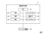
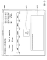
先ず、図1を用いて、機器保全装置のハードウェア構成を説明する。図1は、実施形態における機器保全装置1のハードウェア構成の一例を示すブロック図である。
First, the hardware configuration of the device maintenance apparatus will be described with reference to FIG. FIG. 1 is a block diagram illustrating an example of a hardware configuration of the
図1において、機器保全装置1は、CPU(Central Processing Unit)11、RAM(Random Access Memory)12、ROM(Read Only Memory)13、HDD(Hard Disk Drive)14、タッチパネル15、通信I/F(Interface)16、及びカードスロット17を有する。機器保全装置1は、フィールド機器19と通信可能に接続される。
In FIG. 1, a
機器保全装置1は、ノート型PC、タブレット型PC、PDA、又はスマートフォン等の汎用装置、又は機器保全専用の装置である。機器保全装置1は、フィールド機器の保全を行うための機器保全プログラムを含み、機器保全プログラムが実行されることによってフィールド機器の保全作業を支援する。機器保全装置1は、保全作業を実施する作業者によってプラント内で可搬され、作業者によって操作される。
The
CPU11は、RAM12、ROM13又はHDD14に記憶されたプログラムを実行することにより、機器保全装置1の制御を行う。機器保全プログラムは、例えば、機器保全プログラムを記録した記録媒体、又はネットワークを介した機器保全プログラムを提供するサーバ等から取得されて、HDD14にインストールされ、RAM12にCPU11から読出し可能に記憶される。
The
タッチパネル15は、操作入力機能と表示機能とを有する操作表示機能を有する。タッチパネル15は、フィールド機器の保全に係る保全情報と、保全対象の機器に対する保全項目を含む作業対象をリストにした保全リストを表示する。また、タッチパネル15は、作業者に対して指先又はタッチペン等を用いた操作入力を可能にする。本実施形態における機器保全装置1は操作表示機能を有するタッチパネル15を用いる場合を説明するが、機器保全装置1は、表示機能を有する表示装置と操作入力機能を有する操作入力装置とを有するものであってもよい。その場合、本実施形態は、タッチパネル15の表示画面は表示装置の表示画面、タッチパネル15の操作は操作入力装置の操作として実施することができる。なお、タッチパネル15は、ヘッドマウント型、メガネ型、腕時計型のディスプレイ等の種々の形態によって実現されてもよい。
The
通信I/F16は、有線通信又は無線通信を介した、フィールド機器19との通信又は他の装置との通信を制御する、例えばネットワークアダプタである。他の装置とは、例えば、図示しない、他の機器保全装置、保全情報を管理する保全情報管理サーバ、DCS(Distributed Control System:分散型制御システム)制御装置、FA(Factory Automation)コンピュータ、PLC(Programmable Logic Controller)等である。
The communication I /
通信I/F16は、フィールド機器19において使用可能な通信プロトコルを用いてフィールド機器19との通信を制御する。プラントで使用される様々なフィールド機器19においては種々の通信プロトコルが用いられている。したがって、通信I/F16は、フィールド機器19毎にそれぞれ対応した通信プロトコルにおいてフィールド機器19との通信を制御する。例えば、通信I/F16は、ISA(International Society of Automation:国際計測制御学会)の無線通信規格であるISA100を使用するフィールド機器19との通信を制御する。また、通信I/F16は、HART(Highway Addressable Remote Transducer)(登録商標)、BRAIN(登録商標)、FOUNDATION Fieldbus、PROFIBUS等の工業計器専用の通信プロトコルを使用するフィールド機器19との通信を制御してもよい。また、通信I/F16は、無線LAN通信、有線LAN通信、赤外線通信、近距離無線通信等の汎用通信プロトコルを使用するフィールド機器19やDCS等との通信を制御してもよい。
The communication I /
カードスロット17は、PCカードを挿入するスロットである。カードスロット17は、機器保全装置1において挿入されたPCカードの機能を利用可能にする。PCカードは、例えば、特定の通信を実現させる通信機能やストレージ機能を提供することができる。
The
機器保全装置1が通信可能に接続されるフィールド機器19は、例えば、差圧計、温度計、流量計等の機器保全装置1に対して物理量(圧力、温度等)の信号を入力する入力機器、又は調節弁等の機器保全装置1から調節弁の開度を変更する制御信号を出力する出力機器である。図1においては、フィールド機器19を省略して1つのみを図示したが、上述の通り、プラントでは様々なフィールド機器19が使用され、機器保全装置1は複数のフィールド機器19と接続される。
以上で、図1を用いた、機器保全装置1のハードウェア構成の説明を終了する。
The field device 19 to which the
Above, description of the hardware constitutions of the
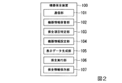
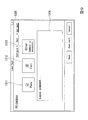
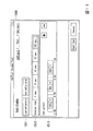
次に、図2を用いて、機器保全装置の機能構成を説明する。図2は、実施形態における機器保全装置100の機能構成の一例を示すブロック図である。なお、以下の説明においては、図1を適宜参照する。
Next, the functional configuration of the device maintenance apparatus will be described with reference to FIG. FIG. 2 is a block diagram illustrating an example of a functional configuration of the
図2において、機器保全装置100は、通信部101、機器情報保管部102、保全項目特定部103、機器情報設定部104、表示データ生成部105、保全実行部106、及び保全情報保存部107の各機能を有する。機器保全装置100の上記各機能は、図1で示したCPU11においてプログラムを実行することによって実現することができる。すなわち、機器保全装置100の上記各機能は、ソフトウェアによって実現される機能モジュールである。
In FIG. 2, the
通信部101は、通信I/F16を介して、フィールド機器19との通信又は他の装置との通信を制御して、フィールド機器19の情報を取得する。通信部101が制御する通信によって、例えば、ISA100、HART、BRAIN等の規格のフィールド機器19のパラメータ(機器情報)の設定、パラメータの読出し、パラメータの確認等を行う。通信部101は、無線LAN通信、有線LAN通信、赤外線通信、近距離無線通信等の制御を行ってもよい。通信部101は、それぞれの通信に対応した制御を行うためのプログラムモジュールを有するものであってもよい。通信部101は、それぞれの通信に必要なプログラムモジュールを追加してインストールできるようにしてもよい。通信部101は、通信I/F16を介して接続されているフィールド機器19を自動的に認識して、認識したフィールド機器19のパラメータを取得することができる。
The
なお、フィールド機器19の情報の取得は、上述した通信による情報の取得に限定されるものではない。例えば、作業者が目視でフィールド機器19のタグ名やモデル名を確認してキー入力したり、機器保全装置1に備えつけのカメラでタグ名やモデル名の記載のあるフィールド機器19の銘板を撮影して、撮影画像からタグ名やモデル名を認識して取得したりするものであってもよい。
Note that the acquisition of information of the field device 19 is not limited to the acquisition of information by communication described above. For example, the operator visually confirms the tag name or model name of the field device 19 and inputs a key, or photographs the name plate of the field device 19 with the tag name or model name written on the
機器情報保管部102は、フィールド機器19の機器情報とこれに対応した保全項目の情報を保管する。機器情報保管部102において保管されるフィールド機器19のパラメータ(機器情報)は、例えば、フィールド機器19の機器タグ、機器アドレス、製造者、機器ID又は機器タイプ、モデル名、通信規格等のフィールド機器19を特定するための情報、若しくはフィールド機器19において測定された測定データ等である。
The device
機器情報保管部102において保管される保全項目は、フィールド機器19に設定されているパラメータの確認、フィールド機器19に対するパラメータの設定、所定の試験、所定の調整等である。保全項目には、保全項目の実施結果を報告するための報告書の出力等を含んでいてもよい。本実施形態において機器情報保管部102が保管する保全項目は、例えば、ループテスト(ループ試験)、ゼロ点調整、スパン調整、ワンタッチレポート、詳細な診断情報の表示、タグ/アドレス/ロール設定、設定制限の設定/解除、DTM(Device Type Manager)のインストール、DD(Device Description)のインストール、パラメータ取得、バルブのキャリブレーション、機器のスコーク、ISA100プロビジョニング、機器のオンサービス/オフサービス切替、サービスモード切替、バルブのパーシャルストロークテスト(部分作動検査)である。
The maintenance items stored in the device
機器情報保管部102は、それぞれのフィールド機器19とそのフィールド機器19において実行される保全項目とを対応付けて、対応付けた情報を読出し可能に保管する。機器情報保管部102は、1つのフィールド機器19に対して1又は複数の保全項目を対応付けることができる。上記保全項目の中には、所定のフィールド機器19において実行できる保全項目と実行できない保全項目とがある。例えば、バルブのキャリブレーションの保全項目は、バルブを有するフィールド機器19においては実行可能であるが、バルブを有さない温度計等のフィールド機器19においては実行できない。機器情報保管部102は、それぞれのフィールド機器19において実行可能な保全項目をフィールド機器19に対応付けて保管する。フィールド機器19の機器情報と保全項目との対応付けは、例えば、予め対応が設定された設定ファイルに基づき行うことができる。設定ファイルには、例えば機器タイプ、通信規格等の情報と保全項目を対応付けるものであってもよい。また、フィールド機器19と保全項目との対応付けは、作業者によって任意に設定できるようにしてもよい。フィールド機器19と保全項目との対応付けは、機器情報設定部104によって設定してもよい。
The device
なお、フィールド機器19においては、保全項目を対応付けない(0個の保全項目を対応付ける)場合があってもよい。例えば、故障中又は不使用中等のフィールド機器19に対しては、保全項目を対応付けないことを保管することにより保全作業が不要であることを示すことができる。機器情報保管部102は、対応付けた情報を、例えばHDD14に保管してもよい。
In the field device 19, there may be a case where maintenance items are not associated (zero maintenance items are associated). For example, it is possible to indicate that maintenance work is unnecessary for field devices 19 that are out of order or not in use by storing the fact that no maintenance item is associated. The device
保全項目特定部103は、通信部101において取得された機器の情報(「パラメータ」ともいう。)に基づき、機器情報保管部102に保管された保全項目の中からタッチパネル15に表示する保全項目を特定する。例えば、1つのフィールド機器19に対して、機器情報保管部102において5つの保全項目が対応付けられていた場合、保全項目特定部103は、対応付けられている5つの保全項目の中から3つの保全項目を特定する。保全項目の特定方法の詳細は、図3を用いて説明する。保全項目特定部103は、特定した保全項目を表示データ生成部105に出力する。
The maintenance
機器情報設定部104は、機器情報保管部102に保管するフィールド機器19のパラメータと保全項目を設定するためのUI(User Interface)を提供する。例えば、機器情報設定部104は、フィールド機器19のパラメータと保全項目の情報を通信I/F16を介して予め取得する。機器情報設定部104は、取得したフィールド機器19のパラメータと保全項目の情報をタッチパネル15に表示して、フィールド機器19と保全項目との対応付けを設定可能にする。機器情報設定部104は、設定された対応付けを機器情報保管部102に出力してもよい。
The device
表示データ生成部105は、通信部101によって通信接続されて取得されたフィールド機器19のパラメータをタッチパネル15に表示するための表示データを生成する。また、表示データ生成部105は、保全項目特定部103において特定された保全項目を、表示したフィールド機器19のパラメータに対応させて、フィールド機器19のパラメータとともに表示するための表示データを生成する。例えば、タッチパネル15において、保全項目はフィールド機器19のパラメータと対応付けて表示される。また、フィールド機器19が複数表示される場合、保全項目は夫々のフィールド機器19毎に表示されてもよい。なお、「表示するための表示データを生成する」ことを「表示する」と省略して説明する場合がある。また、表示データ生成部105は表示部と表現してもよい。すなわち、本実施形態における表示部とは、タッチパネル15のような表示装置であっても、表示装置で表示される表示データを生成するものであってもよい。
The display
また、表示データ生成部105は、接続されたフィールド機器19に対して特定された保全項目を実行させるための実行ボタンを表示するデータを生成する。実行ボタンとは、タッチパネル15に表示される操作の対象であり「操作部」の一実施形態である。実行ボタンを操作することによって保全項目が実行される。実行ボタンは、例えば、図形、文字、アイコン、記号等の形状で表示される。作業者は、タッチパネル15に表示された実行ボタンを操作することにより保全項目を実行させることができる。なお、図4においては、文字が表示された矩形の領域を持つ実行ボタンを例示する。作業者は、タッチパネル15の矩形の操作部の領域をタッチすることにより、保全項目を実行させることができる。実行ボタンは、プルダウンメニューによって選択される項目であってもよい。
Further, the display
また、表示データ生成部105は、表示する保全項目の実行ボタンに関する情報を表示するようにしてもよい。例えば、表示データ生成部105は、実行ボタンと、その実行ボタンで実行される保全項目の過去の実行結果を表示する。
Further, the display
保全実行部106は、表示データ生成部105によって表示され、作業者によって操作(例えば、ボタンの押下)がされた保全項目を実行させる。保全項目は、操作された保全項目毎に実行される。例えば、1つの保全項目が操作された場合、1つの保全項目が実行される。保全実行部106は、保全項目に関する設定、保全項目の進行状況の表示、又は保全項目の実行結果の表示等を行う。
The
保全情報保存部107は、保全実行部106で実行された保全項目の結果を保存する。保全項目の結果とは、例えば、保全項目の実行日時、保全項目の実行結果、保全項目の実行結果に基づく保全計画等である。保全情報保存部107において保存された保全項目の結果は、例えば、保全項目特定部103、保全実行部106等から取得される。
The maintenance
なお、図2においては、機器保全装置10が有する、通信部101、機器情報保管部102、保全項目特定部103、機器情報設定部104、表示データ生成部105、保全実行部106、及び保全情報保存部107の各機能がソフトウェアによって実現される場合を説明した。しかし、機器保全装置10が有する上記1つ以上の機能は、ハードウェアによって実現されるものであっても良い。また、機器保全装置10が有する上記各機能は、1つの機能を複数の機能に分割して実施してもよい。また、機器保全装置10が有する上記各機能は、2つ以上の機能を1つの機能に集約して実施してもよい。
以上で、図2を用いた、機器保全装置100の機能構成の説明を終了する。
In FIG. 2, the
Above, description of the function structure of the
次に、図3を用いて、機器保全装置10の動作を説明する。図3は、実施形態における機器保全装置10の動作の一例を示すフローチャートである。図3で説明する機器保全装置10の動作は、例えば、機器保全装置10のCPU11によって、図2で説明した各機能を実行することに実施することができる。なお、以下の説明においては、図1及び図2を適宜参照する。
Next, operation | movement of the
図3において、機器保全装置10は、通信接続処理を実行する(ステップS11)。通信接続処理は、通信I/F16に接続されたフィールド機器19に対して、通信部101が所定のプロトコルを介して通信接続することにより実行される。例えば、機器保全装置10は、所定の機器アドレスにおけるフィールド機器19と所定の通信プロトコルを介して接続する。
In FIG. 3, the
ステップS11の処理を実行した後、機器保全装置10は、接続されたフィールド機器19からパラメータ(機器情報)を取得する(ステップS12)。フィールド機器19からのパラメータの取得は、通信部101によって実行される。例えば、ステップS11において接続されたフィールド機器19が2台であった場合、通信部101は、2台のフィールド機器19から夫々パラメータを取得する。なお、ステップS11〜ステップS12においては、パラメータの取得は、通信I/F16を介して接続されたフィールド機器19から通信で取得する場合を示したが、パラメータの取得は、例えば、機器保全装置1に備え付けのカメラ、マイク等、通信以外の方法で取得してもよい。
After executing the process of step S11, the
ステップS12の処理を実行した後、機器保全装置10は、保全項目を検索する(ステップS13)。保全項目の検索は、保全項目特定部103によって実行することができる。保全項目の検索は、ステップS12において取得されたフィールド機器19のパラメータに基づき、機器情報保管部102に保管されたフィールド機器19と保全項目とを対応付けた情報を用いて行われる。例えば、ステップS12において2台分のフィールド機器19のパラメータが取得された場合、機器保全装置10は、2台分のフィールド機器19の夫々のパラメータに対応した保全項目を検索し、2台分の検索結果を取得する。
After executing the process of step S12, the
ステップS13の処理を実行した後、機器保全装置10は、タッチパネル15に実行ボタンとして表示する保全項目を特定する(ステップS14)。ステップS14における保全項目の特定は、例えば、特定された保全項目の実行ボタンをタッチパネル15に表示するか否かの決定である。また、保全項目の特定は、タッチパネル15に表示する実行ボタンの表示順序を決定するものであってもよい。ここで保全項目の特定方法を説明する。以下に例示する保全項目の特定方法は、いずれか1つ又は2以上を組み合わせて実施することができる。
After executing the process of step S13, the
[作業者の任意設定による保全項目の特定]
ステップS14の処理における保全項目の特定を、予め作業者によって任意に設定された設定に基づき実行する。例えば、作業者は、タッチパネル15に表示された1のフィールド機器19を選択し、選択したフィールド機器19に対応して表示される実行ボタンを、タッチパネル15に表示された保全項目の選択画面から選択する。選択された保全項目は、例えば機器情報保管部102に保管される。保全項目特定部103は、保管された保全項目に従い、タッチパネル15に実行ボタンとして表示する保全項目を特定する。なお、この保全項目の特定方法は図5を用いて後述する。
[Identification of maintenance items by manual setting of workers]
The identification of the maintenance item in the process of step S14 is executed based on the setting arbitrarily set in advance by the operator. For example, the operator selects one field device 19 displayed on the
[保全項目の実施結果に基づく保全項目の特定]
ステップS14の処理における保全項目の特定を、保全項目の実施結果に基づき実行する。例えば、前回の保全項目の実施において異常が発見された保全項目を機器情報保管部102に保管する。保全項目特定部103は、保管された異常が発見された保全項目に基づき、タッチパネル15に実行ボタンとして表示する保全項目を特定する。
[Identification of maintenance items based on the implementation results of maintenance items]
The identification of the maintenance item in the process of step S14 is executed based on the execution result of the maintenance item. For example, a maintenance item in which an abnormality is found in the previous maintenance item implementation is stored in the device
[保全項目の実施頻度に基づく保全項目の特定]
ステップS14の処理における保全項目の特定を、保全項目の実施結果に基づき実行する他の一例として、保全項目の実施頻度に基づき実行する。例えば、作業者が良く実施する保全項目を機器情報保管部102に保管する。良く実施する保全項目は、例えば保全項目の実施結果に基づき過去数か月の間に実行された回数によって判断してもよい。保全項目特定部103は、保管された良く実施する保全項目に基づき、タッチパネル15に実行ボタンとして表示する保全項目を特定する。
[Identification of maintenance items based on the frequency of maintenance items]
As another example of executing the identification of the maintenance item in the process of step S14 based on the execution result of the maintenance item, the maintenance item is executed based on the execution frequency of the maintenance item. For example, maintenance items often performed by the worker are stored in the device
[保全項目の実施計画に基づく保全項目の特定]
ステップS14の処理における保全項目の特定を、保全項目の実施計画に基づき実行する。例えば、保全項目の実施計画(保全計画)が予め作成されていた場合、保全計画を機器情報保管部102に保管する。保全項目特定部103は、保管された保全計画に基づき、タッチパネル15に実行ボタンとして表示する保全項目を特定する。実行された保全項目は、特定の対象から外すようにしてもよい。
[Identification of maintenance items based on the maintenance item implementation plan]
The maintenance item in the process of step S14 is specified based on the maintenance item execution plan. For example, when a maintenance item execution plan (maintenance plan) is created in advance, the maintenance plan is stored in the device
ステップS14の処理を実行した後、機器保全装置10は、ステップS12において取得されたフィールド機器19のパラメータをタッチパネル15に表示する(ステップS15)。ステップS15の処理においてタッチパネル15に表示されるフィールド機器19のパラメータは、例えば、フィールド機器19の機器タグ、機器ID等の基本情報、フィールド機器19から取得した測定データ等である。
After executing the process of step S14, the
ステップS15の処理を実行した後、機器保全装置10は、ステップS14の処理において特定された保全項目の実行ボタンを、ステップS14の処理において表示されたフィールド機器19のパラメータとともにタッチパネル15に表示する(ステップS16)。特定された保全項目の実行ボタンをフィールド機器19のパラメータとともに表示することにより、表示されたフィールド機器19に対する保全項目をワンタッチで実行することができる。
After executing the processing of step S15, the
ステップS16の処理を実行した後、機器保全装置10は、ステップS12の処理で実行したフィールド機器19の情報の再取得を実行するから否かを判断する(ステップS17)。例えば、作業者が機器保全装置1を別の機器アドレスのフィールド機器19に繋ぎ替えた場合、フィールド機器19の情報の再取得が必要になる。機器保全装置10は、作業者からの明示的な指示の有無によって、又は通信I/F16の接続状況の変化を自動的に検出することによって、再取得の要否を判断してもよい。再取得を実行すると判断した場合(ステップS17:YES)、機器保全装置10は、ステップS11の処理に戻り、フィールド機器19の情報の再取得を実行する。
After executing the process of step S16, the
一方、再取得を実行しないと判断した場合(ステップS17:NO)、機器保全装置10は、保全項目を編集するか否かを判断する。保全項目によっては、保全項目を実行するための種々の設定項目が必要となる。保全項目を編集することにより、保全項目を実行するための設定項目の再設定が可能となる。機器保全装置10は、作業者からの明示的な指示の有無によって、又は設定項目がない保全項目であるか否かによって保全項目を編集するか否かを判断してもよい。
On the other hand, when it is determined not to execute the reacquisition (step S17: NO), the
保全項目を編集すると判断した場合、機器保全装置10は、保全項目編集のためのUIを、タッチパネル15を介して提供する(ステップS22)。ステップS22の処理を実行した後、機器保全装置10は、ステップS16の処理において保全項目を再度表示する。
If it is determined that the maintenance item is to be edited, the
一方、保全項目を編集しないと判断した場合、機器保全装置10は、保全項目の実行ボタンが作業者によって押下(操作)されたか否かを判断する(ステップS23)。保全項目の実行ボタンが作業者によって押下されたか否かは、例えば、保全実行部106がタッチパネル15の操作イベントを監視することにより実施することができる。
On the other hand, when it is determined that the maintenance item is not edited, the
実行ボタンが作業者によって操作されたと判断した場合(ステップS23:YES)、機器保全装置10は、押下された実行ボタンに対応する保全項目を実行する(ステップS24)。なお、保全項目の実行は、実行ボタンが押下された後に直ちに実行されてもよく、又は、実行ボタンが押下された後に他の表示や操作がされた後に実行されてもよい。例えば、保全項目は、実行ボタンが押下された後に、タッチパネル15の表示が後述する図6の表示に遷移して、図6のスタートボタン1131を押下することで実行されてもよい。また、保全項目は、実行ボタンが押下された後に、実行を行うか否かを確認する表示や、実行に関する内容を編集可能に表示して、これらの表示に対する操作をしてから実行されてもよい。
When it is determined that the execution button has been operated by the operator (step S23: YES), the
保全項目の実行は、保全実行部106によって実施することができる。ステップS24の処理を実行した後、機器保全装置10は、実行された保全項目の結果を保存する(ステップS25)。実行された保全項目の結果の保存は、保全情報保存部107によって実施することができる。ステップS25の処理を実行した後、機器保全装置10は、ステップS14の処理に戻り、保全項目の特定を再度実行する。すなわち、ステップS14の処理における保全項目の特定は、実行された保全項目の結果に応じて再度実行されることになる。保全項目の特定を再度実行することにより、例えば、タッチパネル15において、実行済みの保全項目の実行ボタンの表示を消去したり、実行済みの保全項目の実行ボタンの表示順序を変更したり、又は他の保全項目の実行ボタンを表示したりすることが可能となる。
The maintenance item can be executed by the
一方、実行ボタンが作業者によって操作されていないと判断した場合(ステップS23:NO)、機器保全装置10は、図3で示すフローチャートの処理を終了するか否かを判断する(ステップS26)。処理を終了するか否かの判断は、例えば、タッチパネル15の表示画面が保全項目を実行することが可能な表示画面から他の表示画面に切替ったか否か、電源スイッチがOFFにされたか否か等を検出することにより実施することができる。処理を終了しないと判断した場合(ステップS26:NO)、機器保全装置10は、ステップS16に戻って処理を実行する。一方、処理を終了すると判断した場合(ステップS26:YES)、機器保全装置10は、図3で示すフローチャートの処理を終了する。
以上で、図3を用いた、機器保全装置10の動作の説明を終了する。
On the other hand, when it is determined that the execution button has not been operated by the operator (step S23: NO), the
Above, description of operation | movement of the
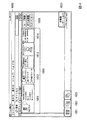
次に、図4を用いて、機器保全装置1のタッチパネル15に表示される保全項目の実行ボタンについて説明する。図4は、実施形態における機器保全装置10が表示する、保全項目の実行ボタンの一例を示す図である。
Next, a maintenance item execution button displayed on the
図4において、タッチパネル15の表示画面には、メイン画面1000が表示されている。メイン画面1000は、例えば、機器保全装置1が起動された後に最初に表示される表示である。メイン画面1000は、機器保全装置1が起動された後に、図示しないログイン画面においてログイン操作が行われた後、又は初期設定がされた後に表示されるものであってもよい。
In FIG. 4, a
メイン画面1000は、フィールド機器19のパラメータを表示及び登録する画面である。メイン画面1000は、機器基本情報表示1011、パラメータ取得ボタン1012、メモ/画像表示1013、パラメータ表示1014、及び保全項目ボタン1015の表示を有する。ここで、機器基本情報表示1011、パラメータ取得ボタン1012、メモ/画像表示1013及びパラメータ表示1014を、以下「機器情報1010」という。保全項目ボタン1015は、メイン画面1000において、機器情報1010の右側に、機器情報1010とともに表示される。メイン画面1000は、表示データ生成部105が生成した表示データによってタッチパネル15に表示される。
The
図4はフィールド機器19が1台接続されている場合を示している。機器情報1010は、フィールド機器19が複数接続されている場合には、接続されたフィールド機器の台数分が表示される。保全項目ボタン1015は、機器情報1010が複数台数分表示されたときには、それぞれの機器情報1010の図4図示右側に表示される。
FIG. 4 shows a case where one field device 19 is connected. The
機器基本情報表示1011は、接続されたフィールド機器19の、アイコン、機器タグ、製造者、機器アドレス、機器ID、ライトプロテクトの状態等を表示する。パラメータ取得ボタン1012は、全パラメータ又はゼロ点調整のパラメータを取得するための実行ボタン、取得したパラメータを外部ファイルに出力するためのボタンを有する。メモ/画像表示1013は、保全対象のフィールド機器19に対して予め入力されたコメント(メモ)を表示するコメント表示欄と、フィールド機器19の写真を表示する写真表示欄とを有する。パラメータ表示1014は、フィールド機器19から取得したパラメータを表示する。
The device
保全項目ボタン1015は、ループ試験の保全項目を実行するための「ループ試験」の実行ボタン、ゼロ点調整の保全項目を実行するための「ゼロ点調整」の実行ボタン、及びワンタッチで保全報告書を出力するための「ワンタッチレポート」の実行ボタン(報告書出力操作部)を有する。「ループ試験」の実行ボタン、「ゼロ点調整」の実行ボタン、又は「ワンタッチレポート」の実行ボタンを操作することにより、保全項目をメイン画面1000から直接実行することが可能となる。なお、本実施形態における保全項目の実行の操作は、上述のようにメニュー項目等から複数回の画面遷移を伴った従来の保全項目の実行の操作と選択的に実行できるようにしてもよい。
The
また、保全項目ボタン1015は、過去に実行された保全項目の実行結果を表示するものであってもよい。例えば、ループ試験の実行ボタンの近傍に前回ループ試験が実行された日時、実行結果等を表示してもよい。
The
また、メイン画面1000は、全機器の保全報告書を出力するための「全機器レポート出力」の実行ボタン(報告書出力操作部)を有する。「ワンタッチレポート」の実行ボタンによって保全報告書をフィールド機器19毎に個別に出力できるとともに、「全機器レポート出力」の実行ボタンによって全てのフィールド機器19の保全報告書を一括して出力することが可能になる。
Further, the
メイン画面1000は、セグメントビューア切替ボタン1021、機器ナビゲータ切替ボタン1022、操作ログ切替ボタン1023を有する。メイン画面1000は、セグメントビューア切替ボタン1021が押下されている状態で表示される。なお、機器ナビゲータ切替ボタン1022は、機器情報設定部104において実行される機器情報の登録を行うための表示画面を表示する。また、操作ログ切替ボタン1023は、保全情報保存部107において保存された保全情報を表示するための表示画面を表示する。
以上で、図4を用いた、保全項目の実行ボタンについての説明を終了する。
The
This is the end of the description of the maintenance item execution button using FIG. 4.
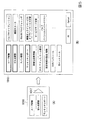
次に、図5を用いて、「作業者の任意設定による保全項目の特定」で説明した、保全項目の実行ボタンの設定画面を説明する。図5は、実施形態における機器保全装置が表示する、保全項目の実行ボタンの設定画面の一例を示す図である。 Next, with reference to FIG. 5, the setting screen for the maintenance item execution button described in “Specification of maintenance item by arbitrary setting of worker” will be described. FIG. 5 is a diagram illustrating an example of a maintenance item execution button setting screen displayed by the device maintenance apparatus according to the embodiment.
図5(A)において、保全項目ボタン1016は、図4で示した保全項目ボタン1015の他の実施態様である。保全項目ボタン1016は、フィールド機器19毎に表示される。保全項目ボタン1016は、保全項目ボタン1015の保全項目の実行ボタンに加えて、設定ボタン1017をさらに有する。設定ボタン1017は、保全項目ボタン1016に表示する保全項目の実行ボタンを作業者が任意に設定するためのボタンである。設定ボタン1017を作業者が操作すると、表示画面の表示が図5(A)から図5(B)に遷移する。
5A, a
図5(B)において、保全項目一覧1018には、ループテスト、ゼロ点調整、スパン調整、ワンタッチレポート、詳細な診断情報の表示、タグ/アドレス/ロール設定、設定制限の設定/解除、DTMのインストール、DDのインストール、バルブのキャリブレーション、機器のスコーク、ISA100プロビジョニング、機器のオンサービス/オフサービス切替、サービスモード切替、バルブのパーシャルストロークテスト等の保全項目が選択可能に表示される。図5(B)は、ループテスト、ゼロ点調整、及びワンタッチレポートの保全項目が選択状態であり、他の保全項目は非選択状態であることを示している。作業者は、保全項目ボタン1016に表示したい保全項目をタッチして選択状態を変更することができる。保全項目ボタン1016に表示可能な保全項目の数が3つである場合、既に選択状態にあるいずれかの保全項目を非選択状態とすることで、他の保全項目を選択状態とすることができる。保全項目ボタン1016に表示可能な保全項目の数は、任意に設定できるようにしてもよい。作業者は、保全項目の選択が完了した場合、OKボタンを押下する。OKボタンが押下されることにより、設定された保全項目が保管される。また、Cancelボタンが押下された場合、保全項目の変更はキャンセルされる。
In FIG. 5B, the
なお、本実施形態においてメイン画面1000に表示されるフィールド機器19は、機器保全装置1に接続されたものだけであり、接続されていないフィールド機器19はメイン画面1000に表示されない。図5で示した保全項目の実行ボタンの設定は、接続されていないフィールド機器19についても実行できるようにしてもよい。例えば、作業者が、機器情報保管部102に保管されたフィールド機器19のパラメータに基づき保全項目の実行ボタンの設定を行うフィールド機器19を選択できるようにしてもよい。
In the present embodiment, the field devices 19 displayed on the
保全項目ボタン1016に表示する保全項目の実行ボタンを、作業者がフィールド機器19毎に任意に設定できることにより、保全作業の効率向上を図ることができる。
以上で、図5を用いた、保全項目の実行ボタンの設定画面の説明を終了する。
The maintenance item execution button displayed on the
This is the end of the description of the maintenance item execution button setting screen shown in FIG.
次に、図6を用いて、ループテスト(ループ試験)の設定画面を説明する。図6は、実施形態における機器保全装置が表示する、ループテストの設定画面の一例を示す図である。ループテストとは、プラント等の制御系統において、フィールド機器19から所定の出力レベルの出力信号(テスト出力値)をDCS等の上位装置等に出力させ、フィールド機器19の動作や、フィールド機器19と上位装置等とが正しく結線されているかを確認するテストである。本実施形態ではループテストとして、出力信号の出力レベル(%)を、インターバル時間(秒)毎に変えるパターン(「テストパターン」という)を用いてテストする場合を説明する。テストパターンには、出力信号の出力レベルの他、インターバル時間、繰り返し回数等の情報を含んでいてもよい。図6はループテストで使用するテストパターンとして、出力信号のインターバル時間と出力レベルを設定するための設定画面を示す。 Next, a setting screen for a loop test (loop test) will be described with reference to FIG. FIG. 6 is a diagram illustrating an example of a loop test setting screen displayed by the device maintenance apparatus according to the embodiment. The loop test is a control system such as a plant in which an output signal (test output value) of a predetermined output level is output from a field device 19 to a host device such as a DCS, and the operation of the field device 19 This is a test to check whether the host device is connected correctly. In the present embodiment, as a loop test, a case will be described in which the output level (%) of an output signal is tested using a pattern (referred to as a “test pattern”) that changes every interval time (seconds). In addition to the output level of the output signal, the test pattern may include information such as the interval time and the number of repetitions. FIG. 6 shows a setting screen for setting the output signal interval time and output level as test patterns used in the loop test.
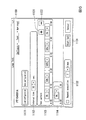
図6において、設定画面1100は、ロード/セーブ1111、インターバル時間設定1112、テストパターン設定1113、テストパターン設定1114、出力信号出力ブロック追加1121、出力信号出力ブロック削除1122、及びスタートボタン1131を有する。設定画面1100は、機器が出力する出力信号を時間の経過とともに変化させるテストパターンを設定可能にする設定操作部の一実施形態である。また、インターバル時間設定1112、テストパターン設定1113、テストパターン設定1114、出力信号出力ブロック追加1121、又は出力信号出力ブロック削除1122も機器が出力する出力信号を時間の経過とともに変化させるテストパターンを設定可能にする設定操作部の一実施形態である。すなわち、設定操作部は、機器が出力する出力信号を時間の経過とともに変化させるテストパターンを設定可能にするための、表示画面、ボタン等である。
6, the
ロード/セーブ1111は、設定画面1100で設定されたテストパターンをロード(読出し)又はセーブ(保存)するためのボタンである。作業者は、一度作成したテストパターンをセーブして、セーブしたテストパターンをロードすることにより、テストパターンを新たに設定するとき又は変更するときに、セーブしたテストパターンを参照することができる。また、複数のフィールド機器19に対して同じテストパターンでテストする場合、各機器に対するテスト毎に、セーブした同じテストパターンをロードすれば、テストパターンの作成に手間が省けて、より作業効率の向上を図ることができる。
A load / save 1111 is a button for loading (reading) or saving (saving) the test pattern set on the
インターバル時間設定1112は、テストパターンのインターバル時間を設定するためのプルダウンメニューである。インターバル時間は、プルダウンメニューによって、例えば、3秒、5秒、10秒、15秒、又は15秒にいずれかを選択することができる。図6では、インターバル時間がテキストボックスに10秒で設定されていることを示している。インターバル時間は、プルダウンメニューから選択して入力するようにしても、テキストボックスにキーボード等から直接数値を入力するようにしてもよい。インターバル時間設定1112において設定するインターバル時間は、1つの出力信号出力を保持する時間(出力時間)を表す。 The interval time setting 1112 is a pull-down menu for setting the interval time of the test pattern. The interval time can be selected from, for example, 3 seconds, 5 seconds, 10 seconds, 15 seconds, or 15 seconds by a pull-down menu. FIG. 6 shows that the interval time is set to 10 seconds in the text box. The interval time may be selected and input from a pull-down menu, or a numerical value may be input directly from a keyboard or the like in a text box. The interval time set in the interval time setting 1112 represents the time (output time) for holding one output signal output.
テストパターン設定1113は、テストパターンにおいて推移する出力レベルを設定するためのボタン(プルダウンメニューを含む)である。テストパターン設定1113は、出力レベルを設定するための出力信号出力ブロックを有する。図6は、5つの出力信号出力ブロックにおいて、出力レベルが、0%(10秒間)→50%(10秒間)→100%(10秒間)→50%(10秒間)→0%(10秒間)の5つのステップで推移する設定がされていることを示している。例えば、出力信号の出力が4〜20mAの間で出力される場合、0%=4mA、50%=12mA、100%=20mAの出力レベルで出力信号が出力される。具体的には、例えば、機器保全装置1は、フィールド機器19に対し、フィールド機器19から上位装置等へ0%(4mA)の電流を出力させるコマンド信号を送る。そして、このコマンド信号を受信したフィールド機器19は、インターバル時間の間、上位装置等へ0%(4mA)の電流を出力する。
The test pattern setting 1113 is a button (including a pull-down menu) for setting an output level that changes in the test pattern. The test pattern setting 1113 has an output signal output block for setting an output level. FIG. 6 shows that in five output signal output blocks, the output level is 0% (10 seconds) → 50% (10 seconds) → 100% (10 seconds) → 50% (10 seconds) → 0% (10 seconds) It is shown that the setting to change in the five steps is set. For example, when the output signal is output between 4 and 20 mA, the output signal is output at an output level of 0% = 4 mA, 50% = 12 mA, 100% = 20 mA. Specifically, for example, the
なお、図6は、テストパターンにおいて設定されるインターバル時間が、全ての出力信号出力ブロックで設定される出力レベルにおいて同一となる場合を示しているが、設定される出力信号出力ブロック毎又は出力レベル毎に異なるインターバル時間を設定できるようにしてもよい。 FIG. 6 shows the case where the interval time set in the test pattern is the same in the output levels set in all the output signal output blocks, but for each output signal output block to be set or the output level You may enable it to set a different interval time for every.
出力信号出力ブロック追加1121は、テストパターンにおける出力信号出力ブロックを追加するためのボタンである。出力信号出力ブロック削除1122は、テストパターンにおける出力信号出力ブロックを削除するためのボタンである。図6は、出力信号出力ブロック追加1121のボタン押下によって、テストパターン設定1114に6つ目の出力信号出力ブロックが追加されたことを示している。出力信号出力ブロック追加1121及び出力信号出力ブロック削除1122によって作業者は出力信号出力ブロックの数を任意に設定できることができる。
The output signal
スタートボタン1131は、ループテストを開始する(実行させる)ためのボタンである。スタートボタン1131は、設定されたテストパターンに基づく出力信号の出力を機器に対して実行させる実行操作部の一実施形態である。スタートボタン1131を押下することにより、ループテストをフィールド機器19に実行させて、図7に示すループテストの実行画面がタッチパネル15に表示される。
なお、リピート設定1132は、スタートボタン1131を押下したときに実行されるテストパターンに基づく出力信号の出力の繰り返し回数を設定する。作業者は、リピート設定1132のチェックボックスを選択することにより設定した回数にて、テストパターンに基づくテストを繰り返して実行させることができる。
以上で、図6を用いた、ループテストの設定画面の説明を終了する。
The
The repeat setting 1132 sets the number of output signal repetitions based on the test pattern executed when the
This is the end of the description of the loop test setting screen using FIG.
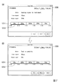
次に、図7及び図8を用いて、ループテストの実行画面を説明する。図7は、実施形態における機器保全装置1が表示する、ループテストの実行画面の一例を示す図である。図7(A)及び図7(B)は、実行画面1200におけるループテストの進行状況を示している。
Next, a loop test execution screen will be described with reference to FIGS. FIG. 7 is a diagram illustrating an example of a loop test execution screen displayed by the
図7(A)において、実行画面1200における「Status」の「Sending signal to instrument」の表示は、出力信号を送信中であることを示している。「Time elapsed」の「18sec」の表示は、テスト開始からの経過時間である。「Output signal」の「50%」の表示は、現在の出力信号の出力レベルが50%であることを示している。具体的には、例えば、機器保全装置1は、フィールド機器19に対し、フィールド機器19から上位装置等へ50%(12mA)の電流を出力させるコマンド信号を出力中であることを示す。
In FIG. 7A, the display of “Sending signal to instrument” of “Status” on the
出力信号出力ブロック1211は、図6の設定画面で設定されたテストパターンにおける出力信号の出力レベルを示している。プログレスバー1212は、ループテストの進行状況を示すグラフィカル表示である。図7(A)は、出力信号出力ブロックにおける2ステップ目において、50%の出力レベルで出力信号を出力中であることを示している。プログレスバー1212を表示することにより、作業者はループテストの進行状況を容易に把握することが可能となる。
The output
図7(B)は、図7(A)から時間が経過してループテストが終了したときの実行画面を示している。図7(B)において、実行画面1200における「Status」の「Test is complete」の表示は、ループテストが終了したことを示している。また、プログレスバー1212は、出力信号出力ブロックにおいて5ステップ目の0%の出力レベルでの出力信号の出力が終了したことを示している。
FIG. 7B shows an execution screen when the loop test is completed after a lapse of time from FIG. In FIG. 7B, the display of “Test is complete” of “Status” on the
図8は、実施形態における機器保全装置が表示する、ループテストの実行画面の他の一例を示す図である。 FIG. 8 is a diagram illustrating another example of a loop test execution screen displayed by the device maintenance apparatus according to the embodiment.
図8において、出力信号出力ブロック1221及びプログレスバー1222の機能は、図7においける出力信号出力ブロック1211及びプログレスバー1212と同様である。出力レベル表示1223は、出力信号出力ブロック1221において設定された出力レベルのグラフィカル表示である。図8は、出力レベルの0%、50%及び100%に合せて、出力レベル表示1223を折れ線グラフ状に表している。出力レベル表示1223を表示することにより、作業者は設定された出力レベルを容易に確認することが可能となる。
8, functions of the output
なお、図8では出力レベル表示1223を折れ線グラフ状に表示する場合を示したが、出力レベルに応じた、棒グラフでの表示、所定の領域の表示色の違い等により表示するようにしてもよい。また、スピーカ等から出力される音の違い、LEDランプの発行パターン等で出力レベルを報知するようにしてもよい。
以上で、図7及び図8を用いた、ループテストの実行画面の説明を終了する。
Although FIG. 8 shows the case where the
This is the end of the description of the loop test execution screen using FIGS. 7 and 8.
次に、図9及び図10を用いて、ループテストの結果入力画面とループテストの結果表示画面を説明する。図9は、実施形態における機器保全装置1が表示する、ループテストの結果入力画面の一例を示す図である。ループテストの結果入力画面とは、ループテストの結果を作業者が入力するための画面である。本実施形態におけるループテストは、テストパターンで出力された出力信号に対応した機器の入出力レベルや動作等のテスト結果を、作業者(機器保全装置1を操作する作業者と同一の作業者であっても異なる作業者であってもよい)が目視等で確認する。したがって、作業者が確認したループテストの結果は、作業者が手動で入力をする。図9は、作業者に対して提供される結果入力のためのUIを示している。具体的には、例えば、作業者は、フィールド機器19から上位装置等へ、実行指示した電流が出力されているかを確認する。
Next, a loop test result input screen and a loop test result display screen will be described with reference to FIGS. 9 and 10. FIG. 9 is a diagram illustrating an example of a loop test result input screen displayed by the
図9において、結果入力画面1300は、成功1311、失敗1312、その他1313の3種類の結果入力用のボタンを有する。また、結果入力画面1300は、コメント入力1314を有する。
In FIG. 9, the
ループテストが成功した場合、作業者は成功1311のボタンを押下する。ループテストが失敗した場合、作業者は失敗1312のボタンを押下する。また、ループテストの結果として、成功又は失敗以外の結果を記録したい場合、作業者はその他1313のボタンを押下して結果をテキストで残すことができる。成功1311、失敗1312又はその他1313のボタン押下の入力結果は、保全情報保存部107に保存される。
If the loop test is successful, the operator presses the
コメント入力1314は、作業者がコメントをテキスト入力するためのテキストボックスである。作業者は、成功又は失敗等の結果と合せて、ループテスト又はそのテスト対象の機器に対するコメントを残すことができる。コメント入力1314に入力されたコメントは、図4で説明したメモ/画像表示1013のコメント表示欄に付箋表示することができる。
The
図10は、実施形態における機器保全装置が表示する、ループテストの結果表示画面の一例を示す図である。図10の結果表示画面は、図9の結果入力画面においてループテストの結果が入力された後に表示される。 FIG. 10 is a diagram illustrating an example of a loop test result display screen displayed by the device maintenance apparatus according to the embodiment. The result display screen of FIG. 10 is displayed after the result of the loop test is input on the result input screen of FIG.
図10において、結果表示画面1400は、成功表示1411とコメント表示1412を有する。成功表示1411は、図9の結果入力画面1300において、成功1311のボタンが押下されたときに保全情報保存部107に保存された、入力結果として表示される。また、コメント表示1412は、図9の結果入力画面1300のコメント入力1314において入力されたテキストが表示される。
In FIG. 10, the
また、図10の上部には、ループテストの開始日時、終了日時、測定された最小値、最大値等のループテストのテスト結果が表示される。図10に表示されるこれらの結果は、図で説明した保全情報保存部107に保存される。
以上で、図9及び図10を用いた、ループテストの結果入力画面とループテストの結果表示画面の説明を終了する。
In addition, the test results of the loop test such as the start date / time and end date / time of the loop test, the measured minimum value, and the maximum value are displayed in the upper part of FIG. These results displayed in FIG. 10 are stored in the maintenance
The description of the loop test result input screen and the loop test result display screen using FIG. 9 and FIG. 10 is finished.
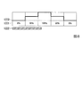
次に、図11を用いて、パーシャルストロークテストの設定画面を説明する。図11は、実施形態における機器保全装置が表示する、パーシャルストロークテストの設定画面の一例を示す図である。 Next, a partial stroke test setting screen will be described with reference to FIG. FIG. 11 is a diagram illustrating an example of a partial stroke test setting screen displayed by the device maintenance apparatus according to the embodiment.
パーシャルストロークテストとは、テスト対象のアクチュエータを部分的に動作させるテストである。パーシャルストロークテストにおいては、例えば、操業中のプラントの緊急遮断弁等のバルブの動作を確認するためにバルブを少しだけ動作させて、動作をするか否かを確認する。 The partial stroke test is a test in which the actuator to be tested is partially operated. In the partial stroke test, for example, in order to confirm the operation of a valve such as an emergency shut-off valve of an operating plant, the valve is operated a little to confirm whether or not the operation is performed.
図11において、設定画面1500は、図6における設定画面1100と同様にロード/セーブ1511、インターバル時間設定1512、テストパターン設定1513等を有する。図11は、テストパターン設定1513における出力信号出力ブロックにおいて、出力レベル(弁開度)が、100%(20秒間)→95%(20秒間)→100%(20秒間)と3つのステップで推移する設定がされていることを示している。すなわち、パーシャルストロークテストにおける設定画面1500においては、出力信号の出力レベルをパーシャルストロークテスト用の設定にすることにより、ループテストにおける設定画面1100と共通した設定画面を用いることができる。具体的には、例えば、機器保全装置1が弁開度を変化させる機器に対して、弁開度を100%にさせるコマンド信号を送る。
11, the
設定画面1500は、機器が出力する出力信号を時間の経過とともに変化させるテストパターンを設定可能にする設定操作部の一実施形態である。また、インターバル時間設定1512又はテストパターン設定1513も機器が出力する出力信号を時間の経過とともに変化させるテストパターンを設定可能にする設定操作部の一実施形態である。
パーシャルストロークテストにおいてもループテストと同様に実行画面、実行結果入力画面、及び実行結果表示画面を表示することができる。
The
In the partial stroke test, an execution screen, an execution result input screen, and an execution result display screen can be displayed as in the loop test.
なお、以上の説明ではフィールド機器19から出力させる出力信号として、ループテストとパーシャルストロークテストにおける出力信号を例示して説明したが、フィールド機器19から出力させる出力信号としては、ON/OFF信号のような接点信号、周波数やパルス幅を規定したパルス信号等がある。
以上で、図11を用いた、パーシャルストロークテストの設定画面の説明を終了する。
In the above description, the output signal in the loop test and the partial stroke test is illustrated as an output signal to be output from the field device 19, but the output signal to be output from the field device 19 is an ON / OFF signal. There are various contact signals, pulse signals defining the frequency and pulse width, and the like.
This is the end of the description of the partial stroke test setting screen using FIG.
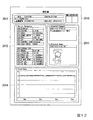
次に、図12を用いて、図4の保全項目ボタン1015で説明したワンタッチレポートの実行ボタンが押下されたときに出力される報告書を説明する。図12は、実施形態における機器保全装置が出力する、報告書の一例を示す図である。図12に示す報告書は、所定の電子データとして出力される。電子データとして出力された報告書は、例えば、タッチパネル15に出力されてもよい。また、電子データとして出力された報告書は、所定のファイルフォーマットの電子ファイルとして機器保全装置1の外部に出力されてもよく、また、プリンタから印字されて出力されてもよい。図12は、電子データとして出力されてプリンタから印字された報告書を示す。
Next, a report output when the execution button of the one-touch report described with reference to the
図12において、報告書2010は、第1情報2011、第2情報2012、第3情報2013及び第4情報2014を有する。
In FIG. 12, the
第1情報2011は、「形名」、「Tag No.」、「ループ名称」、「計器番号」、及び「記入日」等の情報を有する。
The
第2情報2012は、「Device Parameter」の情報を有する。例えばフィールド機器で用いる通信規格においてはそれぞれの通信規格に応じたパラメータの項目が定められている。報告書2010のDevice Parameterには、それぞれの通信規格に応じたパラメータの項目と項目の値を出力してもよい。
The
第3情報2013は、「Attached Comment」及び「Attached Image」の情報を有する。Attached Commentの情報は、図9で説明したコメント入力1314に任意に入力されたテキストを表示する。また、任意に入力されるフィールド機器19の写真である。第3情報2013の情報は、図4のメモ/画像表示1013で表示される情報である。
The
第4情報2014は、「Test Data」の情報を有する。Test Dataの情報は、例えば、保全項目の実行結果を集計した結果を表示するものであってもよい。図12は、所定の期間における保全項目の実行結果を集計し、実行日を横軸、測定値を縦軸にしてグラフ化した場合を示している。Test Dataは、保全項目の実行結果を表にして集計したものであってもよい。
The
図12は、Tag No.がPT1001で示される1つのフィールド機器に対する報告書を例示したが、複数のフィールド機器における報告書を出力するようにしてもよい。複数のフィールド機器に対する報告書は、例えばフィールド機器毎にページが分けられた複数ページの報告書とすることができる。また、表形式のファイルにおける複数シートの報告書としてもよい。 FIG. 12 shows Tag No. Exemplifies a report for one field device indicated by PT1001, but a report for a plurality of field devices may be output. The report for a plurality of field devices can be, for example, a multi-page report in which pages are divided for each field device. Alternatively, it may be a multi-sheet report in a tabular file.
また、複数のフィールド機器における報告書は、複数のフィールド機器を1ページの報告書にまとめて出力するようにしてもよい。例えば、フィールド機器を特定する第1情報2011と第2情報2012の中で注目すべきパラメータのみを表形式で出力するものであってもよい。 以上で、図12を用いた、出力される報告書の説明を終了する。
In addition, the reports for a plurality of field devices may be output in a single page of the plurality of field devices. For example, only the notable parameters in the
なお、本実施形態においては、表示部は、取得された機器の情報に対応付けて保管された保全項目の中の少なくとも一つの所定の保全項目を機器に対して実行させるための操作部を、取得された機器の情報とともに表示する場合として、機器情報と操作部をタッチパネル15に表示される場合を示したが、機器情報と操作部がともに表示される表示態様は図示した態様に限定されるものではない。例えば、機器情報と操作部が、タッチパネル15の表示画面に、同一の表示画面としてともに表示されるものであっても、スクロールによってともに表示されるものであってもよい。また、機器情報又は操作部が、アイコンや文字等の情報にタッチすることで別ウインドが起動して表示されたり、別ウインドに遷移又は切替って表示されたりすることでともに表示されるものであってもよい。また、表示パネルが複数配置されている場合、機器情報と操作部がそれぞれ別の表示パネルにおいてともに表示されるものであってもよい。また、機器情報とともに表示される操作部は、タッチパネル15における矩形等の所定の領域において表示される場合を示したが、例えば、操作部は、タッチパネル上での領域を特定せずに、タッチパネルに対する長押し、スワイプ、ピンチ等所定の操作を行うことにより操作可能な対象であってもよい。また、操作部は、ハードウェアスイッチ等に設けられたランプやディスプレイに表示されて、操作されるものであってもよい。
In the present embodiment, the display unit includes an operation unit for causing the device to execute at least one predetermined maintenance item among the maintenance items stored in association with the acquired device information. Although the case where the device information and the operation unit are displayed on the
また、図6のスタートボタン1131の表示は、図示した態様に限られない。例えば、スタートボタン1131の表示は、設定操作部として例示する設定画面1500等に対して、同一の表示画面での表示、スクロールしての表示、又は別ウインドでの表示等がなされてもよい。また、図6及び図7の表示態様も同様に、両図の表示が、同一の表示画面での表示、スクロールしての表示、又は別ウインドでの表示等がなされてもよい。
Further, the display of the
また、操作部の操作によって実行される保全項目として、フィールド機器19が記憶しているパラメータの取得を実行してもよい。フィールド機器19が記憶しているパラメータ取得の保全項目は、機器保全装置1からフィールド機器19に対してパラメータ取得用のコマンド信号を送信し、コマンド信号に応じてパラメータをフィールド機器19から取得して、取得したパラメータをタッチパネル15に表示するものであってもよい。
Moreover, you may perform the acquisition of the parameter which the field apparatus 19 has memorize | stored as a maintenance item performed by operation of an operation part. The parameter acquisition maintenance item stored in the field device 19 is a parameter acquisition command signal transmitted from the
また、保全項目は、フィールド機器19が記憶している情報(パラメータ、計測結果等)をワンタッチレポートの実行ボタンの押下によって報告書として出力するものであってもよい。ワンタッチレポートの実行ボタンの押下によって、機器保全装置1がフィールド機器19に対して情報取得用のコマンド信号を送信し、コマンド信号に応じて記憶している情報をフィールド機器19から取得して、取得した情報を報告書に含むように出力させてもよい。
In addition, the maintenance item may output information (parameters, measurement results, etc.) stored in the field device 19 as a report when a one-touch report execution button is pressed. By pressing the execution button of the one-touch report, the
また、本実施形態で説明した装置を構成する機能を実現するためのプログラムを、コンピュータ読み取り可能な記録媒体に記録して、当該記録媒体に記録されたプログラムをコンピュータシステムに読み込ませ、実行することにより、本実施形態の上述した種々の処理を行ってもよい。なお、ここでいう「コンピュータシステム」とは、OSや周辺機器等のハードウェアを含むものであってもよい。また、「コンピュータシステム」は、WWWシステムを利用している場合であれば、ホームページ提供環境(あるいは表示環境)も含むものとする。また、「コンピュータ読み取り可能な記録媒体」とは、フレキシブルディスク、光磁気ディスク、ROM、フラッシュメモリ等の書き込み可能な不揮発性メモリ、CD−ROM等の可搬媒体、コンピュータシステムに内蔵されるハードディスク等の記憶装置のことをいう。 Further, a program for realizing the functions constituting the apparatus described in the present embodiment is recorded on a computer-readable recording medium, and the program recorded on the recording medium is read into a computer system and executed. Thus, the various processes described above in the present embodiment may be performed. Here, the “computer system” may include an OS and hardware such as peripheral devices. Further, the “computer system” includes a homepage providing environment (or display environment) if a WWW system is used. The “computer-readable recording medium” means a flexible disk, a magneto-optical disk, a ROM, a writable nonvolatile memory such as a flash memory, a portable medium such as a CD-ROM, a hard disk built in a computer system, etc. This is a storage device.
さらに「コンピュータ読み取り可能な記録媒体」とは、インターネット等のネットワークや電話回線等の通信回線を介してプログラムが送信された場合のサーバやクライアントとなるコンピュータシステム内部の揮発性メモリ(例えばDRAM(Dynamic Random Access Memory))のように、一定時間プログラムを保持しているものも含むものとする。また、上記プログラムは、このプログラムを記憶装置等に格納したコンピュータシステムから、伝送媒体を介して、あるいは、伝送媒体中の伝送波により他のコンピュータシステムに伝送されてもよい。ここで、プログラムを伝送する「伝送媒体」は、インターネット等のネットワーク(通信網)や電話回線等の通信回線(通信線)のように情報を伝送する機能を有する媒体のことをいう。また、上記プログラムは、前述した機能の一部を実現するためのものであっても良い。さらに、前述した機能をコンピュータシステムにすでに記録されているプログラムとの組み合わせで実現するもの、いわゆる差分ファイル(差分プログラム)であっても良い。 Further, the “computer-readable recording medium” refers to a volatile memory (for example, DRAM (Dynamic) in a computer system serving as a server or a client when a program is transmitted via a network such as the Internet or a communication line such as a telephone line. Random Access Memory)) that holds a program for a certain period of time is also included. The program may be transmitted from a computer system storing the program in a storage device or the like to another computer system via a transmission medium or by a transmission wave in the transmission medium. Here, the “transmission medium” for transmitting the program refers to a medium having a function of transmitting information, such as a network (communication network) such as the Internet or a communication line (communication line) such as a telephone line. The program may be for realizing a part of the functions described above. Furthermore, what implement | achieves the function mentioned above in combination with the program already recorded on the computer system, and what is called a difference file (difference program) may be sufficient.
以上、本発明の実施形態について、図面を参照して説明してきたが、具体的な構成はこの実施形態に限定されるものではなく、本発明の趣旨を逸脱しない範囲においての種々の変更も含まれる。 The embodiment of the present invention has been described above with reference to the drawings. However, the specific configuration is not limited to this embodiment, and includes various modifications within the scope of the present invention. It is.
1、100 機器保全装置
11 CPU
12 RAM
13 ROM
14 HDD
15 タッチパネル
16 通信I/F
17 カードスロット
19 フィールド機器
101 通信部
102 機器情報保管部
103 保全項目特定部
104 機器情報設定部
105 表示データ生成部
106 保全実行部
107 保全情報保存部
1, 100
12 RAM
13 ROM
14 HDD
15
Claims (11)
前記機器の情報を取得する取得部と、
取得された前記機器の情報に対応付けて保管された前記保全項目の中の少なくとも一つの所定の保全項目を前記機器に対して実行させるための操作部を、取得された前記機器の情報とともに表示する表示部と
を備える、機器保全装置。 A device information storage unit for storing device information and maintenance items of the device in association with each other;
An acquisition unit for acquiring information on the device;
An operation unit for causing the device to execute at least one predetermined maintenance item among the maintenance items stored in association with the acquired device information is displayed together with the acquired device information. An apparatus maintenance apparatus comprising a display unit for performing the operation.
実行させた前記保全項目の結果を保存する保全情報保存部と
をさらに備える、請求項1に記載の機器保全装置。 A maintenance execution unit that executes a maintenance item corresponding to the operated operation unit according to the operation of the displayed operation unit;
The equipment maintenance apparatus according to claim 1, further comprising a maintenance information storage unit that stores a result of the executed maintenance item.
前記機器の情報を取得する取得ステップと、
取得された前記機器の情報に対応付けて保管された前記保全項目の中の少なくとも一つの所定の保全項目を前記機器に対して実行させるための操作部を、取得された前記機器の情報とともに表示する表示ステップと
を含む、機器保全方法。 A device information storage step for storing the device information and the maintenance items of the device in association with each other;
An acquisition step of acquiring information on the device;
An operation unit for causing the device to execute at least one predetermined maintenance item among the maintenance items stored in association with the acquired device information is displayed together with the acquired device information. A device maintenance method including a display step.
前記機器の情報を取得する取得処理と、
取得された前記機器の情報に対応付けて保管された前記保全項目の中の少なくとも一つの所定の保全項目を前記機器に対して実行させるための操作部を、取得された前記機器の情報とともに表示する表示処理と
をコンピュータに実行させるための、機器保全プログラム。 Device information storage processing for storing device information and maintenance items of the device in association with each other;
An acquisition process for acquiring the information of the device;
An operation unit for causing the device to execute at least one predetermined maintenance item among the maintenance items stored in association with the acquired device information is displayed together with the acquired device information. A device maintenance program for causing a computer to execute display processing.
前記機器の情報を取得する取得処理と、
取得された前記機器の情報に対応付けて保管された前記保全項目の中の少なくとも一つの所定の保全項目を前記機器に対して実行させるための操作部を、取得された前記機器の情報とともに表示する表示処理と
をコンピュータに実行させるための機器保全プログラムを記録した記録媒体。 Device information storage processing for storing device information and maintenance items of the device in association with each other;
An acquisition process for acquiring the information of the device;
An operation unit for causing the device to execute at least one predetermined maintenance item among the maintenance items stored in association with the acquired device information is displayed together with the acquired device information. The recording medium which recorded the apparatus maintenance program for making a computer perform the display process to perform.
Priority Applications (4)
| Application Number | Priority Date | Filing Date | Title |
|---|---|---|---|
| JP2016079151A JP2017191385A (en) | 2016-04-11 | 2016-04-11 | Instrument maintenance device, instrument maintenance method, instrument maintenance program, and recording medium |
| EP17165227.4A EP3232380B1 (en) | 2016-04-11 | 2017-04-06 | Device maintenance apparatus, method for maintaining device, and storage medium |
| US15/481,512 US20170293896A1 (en) | 2016-04-11 | 2017-04-07 | Device maintenance apparatus, method for maintaining device, and storage medium |
| CN201710223666.7A CN107291001B (en) | 2016-04-11 | 2017-04-07 | Instrument maintenance device, instrument maintenance method, and recording medium |
Applications Claiming Priority (1)
| Application Number | Priority Date | Filing Date | Title |
|---|---|---|---|
| JP2016079151A JP2017191385A (en) | 2016-04-11 | 2016-04-11 | Instrument maintenance device, instrument maintenance method, instrument maintenance program, and recording medium |
Related Child Applications (2)
| Application Number | Title | Priority Date | Filing Date |
|---|---|---|---|
| JP2019226523A Division JP6801771B2 (en) | 2019-12-16 | 2019-12-16 | Equipment maintenance equipment, equipment maintenance methods, equipment maintenance programs and recording media |
| JP2020040485A Division JP6856153B2 (en) | 2020-03-10 | 2020-03-10 | Equipment maintenance equipment, equipment maintenance methods, equipment maintenance programs and recording media |
Publications (1)
| Publication Number | Publication Date |
|---|---|
| JP2017191385A true JP2017191385A (en) | 2017-10-19 |
Family
ID=58664449
Family Applications (1)
| Application Number | Title | Priority Date | Filing Date |
|---|---|---|---|
| JP2016079151A Pending JP2017191385A (en) | 2016-04-11 | 2016-04-11 | Instrument maintenance device, instrument maintenance method, instrument maintenance program, and recording medium |
Country Status (4)
| Country | Link |
|---|---|
| US (1) | US20170293896A1 (en) |
| EP (1) | EP3232380B1 (en) |
| JP (1) | JP2017191385A (en) |
| CN (1) | CN107291001B (en) |
Cited By (1)
| Publication number | Priority date | Publication date | Assignee | Title |
|---|---|---|---|---|
| JP2022055661A (en) * | 2020-09-29 | 2022-04-08 | 横河電機株式会社 | Device maintenance apparatus, device maintenance method, and device maintenance program |
Families Citing this family (5)
| Publication number | Priority date | Publication date | Assignee | Title |
|---|---|---|---|---|
| JP6512452B2 (en) * | 2016-09-23 | 2019-05-15 | 京セラドキュメントソリューションズ株式会社 | Adjustment work support system |
| JP6787090B2 (en) * | 2016-12-02 | 2020-11-18 | 横河電機株式会社 | Maintenance management equipment, maintenance management methods, maintenance management programs and recording media |
| DE102018128698A1 (en) * | 2018-11-15 | 2020-05-20 | Amazonen-Werke H. Dreyer Gmbh & Co. Kg | Procedure for testing a technical device |
| US11868754B2 (en) | 2020-07-17 | 2024-01-09 | Sensia Llc | Systems and methods for edge device management |
| US11825308B2 (en) * | 2020-07-17 | 2023-11-21 | Sensia Llc | Systems and methods for security of a hydrocarbon system |
Citations (8)
| Publication number | Priority date | Publication date | Assignee | Title |
|---|---|---|---|---|
| JP2001333549A (en) * | 2000-03-15 | 2001-11-30 | Mitsubishi Electric Corp | Power system protective control system and system constructing method therfor |
| JP2007128308A (en) * | 2005-11-04 | 2007-05-24 | Denso Corp | Monitoring controller and monitoring control method |
| EP1906279A2 (en) * | 2006-09-27 | 2008-04-02 | Rockwell Automation Technologies, Inc. | Graphical interface for display of assets in an asset management system |
| JP2012208697A (en) * | 2011-03-29 | 2012-10-25 | Azbil Corp | Instrument monitoring unit |
| JP2013015899A (en) * | 2011-06-30 | 2013-01-24 | Mitsubishi Heavy Ind Ltd | Equipment inspection support system, equipment inspection support method, and program |
| JP2013535740A (en) * | 2010-07-28 | 2013-09-12 | フィッシャー−ローズマウント システムズ,インコーポレイテッド | Handheld field maintenance tool with improved diagnostics |
| US20150134289A1 (en) * | 2013-11-13 | 2015-05-14 | Fluke Corporation | Profiles for streamlining calibration test |
| JP2015109011A (en) * | 2013-12-05 | 2015-06-11 | 横河電機株式会社 | Field device management apparatus, device information display method, computer program, and recording medium |
Family Cites Families (4)
| Publication number | Priority date | Publication date | Assignee | Title |
|---|---|---|---|---|
| JP3689767B2 (en) * | 2000-09-22 | 2005-08-31 | 株式会社日立製作所 | Thermal power plant maintenance service provision method |
| US10410145B2 (en) * | 2007-05-15 | 2019-09-10 | Fisher-Rosemount Systems, Inc. | Automatic maintenance estimation in a plant environment |
| JP2013246534A (en) * | 2012-05-24 | 2013-12-09 | Mitsubishi Electric Corp | Adjustment test apparatus for ai module |
| US10551799B2 (en) * | 2013-03-15 | 2020-02-04 | Fisher-Rosemount Systems, Inc. | Method and apparatus for determining the position of a mobile control device in a process plant |
-
2016
- 2016-04-11 JP JP2016079151A patent/JP2017191385A/en active Pending
-
2017
- 2017-04-06 EP EP17165227.4A patent/EP3232380B1/en active Active
- 2017-04-07 CN CN201710223666.7A patent/CN107291001B/en active Active
- 2017-04-07 US US15/481,512 patent/US20170293896A1/en not_active Abandoned
Patent Citations (8)
| Publication number | Priority date | Publication date | Assignee | Title |
|---|---|---|---|---|
| JP2001333549A (en) * | 2000-03-15 | 2001-11-30 | Mitsubishi Electric Corp | Power system protective control system and system constructing method therfor |
| JP2007128308A (en) * | 2005-11-04 | 2007-05-24 | Denso Corp | Monitoring controller and monitoring control method |
| EP1906279A2 (en) * | 2006-09-27 | 2008-04-02 | Rockwell Automation Technologies, Inc. | Graphical interface for display of assets in an asset management system |
| JP2013535740A (en) * | 2010-07-28 | 2013-09-12 | フィッシャー−ローズマウント システムズ,インコーポレイテッド | Handheld field maintenance tool with improved diagnostics |
| JP2012208697A (en) * | 2011-03-29 | 2012-10-25 | Azbil Corp | Instrument monitoring unit |
| JP2013015899A (en) * | 2011-06-30 | 2013-01-24 | Mitsubishi Heavy Ind Ltd | Equipment inspection support system, equipment inspection support method, and program |
| US20150134289A1 (en) * | 2013-11-13 | 2015-05-14 | Fluke Corporation | Profiles for streamlining calibration test |
| JP2015109011A (en) * | 2013-12-05 | 2015-06-11 | 横河電機株式会社 | Field device management apparatus, device information display method, computer program, and recording medium |
Cited By (2)
| Publication number | Priority date | Publication date | Assignee | Title |
|---|---|---|---|---|
| JP2022055661A (en) * | 2020-09-29 | 2022-04-08 | 横河電機株式会社 | Device maintenance apparatus, device maintenance method, and device maintenance program |
| JP7327333B2 (en) | 2020-09-29 | 2023-08-16 | 横河電機株式会社 | Equipment maintenance device, equipment maintenance method, equipment maintenance program |
Also Published As
| Publication number | Publication date |
|---|---|
| CN107291001A (en) | 2017-10-24 |
| US20170293896A1 (en) | 2017-10-12 |
| CN107291001B (en) | 2019-12-24 |
| EP3232380A1 (en) | 2017-10-18 |
| EP3232380B1 (en) | 2020-02-19 |
Similar Documents
| Publication | Publication Date | Title |
|---|---|---|
| JP6688665B2 (en) | Equipment maintenance device, equipment maintenance method, equipment maintenance program and recording medium | |
| JP6732667B2 (en) | Maintenance work support device, maintenance work support method, maintenance work support program, and recording medium | |
| JP6468237B2 (en) | Equipment maintenance device, equipment maintenance method, equipment maintenance program, and recording medium | |
| JP2017191385A (en) | Instrument maintenance device, instrument maintenance method, instrument maintenance program, and recording medium | |
| JP6432551B2 (en) | Equipment maintenance device, equipment maintenance system, equipment maintenance method, equipment maintenance program, and recording medium | |
| US10949062B2 (en) | Device maintenance apparatus, device maintenance method, device maintenance program, and recording medium | |
| JP6708241B2 (en) | Equipment maintenance device, equipment maintenance method, equipment maintenance program and recording medium | |
| JP6536488B2 (en) | Apparatus maintenance apparatus, apparatus maintenance method, apparatus maintenance program and recording medium | |
| JP6856153B2 (en) | Equipment maintenance equipment, equipment maintenance methods, equipment maintenance programs and recording media | |
| JP6919679B2 (en) | Equipment maintenance equipment, equipment maintenance methods, equipment maintenance programs and recording media | |
| JP6801771B2 (en) | Equipment maintenance equipment, equipment maintenance methods, equipment maintenance programs and recording media | |
| JP6795080B2 (en) | Maintenance work support device, maintenance work support method, maintenance work support program and recording medium | |
| JP7028064B2 (en) | Equipment maintenance equipment, equipment maintenance methods, equipment maintenance programs and recording media | |
| JP6708240B2 (en) | Equipment maintenance device, equipment maintenance system, equipment maintenance method, equipment maintenance program and recording medium |
Legal Events
| Date | Code | Title | Description |
|---|---|---|---|
| A621 | Written request for application examination |
Free format text: JAPANESE INTERMEDIATE CODE: A621 Effective date: 20170501 |
|
| A131 | Notification of reasons for refusal |
Free format text: JAPANESE INTERMEDIATE CODE: A131 Effective date: 20180220 |
|
| A977 | Report on retrieval |
Free format text: JAPANESE INTERMEDIATE CODE: A971007 Effective date: 20180221 |
|
| A521 | Request for written amendment filed |
Free format text: JAPANESE INTERMEDIATE CODE: A523 Effective date: 20180423 |
|
| A131 | Notification of reasons for refusal |
Free format text: JAPANESE INTERMEDIATE CODE: A131 Effective date: 20180911 |
|
| A521 | Request for written amendment filed |
Free format text: JAPANESE INTERMEDIATE CODE: A523 Effective date: 20181026 |
|
| A131 | Notification of reasons for refusal |
Free format text: JAPANESE INTERMEDIATE CODE: A131 Effective date: 20190402 |
|
| A521 | Request for written amendment filed |
Free format text: JAPANESE INTERMEDIATE CODE: A523 Effective date: 20190513 |
|
| A131 | Notification of reasons for refusal |
Free format text: JAPANESE INTERMEDIATE CODE: A131 Effective date: 20191105 |
|
| A521 | Request for written amendment filed |
Free format text: JAPANESE INTERMEDIATE CODE: A523 Effective date: 20191216 |
|
| A02 | Decision of refusal |
Free format text: JAPANESE INTERMEDIATE CODE: A02 Effective date: 20200204 |