JP2017165289A - Vehicle control system, vehicle control method and vehicle control program - Google Patents
Vehicle control system, vehicle control method and vehicle control program Download PDFInfo
- Publication number
- JP2017165289A JP2017165289A JP2016052980A JP2016052980A JP2017165289A JP 2017165289 A JP2017165289 A JP 2017165289A JP 2016052980 A JP2016052980 A JP 2016052980A JP 2016052980 A JP2016052980 A JP 2016052980A JP 2017165289 A JP2017165289 A JP 2017165289A
- Authority
- JP
- Japan
- Prior art keywords
- vehicle
- mode
- automatic driving
- predicted
- timing
- Prior art date
- Legal status (The legal status is an assumption and is not a legal conclusion. Google has not performed a legal analysis and makes no representation as to the accuracy of the status listed.)
- Granted
Links
- 238000000034 method Methods 0.000 title claims description 28
- 230000001133 acceleration Effects 0.000 claims abstract description 29
- 238000001514 detection method Methods 0.000 claims description 38
- 238000004364 calculation method Methods 0.000 claims description 33
- 230000007704 transition Effects 0.000 claims description 28
- 238000012545 processing Methods 0.000 claims description 13
- 230000008859 change Effects 0.000 description 35
- 230000009471 action Effects 0.000 description 26
- 230000008569 process Effects 0.000 description 20
- 238000010586 diagram Methods 0.000 description 19
- 238000004891 communication Methods 0.000 description 15
- 238000003860 storage Methods 0.000 description 13
- 238000012544 monitoring process Methods 0.000 description 12
- 238000006243 chemical reaction Methods 0.000 description 5
- 230000007423 decrease Effects 0.000 description 4
- 238000011156 evaluation Methods 0.000 description 4
- 230000006870 function Effects 0.000 description 4
- 210000003128 head Anatomy 0.000 description 4
- 230000002093 peripheral effect Effects 0.000 description 4
- 230000033228 biological regulation Effects 0.000 description 3
- 238000002485 combustion reaction Methods 0.000 description 3
- 239000005357 flat glass Substances 0.000 description 3
- 239000000446 fuel Substances 0.000 description 3
- 230000005484 gravity Effects 0.000 description 3
- 238000003384 imaging method Methods 0.000 description 3
- 230000005540 biological transmission Effects 0.000 description 2
- 238000005401 electroluminescence Methods 0.000 description 2
- 238000005516 engineering process Methods 0.000 description 2
- 230000033001 locomotion Effects 0.000 description 2
- 238000004519 manufacturing process Methods 0.000 description 2
- 230000007246 mechanism Effects 0.000 description 2
- 208000019901 Anxiety disease Diseases 0.000 description 1
- LFQSCWFLJHTTHZ-UHFFFAOYSA-N Ethanol Chemical compound CCO LFQSCWFLJHTTHZ-UHFFFAOYSA-N 0.000 description 1
- UFHFLCQGNIYNRP-UHFFFAOYSA-N Hydrogen Chemical compound [H][H] UFHFLCQGNIYNRP-UHFFFAOYSA-N 0.000 description 1
- 206010039203 Road traffic accident Diseases 0.000 description 1
- 230000036506 anxiety Effects 0.000 description 1
- 230000001413 cellular effect Effects 0.000 description 1
- 230000000295 complement effect Effects 0.000 description 1
- 238000012790 confirmation Methods 0.000 description 1
- 238000010276 construction Methods 0.000 description 1
- 230000036461 convulsion Effects 0.000 description 1
- 239000013256 coordination polymer Substances 0.000 description 1
- 238000006073 displacement reaction Methods 0.000 description 1
- 230000008030 elimination Effects 0.000 description 1
- 238000003379 elimination reaction Methods 0.000 description 1
- 229910052739 hydrogen Inorganic materials 0.000 description 1
- 239000001257 hydrogen Substances 0.000 description 1
- 230000010354 integration Effects 0.000 description 1
- 230000009191 jumping Effects 0.000 description 1
- 239000004973 liquid crystal related substance Substances 0.000 description 1
- 239000002184 metal Substances 0.000 description 1
- 229910044991 metal oxide Inorganic materials 0.000 description 1
- 150000004706 metal oxides Chemical class 0.000 description 1
- 238000002360 preparation method Methods 0.000 description 1
- 230000001172 regenerating effect Effects 0.000 description 1
- 238000011160 research Methods 0.000 description 1
- 230000004044 response Effects 0.000 description 1
- 239000004065 semiconductor Substances 0.000 description 1
- 238000006467 substitution reaction Methods 0.000 description 1
- 230000009466 transformation Effects 0.000 description 1
Images


Classifications
-
- B—PERFORMING OPERATIONS; TRANSPORTING
- B60—VEHICLES IN GENERAL
- B60W—CONJOINT CONTROL OF VEHICLE SUB-UNITS OF DIFFERENT TYPE OR DIFFERENT FUNCTION; CONTROL SYSTEMS SPECIALLY ADAPTED FOR HYBRID VEHICLES; ROAD VEHICLE DRIVE CONTROL SYSTEMS FOR PURPOSES NOT RELATED TO THE CONTROL OF A PARTICULAR SUB-UNIT
- B60W60/00—Drive control systems specially adapted for autonomous road vehicles
- B60W60/005—Handover processes
- B60W60/0057—Estimation of the time available or required for the handover
-
- B—PERFORMING OPERATIONS; TRANSPORTING
- B60—VEHICLES IN GENERAL
- B60W—CONJOINT CONTROL OF VEHICLE SUB-UNITS OF DIFFERENT TYPE OR DIFFERENT FUNCTION; CONTROL SYSTEMS SPECIALLY ADAPTED FOR HYBRID VEHICLES; ROAD VEHICLE DRIVE CONTROL SYSTEMS FOR PURPOSES NOT RELATED TO THE CONTROL OF A PARTICULAR SUB-UNIT
- B60W10/00—Conjoint control of vehicle sub-units of different type or different function
- B60W10/04—Conjoint control of vehicle sub-units of different type or different function including control of propulsion units
-
- B—PERFORMING OPERATIONS; TRANSPORTING
- B60—VEHICLES IN GENERAL
- B60W—CONJOINT CONTROL OF VEHICLE SUB-UNITS OF DIFFERENT TYPE OR DIFFERENT FUNCTION; CONTROL SYSTEMS SPECIALLY ADAPTED FOR HYBRID VEHICLES; ROAD VEHICLE DRIVE CONTROL SYSTEMS FOR PURPOSES NOT RELATED TO THE CONTROL OF A PARTICULAR SUB-UNIT
- B60W10/00—Conjoint control of vehicle sub-units of different type or different function
- B60W10/20—Conjoint control of vehicle sub-units of different type or different function including control of steering systems
-
- B—PERFORMING OPERATIONS; TRANSPORTING
- B60—VEHICLES IN GENERAL
- B60W—CONJOINT CONTROL OF VEHICLE SUB-UNITS OF DIFFERENT TYPE OR DIFFERENT FUNCTION; CONTROL SYSTEMS SPECIALLY ADAPTED FOR HYBRID VEHICLES; ROAD VEHICLE DRIVE CONTROL SYSTEMS FOR PURPOSES NOT RELATED TO THE CONTROL OF A PARTICULAR SUB-UNIT
- B60W30/00—Purposes of road vehicle drive control systems not related to the control of a particular sub-unit, e.g. of systems using conjoint control of vehicle sub-units
- B60W30/14—Adaptive cruise control
- B60W30/16—Control of distance between vehicles, e.g. keeping a distance to preceding vehicle
-
- B—PERFORMING OPERATIONS; TRANSPORTING
- B60—VEHICLES IN GENERAL
- B60W—CONJOINT CONTROL OF VEHICLE SUB-UNITS OF DIFFERENT TYPE OR DIFFERENT FUNCTION; CONTROL SYSTEMS SPECIALLY ADAPTED FOR HYBRID VEHICLES; ROAD VEHICLE DRIVE CONTROL SYSTEMS FOR PURPOSES NOT RELATED TO THE CONTROL OF A PARTICULAR SUB-UNIT
- B60W30/00—Purposes of road vehicle drive control systems not related to the control of a particular sub-unit, e.g. of systems using conjoint control of vehicle sub-units
- B60W30/18—Propelling the vehicle
- B60W30/182—Selecting between different operative modes, e.g. comfort and performance modes
-
- B—PERFORMING OPERATIONS; TRANSPORTING
- B60—VEHICLES IN GENERAL
- B60W—CONJOINT CONTROL OF VEHICLE SUB-UNITS OF DIFFERENT TYPE OR DIFFERENT FUNCTION; CONTROL SYSTEMS SPECIALLY ADAPTED FOR HYBRID VEHICLES; ROAD VEHICLE DRIVE CONTROL SYSTEMS FOR PURPOSES NOT RELATED TO THE CONTROL OF A PARTICULAR SUB-UNIT
- B60W50/00—Details of control systems for road vehicle drive control not related to the control of a particular sub-unit, e.g. process diagnostic or vehicle driver interfaces
- B60W50/0097—Predicting future conditions
-
- B—PERFORMING OPERATIONS; TRANSPORTING
- B60—VEHICLES IN GENERAL
- B60W—CONJOINT CONTROL OF VEHICLE SUB-UNITS OF DIFFERENT TYPE OR DIFFERENT FUNCTION; CONTROL SYSTEMS SPECIALLY ADAPTED FOR HYBRID VEHICLES; ROAD VEHICLE DRIVE CONTROL SYSTEMS FOR PURPOSES NOT RELATED TO THE CONTROL OF A PARTICULAR SUB-UNIT
- B60W50/00—Details of control systems for road vehicle drive control not related to the control of a particular sub-unit, e.g. process diagnostic or vehicle driver interfaces
- B60W50/08—Interaction between the driver and the control system
- B60W50/082—Selecting or switching between different modes of propelling
-
- B—PERFORMING OPERATIONS; TRANSPORTING
- B60—VEHICLES IN GENERAL
- B60W—CONJOINT CONTROL OF VEHICLE SUB-UNITS OF DIFFERENT TYPE OR DIFFERENT FUNCTION; CONTROL SYSTEMS SPECIALLY ADAPTED FOR HYBRID VEHICLES; ROAD VEHICLE DRIVE CONTROL SYSTEMS FOR PURPOSES NOT RELATED TO THE CONTROL OF A PARTICULAR SUB-UNIT
- B60W50/00—Details of control systems for road vehicle drive control not related to the control of a particular sub-unit, e.g. process diagnostic or vehicle driver interfaces
- B60W50/08—Interaction between the driver and the control system
- B60W50/14—Means for informing the driver, warning the driver or prompting a driver intervention
-
- B—PERFORMING OPERATIONS; TRANSPORTING
- B60—VEHICLES IN GENERAL
- B60W—CONJOINT CONTROL OF VEHICLE SUB-UNITS OF DIFFERENT TYPE OR DIFFERENT FUNCTION; CONTROL SYSTEMS SPECIALLY ADAPTED FOR HYBRID VEHICLES; ROAD VEHICLE DRIVE CONTROL SYSTEMS FOR PURPOSES NOT RELATED TO THE CONTROL OF A PARTICULAR SUB-UNIT
- B60W60/00—Drive control systems specially adapted for autonomous road vehicles
- B60W60/005—Handover processes
- B60W60/0051—Handover processes from occupants to vehicle
-
- B—PERFORMING OPERATIONS; TRANSPORTING
- B60—VEHICLES IN GENERAL
- B60W—CONJOINT CONTROL OF VEHICLE SUB-UNITS OF DIFFERENT TYPE OR DIFFERENT FUNCTION; CONTROL SYSTEMS SPECIALLY ADAPTED FOR HYBRID VEHICLES; ROAD VEHICLE DRIVE CONTROL SYSTEMS FOR PURPOSES NOT RELATED TO THE CONTROL OF A PARTICULAR SUB-UNIT
- B60W60/00—Drive control systems specially adapted for autonomous road vehicles
- B60W60/005—Handover processes
- B60W60/0053—Handover processes from vehicle to occupant
-
- B—PERFORMING OPERATIONS; TRANSPORTING
- B60—VEHICLES IN GENERAL
- B60W—CONJOINT CONTROL OF VEHICLE SUB-UNITS OF DIFFERENT TYPE OR DIFFERENT FUNCTION; CONTROL SYSTEMS SPECIALLY ADAPTED FOR HYBRID VEHICLES; ROAD VEHICLE DRIVE CONTROL SYSTEMS FOR PURPOSES NOT RELATED TO THE CONTROL OF A PARTICULAR SUB-UNIT
- B60W50/00—Details of control systems for road vehicle drive control not related to the control of a particular sub-unit, e.g. process diagnostic or vehicle driver interfaces
- B60W2050/0062—Adapting control system settings
- B60W2050/007—Switching between manual and automatic parameter input, and vice versa
-
- B—PERFORMING OPERATIONS; TRANSPORTING
- B60—VEHICLES IN GENERAL
- B60W—CONJOINT CONTROL OF VEHICLE SUB-UNITS OF DIFFERENT TYPE OR DIFFERENT FUNCTION; CONTROL SYSTEMS SPECIALLY ADAPTED FOR HYBRID VEHICLES; ROAD VEHICLE DRIVE CONTROL SYSTEMS FOR PURPOSES NOT RELATED TO THE CONTROL OF A PARTICULAR SUB-UNIT
- B60W50/00—Details of control systems for road vehicle drive control not related to the control of a particular sub-unit, e.g. process diagnostic or vehicle driver interfaces
- B60W50/08—Interaction between the driver and the control system
- B60W50/14—Means for informing the driver, warning the driver or prompting a driver intervention
- B60W2050/146—Display means
-
- B—PERFORMING OPERATIONS; TRANSPORTING
- B60—VEHICLES IN GENERAL
- B60W—CONJOINT CONTROL OF VEHICLE SUB-UNITS OF DIFFERENT TYPE OR DIFFERENT FUNCTION; CONTROL SYSTEMS SPECIALLY ADAPTED FOR HYBRID VEHICLES; ROAD VEHICLE DRIVE CONTROL SYSTEMS FOR PURPOSES NOT RELATED TO THE CONTROL OF A PARTICULAR SUB-UNIT
- B60W2400/00—Indexing codes relating to detected, measured or calculated conditions or factors
-
- B—PERFORMING OPERATIONS; TRANSPORTING
- B60—VEHICLES IN GENERAL
- B60W—CONJOINT CONTROL OF VEHICLE SUB-UNITS OF DIFFERENT TYPE OR DIFFERENT FUNCTION; CONTROL SYSTEMS SPECIALLY ADAPTED FOR HYBRID VEHICLES; ROAD VEHICLE DRIVE CONTROL SYSTEMS FOR PURPOSES NOT RELATED TO THE CONTROL OF A PARTICULAR SUB-UNIT
- B60W2420/00—Indexing codes relating to the type of sensors based on the principle of their operation
- B60W2420/40—Photo, light or radio wave sensitive means, e.g. infrared sensors
- B60W2420/403—Image sensing, e.g. optical camera
-
- B—PERFORMING OPERATIONS; TRANSPORTING
- B60—VEHICLES IN GENERAL
- B60W—CONJOINT CONTROL OF VEHICLE SUB-UNITS OF DIFFERENT TYPE OR DIFFERENT FUNCTION; CONTROL SYSTEMS SPECIALLY ADAPTED FOR HYBRID VEHICLES; ROAD VEHICLE DRIVE CONTROL SYSTEMS FOR PURPOSES NOT RELATED TO THE CONTROL OF A PARTICULAR SUB-UNIT
- B60W2540/00—Input parameters relating to occupants
- B60W2540/225—Direction of gaze
-
- B—PERFORMING OPERATIONS; TRANSPORTING
- B60—VEHICLES IN GENERAL
- B60W—CONJOINT CONTROL OF VEHICLE SUB-UNITS OF DIFFERENT TYPE OR DIFFERENT FUNCTION; CONTROL SYSTEMS SPECIALLY ADAPTED FOR HYBRID VEHICLES; ROAD VEHICLE DRIVE CONTROL SYSTEMS FOR PURPOSES NOT RELATED TO THE CONTROL OF A PARTICULAR SUB-UNIT
- B60W2552/00—Input parameters relating to infrastructure
- B60W2552/53—Road markings, e.g. lane marker or crosswalk
-
- B—PERFORMING OPERATIONS; TRANSPORTING
- B60—VEHICLES IN GENERAL
- B60W—CONJOINT CONTROL OF VEHICLE SUB-UNITS OF DIFFERENT TYPE OR DIFFERENT FUNCTION; CONTROL SYSTEMS SPECIALLY ADAPTED FOR HYBRID VEHICLES; ROAD VEHICLE DRIVE CONTROL SYSTEMS FOR PURPOSES NOT RELATED TO THE CONTROL OF A PARTICULAR SUB-UNIT
- B60W2554/00—Input parameters relating to objects
- B60W2554/20—Static objects
-
- B—PERFORMING OPERATIONS; TRANSPORTING
- B60—VEHICLES IN GENERAL
- B60W—CONJOINT CONTROL OF VEHICLE SUB-UNITS OF DIFFERENT TYPE OR DIFFERENT FUNCTION; CONTROL SYSTEMS SPECIALLY ADAPTED FOR HYBRID VEHICLES; ROAD VEHICLE DRIVE CONTROL SYSTEMS FOR PURPOSES NOT RELATED TO THE CONTROL OF A PARTICULAR SUB-UNIT
- B60W2554/00—Input parameters relating to objects
- B60W2554/40—Dynamic objects, e.g. animals, windblown objects
- B60W2554/402—Type
- B60W2554/4029—Pedestrians
-
- B—PERFORMING OPERATIONS; TRANSPORTING
- B60—VEHICLES IN GENERAL
- B60W—CONJOINT CONTROL OF VEHICLE SUB-UNITS OF DIFFERENT TYPE OR DIFFERENT FUNCTION; CONTROL SYSTEMS SPECIALLY ADAPTED FOR HYBRID VEHICLES; ROAD VEHICLE DRIVE CONTROL SYSTEMS FOR PURPOSES NOT RELATED TO THE CONTROL OF A PARTICULAR SUB-UNIT
- B60W2554/00—Input parameters relating to objects
- B60W2554/40—Dynamic objects, e.g. animals, windblown objects
- B60W2554/406—Traffic density
-
- B—PERFORMING OPERATIONS; TRANSPORTING
- B60—VEHICLES IN GENERAL
- B60W—CONJOINT CONTROL OF VEHICLE SUB-UNITS OF DIFFERENT TYPE OR DIFFERENT FUNCTION; CONTROL SYSTEMS SPECIALLY ADAPTED FOR HYBRID VEHICLES; ROAD VEHICLE DRIVE CONTROL SYSTEMS FOR PURPOSES NOT RELATED TO THE CONTROL OF A PARTICULAR SUB-UNIT
- B60W2554/00—Input parameters relating to objects
- B60W2554/80—Spatial relation or speed relative to objects
- B60W2554/801—Lateral distance
-
- B—PERFORMING OPERATIONS; TRANSPORTING
- B60—VEHICLES IN GENERAL
- B60W—CONJOINT CONTROL OF VEHICLE SUB-UNITS OF DIFFERENT TYPE OR DIFFERENT FUNCTION; CONTROL SYSTEMS SPECIALLY ADAPTED FOR HYBRID VEHICLES; ROAD VEHICLE DRIVE CONTROL SYSTEMS FOR PURPOSES NOT RELATED TO THE CONTROL OF A PARTICULAR SUB-UNIT
- B60W2554/00—Input parameters relating to objects
- B60W2554/80—Spatial relation or speed relative to objects
- B60W2554/802—Longitudinal distance
-
- B—PERFORMING OPERATIONS; TRANSPORTING
- B60—VEHICLES IN GENERAL
- B60W—CONJOINT CONTROL OF VEHICLE SUB-UNITS OF DIFFERENT TYPE OR DIFFERENT FUNCTION; CONTROL SYSTEMS SPECIALLY ADAPTED FOR HYBRID VEHICLES; ROAD VEHICLE DRIVE CONTROL SYSTEMS FOR PURPOSES NOT RELATED TO THE CONTROL OF A PARTICULAR SUB-UNIT
- B60W2556/00—Input parameters relating to data
- B60W2556/40—High definition maps
-
- B—PERFORMING OPERATIONS; TRANSPORTING
- B60—VEHICLES IN GENERAL
- B60W—CONJOINT CONTROL OF VEHICLE SUB-UNITS OF DIFFERENT TYPE OR DIFFERENT FUNCTION; CONTROL SYSTEMS SPECIALLY ADAPTED FOR HYBRID VEHICLES; ROAD VEHICLE DRIVE CONTROL SYSTEMS FOR PURPOSES NOT RELATED TO THE CONTROL OF A PARTICULAR SUB-UNIT
- B60W2556/00—Input parameters relating to data
- B60W2556/45—External transmission of data to or from the vehicle
- B60W2556/50—External transmission of data to or from the vehicle of positioning data, e.g. GPS [Global Positioning System] data
-
- B—PERFORMING OPERATIONS; TRANSPORTING
- B60—VEHICLES IN GENERAL
- B60W—CONJOINT CONTROL OF VEHICLE SUB-UNITS OF DIFFERENT TYPE OR DIFFERENT FUNCTION; CONTROL SYSTEMS SPECIALLY ADAPTED FOR HYBRID VEHICLES; ROAD VEHICLE DRIVE CONTROL SYSTEMS FOR PURPOSES NOT RELATED TO THE CONTROL OF A PARTICULAR SUB-UNIT
- B60W2710/00—Output or target parameters relating to a particular sub-units
- B60W2710/20—Steering systems
-
- B—PERFORMING OPERATIONS; TRANSPORTING
- B60—VEHICLES IN GENERAL
- B60W—CONJOINT CONTROL OF VEHICLE SUB-UNITS OF DIFFERENT TYPE OR DIFFERENT FUNCTION; CONTROL SYSTEMS SPECIALLY ADAPTED FOR HYBRID VEHICLES; ROAD VEHICLE DRIVE CONTROL SYSTEMS FOR PURPOSES NOT RELATED TO THE CONTROL OF A PARTICULAR SUB-UNIT
- B60W2720/00—Output or target parameters relating to overall vehicle dynamics
- B60W2720/10—Longitudinal speed
- B60W2720/106—Longitudinal acceleration
Landscapes
- Engineering & Computer Science (AREA)
- Automation & Control Theory (AREA)
- Transportation (AREA)
- Mechanical Engineering (AREA)
- Human Computer Interaction (AREA)
- Chemical & Material Sciences (AREA)
- Combustion & Propulsion (AREA)
- Traffic Control Systems (AREA)
- Control Of Driving Devices And Active Controlling Of Vehicle (AREA)
- Remote Sensing (AREA)
- Aviation & Aerospace Engineering (AREA)
- Radar, Positioning & Navigation (AREA)
- Physics & Mathematics (AREA)
- General Physics & Mathematics (AREA)
- Evolutionary Computation (AREA)
- Game Theory and Decision Science (AREA)
- Medical Informatics (AREA)
- Artificial Intelligence (AREA)
- Health & Medical Sciences (AREA)
- Business, Economics & Management (AREA)
- Navigation (AREA)
- Steering Control In Accordance With Driving Conditions (AREA)
Abstract
Description
本発明は、車両制御システム、車両制御方法、および車両制御プログラムに関する。 The present invention relates to a vehicle control system, a vehicle control method, and a vehicle control program.
近年、目的地までの経路に沿って自車両が走行するように、自車両の加減速および操舵のうち、少なくとも一方を自動的に制御する技術(以下、「自動運転」という)についての研究が進められている。これに関連して、自動運転車両のシステム状態に基づいて自動運転レベルを判断し、その自動運転レベルに応じて、車両の操作部の画像および人における操作部を操作する部分の画像を同時に表示手段に表示させる表示制御手段を備えた情報表示装置が知られている(例えば、特許文献1参照)。 In recent years, research on a technology (hereinafter referred to as “automatic driving”) that automatically controls at least one of acceleration / deceleration and steering of a host vehicle so that the host vehicle travels along a route to a destination is performed. It is being advanced. In this connection, the automatic driving level is determined based on the system state of the autonomous driving vehicle, and the image of the operation unit of the vehicle and the image of the part operating the operation unit of the person are simultaneously displayed according to the automatic driving level. There is known an information display device provided with display control means for displaying on the means (see, for example, Patent Document 1).
しかしながら、従来の技術では、自動運転における各モードへの切り替えが、予め設定された切替条件が成立したタイミングで自動的に行われることで、車両乗員側で準備ができていないような状況が発生する可能性があった。 However, in the conventional technology, switching to each mode in automatic driving is automatically performed at the timing when a preset switching condition is satisfied, so that a situation where the vehicle occupant is not ready occurs. There was a possibility.
本発明は、このような事情を考慮してなされたものであり、自動運転の切り替わりタイミングを車両乗員に認識させることで、車両乗員に効率的な時間の使い方をさせることができる車両制御システム、車両制御方法、および車両制御プログラムを提供することを目的の一つとする。 The present invention has been made in consideration of such circumstances, and a vehicle control system that allows a vehicle occupant to efficiently use time by allowing the vehicle occupant to recognize the timing of switching automatic driving, An object is to provide a vehicle control method and a vehicle control program.
請求項1に記載の発明は、自車両の加減速および操舵のうち少なくとも一方を自動的に制御する自動運転制御部(120)であって、自動運転の度合が異なる複数のモードの何れかで自動運転制御を行う自動運転制御部と、前記自動運転のモードが前記自車両の走行環境に応じて前記複数のモードの何れかに遷移する場合に、前記モードが遷移するタイミングを予測し、予測したタイミングを報知する報知部(70、170)と、を備える車両制御システム(100)。
The invention according to
請求項2に記載の発明は、請求項1に記載の車両制御システムにおいて、前記報知部は、前記自動運転の度合が高い状態から低い状態に遷移するまでの継続時間を予測するものである。 According to a second aspect of the present invention, in the vehicle control system according to the first aspect, the notifying unit predicts a duration time until the degree of the automatic driving is changed from a high state to a low state.
請求項3に記載の発明は、請求項1または2に記載の車両制御システムにおいて、前記報知部は、前記自車両の現在の自動運転のモードから、前記自動運転の度合が高い自動運転のモードに変更されるタイミングまでの予測継続時間を報知するものである。 According to a third aspect of the present invention, in the vehicle control system according to the first or second aspect, the notification unit is configured to perform an automatic driving mode in which the degree of the automatic driving is high from the current automatic driving mode of the host vehicle. The predicted duration until the timing of the change is notified.
請求項4に記載の発明は、請求項1から3のうち、何れか1項に記載の車両制御システムにおいて、前記報知部は、前記モードが遷移するタイミングを報知することを、前記自動運転の度合が高い自動運転のモードに変更される前のモードの開始タイミングで開始するものである。 According to a fourth aspect of the present invention, in the vehicle control system according to any one of the first to third aspects of the present invention, the notification unit may notify the timing at which the mode transitions in the automatic driving. It starts at the start timing of the mode before the mode is changed to the automatic operation mode with a high degree.
請求項5に記載の発明は、請求項1から4のうち、何れか1項に記載の車両制御システムにおいて、前記報知部は、前記モードが遷移するタイミングを報知することを、前記自動運転の度合が高い自動運転のモードから前記自動運転の度合が低い自動運転のモードに変更されたタイミングで開始するものである。 According to a fifth aspect of the present invention, in the vehicle control system according to any one of the first to fourth aspects of the present invention, the notification unit notifies the timing at which the mode transitions in the automatic operation. The operation starts at the timing when the mode is changed from the automatic operation mode having a high degree to the automatic operation mode having a low degree of automatic operation.
請求項6に記載の発明は、請求項1から5のうち、何れか1項に記載の車両制御システムにおいて、前記報知部は、所定速度以下で前走車に追従して自動運転を行う渋滞追従走行モードの予測継続時間を報知するものである。 A sixth aspect of the present invention is the vehicle control system according to any one of the first to fifth aspects of the present invention, wherein the notification unit is a traffic jam that performs automatic driving following a preceding vehicle at a predetermined speed or less. The predicted duration time of the follow-up running mode is notified.
請求項7に記載の発明は、請求項3に記載の車両制御システムにおいて、前記報知部は、前記自車両の現在位置と、前記自車両が走行する目的地までの経路に関する交通情報とに基づいて、前記予測継続時間を算出する予測継続時間算出部(172)を備え、前記予測継続時間算出部により算出された予測継続時間を報知するものである。 A seventh aspect of the present invention is the vehicle control system according to the third aspect, wherein the notification unit is based on a current position of the host vehicle and traffic information on a route to the destination where the host vehicle travels. The prediction duration calculation unit (172) for calculating the prediction duration is provided, and the prediction duration calculated by the prediction duration calculation unit is notified.
請求項8に記載の発明は、請求項7に記載の車両制御システムにおいて、前記予測継続時間算出部は、一定時間ごとに、前記予測継続時間を算出するものである。 According to an eighth aspect of the present invention, in the vehicle control system according to the seventh aspect, the predicted duration calculation unit calculates the predicted duration every predetermined time.
請求項9に記載の発明は、請求項7または8に記載の車両制御システムにおいて、前記予測継続時間算出部は、前記自車両の現在位置と、前記交通情報から得られる渋滞が解消されると予測される位置とに基づいて、前記自車両が走行する経路上の距離を算出し、算出した距離と、前記自車両の車速とに基づいて第1の時間を算出するとともに、前記交通情報から得られる渋滞が解消されると予測される位置から所定の加速度で前記自車両を加速させて所定の速度に至るまでの第2の時間を算出し、算出した前記第1の時間と前記第2の時間とに基づいて前記予測継続時間を算出するものである。 According to a ninth aspect of the present invention, in the vehicle control system according to the seventh or eighth aspect, the predicted duration calculation unit is configured to eliminate a traffic jam obtained from the current position of the host vehicle and the traffic information. Based on the predicted position, a distance on the route on which the host vehicle travels is calculated, a first time is calculated based on the calculated distance and the vehicle speed of the host vehicle, and from the traffic information A second time from the position where the obtained traffic congestion is predicted to be accelerated to a predetermined speed by accelerating the host vehicle at a predetermined acceleration is calculated, and the calculated first time and second The predicted duration time is calculated based on the above time.
請求項10に記載の発明は、請求項1から9のうち、何れか1項に記載の車両制御システムにおいて、前記自車両内の乗員の視線方向を検出する視線検出部を更に備え、前記報知部は、前記視線検出部により検出された前記自車両の乗員の視線方向にあるインターフェース装置に前記モードが遷移するタイミングを報知するものである。 A tenth aspect of the present invention is the vehicle control system according to any one of the first to ninth aspects, further comprising a line-of-sight detection unit that detects a line-of-sight direction of an occupant in the host vehicle. The unit notifies the timing at which the mode transitions to the interface device in the sight line direction of the occupant of the host vehicle detected by the sight line detection unit.
請求項11に記載の発明は、車載コンピュータが、自車両の加減速および操舵のうち少なくとも一方を自動的に制御するとともに、自動運転の度合が異なる複数のモードの何れかで自動運転制御を行い、前記自動運転のモードが前記自車両の走行環境に応じて前記複数のモードの何れかに遷移する場合に、前記モードが遷移するタイミングを予測し、予測したタイミングを報知部に報知させる、車両制御方法である。 In the invention according to claim 11, the in-vehicle computer automatically controls at least one of acceleration / deceleration and steering of the host vehicle, and performs automatic driving control in any of a plurality of modes having different degrees of automatic driving. A vehicle that predicts the timing of transition of the mode when the mode of automatic driving transitions to any one of the plurality of modes according to the traveling environment of the host vehicle, and causes the notification unit to notify the predicted timing. It is a control method.
請求項12に記載の発明は、車載コンピュータに、自車両の加減速および操舵のうち少なくとも一方を自動的に制御するとともに、自動運転の度合が異なる複数のモードの何れかで自動運転制御を行い、前記自動運転のモードが前記自車両の走行環境に応じて前記複数のモードの何れかに遷移する場合に、前記モードが遷移するタイミングを予測し、予測したタイミングを報知部に報知させる、処理を実行させるための車両制御プログラムである。 In the invention according to claim 12, the in-vehicle computer automatically controls at least one of acceleration / deceleration and steering of the host vehicle, and performs automatic driving control in any of a plurality of modes having different degrees of automatic driving. When the mode of the automatic driving transitions to any one of the plurality of modes according to the traveling environment of the host vehicle, a process of predicting the timing of the mode transition and causing the notification unit to notify the predicted timing Is a vehicle control program for executing
請求項1、2、6、11、および12に記載の発明によれば、自動運転のモードが自車両の走行環境に応じて複数のモードの何れかに遷移するタイミングを報知することで、自車両の乗員に効率的な時間の使い方をさせることができる。 According to the first, second, sixth, eleventh and twelfth aspects of the present invention, by notifying the timing at which the automatic driving mode changes to one of a plurality of modes according to the traveling environment of the host vehicle, This makes it possible for the vehicle occupant to use the time efficiently.
請求項3の発明によれば、自動運転の度合が高い自動運転のモードに変更されるタイミングまでの予測継続時間を示す情報を報知することで、自動運転の切り替わりタイミングを自車両の乗員に認識させることができる。したがって、乗員に効率的な時間の使い方をさせることができる。 According to the invention of claim 3, by notifying the information indicating the predicted duration until the timing of changing to the automatic driving mode with a high degree of automatic driving, the occupant of the host vehicle recognizes the switching timing of the automatic driving. Can be made. Therefore, it is possible to allow the passenger to use time efficiently.
請求項4および5に記載の発明によれば、乗員は、自動運転の度合が低い状態がいつまで継続されるのかを、より確実に把握することができる。 According to the inventions described in claims 4 and 5, the occupant can more surely know how long the state of low degree of automatic driving will continue.
請求項7に記載の発明によれば、自車両が走行する目的地までの経路に関する交通情報に基づいて、より高精度に予測継続時間を出力することができる。 According to the seventh aspect of the invention, it is possible to output the predicted duration time with higher accuracy based on the traffic information related to the route to the destination where the host vehicle travels.
請求項8に記載の発明によれば、交通状況等の変化に応じた最新のモードの予測継続時間を出力することができる。 According to the eighth aspect of the invention, it is possible to output the predicted duration of the latest mode according to changes in traffic conditions and the like.
請求項9に記載の発明によれば、第1の時間と第2の時間とを考慮して、より正確な予測継続時間を算出することができる。 According to the ninth aspect of the invention, it is possible to calculate a more accurate predicted duration in consideration of the first time and the second time.
請求項10に記載の発明によれば、より確実に乗員に出力した情報を認識させることができる。 According to the tenth aspect of the present invention, information output to the occupant can be recognized more reliably.
以下、図面を参照し、本発明の車両制御システム、車両制御方法、および車両制御プログラムの実施形態について説明する。 Hereinafter, embodiments of a vehicle control system, a vehicle control method, and a vehicle control program of the present invention will be described with reference to the drawings.
<共通構成>
図1は、実施形態の車両制御システム100が搭載される車両(以下、自車両Mと称する)の構成要素を示す図である。車両制御システム100が搭載される車両は、例えば、二輪や三輪、四輪等の自動車であり、ディーゼルエンジンやガソリンエンジン等の内燃機関を動力源とした自動車や、電動機を動力源とした電気自動車、内燃機関および電動機を兼ね備えたハイブリッド自動車等を含む。電気自動車は、例えば、二次電池、水素燃料電池、金属燃料電池、アルコール燃料電池等の電池により放電される電力を使用して駆動される。
<Common configuration>
FIG. 1 is a diagram illustrating components of a vehicle (hereinafter referred to as a host vehicle M) on which the
図1に示すように、自車両Mには、ファインダ20−1から20−7、レーダ30−1から30−6、およびカメラ(撮像部)940等のセンサと、ナビゲーション装置(表示部)50と、車両制御システム100とが搭載される。
As shown in FIG. 1, the host vehicle M includes sensors such as a finder 20-1 to 20-7, radars 30-1 to 30-6, a camera (imaging unit) 940, and a navigation device (display unit) 50. And the
ファインダ20−1から20−7は、例えば、照射光に対する散乱光を測定し、対象までの距離を測定するLIDAR(Light Detection and Ranging、或いはLaser Imaging Detection and Ranging)である。例えば、ファインダ20−1は、フロントグリル等に取り付けられ、ファインダ20−2および20−3は、車体の側面やドアミラー、前照灯内部、側方灯付近等に取り付けられる。ファインダ20−4は、トランクリッド等に取り付けられ、ファインダ20−5および20−6は、車体の側面や尾灯内部等に取り付けられる。上述したファインダ20−1から20−6は、例えば、水平方向に関して150度程度の検出領域を有している。また、ファインダ20−7は、ルーフ等に取り付けられる。ファインダ20−7は、例えば、水平方向に関して360度の検出領域を有している。 The finders 20-1 to 20-7 are, for example, LIDAR (Light Detection and Ranging) that measures scattered light with respect to irradiation light and measures the distance to the target. For example, the finder 20-1 is attached to a front grill or the like, and the finders 20-2 and 20-3 are attached to a side surface of a vehicle body, a door mirror, the inside of a headlamp, a side lamp, and the like. The finder 20-4 is attached to a trunk lid or the like, and the finders 20-5 and 20-6 are attached to the side surface of the vehicle body, the interior of the taillight, or the like. The above-described finders 20-1 to 20-6 have a detection area of about 150 degrees in the horizontal direction, for example. The finder 20-7 is attached to a roof or the like. The finder 20-7 has a detection area of 360 degrees in the horizontal direction, for example.
レーダ30−1および30−4は、例えば、奥行き方向の検出領域が他のレーダよりも広い長距離ミリ波レーダである。また、レーダ30−2、30−3、30−5、30−6は、レーダ30−1および30−4よりも奥行き方向の検出領域が狭い中距離ミリ波レーダである。 The radars 30-1 and 30-4 are, for example, long-range millimeter wave radars having a detection area in the depth direction wider than that of other radars. Radars 30-2, 30-3, 30-5, and 30-6 are medium-range millimeter-wave radars that have a narrower detection area in the depth direction than radars 30-1 and 30-4.
以下、ファインダ20−1から20−7を特段区別しない場合は、単に「ファインダ20」と記載し、レーダ30−1から30−6を特段区別しない場合は、単に「レーダ30」と記載する。レーダ30は、例えば、FM−CW(Frequency Modulated Continuous Wave)方式によって物体を検出する。 Hereinafter, when the finders 20-1 to 20-7 are not particularly distinguished, they are simply referred to as “finder 20”, and when the radars 30-1 to 30-6 are not particularly distinguished, they are simply referred to as “radar 30”. The radar 30 detects an object by, for example, an FM-CW (Frequency Modulated Continuous Wave) method.
カメラ40は、例えば、CCD(Charge Coupled Device)やCMOS(Complementary Metal Oxide Semiconductor)等の個体撮像素子を利用したデジタルカメラである。カメラ40は、フロントウインドシールド上部やルームミラー裏面等に取り付けられる。カメラ40は、例えば、周期的に繰り返し自車両Mの前方を撮像する。カメラ40は、複数のカメラを含むステレオカメラであってもよい。
The
なお、図1に示す構成はあくまで一例であり、構成の一部が省略されてもよいし、更に別の構成が追加されてもよい。 The configuration illustrated in FIG. 1 is merely an example, and a part of the configuration may be omitted, or another configuration may be added.
図2は、車両制御システム100を中心とした機能構成図である。自車両Mには、ファインダ20、レーダ30、およびカメラ40等を含む検知デバイスDDと、ナビゲーション装置50と、通信装置55と、車両センサ60と、HMI(Human Machine Interface)70と、車両制御システム100と、走行駆動力出力装置200と、ステアリング装置210と、ブレーキ装置220とが搭載される。これらの装置や機器は、CAN(Controller Area Network)通信線等の多重通信線やシリアル通信線、無線通信網等によって互いに接続される。なお、特許請求の範囲における車両制御システムは、「車両制御システム100」のみを指しているのではなく、車両制御システム100以外の構成(検知デバイスDDやHMI70等)を含んでもよい。
FIG. 2 is a functional configuration diagram centering on the
ナビゲーション装置50は、GNSS(Global Navigation Satellite System)受信機や地図情報(ナビ地図)、ユーザインターフェースとして機能するタッチパネル式表示装置、スピーカ、マイク等を有する。ナビゲーション装置50は、GNSS受信機によって自車両Mの位置を推定し、その位置からユーザによって指定された目的地までの経路を導出する。ナビゲーション装置50により導出された経路は、車両制御システム100の目標車線決定部110に提供される。自車両Mの位置は、車両センサ60の出力を利用したINS(Inertial Navigation System)によって推定または補完されてもよい。また、ナビゲーション装置50は、車両制御システム100が手動運転モードを実行している際に、目的地に至る経路について音声やナビ表示によって案内を行う。なお、自車両Mの位置を推定するための構成は、ナビゲーション装置50とは独立して設けられてもよい。また、ナビゲーション装置50は、例えば、ユーザの保有するスマートフォンやタブレット端末等の端末装置の機能によって実現されてもよい。この場合、端末装置と車両制御システム100との間で、無線または有線による通信によって情報の送受信が行われる。
The
通信装置55は、例えば、セルラー網やWi−Fi網、Bluetooth(登録商標)、DSRC(Dedicated Short Range Communication)等を利用した無線通信を行う。通信装置55は、例えば無線通信により接続される外部装置から交通情報(例えば、渋滞情報)や天候情報等を取得することができる。
The
車両センサ60は、車速(走行速度)を検出する車速センサ、加速度を検出する加速度センサ、鉛直軸回りの角速度を検出するヨーレートセンサ、自車両Mの向きを検出する方位センサ等を含む。
The
図3は、HMI70の構成図である。HMI70は、例えば運転操作系の構成と、非運転操作系の構成とを備える。これらの境界は明確なものではなく、運転操作系の構成が非運転操作系の機能を備える(或いはその逆)ことがあってもよい。また、これらの運転操作系は、自車両Mの車両乗員(乗員)の操作を受け付ける操作受付部の一例である。また、非運転操作系には、インターフェース装置が含まれる。
FIG. 3 is a configuration diagram of the
HMI70は、運転操作系の構成として、例えばアクセルペダル71、アクセル開度センサ72およびアクセルペダル反力出力装置73と、ブレーキペダル74およびブレーキ踏量センサ(或いはマスター圧センサ等)75と、シフトレバー76およびシフト位置センサ77と、ステアリングホイール78、ステアリング操舵角センサ79およびステアリングトルクセンサ80と、その他運転操作デバイス81とを含む。
The
アクセルペダル71は、車両乗員による加速指示(或いは戻し操作による減速指示)を受け付けるための操作子である。アクセル開度センサ72は、アクセルペダル71の踏み込み量を検出し、踏み込み量を示すアクセル開度信号を車両制御システム100に出力する。なお、車両制御システム100に出力するのに代えて、走行駆動力出力装置200、ステアリング装置210、またはブレーキ装置220に直接出力することがあってもよい。以下に説明する他の運転操作系の構成についても同様である。アクセルペダル反力出力装置73は、例えば車両制御システム100からの指示に応じて、アクセルペダル71に対して操作方向と反対向きの力(操作反力)を出力する。
The
ブレーキペダル74は、車両乗員による減速指示を受け付けるための操作子である。ブレーキ踏量センサ75は、ブレーキペダル74の踏み込み量(或いは踏み込み力)を検出し、検出結果を示すブレーキ信号を車両制御システム100に出力する。
The
シフトレバー76は、車両乗員によるシフト段の変更指示を受け付けるための操作子である。シフト位置センサ77は、車両乗員により指示されたシフト段を検出し、検出結果を示すシフト位置信号を車両制御システム100に出力する。
The
ステアリングホイール78は、車両乗員による旋回指示を受け付けるための操作子である。ステアリング操舵角センサ79は、ステアリングホイール78の操作角を検出し、検出結果を示すステアリング操舵角信号を車両制御システム100に出力する。ステアリングトルクセンサ80は、ステアリングホイール78に加えられたトルクを検出し、検出結果を示すステアリングトルク信号を車両制御システム100に出力する。なお、ステアリングホイール78に関する制御として、例えば反力モータ等によりステアリング軸にトルクを出力することで、ステアリングホイール78に対して操作反力を出力してもよい。
The
その他運転操作デバイス81は、例えば、ジョイスティック、ボタン、ダイヤルスイッチ、GUI(Graphical User Interface)スイッチ等である。その他運転操作デバイス81は、加速指示、減速指示、旋回指示等を受け付け、車両制御システム100に出力する。
The
HMI70は、非運転操作系の構成として、例えば、表示装置(表示部)82、スピーカ83、接触操作検出装置84およびコンテンツ再生装置85と、各種操作スイッチ86と、シート88およびシート駆動装置89と、ウインドウガラス90およびウインドウ駆動装置91と、車室内カメラ(撮像部)95とを含む。
The
表示装置82は、例えば、インストルメントパネルの各部、助手席や後部座席に対向する任意の箇所等に取り付けられる、LCD(Liquid Crystal Display)や有機EL(Electro Luminescence)表示装置等である。また、表示装置82は、フロントウインドシールドやその他のウインドウに画像を投影するHUD(Head Up Display)であってもよい。スピーカ83は、音声を出力する。接触操作検出装置84は、表示装置82がタッチパネルである場合に、表示装置82の表示画面における接触位置(タッチ位置)を検出して、車両制御システム100に出力する。なお、表示装置82がタッチパネルでない場合、接触操作検出装置84は省略されてよい。
The
コンテンツ再生装置85は、例えば、DVD(Digital Versatile Disc)再生装置、CD(Compact Disc)再生装置、テレビジョン受信機、各種案内画像の生成装置等を含む。表示装置82、スピーカ83、接触操作検出装置84およびコンテンツ再生装置85は、一部または全部がナビゲーション装置50と共通する構成であってもよい。上述した表示装置82、スピーカ83、コンテンツ再生装置85、およびナビゲーション装置50は、何れもインターフェース装置の一例であるが、これらに限定されるものではない。
The content playback device 85 includes, for example, a DVD (Digital Versatile Disc) playback device, a CD (Compact Disc) playback device, a television receiver, and various guidance image generation devices. The
各種操作スイッチ86は、車室内の任意の箇所に配置される。各種操作スイッチ86には、自動運転の開始(或いは将来の開始)および停止を指示する自動運転切替スイッチ87を含む。自動運転切替スイッチ87は、GUI(Graphical User Interface)スイッチ、機械式スイッチの何れであってもよい。また、各種操作スイッチ86は、シート駆動装置89やウインドウ駆動装置91を駆動するためのスイッチを含んでもよい。
The various operation switches 86 are disposed at arbitrary locations in the vehicle interior. The various operation switches 86 include an automatic
シート88は、車両乗員が着座する座席シートである。シート駆動装置89は、シート88のリクライニング角、前後方向位置、ヨー角等を自在に駆動する。ウインドウガラス90は、例えば各ドアに設けられる。ウインドウ駆動装置91は、ウインドウガラス90を開閉駆動する。
The
車室内カメラ95は、CCDやCMOS等の個体撮像素子を利用したデジタルカメラである。車室内カメラ95は、バックミラーやステアリングボス部、インストルメントパネル等、運転操作を行う車両乗員の少なくとも頭部(顔を含む)を撮像可能な位置に取り付けられる。車室内カメラ95は、例えば、周期的に繰り返し車両乗員を撮像する。
The
車両制御システム100の説明に先立って、走行駆動力出力装置200、ステアリング装置210、およびブレーキ装置220について説明する。
Prior to the description of the
走行駆動力出力装置200は、車両が走行するための走行駆動力(トルク)を駆動輪に出力する。走行駆動力出力装置200は、例えば、自車両Mが内燃機関を動力源とした自動車である場合、エンジン、変速機、およびエンジンを制御するエンジンECU(Electronic Control Unit)を備え、自車両Mが電動機を動力源とした電気自動車である場合、走行用モータおよび走行用モータを制御するモータECUを備え、自車両Mがハイブリッド自動車である場合、エンジン、変速機、およびエンジンECUと走行用モータおよびモータECUとを備える。走行駆動力出力装置200がエンジンのみを含む場合、エンジンECUは、後述する走行制御部160から入力される情報に従って、エンジンのスロットル開度やシフト段等を調整する。走行駆動力出力装置200が走行用モータのみを含む場合、モータECUは、走行制御部160から入力される情報に従って、走行用モータに与えるPWM信号のデューティ比を調整する。走行駆動力出力装置200がエンジンおよび走行用モータを含む場合、エンジンECUおよびモータECUは、走行制御部160から入力される情報に従って、互いに協調して走行駆動力を制御する。
The traveling driving
ステアリング装置210は、例えば、ステアリングECUと、電動モータとを備える。電動モータは、例えば、ラックアンドピニオン機構に力を作用させて転舵輪の向きを変更する。ステアリングECUは、車両制御システム100から入力される情報、或いは入力されるステアリング操舵角またはステアリングトルクの情報に従って電動モータを駆動し、転舵輪の向きを変更させる。
The
ブレーキ装置220は、例えば、ブレーキキャリパーと、ブレーキキャリパーに油圧を伝達するシリンダと、シリンダに油圧を発生させる電動モータと、制動制御部とを備える電動サーボブレーキ装置である。電動サーボブレーキ装置の制動制御部は、走行制御部160から入力される情報に従って電動モータを制御し、制動操作に応じたブレーキトルクが各車輪に出力されるようにする。電動サーボブレーキ装置は、ブレーキペダルの操作によって発生させた油圧を、マスターシリンダを介してシリンダに伝達する機構をバックアップとして備えてよい。なお、ブレーキ装置220は、上記説明した電動サーボブレーキ装置に限らず、電子制御式油圧ブレーキ装置であってもよい。電子制御式油圧ブレーキ装置は、走行制御部160から入力される情報に従ってアクチュエータを制御して、マスターシリンダの油圧をシリンダに伝達する。また、ブレーキ装置220は、走行駆動力出力装置200に含まれ得る走行用モータによる回生ブレーキを含んでもよい。
The
[車両制御システム]
以下、車両制御システム100について説明する。車両制御システム100は、例えば、一以上のプロセッサまたは同等の機能を有するハードウェアにより実現される。車両制御システム100は、CPU(Central Processing Unit)等のプロセッサ、記憶装置、および通信インターフェースが内部バスによって接続されたECU(Electronic Control Unit)、或いはMPU(Micro-Processing Unit)等が組み合わされた構成であってよい。
[Vehicle control system]
Hereinafter, the
図2に戻り、車両制御システム100は、例えば、目標車線決定部110と、自動運転制御部120と、走行制御部160と、HMI制御部170と、記憶部180とを備える。自動運転制御部120は、例えば、自動運転モード制御部130と、自車位置認識部140と、外界認識部142と、行動計画生成部144と、軌道生成部146と、切替制御部150とを備える。目標車線決定部110、自動運転制御部120の各部、および走行制御部160のうち一部または全部は、プロセッサがプログラム(ソフトウェア)を実行することにより実現される。また、これらのうち一部または全部は、LSI(Large Scale Integration)やASIC(Application Specific Integrated Circuit)等のハードウェアによって実現されてもよいし、ソフトウェアとハードウェアの組み合わせによって実現されてもよい。
Returning to FIG. 2, the
記憶部180には、例えば、高精度地図情報182、目標車線情報184、行動計画情報186、およびモード別操作可否情報188等の情報が格納される。記憶部180は、ROM(Read Only Memory)やRAM(Random Access Memory)、HDD(Hard Disk Drive)、フラッシュメモリ等で実現される。プロセッサが実行するプログラムは、予め記憶部180に格納されていてもよいし、車載インターネット設備等を介して外部装置からダウンロードされてもよい。また、プログラムは、そのプログラムを格納した可搬型記憶媒体が図示しないドライブ装置に装着されることで記憶部180にインストールされてもよい。また、車両制御システム100のコンピュータ(車載コンピュータ)は、複数のコンピュータ装置によって分散化されたものであってもよい。
The
目標車線決定部110は、例えば、MPUにより実現される。目標車線決定部110は、ナビゲーション装置50から提供された経路を複数のブロックに分割し(例えば、車両進行方向に関して100[m]毎に分割し)、高精度地図情報182を参照してブロックごとに目標車線を決定する。目標車線決定部110は、例えば、左から何番目の車線を走行するといった決定を行う。目標車線決定部110は、例えば、経路において分岐箇所や合流箇所等が存在する場合、自車両Mが、分岐先に進行するための合理的な走行経路を走行できるように、目標車線を決定する。目標車線決定部110により決定された目標車線は、目標車線情報184として記憶部180に記憶される。
The target
高精度地図情報182は、ナビゲーション装置50が有するナビ地図よりも高精度な地図情報である。高精度地図情報182は、例えば、車線の中央の情報あるいは車線の境界の情報等を含んでいる。また、高精度地図情報182には、道路情報、交通規制情報、住所情報(住所・郵便番号・位置情報(緯度経度等))、施設情報、電話番号情報等が含まれてよい。道路情報には、高速道路、有料道路、国道、都道府県道といった道路の種別を表す情報や、道路の車線数、各車線の幅員、道路の勾配、道路の位置(経度、緯度、高さを含む3次元座標)、車線のカーブの曲率、車線の合流および分岐ポイントの位置、道路に設けられた標識等の情報が含まれる。交通規制情報には、工事や交通事故、渋滞等によって車線が封鎖されているといった情報が含まれる。高精度地図情報182は、定期的または不定期に通信装置55を介して外部装置等から最新の情報が取得され、記憶部180に記憶されてよい。
The high-
自動運転制御部120は、目的地までの経路に沿って自車両Mが走行するように、自車両Mの加減速および操舵のうち少なくとも一方を自動的に制御する。また、自動運転制御部120は、自動運転の度合が異なる複数のモードの何れかで自動運転制御を行う。なお、複数のモードは、例えば自車両Mの乗員に要求される周辺監視義務の度合が異なる複数のモードに対応していてもよく、また車両乗員の操作を受け付けるとともに情報を出力するHMI70の各インターフェース装置への操作許容度が異なる複数のモードに対応していてもよい。
The automatic
自動運転モード制御部130は、自動運転制御部120が実施する自動運転のモードを決定する。本実施形態における自動運転のモードには、以下のモードが含まれる。なお、以下はあくまで一例であり、自動運転のモード数やモード内容は任意に決定されてよい。
The automatic operation
[第1モード]
第1モードは、他のモードと比べて最も自動運転の度合が高いモードである。第1モードが実施されている場合、複雑な合流制御等、全ての車両制御が自動的に行われるため、車両乗員は自車両Mの周辺や状態を監視する必要がない(他のモードと比べて周辺監視義務の度合が低下する)。
[First mode]
The first mode is a mode having the highest degree of automatic driving compared to other modes. When the first mode is implemented, since all vehicle control such as complicated merge control is automatically performed, the vehicle occupant does not need to monitor the surroundings and state of the own vehicle M (compared to other modes). The extent of the obligation to monitor the surrounding area will decrease).
ここで、第1モードの一例としては、渋滞時に前走車両に追従する渋滞追従モード(低速追従モード)等がある。第1モードでは、例えばTJP(Traffic Jam Pilot)のように混雑した高速道路上で前走車両に追従することで安全な自動運転を実現することができ、また渋滞が解消したと予測される位置でTJPモードを終了させることができる。また、TJPモードを終了させるタイミングで第1モードが他のモードに切り替わる場合もあるが、TJPが終了した所定時間後に、第1のモードが切り替わってもよい。なお、第1のモードは、他のモードと比べて最もHMI70の各インターフェース装置(非運転操作系)の操作許容度が高いモードである。車両乗員は、第1モードにおいて使用が許可されているインターフェース装置(例えば、ナビゲーション装置50、表示装置82等)を操作して、例えばDVD映像やテレビ番組等の各種コンテンツを見ることができる。
Here, as an example of the first mode, there is a traffic jam tracking mode (low speed tracking mode) that follows the preceding vehicle in the traffic jam. In the first mode, for example, a safe automatic driving can be realized by following the preceding vehicle on a congested highway such as TJP (Traffic Jam Pilot), and the position where traffic congestion is expected to be resolved To end the TJP mode. In addition, the first mode may be switched to another mode at the timing when the TJP mode is terminated, but the first mode may be switched after a predetermined time after the TJP is terminated. Note that the first mode is a mode in which the operation tolerance of each interface device (non-driving operation system) of the
[第2モード]
第2モードは、第1モードの次に自動運転の度合が高いモードである。第2モードが実施されている場合、原則として全ての車両制御が自動的に行われるが、場面に応じて自車両Mの運転操作が車両乗員に委ねられる。このため、車両乗員は、自車両Mの周辺や状態を監視している必要がある(第1モードと比べて周辺監視義務の度合が増加する)。なお、第2のモードは、第1モードよりも、HMI70の各インターフェース装置(非運転操作系)の操作許容度が低いモードである。
[Second mode]
The second mode is a mode in which the degree of automatic driving is the second highest after the first mode. When the second mode is implemented, in principle, all vehicle control is automatically performed, but the driving operation of the host vehicle M is left to the vehicle occupant depending on the scene. For this reason, the vehicle occupant needs to monitor the periphery and state of the own vehicle M (the degree of the periphery monitoring duty increases compared to the first mode). The second mode is a mode in which the operation tolerance of each interface device (non-driving operation system) of the
[第3モード]
第3モードは、第2モードの次に自動運転の度合が高いモードである。第3モードが実施されている場合、車両乗員は、場面に応じた確認操作をHMI70に対して行う必要がある。第3モードでは、例えば、車線変更のタイミングが車両乗員に通知され、車両乗員がHMI70に対して車線変更を指示する操作を行った場合に、自動的な車線変更が行われる。このため、車両乗員は自車両Mの周辺や状態を監視している必要がある(第2モードと比べて周辺監視義務の度合が増加する)。なお、第3のモードは、第2モードよりも、HMI70の各インターフェース装置(非運転操作系)の操作許容度が低いモードである。
[Third mode]
The third mode is a mode in which the degree of automatic driving is the second highest after the second mode. When the third mode is implemented, the vehicle occupant needs to perform a confirmation operation on the
自動運転モード制御部130は、HMI70に対する車両乗員の操作、行動計画生成部144により決定されたイベント、軌道生成部146により決定された走行態様等に基づいて、自動運転のモード(運転モード)を決定する。なお、運転モードには、手動運転のモードが含まれていてもよい。決定された自動運転のモード(モード情報)は、HMI制御部170に通知される。また、自動運転のモードには、自車両Mの検知デバイスDDの性能等に応じた限界が設定されてもよい。例えば、検知デバイスDDの性能が低い場合には、第1モードは実施されないものとしてよい。
The automatic driving
何れの自動運転のモードにおいても、HMI70における運転操作系の構成に対する操作によって、手動運転モードに切り替えること(オーバーライド)は可能である。オーバーライドは、例えば自車両Mの車両乗員によるHMI70の運転操作系に対する操作が、所定時間以上継続した場合、所定の操作変化量(例えばアクセルペダル71のアクセル開度、ブレーキペダル74のブレーキ踏量、ステアリングホイール78のステアリング操舵角)以上の場合、または運転操作系に対する操作を所定回数以上行った場合に開始される。
In any automatic operation mode, it is possible to switch to the manual operation mode (override) by an operation on the configuration of the operation system in the
自動運転制御部120の自車位置認識部140は、記憶部180に格納された高精度地図情報182と、ファインダ20、レーダ30、カメラ40、ナビゲーション装置50、または車両センサ60から入力される情報とに基づいて、自車両Mが走行している車線(走行車線)、および、走行車線に対する自車両Mの相対位置を認識する。
The vehicle
自車位置認識部140は、例えば、高精度地図情報182から認識される道路区画線のパターン(例えば実線と破線の配列)と、カメラ40によって撮像された画像から認識される自車両Mの周辺の道路区画線のパターンとを比較することで、走行車線を認識する。この認識において、ナビゲーション装置50から取得される自車両Mの位置やINSによる処理結果が加味されてもよい。
The own vehicle
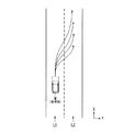
図4は、自車位置認識部140により走行車線L1に対する自車両Mの相対位置が認識される様子を示す図である。自車位置認識部140は、例えば、自車両Mの基準点(例えば重心)の走行車線中央CLからの乖離OS、および自車両Mの進行方向の走行車線中央CLを連ねた線に対してなす角度θを、走行車線L1に対する自車両Mの相対位置として認識する。なお、これに代えて、自車位置認識部140は、自車線L1の何れかの側端部に対する自車両Mの基準点の位置等を、走行車線に対する自車両Mの相対位置として認識してもよい。自車位置認識部140により認識される自車両Mの相対位置は、行動計画生成部144に提供される。
FIG. 4 is a diagram showing how the vehicle
外界認識部142は、ファインダ20、レーダ30、カメラ40等から入力される情報に基づいて、周辺車両の位置、および速度、加速度等の状態を認識する。周辺車両とは、例えば、自車両Mの周辺を走行する車両であって、自車両Mと同じ方向に走行する車両である。周辺車両の位置は、他車両の重心やコーナー等の代表点で表されてもよいし、他車両の輪郭で表現された領域で表されてもよい。周辺車両の「状態」とは、上記各種機器の情報に基づいて把握される、周辺車両の加速度、車線変更をしているか否か(あるいは車線変更をしようとしているか否か)を含んでもよい。また、外界認識部142は、周辺車両に加えて、ガードレールや電柱、駐車車両、歩行者その他の物体の位置を認識してもよい。
The external
行動計画生成部144は、自動運転のスタート地点、および/または自動運転の目的地を設定する。自動運転のスタート地点は、自車両Mの現在位置であってもよいし、自動運転を指示する操作がなされた地点でもよい。行動計画生成部144は、そのスタート地点と自動運転の目的地との間の区間において、行動計画を生成する。なお、これに限らず、行動計画生成部144は、任意の区間について行動計画を生成してもよい。
The action
行動計画は、例えば、順次実行される複数のイベントで構成される。イベントには、例えば、自車両Mを減速させる減速イベントや、自車両Mを加速させる加速イベント、走行車線を逸脱しないように自車両Mを走行させるレーンキープイベント、走行車線を変更させる車線変更イベント、自車両Mに前走車両を追い越させる追い越しイベント、分岐ポイントにおいて所望の車線に変更させたり、現在の走行車線を逸脱しないように自車両Mを走行させたりする分岐イベント、本線に合流するための合流車線において自車両Mを加減速させ、走行車線を変更させる合流イベント、自動運転の開始地点で手動運転モードから自動運転モードに移行させたり、自動運転の終了予定地点で自動運転モードから手動運転モードに移行させたりするハンドオーバイベント等が含まれる。行動計画生成部144は、目標車線決定部110により決定された目標車線が切り替わる箇所において、車線変更イベント、分岐イベント、または合流イベントを設定する。行動計画生成部144によって生成された行動計画を示す情報は、行動計画情報186として記憶部180に格納される。
The action plan is composed of, for example, a plurality of events that are sequentially executed. Examples of the event include a deceleration event for decelerating the host vehicle M, an acceleration event for accelerating the host vehicle M, a lane keeping event for driving the host vehicle M so as not to deviate from the traveling lane, and a lane change event for changing the traveling lane. In order to merge with the overtaking event in which the own vehicle M overtakes the preceding vehicle, the branch event in which the own vehicle M is driven so as not to deviate from the current traveling lane, or the main line Accelerates and decelerates the own vehicle M in the merging lane of the vehicle, a merging event that changes the driving lane, shifts from the manual driving mode to the automatic driving mode at the start point of the automatic driving, or manually from the automatic driving mode at the scheduled end point of the automatic driving. A handover event or the like for shifting to the operation mode is included. The action
図5は、ある区間について生成された行動計画の一例を示す図である。図5に示すように、行動計画生成部144は、目標車線情報184が示す目標車線上を自車両Mが走行するために必要な行動計画を生成する。なお、行動計画生成部144は、自車両Mの状況変化に応じて、目標車線情報184に拘わらず、動的に行動計画を変更してもよい。例えば、行動計画生成部144は、車両走行中に外界認識部142によって認識された周辺車両の速度が閾値を超えたり、自車線に隣接する車線を走行する周辺車両の移動方向が自車線方向に向いたりした場合に、自車両Mが走行予定の運転区間に設定されたイベントを変更する。例えば、レーンキープイベントの後に車線変更イベントが実行されるようにイベントが設定されている場合において、外界認識部142の認識結果によって当該レーンキープイベント中に車線変更先の車線後方から車両が閾値以上の速度で進行してきたことが判明した場合、行動計画生成部144は、レーンキープイベントの次のイベントを、車線変更イベントから減速イベントやレーンキープイベント等に変更してよい。この結果、車両制御システム100は、外界の状態に変化が生じた場合においても、安全に自車両Mを自動走行させることができる。
FIG. 5 is a diagram illustrating an example of an action plan generated for a certain section. As shown in FIG. 5, the action
図6は、軌道生成部146の構成の一例を示す図である。軌道生成部146は、例えば、走行態様決定部146Aと、軌道候補生成部146Bと、評価・選択部146Cとを備える。
FIG. 6 is a diagram illustrating an example of the configuration of the
走行態様決定部146Aは、例えば、レーンキープイベントを実施する際に、定速走行、追従走行、低速追従走行、減速走行、カーブ走行、障害物回避走行等のうち何れかの走行態様を決定する。例えば、走行態様決定部146Aは、自車両Mの前方に他車両が存在しない場合に、走行態様を定速走行に決定する。また、走行態様決定部146Aは、前走車両に対して追従走行するような場合に、走行態様を追従走行に決定する。また、走行態様決定部146Aは、渋滞場面等において、走行態様を低速追従走行に決定する。また、走行態様決定部146Aは、外界認識部142により前走車両の減速が認識された場合や、停車や駐車等のイベントを実施する場合に、走行態様を減速走行に決定する。また、走行態様決定部146Aは、外界認識部142により自車両Mがカーブ路に差し掛かったことが認識された場合に、走行態様をカーブ走行に決定する。また、走行態様決定部146Aは、外界認識部142により自車両Mの前方に障害物が認識された場合に、走行態様を障害物回避走行に決定する。
For example, when the lane keeping event is performed, the travel
軌道候補生成部146Bは、走行態様決定部146Aにより決定された走行態様に基づいて、軌道の候補を生成する。図7は、軌道候補生成部146Bにより生成される軌道の候補の一例を示す図である。図7は、自車両Mが車線L1から車線L2に車線変更する場合に生成される軌道の候補を示している。
The trajectory
軌道候補生成部146Bは、図7に示すような軌道を、例えば、将来の所定時間ごとに、自車両Mの基準位置(例えば重心や後輪軸中心)が到達すべき目標位置(軌道点K)の集まりとして決定する。図8は、軌道候補生成部146Bにより生成される軌道の候補を軌道点Kで表現した図である。軌道点Kの間隔が広いほど、自車両Mの速度は速くなり、軌道点Kの間隔が狭いほど、自車両Mの速度は遅くなる。従って、軌道候補生成部146Bは、加速したい場合には軌道点Kの間隔を徐々に広くし、減速したい場合は軌道点の間隔を徐々に狭くする。
The trajectory
このように、軌道点Kは速度成分を含むものであるため、軌道候補生成部146Bは、軌道点Kのそれぞれに対して目標速度を与える必要がある。目標速度は、走行態様決定部146Aにより決定された走行態様に応じて決定される。
Thus, since the trajectory point K includes a velocity component, the trajectory
ここで、車線変更(分岐を含む)を行う場合の目標速度の決定手法について説明する。軌道候補生成部146Bは、まず、車線変更ターゲット位置(或いは合流ターゲット位置)を設定する。車線変更ターゲット位置は、周辺車両との相対位置として設定されるものであり、「どの周辺車両の間に車線変更するか」を決定するものである。軌道候補生成部146Bは、車線変更ターゲット位置を基準として3台の周辺車両に着目し、車線変更を行う場合の目標速度を決定する。
Here, a method for determining a target speed when a lane change (including a branch) is performed will be described. The track
図9は、車線変更ターゲット位置TAを示す図である。図中、L1は自車線を表し、L2は隣接車線を表している。ここで、自車両Mと同じ車線で、自車両Mの直前を走行する周辺車両を前走車両mA、車線変更ターゲット位置TAの直前を走行する周辺車両を前方基準車両mB、車線変更ターゲット位置TAの直後を走行する周辺車両を後方基準車両mCと定義する。自車両Mは、車線変更ターゲット位置TAの側方まで移動するために加減速を行う必要があるが、この際に前走車両mAに追いついてしまうことを回避しなければならない。このため、軌道候補生成部146Bは、3台の周辺車両の将来の状態を予測し、各周辺車両と干渉しないように目標速度を決定する。
FIG. 9 is a diagram illustrating the lane change target position TA. In the figure, L1 represents the own lane and L2 represents the adjacent lane. Here, in the same lane as that of the own vehicle M, the preceding vehicle mA is set as the surrounding vehicle that runs immediately before the own vehicle M, the front reference vehicle mB, and the lane change target position TA is set as the surrounding vehicle that runs immediately before the lane changing target position TA. A surrounding vehicle traveling immediately after is defined as a rear reference vehicle mC. The host vehicle M needs to perform acceleration / deceleration in order to move to the side of the lane change target position TA. However, it is necessary to avoid catching up with the preceding vehicle mA at this time. For this reason, the trajectory
図10は、3台の周辺車両の速度を一定と仮定した場合の速度生成モデルを示す図である。図中、mA、mBおよびmCから延出する直線は、それぞれの周辺車両が定速走行したと仮定した場合の進行方向における変位を示している。自車両Mは、車線変更が完了するポイントCPにおいて、前方基準車両mBと後方基準車両mCとの間にあり、且つ、それ以前において前走車両mAよりも後ろにいなければならない。このような制約の下、軌道候補生成部146Bは、車線変更が完了するまでの目標速度の時系列パターンを、複数導出する。そして、目標速度の時系列パターンをスプライン曲線等のモデルに適用することで、上述した図7に示すような軌道の候補を複数導出する。なお、3台の周辺車両の運動パターンは、図9に示すような定速度に限らず、定加速度、定ジャーク(躍度)を前提として予測されてもよい。
FIG. 10 is a diagram showing a speed generation model when the speeds of the three surrounding vehicles are assumed to be constant. In the figure, straight lines extending from mA, mB, and mC indicate displacements in the traveling direction when it is assumed that the respective surrounding vehicles have traveled at a constant speed. The own vehicle M must be between the front reference vehicle mB and the rear reference vehicle mC at the point CP at which the lane change is completed, and must be behind the preceding vehicle mA before that. Under such restrictions, the track
評価・選択部146Cは、軌道候補生成部146Bにより生成された軌道の候補に対して、例えば、計画性と安全性の二つの観点で評価を行い、走行制御部160に出力する軌道を選択する。計画性の観点からは、例えば、既に生成されたプラン(例えば行動計画)に対する追従性が高く、軌道の全長が短い場合に軌道が高く評価される。例えば、右方向に車線変更することが望まれる場合に、一旦左方向に車線変更して戻るといった軌道は、低い評価となる。安全性の観点からは、例えば、それぞれの軌道点において、自車両Mと物体(周辺車両等)との距離が遠く、加減速度や操舵角の変化量等が小さいほど高く評価される。
The evaluation /
切替制御部150は、自動運転切替スイッチ87から入力される信号に基づいて自動運転モードと手動運転モードとを相互に切り替える。また、切替制御部150は、HMI70における運転操作系の構成に対する加減速または操舵を指示する操作に基づいて、自動運転モードから手動運転モードに切り替える。例えば、切替制御部150は、HMI70における運転操作系の構成から入力された信号の示す操作量が閾値を超えた状態が、基準時間以上継続した場合に、自動運転モードから手動運転モードに切り替える(オーバーライド)。なお、切替制御部150は、オーバーライドによる手動運転モードへの切り替えの後、所定時間の間、HMI70における運転操作系の構成に対する操作が検出されなかった場合に、自動運転モードに復帰させてもよい。また、切替制御部150は、例えば自動運転の終了予定地点で自動運転モードから手動運転モードに移行するハンドオーバ制御を行う場合に、車両乗員に対して事前にハンドオーバリクエストを通知するため、その旨の情報を、HMI制御部170に出力する。
The switching
走行制御部160は、軌道生成部146によって生成された軌道を、予定の時刻通りに自車両Mが通過するように、走行駆動力出力装置200、ステアリング装置210、およびブレーキ装置220を制御する。
The
HMI制御部170は、自動運転制御部120により得られる運転モードの情報に基づいてHMI70を制御する。なお、HMI制御部170、およびHMI70のうち表示装置82およびスピーカ83は、「報知部」の一例である。HMI制御部170およびHMI70は、自車両Mの自動運転のモードが自車両Mの走行環境に応じて複数のモードの何れかに遷移する場合に、モードが遷移するタイミングを予測し、予測したタイミングを表示装置82およびスピーカ83等を用いて報知する。例えば、HMI制御部170およびHMI70は、例えば、自動運転の度合が高い状態から低い状態に遷移するまでの継続時間を予測するが、自動運転の度合が低い状態から高い状態に遷移するまでの継続時間を予測してもよい。
The
例えば、HMI制御部170は、運転モードに基づいて、HMI70の非運転操作系やナビゲーション装置50等のインターフェース装置に対する車両乗員による操作の可否を制御する。また、HMI制御部170は、車両乗員に要求される周辺監視義務の度合が異なる自動運転のモードの変更が行われる場合やインターフェース装置の操作許容度が異なる自動運転モードに変更される場合に、インターフェース装置に所定の情報を出力させる。
For example, the
図11は、HMI制御部170の構成の一例を示す図である。また、図11に示すHMI制御部170は、予測継続時間算出部172と、インターフェース制御部174と、視線検出部176とを備える。
FIG. 11 is a diagram illustrating an example of the configuration of the
予測継続時間算出部172は、自車両Mの自動運転のモードが自車両Mの走行環境に応じて複数のモードの何れかに遷移する場合に、モードが遷移するタイミングを予測する。具体的には、予測継続時間算出部172は、自動運転制御部120により取得したモード情報が、情報の出力が必要な運転モードである場合に、自車両Mの現在の運転モードが継続される時間(モードの予測継続時間)を算出する。情報の出力が必要であるか否かの判定は、例えば、運転モードが第2モードから第1モードに変更され、周辺監視義務の度合が低下した場合またはインターフェース装置の操作許容度が増加した場合等があるが、これに限定されるものではない。
The prediction
モードの予測継続時間を予測する場合、予測継続時間算出部172は、車両センサ60から自車両Mの車速(走行速度)を取得するとともに、通信装置55を介して外部装置(例えば交通管理システム等の管理サーバ)等に対して交通情報の取得要求を行い、自車両Mが走行する目的地までの経路に関する交通情報を取得する。この場合、予測継続時間算出部172は、上述した自車両M内のGNSS受信機等により推定される自車両Mの位置情報を外部装置に送信し、位置情報に対応する周辺地域の交通情報を受信してよい。
When predicting the predicted duration of the mode, the predicted
次に、予測継続時間算出部172は、受信した交通情報と、自車両Mの車速とに基づいて、モードの予測継続時間を算出する。図12は、モードの予測継続時間の算出例を説明するための図である。予測継続時間算出部172は、例えば自車両Mの現在位置と、受信した交通情報から渋滞が解消されると予測される位置(渋滞解消予測位置)との距離を算出し(図12の例では、距離5km)、算出した距離を自車両Mの現在の車速で除算する。これにより、予測継続時間算出部172は、自車両Mが現在の位置から渋滞が解消されると予測される位置までの移動にかかる時間(図12に示す第1の時間)を算出する。
Next, the predicted
また、予測継続時間算出部172は、渋滞解消予測位置を基準として、その位置から自車両Mを所定の加速度により加速させて、第1モードから第2モードに切り替わる(またはTJPモードが解除される)所定の速度に至るまでの時間(図12に示す第2の時間)を算出する。第2の時間は、例えば自車両Mの現在の車速を基準に、渋滞解消予測位置から所定の加速度で加速させた場合に、第2モードに切り替わる所定の速度に至るまでの時間であり、自車両Mが図12に示す加速区間を移動する時間に相当する。次に、予測継続時間算出部172は、図12に示すように、上述した第1の時間と第2の時間とを加算してモードの予測継続時間を算出し、算出した予測継続時間をインターフェース制御部174に出力する。
Also, the predicted
なお、予測継続の算出方法は、これに限定されるものではなく、例えば上述した第1の時間を予測継続時間としてもよく、交通状態に応じて第1の時間と第2の時間との加算結果に調整時間を付加して予測継続時間としてもよい。また、予測継続時間算出部172は、上述した運転モードの予測継続時間の算出を一定時間ごとに行い、一定時間ごとに得られるモードの予測継続時間をインターフェース制御部174に出力する。一定時間ごとにモードの予測継続時間を予測することで、交通状況等の変化に応じた最新の予測継続時間を出力することができる。
Note that the calculation method for predictive continuation is not limited to this. For example, the above-described first time may be used as the predictive continuation time, and the first time and the second time are added according to the traffic state. Adjustment time may be added to the result to obtain the predicted duration. Further, the predicted
また、インターフェース制御部174は、自動運転制御部120が実施する自動運転のモードに応じて、自車両の車両乗員の操作を受け付けるとともに、情報を出力するHMI70の非運転操作系のインターフェース装置への操作を制限する。例えば、予測継続時間算出部172により予測されたモードの予測継続時間を、HMI70内の各インターフェース装置に出力する。インターフェース制御部174は、例えば自動運転モードが、自車両Mの周辺監視義務の度合が高い自動運転モードに変更されるタイミングまでの予測継続時間を示す情報をインターフェース装置に出力させる。
Further, the
例えば、インターフェース制御部174は、予測継続時間を示す情報をインターフェース装置に出力させることを、自車両Mの周辺監視義務の度合が高い自動運転モードに変更される前の自動運転モードの開始タイミングで開始してもよい。また、インターフェース制御部174は、自車両Mの周辺監視義務の度合が高い自動運転モードから自車両の周辺監視義務の度合が低い自動運転モードに変更されたタイミングで開始してもよい。
For example, the
図13は、インターフェース装置からの情報出力例を示す図である。図13の例では、上述した第1モードの一例を渋滞追従モード(TJPモード)とし、上述した第2モードの一例を渋滞追従モード外(TJP解除モード)とを用いて説明する。 FIG. 13 is a diagram illustrating an example of information output from the interface device. In the example of FIG. 13, an example of the first mode described above will be described as a traffic jam tracking mode (TJP mode), and an example of the second mode described above will be described using an outside of the traffic jam tracking mode (TJP release mode).
図13の例において、自車両Mが渋滞追従モード外である場合(図13に示す「(1)渋滞追従モード外」の場合)、自車両Mの車両乗員には、周辺監視義務が課せられているため、インターフェース装置に対する所定の操作が制限される。したがって、図13に示すように、ナビゲーション画面300は表示させることができるが、テレビ番組を表示する画面310は非表示となる。
In the example of FIG. 13, when the host vehicle M is out of the traffic jam tracking mode (in the case of “(1) traffic jam tracking mode out” shown in FIG. 13), the vehicle occupant of the host vehicle M is obliged to monitor the surroundings. Therefore, a predetermined operation on the interface device is limited. Therefore, as shown in FIG. 13, the
ここで、図13に示すように自車両Mの自動運転により、渋滞追従モード外から渋滞追従モードに移行した場合(図13に示す「(2)渋滞追従モード」の場合)、ナビゲーション画面320は、経路案内の画面が表示されるが、その場合に渋滞追従モードを開始する旨のメッセージ画面322を表示する。
Here, as shown in FIG. 13, when the vehicle M automatically shifts from the traffic jam tracking mode to the traffic jam tracking mode (in the case of “(2) traffic jam tracking mode” shown in FIG. 13), the
また、ナビゲーション画面320からメニュー画面330に推移した場合、「渋滞追従モードは操作制限が解除可能です。車両や交通の状況に応じて運転を行ってください」等のメッセージ画面332を表示するとともにOKボタン334を表示することで、車両乗員に注意喚起等を通知することができる。なお、メッセージの内容については、これに限定されるものではない。インターフェース制御部174は、車両乗員がOKボタン334を選択したことを受け付けることで、操作制限を解除し、DVD画面に遷移してナビゲーション装置50等を操作させることができる。
In addition, when the
また同様に、ナビゲーション画面320からDVD操作によりDVD画面340に推移した場合も、上述したメッセージ画面342とOKボタン344とを表示することで、車両乗員に注意喚起等を通知することができる。インターフェース制御部174は、車両乗員がOKボタン344を選択したことを受け付けることで、操作制限を解除し、DVD画面に遷移してナビゲーション装置50等を操作させることができる。
Similarly, when the
ここで、インターフェース制御部174は、遷移したDVD映像表示画面350において、渋滞追従モード中である旨を示す情報(モード情報)と、現在のモードの予測継続時間に関する情報を含むメッセージ352を表示させる。図13の例では、モードの予測継続時間が23分である場合に、メッセージ352として、「渋滞追従モード中 モード終了まで残り23分です。」等の情報をDVD映像に重畳して表示することができる。
Here, the
なお、メッセージ352を重畳表示することで、DVD映像の一部が隠れてしまう場合があるため、インターフェース制御部174は、DVD映像の表示領域とは重ならない異なる領域を設けて、その領域に表示させてもよく、メッセージ352を半透明にして表示してもよい。また、インターフェース制御部174は、メッセージ352を表示してから数秒経過後にメッセージを消去してもよい。メッセージ352に含まれる予測継続時間の情報は、一定時間ごとに更新して表示されてもよい。これにより、車両乗員は、モード変更により周辺監視義務の度合が増加するまでの予測時間を把握できるため、自動運転の切り替わりへの準備期間を得ることができるとともに、それまでの時間、安心してDVD映像を見ることができる。
Note that a portion of the DVD video may be hidden by displaying the
また、渋滞追従モードからのモード変更により、自車両に対する周辺監視義務が生じた場合(図13に示す「(3)渋滞追従モード外」の場合)に、メニュー画面330は、走行制限画面360に推移し、走行制限が行われる旨のメッセージ362を表示する。メッセージの一例としては、図13に示すように「渋滞追従モードを終了します。運転を再開してください。」等のメッセージが、車両乗員が自車両Mを運転する前(例えば、ハンドオーバへの準備を促すタイミング)で表示される。また、DVD映像表示画面350からの遷移においても同様にナビゲーション画面370が表示されると共に、同様のメッセージ372が車両乗員の状態に応じた所定のタイミングで表示される。メッセージ362、372は、所定時間だけ表示させてもよく、モードが切り替わるまで表示させてもよい。また、メッセージの内容については、上述した例に限定されるものではない。また、図13に示す各メッセージは、画面表示とともに音声を出力してもよく、また音声のみを出力してもよい。
In addition, when a change in the mode from the traffic jam tracking mode causes the surrounding vehicle to be monitored (in the case of “(3) traffic jam tracking mode out” shown in FIG. 13), the
図13に示すように、HMI70およびHMI制御部170の一部を含む報知部は、所定速度以下で前走車に追従して自動運転を行う渋滞追従走行モードの予測継続時間を報知する。例えば、報知部は、所定速度以下で前走車に追従して自動運転を行う渋滞追従走行モードから、所定の行動計画に従って通常の自動運転を行う通常走行モードに遷移するタイミング等を予測し、その予測した結果に基づいて渋滞追従走行モードの予測継続時間を算出し、報知することができる。また、報知部は、インターフェース装置の使用状態に基づいて、所定の情報の出力の有無または態様を変更する。これにより、車両乗員は、インターフェース装置等から運転モードの切り替えに対する適切な情報を取得することができる。上述したインターフェース装置による情報の出力により、自動運転の切り替わりタイミングを車両乗員に認識させることで、車両乗員に効率的な時間の使い方をさせることができる。
As shown in FIG. 13, the notification unit including a part of the
また、インターフェース制御部174は、自動運転制御部120から得られるモード情報に基づいて、HMI70またはナビゲーション装置50に関する操作の可否制御を行う。例えば、自車両Mが手動運転モードの場合、車両乗員は、HMI70の運転操作系(例えば、アクセルペダル71、ブレーキペダル74、シフトレバー76、およびステアリングホイール78等)を操作する。また、自動運転モードの第2モード、第3モード等である場合、車両乗員は、自車両Mの周辺監視義務が生じる。このような場合、車両乗員の運転以外の行動(操作等)により注意が散漫になること(ドライバーディストラクション)を防止するため、インターフェース制御部174は、HMI70の非運転操作系の一部または全部に対する操作を受け付けないように制御を行う。
In addition, the
また、インターフェース制御部174は、運転モードが自動運転の第2モードから第1モードに遷移した場合、ドライバーディストラクション規制を緩和し、操作を受け付けていなかった非運転操作系に対する車両乗員の操作を受け付ける制御を行う。例えば、インターフェース制御部174は、自動運転制御部120から得られるモード情報と、記憶部180に記憶されたモード別操作可否情報188とに基づいて、HMI70またはナビゲーション装置50に関する操作の可否を判定する。
In addition, when the driving mode transitions from the second mode to the first mode of the automatic driving, the
図14は、モード別操作可否情報188の一例を示す図である。図14に示すモード別操作可否情報188は、運転モードの項目として「手動運転モード」、「自動運転モード」とを有する。また、「自動運転モード」として、上述した「第1モード」、「第2モード」、および「第3モード」等を有する。また、モード別操作可否情報188は、非運転操作系の項目として、ナビゲーション装置50に対する操作である「ナビゲーション操作」、コンテンツ再生装置85に対する操作である「コンテンツ再生操作」、表示装置82に対する操作である「インストルメントパネル操作」等を有する。図14に示すモード別操作可否情報188の例では、上述した運転モードごとに非運転操作系に対する車両乗員の操作の可否が設定されているが、対象のインターフェース装置は、これに限定されるものではない。
FIG. 14 is a diagram illustrating an example of the mode-specific
インターフェース制御部174は、自動運転制御部120から取得したモード情報(運転モード)に基づいてモード別操作可否情報188を参照することで、使用が許可されるインターフェース装置(各操作系)と、使用が許可されないインターフェース装置とを判定する。また、インターフェース制御部174は、判定結果に基づいて、非運転操作系のインターフェース装置に対する車両乗員からの操作の受け付けの可否を制御する。
The
また、インターフェース制御部174は、視線検出部176により得られる車両乗員の視線検出結果に基づいて、情報を出力する対象のインターフェース装置(HMI70)を選択して表示させてもよい。図15は、自車両Mの車両乗員の視線検出の内容を説明するための図である。
Further, the
図15の例において、自車両M内に車両乗員Pの頭部(顔)を撮像できる車室内カメラ95が設けられている。なお、図15の例では、車両乗員Pがシート88に着座してステアリングホイール78を把持し、手動運転を行える状態を示している。また、図15の例では、HMI70のインターフェース装置の一例として、ナビゲーション装置50と、表示装置82とを示している。
In the example of FIG. 15, a
視線検出部176は、例えばHMI70の車室内カメラ95により撮像された画像の輝度および形状等の特徴情報に基づいて、車両乗員の目頭の位置と、虹彩の位置とを検出する。また、視線検出部176は、検出した目頭と虹彩との位置関係から、視線方向を検出する。なお、視線検出手法については、上述した例に限定されるものではない。また、視線検出部176は、検出した車両乗員Pの視線方向にあるインターフェース装置を推定する。
The line-of-
例えば、車室内カメラ95の撮像範囲(画角)が固定である場合、視線検出部176は、撮像画像上におけるナビゲーション装置50や表示装置82等のインターフェース装置のそれぞれの画像上の位置が推定される。したがって、画像上における視線方向先の位置情報に基づいて、車両乗員Pが見ているインターフェース装置と推定することができる。
For example, when the imaging range (angle of view) of the
例えば、図15の例において、車室内カメラ95により撮像された撮像画像から車両乗員Pの視線方向を検出し、検出した視線方向が矢印aである場合、視線検出部176は、車両乗員Pがナビゲーション装置50を見ていると推定する。また、視線方向が矢印bである場合、視線検出部176は、例えばインストルメントパネル等の表示装置82を見ているものと推定する。視線検出部176は、推定された視線方向にあるインターフェース装置の情報をインターフェース制御部174に出力する。
For example, in the example of FIG. 15, when the line-of-sight direction of the vehicle occupant P is detected from the captured image captured by the
インターフェース制御部174は、視線検出部176から得られる車両乗員Pの視線方向にあるインターフェース装置に上述した自動運転の現在のモードの継続時間を含む情報を出力することができる。これにより、全てのインターフェース装置に表示させるよりも処理負担を軽減することができるとともに、車両乗員Pに対して自動運転の運転モードの変更に関する情報(モードの予測継続時間)等を、より確実に認識させることができる。
The
<処理フロー>
以下、本実施形態に係る車両制御システム100よる処理の流れについて説明する。なお、以下の説明では、車両制御システム100のおける各種処理のうち、主にHMI制御部170により実施される自動運転のモード変更に伴う情報出力に関するHMI制御処理の流れについて説明する。
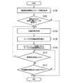
<Processing flow>
Hereinafter, the flow of processing by the
[第1の実施例]
図16は、HMI制御処理の第1の実施例を示すフローチャートである。図16の例において、HMI制御部170は、自動運転制御部120よりモード情報を取得する(ステップS100)。次に、予測継続時間算出部172は、取得したモード情報に含まれる運転モードが、現在の運転モードから変更されることにより、情報の出力が必要な変更か否かを判定する(ステップS102)。情報の出力が必要な運転モードとは、例えば車両乗員の周辺監視義務の度合が低下する運転モードまたはインターフェース装置の操作許容度が増加する運転モードであり、一例として、第2モードから第1モードへの変更、TJP解除モードからTJPモードへの変更等が相当するが、これに限定されるものではない。
[First embodiment]
FIG. 16 is a flowchart showing a first embodiment of the HMI control process. In the example of FIG. 16, the
情報の出力が必要である場合、予測継続時間算出部172は、交通情報を取得し(ステップS104)、モードの予測継続時間を算出する(ステップS106)。なお、モードの予測継続時間の算出処理の詳細については後述する。
When the output of information is necessary, the predicted
次に、インターフェース制御部174は、自車両M内のHMI70の各インターフェース装置に、算出されたモードの予測継続時間を出力する(ステップS108)。次に、インターフェース制御部174は、モードの予測継続時間を出力してから一定時間(例えば、1〜3分)が経過したか否かを判定する(ステップS110)。一定時間が経過した場合、ステップS104の処理に戻り、最新の交通情報を取得して予測継続時間を算出する。これにより、一定時間ごとに最新の予測継続時間を車両乗員に表示することができる。
Next, the
また、一定時間が経過していない場合、インターフェース制御部174は、予測継続時間の出力を終了するか否かを判定する(ステップS112)。ステップS112の処理では、インターフェース制御部174は、自車両Mの運転モードが切り替わる制御が実施される場合や制御車両乗員から終了指示があった場合に予測継続時間の出力を終了させるが、これに限定されるものではない。
If the predetermined time has not elapsed, the
予測継続時間の出力終了しない場合、インターフェース制御部174は、ステップS110の処理に戻る。また、予測継続時間の出力を終了する場合、インターフェース制御部174は、本フローチャートを終了する。上述したステップS102の処理において、情報の出力が必要な運転モードの変更でない場合、インターフェース制御部174は、本フローチャートを終了する。
If the output of the predicted duration time is not finished, the
[モードの予測継続時間の算出処理(ステップS106)]
次に、上述したステップS106におけるモードの予測継続時間の算出処理の一例について、フローチャートを用いて説明する。図17は、モードの予測継続時間の算出処理の一例を示すフローチャートである。図17の例において、予測継続時間算出部172は、自車両Mの現在位置から渋滞が解消されると予測される位置までの距離を取得する(ステップS200)。ステップS200の処理では、例えばナビゲーション装置50により車両乗員が設定した目的値までの経路において、GNSS受信機から推定される自車両Mの現在位置と、その経路に関する交通情報から得られる渋滞が解消されると予測される位置との経路上の距離を取得する。渋滞が解消されると予測される位置とは、例えば交通情報に「○○ジャンクションで渋滞」、「△△料金所で渋滞」等の渋滞情報が含まれていれば、その○○ジャンクションや△△料金所の位置であり、この位置情報は、例えば高精度地図情報182から取得することができる。
[Calculation process of predicted duration of mode (step S106)]
Next, an example of the calculation processing of the predicted duration time of the mode in step S106 described above will be described using a flowchart. FIG. 17 is a flowchart illustrating an example of processing for calculating a predicted duration of mode. In the example of FIG. 17, the predicted
次に、予測継続時間算出部172は、取得した距離と自車両Mの車速とから、渋滞が解消されるまでの時間(第1の時間)を算出する(ステップS202)。なお、現時点で自車両Mが渋滞等で停止している場合(車速0km/hの場合)、それまでの所定時間(例えば、3分〜30分程度)における平均車速を用いて、上述した第1の時間を算出してもよい。第1の時間は、例えば距離を車速で除算することで取得することができる。
Next, the predicted
次に、予測継続時間算出部172は、現時点での車速(または上述した平均車速)に基づき、渋滞が解消されると予測される位置からの加速により運転モードが切り替わる速度に至るまでの時間(第2の時間)を算出する(ステップS204)。なお、上記の加速は、予め設定された単位時間あたりの加速度に基づいて加速するが、これに限定されるものではなく、徐々に加速度を増加するように設定されていてもよい。次に、予測継続時間算出部172は、上述した第1の時間と第2の時間とを加算した時間をモードの予測継続時間として算出する(ステップS206)。
Next, the predicted
[第2の実施例]
図18は、HMI制御処理の第2の実施例を示すフローチャートである。図18の例において、ステップS300〜S306の処理は、上述した第1の実施例におけるステップS100〜S106の処理と同様であるため、ここでの具体的な説明は省略する。
[Second Embodiment]
FIG. 18 is a flowchart showing a second embodiment of the HMI control process. In the example of FIG. 18, the processing of steps S300 to S306 is the same as the processing of steps S100 to S106 in the first embodiment described above, and a specific description thereof will be omitted here.
ステップS306の処理で、モードの予測継続時間を算出後、視線検出部176は、車室内カメラ95等から撮影される画像により車両乗員の視線を検出し(ステップS308)、検出された視線方向にあるHMI70のインターフェース装置を特定する(ステップS310)。
After calculating the predicted duration of the mode in the process of step S306, the line-of-
次に、インターフェース制御部174は、視線方向にある特定されたインターフェース装置に、算出されたモードの予測継続時間を出力する(ステップS312)。次に、インターフェース制御部174は、モードの予測継続時間を出力してから一定時間(例えば、1〜3分)が経過したか否かを判定する(ステップS314)。一定時間が経過した場合、ステップS304の処理に戻り、最新の交通情報を取得して予測継続時間を算出するとともに、その時点での車両乗員の視線方向を検出し、検出した視線方向にあるインターフェース装置を特定する。これにより、一定時間ごとに最新の予測継続時間を表示することができ、更に、車両乗員の視線方向にあるインターフェース装置に表示されるため、車両乗員は、より確実にモードの予測継続時間を把握することができる。
Next, the
また、一定時間が経過していない場合、インターフェース制御部174は、予測継続時間の出力を終了するか否かを判定する(ステップS316)。ステップS316の処理では、インターフェース制御部174は、自車両Mの運転モードが切り替わる制御が実施される場合や制御車両乗員から終了指示があった場合に予測継続時間の出力を終了させるが、これに限定されるものではない。
If the predetermined time has not elapsed, the
また、予測継続時間の出力終了しない場合、インターフェース制御部174は、ステップS314の処理に戻る。また、予測継続時間の出力を終了する場合、インターフェース制御部174は、本フローチャートを終了する。上述したステップS302の処理において、情報の出力が必要な運転モードの変更でない場合、インターフェース制御部174は、本フローチャートを終了する。なお、図16、図18に示すHMI制御処理は、自動運転制御部120よりモード情報を取得した時点で実行してもよく、一定の時間間隔で実施してもよい。また、実施形態としては、上述した各実施例の一部または全部を組み合わせてもよい。
If the output of the predicted duration time is not finished, the
上述した実施形態によれば、車両制御システム100は、自動運転モードが、自車両の周辺監視義務の度合が高い自動運転モードに変更されるタイミングまたはインターフェース装置の操作許容度が低い自動運転モードに変更されるタイミングまでの予測継続時間を示す情報をインターフェース装置に出力させることで、自動運転の切り替わりタイミングを車両乗員に認識させることができ、車両乗員に効率的な時間の使い方をさせることができる。また、モードが変更されるタイミングまでの予測継続時間をインターフェース装置に出力させることで、自車両乗員は、自動運転モードの状態を把握できるため、自動運転における不安を軽減することができる。
According to the above-described embodiment, the
以上、本発明を実施するための形態について実施形態を用いて説明したが、本発明はこうした実施形態に何等限定されるものではなく、本発明の要旨を逸脱しない範囲内において種々の変形及び置換を加えることができる。 As mentioned above, although the form for implementing this invention was demonstrated using embodiment, this invention is not limited to such embodiment at all, In the range which does not deviate from the summary of this invention, various deformation | transformation and substitution Can be added.
20…ファインダ、30…レーダ、40…カメラ、DD…検知デバイス、50…ナビゲーション装置、55…通信装置、60…車両センサ、70…HMI、100…車両制御システム、110…目標車線決定部、120…自動運転制御部、130…自動運転モード制御部、140…自車位置認識部、142…外界認識部、144…行動計画生成部、146…軌道生成部、146A…走行態様決定部、146B…軌道候補生成部、146C…評価・選択部、150…切替制御部、160…走行制御部、170…HMI制御部、172…予測継続時間算出部、174…インターフェース制御部、176…視線検出部、180…記憶部、200…走行駆動力出力装置、210…ステアリング装置、220…ブレーキ装置、M…自車両 DESCRIPTION OF SYMBOLS 20 ... Finder, 30 ... Radar, 40 ... Camera, DD ... Detection device, 50 ... Navigation apparatus, 55 ... Communication apparatus, 60 ... Vehicle sensor, 70 ... HMI, 100 ... Vehicle control system, 110 ... Target lane determination part, 120 ... automatic driving control unit, 130 ... automatic driving mode control unit, 140 ... own vehicle position recognition unit, 142 ... external environment recognition unit, 144 ... action plan generation unit, 146 ... track generation unit, 146A ... running mode determination unit, 146B ... Track candidate generation unit, 146C ... evaluation / selection unit, 150 ... switch control unit, 160 ... running control unit, 170 ... HMI control unit, 172 ... predicted duration calculation unit, 174 ... interface control unit, 176 ... line of sight detection unit, 180: storage unit, 200: driving force output device, 210: steering device, 220: brake device, M: own vehicle
Claims (12)
前記自動運転のモードが前記自車両の走行環境に応じて前記複数のモードの何れかに遷移する場合に、前記モードが遷移するタイミングを予測し、予測したタイミングを報知する報知部と、
を備える車両制御システム。 An automatic driving control unit that automatically controls at least one of acceleration / deceleration and steering of the own vehicle, and performs automatic driving control in any of a plurality of modes having different degrees of automatic driving; and
When the mode of the automatic driving transitions to any one of the plurality of modes according to the traveling environment of the host vehicle, a notification unit that predicts a timing at which the mode transitions and notifies the predicted timing;
A vehicle control system comprising:
前記自動運転の度合が高い状態から低い状態に遷移するまでの継続時間を予測する、
請求項1に記載の車両制御システム。 The notification unit
Predicting the duration until the degree of automatic driving transitions from a high state to a low state,
The vehicle control system according to claim 1.
前記自車両の現在の自動運転のモードから、前記自動運転の度合が高い自動運転のモードに変更されるタイミングまでの予測継続時間を報知する、
請求項1または2に記載の車両制御システム。 The notification unit
Informing the predicted duration from the current automatic driving mode of the host vehicle to the timing of changing to the automatic driving mode in which the degree of the automatic driving is high,
The vehicle control system according to claim 1 or 2.
前記モードが遷移するタイミングを報知することを、前記自動運転の度合が高い自動運転のモードに変更される前のモードの開始タイミングで開始する、
請求項1から3のうち、何れか1項に記載の車両制御システム。 The notification unit
Informing the timing of the transition of the mode is started at the start timing of the mode before being changed to the mode of automatic driving where the degree of the automatic driving is high,
The vehicle control system according to any one of claims 1 to 3.
前記モードが遷移するタイミングを報知することを、前記自動運転の度合が高い自動運転のモードから前記自動運転の度合が低い自動運転のモードに変更されたタイミングで開始する、
請求項1から4のうち、何れか1項に記載の車両制御システム。 The notification unit
Informing the timing of the transition of the mode is started at the timing when the mode of the automatic driving with a high degree of automatic driving is changed to the mode of the automatic driving with a low degree of automatic driving,
The vehicle control system according to any one of claims 1 to 4.
所定速度以下で前走車に追従して自動運転を行う渋滞追従走行モードの予測継続時間を報知する、
請求項1から5のうち、何れか1項に記載の車両制御システム。 The notification unit
Notify the predicted duration of traffic following mode in which automatic driving is performed following the preceding vehicle at a predetermined speed or less,
The vehicle control system according to any one of claims 1 to 5.
前記自車両の現在位置と、前記自車両が走行する目的地までの経路に関する交通情報とに基づいて、前記予測継続時間を算出する予測継続時間算出部を備え、
前記予測継続時間算出部により算出された予測継続時間を報知する、
請求項3に記載の車両制御システム。 The notification unit
A predicted duration calculation unit that calculates the predicted duration based on the current position of the host vehicle and traffic information related to a route to the destination on which the host vehicle travels;
Informing the predicted duration calculated by the predicted duration calculator,
The vehicle control system according to claim 3.
一定時間ごとに、前記予測継続時間を算出する、
請求項7に記載の車両制御システム。 The predicted duration calculation unit
Calculating the predicted duration at regular intervals;
The vehicle control system according to claim 7.
前記自車両の現在位置と、前記交通情報から得られる渋滞が解消されると予測される位置とに基づいて、前記自車両が走行する経路上の距離を算出し、算出した距離と、前記自車両の車速とに基づいて第1の時間を算出するとともに、
前記交通情報から得られる渋滞が解消されると予測される位置から所定の加速度で前記自車両を加速させて所定の速度に至るまでの第2の時間を算出し、
算出した前記第1の時間と前記第2の時間とに基づいて前記予測継続時間を算出する、
請求項7または8に記載の車両制御システム。 The predicted duration calculation unit
Based on the current position of the host vehicle and the position where the traffic congestion obtained from the traffic information is predicted to be resolved, a distance on the route on which the host vehicle travels is calculated, the calculated distance, Calculating the first time based on the vehicle speed of the vehicle,
Calculating a second time from accelerating the host vehicle at a predetermined acceleration to a predetermined speed from a position where it is predicted that the traffic congestion obtained from the traffic information will be eliminated;
Calculating the predicted duration based on the calculated first time and the second time;
The vehicle control system according to claim 7 or 8.
前記報知部は、
前記視線検出部により検出された前記自車両の乗員の視線方向にあるインターフェース装置に前記モードが遷移するタイミングを報知する、
請求項1から9のうち、何れか1項に記載の車両制御システム。 A line-of-sight detection unit for detecting a line-of-sight direction of a passenger in the vehicle,
The notification unit
Informing the interface device in the line-of-sight direction of the occupant of the host vehicle detected by the line-of-sight detection unit of the timing at which the mode transitions,
The vehicle control system according to any one of claims 1 to 9.
自車両の加減速および操舵のうち少なくとも一方を自動的に制御するとともに、自動運転の度合が異なる複数のモードの何れかで自動運転制御を行い、
前記自動運転のモードが前記自車両の走行環境に応じて前記複数のモードの何れかに遷移する場合に、前記モードが遷移するタイミングを予測し、予測したタイミングを報知部に報知させる、
車両制御方法。 In-vehicle computer
While automatically controlling at least one of acceleration / deceleration and steering of the own vehicle, automatic driving control is performed in any of a plurality of modes having different degrees of automatic driving,
When the automatic driving mode transitions to any one of the plurality of modes according to the traveling environment of the host vehicle, the timing at which the mode transitions is predicted, and the predicted timing is notified to the notification unit.
Vehicle control method.
自車両の加減速および操舵のうち少なくとも一方を自動的に制御するとともに、自動運転の度合が異なる複数のモードの何れかで自動運転制御を行い、
前記自動運転のモードが前記自車両の走行環境に応じて前記複数のモードの何れかに遷移する場合に、前記モードが遷移するタイミングを予測し、予測したタイミングを報知部に報知させる、
処理を実行させるための車両制御プログラム。 On-board computer
While automatically controlling at least one of acceleration / deceleration and steering of the own vehicle, automatic driving control is performed in any of a plurality of modes having different degrees of automatic driving,
When the automatic driving mode transitions to any one of the plurality of modes according to the traveling environment of the host vehicle, the timing at which the mode transitions is predicted, and the predicted timing is notified to the notification unit.
A vehicle control program for executing processing.
Priority Applications (2)
| Application Number | Priority Date | Filing Date | Title |
|---|---|---|---|
| JP2016052980A JP6652417B2 (en) | 2016-03-16 | 2016-03-16 | Vehicle control system, vehicle control method, and vehicle control program |
| US15/460,859 US10427686B2 (en) | 2016-03-16 | 2017-03-16 | Vehicle control system, vehicle control method, and vehicle control program |
Applications Claiming Priority (1)
| Application Number | Priority Date | Filing Date | Title |
|---|---|---|---|
| JP2016052980A JP6652417B2 (en) | 2016-03-16 | 2016-03-16 | Vehicle control system, vehicle control method, and vehicle control program |
Publications (2)
| Publication Number | Publication Date |
|---|---|
| JP2017165289A true JP2017165289A (en) | 2017-09-21 |
| JP6652417B2 JP6652417B2 (en) | 2020-02-26 |
Family
ID=59855223
Family Applications (1)
| Application Number | Title | Priority Date | Filing Date |
|---|---|---|---|
| JP2016052980A Active JP6652417B2 (en) | 2016-03-16 | 2016-03-16 | Vehicle control system, vehicle control method, and vehicle control program |
Country Status (2)
| Country | Link |
|---|---|
| US (1) | US10427686B2 (en) |
| JP (1) | JP6652417B2 (en) |
Cited By (16)
| Publication number | Priority date | Publication date | Assignee | Title |
|---|---|---|---|---|
| JP2019159828A (en) * | 2018-03-13 | 2019-09-19 | 本田技研工業株式会社 | Vehicle control device, vehicle control method, and program |
| JP2019156356A (en) * | 2018-03-16 | 2019-09-19 | 本田技研工業株式会社 | Vehicular control device and vehicle |
| JP2019196154A (en) * | 2018-05-11 | 2019-11-14 | トヨタ自動車株式会社 | Vehicle control system |
| CN111149142A (en) * | 2017-09-28 | 2020-05-12 | 株式会社电装 | Control target vehicle setting device, control target vehicle setting system, and control target vehicle setting method |
| JP2020097380A (en) * | 2018-12-19 | 2020-06-25 | トヨタ自動車株式会社 | Automatic driving system |
| JP2020158008A (en) * | 2019-03-27 | 2020-10-01 | 株式会社Subaru | Automatic driving system |
| JP2021112936A (en) * | 2020-01-16 | 2021-08-05 | 本田技研工業株式会社 | Vehicle and control device for the same |
| WO2021199964A1 (en) * | 2020-03-31 | 2021-10-07 | 株式会社デンソー | Presentation control device, presentation control program, automated driving control system, and automated driving control program |
| JP2021160708A (en) * | 2020-03-31 | 2021-10-11 | 株式会社デンソー | Presentation control device, presentation control program, automatic travel control system and automatic travel control program |
| JP2022000376A (en) * | 2020-09-23 | 2022-01-04 | 阿波▲羅▼智▲聯▼(北京)科技有限公司 | Automatic drive function control method, device, electronic apparatus and storage medium |
| WO2022030269A1 (en) * | 2020-08-07 | 2022-02-10 | 株式会社デンソー | Vehicular display control device, vehicular display control system, and vehicular display control method |
| DE102021126348A1 (en) | 2020-10-19 | 2022-04-21 | Toyota Jidosha Kabushiki Kaisha | NOTIFICATION DEVICE FOR A DRIVER |
| WO2022163227A1 (en) * | 2021-01-27 | 2022-08-04 | 株式会社デンソー | Autonomous driving control device, autonomous driving control program, presentation control device, and presentation control program |
| JP2023033411A (en) * | 2019-07-05 | 2023-03-10 | 本田技研工業株式会社 | Control system of vehicle, control method of vehicle and program |
| JP7372367B2 (en) | 2022-02-07 | 2023-10-31 | 本田技研工業株式会社 | Vehicle and its control device and control method |
| JP7380418B2 (en) | 2020-05-22 | 2023-11-15 | 株式会社デンソー | Driving assistance devices and programs |
Families Citing this family (15)
| Publication number | Priority date | Publication date | Assignee | Title |
|---|---|---|---|---|
| US10220851B2 (en) * | 2016-12-14 | 2019-03-05 | Ford Global Technologies, Llc | Infrastructure-centric vehicle mode selection |
| JP2019048524A (en) * | 2017-09-08 | 2019-03-28 | スタンレー電気株式会社 | Device for controlling vehicle headlight |
| US11580859B1 (en) * | 2017-09-28 | 2023-02-14 | Apple Inc. | Vehicle lane change |
| JP6580115B2 (en) * | 2017-12-18 | 2019-09-25 | 本田技研工業株式会社 | Driving control device for autonomous driving vehicle |
| US11511735B2 (en) * | 2017-12-26 | 2022-11-29 | Sony Corporation | Signal processing apparatus and signal processing method |
| US11237554B2 (en) * | 2018-03-08 | 2022-02-01 | Steering Solutions Ip Holding Corporation | Driver readiness assessment system and method for vehicle |
| JP7087623B2 (en) * | 2018-04-19 | 2022-06-21 | トヨタ自動車株式会社 | Vehicle control unit |
| DE102018206425A1 (en) * | 2018-04-25 | 2019-10-31 | Bayerische Motoren Werke Aktiengesellschaft | Activation of a driving function for automated driving with longitudinal and lateral guidance via another driving function for automated driving with a low degree of automation |
| JP7055759B2 (en) * | 2019-01-24 | 2022-04-18 | 本田技研工業株式会社 | Vehicle control unit |
| DE102019209707B4 (en) * | 2019-07-02 | 2022-05-19 | Volkswagen Aktiengesellschaft | Method of operating a self-driving vehicle |
| JP7078909B2 (en) * | 2019-12-19 | 2022-06-01 | トヨタ自動車株式会社 | Vehicle control device and computer program for vehicle control |
| US11699205B1 (en) * | 2020-05-20 | 2023-07-11 | State Farm Mutual Automobile Insurance Company | Providing a GUI to enable analysis of time-synchronized data sets pertaining to a road segment |
| US11954315B1 (en) * | 2020-11-19 | 2024-04-09 | State Farm Mutual Automobile Insurance Company | Systems and methods for dynamically creating and adjusting scene models |
| CN113183965B (en) * | 2021-05-06 | 2022-04-22 | 恒大恒驰新能源汽车研究院(上海)有限公司 | Method, device and system for adjusting driving mode |
| EP4342757A1 (en) * | 2022-09-22 | 2024-03-27 | TuSimple, Inc. | Controlling driving modes and operations for autonomous vehicles |
Citations (5)
| Publication number | Priority date | Publication date | Assignee | Title |
|---|---|---|---|---|
| JP2010000949A (en) * | 2008-06-20 | 2010-01-07 | Toyota Motor Corp | Driving support device |
| JP2013156927A (en) * | 2012-01-31 | 2013-08-15 | Denso Corp | Reminder device and program |
| JP2015017944A (en) * | 2013-07-12 | 2015-01-29 | 株式会社デンソー | Automatic operation support device |
| WO2015162764A1 (en) * | 2014-04-24 | 2015-10-29 | 三菱電機株式会社 | Vehicle-mounted information device and function limiting method for vehicle-mounted information device |
| JP2015230573A (en) * | 2014-06-05 | 2015-12-21 | アルパイン株式会社 | Vehicle driving assistance device, method, and program |
Family Cites Families (7)
| Publication number | Priority date | Publication date | Assignee | Title |
|---|---|---|---|---|
| DE19743024A1 (en) * | 1997-09-29 | 1999-04-08 | Daimler Chrysler Ag | Road vehicle with automatic guidance and communication system |
| DE102005050277A1 (en) * | 2005-10-20 | 2007-04-26 | Robert Bosch Gmbh | Distance and speed controller with jam detection |
| US7606662B2 (en) * | 2006-07-31 | 2009-10-20 | Nissan Technical Center North America, Inc. | Traffic navigation system |
| DE102013012777A1 (en) * | 2013-07-31 | 2015-02-05 | Valeo Schalter Und Sensoren Gmbh | Method for using a communication terminal in a motor vehicle when activated autopilot and motor vehicle |
| JP6349833B2 (en) | 2014-03-25 | 2018-07-04 | 日産自動車株式会社 | Information display device |
| US10067561B2 (en) * | 2014-09-22 | 2018-09-04 | Facebook, Inc. | Display visibility based on eye convergence |
| WO2016109482A1 (en) * | 2014-12-29 | 2016-07-07 | Robert Bosch Gmbh | Drive state indicator for an autonomous vehicle |
-
2016
- 2016-03-16 JP JP2016052980A patent/JP6652417B2/en active Active
-
2017
- 2017-03-16 US US15/460,859 patent/US10427686B2/en active Active
Patent Citations (5)
| Publication number | Priority date | Publication date | Assignee | Title |
|---|---|---|---|---|
| JP2010000949A (en) * | 2008-06-20 | 2010-01-07 | Toyota Motor Corp | Driving support device |
| JP2013156927A (en) * | 2012-01-31 | 2013-08-15 | Denso Corp | Reminder device and program |
| JP2015017944A (en) * | 2013-07-12 | 2015-01-29 | 株式会社デンソー | Automatic operation support device |
| WO2015162764A1 (en) * | 2014-04-24 | 2015-10-29 | 三菱電機株式会社 | Vehicle-mounted information device and function limiting method for vehicle-mounted information device |
| JP2015230573A (en) * | 2014-06-05 | 2015-12-21 | アルパイン株式会社 | Vehicle driving assistance device, method, and program |
Cited By (31)
| Publication number | Priority date | Publication date | Assignee | Title |
|---|---|---|---|---|
| CN111149142A (en) * | 2017-09-28 | 2020-05-12 | 株式会社电装 | Control target vehicle setting device, control target vehicle setting system, and control target vehicle setting method |
| JP7071173B2 (en) | 2018-03-13 | 2022-05-18 | 本田技研工業株式会社 | Vehicle control devices, vehicle control methods, and programs |
| JP2019159828A (en) * | 2018-03-13 | 2019-09-19 | 本田技研工業株式会社 | Vehicle control device, vehicle control method, and program |
| JP7055043B2 (en) | 2018-03-16 | 2022-04-15 | 本田技研工業株式会社 | Vehicle control device and vehicle |
| JP2019156356A (en) * | 2018-03-16 | 2019-09-19 | 本田技研工業株式会社 | Vehicular control device and vehicle |
| CN110281931A (en) * | 2018-03-16 | 2019-09-27 | 本田技研工业株式会社 | Vehicle console device and vehicle |
| CN110281931B (en) * | 2018-03-16 | 2022-07-26 | 本田技研工业株式会社 | Vehicle control device and vehicle |
| JP2019196154A (en) * | 2018-05-11 | 2019-11-14 | トヨタ自動車株式会社 | Vehicle control system |
| JP7293635B2 (en) | 2018-12-19 | 2023-06-20 | トヨタ自動車株式会社 | Autonomous driving system |
| US11921501B2 (en) | 2018-12-19 | 2024-03-05 | Toyota Jidosha Kabushiki Kaisha | Automatic driving system |
| JP2021181308A (en) * | 2018-12-19 | 2021-11-25 | トヨタ自動車株式会社 | Automatic driving system |
| JP2020097380A (en) * | 2018-12-19 | 2020-06-25 | トヨタ自動車株式会社 | Automatic driving system |
| JP7287419B2 (en) | 2018-12-19 | 2023-06-06 | トヨタ自動車株式会社 | Autonomous driving system |
| JP7288326B2 (en) | 2019-03-27 | 2023-06-07 | 株式会社Subaru | Autonomous driving system |
| JP2020158008A (en) * | 2019-03-27 | 2020-10-01 | 株式会社Subaru | Automatic driving system |
| US11858527B2 (en) | 2019-07-05 | 2024-01-02 | Honda Motor Co., Ltd. | Control system for vehicle and control method for vehicle |
| JP2023033411A (en) * | 2019-07-05 | 2023-03-10 | 本田技研工業株式会社 | Control system of vehicle, control method of vehicle and program |
| JP7445028B2 (en) | 2019-07-05 | 2024-03-06 | 本田技研工業株式会社 | Vehicle control system, vehicle control method, and program |
| JP2021112936A (en) * | 2020-01-16 | 2021-08-05 | 本田技研工業株式会社 | Vehicle and control device for the same |
| US11654955B2 (en) | 2020-01-16 | 2023-05-23 | Honda Motor Co., Ltd. | Vehicle and control apparatus of vehicle |
| JP7363833B2 (en) | 2020-03-31 | 2023-10-18 | 株式会社デンソー | Presentation control device, presentation control program, automatic travel control system, and automatic travel control program |
| JP2021160708A (en) * | 2020-03-31 | 2021-10-11 | 株式会社デンソー | Presentation control device, presentation control program, automatic travel control system and automatic travel control program |
| WO2021199964A1 (en) * | 2020-03-31 | 2021-10-07 | 株式会社デンソー | Presentation control device, presentation control program, automated driving control system, and automated driving control program |
| JP7380418B2 (en) | 2020-05-22 | 2023-11-15 | 株式会社デンソー | Driving assistance devices and programs |
| WO2022030269A1 (en) * | 2020-08-07 | 2022-02-10 | 株式会社デンソー | Vehicular display control device, vehicular display control system, and vehicular display control method |
| JP7363710B2 (en) | 2020-08-07 | 2023-10-18 | 株式会社デンソー | Vehicle display control device, vehicle display control system, and vehicle display control method |
| JP7292338B2 (en) | 2020-09-23 | 2023-06-16 | 阿波▲羅▼智▲聯▼(北京)科技有限公司 | Automatic driving function control method, device, electronic device and storage medium |
| JP2022000376A (en) * | 2020-09-23 | 2022-01-04 | 阿波▲羅▼智▲聯▼(北京)科技有限公司 | Automatic drive function control method, device, electronic apparatus and storage medium |
| DE102021126348A1 (en) | 2020-10-19 | 2022-04-21 | Toyota Jidosha Kabushiki Kaisha | NOTIFICATION DEVICE FOR A DRIVER |
| WO2022163227A1 (en) * | 2021-01-27 | 2022-08-04 | 株式会社デンソー | Autonomous driving control device, autonomous driving control program, presentation control device, and presentation control program |
| JP7372367B2 (en) | 2022-02-07 | 2023-10-31 | 本田技研工業株式会社 | Vehicle and its control device and control method |
Also Published As
| Publication number | Publication date |
|---|---|
| US20170267238A1 (en) | 2017-09-21 |
| US10427686B2 (en) | 2019-10-01 |
| JP6652417B2 (en) | 2020-02-26 |
Similar Documents
| Publication | Publication Date | Title |
|---|---|---|
| JP6652417B2 (en) | Vehicle control system, vehicle control method, and vehicle control program | |
| CN107415830B (en) | Vehicle control system, vehicle control method, and vehicle control program | |
| US11267484B2 (en) | Vehicle control system, vehicle control method, and vehicle control program | |
| US10676101B2 (en) | Vehicle control system, vehicle control method, and vehicle control program | |
| JP6337382B2 (en) | Vehicle control system, traffic information sharing system, vehicle control method, and vehicle control program | |
| JP6375568B2 (en) | Vehicle control system, vehicle control method, and vehicle control program | |
| JP6745334B2 (en) | Vehicle control system, vehicle control method, and vehicle control program | |
| CN108701414B (en) | Vehicle control device, vehicle control method, and storage medium | |
| US20190071075A1 (en) | Vehicle control system, vehicle control method, and vehicle control program | |
| CN108883776B (en) | Vehicle control system, vehicle control method, and storage medium | |
| CN108883775B (en) | Vehicle control system, vehicle control method, and storage medium | |
| JP2017197150A (en) | Vehicle control system, vehicle control method, and vehicle control program | |
| JP2017191562A (en) | Vehicle control system, vehicle control method, and vehicle control program | |
| JPWO2017187622A1 (en) | Vehicle control system, vehicle control method, and vehicle control program | |
| JP2017197151A (en) | Vehicle control system, vehicle control method, and vehicle control program | |
| JP2017165157A (en) | Vehicle control system, vehicle control method and vehicle control program | |
| JPWO2017183077A1 (en) | Vehicle control system, vehicle control method, and vehicle control program | |
| JPWO2017179209A1 (en) | Vehicle control system, vehicle control method, and vehicle control program | |
| JP6572506B2 (en) | Vehicle control system | |
| WO2017158764A1 (en) | Vehicle control system, vehicle control method, and vehicle control program | |
| JP2017191551A (en) | Vehicle control system, vehicle control method, and vehicle control program | |
| JP2017207964A (en) | Vehicle control system, vehicle control method, and vehicle control program | |
| JP2017226253A (en) | Vehicle control system, vehicle control method and vehicle control program |
Legal Events
| Date | Code | Title | Description |
|---|---|---|---|
| A621 | Written request for application examination |
Free format text: JAPANESE INTERMEDIATE CODE: A621 Effective date: 20170126 |
|
| A131 | Notification of reasons for refusal |
Free format text: JAPANESE INTERMEDIATE CODE: A131 Effective date: 20170815 |
|
| A521 | Request for written amendment filed |
Free format text: JAPANESE INTERMEDIATE CODE: A523 Effective date: 20171016 |
|
| A02 | Decision of refusal |
Free format text: JAPANESE INTERMEDIATE CODE: A02 Effective date: 20180116 |
|
| A521 | Request for written amendment filed |
Free format text: JAPANESE INTERMEDIATE CODE: A523 Effective date: 20180413 |
|
| A911 | Transfer to examiner for re-examination before appeal (zenchi) |
Free format text: JAPANESE INTERMEDIATE CODE: A911 Effective date: 20180420 |
|
| A912 | Re-examination (zenchi) completed and case transferred to appeal board |
Free format text: JAPANESE INTERMEDIATE CODE: A912 Effective date: 20180518 |
|
| A521 | Request for written amendment filed |
Free format text: JAPANESE INTERMEDIATE CODE: A523 Effective date: 20190325 |
|
| A521 | Request for written amendment filed |
Free format text: JAPANESE INTERMEDIATE CODE: A523 Effective date: 20190906 |
|
| A61 | First payment of annual fees (during grant procedure) |
Free format text: JAPANESE INTERMEDIATE CODE: A61 Effective date: 20200123 |
|
| R150 | Certificate of patent or registration of utility model |
Ref document number: 6652417 Country of ref document: JP Free format text: JAPANESE INTERMEDIATE CODE: R150 |