JP2017165215A - Vehicle display device - Google Patents
Vehicle display device Download PDFInfo
- Publication number
- JP2017165215A JP2017165215A JP2016051333A JP2016051333A JP2017165215A JP 2017165215 A JP2017165215 A JP 2017165215A JP 2016051333 A JP2016051333 A JP 2016051333A JP 2016051333 A JP2016051333 A JP 2016051333A JP 2017165215 A JP2017165215 A JP 2017165215A
- Authority
- JP
- Japan
- Prior art keywords
- display
- vehicle
- unit
- display unit
- screen
- Prior art date
- Legal status (The legal status is an assumption and is not a legal conclusion. Google has not performed a legal analysis and makes no representation as to the accuracy of the status listed.)
- Pending
Links
- 238000001514 detection method Methods 0.000 claims description 6
- 238000000034 method Methods 0.000 description 9
- 230000008569 process Effects 0.000 description 8
- 238000012545 processing Methods 0.000 description 4
- 238000005516 engineering process Methods 0.000 description 3
- 230000004048 modification Effects 0.000 description 3
- 238000012986 modification Methods 0.000 description 3
- 230000008859 change Effects 0.000 description 2
- 230000004424 eye movement Effects 0.000 description 2
- 230000010354 integration Effects 0.000 description 2
- 239000004973 liquid crystal related substance Substances 0.000 description 2
- 230000007935 neutral effect Effects 0.000 description 2
- 101150104728 GPR88 gene Proteins 0.000 description 1
- 102100038404 Probable G-protein coupled receptor 88 Human genes 0.000 description 1
- 230000001413 cellular effect Effects 0.000 description 1
- 238000004891 communication Methods 0.000 description 1
- 238000012217 deletion Methods 0.000 description 1
- 230000037430 deletion Effects 0.000 description 1
- 238000010586 diagram Methods 0.000 description 1
- 230000004044 response Effects 0.000 description 1
- 239000004065 semiconductor Substances 0.000 description 1
Images


Classifications
-
- G—PHYSICS
- G06—COMPUTING; CALCULATING OR COUNTING
- G06F—ELECTRIC DIGITAL DATA PROCESSING
- G06F3/00—Input arrangements for transferring data to be processed into a form capable of being handled by the computer; Output arrangements for transferring data from processing unit to output unit, e.g. interface arrangements
- G06F3/01—Input arrangements or combined input and output arrangements for interaction between user and computer
- G06F3/02—Input arrangements using manually operated switches, e.g. using keyboards or dials
-
- B—PERFORMING OPERATIONS; TRANSPORTING
- B60—VEHICLES IN GENERAL
- B60K—ARRANGEMENT OR MOUNTING OF PROPULSION UNITS OR OF TRANSMISSIONS IN VEHICLES; ARRANGEMENT OR MOUNTING OF PLURAL DIVERSE PRIME-MOVERS IN VEHICLES; AUXILIARY DRIVES FOR VEHICLES; INSTRUMENTATION OR DASHBOARDS FOR VEHICLES; ARRANGEMENTS IN CONNECTION WITH COOLING, AIR INTAKE, GAS EXHAUST OR FUEL SUPPLY OF PROPULSION UNITS IN VEHICLES
- B60K35/00—Arrangement of adaptations of instruments
-
- B60K35/10—
-
- B60K35/29—
-
- B60K35/60—
-
- B60K35/80—
-
- G—PHYSICS
- G01—MEASURING; TESTING
- G01C—MEASURING DISTANCES, LEVELS OR BEARINGS; SURVEYING; NAVIGATION; GYROSCOPIC INSTRUMENTS; PHOTOGRAMMETRY OR VIDEOGRAMMETRY
- G01C21/00—Navigation; Navigational instruments not provided for in groups G01C1/00 - G01C19/00
- G01C21/26—Navigation; Navigational instruments not provided for in groups G01C1/00 - G01C19/00 specially adapted for navigation in a road network
- G01C21/34—Route searching; Route guidance
- G01C21/36—Input/output arrangements for on-board computers
- G01C21/3664—Details of the user input interface, e.g. buttons, knobs or sliders, including those provided on a touch screen; remote controllers; input using gestures
-
- G—PHYSICS
- G01—MEASURING; TESTING
- G01C—MEASURING DISTANCES, LEVELS OR BEARINGS; SURVEYING; NAVIGATION; GYROSCOPIC INSTRUMENTS; PHOTOGRAMMETRY OR VIDEOGRAMMETRY
- G01C21/00—Navigation; Navigational instruments not provided for in groups G01C1/00 - G01C19/00
- G01C21/26—Navigation; Navigational instruments not provided for in groups G01C1/00 - G01C19/00 specially adapted for navigation in a road network
- G01C21/34—Route searching; Route guidance
- G01C21/36—Input/output arrangements for on-board computers
- G01C21/3667—Display of a road map
-
- G—PHYSICS
- G01—MEASURING; TESTING
- G01C—MEASURING DISTANCES, LEVELS OR BEARINGS; SURVEYING; NAVIGATION; GYROSCOPIC INSTRUMENTS; PHOTOGRAMMETRY OR VIDEOGRAMMETRY
- G01C21/00—Navigation; Navigational instruments not provided for in groups G01C1/00 - G01C19/00
- G01C21/26—Navigation; Navigational instruments not provided for in groups G01C1/00 - G01C19/00 specially adapted for navigation in a road network
- G01C21/34—Route searching; Route guidance
- G01C21/36—Input/output arrangements for on-board computers
- G01C21/3697—Output of additional, non-guidance related information, e.g. low fuel level
-
- G—PHYSICS
- G06—COMPUTING; CALCULATING OR COUNTING
- G06F—ELECTRIC DIGITAL DATA PROCESSING
- G06F3/00—Input arrangements for transferring data to be processed into a form capable of being handled by the computer; Output arrangements for transferring data from processing unit to output unit, e.g. interface arrangements
- G06F3/01—Input arrangements or combined input and output arrangements for interaction between user and computer
- G06F3/048—Interaction techniques based on graphical user interfaces [GUI]
- G06F3/0481—Interaction techniques based on graphical user interfaces [GUI] based on specific properties of the displayed interaction object or a metaphor-based environment, e.g. interaction with desktop elements like windows or icons, or assisted by a cursor's changing behaviour or appearance
- G06F3/0482—Interaction with lists of selectable items, e.g. menus
-
- G—PHYSICS
- G06—COMPUTING; CALCULATING OR COUNTING
- G06F—ELECTRIC DIGITAL DATA PROCESSING
- G06F3/00—Input arrangements for transferring data to be processed into a form capable of being handled by the computer; Output arrangements for transferring data from processing unit to output unit, e.g. interface arrangements
- G06F3/01—Input arrangements or combined input and output arrangements for interaction between user and computer
- G06F3/048—Interaction techniques based on graphical user interfaces [GUI]
- G06F3/0487—Interaction techniques based on graphical user interfaces [GUI] using specific features provided by the input device, e.g. functions controlled by the rotation of a mouse with dual sensing arrangements, or of the nature of the input device, e.g. tap gestures based on pressure sensed by a digitiser
- G06F3/0489—Interaction techniques based on graphical user interfaces [GUI] using specific features provided by the input device, e.g. functions controlled by the rotation of a mouse with dual sensing arrangements, or of the nature of the input device, e.g. tap gestures based on pressure sensed by a digitiser using dedicated keyboard keys or combinations thereof
- G06F3/04892—Arrangements for controlling cursor position based on codes indicative of cursor displacements from one discrete location to another, e.g. using cursor control keys associated to different directions or using the tab key
-
- G—PHYSICS
- G06—COMPUTING; CALCULATING OR COUNTING
- G06F—ELECTRIC DIGITAL DATA PROCESSING
- G06F3/00—Input arrangements for transferring data to be processed into a form capable of being handled by the computer; Output arrangements for transferring data from processing unit to output unit, e.g. interface arrangements
- G06F3/14—Digital output to display device ; Cooperation and interconnection of the display device with other functional units
- G06F3/1423—Digital output to display device ; Cooperation and interconnection of the display device with other functional units controlling a plurality of local displays, e.g. CRT and flat panel display
-
- G—PHYSICS
- G06—COMPUTING; CALCULATING OR COUNTING
- G06F—ELECTRIC DIGITAL DATA PROCESSING
- G06F9/00—Arrangements for program control, e.g. control units
- G06F9/06—Arrangements for program control, e.g. control units using stored programs, i.e. using an internal store of processing equipment to receive or retain programs
- G06F9/44—Arrangements for executing specific programs
- G06F9/451—Execution arrangements for user interfaces
-
- B60K2360/143—
-
- B60K2360/1446—
-
- B60K2360/182—
-
- B60K2360/195—
-
- B60K2360/55—
-
- B60K2360/782—
-
- G—PHYSICS
- G06—COMPUTING; CALCULATING OR COUNTING
- G06F—ELECTRIC DIGITAL DATA PROCESSING
- G06F2203/00—Indexing scheme relating to G06F3/00 - G06F3/048
- G06F2203/048—Indexing scheme relating to G06F3/048
- G06F2203/04803—Split screen, i.e. subdividing the display area or the window area into separate subareas
-
- G—PHYSICS
- G06—COMPUTING; CALCULATING OR COUNTING
- G06F—ELECTRIC DIGITAL DATA PROCESSING
- G06F3/00—Input arrangements for transferring data to be processed into a form capable of being handled by the computer; Output arrangements for transferring data from processing unit to output unit, e.g. interface arrangements
- G06F3/01—Input arrangements or combined input and output arrangements for interaction between user and computer
- G06F3/048—Interaction techniques based on graphical user interfaces [GUI]
- G06F3/0484—Interaction techniques based on graphical user interfaces [GUI] for the control of specific functions or operations, e.g. selecting or manipulating an object, an image or a displayed text element, setting a parameter value or selecting a range
- G06F3/04842—Selection of displayed objects or displayed text elements
-
- G—PHYSICS
- G09—EDUCATION; CRYPTOGRAPHY; DISPLAY; ADVERTISING; SEALS
- G09G—ARRANGEMENTS OR CIRCUITS FOR CONTROL OF INDICATING DEVICES USING STATIC MEANS TO PRESENT VARIABLE INFORMATION
- G09G2340/00—Aspects of display data processing
- G09G2340/04—Changes in size, position or resolution of an image
- G09G2340/0464—Positioning
-
- G—PHYSICS
- G09—EDUCATION; CRYPTOGRAPHY; DISPLAY; ADVERTISING; SEALS
- G09G—ARRANGEMENTS OR CIRCUITS FOR CONTROL OF INDICATING DEVICES USING STATIC MEANS TO PRESENT VARIABLE INFORMATION
- G09G2380/00—Specific applications
- G09G2380/10—Automotive applications
Abstract
Description
この発明は、車両用表示装置に関する。 The present invention relates to a vehicle display device.
従来、1つのディスプレイに複数の異なる画面を表示する際に、複数の画面を重畳表示するナビゲーション装置が知られている(例えば、特許文献1参照)。このナビゲーション装置は、例えば、地図画面を他の画面に切り替える際に、画面の切り替えを操作するための操作画面を地図画面に重ねて表示する。
また、従来、複数のディスプレイに相互に異なる画面を表示する車両用表示装置が知られている(例えば、特許文献2参照)。この車両用表示装置は、例えば、視認性を優先する画面と、操作性を優先する画面とを、2つのディスプレイに表示する。
2. Description of the Related Art Conventionally, a navigation device that displays a plurality of screens in a superimposed manner when a plurality of different screens are displayed on one display is known (for example, see Patent Document 1). For example, when the map screen is switched to another screen, the navigation device displays an operation screen for operating the screen switching so as to overlap the map screen.
Conventionally, a vehicular display device that displays different screens on a plurality of displays is known (see, for example, Patent Document 2). This vehicle display device displays, for example, a screen that prioritizes visibility and a screen that prioritizes operability on two displays.
ところで、上記従来技術に係るナビゲーション装置によれば、複数の異なる画面が重畳表示されるので、運転者は各々の画面全体を適正に視認することができないという問題が生じる。例えば、車両走行中の地図画面に操作画面が重ねられると、運転者は地図を確認することができないという問題が生じる。
また、上記従来技術に係る車両用表示装置は、操作性を優先する画面に表示されるスイッチおよびボタン等を操作するためのステアリングスイッチを備えている。しかしながら、運転者が車両走行中に操作性を優先する画面を注視することは困難であり、ステアリングスイッチが適正に操作されたか否かを、操作性を優先する画面から確認することは困難であるという問題が生じる。
By the way, according to the navigation device according to the above prior art, a plurality of different screens are displayed in a superimposed manner, which causes a problem that the driver cannot properly visually recognize the entire screens. For example, when an operation screen is superimposed on a map screen while the vehicle is running, there is a problem that the driver cannot check the map.
In addition, the vehicle display device according to the related art includes a steering switch for operating a switch, a button, and the like displayed on a screen giving priority to operability. However, it is difficult for the driver to pay close attention to the screen that prioritizes operability while the vehicle is traveling, and it is difficult to check whether the steering switch is properly operated from the screen that prioritizes operability. The problem arises.
本発明は上記事情に鑑みてなされたもので、複数の画面に対する視認性を確保しつつ、各画面の表示内容を操作する操作部の状態を容易に確認することが可能な車両用表示装置を提供することを目的としている。 The present invention has been made in view of the above circumstances, and provides a vehicle display device capable of easily confirming the state of an operation unit that operates display contents of each screen while ensuring the visibility of a plurality of screens. It is intended to provide.
上記課題を解決して係る目的を達成するために、本発明は以下の態様を採用した。
(1)本発明の一態様に係る車両用表示装置は、少なくとも地図を表示する第1表示部(例えば、実施形態での第1表示部15)と、前記第1表示部の表示内容を操作するための操作情報を表示する第2表示部(例えば、実施形態での第2表示部16)と、車両の運転者の操作入力を受け付ける第1表示部近傍以外および第2表示部近傍以外に配置された操作部(例えば、実施形態でのステアリングスイッチ11、セレクトレバー50)と、前記車両の速度を検出する車速検出部(例えば、実施形態での車速センサ12)と、前記車速検出部により検出される前記車両の速度が閾値よりも大きい場合に、前記操作部の操作状態の情報を前記第2表示部に表示する制御部(例えば、実施形態での制御装置17)と、を備える。
In order to solve the above problems and achieve the object, the present invention employs the following aspects.
(1) A display device for a vehicle according to an aspect of the present invention operates at least a first display unit that displays a map (for example, the
(2)上記(1)に記載の車両用表示装置では、前記操作部は、前記車両のステアリングホイールに配置されるスイッチ(例えば、実施形態でのステアリングスイッチ11)である。
(2) In the vehicle display device according to (1), the operation unit is a switch (for example, the
(3)上記(2)に記載の車両用表示装置では、前記制御部は、前記スイッチの複数の操作状態の中で実際の操作状態を強調して表示する。 (3) In the vehicle display device according to (2), the control unit emphasizes and displays an actual operation state among a plurality of operation states of the switch.
(4)上記(1)から(3)の何れか1つに記載の車両用表示装置では、前記第2表示部は、前記第1表示部よりも、前記車両の運転者が視認し易い位置に配置されている。 (4) In the vehicle display device according to any one of (1) to (3), the second display unit is more easily visible to a driver of the vehicle than the first display unit. Is arranged.
(5)上記(1)から(4)の何れか1つに記載の車両用表示装置では、前記制御部は、前記第2表示部の表示内容を1画面の範囲内に収まる表示内容とする。 (5) In the vehicle display device according to any one of (1) to (4), the control unit sets the display content of the second display unit to display content that falls within a range of one screen. .
(6)上記(5)に記載の車両用表示装置では、前記制御部は、目的地履歴の一覧を前記第2表示部に表示させる。 (6) In the vehicle display device according to (5), the control unit displays a list of destination histories on the second display unit.
(7)上記(5)または(6)に記載の車両用表示装置では、前記制御部は、登録地点の一覧を前記第2表示部に表示させる。 (7) In the vehicle display device according to (5) or (6), the control unit displays a list of registered points on the second display unit.
(8)上記(5)から(7)の何れか1つに記載の車両用表示装置では、前記制御部は、前記第2表示部に表示される位置の周辺の地図を前記第1表示部に表示させる。 (8) In the vehicle display device according to any one of (5) to (7), the control unit displays a map around a position displayed on the second display unit, as the first display unit. To display.
(9)上記(1)から(8)の何れか1つに記載の車両用表示装置では、前記制御部は、前記操作部によって操作可能な電話機(例えば、実施形態での携帯電話機24)の着信時に、通話のための操作ガイドを前記第2表示部に表示させる。
(9) In the vehicular display device according to any one of (1) to (8) above, the control unit is a telephone set that can be operated by the operation unit (for example, the
(10)上記(1)から(9)の何れか1つに記載の車両用表示装置では、前記制御部は、前記車速検出部により検出される前記車両の速度が前記閾値以下の場合に、前記第1表示部の表示内容と前記第2表示部の表示内容とを交換して表示させる。 (10) In the vehicle display device according to any one of (1) to (9), when the speed of the vehicle detected by the vehicle speed detection unit is equal to or less than the threshold, The display content of the first display unit and the display content of the second display unit are exchanged and displayed.
(11)本発明の他の態様に係る車両用表示装置は、少なくとも地図を表示する第1表示部と、前記第1表示部の表示内容を操作するための情報を表示する第2表示部と、車両の運転者の操作入力を受け付けるステアリングホイールに配置されるスイッチ形状の操作部と、前記操作部の操作状態の情報を略スイッチ形状で前記第2表示部に表示する制御部と、を備える。 (11) A vehicle display device according to another aspect of the present invention includes a first display unit that displays at least a map, and a second display unit that displays information for operating display content of the first display unit. A switch-shaped operation unit disposed on a steering wheel that receives an operation input of a vehicle driver, and a control unit that displays information on an operation state of the operation unit on the second display unit in a substantially switch shape. .
上記(1)に記載の態様に係る車両用表示装置によれば、車両の走行時に操作部の操作状態を第2表示部に表示する制御部を備えるので、第1表示部の地図などの表示内容に対する視認性を確保しながら、操作部の操作状態を運転者に容易に確認させることができる。 According to the vehicle display device according to the aspect described in (1) above, since the control unit that displays the operation state of the operation unit on the second display unit when the vehicle is traveling is provided, display of a map or the like on the first display unit The driver can easily check the operation state of the operation unit while ensuring the visibility of the contents.
さらに、上記(2)の場合、車両運転中の運転者がステアリングホイールに配置されるスイッチの操作状態を直接に視認することが難しい場合であっても、第2表示部によって操作部の操作状態を運転者に容易に確認させることができる。 Further, in the case of (2) above, even if it is difficult for the driver who is driving the vehicle to visually recognize the operation state of the switch arranged on the steering wheel, the operation state of the operation unit is displayed by the second display unit. Can be easily confirmed by the driver.
さらに、上記(3)の場合、制御部はスイッチの実際の操作状態を強調して表示するので、車両運転中であっても操作部の操作状態を運転者に容易に確認させることができる。 Further, in the case of (3) above, the control unit emphasizes and displays the actual operation state of the switch, so that the driver can easily check the operation state of the operation unit even during driving of the vehicle.
さらに、上記(4)の場合、第2表示部は第1表示部よりも運転者が視認し易い位置に配置されているので、車両運転中であっても操作部の操作状態を運転者に容易に確認させることができる。 Furthermore, in the case of the above (4), the second display unit is arranged at a position that is easier for the driver to visually recognize than the first display unit. It can be easily confirmed.
さらに、上記(5)の場合、制御部は第2表示部の表示内容を1画面の範囲内に収まる表示内容とするので、例えば画面送りまたはスクロールなどが必要になる場合に比べて、運転者の注意が散漫になることを防ぎ、視線移動が増大することを防ぐことができる。 Further, in the case of (5) above, the control unit sets the display content of the second display unit to display content that fits within the range of one screen, so that, for example, compared with the case where screen feed or scrolling is required, the driver Can be prevented from being distracted, and eye movement can be prevented from increasing.
さらに、上記(6)の場合、目的地履歴の一覧が一画面の範囲内に収まるように表示されるので、目的地を設定する際などに運転者の注意が散漫になることを防ぎ、視線移動が増大することを防ぐことができる。 Furthermore, in the case of (6) above, since the list of destination histories is displayed so as to be within the range of one screen, it is possible to prevent the driver's attention from being distracted when setting the destination, It is possible to prevent the movement from increasing.
さらに、上記(7)の場合、登録地点の一覧が一画面の範囲内に収まるように表示されるので、目的地を設定する際などに運転者の注意が散漫になることを防ぎ、視線移動が増大することを防ぐことができる。 Furthermore, in the case of (7) above, the list of registered points is displayed so as to be within the range of one screen, so that the driver's attention is prevented from being distracted when setting the destination, etc. Can be prevented from increasing.
さらに、上記(8)の場合、第2表示部に表示される目的地または登録地点などの位置の周辺の地図が第1表示部に表示されるので、地図に対する視認性を容易に確保して、運転者に位置を把握させ易くすることができる。 Furthermore, in the case of (8) above, since the map around the location such as the destination or the registration point displayed on the second display unit is displayed on the first display unit, the visibility to the map can be easily secured. This makes it easier for the driver to grasp the position.
さらに、上記(9)の場合、制御部は電話機の着信時に通話のための操作ガイドを第2表示部に表示するので、車両運転中であっても運転者を慌てさせることなく、操作部によって電話機を容易に操作させることができる。 Further, in the case of (9) above, the control unit displays an operation guide for calling on the second display unit when an incoming call arrives on the telephone, so that even if the vehicle is driving, the control unit does not hurt the driver. The telephone can be easily operated.
さらに、上記(10)の場合、車両停止時などのように運転者が操作部の操作状態を直接に視認する余裕がある場合には、第1表示部の表示内容と第2表示部の表示内容とを交換することによって、操作部の操作状態以外の情報を第2表示部に表示させることができる。 Further, in the case of (10) above, when there is room for the driver to visually recognize the operation state of the operation unit directly, such as when the vehicle is stopped, the display content of the first display unit and the display of the second display unit By exchanging the contents, information other than the operation state of the operation unit can be displayed on the second display unit.
上記(11)の場合、車両運転中の運転者がステアリングホイールに配置されるスイッチの操作状態を直接に視認することが難しい場合であっても、第2表示部によって操作部の操作状態を運転者に容易に確認させることができる。 In the case of (11) above, even if it is difficult for the driver who is driving the vehicle to visually recognize the operation state of the switch arranged on the steering wheel, the operation state of the operation unit is driven by the second display unit. Can be easily confirmed by a person.
以下、本発明の一実施形態に係る車両用表示装置について添付図面を参照しながら説明する。 Hereinafter, a vehicle display device according to an embodiment of the present invention will be described with reference to the accompanying drawings.
本実施形態による車両用表示装置10は、車両1に搭載されている。車両用表示装置10は、図1に示すように、ステアリングスイッチ11と、車速センサ12と、シフトポジションセンサ13と、第1表示部15と、第2表示部16と、制御装置17と、を備えている。車両1は、車両用表示装置10に加えて、例えば、リヤカメラ21と、ナビゲーション装置22と、音響装置23と、運転者が携帯する携帯電話機24と、を備えている。
The
ステアリングスイッチ11は、図2に示すように、ステアリングホイール30に配置されている。ステアリングスイッチ11は、ステアリングホイール30を把持する運転者の手指により操作可能な位置に配置された入力デバイスである。ステアリングスイッチ11は、例えば、運転者の手指による押下操作に応じた信号を出力する。
ステアリングスイッチ11は、図2および図3に示すように、操作可能な複数の部位として、例えば、十字キー41と、3つのプッシュボタンと、を備えている。十字キー41は、上方向を示す第1スイッチ(+)41aと、下方向を示す第2スイッチ(−)41bと、左方向を示す第3スイッチ(←)41cと、右方向を示す第4スイッチ(→)41dと、を備えている。3つのプッシュボタンは、第1プッシュボタン(SOURCE)42と、第2プッシュボタン(MENU)43と、第3プッシュボタン(DISP)44と、である。第1プッシュボタン(SOURCE)42は、十字キー41の中心部に配置されている。第2プッシュボタン(MENU)43および第3プッシュボタン(DISP)44は、十字キー41の周辺に配置されている。
The
As shown in FIGS. 2 and 3, the
車速センサ12は、車両1の速度(車速)を検出して、車速の信号を出力する。車速センサ12は、例えば、車輪速センサから出力される車輪の回転速度(車輪速)の信号に基づいて車速を検出する。
シフトポジションセンサ13は、運転者によるセレクトレバー50の操作によって選択される車両1のシフトポジションの信号を出力する。シフトポジションは、例えば、車両1の停止を示すパーキング、中立を示すニュートラル、後退を示すリバース、および前進を示すドライブなどである。
The
The
第1表示部15は、図2に示すように、インスツルメントパネル51の中央部に配置された液晶ディスプレイである。第1表示部15は、例えば、操作者の手指の接触による入力操作を受け付けるタッチパネルである。第1表示部15は、少なくともナビゲーション装置22の地図を表示する。
第2表示部16は、インスツルメントパネル51において第1表示部15よりも上方に配置された液晶ディスプレイである。第2表示部16は、例えば、操作者の手指の接触による入力操作を受け付けるタッチパネルである。第2表示部16は、第1表示部15よりも、車両1の運転者が視認し易い位置に配置されている。第2表示部16は、第1表示部15に比べて、車両1を運転中の運転者が、より小さな視線移動で視認可能な位置に配置されている。第2表示部16は、第1表示部15に比べて、例えば、フロントガラス52により近い位置、または適正な運転姿勢の運転者の前方における注視範囲により近い位置などに配置されている。
As shown in FIG. 2, the
The
制御装置17は、例えばCPUなどのプロセッサによって所定のプログラムが実行されることにより機能するソフトウェア機能部である。制御装置17は、CPUなどのプロセッサ、プログラムを格納するROM、データを一時的に記憶するRAM、およびタイマーなどの電子回路を備えるECU(Electronic Control Unit:電子制御ユニット)である。
制御装置17は、第1表示部15、第2表示部16、リヤカメラ21、ナビゲーション装置22、音響装置23、および携帯電話機24の各々の動作を制御する。
The
The
リヤカメラ21は、車両1の後方の所定範囲を撮像して、車両1の後方の撮像画像を出力する。
ナビゲーション装置22は、車両1の現在位置の検出、および目的地までの経路案内などを行う。
音響装置23は、音楽、サウンドトラック、および放送番組などの音声コンテンツをスピーカーから出力する。
携帯電話機24は、運転者が携帯するスマートフォンなどである。携帯電話機24は、例えば、ブルートゥースなどの近距離無線通信による無線接続または有線接続によって制御装置17に接続される。
The
The
The
The
制御装置17は、車両1の走行時に車速センサ12によって検出される車速が所定の閾値よりも大きい場合に第1表示モードを実行する。制御装置17は、車両1の停止時などのように車速センサ12によって検出される車速が所定の閾値よりも大きくない場合に第2表示モードを実行する。
制御装置17は、第1表示モードにおいて、各種の設定操作を行うための操作画面を第1表示部15に表示する。
制御装置17は、操作画面を表示する第1表示部15のタッチパネルが受け付ける操作者の入力操作に応じて、第1表示部15、第2表示部16、リヤカメラ21、ナビゲーション装置22、音響装置23、および携帯電話機24の各々の動作を制御する。
The
The
The
制御装置17は、図4に示すように、初期状態において操作画面の1つであるホーム画面W1を第1表示部15に表示する。ホーム画面W1は、第1表示部15に表示される階層構造を有する操作画面の最上位階層の画面である。ホーム画面W1は、第1表示部15のタッチパネルによって選択可能な複数の項目を備えている。複数の項目は、例えば、リヤカメラ21、ナビゲーション装置22、音響装置23、および携帯電話機24の各々に関する項目と、各種の設定および情報などに関する項目となど、である。
As shown in FIG. 4, the
制御装置17は、例えば、第1表示部15のホーム画面W1においてナビゲーション装置22に関する項目(Navigation)が操作者によって選択されると、図5に示すように、第1表示部15のホーム画面W1を下位の階層のナビゲーション画面W2に切り替える。ナビゲーション画面W2は、例えば、車両1の現在位置P、目的地Q、および現在位置Pから目的地Qまでの経路Rなどを示す地図画像と、目的地Qなどの各種設定を入力するためのメニュー項目となど、を備えている。
For example, when an item related to the navigation device 22 (Navigation) is selected by the operator on the home screen W1 of the
制御装置17は、例えば、第1表示部15のホーム画面W1において音響装置23に関する項目(Audio)が操作者によって選択されると、図6に示すように、第1表示部15のホーム画面W1を下位の階層のオーディオ画面W3に切り替える。オーディオ画面W3は、例えば、選択されている音声コンテンツの情報と、音声コンテンツを操作するための項目と、音声コンテンツのソースを選択するための項目となど、を備えている。
For example, when an item related to the audio device 23 (Audio) is selected by the operator on the home screen W1 of the
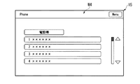
制御装置17は、例えば、第1表示部15のホーム画面W1において携帯電話機24に関する項目(Phone)が操作者によって選択されると、図7に示すように、第1表示部15のホーム画面を下位の階層の電話画面W4に切り替える。電話画面W4は、例えば、登録されている電話番号の項目と、電話帳などの各種設定を入力するためのメニュー項目となど、を備えている。
For example, when an item (Phone) related to the
制御装置17は、車載機器操作用の所定のキーボタンがインスツルメントパネル51に設けられている場合には、キーボタンが受け付ける操作者の入力操作に応じて、第1表示部15、第2表示部16、リヤカメラ21、ナビゲーション装置22、音響装置23、および携帯電話機24の各々の動作を制御する。
When a predetermined key button for operating the in-vehicle device is provided on the
制御装置17は、第1表示モードにおいて、常駐画面、ステアリングスイッチメニュー画面、および割り込み画面の何れか1つを第2表示部16に表示する。第1表示モードにおいて第2表示部16に表示される各画面は、1画面の範囲内に収まる表示内容を有しており、例えば複数画面による画面送りまたは1画面の範囲を超えてのスクロールなどには対応していない。
常駐画面は、初期状態において表示される。常駐画面は、例えば、時刻などの各種の情報と、第1表示部15の表示内容に関する情報となど、を備えている。制御装置17は、ステアリングスイッチ11の第3プッシュボタン(DISP)44が操作されると、複数の異なる常駐画面を順次に切り替えて第2表示部16に表示する。
In the first display mode, the
The resident screen is displayed in the initial state. The resident screen includes, for example, various types of information such as time and information related to the display contents of the
ステアリングスイッチメニュー画面は、ステアリングスイッチ11の第2プッシュボタン(MENU)43が操作された場合に表示される。ステアリングスイッチメニュー画面は、図8〜図12に示すように、階層構造を成すメインメニュー画面W5およびソースメニュー画面W6〜W8を備えている。メインメニュー画面W5は、図8および図10に示すように、最上位階層の画面である。ソースメニュー画面W6〜W8は、図9、図11、および図12に示すように、メインメニュー画面W5に対して下位の階層の画面である。
The steering switch menu screen is displayed when the second push button (MENU) 43 of the
メインメニュー画面W5およびソースメニュー画面W6〜W8は、ステアリングスイッチ11の各部位に対応付けられている操作内容の情報と、ステアリングスイッチ11の各部位の操作状態の情報と、ステアリングスイッチ11によって選択される項目と、を備えている。
操作内容の情報は、ステアリングスイッチ11の各部位に対応付けられている操作内容を記号または文字などによってガイドする情報である。操作内容の情報は、ステアリングスイッチ11を示す画像においてステアリングスイッチ11の各部位の中で操作可能な部位に対応付けられている記号または文字などを備えている。操作内容の情報は、例えば、複数の項目の中の何れか1つを選択する操作と、選択した項目を確定する操作と、第2表示部16に表示される画面を時系列上での1つ前の画面に戻す操作と、第2表示部16に表示されるステアリングスイッチメニュー画面を常駐画面に切り替える操作となど、をガイドする情報である。
The main menu screen W5 and the source menu screens W6 to W8 are selected by the operation switch information associated with each part of the
The operation content information is information that guides the operation content associated with each part of the
図8〜図12に示すステアリングスイッチメニュー画面において、ステアリングスイッチ11の各部位の中で操作可能な部位は、例えば、第1スイッチ(+)41a、第2スイッチ(−)41b、第3スイッチ(←)41c、第1プッシュボタン(SOURCE)42、および第2プッシュボタン(MENU)43である。
第1スイッチ(+)41aに対応付けられている操作内容は、上下方向に配列された複数の項目の中における選択を上方に移動させる操作である。第1スイッチ(+)41aの操作内容をガイドする記号61は、例えば、上方向を示す記号である。
第2スイッチ(−)41bに対応付けられている操作内容は、上下方向に配列された複数の項目の中における選択を下方に移動させる操作である。第2スイッチ(−)41bの操作内容をガイドする記号62は、例えば、下方向を示す記号である。
第3スイッチ(←)41cに対応付けられている操作内容は、第2表示部16に表示される画面を時系列上での1つ前の画面に戻す操作である。第3スイッチ(←)41cの操作内容をガイドする記号63は、例えば、湾曲した矢印の記号である。
第1プッシュボタン(SOURCE)42に対応付けられている操作内容は、第1スイッチ(+)41aまたは第2スイッチ(−)41bによって選択された項目を確定する操作である。第1プッシュボタン(SOURCE)42の操作内容をガイドする文字64は、例えば、「ENTER」の文字である。
第2プッシュボタン(MENU)43に対応付けられている操作内容は、第2表示部16に表示されるステアリングスイッチメニュー画面を常駐画面に切り替える操作である。第2プッシュボタン(MENU)43の操作内容をガイドする文字65は、例えば、「EXIT」の文字である。
In the steering switch menu screen shown in FIGS. 8 to 12, the operable parts among the parts of the
The operation content associated with the first switch (+) 41a is an operation for moving the selection among a plurality of items arranged in the vertical direction upward. The
The operation content associated with the second switch (−) 41b is an operation of moving the selection among the plurality of items arranged in the vertical direction downward. The
The operation content associated with the third switch (←) 41c is an operation for returning the screen displayed on the
The operation content associated with the first push button (SOURCE) 42 is an operation for confirming the item selected by the first switch (+) 41a or the second switch (−) 41b. The
The operation content associated with the second push button (MENU) 43 is an operation for switching the steering switch menu screen displayed on the
操作状態の情報は、ステアリングスイッチ11の各部位が実際に操作されているか否かを示す情報である。操作状態の情報は、例えば、ステアリングスイッチ11の各部位に対応付けられている操作内容の情報に対する強調表示の有無によって、各部位が実際に操作されているか否かを示す。
図8に示すメインメニュー画面W5、並びに図9および図12に示すソースメニュー画面W6、W8では、第1スイッチ(+)41aに対応付けられている操作内容の情報(例えば、上方向を示す記号61)が強調表示されることによって、実際に第1スイッチ(+)41aが操作されていることが示されている。
図10に示すメインメニュー画面W5および図11に示すソースメニュー画面W7では、第2スイッチ(−)41bに対応付けられている操作内容の情報(例えば、下方向を示す記号62)が強調表示されることによって、実際に第2スイッチ(−)41bが操作されていることが示されている。
The information on the operation state is information indicating whether each part of the
In the main menu screen W5 shown in FIG. 8 and the source menu screens W6 and W8 shown in FIGS. 9 and 12, information on the operation content associated with the first switch (+) 41a (for example, a symbol indicating the upward direction) 61) is highlighted, indicating that the first switch (+) 41a is actually operated.
In the main menu screen W5 shown in FIG. 10 and the source menu screen W7 shown in FIG. 11, information on the operation content associated with the second switch (−) 41b (for example, the
最上位階層のメインメニュー画面W5においてステアリングスイッチ11によって選択される項目は、図8および図10に示すように、第1表示部15、第2表示部16、ナビゲーション装置22、音響装置23、および携帯電話機24の各々を制御するための項目71〜74である。制御装置17は、ステアリングスイッチ11が受け付ける操作者の入力操作に応じて、第1表示部15、第2表示部16、ナビゲーション装置22、音響装置23、および携帯電話機24の各々の動作の少なくとも一部を制御する。
Items selected by the
制御装置17は、図8に示すように、ステアリングスイッチ11の第1スイッチ(+)41aの操作によって、メインメニュー画面W5において音響装置23に関する項目(Audio Menu)71が選択されると、記号61とともに、選択された項目71を強調表示する。制御装置17は、ステアリングスイッチ11の第1プッシュボタン(SOURCE)42の操作によって、項目71の選択が確定されると、図9に示すように、第2表示部16のメインメニュー画面W5を下位の階層のオーディオ用ソースメニュー画面W6に切り替える。
オーディオ用ソースメニュー画面W6においてステアリングスイッチ11によって選択される項目75〜78は、音声コンテンツを操作するための項目である。音声コンテンツを操作するための項目は、例えば、音声コンテンツのスキャンに関する項目75と、音声コンテンツの繰り返し出力に関する項目76と、音声コンテンツのランダム出力に関す項目77と、音声コンテンツの出力実行または出力停止に関する項目78となど、である。
制御装置17は、図9に示すように、ステアリングスイッチ11の第1スイッチ(+)41aの操作によって、オーディオ用ソースメニュー画面W6において音声コンテンツのスキャンに関する項目75が選択されると、記号61とともに、選択された項目75を強調表示する。
As shown in FIG. 8, when the item (Audio Menu) 71 related to the
As shown in FIG. 9, when the
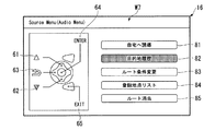
制御装置17は、図10に示すように、ステアリングスイッチ11の第2スイッチ(−)41bの操作によって、メインメニュー画面W5においてナビゲーション装置22に関する項目(Navigation Menu)72が選択されると、記号62とともに、選択された項目72を強調表示する。制御装置17は、ステアリングスイッチ11の第1プッシュボタン(SOURCE)42の操作によって、項目72の選択が確定されると、図11に示すように、第2表示部16のメインメニュー画面W5を下位の階層のナビゲーション用ソースメニュー画面W7に切り替える。
ナビゲーション用ソースメニュー画面W7においてステアリングスイッチ11によって選択される項目は、各種の設定を操作するための項目である。各種の設定を操作するための項目は、例えば、自宅への誘導に関する項目81と、目的地履歴に関する項目82と、経路案内のルート条件変更に関する項目83と、登録地点リストに関する項目84と、経路案内のルート消去に関する項目85となど、である。
As shown in FIG. 10, when the item (Navigation Menu) 72 related to the
Items selected by the
制御装置17は、図11に示すように、ステアリングスイッチ11の第2スイッチ(−)41bの操作によって、ナビゲーション用ソースメニュー画面W7において目的地履歴に関する項目(目的地履歴)82が選択されると、記号62とともに、選択された項目82を強調表示する。制御装置17は、ステアリングスイッチ11の第1プッシュボタン(SOURCE)42の操作によって、項目82の選択が確定されると、図12に示すように、第2表示部16のナビゲーション用ソースメニュー画面W7を下位の階層の目的地履歴用ソースメニュー画面W8に切り替える。
目的地履歴用ソースメニュー画面W8においてステアリングスイッチ11によって選択される項目は、目的地の履歴の項目86〜90である。目的地の履歴の項目86〜90は、例えば、直近の所定数の目的地または設定頻度が高い順の所定数の目的地の項目である。
制御装置17は、図12に示すように、第2表示部16に目的地履歴用ソースメニュー画面W8が表示されると、図13に示すように、第1表示部15に表示される画面をナビゲーション画面W2に切り替える。図13に示すナビゲーション画面W2は、例えば、車両1の現在位置P、目的地履歴用ソースメニュー画面W8に表示される5つの目的地Q1,…,Q5、および現在位置Pから第1目的地Q1までの経路Rなどを示す地図画像と、目的地などの各種設定を入力するためのメニュー項目となど、を備えている。
制御装置17は、図12に示すように、ステアリングスイッチ11の第1スイッチ(+)41aの操作によって、目的地履歴用ソースメニュー画面W8において第1目的地の項目(A)86が選択されると、記号61とともに、選択された項目86を強調表示する。制御装置17は、ステアリングスイッチ11の第1プッシュボタン(SOURCE)42の操作によって、項目86の選択が確定されると、図13に示すように、第1目的地Q1の周辺の地図画像と、現在位置Pから第1目的地Q1までの経路Rとを第1表示部15に表示する。
As shown in FIG. 11, when an item (destination history) 82 related to the destination history is selected on the navigation source menu screen W7 by the operation of the second switch (−) 41b of the
Items selected by the
When the destination history source menu screen W8 is displayed on the
As shown in FIG. 12, the
制御装置17は、ナビゲーション用ソースメニュー画面W7において、目的地履歴に関する項目82以外の他の項目が選択された場合には、各項目に対応付けられるソースメニュー画面を第2表示部16に表示する。
制御装置17は、第2表示部16にナビゲーション用ソースメニュー画面W7の各項目81〜85に対応付けられたソースメニュー画面が表示されると、第1表示部15にナビゲーション画面W2を表示する。ナビゲーション画面W2は、少なくとも第2表示部16に表示されているソースメニュー画面に対応する地図画像を備えている。
When an item other than the
When the source menu screen associated with each
制御装置17は、自宅への誘導に関する項目81に対応付けられたソースメニュー画面を第2表示部16に表示する場合には、複数の異なる経路探索条件の各々によって生成される車両1の現在位置から自宅への複数の経路を有する地図画像を第1表示部15に表示する。
制御装置17は、ルート条件変更に関する項目83に対応付けられたソースメニュー画面を第2表示部16に表示する場合には、複数の異なる経路探索条件の各々によって生成される車両1の現在位置から目的地への複数の経路を有する地図画像を第1表示部15に表示する。
制御装置17は、登録地点リストに関する項目84に対応付けられたソースメニュー画面を第2表示部16に表示する場合には、複数の登録地点を有する地図画像を第1表示部15に表示する。
制御装置17は、ルート消去に関する項目85に対応付けられたソースメニュー画面を第2表示部16に表示する場合には、現時点で選択されている経路を有する地図画像を第1表示部15に表示する。
When the
When displaying the source menu screen associated with the
The
When the
割り込み画面は、所定条件において常駐画面から切り替えられる画面である。割り込み画面は、例えば、リヤカメラ21によって撮像される車両1の後方の撮像画像を表示するリヤカメラ画像画面W10、または携帯電話機24の着信を報知する着信画面W11などである。
制御装置17は、シフトポジションセンサ13によってシフトポジションがリバースであることが検出されると、図14に示すように、リヤカメラ画像画面W10を第2表示部16に表示する。リヤカメラ画像画面W10は、車両1の後方の撮像画像に加えて、セレクトレバー50によってシフトポジションのリバースが選択されていることを示す情報を備えていてもよい。制御装置17は、シフトポジションセンサ13によってシフトポジションがリバースからリバース以外に切り替えられたことが検出されると、第2表示部16のリヤカメラ画像画面W10をリヤカメラ画像画面W10が表示される直前の画面に切り替える。
The interrupt screen is a screen that can be switched from the resident screen under a predetermined condition. The interrupt screen is, for example, a rear camera image screen W10 that displays a captured image behind the
When the
制御装置17は、携帯電話機24に着信が生じると、図15に示すように、着信画面W11を第2表示部16に表示する。着信画面W11は、例えば、発信元の電話番号などの情報と、着信操作をガイドする情報(操作ガイド)となど、を備えている。着信操作をガイドする情報は、例えば、ステアリングスイッチ11を示す画像においてステアリングスイッチ11の各部位の中で操作可能な部位に対応付けられている着信操作を記号または文字などによってガイドする情報である。図15に示す着信画面では、ステアリングスイッチ11の各部位の中で着信操作可能な部位は、第1プッシュボタン(SOURCE)42および第2プッシュボタン(MENU)43である。第1プッシュボタン(SOURCE)42および第2プッシュボタン(MENU)43には、着信に対する通話開始または通話終了の操作をガイドする文字が対応付けられている。第1プッシュボタン(SOURCE)42および第2プッシュボタン(MENU)43の操作内容をガイドする文字91は、例えば、「通話/終了」の文字である。
制御装置17は、携帯電話機24の着信に対する通話が終了された場合には、第2表示部16の着信画面W11を着信画面W11が表示される直前の画面に切り替える。
When an incoming call occurs in the
When the call for the incoming call of the
制御装置17は、第2表示モードにおいて、例えば、第1表示部15の表示内容の少なくとも一部と、第2表示部16の表示内容の少なくとも一部とを交換する。制御装置17は、第2表示モードにおいて、例えば、常駐画面、ステアリングスイッチメニュー画面、および割り込み画面の何れか1つを第1表示部15に表示する。制御装置17は、第2表示モードにおいて、例えば、第1表示部15の表示内容に対応して地図画像を備えるナビゲーション画面などを第2表示部16に表示する。
In the second display mode, the
本実施形態による車両用表示装置10は上記構成を備えており、次に、車両用表示装置10の動作について、図16を参照して説明する。
The
制御装置17は、以下に示すステップS01からステップS09の処理を、例えば所定周期などで繰り返し実行する。
制御装置17は、車速が閾値よりも大きいか否かを判定する(ステップS01)。
この判定結果が「NO」の場合には、制御装置17は、処理をステップS02に進める(ステップS01のNO側)。
一方、この判定結果が「YES」の場合には、制御装置17は、処理をステップS03に進める(ステップS01のYES側)。
制御装置17は、第2表示モードを実行し、処理をエンドに進める(ステップS02)。
制御装置17は、第1表示モードを実行する(ステップS03)。
The
The
If this determination is “NO”, the
On the other hand, if this determination is “YES”, the
The
The
制御装置17は、ステアリングスイッチ11の第2プッシュボタン(MENU)43が操作されたか否かを判定する(ステップS04)。
この判定結果が「NO」の場合には、制御装置17は、処理をステップS06に進める(ステップS04のNO側)。
一方、この判定結果が「YES」の場合には、制御装置17は、処理をステップS05に進める(ステップS04のYES側)。
制御装置17は、ステアリングスイッチメニュー(STRGMenu)画面を第2表示部16に表示する(ステップS05)。
The
When the determination result is “NO”, the
On the other hand, if the determination result is “YES”, the
The
制御装置17は、携帯電話機24に着信が生じたか否かを判定する(ステップS06)。
この判定結果が「NO」の場合には、制御装置17は、処理をステップS08に進める(ステップS06のNO側)。
一方、この判定結果が「YES」の場合には、制御装置17は、処理をステップS07に進める(ステップS06のYES側)。
制御装置17は、着信画面を第2表示部16に表示する(ステップS07)。
The
When the determination result is “NO”, the
On the other hand, if the determination result is “YES”, the
The
制御装置17は、シフトポジションがリバースであるか否かを判定する(ステップS08)。
この判定結果が「NO」の場合には、制御装置17は、処理をエンドに進める(ステップS08のNO側)。
一方、この判定結果が「YES」の場合には、制御装置17は、処理をステップS09に進める(ステップS08のYES側)。
制御装置17は、リヤカメラ画像画面を第2表示部16に表示する(ステップS09)。そして、制御装置17は、処理をエンドに進める。
The
If this determination is “NO”, the
On the other hand, if the determination result is “YES”, the
The
上述したように、本実施の形態による車両用表示装置10によれば、車両1の走行時にステアリングスイッチ11の操作状態を第2表示部16に表示する制御装置17を備えるので、第1表示部15の地図などの表示内容に対する視認性を確保しながら、ステアリングスイッチ11の操作状態を運転者に容易に確認させることができる。
さらに、車両1を運転中の運転者がステアリングスイッチ11の操作状態を直接に視認することが難しい場合であっても、第2表示部16によってステアリングスイッチ11の操作状態を運転者に容易に確認させることができる。
さらに、制御装置17はステアリングスイッチ11の実際の操作状態を強調して表示するので、車両1の運転中であってもステアリングスイッチ11の操作状態を運転者に容易に確認させることができる。
さらに、第2表示部16は第1表示部15よりも運転者が視認し易い位置に配置されているので、車両1の運転中であってもステアリングスイッチ11の操作状態を運転者に容易に確認させることができる。
As described above, the
Furthermore, even if it is difficult for the driver who is driving the
Furthermore, since the
Furthermore, since the
さらに、制御装置17は第2表示部16の表示内容を1画面の範囲内に収まる表示内容とするので、例えば画面送りまたはスクロールなどが必要になる場合に比べて、運転者の注意が散漫になることを防ぎ、視線移動が増大することを防ぐことができる。これにより目的地履歴の一覧または登録地点の一覧が一画面の範囲内に収まるように表示されるので、目的地を設定する際などに運転者の注意が散漫になることを防ぐことができる。
さらに、第2表示部16に表示される目的地または登録地点などの位置の周辺の地図が第1表示部15に表示されるので、地図に対する視認性を容易に確保して、運転者に位置を把握させ易くすることができる。
さらに、制御装置17は携帯電話機24の着信時に通話のための操作ガイドを第2表示部16に表示するので、車両1の運転中であっても運転者を慌てさせることなく、ステアリングスイッチ11によって携帯電話機24を容易に操作させることができる。
さらに、車両1の停止時などのように運転者がステアリングスイッチ11の操作状態を直接に視認する余裕がある場合には、第1表示部15の表示内容と第2表示部16の表示内容とを交換することによって、ステアリングスイッチ11の操作状態以外の情報を第2表示部16に表示させることができる。
Furthermore, since the
Further, since a map around the location such as the destination or registration point displayed on the
Further, since the
Further, when there is a margin for the driver to visually recognize the operation state of the
以下、上述した実施形態の変形例について説明する。
上述した実施形態において、車両用表示装置10は、インスツルメントパネル51に配置された第1表示部15および第2表示部16を備えるとしたが、これに限定されない。
車両用表示装置10は、第1表示部15および第2表示部16の組み合わせの代わりに、図17に示す複数の表示部の中の何れか2つの組み合わせを備えてもよい。複数の表示部は、第1表示部15および第2表示部16の何れかに加えて、例えば、HUD(ヘッドアップディスプレイ)装置92、MID(マルチインフォメーションディスプレイ)装置93、およびインホイールエリアディスプレイ94などを備えている。
Hereinafter, modifications of the above-described embodiment will be described.
In the above-described embodiment, the
The
HUD装置92は、例えば、運転席前方のフロントガラス52の一部に画像を投影表示、または運転席前方のインスツルメントパネル51の上方に画像を虚像表示する。
MID装置93は、例えば、運転席前方のインスツルメントパネル51に設けられた車速計等の計器類を備えるメータパネル部に配置されている。
インホイールエリアディスプレイ94は、例えば、ステアリングホイール30の上部に配置されている。
HUD装置92またはMID装置93は、第2表示部16よりも車両1の運転者が視認し易い位置に配置されている。第2表示部16は、第1表示部15よりも車両1の運転者が視認し易い位置に配置されている。上述した実施形態の第1表示部15と第2表示部16との組み合わせの代わりに、例えば、HUD装置92またはMID装置93と第2表示部16とを組み合わせてもよいし、あるいは、HUD装置92またはMID装置93と第1表示部15とを組み合わせてもよい。
For example, the
The
The in-wheel area display 94 is disposed on the
The
上述した実施形態において、車両用表示装置10は、ステアリングスイッチ11が操作されたことを示すLEDランプなどの灯体を備えてもよい。灯体は、例えばインスツルメントパネル51またはステアリングホイール30などに配置される。灯体は、ステアリングスイッチ11の各部位が操作された場合に点灯することによって、ステアリングスイッチ11が操作されたことを報知する。例えば図17に示す車両1において、灯体95はステアリングホイール30に配置されている。
In the above-described embodiment, the
上述した実施形態において、制御装置17は、車両1の走行時に車速センサ12によって検出される車速が所定の閾値よりも大きい場合に第1表示モードを実行するとしたが、これに限定されない。制御装置17は、車両1の車速にかかわらずに常に第1表示モードを実行し、第2表示モードを実行しなくてもよい。この場合の第2表示部16は、タッチパネルでなくともよく、操作者の手指による入力操作を受け付けなくてもよい。
In the above-described embodiment, the
上述した実施形態では、ステアリングスイッチメニュー画面において、ステアリングスイッチ11の実際に操作されている部位に対応付けられている操作内容の情報と、ステアリングスイッチ11の操作によって選択される項目とが強調表示されるとしたが、これに限定されない。
制御装置17は、ステアリングスイッチメニュー画面において、ステアリングスイッチ11の操作可能な部位に対応付けられている操作内容の情報を強調表示してもよい。
制御装置17は、ステアリングスイッチメニュー画面において、ステアリングスイッチ11の操作によって選択される複数の項目の中における操作可能な方向の情報を表示してもよい。例えば上述した実施形態の図8に示すメインメニュー画面W5において、制御装置17は、複数の項目71〜74の中における操作可能な方向として、音響装置23に関する項目(Audio Menu)71からナビゲーション装置22に関する項目(Navigation Menu)72に向かう下向きの方向の情報を表示してもよい。
In the embodiment described above, on the steering switch menu screen, information on the operation content associated with the part where the
The
The
上述した実施形態において、制御装置17の一部、または全部は、CPU(Central Processing Unit)がプログラムを実行することにより機能する機能部であってもよい。また、これら構成を、LSI(Large Scale Integration)等の集積回路として実現してもよく、これら構成の各機能ブロックは個別にプロセッサ化してもよいし、一部、または全部を集積してプロセッサ化してもよい。また、集積回路化の手法はLSIに限らず専用回路、または汎用プロセッサで実現してもよい。また、半導体技術の進歩によりLSIに代替する集積回路化の技術が出現した場合、当該技術による集積回路を用いてもよい。
In the embodiment described above, a part or all of the
本発明の実施形態は、例として提示したものであり、発明の範囲を限定することは意図していない。これら実施形態は、その他の様々な形態で実施されることが可能であり、発明の要旨を逸脱しない範囲で、種々の省略、置き換え、変更を行うことができる。これら実施形態やその変形は、発明の範囲や要旨に含まれると同様に、特許請求の範囲に記載された発明とその均等の範囲に含まれるものである。 The embodiments of the present invention are presented as examples and are not intended to limit the scope of the invention. These embodiments can be implemented in various other forms, and various omissions, replacements, and changes can be made without departing from the spirit of the invention. These embodiments and their modifications are included in the scope and gist of the invention, and are also included in the invention described in the claims and the equivalents thereof.
1…車両、10…車両用表示装置、11…ステアリングスイッチ(操作部、スイッチ)、12…車速センサ(車速検出部)、13…シフトポジションセンサ、15…第1表示部、16…第2表示部、17…制御装置(制御部)、21…リヤカメラ、22…ナビゲーション装置、23…音響装置、24…携帯電話機(電話機)、50…セレクトレバー(操作部)
DESCRIPTION OF
Claims (11)
前記第1表示部の表示内容を操作するための情報を表示する第2表示部と、
車両の運転者の操作入力を受け付ける第1表示部近傍以外および第2表示部近傍以外に配置された操作部と、
前記車両の速度を検出する車速検出部と、
前記車速検出部により検出される前記車両の速度が閾値よりも大きい場合に、前記操作部の操作状態の情報を前記第2表示部に表示する制御部と、
を備える、
ことを特徴とする車両用表示装置。 A first display for displaying at least a map;
A second display for displaying information for operating the display content of the first display;
An operation unit disposed outside the vicinity of the first display unit and the vicinity of the second display unit for receiving an operation input of the driver of the vehicle;
A vehicle speed detector for detecting the speed of the vehicle;
A control unit that displays information on an operation state of the operation unit on the second display unit when the vehicle speed detected by the vehicle speed detection unit is greater than a threshold;
Comprising
A display device for a vehicle.
ことを特徴とする請求項1に記載の車両用表示装置。 The operation unit is a switch disposed on a steering wheel of the vehicle.
The vehicular display device according to claim 1.
ことを特徴とする請求項2に記載の車両用表示装置。 The control unit highlights and displays an actual operation state among a plurality of operation states of the switch.
The vehicle display device according to claim 2.
ことを特徴とする請求項1から請求項3の何れか1項に記載の車両用表示装置。 The second display unit is disposed at a position that is easier for the driver of the vehicle to visually recognize than the first display unit.
The vehicle display device according to any one of claims 1 to 3, wherein the display device for a vehicle is used.
ことを特徴とする請求項1から請求項4の何れか1項に記載の車両用表示装置。 The control unit sets the display content of the second display unit to display content that falls within a range of one screen.
The vehicular display device according to any one of claims 1 to 4, wherein the vehicular display device is provided.
ことを特徴とする請求項5に記載の車両用表示装置。 The control unit displays a list of destination histories on the second display unit.
The vehicular display device according to claim 5.
ことを特徴とする請求項5または請求項6に記載の車両用表示装置。 The control unit displays a list of registration points on the second display unit;
The vehicular display device according to claim 5, wherein the vehicular display device is provided.
ことを特徴とする請求項5から請求項7の何れか1項に記載の車両用表示装置。 The control unit causes the first display unit to display a map around the position displayed on the second display unit.
The vehicle display device according to any one of claims 5 to 7, wherein
ことを特徴とする請求項1から請求項8の何れか1項に記載の車両用表示装置。 The control unit causes an operation guide for a call to be displayed on the second display unit when an incoming call of a telephone that can be operated by the operation unit is received.
The vehicular display device according to any one of claims 1 to 8, wherein
ことを特徴とする請求項1から請求項9の何れか1項に記載の車両用表示装置。 The control unit exchanges and displays the display content of the first display unit and the display content of the second display unit when the vehicle speed detected by the vehicle speed detection unit is equal to or less than the threshold value.
The vehicular display device according to any one of claims 1 to 9, wherein
前記第1表示部の表示内容を操作するための情報を表示する第2表示部と、
車両の運転者の操作入力を受け付けるステアリングホイールに配置されるスイッチ形状の操作部と、
前記操作部の操作状態の情報を略スイッチ形状で前記第2表示部に表示する制御部と、
を備える、
ことを特徴とする車両用表示装置。 A first display for displaying at least a map;
A second display for displaying information for operating the display content of the first display;
A switch-shaped operation unit disposed on a steering wheel that receives an operation input of a vehicle driver;
A control unit for displaying information on an operation state of the operation unit on the second display unit in a substantially switch shape;
Comprising
A display device for a vehicle.
Priority Applications (2)
| Application Number | Priority Date | Filing Date | Title |
|---|---|---|---|
| JP2016051333A JP2017165215A (en) | 2016-03-15 | 2016-03-15 | Vehicle display device |
| US15/459,320 US20170269704A1 (en) | 2016-03-15 | 2017-03-15 | Display device for vehicle |
Applications Claiming Priority (1)
| Application Number | Priority Date | Filing Date | Title |
|---|---|---|---|
| JP2016051333A JP2017165215A (en) | 2016-03-15 | 2016-03-15 | Vehicle display device |
Publications (1)
| Publication Number | Publication Date |
|---|---|
| JP2017165215A true JP2017165215A (en) | 2017-09-21 |
Family
ID=59855552
Family Applications (1)
| Application Number | Title | Priority Date | Filing Date |
|---|---|---|---|
| JP2016051333A Pending JP2017165215A (en) | 2016-03-15 | 2016-03-15 | Vehicle display device |
Country Status (2)
| Country | Link |
|---|---|
| US (1) | US20170269704A1 (en) |
| JP (1) | JP2017165215A (en) |
Cited By (5)
| Publication number | Priority date | Publication date | Assignee | Title |
|---|---|---|---|---|
| JP2019131135A (en) * | 2018-02-02 | 2019-08-08 | 株式会社デンソー | Display system |
| CN110103857A (en) * | 2019-05-09 | 2019-08-09 | 北京伏羲车联信息科技有限公司 | Control method for vehicle, device and electronic equipment |
| WO2019225305A1 (en) * | 2018-05-25 | 2019-11-28 | 株式会社デンソー | Display control system for vehicle, display control program for vehicle,, and recording medium |
| WO2019244347A1 (en) * | 2018-06-22 | 2019-12-26 | 三菱電機株式会社 | Vehicle-mounted operation device |
| WO2020066935A1 (en) * | 2018-09-28 | 2020-04-02 | パナソニックIpマネジメント株式会社 | Apparatus control system, mobile body, apparatus control method, and program |
Families Citing this family (8)
| Publication number | Priority date | Publication date | Assignee | Title |
|---|---|---|---|---|
| US10459616B2 (en) * | 2016-04-15 | 2019-10-29 | Toyota Motor Engineering & Manufacturing North America, Inc. | Automatic full screen display |
| WO2019180875A1 (en) * | 2018-03-22 | 2019-09-26 | 本田技研工業株式会社 | Saddle riding-type vehicle |
| US10780909B2 (en) * | 2018-08-03 | 2020-09-22 | Tesla, Inc. | User interface for steering wheel |
| JP6778735B2 (en) * | 2018-12-26 | 2020-11-04 | 本田技研工業株式会社 | Display device, display method, and program |
| JP7415855B2 (en) * | 2020-08-31 | 2024-01-17 | トヨタ自動車株式会社 | Vehicle information display system |
| DE102021208436A1 (en) * | 2021-08-04 | 2023-02-09 | Volkswagen Aktiengesellschaft | Display system for a vehicle and method for optically highlighting different operating states in the vehicle |
| JP2023044096A (en) | 2021-09-17 | 2023-03-30 | トヨタ自動車株式会社 | In-vehicle display control device, in-vehicle display system, vehicle, display method, and program |
| JP2023166820A (en) * | 2022-05-10 | 2023-11-22 | トヨタ自動車株式会社 | Display control device for vehicle, display control system for vehicle, vehicle, and display control method and program for vehicle |
Citations (7)
| Publication number | Priority date | Publication date | Assignee | Title |
|---|---|---|---|---|
| JP2004144712A (en) * | 2002-10-28 | 2004-05-20 | Denso Corp | Car navigation system |
| JP2006096245A (en) * | 2004-09-30 | 2006-04-13 | Mazda Motor Corp | Information display device for vehicle |
| JP2007076384A (en) * | 2005-09-09 | 2007-03-29 | Mazda Motor Corp | Information display unit for vehicle |
| JP2008002958A (en) * | 2006-06-22 | 2008-01-10 | Sharp Corp | Car navigation system |
| JP2010105417A (en) * | 2008-10-28 | 2010-05-13 | Mitsubishi Motors Corp | On-vehicle electronic equipment |
| JP2014203318A (en) * | 2013-04-08 | 2014-10-27 | 三菱電機株式会社 | Display information generation device and display information generation method |
| JP2015151059A (en) * | 2014-02-18 | 2015-08-24 | 本田技研工業株式会社 | On-vehicle apparatus operation device |
Family Cites Families (3)
| Publication number | Priority date | Publication date | Assignee | Title |
|---|---|---|---|---|
| US8775964B2 (en) * | 2005-03-23 | 2014-07-08 | Core Wireless Licensing, S.a.r.l. | Method and mobile terminal device for mapping a virtual user input interface to a physical user input interface |
| JP2009154647A (en) * | 2007-12-26 | 2009-07-16 | Aisin Aw Co Ltd | Multi-screen display and program of the same |
| JP5876363B2 (en) * | 2012-04-12 | 2016-03-02 | 株式会社デンソー | Control device and program |
-
2016
- 2016-03-15 JP JP2016051333A patent/JP2017165215A/en active Pending
-
2017
- 2017-03-15 US US15/459,320 patent/US20170269704A1/en not_active Abandoned
Patent Citations (7)
| Publication number | Priority date | Publication date | Assignee | Title |
|---|---|---|---|---|
| JP2004144712A (en) * | 2002-10-28 | 2004-05-20 | Denso Corp | Car navigation system |
| JP2006096245A (en) * | 2004-09-30 | 2006-04-13 | Mazda Motor Corp | Information display device for vehicle |
| JP2007076384A (en) * | 2005-09-09 | 2007-03-29 | Mazda Motor Corp | Information display unit for vehicle |
| JP2008002958A (en) * | 2006-06-22 | 2008-01-10 | Sharp Corp | Car navigation system |
| JP2010105417A (en) * | 2008-10-28 | 2010-05-13 | Mitsubishi Motors Corp | On-vehicle electronic equipment |
| JP2014203318A (en) * | 2013-04-08 | 2014-10-27 | 三菱電機株式会社 | Display information generation device and display information generation method |
| JP2015151059A (en) * | 2014-02-18 | 2015-08-24 | 本田技研工業株式会社 | On-vehicle apparatus operation device |
Cited By (11)
| Publication number | Priority date | Publication date | Assignee | Title |
|---|---|---|---|---|
| JP2019131135A (en) * | 2018-02-02 | 2019-08-08 | 株式会社デンソー | Display system |
| WO2019225305A1 (en) * | 2018-05-25 | 2019-11-28 | 株式会社デンソー | Display control system for vehicle, display control program for vehicle,, and recording medium |
| JP2019202723A (en) * | 2018-05-25 | 2019-11-28 | 株式会社デンソー | Display control system for vehicle, display control program for vehicle, and recording medium |
| JP7144721B2 (en) | 2018-05-25 | 2022-09-30 | 株式会社デンソー | VEHICLE DISPLAY CONTROL SYSTEM, VEHICLE DISPLAY CONTROL PROGRAM AND STORAGE MEDIUM |
| WO2019244347A1 (en) * | 2018-06-22 | 2019-12-26 | 三菱電機株式会社 | Vehicle-mounted operation device |
| JPWO2019244347A1 (en) * | 2018-06-22 | 2020-12-17 | 三菱電機株式会社 | In-vehicle operation device |
| WO2020066935A1 (en) * | 2018-09-28 | 2020-04-02 | パナソニックIpマネジメント株式会社 | Apparatus control system, mobile body, apparatus control method, and program |
| JP2020055383A (en) * | 2018-09-28 | 2020-04-09 | パナソニックIpマネジメント株式会社 | Device control system, mobile body, device control method and program |
| JP7165864B2 (en) | 2018-09-28 | 2022-11-07 | パナソニックIpマネジメント株式会社 | Device control system, moving body, device control method and program |
| US11679677B2 (en) | 2018-09-28 | 2023-06-20 | Panasonic Intellectual Property Management Co., Ltd. | Device control system, moving vehicle, device control method, and non-transitory storage medium |
| CN110103857A (en) * | 2019-05-09 | 2019-08-09 | 北京伏羲车联信息科技有限公司 | Control method for vehicle, device and electronic equipment |
Also Published As
| Publication number | Publication date |
|---|---|
| US20170269704A1 (en) | 2017-09-21 |
Similar Documents
| Publication | Publication Date | Title |
|---|---|---|
| JP2017165215A (en) | Vehicle display device | |
| KR102176305B1 (en) | Method and device for representing recommended operating actions of a proposal system and interaction with the proposal system | |
| US9361000B2 (en) | Information display device for vehicle | |
| EP3165994B1 (en) | Information processing device | |
| WO2016132876A1 (en) | Information processing device | |
| JP6900133B2 (en) | Gesture operation device and gesture operation method | |
| CN107918504B (en) | Vehicle-mounted operating device | |
| JP2014113873A (en) | Vehicular cooperation system | |
| JP2011203982A (en) | Operation system, operation device, and command execution method | |
| JP2011116304A (en) | User interface device | |
| JP2013222214A (en) | Display operation device and display system | |
| US20130335401A1 (en) | Multifunctional Operating Device | |
| KR101558354B1 (en) | Blind control system for vehicle | |
| JP2006264615A (en) | Display device for vehicle | |
| JP2016097928A (en) | Vehicular display control unit | |
| JP6135400B2 (en) | Display device | |
| JP2004251738A (en) | Vehicle-mounted information display | |
| JP2018195134A (en) | On-vehicle information processing system | |
| JP2013006472A (en) | Display apparatus | |
| CN109656434B (en) | Display control device | |
| WO2016031152A1 (en) | Input interface for vehicle | |
| JP2016215879A (en) | Vehicle information providing device | |
| JP6372246B2 (en) | Vehicle information providing device | |
| JP5728957B2 (en) | Vehicle control device | |
| JP6384869B2 (en) | Information processing system and computer program |
Legal Events
| Date | Code | Title | Description |
|---|---|---|---|
| A131 | Notification of reasons for refusal |
Free format text: JAPANESE INTERMEDIATE CODE: A131 Effective date: 20171219 |
|
| A977 | Report on retrieval |
Free format text: JAPANESE INTERMEDIATE CODE: A971007 Effective date: 20171221 |
|
| A521 | Request for written amendment filed |
Free format text: JAPANESE INTERMEDIATE CODE: A523 Effective date: 20180214 |
|
| A02 | Decision of refusal |
Free format text: JAPANESE INTERMEDIATE CODE: A02 Effective date: 20180619 |