JP2017147848A - Non-contact power supply device - Google Patents
Non-contact power supply device Download PDFInfo
- Publication number
- JP2017147848A JP2017147848A JP2016027934A JP2016027934A JP2017147848A JP 2017147848 A JP2017147848 A JP 2017147848A JP 2016027934 A JP2016027934 A JP 2016027934A JP 2016027934 A JP2016027934 A JP 2016027934A JP 2017147848 A JP2017147848 A JP 2017147848A
- Authority
- JP
- Japan
- Prior art keywords
- power
- power supply
- voltage
- power feeding
- circuit
- Prior art date
- Legal status (The legal status is an assumption and is not a legal conclusion. Google has not performed a legal analysis and makes no representation as to the accuracy of the status listed.)
- Granted
Links
- 238000004519 manufacturing process Methods 0.000 claims abstract description 56
- 239000000758 substrate Substances 0.000 claims abstract description 27
- 238000001514 detection method Methods 0.000 claims abstract description 22
- 238000006243 chemical reaction Methods 0.000 claims abstract description 5
- 238000012544 monitoring process Methods 0.000 claims description 6
- 239000003990 capacitor Substances 0.000 description 16
- 238000010586 diagram Methods 0.000 description 5
- 238000010168 coupling process Methods 0.000 description 4
- 238000013459 approach Methods 0.000 description 3
- 230000008859 change Effects 0.000 description 3
- 238000000034 method Methods 0.000 description 3
- 238000000926 separation method Methods 0.000 description 3
- 230000004048 modification Effects 0.000 description 2
- 238000012986 modification Methods 0.000 description 2
- 238000012545 processing Methods 0.000 description 2
- 230000009467 reduction Effects 0.000 description 2
- 230000000087 stabilizing effect Effects 0.000 description 2
- HEZMWWAKWCSUCB-PHDIDXHHSA-N (3R,4R)-3,4-dihydroxycyclohexa-1,5-diene-1-carboxylic acid Chemical compound O[C@@H]1C=CC(C(O)=O)=C[C@H]1O HEZMWWAKWCSUCB-PHDIDXHHSA-N 0.000 description 1
- 230000005856 abnormality Effects 0.000 description 1
- 238000004891 communication Methods 0.000 description 1
- 230000006866 deterioration Effects 0.000 description 1
- 230000000694 effects Effects 0.000 description 1
- 238000009499 grossing Methods 0.000 description 1
- 238000007689 inspection Methods 0.000 description 1
- 230000007246 mechanism Effects 0.000 description 1
- 230000008569 process Effects 0.000 description 1
- 229910000679 solder Inorganic materials 0.000 description 1
- 230000001629 suppression Effects 0.000 description 1
Images


Landscapes
- Charge And Discharge Circuits For Batteries Or The Like (AREA)
- Current-Collector Devices For Electrically Propelled Vehicles (AREA)
Abstract
Description
本発明は、固定部から移動体に非接触で給電する非接触給電装置に関する。 The present invention relates to a non-contact power feeding device that feeds power from a fixed part to a moving body in a non-contact manner.
多数の部品が装着された基板を生産する基板生産機として、はんだ印刷機、電子部品装着機、リフロー機、基板検査機などがある。これらの設備を連結して基板生産ラインを構成することが一般的になっている。さらに、モジュール化された同じ大きさの基板生産機を列設して基板生産ラインを構成する場合も多い。モジュール化された基板生産機を用いることにより、ラインの組み替え時やラインを長大化する増設時の段取り替え作業が容易になり、フレキシブルな基板生産ラインが実現される。 As a board production machine for producing a board on which a large number of parts are mounted, there are a solder printer, an electronic parts mounting machine, a reflow machine, a board inspection machine, and the like. It has become common to configure a substrate production line by connecting these facilities. Furthermore, there are many cases where a substrate production line is configured by arranging modular board production machines of the same size. By using a modularized board production machine, it is easy to change the setup when changing the line or adding a longer line, and a flexible board production line is realized.
近年、基板生産ラインの各基板生産機で使用する機材や部材を、基板生産ラインに沿って移動する移動体に搬送させ、省力化および自動化を推進することが検討されている。さらに、移動体への給電手段として、非接触給電装置が考えられている。なお、非接触給電装置の用途は、基板生産ラインに限定されず、他の製品を生産する組立ラインや加工ライン、電動車両の走行中給電など幅広い分野にわたっている。この種の非接触給電装置に関する技術例が特許文献1、2に開示されている。
In recent years, it has been studied to promote labor saving and automation by transporting equipment and members used in each board production machine of a board production line to a moving body that moves along the board production line. Furthermore, a non-contact power feeding device is considered as a power feeding means to the moving body. The application of the non-contact power feeding device is not limited to the board production line, but covers a wide range of fields such as an assembly line and a processing line for producing other products, and power feeding during running of an electric vehicle.
特許文献1のワイヤレス受電装置は、受電コイルと、受電コイルが受電した交流電力を直流電力に整流する整流部と、直流電力を蓄電器に充電する充電部と、整流部の出力電圧値を検出する電圧検出部と、充電部に並列に接続されるスイッチング素子を含む電力抑制部と、スイッチング素子の動作を制御する制御部と、を備えている。そして、制御部は、出力電圧値が第1の基準電圧値を上回ったときにスイッチング素子をオンに制御する。これによれば、受電装置に過電圧などの異常が生じた場合、過電圧による大電流が充電部とスイッチング素子に分散されて流れることから劣化や破損を防止できる、とされている。 The wireless power receiving apparatus disclosed in Patent Document 1 detects a power receiving coil, a rectifying unit that rectifies AC power received by the power receiving coil into DC power, a charging unit that charges the battery with DC power, and an output voltage value of the rectifying unit. A voltage detection unit; a power suppression unit including a switching element connected in parallel to the charging unit; and a control unit that controls the operation of the switching element. Then, the control unit controls the switching element to turn on when the output voltage value exceeds the first reference voltage value. According to this, when an abnormality such as an overvoltage occurs in the power receiving device, a large current due to the overvoltage is distributed and flows between the charging unit and the switching element, so that deterioration and breakage can be prevented.
特許文献2の直動機構用無接触給電装置は、1次側トランスユニット(給電素子)を移動体の全移動範囲にわたり複数個間欠的に配置し、これらの1次側トランスユニットを高周波インバータにそれぞれスイッチを介して並列接続し、2次側トランスユニット(受電素子)を移動体に取り付けている。実施形態には、連結部品を用いて移動体に2個の2次側トランスユニットを搭載する構成例が開示されている。これによれば、移動体がどの位置にあっても、2個の2次側トランスユニットのうち1個は常に電力供給を受けられることになる、とされている。
In the non-contact power feeding device for a linear motion mechanism disclosed in
ところで、特許文献1の技術例では、蓄電器の充電状態が高められて充電電流値が小さくなると入力インピーダンスが上昇し、受電コイルの両端にかかる電圧が上昇してしまうおそれがある。このような負荷変動による過電圧のおそれを解消するため、特許文献2に例示されるように複数の受電コイル(2次側トランスユニット)を備えて、非接触給電を安定化する方策が考えられる。これによれば、充電部(充電回路)および蓄電器(バッテリ)を省略して、直接的に電気負荷を駆動することができる。充電部および蓄電器の省略は、受電装置を搭載した移動体の小形軽量化に貢献できて好ましい。
By the way, in the technical example of patent document 1, when the charge condition of a capacitor | condenser is raised and charging current value becomes small, input impedance will rise and there exists a possibility that the voltage concerning the both ends of a receiving coil may rise. In order to eliminate the fear of overvoltage due to such load fluctuations, there can be considered a method of stabilizing the non-contact power feeding by providing a plurality of power receiving coils (secondary transformer units) as exemplified in
しかしながら、この方策を採用しても過電圧のおそれは完全には解消されず、複数組の受電コイルおよび整流部に対してそれぞれ電圧検出部を設けることになる。このため、受電装置を搭載した移動体は、大形化しかつ重量が増加して、移動に必要な駆動力が増加する。特に、駆動力を発生する電動式の駆動源を移動体に搭載している構成では、給電電力を増加させるために受電コイルの大形化が必要となり、移動体のさらなる重厚長大化を招いてしまう。 However, even if this measure is adopted, the risk of overvoltage is not completely eliminated, and a voltage detection unit is provided for each of a plurality of sets of power reception coils and rectification units. For this reason, the moving body on which the power receiving device is mounted is increased in size and weight, and the driving force necessary for movement increases. In particular, in a configuration in which an electric drive source that generates a driving force is mounted on a moving body, it is necessary to increase the size of the receiving coil in order to increase the feed power, which leads to further increase in the weight and length of the moving body. End up.
本発明は、上記背景技術の問題点に鑑みてなされたものであり、給電対象となる移動体に簡易な構成の電圧検出回路を備えて保護機能を高めつつ、移動体の小形軽量化を実現した非接触給電装置を提供することを解決すべき課題とする。 The present invention has been made in view of the above-described problems of the background art, and a moving body that is a power supply target includes a voltage detection circuit with a simple configuration to enhance a protection function and achieve a reduction in size and weight of the moving body. An object to be solved is to provide a contactless power feeding device.
上記課題を解決する本発明の非接触給電装置は、固定部に設定された移動方向に沿って配置される複数の給電素子と、前記複数の給電素子に交流電力を供給する交流電源と、前記移動方向に沿って移動する移動体上に前記移動方向に沿って配置され、前記複数の給電素子のうち対向するいずれかの給電素子と電気的に結合して非接触で交流電力を受け取る複数の受電素子と、前記複数の受電素子が受け取った交流電力をそれぞれ直流電圧に変換して出力する複数の整流回路と、前記複数の整流回路からそれぞれ出力される直流電圧が一つにまとめられて入力され、前記一つにまとめられた直流電圧を駆動電圧に変換して電気負荷に出力する変換回路と、前記一つにまとめられた直流電圧を検出して監視する電圧検出回路と、を備えた。 A non-contact power feeding device of the present invention that solves the above problems includes a plurality of power feeding elements arranged along a moving direction set in a fixed portion, an AC power source that supplies AC power to the plurality of power feeding elements, and A plurality of units arranged along the moving direction on a moving body that moves along the moving direction, and are electrically coupled to any one of the opposing feeding elements among the plurality of feeding elements to receive AC power in a non-contact manner. A power receiving element, a plurality of rectifier circuits that convert the AC power received by the plurality of power receiving elements into DC voltages, respectively, and a DC voltage that is output from each of the plurality of rectifier circuits is combined and input A conversion circuit that converts the DC voltage integrated into a drive voltage and outputs the drive voltage to an electric load; and a voltage detection circuit that detects and monitors the DC voltage integrated into the one. .
本発明の非接触給電装置は、複数組の受電素子および整流回路に対して共通な電圧検出回路を用いて保護機能を高めるので、複数組に対して個別の電圧検出回路を用いる構成よりも簡素となる。また、移動体に複数の受電素子を備えており、移動体の位置に関係なく常に、少なくとも1個の受電素子が良好な受電状態となる。このため、移動体に従来設けられていた充電回路およびバッテリを不要化して、直接的に電気負荷を駆動できる。これらにより、移動体の小形軽量化が実現される。 The contactless power supply device of the present invention uses a common voltage detection circuit for a plurality of sets of power receiving elements and rectifier circuits to enhance the protection function, and thus is simpler than a configuration using individual voltage detection circuits for a plurality of sets. It becomes. Further, the moving body includes a plurality of power receiving elements, and at least one power receiving element is always in a good power receiving state regardless of the position of the moving body. For this reason, the charging circuit and the battery which are conventionally provided in the moving body can be eliminated, and the electric load can be directly driven. As a result, the moving body can be reduced in size and weight.
(1.第1実施形態の非接触給電装置1の構成)
本発明の第1実施形態の非接触給電装置1について、図1および図2を参考にして説明する。図1は、第1実施形態の非接触給電装置1の構成を模式的に説明する図である。第1実施形態の非接触給電装置1は、固定部に相当する基板生産ライン9に組み付けられている。図1に示されるように、基板生産ライン9は、3台の第1〜第3基板生産機91、92、93が列設されて構成されている。図1の左右方向は、第1〜第3基板生産機91、92、93の列設方向であり、後述する移動体99の移動方向でもある。
(1. Configuration of the non-contact power feeding device 1 of the first embodiment)
A contactless power supply device 1 according to a first embodiment of the present invention will be described with reference to FIGS. 1 and 2. FIG. 1 is a diagram schematically illustrating the configuration of the contactless power supply device 1 of the first embodiment. The non-contact power feeding device 1 of the first embodiment is assembled to a
各基板生産機91、92、93は、モジュール化されており、列設方向の幅寸法MLが互いに等しい。第1〜第3基板生産機91、92、93、は列設位置の順序変更、およびモジュール化された他の基板生産機との入れ替えが可能とされている。基板生産ライン9を構成する基板生産機の列設台数は4台以上でもよく、後から列設台数を増やすモジュール増設対応も可能になっている。第1〜第3基板生産機91、92、93として、電子部品装着機を例示でき、これに限定されない。
Each
第1〜第3基板生産機91、92、93の前方には、列設方向に延在する図略のガイドレールが配設されている。移動体99は、ガイドレールに沿って移動方向(第1〜第3基板生産機91、92、93の列設方向)に移動する。移動体99は、各基板生産機91、92、93で使用する機材や部材を図略の保管庫から搬入し、使用後の機材や部材を保管庫に戻す役割を担っている。
An unillustrated guide rail extending in the row direction is disposed in front of the first to third
第1実施形態の非接触給電装置1は、移動体99を給電対象として、第1〜第3基板生産機91、92、93から電磁結合方式で非接触給電を行う装置である。非接触給電装置1は、第1〜第3基板生産機91、92、93に、それぞれ交流電源2、給電コイル31、および給電側コンデンサ35を備える。また、非接触給電装置1は、移動体99に2個の受電コイル41、2個の受電側コンデンサ45、受電回路5、電気負荷6、および電圧検出回路7を備える。
The non-contact power feeding device 1 according to the first embodiment is a device that performs non-contact power feeding by the electromagnetic coupling method from the first to third
3台の基板生産機91、92、93、およびモジュール化された他の基板生産機の非接触給電装置1に関する構成は同一であるので、以降では第1基板生産機91に詳細な符号を付して説明する。交流電源2は、例えば、直流電圧を供給する直流電源部と、直流電圧を交流変換する公知のブリッジ回路とを用いて構成できる。交流電源2の第1出力端子21は、給電コイル31の一端311に直結されており、第2出力端子22は、給電側コンデンサ35の一端351に接続されている。交流電圧の周波数は、後述する給電側共振回路および受電側共振回路の共振周波数に基づいて設定されることが好ましい。交流電源の周波数として、数10kHz〜数100kHzのオーダーを例示でき、これに限定されない。交流電源2は、電圧値や周波数などを調整する機能を具備していてもよい。
Since the configuration related to the non-contact power feeding device 1 of the three
3台の基板生産機91、92、93に設けられた合計3個の交流電源2は、相互に独立して動作可能となっている。各基板生産機91、92、93は、移動体99の接近を検出する図略のセンサを有している。そして、各基板生産機91、92、93の交流電源2は、移動体99が接近したときだけ動作する。これにより、移動体99が遠方に離隔している間、交流電源2は停止され、無駄な電気損失が発生しない。
A total of three
給電コイル31は、給電素子の一実施形態である。給電コイル31は、各基板生産機91、92、93の前面に設けられており、搬送方向の前後で対称形状に形成されている。給電側コンデンサ35は、給電コイル31に直列接続されて給電側共振回路を形成する共振用素子である。給電側コンデンサ35の他端352は、給電コイル31の他端312に接続されている。これにより、閉じた給電回路が構成される。
The feeding
受電コイル41は、受電素子の一実施形態である。2個の受電コイル41は、移動体99の給電コイル31に対向する側面98に配設されており、移動方向に沿い相互に離間して配置される。給電コイル31および受電コイル41は、対向配置されると電磁結合し、相互インダクタンスが発生して非接触給電が可能になる。給電コイル31と受電コイル41との実際の離間距離は、図示された離間距離よりも小さい。
The
ここで、給電コイル31および受電コイル41の移動方向の長さ、および移動方向に隣り合う相互離間距離は、非接触給電が安定して行われるように設定されている。つまり、移動体99の位置に関係なく常に、給電コイル31と少なくとも1個の受電コイル41とが正対状態になる。正対状態とは、給電コイル31の移動方向の長さの範囲内に受電コイル41の移動方向の長さの全体が対向する状態を意味する。
Here, the length in the moving direction of the
図1に例示される位置関係において、第1基板生産機91の給電コイル31と図中の左側の受電コイル41とが正対し、第2基板生産機92の給電コイル31と図中の右側の受電コイル41とが正対している。このとき、2個の受電コイル41は、ともに良好な受電状態となり、矢印P1、P2に示されるように大きな交流電力を受け取ることができる。正対状態にある受電コイル41は、単独でも電気負荷6を駆動できるだけの受電容量を有する。
In the positional relationship illustrated in FIG. 1, the
受電コイル41の一端411は、受電側コンデンサ45の一端451、および受電回路5を構成する整流回路51の入力側の一端子511に接続されている。受電コイル41の他端412は、受電側コンデンサ45の他端452、および整流回路51の入力側の他端子512に接続されている。受電側コンデンサ45は、受電コイル41に並列接続されて受電側共振回路を形成する共振用素子である。
One end 411 of the
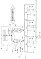
図2は、非接触給電装置1の移動体99の側の詳細な回路構成を示した回路図である。図示されるように、受電回路5は、受電コイル41ごとに設けられた整流回路51、および、2個の整流回路51に対して共通に設けられた直流電源回路55を含んで構成されている。
FIG. 2 is a circuit diagram illustrating a detailed circuit configuration on the moving
整流回路51は、4個の整流ダイオードをブリッジ接続した全波整流回路52、および全波整流回路52の出力側に接続された平滑コンデンサ53によって構成される。2個の整流回路51は、それぞれの入力側に接続された受電コイル41が非接触給電により受け取った交流電力を直流電圧Vdcに変換して出力する。2個の整流回路51の出力側の一端子513および他端子514は、直流電源回路55に対して並列接続されている。したがって、2個の整流回路51からそれぞれ出力される直流電圧Vdcが一つにまとめられて直流電源回路55に入力される。
The
直流電源回路55は、一つにまとめられた直流電圧Vdcを駆動電圧Vactに変換して電気負荷6に出力する変換回路の一実施形態である。直流電源回路55は、駆動電圧Vactの安定化作用を有する。つまり、直流電源回路55は、整流回路51から出力された電圧値不定の直流電圧Vdcを概ね一定の直流の駆動電圧Vactに調整して、移動体99に搭載された電気負荷6に給電する。直流電源回路55として、スイッチング方式またはドロッパ方式のDCDCコンバータを例示できる。直流電源回路55は、降圧機能を具備しており、さらに昇圧機能を具備していてもよい。電気負荷6は、移動体99上で仕事を行うものであり、その種類や消費電力などは限定されない。電気負荷6は、移動体99の移動用駆動源、例えばステッピングモータやサーボモータなどを含んでいてもよい。
The DC
電圧検出回路7は、直流電源回路55の入力側に並列接続されている。電圧検出回路7は、一つにまとめられた直流電圧Vdcを検出して監視する。例えば、電圧検出回路7は、直流電圧Vdcの大きさを検出してディジタル電圧値に変換するAD変換器と、ディジタル電圧値に所定の監視処理を施す電子制御装置と、を組み合わせて構成できる。また例えば、電圧検出回路7は、直流電圧Vdcを所定の基準電圧と大小比較する比較回路と、直流電圧Vdcが基準電圧以上となったときに所定の制御処理を実行する制御回路と、を組み合わせて構成できる。
The
電圧検出回路7の監視機能は、特に限定されず、直流電圧Vdcの上下限監視機能や、上限のみの監視機能、下限のみの監視機能などを採用できる。例えば、電圧検出回路7は、直流電圧Vdcが所定の基準電圧以上を超過したときに、直流電源回路55を停止して保護する機能を具備できる。また例えば、電圧検出回路7は、無線通信を介して基板生産機91、92、93の側の交流電源2に停止指令や調整指令を送信するようにしてもよい。これによれば、直流電圧Vdcが正常電圧範囲を逸脱したときに、交流電源2を停止させ、あるいは交流電源2の電圧値や周波数などを調整することができる。
The monitoring function of the
(2.第1実施形態の非接触給電装置1の作用)
次に、第1実施形態の非接触給電装置1の作用について、従来技術と比較して説明する。図3は、従来技術の非接触給電装置1Xの構成を模式的に説明する図である。従来技術の非接触給電装置1Xにおいて、固定部に相当する基板生産ライン9の側の構成は、第1実施形態と同じであり、移動体99の側の構成が第1実施形態と異なる。
(2. Operation of the non-contact power feeding device 1 of the first embodiment)
Next, the operation of the non-contact power feeding device 1 of the first embodiment will be described in comparison with the prior art. FIG. 3 is a diagram schematically illustrating the configuration of a conventional non-contact
従来技術の非接触給電装置1Xでは、2組の受電コイル41および整流回路51に対して、それぞれ直流電源回路55Xが設けられる。2個の直流電源回路55Xは、出力側の同じ大きさの駆動電圧Vactを一つにまとめて、電気負荷6に出力する。また、2個の直流電源回路55Xの入力側に、それぞれ電圧検出回路7Xが並列接続される。
In the conventional contactless power supply device 1 </ b> X, a DC
図1と図3を比較すれば明らかなように、第1実施形態では、従来技術で2個用いていた直流電源回路55Xおよび電圧検出回路7Xをそれぞれ1個に削減できる。
As is apparent from a comparison between FIG. 1 and FIG. 3, in the first embodiment, two DC
(3.第1実施形態の非接触給電装置1の態様および効果)
第1実施形態の非接触給電装置1は、固定部(基板生産ライン9)に設定された移動方向に沿って配置される複数(2個)の給電コイル31と、複数の給電コイル31に交流電力を供給する交流電源2と、移動方向に沿って移動する移動体99上に移動方向に沿って配置され、複数の給電コイル31のうち対向するいずれかの給電コイル31と電気的に結合して非接触で交流電力を受け取る複数(2個)の受電コイル41と、複数の受電コイル41が受け取った交流電力をそれぞれ直流電圧Vdcに変換して出力する複数(2個)の整流回路51と、記複数の整流回路51からそれぞれ出力される直流電圧Vdcが一つにまとめられて入力され、一つにまとめられた直流電圧Vdcを駆動電圧Vactに変換して電気負荷6に出力する変換回路(直流電源回路55X)と、一つにまとめられた直流電圧Vdcを検出して監視する電圧検出回路7と、を備えた。
(3. Aspects and effects of the non-contact power feeding device 1 of the first embodiment)
The non-contact power feeding device 1 according to the first embodiment includes a plurality (two) of power feeding coils 31 arranged along a moving direction set in a fixed portion (substrate production line 9), and a plurality of power feeding coils 31 with AC. The
第1実施形態の非接触給電装置1は、複数組の受電コイル41および整流回路51に対して共通な電圧検出回路7を用いて保護機能を高めるので、複数組に対して個別の電圧検出回路を用いる構成よりも簡素となる。また、移動体99に複数の受電コイル41を備えており、移動体99の位置に関係なく常に、少なくとも1個の受電コイル41が良好な受電状態となる。このため、移動体99に従来設けられていた充電回路およびバッテリを不要化して、直接的に電気負荷6を駆動できる。これらにより、移動体99の小形軽量化が実現される。
The contactless power supply device 1 according to the first embodiment uses the
さらに、第1実施形態の非接触給電装置1において、受電素子は受電コイル31であり、給電素子は給電コイル41とされている。また、第1実施形態の非接触給電装置1は、給電コイル31に接続されて給電側共振回路を形成する給電側コンデンサ35、および、受電コイル31に接続されて受電側共振回路を形成する受電側コンデンサ45をさらに備えている。これらによれば、電磁結合方式の非接触給電装置1において、共振現象を利用した非接触給電を行って顕著に給電効率を高めることができる。
Furthermore, in the non-contact power feeding device 1 of the first embodiment, the power receiving element is the
さらに、固定部は、複数(3台)の基板生産機91〜93が列設された基板生産ライン9であり、複数の基板生産機91〜93の列設方向に移動方向が設定されており、複数の給電コイル31は、複数の基板生産機91〜93に同数個ずつ配置されている。
Further, the fixed part is a
これによれば、第1〜第3基板生産機91、92、93の列設位置の順序変更、およびモジュール化された他の基板生産機との入れ替え、ならびに、列設台数が4台以上に増設されるモジュール増設対応の全ての場合に、非接触給電装置1は、良好な受電状態が確保される。したがって、基板生産ライン9のライン構成の変更時やモジュール増設対応時に、非接触給電装置1に関する段取り替え作業は簡素である。
According to this, the order of the arrangement positions of the first to third
(4.第2実施形態の非接触給電装置1A)
次に、第2実施形態の非接触給電装置1Aについて、第1実施形態と異なる点を主に説明する。第2実施形態において、固定部に相当する基板生産ライン9の側の構成が第1実施形態と異なり、移動体99の側の構成は第1実施形態と同じである。図4は、第2実施形態の非接触給電装置1Aの構成を模式的に説明する図である。
(4. Non-contact
Next, the non-contact
図示されるように、交流電源25は、複数の給電コイル31に対して共通に設けられている。交流電源25の電源容量は、第1実施形態の交流電源2の電源容量よりも大きい。交流電源25と、第1〜第3基板生産機91、92、93の各給電コイル31とを並列接続する電路には、それぞれ開閉スイッチ26が介挿されている。非接触給電装置1Aが動作している間、交流電源25は動作し続ける。そして、各基板生産機91、92、93の開閉スイッチ26は、図略のセンサによって移動体99の接近が検出されたときだけ閉路操作される。これにより、移動体99が遠方に離隔している間、給電コイル31は励磁されず、無駄な電気損失が発生しない。
As illustrated, the
第2実施形態の非接触給電装置1Aにおける作用は、第1実施形態と同じである。したがって、第2実施形態においても、共通な電圧検出回路7を用いて保護機能を高めることができ、かつ、充電回路およびバッテリを不要化できる。これにより、移動体99の小形軽量化が実現される。
The operation of the non-contact
(5.実施形態の応用および変形)
なお、共振用素子としての給電側コンデンサ35および受電側コンデンサ45を用いつつ、交流電源2、25の周波数を共振周波数からずらしてもよい。この場合、共振特性の変化の影響を受けにくくなるので、直流電圧Vdcの絶対値は多少低下しても、電圧変動は減少する。さらに、非接触給電の方式は、給電コイル31および受電コイル41を用いた電磁結合方式に限定されず、例えば、給電電極および受電電極を用いた静電結合方式であってもよい。本発明は、その他にも様々な応用や変形が可能である。
(5. Application and modification of embodiment)
Note that the frequency of the
本発明の非接触給電装置は、実施形態で説明した基板生産ライン9以外にも、他の製品を生産する組立ラインや加工ライン、電動車両の走行中給電など幅広い分野に利用可能である。
In addition to the
1、1A:非接触給電装置
2:交流電源 25:交流電源 26:開閉スイッチ
31:給電コイル(給電素子)
35:給電側コンデンサ(共振用素子)
41:受電コイル(受電素子)
45:受電側コンデンサ(共振用素子)
51:整流回路 55:直流電源回路(変換回路)
6:電気負荷
7:電圧検出回路
9:基板生産ライン(固定部)
91〜93:第1〜第3基板生産機 99:移動体
1, 1A: Non-contact power supply device 2: AC power supply 25: AC power supply 26: Open / close switch 31: Power supply coil (power supply element)
35: Power supply side capacitor (resonance element)
41: Power receiving coil (power receiving element)
45: Power receiving side capacitor (resonance element)
51: Rectifier circuit 55: DC power supply circuit (conversion circuit)
6: Electric load 7: Voltage detection circuit 9: Board production line (fixed part)
91-93: 1st-3rd board production machine 99: Mobile
Claims (4)
前記複数の給電素子に交流電力を供給する交流電源と、
前記移動方向に沿って移動する移動体上に前記移動方向に沿って配置され、前記複数の給電素子のうち対向するいずれかの給電素子と電気的に結合して非接触で交流電力を受け取る複数の受電素子と、
前記複数の受電素子が受け取った交流電力をそれぞれ直流電圧に変換して出力する複数の整流回路と、
前記複数の整流回路からそれぞれ出力される直流電圧が一つにまとめられて入力され、前記一つにまとめられた直流電圧を駆動電圧に変換して電気負荷に出力する変換回路と、
前記一つにまとめられた直流電圧を検出して監視する電圧検出回路と、
を備えた非接触給電装置。 A plurality of feeding elements arranged along the moving direction set in the fixed part;
AC power supply for supplying AC power to the plurality of power feeding elements,
A plurality of units that are arranged along the moving direction on a moving body that moves along the moving direction, and that are electrically coupled to one of the opposing feeding elements among the plurality of feeding elements and receive AC power in a non-contact manner. Power receiving elements,
A plurality of rectifier circuits that convert the AC power received by the plurality of power receiving elements into DC voltages, respectively, and output them,
DC voltage output from each of the plurality of rectifier circuits is integrated and input, a conversion circuit that converts the combined DC voltage into a drive voltage and outputs it to an electrical load;
A voltage detection circuit for detecting and monitoring the DC voltage combined into the one;
The non-contact electric power feeder provided with.
前記複数の給電素子は、前記複数の基板生産機に同数個ずつ配置されている請求項1〜3のいずれか一項に記載の非接触給電装置。 The fixing unit is a substrate production line in which a plurality of substrate production machines are arranged, and the moving direction is set in the arrangement direction of the plurality of substrate production machines,
The contactless power feeding device according to any one of claims 1 to 3, wherein the same number of the plurality of power feeding elements are arranged in each of the plurality of board production machines.
Priority Applications (1)
| Application Number | Priority Date | Filing Date | Title |
|---|---|---|---|
| JP2016027934A JP6677523B2 (en) | 2016-02-17 | 2016-02-17 | Wireless power supply |
Applications Claiming Priority (1)
| Application Number | Priority Date | Filing Date | Title |
|---|---|---|---|
| JP2016027934A JP6677523B2 (en) | 2016-02-17 | 2016-02-17 | Wireless power supply |
Publications (2)
| Publication Number | Publication Date |
|---|---|
| JP2017147848A true JP2017147848A (en) | 2017-08-24 |
| JP6677523B2 JP6677523B2 (en) | 2020-04-08 |
Family
ID=59682384
Family Applications (1)
| Application Number | Title | Priority Date | Filing Date |
|---|---|---|---|
| JP2016027934A Active JP6677523B2 (en) | 2016-02-17 | 2016-02-17 | Wireless power supply |
Country Status (1)
| Country | Link |
|---|---|
| JP (1) | JP6677523B2 (en) |
Citations (9)
| Publication number | Priority date | Publication date | Assignee | Title |
|---|---|---|---|---|
| JPH0666201U (en) * | 1993-02-23 | 1994-09-16 | 株式会社椿本チエイン | Non-contact power supply device for moving body on constant track |
| JPH1051982A (en) * | 1996-07-29 | 1998-02-20 | Hitachi Kiden Kogyo Ltd | Non-contacting feeding device |
| JPH118903A (en) * | 1997-06-16 | 1999-01-12 | Hitachi Kiden Kogyo Ltd | Non-contact power supply facility for moving body |
| JP2001112104A (en) * | 1999-10-08 | 2001-04-20 | Mitsubishi Electric Corp | Noncontact power feeding apparatus for mobile unit |
| JP2002354712A (en) * | 2001-05-22 | 2002-12-06 | Shinko Electric Co Ltd | Noncontact power feeder device |
| JP2010093902A (en) * | 2008-10-06 | 2010-04-22 | Nippon Tekumo:Kk | Noncontact power supply device |
| US20110198176A1 (en) * | 2008-07-04 | 2011-08-18 | Bombardier Transportation Gmbh | Transferring Electric Energy to a Vehicle |
| JP2011167031A (en) * | 2010-02-15 | 2011-08-25 | Toyota Central R&D Labs Inc | Power supplying device for moving body |
| WO2014049750A1 (en) * | 2012-09-26 | 2014-04-03 | 富士機械製造株式会社 | Electrostatic-coupling-type non-contact power supply apparatus |
-
2016
- 2016-02-17 JP JP2016027934A patent/JP6677523B2/en active Active
Patent Citations (10)
| Publication number | Priority date | Publication date | Assignee | Title |
|---|---|---|---|---|
| JPH0666201U (en) * | 1993-02-23 | 1994-09-16 | 株式会社椿本チエイン | Non-contact power supply device for moving body on constant track |
| JPH1051982A (en) * | 1996-07-29 | 1998-02-20 | Hitachi Kiden Kogyo Ltd | Non-contacting feeding device |
| JPH118903A (en) * | 1997-06-16 | 1999-01-12 | Hitachi Kiden Kogyo Ltd | Non-contact power supply facility for moving body |
| JP2001112104A (en) * | 1999-10-08 | 2001-04-20 | Mitsubishi Electric Corp | Noncontact power feeding apparatus for mobile unit |
| JP2002354712A (en) * | 2001-05-22 | 2002-12-06 | Shinko Electric Co Ltd | Noncontact power feeder device |
| US20110198176A1 (en) * | 2008-07-04 | 2011-08-18 | Bombardier Transportation Gmbh | Transferring Electric Energy to a Vehicle |
| JP2010093902A (en) * | 2008-10-06 | 2010-04-22 | Nippon Tekumo:Kk | Noncontact power supply device |
| JP2011167031A (en) * | 2010-02-15 | 2011-08-25 | Toyota Central R&D Labs Inc | Power supplying device for moving body |
| WO2014049750A1 (en) * | 2012-09-26 | 2014-04-03 | 富士機械製造株式会社 | Electrostatic-coupling-type non-contact power supply apparatus |
| US20150249366A1 (en) * | 2012-09-26 | 2015-09-03 | Fuji Machine Mfg Co., Ltd. | Electrostatic-coupling contactless power supply device |
Also Published As
| Publication number | Publication date |
|---|---|
| JP6677523B2 (en) | 2020-04-08 |
Similar Documents
| Publication | Publication Date | Title |
|---|---|---|
| JP6616422B2 (en) | Non-contact power feeding device | |
| JPWO2017051460A1 (en) | Non-contact power supply coil and non-contact power supply system | |
| JP6095661B2 (en) | Non-contact power feeding device | |
| JP6104254B2 (en) | Non-contact power feeding device | |
| JP6076355B2 (en) | Non-contact power feeding device | |
| JP6049744B2 (en) | Non-contact power feeding device | |
| JP6709804B2 (en) | Contactless power supply | |
| JP6701231B2 (en) | Contactless power supply | |
| JP6677523B2 (en) | Wireless power supply | |
| JP6678730B2 (en) | Wireless power supply | |
| JP6086927B2 (en) | Electrostatic coupling type non-contact power supply device | |
| JP6058003B2 (en) | Electrostatic coupling type non-contact power feeding device | |
| JP7162054B2 (en) | Contactless power supply system | |
| JP6873212B2 (en) | Board production line | |
| JPWO2016016930A1 (en) | Non-contact power feeding device |
Legal Events
| Date | Code | Title | Description |
|---|---|---|---|
| A621 | Written request for application examination |
Free format text: JAPANESE INTERMEDIATE CODE: A621 Effective date: 20181220 |
|
| A977 | Report on retrieval |
Free format text: JAPANESE INTERMEDIATE CODE: A971007 Effective date: 20190910 |
|
| A131 | Notification of reasons for refusal |
Free format text: JAPANESE INTERMEDIATE CODE: A131 Effective date: 20190917 |
|
| A521 | Request for written amendment filed |
Free format text: JAPANESE INTERMEDIATE CODE: A523 Effective date: 20191111 |
|
| A02 | Decision of refusal |
Free format text: JAPANESE INTERMEDIATE CODE: A02 Effective date: 20191126 |
|
| A521 | Request for written amendment filed |
Free format text: JAPANESE INTERMEDIATE CODE: A523 Effective date: 20200212 |
|
| A911 | Transfer to examiner for re-examination before appeal (zenchi) |
Free format text: JAPANESE INTERMEDIATE CODE: A911 Effective date: 20200219 |
|
| TRDD | Decision of grant or rejection written | ||
| A01 | Written decision to grant a patent or to grant a registration (utility model) |
Free format text: JAPANESE INTERMEDIATE CODE: A01 Effective date: 20200310 |
|
| A61 | First payment of annual fees (during grant procedure) |
Free format text: JAPANESE INTERMEDIATE CODE: A61 Effective date: 20200313 |
|
| R150 | Certificate of patent or registration of utility model |
Ref document number: 6677523 Country of ref document: JP Free format text: JAPANESE INTERMEDIATE CODE: R150 |
|
| R250 | Receipt of annual fees |
Free format text: JAPANESE INTERMEDIATE CODE: R250 |
|
| R250 | Receipt of annual fees |
Free format text: JAPANESE INTERMEDIATE CODE: R250 |