JP2017028362A - Transmission reception device - Google Patents

Transmission reception device Download PDF

Info

Publication number
JP2017028362A
JP2017028362A JP2015142058A JP2015142058A JP2017028362A JP 2017028362 A JP2017028362 A JP 2017028362A JP 2015142058 A JP2015142058 A JP 2015142058A JP 2015142058 A JP2015142058 A JP 2015142058A JP 2017028362 A JP2017028362 A JP 2017028362A
Authority
JP
Japan
Prior art keywords
signal
unit
self
wraparound
replica
Prior art date
Legal status (The legal status is an assumption and is not a legal conclusion. Google has not performed a legal analysis and makes no representation as to the accuracy of the status listed.)
Granted
Application number
JP2015142058A
Other languages
Japanese (ja)
Other versions
JP6367159B2 (en
Inventor
貴之 山田
Takayuki Yamada
貴之 山田
貴奈 加保
Takana Kaho
貴奈 加保
陽 山口
Akira Yamaguchi
陽 山口
匡夫 中川
Tadao Nakagawa
匡夫 中川
隆利 杉山
Takatoshi Sugiyama
隆利 杉山
Current Assignee (The listed assignees may be inaccurate. Google has not performed a legal analysis and makes no representation or warranty as to the accuracy of the list.)
Nippon Telegraph and Telephone Corp
Original Assignee
Nippon Telegraph and Telephone Corp
Priority date (The priority date is an assumption and is not a legal conclusion. Google has not performed a legal analysis and makes no representation as to the accuracy of the date listed.)
Filing date
Publication date
Application filed by Nippon Telegraph and Telephone Corp filed Critical Nippon Telegraph and Telephone Corp
Priority to JP2015142058A priority Critical patent/JP6367159B2/en
Publication of JP2017028362A publication Critical patent/JP2017028362A/en
Application granted granted Critical
Publication of JP6367159B2 publication Critical patent/JP6367159B2/en
Active legal-status Critical Current
Anticipated expiration legal-status Critical

Links

Images

Landscapes

  • Transceivers (AREA)

Abstract

PROBLEM TO BE SOLVED: To provide a transmission reception device which can improve a removal performance of a self-interference signal even when receiving random time fluctuation of a sneak self-interference signal.SOLUTION: A transmission reception device 150 that simultaneously sends and receives radio wave at the same frequency bandwidth comprises: a replica generation unit 15 which generates a replica signal of a transmitter signal using the transmitter signal that the transmission reception device sends; a feedback unit 70 which generates a feedback signal; a detector which detects a time when a sneak self-interference signal arrives using an input signal; a controller 80 which acquires difference information between the feedback signal and the sneak self-interference signal to control the replica generation unit by using the acquired difference information and the detected time; a cancel unit 90 which removes the sneak self-interference signal from the input signal using the feedback signal on the basis of the detected time; and a determination unit 81 which compares a residual component of the sneak self-interference signal left in the input signal with a threshold value to determine whether the sneak self-interference signal is removed from the input signal or not.SELECTED DRAWING: Figure 1

Description

本発明は、同一周波数帯域で電波の同時送受信を行う送受信機に関する。   The present invention relates to a transceiver that performs simultaneous transmission and reception of radio waves in the same frequency band.

近年、携帯電話や無線LANなどの無線通信システムの発展に伴い、周波数需要が増大しており、周波数利用効率の向上を図るため、同一周波数を用いて同時送受信を行う技術が提案されている。   In recent years, with the development of wireless communication systems such as mobile phones and wireless LANs, frequency demand has increased, and in order to improve frequency utilization efficiency, a technique for performing simultaneous transmission and reception using the same frequency has been proposed.

当該技術では、受信アンテナが、非常に電力が高く回り込んできた送信信号(以下、回り込み自干渉信号とも称される)を受信するため、回り込み自干渉信号を高い精度で除去する必要がある。例えば、既知の送信信号を用いて、回り込み自干渉信号のタイミング、振幅、位相を推定し、送信信号を送受信機内で分岐させ、回り込み自干渉信号とタイミングを合わせる遅延器と、同一レベルに調整する減衰器と、位相を合わせる移相器と、合波器とを用いて逆相合成し、回り込み自干渉信号を除去する技術が提案されている(例えば、非特許文献1、2参照)。   In this technique, the reception antenna receives a transmission signal (hereinafter also referred to as a wraparound self-interference signal) that has wrapped around with a very high power, and thus it is necessary to remove the wraparound self-interference signal with high accuracy. For example, using a known transmission signal, the timing, amplitude, and phase of the wraparound self-interference signal are estimated, the transmission signal is branched in the transmitter / receiver, and adjusted to the same level as the delay unit that matches the timing with the wraparound self-interference signal. Techniques have been proposed in which anti-phase synthesis is performed using an attenuator, a phase shifter for phase matching, and a multiplexer to remove a wraparound self-interference signal (see, for example, Non-Patent Documents 1 and 2).

また、既知の送信信号を用いて、回り込み自干渉信号のタイミングやチャネル特性を推定し、同一構成の送信処理部を別途用意してプリディストーション技術により回り込み自干渉信号を生成し、逆相合成することで回り込み自干渉信号を除去する技術が提案されている(例えば、非特許文献3参照)。   Also, using known transmission signals, the timing and channel characteristics of the sneaking self-interference signal are estimated, a separate transmission processing unit with the same configuration is prepared separately, and the sneaking self-interference signal is generated by the predistortion technique, and the anti-phase synthesis is performed. Thus, a technique for removing the sneaking self-interference signal has been proposed (see, for example, Non-Patent Document 3).

D. Korpi, et. al., "Widely Linear Digital Self-Interference Cancellation in Direct-Conversion Full-Duplex Transceiver", IEEE Journal on Selected Areas in Communications, vol.32, no.9, pp.1674-1687, Sept. 2014D. Korpi, et. Al., "Widely Linear Digital Self-Interference Cancellation in Direct-Conversion Full-Duplex Transceiver", IEEE Journal on Selected Areas in Communications, vol.32, no.9, pp.1674-1687, Sept . 2014 V. Syrjala, et. al., "Analysis of oscillator phase-noise effects on self-interference cancellation in full-duplex OFDM radio transceivers", IEEE Transactions on Wireless Communications, vol.13, no.6, pp.2977-2990, June 2014V. Syrjala, et. Al., "Analysis of oscillator phase-noise effects on self-interference cancellation in full-duplex OFDM radio transceivers", IEEE Transactions on Wireless Communications, vol.13, no.6, pp.2977-2990 , June 2014 R. Askar, et. al., "Active self-interference cancellation mechanism for full-duplex wireless transceivers", 9th International Conference on Cognitive Radio Oriented Wireless Networks and Communications (CROWNCOM) 2014. pp.539-544, June 2014R. Askar, et. Al., "Active self-interference cancellation mechanism for full-duplex wireless transceivers", 9th International Conference on Cognitive Radio Oriented Wireless Networks and Communications (CROWNCOM) 2014. pp.539-544, June 2014

しかしながら、非特許文献1、2では、タイミング、振幅および位相を高精度に設定する必要があるが、回り込み自干渉信号が送受信回路内でランダム性のある時変動を受けた場合、推定誤差が大きくなり回り込み自干渉信号の残留成分が重畳されたままとなるという問題がある。   However, in Non-Patent Documents 1 and 2, it is necessary to set the timing, amplitude, and phase with high precision. However, if the sneaking self-interference signal undergoes random fluctuations in the transmission / reception circuit, the estimation error is large. There is a problem that the residual component of the self-interference signal that is sneaking around remains superimposed.

また、非特許文献3では、プリディストーション技術を用いて回り込み自干渉信号を生成するため、パラメータ推定した時刻とキャンセル処理を行う時刻の間に時間差があり、推定後に時変動を受けると誤差が大きくなるという問題がある。   Further, in Non-Patent Document 3, since a self-interference signal is generated by using a predistortion technique, there is a time difference between the time when the parameter is estimated and the time when the canceling process is performed. There is a problem of becoming.

本発明は、回り込み自干渉信号が送受信機内でランダム性のある時変動を受ける場合でも、受信信号から回り込み自干渉信号を除去する信号を高い精度で生成でき、除去性能の向上を図ることができる送受信機を提供することを目的とする。   The present invention can generate a signal for removing a wraparound self-interference signal from a received signal with high accuracy even when the wraparound self-interference signal is subject to random fluctuations in the transceiver, and can improve the removal performance. An object is to provide a transceiver.

第1の発明は、同一周波数帯域で電波の同時送受信を行う送受信機であって、送受信機が送信する送信信号を用いて送信信号のレプリカであるレプリカ信号を生成する第1生成部と、送受信機が受信する受信信号に対して実行する受信処理を、送信信号のレプリカ信号に対して実行し、フィードバック信号を生成するフィードバック部と、受信信号に含まれる信号のうち自装置の送信信号が回り込んだ回り込み自干渉信号の到来した時刻を、受信信号を用いて検出する検出部と、フィードバック信号と回り込み自干渉信号とを比較し、フィードバック信号と回り込み自干渉信号との間の振幅および位相の差を示す差分情報を求め、求めた差分情報と検出された時刻とを用いて第1生成部を制御する制御部と、検出された時刻に基づいて、フィードバック信号を回り込み自干渉信号のレプリカ信号として用いて受信信号から回り込み自干渉信号を除去するキャンセル部と、回り込み自干渉信号が除去された受信信号に残留する回り込み自干渉信号の残留成分と閾値とを比較し、キャンセル部から出力される受信信号から回り込み自干渉信号が除去されたか否かを判定する判定部とを備えることを特徴とする。   A first invention is a transmitter / receiver that performs simultaneous transmission / reception of radio waves in the same frequency band, and a first generation unit that generates a replica signal that is a replica of a transmission signal using a transmission signal transmitted by the transmitter / receiver, and transmission / reception A reception process performed on the received signal received by the machine is performed on the replica signal of the transmission signal, and a feedback unit that generates a feedback signal and a transmission signal of the own device among the signals included in the reception signal are rotated. The detection unit that detects the arrival time of the wraparound self-interference signal using the received signal, the feedback signal and the wraparound self-interference signal are compared, and the amplitude and phase between the feedback signal and the wraparound self-interference signal are compared. Difference information indicating a difference is obtained, and a control unit that controls the first generation unit using the obtained difference information and the detected time, and a process based on the detected time. A cancellation unit that removes the wraparound self-interference signal from the received signal using the back signal as a replica signal of the wraparound self-interference signal, and a residual component and threshold value of the wraparound self-interference signal remaining in the received signal from which the wraparound self-interference signal is removed And a determination unit that determines whether or not the self-interference signal has been removed from the reception signal output from the cancel unit.

第2の発明は、第1生成部は、検出された時刻に基づくタイミングで、差分情報を用いて送信信号のレプリカ信号から回り込み自干渉信号のレプリカ信号を生成し、キャンセル部は、第1生成部により生成された回り込み自干渉信号のレプリカ信号を用いて受信信号から回り込み自干渉信号を除去することを特徴とする。   In the second aspect of the invention, the first generation unit generates a replica signal of the self-interference signal from the replica signal of the transmission signal using the difference information at a timing based on the detected time, and the cancellation unit generates the first generation signal. The self-interference signal is removed from the received signal using the replica signal of the self-interference signal generated by the unit.

第3の発明は、差分情報を用いて送信信号のレプリカ信号から回り込み自干渉信号のレプリカ信号を生成する少なくとも1以上の第2生成部を備え、検出部は、受信信号に含まれる回り込み自干渉信号の到来した時刻を第2生成部の数に応じて検出し、制御部は、検出された時刻に基づくタイミングで、第2生成部に回り込み自干渉信号のレプリカ信号を生成させ、キャンセル部は、第2生成部により生成された回り込み自干渉信号のレプリカ信号を用いて受信信号から回り込み自干渉信号を除去することを特徴とする。   A third invention includes at least one second generation unit that generates a replica signal of a wraparound self-interference signal from a replica signal of a transmission signal using difference information, and the detection unit includes a wraparound self-interference included in the received signal. The time at which the signal arrives is detected according to the number of second generation units, and the control unit causes the second generation unit to generate a replica signal of the self-interference signal at a timing based on the detected time, and the cancellation unit The wraparound self-interference signal is removed from the received signal using the replica signal of the wraparound self-interference signal generated by the second generation unit.

第4の発明は、送信信号の時変動成分を抽出する抽出部を備え、第1生成部は、抽出した時変動成分を用いて送信信号のレプリカ信号を生成することを特徴とする。   According to a fourth aspect of the invention, an extraction unit that extracts a time-varying component of a transmission signal is provided, and the first generation unit generates a replica signal of the transmission signal using the extracted time-varying component.

第5の発明は、同一周波数帯域で電波の同時送受信を行う送受信機であって、送受信機が送信する送信信号を用いて送信信号のレプリカであるレプリカ信号を生成する第1生成部と、送受信機が受信する受信信号に対して実行する受信処理のうち一部の処理が除外された処理を、送信信号のレプリカ信号に対して実行し、フィードバック信号を生成するフィードバック部と、送受信機が受信する受信信号の時変動成分のうち、除外された一部の処理に対応する時変動成分を抽出する抽出部と、受信信号に含まれる信号のうち自装置の送信信号が回り込んだ回り込み自干渉信号の到来した時刻を、受信信号を用いて検出する検出部と、フィードバック信号と抽出した時変動成分と検出した時刻とを用いて、参照信号を生成する第2生成部と、参照信号と回り込み自干渉信号とを比較し、参照信号と回り込み自干渉信号との間の振幅および位相の差を示す差分情報を求め、求めた差分情報を用いて参照信号から回り込み自干渉信号のレプリカであるレプリカ信号を生成する第3生成部と、検出された時刻に基づいて、回り込み自干渉信号のレプリカ信号を用いて受信信号から回り込み自干渉信号を除去するキャンセル部と、回り込み自干渉信号が除去された受信信号に残留する回り込み自干渉信号の残留成分と閾値とを比較し、キャンセル部から出力される受信信号から回り込み自干渉信号が除去されたか否かを判定する判定部とを備えることを特徴とする。   A fifth invention is a transmitter / receiver that performs simultaneous transmission / reception of radio waves in the same frequency band, and a first generation unit that generates a replica signal that is a replica of a transmission signal using a transmission signal transmitted by the transmitter / receiver, and transmission / reception A feedback unit that generates a feedback signal by executing a process that excludes a part of the reception process performed on the received signal received by the machine on the replica signal of the transmission signal, and the transceiver receives the received signal. An extraction unit that extracts time-varying components corresponding to some of the excluded processing from the time-varying component of the received signal, and wraparound self-interference in which the transmission signal of the own device wraps around the signal included in the received signal A detection unit that detects the arrival time of the signal using the received signal, a second generation unit that generates a reference signal using the feedback signal, the extracted time variation component, and the detected time; The signal and the wraparound self-interference signal are compared, difference information indicating a difference in amplitude and phase between the reference signal and the wraparound self-interference signal is obtained, and a replica of the wraparound self-interference signal is obtained from the reference signal using the obtained difference information. A third generation unit that generates a replica signal, a cancellation unit that removes a wraparound self-interference signal from a received signal using a replica signal of the wraparound self-interference signal based on the detected time, and a wraparound self-interference signal A determination unit that compares a residual component of the wraparound self-interference signal remaining in the removed received signal with a threshold value and determines whether or not the wraparound self-interference signal is removed from the reception signal output from the cancel unit; It is characterized by.

第6の発明は、送信信号の時変動成分を抽出する抽出部を備え、第1生成部は、抽出した時変動成分を用いて送信信号のレプリカ信号を生成することを特徴とする。   According to a sixth aspect of the invention, an extraction unit that extracts a time-varying component of a transmission signal is provided, and the first generation unit generates a replica signal of the transmission signal using the extracted time-varying component.

本発明は、回り込み自干渉信号が送受信機内でランダム性のある時変動を受ける場合でも、受信信号から回り込み自干渉信号を除去する信号を高い精度で生成でき、除去性能の向上を図ることができる。   The present invention can generate a signal for removing a wraparound self-interference signal from a received signal with high accuracy even when the wraparound self-interference signal is subject to random fluctuations in the transceiver, and can improve the removal performance. .

送受信機の一実施形態を示す図である。It is a figure which shows one Embodiment of a transmitter / receiver. 図1に示した送受信機における送受信処理の一例を示す図である。It is a figure which shows an example of the transmission / reception process in the transmitter / receiver shown in FIG. 送受信機の別の実施形態を示す図である。It is a figure which shows another embodiment of a transmitter / receiver. 図3に示した送受信機における送受信処理の一例を示す図である。It is a figure which shows an example of the transmission / reception process in the transmitter / receiver shown in FIG. 送受信機の別の実施形態を示す図である。It is a figure which shows another embodiment of a transmitter / receiver. 図5に示した送受信機における送受信処理の一例を示す図である。It is a figure which shows an example of the transmission / reception process in the transmitter / receiver shown in FIG. 送受信機の別の実施形態を示す図である。It is a figure which shows another embodiment of a transmitter / receiver. 図7に示した送受信機における送受信処理の一例を示す図である。It is a figure which shows an example of the transmission / reception process in the transmitter / receiver shown in FIG. 送受信機の別の実施形態を示す図である。It is a figure which shows another embodiment of a transmitter / receiver. 図9に示した送受信機における送受信処理の一例を示す図である。It is a figure which shows an example of the transmission / reception process in the transmitter / receiver shown in FIG. 送受信機の別の実施形態を示す図である。It is a figure which shows another embodiment of a transmitter / receiver. 送受信機の別の実施形態を示す図である。It is a figure which shows another embodiment of a transmitter / receiver. 送受信機の別の実施形態を示す図である。It is a figure which shows another embodiment of a transmitter / receiver.

以下、図面を用いて実施形態について説明する。   Hereinafter, embodiments will be described with reference to the drawings.

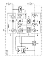
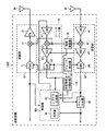
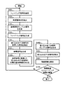
図1は、送受信機の一実施形態を示す。   FIG. 1 illustrates one embodiment of a transceiver.

図1に示した送受信機150は、送信部10、レプリカ生成部15、受信部40、局部発振器50、クロック発生器60、フィードバック部70、制御部80およびキャンセル部90を有する。   The transceiver 150 illustrated in FIG. 1 includes a transmission unit 10, a replica generation unit 15, a reception unit 40, a local oscillator 50, a clock generator 60, a feedback unit 70, a control unit 80, and a cancellation unit 90.

送信部10は、DAC(Digital to Analog Converter)11、ミキサ12およびPA(Power Amplifier)13を有する。また、送信部10は、送信アンテナ20に接続され、送信アンテナ20を介して送信信号を送信する。   The transmission unit 10 includes a DAC (Digital to Analog Converter) 11, a mixer 12, and a PA (Power Amplifier) 13. The transmission unit 10 is connected to the transmission antenna 20 and transmits a transmission signal via the transmission antenna 20.

DAC11は、送信部10に含まれる変調器によりQPSK(Quadrature Phase Shift Keying)等の変調方式で変調されたデータを含むデジタルの送信信号を、クロック発生器60が出力するクロック信号に基づきアナログの送信信号に変換する。   The DAC 11 performs analog transmission of a digital transmission signal including data modulated by a modulation method such as QPSK (Quadrature Phase Shift Keying) by a modulator included in the transmission unit 10 based on a clock signal output from the clock generator 60. Convert to signal.

ミキサ12は、データを含むアナログの送信信号(すなわち、ベースバンド信号)を、局部発振器50が出力するLO(Local)信号のRF(Radio Frequency)帯の周波数にアップコンバートする。   The mixer 12 up-converts an analog transmission signal (that is, a baseband signal) including data to an RF (Radio Frequency) band frequency of a LO (Local) signal output from the local oscillator 50.

PA13は、生成された送信信号の電力を増幅する。そして、送信部10は、送信信号を送信アンテナ20およびレプリカ生成部15にそれぞれ出力する。   The PA 13 amplifies the power of the generated transmission signal. Then, the transmission unit 10 outputs the transmission signal to the transmission antenna 20 and the replica generation unit 15, respectively.

レプリカ生成部15は、送信部10から受けた送信信号を用いて送信信号のレプリカであるレプリカ信号を生成する。すなわち、レプリカ生成部15は、送信部10から受けた送信信号を送信信号のレプリカ信号とする。レプリカ生成部15は、送信信号のレプリカ信号をフィードバック部70に出力する。   The replica generation unit 15 uses the transmission signal received from the transmission unit 10 to generate a replica signal that is a replica of the transmission signal. That is, the replica generation unit 15 sets the transmission signal received from the transmission unit 10 as a replica signal of the transmission signal. The replica generation unit 15 outputs a replica signal of the transmission signal to the feedback unit 70.

受信部40は、受信アンテナ30に接続され、受信アンテナ30を介して他の送受信機から送信された送信信号を受信する。また、送受信機150が同一周波数帯同時送受信を行うため、受信部40は、自装置の送信部10により送信された送信信号を、受信アンテナ30を介して受信する。以下、受信信号のうち、受信アンテナ30に回り込んだ自装置の送信信号は、回り込み自干渉信号とも称される。受信部40は、LNA(Low Noise Amplifier)41、ミキサ42、AGC(Automatic Gain Control)43およびADC(Analog to Digital Converter)44を有する。   The receiving unit 40 is connected to the receiving antenna 30 and receives a transmission signal transmitted from another transceiver via the receiving antenna 30. In addition, since the transmitter / receiver 150 performs simultaneous transmission / reception of the same frequency band, the reception unit 40 receives the transmission signal transmitted by the transmission unit 10 of its own device via the reception antenna 30. Hereinafter, of the received signals, the transmission signal of the own device that has sneak into the reception antenna 30 is also referred to as a sneak self-interference signal. The receiving unit 40 includes an LNA (Low Noise Amplifier) 41, a mixer 42, an AGC (Automatic Gain Control) 43, and an ADC (Analog to Digital Converter) 44.

LNA41は、低雑音の増幅器であり、受信アンテナ30を介して受信した受信信号を増幅する。   The LNA 41 is a low noise amplifier, and amplifies the reception signal received via the reception antenna 30.

ミキサ42は、局部発振器50が出力するLO信号を用いて、RF帯域の周波数からベースバンド信号の周波数にダウンコンバートする。ミキサ42は、ベースバンドの受信信号をAGC43に出力する。   The mixer 42 down-converts from the frequency of the RF band to the frequency of the baseband signal using the LO signal output from the local oscillator 50. The mixer 42 outputs a baseband received signal to the AGC 43.

AGC43は、受信したベースバンドの受信信号の電力が所定の範囲内となるように、受信信号の電力レベルを制御し、制御された受信信号をADC44に出力する。また、AGC43は、受信信号に対して実行した利得制御の内容を示す利得情報を含む信号を、後述するフィードバック部70に含まれるAGC43に出力する。   The AGC 43 controls the power level of the received signal so that the power of the received baseband received signal is within a predetermined range, and outputs the controlled received signal to the ADC 44. In addition, the AGC 43 outputs a signal including gain information indicating the content of gain control performed on the received signal to the AGC 43 included in the feedback unit 70 described later.

ADC44は、クロック発生器60が出力するクロック信号に基づきベースバンドの受信信号をデジタル信号に変換する。そして、受信部40は、デジタル信号に変換された受信信号を制御部80およびキャンセル部90にそれぞれ出力する。   The ADC 44 converts the baseband received signal into a digital signal based on the clock signal output from the clock generator 60. Then, the reception unit 40 outputs the reception signal converted into the digital signal to the control unit 80 and the cancellation unit 90, respectively.

なお、上述のベースバンドの各信号は、IF(Intermediate Frequency)帯の信号としてもよい(以降のベースバンドに対しても同様である)。   The baseband signals described above may be IF (Intermediate Frequency) band signals (the same applies to the subsequent basebands).

局部発振器50は、VCO(Voltage-Controlled Oscillator)等の発振器であり、印加される電圧に応じて発振周波数を制御することで、所定の周波数のLO信号を生成する。局部発振器50は、送信部10のミキサ12、受信部40のミキサ42およびフィードバック部70に含まれるミキサ42の各々に生成したLO信号を出力する。   The local oscillator 50 is an oscillator such as a VCO (Voltage-Controlled Oscillator), and generates an LO signal having a predetermined frequency by controlling an oscillation frequency according to an applied voltage. The local oscillator 50 outputs the generated LO signal to each of the mixer 12 of the transmission unit 10, the mixer 42 of the reception unit 40, and the mixer 42 included in the feedback unit 70.

クロック発生器60は、送信部10のDAC11、受信部40のADC44およびフィードバック部70に含まれるADC44を動作させるクロック信号を生成する。そして、クロック発生器60は、送信部10のDAC11、受信部40のADC44およびフィードバック部70のDAC44の各々に生成したクロック信号を出力する。   The clock generator 60 generates a clock signal that operates the DAC 11 of the transmission unit 10, the ADC 44 of the reception unit 40, and the ADC 44 included in the feedback unit 70. The clock generator 60 outputs the generated clock signal to each of the DAC 11 of the transmission unit 10, the ADC 44 of the reception unit 40, and the DAC 44 of the feedback unit 70.

フィードバック部70は、受信部40と同様に、LNA41、ミキサ42、AGC43およびADC44を有する。すなわち、フィードバック部70は、受信部40が受信する受信信号に対して実行するのと同じ受信処理を、レプリカ生成部15から受信した送信信号のレプリカ信号に対して実行する。フィードバック部70は、同じ受信処理が実行されたフィードバック信号(すなわち、回り込み自干渉信号のレプリカ信号)を生成する。フィードバック部70は、生成したフィードバック信号を制御部80およびキャンセル部90に出力する。   The feedback unit 70 includes an LNA 41, a mixer 42, an AGC 43, and an ADC 44, similar to the receiving unit 40. That is, the feedback unit 70 performs the same reception process as the reception signal received by the reception unit 40 on the replica signal of the transmission signal received from the replica generation unit 15. The feedback unit 70 generates a feedback signal (that is, a replica signal of the wraparound self-interference signal) that has been subjected to the same reception process. The feedback unit 70 outputs the generated feedback signal to the control unit 80 and the cancellation unit 90.

制御部80は、プロセッサ等であり、送受信機150に含まれるメモリ等の記憶装置に記憶されたプログラムを実行することで、送受信機150の各要素を制御する。   The control unit 80 is a processor or the like, and controls each element of the transceiver 150 by executing a program stored in a storage device such as a memory included in the transceiver 150.

制御部80は、受信部40から受信した受信信号を用いて、受信アンテナ30を介して自装置の送信信号が回り込んだ回り込み自干渉信号の到来した時刻を検出する。例えば、制御部80は、受信部40から受信した受信信号の電力と所定値とを比較し、所定値以上となった時刻を回り込み自干渉信号が到来した時刻として検出する。あるいは、制御部80は、フィードバック部70から受信したフィードバック信号と受信部40から受信した受信信号との相関処理を実行し、相関値がピークを示す時刻を回り込み自干渉信号が到来した時刻として検出してもよい。そして、制御部80は、例えば、送信部10が送信信号を送信してから受信部40が回り込み自干渉信号を受信するまでの送信信号の伝播時間を求める。伝搬時間は、例えば、使用するRFに応じて予め測定した送信部10および受信部40の各入出力間の通過時間の合計を、送信部10への入力時点から受信部40の出力時点の間の時間から差し引いた時間として算出される。   The control unit 80 uses the received signal received from the receiving unit 40 to detect the arrival time of the wraparound self-interference signal that the transmission signal of the own device wraps through the receiving antenna 30. For example, the control unit 80 compares the power of the reception signal received from the reception unit 40 with a predetermined value, and detects the time when the self-interference signal arrives at the time when the predetermined value is exceeded. Alternatively, the control unit 80 performs a correlation process between the feedback signal received from the feedback unit 70 and the received signal received from the receiving unit 40, and detects the time when the self-interference signal arrives around the time when the correlation value shows a peak. May be. Then, for example, the control unit 80 obtains the propagation time of the transmission signal from when the transmission unit 10 transmits the transmission signal until the reception unit 40 receives the self-interference signal. The propagation time is, for example, the sum of the passage times between the input and output of the transmission unit 10 and the reception unit 40 measured in advance according to the RF to be used, between the input time to the transmission unit 10 and the output time of the reception unit 40. It is calculated as the time subtracted from the time.

また、制御部80は、検出した時刻のタイミングで、フィードバック部70が生成したフィードバック信号と受信部40から受信した受信信号に含まれる回り込み自干渉信号とを比較する。制御部80は、フィードバック信号と回り込み自干渉信号との間の相対的な振幅および位相の差を示す差分情報を求める。そして、制御部80は、求めた差分情報と検出した時刻とを用いてレプリカ生成部15を制御する。例えば、制御部80は、伝播時間から求まる回り込み自干渉信号が到来する時刻のタイミングで、レプリカ生成部15に対し、差分情報を用いて振幅および位相を変化させた送信信号のレプリカ信号を生成させ、フィードバック部70に出力させる。これにより、フィードバック部70は、受信部40から出力される受信信号と同じ時変動を示すフィードバック信号を生成できる。   Further, the control unit 80 compares the feedback signal generated by the feedback unit 70 with the wraparound self-interference signal included in the reception signal received from the reception unit 40 at the timing of the detected time. The control unit 80 obtains difference information indicating a relative amplitude and phase difference between the feedback signal and the wraparound self-interference signal. Then, the control unit 80 controls the replica generation unit 15 using the obtained difference information and the detected time. For example, the control unit 80 causes the replica generation unit 15 to generate a replica signal of the transmission signal whose amplitude and phase are changed using the difference information at the time when the wraparound self-interference signal arrives from the propagation time. The feedback unit 70 outputs the output. Thereby, the feedback unit 70 can generate a feedback signal that shows the same time variation as the reception signal output from the reception unit 40.

なお、フィードバック部70のLNA41を省略して、LNA41による振幅および位相の変化量をレプリカ生成部15における振幅および位相の変化量に合算してもよい。   Note that the LNA 41 of the feedback unit 70 may be omitted, and the amplitude and phase changes due to the LNA 41 may be added to the amplitude and phase changes in the replica generation unit 15.

また、制御部80は、プログラムを実行することで、判定部81として動作する。判定部81は、キャンセル部90により回り込み自干渉信号が除去された受信信号において、受信信号に残留する回り込み自干渉信号の残量を、受信信号の電力から測定する。例えば、制御部80が回り込み自干渉信号の到来した時刻および差分情報を求めるトレーニング期間では、送受信機150は、所定のデータを含む送信信号(トレーニング信号)を送信する。すなわち、トレーニング期間では、送受信機150は、送信されたトレーニング信号の回り込み自干渉信号以外の信号を受信しない。このため、判定部81は、キャンセル部90から受信した受信信号、すなわち残留する回り込み自干渉信号の電力を残留誤差として測定できる。そして、判定部81は、測定した残留誤差の値がトレーニング期間の閾値以下か否かを判定する。なお、トレーニング期間の閾値は、制御部80がトレーニング期間に判定部81に設定する閾値であり、ノイズレベルと許容される残留する回り込み自干渉信号の電力とに基づいて設定される。   The control unit 80 operates as the determination unit 81 by executing a program. The determination unit 81 measures the remaining amount of the wraparound self-interference signal remaining in the reception signal from the power of the reception signal in the reception signal from which the wraparound self-interference signal has been removed by the cancellation unit 90. For example, in the training period in which the control unit 80 obtains the time of arrival of the sneaking self-interference signal and the difference information, the transceiver 150 transmits a transmission signal (training signal) including predetermined data. In other words, during the training period, the transceiver 150 does not receive any signals other than the transmitted self-interference signal of the training signal. Therefore, the determination unit 81 can measure the received signal received from the cancel unit 90, that is, the power of the remaining sneak self-interference signal as a residual error. Then, the determination unit 81 determines whether or not the measured residual error value is equal to or less than the training period threshold value. The threshold for the training period is a threshold set by the control unit 80 in the determination unit 81 during the training period, and is set based on the noise level and the allowable power of the remaining self-interference signal.

判定部81は、残留誤差の値がトレーニング期間の閾値以下の場合、回り込み自干渉信号がキャンセル部90で除去されたと判定する。この場合、制御部80は、検出された回り込み自干渉信号の到来した時刻、および到来した時刻から求めた伝播時間と差分情報とを、送受信機150の記憶装置に記憶する。一方、判定部81は、残留誤差の値がトレーニング期間の閾値より大きい場合、回り込み自干渉信号が受信信号から十分に除去されていないと判定する。この場合、制御部80は、回り込み自干渉信号が到来する時刻を、残留誤差の値が最小となるようにLMS(Least Mean Squares)アルゴリズム等の最適化アルゴリズムを実行して調整する。そして、制御部80は、残留誤差の値がトレーニング期間の閾値以下となる(すなわち、回り込み自干渉信号がキャンセル部90により除去される)まで繰り返し調整する。   The determination unit 81 determines that the wraparound self-interference signal has been removed by the cancel unit 90 when the residual error value is equal to or less than the training period threshold value. In this case, the control unit 80 stores in the storage device of the transceiver 150 the time when the detected sneak self-interference signal arrives and the propagation time and difference information obtained from the time of arrival. On the other hand, when the residual error value is larger than the training period threshold value, the determination unit 81 determines that the wraparound self-interference signal is not sufficiently removed from the received signal. In this case, the control unit 80 adjusts the time at which the wraparound self-interference signal arrives by executing an optimization algorithm such as an LMS (Least Mean Squares) algorithm so that the residual error value is minimized. Then, the control unit 80 repeatedly adjusts until the value of the residual error becomes equal to or less than the training period threshold (that is, the wraparound self-interference signal is removed by the cancel unit 90).

そして、制御部80は、トレーニング期間が終了した後、同時送受信の通常運用に移行する。制御部80は、トレーニング期間で求めた伝播時間から求まる回り込み自干渉信号が到来する時刻のタイミングで、送受信機150の記憶装置に保持した差分情報を用いてレプリカ生成部15の動作を随時制御する。   And the control part 80 transfers to normal operation of simultaneous transmission / reception after a training period is complete | finished. The control unit 80 controls the operation of the replica generation unit 15 at any time using the difference information held in the storage device of the transceiver 150 at the time when the wraparound self-interference signal arrives from the propagation time obtained in the training period. .

なお、制御部80は、通常運用の期間でも、判定部81に回り込み自干渉信号の残留誤差を測定させ、測定した残留誤差の値と通常運用の閾値とを比較し、残留誤差の値が通常運用の閾値より大きい場合、再度トレーニング期間に戻ってもよい。なお、通常運用の閾値は、制御部80が通常運用の期間に判定部81に設定する閾値であり、他の送受信機から受信する電力と許容される残留する回り込み自干渉信号の電力とに基づいて設定される。また、制御部80は、判定部81に残留誤差による判定の代わりに、他の送受信機から受信した受信信号のビット誤り率やパケット誤り率等の誤り率を測定させ、測定した誤り率が所定値より劣化した場合、トレーニング期間に戻るようにしてもよい。また、制御部80は、送受信機150が起動される度にトレーニング期間から開始するようにしてもよい。また、所定の周期でトレーニング期間に戻るようにしてもよい。   Note that, even during the normal operation period, the control unit 80 causes the determination unit 81 to measure the residual error of the self-interference signal, and compares the measured residual error value with the normal operation threshold value. If it is larger than the operation threshold, the training period may be resumed. The normal operation threshold is a threshold set by the control unit 80 in the determination unit 81 during the normal operation, and is based on the power received from other transceivers and the power of the remaining sneak self-interference signal allowed. Is set. In addition, the control unit 80 causes the determination unit 81 to measure an error rate such as a bit error rate or a packet error rate of a received signal received from another transmitter / receiver instead of the determination based on the residual error, and the measured error rate is predetermined. When it deteriorates from the value, it may be returned to the training period. Further, the control unit 80 may start from the training period every time the transceiver 150 is activated. Moreover, you may make it return to a training period with a predetermined period.

キャンセル部90は、フィードバック部70により生成されたフィードバック信号を回り込み自干渉信号のレプリカ信号として用いて、受信信号に含まれる回り込み自干渉信号を除去する。例えば、キャンセル部90は、回り込み自干渉信号が到来した時刻のタイミングで、回り込み自干渉信号のレプリカ信号を受信信号に逆位相で合成し、受信信号に含まれる回り込み自干渉信号を除去する。キャンセル部90は、回り込み自干渉信号が除去された受信信号を判定部81に出力する。また、送受信機150は、キャンセル部90により回り込み自干渉信号が除去された受信信号に対して復調処理を実行する。   The cancel unit 90 uses the feedback signal generated by the feedback unit 70 as a replica signal of the wraparound self-interference signal, and removes the wraparound self-interference signal included in the received signal. For example, the cancel unit 90 synthesizes the replica signal of the wraparound self-interference signal with the reception signal in the opposite phase at the time when the wraparound self-interference signal arrives, and removes the wraparound self-interference signal included in the reception signal. The cancel unit 90 outputs the received signal from which the wraparound self-interference signal has been removed to the determination unit 81. In addition, the transceiver 150 performs demodulation processing on the received signal from which the wraparound self-interference signal has been removed by the cancel unit 90.

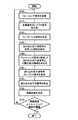
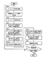
図2は、図1に示した送受信機150における送受信処理の一例を示す。図2に示した処理は、例えば、送受信機150に含まれるプロセッサ等の制御部80が記憶装置に記憶されるプログラムを実行することにより実現される。なお、図2に示した処理は、送受信機150に設けられるハードウェアにより実行されてもよい。この場合、図1に示した判定部81は、送受信機150内に配置される回路により実現される。   FIG. 2 shows an example of transmission / reception processing in the transceiver 150 shown in FIG. The processing illustrated in FIG. 2 is realized, for example, when a control unit 80 such as a processor included in the transceiver 150 executes a program stored in the storage device. 2 may be executed by hardware provided in the transceiver 150. In this case, the determination unit 81 illustrated in FIG. 1 is realized by a circuit disposed in the transceiver 150.

ステップS100では、送信部10は、トレーニング期間の場合、制御部80からの指示に基づいて、所定のデータを含んだトレーニング信号を、送信アンテナ20を介して送信する。また、送信部10は、トレーニング信号をレプリカ生成部15に出力する。   In step S <b> 100, the transmission unit 10 transmits a training signal including predetermined data via the transmission antenna 20 based on an instruction from the control unit 80 in the training period. In addition, the transmission unit 10 outputs the training signal to the replica generation unit 15.

ステップS110では、レプリカ生成部15は、送信部10から受けた送信信号(トレーニング信号)を用いて送信信号のレプリカ信号を生成する。すなわち、レプリカ生成部15は、送信部10から受けた送信信号を送信信号のレプリカ信号とし、送信信号のレプリカ信号をフィードバック部70に出力する。   In step S110, the replica generation unit 15 generates a replica signal of the transmission signal using the transmission signal (training signal) received from the transmission unit 10. That is, the replica generation unit 15 uses the transmission signal received from the transmission unit 10 as a replica signal of the transmission signal, and outputs the replica signal of the transmission signal to the feedback unit 70.

ステップS120では、フィードバック部70は、ステップS110で生成された送信信号のレプリカ信号に対して受信部40と同じ受信処理を実行し、フィードバック信号(すなわち、回り込み自干渉信号のレプリカ信号)を生成する。   In step S120, the feedback unit 70 performs the same reception process as that of the reception unit 40 on the replica signal of the transmission signal generated in step S110, and generates a feedback signal (that is, a replica signal of the wraparound self-interference signal). .

ステップS130では、制御部80は、受信部40が受信した受信信号を用いて、受信アンテナ30を介して送信信号が回り込んだ回り込み自干渉信号の到来した時刻を検出する。   In step S <b> 130, the control unit 80 uses the received signal received by the receiving unit 40 to detect the time at which the wraparound self-interference signal that the transmission signal wraps through the receiving antenna 30 arrives.

ステップS140では、制御部80は、ステップS130で生成されたフィードバック信号と受信部40から受信した受信信号に含まれる回り込み自干渉信号とを比較し、フィードバック信号と回り込み自干渉信号との間の相対的な振幅および位相の差を示す差分情報を求める。そして、制御部80は、ステップS130で検出した時刻と求めた差分情報とを用いて、レプリカ生成部15を制御する。   In step S140, the control unit 80 compares the feedback signal generated in step S130 with the wraparound self-interference signal included in the received signal received from the reception unit 40, and compares the relative between the feedback signal and the wraparound self-interference signal. Difference information indicating a difference between a typical amplitude and phase is obtained. And the control part 80 controls the replica production | generation part 15 using the time detected by step S130, and the calculated | required difference information.

ステップS150では、キャンセル部90は、ステップS120で生成されたフィードバック信号を回り込み自干渉信号のレプリカ信号として用いて、受信信号に含まれる回り込み自干渉信号を除去する。   In step S150, the cancel unit 90 uses the feedback signal generated in step S120 as a replica signal of the wraparound self-interference signal, and removes the wraparound self-interference signal included in the received signal.

ステップS160では、判定部81は、ステップS150で回り込み自干渉信号が除去された受信信号の電力を残留誤差として測定する。   In step S160, the determination unit 81 measures the power of the received signal from which the wraparound self-interference signal has been removed in step S150 as a residual error.

ステップS170では、判定部81は、ステップS160で測定した残留誤差の値がトレーニング期間の閾値以下か否かを判定する。判定部81は、測定した残留誤差の値がトレーニング期間の閾値以下の場合、回り込み自干渉信号が受信信号から除去されたと判定する。そして、制御部80は、回り込み自干渉信号が到来した時刻、および到来した時刻から求めた伝播時間と差分情報とを、送受信機150の記憶装置に記憶する。この場合、送受信機150の処理は、トレーニング期間(すなわち、図2に示した処理)を終了し、通常運用に移る。   In step S170, the determination unit 81 determines whether or not the residual error value measured in step S160 is equal to or less than a training period threshold value. The determination unit 81 determines that the wraparound self-interference signal has been removed from the received signal when the measured residual error value is equal to or less than the training period threshold value. Then, the control unit 80 stores in the storage device of the transceiver 150 the time when the wraparound self-interference signal arrives and the propagation time and difference information obtained from the time of arrival. In this case, the processing of the transceiver 150 ends the training period (that is, the processing shown in FIG. 2) and moves to normal operation.

一方、判定部81は、残留誤差の値がトレーニング期間の閾値より大きい場合、回り込み自干渉信号が受信信号から十分に除去されていないと判定する。そして、制御部80は、回り込み自干渉信号が到来する時刻を、残留誤差の値が最小となるようにLMSアルゴリズム等の最適化アルゴリズムを実行して調整する。この場合、送受信機150の処理は、ステップS100に移る。   On the other hand, when the residual error value is larger than the training period threshold value, the determination unit 81 determines that the wraparound self-interference signal is not sufficiently removed from the received signal. Then, the control unit 80 adjusts the time at which the wraparound self-interference signal arrives by executing an optimization algorithm such as an LMS algorithm so that the residual error value is minimized. In this case, the processing of the transceiver 150 proceeds to step S100.

以上、図1および図2に示した実施形態では、フィードバック部70は、受信部40が受信する受信信号に対して実行するのと同じ受信処理をレプリカ生成部15から受信した送信信号のレプリカ信号に対して実行し、フィードバック信号(すなわち、回り込み自干渉信号のレプリカ信号)を生成する。これにより、送受信機150は、回り込み自干渉信号が送受信機150内でランダム性のある時変動を受ける場合でも、受信信号から回り込み自干渉信号を除去する信号を高い精度で生成できる。そして、送受信機150は、回り込み自干渉信号を除去する性能の向上を図ることができる。   As described above, in the embodiment shown in FIGS. 1 and 2, the feedback unit 70 performs the same reception processing as that performed on the reception signal received by the reception unit 40 from the replica signal of the transmission signal received from the replica generation unit 15. To generate a feedback signal (that is, a replica signal of the self-interference signal). As a result, the transmitter / receiver 150 can generate a signal for removing the wraparound self-interference signal from the received signal with high accuracy even when the wraparound self-interference signal is subject to fluctuations in the transceiver 150 when there is randomness. The transceiver 150 can improve the performance of removing the sneaking self-interference signal.

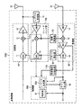
図3は、送受信機の別の実施形態を示す。図1で説明した要素と同一または同様の要素については、同一または同様の符号を付し、これ等については、詳細な説明を省略する。   FIG. 3 shows another embodiment of a transceiver. The same or similar elements as those described in FIG. 1 are denoted by the same or similar reference numerals, and detailed description thereof will be omitted.

図3に示した送受信機150Aは、送信部10、レプリカ生成部15a、受信部40、局部発振器50、クロック発生器60、フィードバック部70、制御部80aおよびキャンセル部90aを有する。   The transceiver 150A illustrated in FIG. 3 includes a transmission unit 10, a replica generation unit 15a, a reception unit 40, a local oscillator 50, a clock generator 60, a feedback unit 70, a control unit 80a, and a cancellation unit 90a.

レプリカ生成部15aは、図1に示したレプリカ生成部15と同様に、送信部10から受けた送信信号を送信信号のレプリカ信号とする。レプリカ生成部15aは、送信信号のレプリカ信号をフィードバック部70に出力する。また、レプリカ生成部15aは、制御部80aから指示を受けた時刻(すなわち、回り込み自干渉信号が到来する時刻)のタイミングで、送受信機150の記憶装置に保持された差分情報を用いて送信部10から受けた送信信号から回り込み自干渉信号のレプリカ信号を生成する。レプリカ生成部15aは、生成した回り込み自干渉信号のレプリカ信号をキャンセル部90aに出力する。   Similarly to the replica generation unit 15 illustrated in FIG. 1, the replica generation unit 15 a uses the transmission signal received from the transmission unit 10 as a replica signal of the transmission signal. The replica generation unit 15a outputs a replica signal of the transmission signal to the feedback unit 70. Further, the replica generation unit 15a uses the difference information held in the storage device of the transceiver 150 at the time when the instruction is received from the control unit 80a (that is, the time when the wraparound self-interference signal arrives). 10 generates a replica signal of the sneaking self-interference signal from the transmission signal received from 10. The replica generation unit 15a outputs the generated replica signal of the wraparound self-interference signal to the cancellation unit 90a.

制御部80aは、プロセッサ等であり、送受信機150Aに含まれるメモリ等の記憶装置に記憶されたプログラムを実行することで、送受信機150Aの各要素を制御する。また、制御部80aは、プログラムを実行することで、判定部81として動作する。   The control unit 80a is a processor or the like, and controls each element of the transceiver 150A by executing a program stored in a storage device such as a memory included in the transceiver 150A. Further, the control unit 80a operates as the determination unit 81 by executing a program.

例えば、制御部80aは、図1に示した制御部80と同様に、受信部40から受信した受信信号を用いて、受信アンテナ30を介して回り込み自干渉信号の到来した時刻を検出する。そして、制御部80aは、例えば、送信部10が送信信号を送信してから受信部40が回り込み自干渉信号を受信するまでの送信信号の伝播時間を求める。なお、回り込み自干渉信号の到来した時刻を検出する場合、制御部80aは、キャンセル部90aの動作を一時的に停止させる(すなわち、受信アンテナ30を介して受信した受信信号をそのまま通過させる)のが好ましい。そして、制御部80aは、回り込み自干渉信号の到来した時刻を検出した後、キャンセル部90aの動作を再開させる。   For example, similarly to the control unit 80 shown in FIG. 1, the control unit 80 a uses the received signal received from the receiving unit 40 to detect the time when the wraparound self-interference signal arrives via the receiving antenna 30. Then, for example, the control unit 80a obtains the transmission signal propagation time from when the transmission unit 10 transmits the transmission signal until the reception unit 40 receives the self-interference signal. When detecting the time when the wraparound self-interference signal arrives, the control unit 80a temporarily stops the operation of the cancel unit 90a (that is, passes the received signal received through the receiving antenna 30 as it is). Is preferred. And the control part 80a restarts the operation | movement of the cancellation part 90a, after detecting the time when the wraparound self-interference signal arrived.

また、送信アンテナ20と受信アンテナ30との配置に関連して送信アンテナ20と受信アンテナ30との間の距離や周辺環境(周辺の反射物として壁、天井、床、筐体の形状や材質など)のトレーニング開始時点で既知である情報から、回り込み自干渉信号の到来時刻や振幅および位相の変化量を予測し、それらの予測値に基づいて制御部80aがレプリカ生成部15aに指示し、トレーニング開始時点からキャンセル部90aを動作させてもよい。   Further, in relation to the arrangement of the transmission antenna 20 and the reception antenna 30, the distance between the transmission antenna 20 and the reception antenna 30 and the surrounding environment (such as the shape and material of walls, ceilings, floors, and casings as surrounding reflectors) ) From the information known at the time of the training start), the arrival time of the wraparound self-interference signal and the amount of change in the amplitude and phase are predicted, and the control unit 80a instructs the replica generation unit 15a based on the predicted values to perform training. The cancel unit 90a may be operated from the start time.

また、制御部80aは、図1に示した制御部80と同様に、フィードバック部70が生成したフィードバック信号と受信部40から受信した受信信号に含まれる回り込み自干渉信号とを比較する。制御部80aは、フィードバック信号と回り込み自干渉信号との間の相対的な振幅および位相の差を示す差分情報を求める。そして、制御部80aは、求めた差分情報と検出した時刻とを用いてレプリカ生成部15aを制御する。例えば、制御部80aは、伝播時間から求まる回り込み自干渉信号が到来する時刻のタイミングで、レプリカ生成部15aに対して、差分情報を用いて送信部10から受けた送信信号の振幅および位相を変化させ、送信信号のアナログのレプリカ信号を生成させる。そして、レプリカ生成部15aは、生成した送信信号のレプリカ信号をフィードバック部70に出力する。これにより、フィードバック部70は、受信部40から出力される受信信号と同じ時変動を示すフィードバック信号を生成できる。   Further, like the control unit 80 shown in FIG. 1, the control unit 80 a compares the feedback signal generated by the feedback unit 70 with the wraparound self-interference signal included in the reception signal received from the reception unit 40. The control unit 80a obtains difference information indicating a relative amplitude and phase difference between the feedback signal and the wraparound self-interference signal. Then, the control unit 80a controls the replica generation unit 15a using the obtained difference information and the detected time. For example, the control unit 80a changes the amplitude and phase of the transmission signal received from the transmission unit 10 using the difference information with respect to the replica generation unit 15a at the timing of the arrival of the wraparound self-interference signal obtained from the propagation time. And an analog replica signal of the transmission signal is generated. Then, the replica generation unit 15a outputs a replica signal of the generated transmission signal to the feedback unit 70. Thereby, the feedback unit 70 can generate a feedback signal that shows the same time variation as the reception signal output from the reception unit 40.

また、制御部80aは、伝播時間から求まる回り込み自干渉信号が到来する時刻のタイミング(すなわち、制御部80aから指示を受けたタイミング)で、レプリカ生成部15aに対し、差分情報を用いて送信部10からの送信信号の振幅および位相を変化させ、回り込み自干渉信号のアナログのレプリカ信号を生成させる。   In addition, the control unit 80a uses the difference information to transmit to the replica generation unit 15a at the time of arrival of the wraparound self-interference signal obtained from the propagation time (that is, the timing received from the control unit 80a). The amplitude and the phase of the transmission signal from 10 are changed, and an analog replica signal of the wraparound self-interference signal is generated.

キャンセル部90aは、レプリカ生成部15aにより生成された回り込み自干渉信号のレプリカ信号を用いて、受信信号に含まれる回り込み自干渉信号を除去する。例えば、キャンセル部90aは、回り込み自干渉信号のレプリカ信号を、受信アンテナ30を介して受信された受信信号に逆位相で合成し、受信信号に含まれる回り込み自干渉信号を除去する。そして、キャンセル部90aは、回り込み自干渉信号が除去された受信信号を、受信部40に出力する。   The cancel unit 90a removes the wraparound self-interference signal included in the received signal using the replica signal of the wraparound self-interference signal generated by the replica generation unit 15a. For example, the canceling unit 90a combines the replica signal of the wraparound self-interference signal with the reception signal received via the reception antenna 30 in the opposite phase, and removes the wraparound self-interference signal included in the reception signal. Then, the cancel unit 90a outputs the reception signal from which the wraparound self-interference signal is removed to the reception unit 40.

なお、受信信号が回り込み自干渉信号を含むことで、受信信号の電力が受信部40のLNA41やAGC43等における電力の許容レベルを超える場合がある。そこで、図3に示すように、送受信機150Aでは、キャンセル部90aを受信アンテナ30と受信部40との間に配置する。これにより、キャンセル部90aが、受信部40の前で回り込み自干渉信号を受信信号から除去することで、受信信号の電力を受信部40のLNA41等の許容レベル内に抑えることができる。   Note that, since the received signal includes a sneaking self-interference signal, the power of the received signal may exceed the allowable power level in the LNA 41, the AGC 43, or the like of the receiving unit 40. Therefore, as shown in FIG. 3, in the transceiver 150 </ b> A, the cancel unit 90 a is disposed between the reception antenna 30 and the reception unit 40. As a result, the cancel unit 90a removes the sneaking self-interference signal from the reception signal in front of the reception unit 40, so that the power of the reception signal can be suppressed within an allowable level such as the LNA 41 of the reception unit 40.

また、受信信号の電力が受信部40のLNA41の許容レベル内である場合は、受信部40のLNA41の出力後にキャンセル部90aを設置することも可能である。この場合、フィードバック部70のLNA41を省略し、フィードバック部70のLNA41による振幅および位相の変化量をレプリカ生成部15aにおける振幅および位相の変化量に合算し、受信部40のLNA41の出力後の回り込み自干渉信号のレプリカ信号として生成してもよい。   Further, when the power of the received signal is within the allowable level of the LNA 41 of the receiving unit 40, the cancel unit 90a can be installed after the output of the LNA 41 of the receiving unit 40. In this case, the LNA 41 of the feedback unit 70 is omitted, and the amplitude and phase changes due to the LNA 41 of the feedback unit 70 are added to the amplitude and phase changes in the replica generation unit 15a, and the wraparound after the output of the LNA 41 of the reception unit 40 is performed. You may generate | occur | produce as a replica signal of a self-interference signal.

図4は、図3に示した送受信機150Aにおける送受信処理の一例を示す。図4に示した処理は、例えば、送受信機150Aに含まれるプロセッサ等の制御部80aが記憶装置に記憶されるプログラムを実行することにより実現される。なお、図4に示した処理は、送受信機150Aに設けられるハードウェアにより実行されてもよい。この場合、図3に示した判定部81は、送受信機150A内に配置される回路により実現される。   FIG. 4 shows an example of transmission / reception processing in the transceiver 150A shown in FIG. The processing illustrated in FIG. 4 is realized, for example, when a control unit 80a such as a processor included in the transceiver 150A executes a program stored in the storage device. Note that the processing illustrated in FIG. 4 may be executed by hardware provided in the transceiver 150A. In this case, the determination unit 81 shown in FIG. 3 is realized by a circuit arranged in the transceiver 150A.

なお、図4に示したステップの動作のうち、図2に示したステップと同一または同様の処理を示すものについては、同一のステップ番号を付し、詳細な説明を省略する。   Note that among the operations of the steps shown in FIG. 4, those showing the same or similar processing as the steps shown in FIG. 2 are denoted by the same step numbers, and detailed description thereof is omitted.

送受信機150Aは、図4に示したステップS100からステップS140の処理を実行した後、ステップS145の処理を実行する。   The transceiver 150A executes the processing of step S145 after executing the processing of step S100 to step S140 shown in FIG.

ステップS145では、レプリカ生成部15aは、伝播時間から求まる回り込み自干渉信号が到来する時刻のタイミング(すなわち、制御部80aから指示を受けたタイミング)で、差分情報を用いて送信部10からの送信信号の振幅および位相を変化させ、回り込み自干渉信号のレプリカ信号を生成する。レプリカ生成部15aは、生成した回り込み自干渉信号のレプリカ信号をキャンセル部90aに出力する。   In step S145, the replica generation unit 15a performs transmission from the transmission unit 10 using the difference information at the timing of the arrival of the wraparound self-interference signal obtained from the propagation time (that is, the timing received from the control unit 80a). A replica signal of the self-interference signal is generated by changing the amplitude and phase of the signal. The replica generation unit 15a outputs the generated replica signal of the wraparound self-interference signal to the cancellation unit 90a.

ステップS155では、キャンセル部90aは、ステップS145で生成された回り込み自干渉信号のレプリカ信号を用いて、受信信号に含まれる回り込み自干渉信号を除去する。   In step S155, the cancel unit 90a removes the wraparound self-interference signal included in the received signal using the replica signal of the wraparound self-interference signal generated in step S145.

送受信機150Aは、ステップS155の処理を実行した後、ステップS160およびステップS170の処理を実行する。   The transmitter / receiver 150A executes the processing of step S155, and then executes the processing of step S160 and step S170.

以上、図3および図4に示した実施形態では、フィードバック部70は、受信部40が受信する受信信号に対して実行するのと同じ受信処理を、レプリカ生成部15aから受信した送信信号のレプリカ信号に対して実行し、フィードバック信号を生成する。制御部80aは、フィードバック信号と受信部40から受信した受信信号に含まれる回り込み自干渉信号とを比較し、フィードバック信号と回り込み自干渉信号との間の差分情報を求める。そして、レプリカ生成部15aは、制御部80aから受けた差分情報を用いて、送信部10から受けた送信信号の振幅および位相を変化させ、回り込み自干渉信号のレプリカ信号を生成する。   As described above, in the embodiment illustrated in FIGS. 3 and 4, the feedback unit 70 performs the same reception processing as the reception signal received by the reception unit 40 on the replica of the transmission signal received from the replica generation unit 15 a. Run on the signal to generate a feedback signal. The control unit 80a compares the feedback signal and the wraparound self-interference signal included in the reception signal received from the reception unit 40, and obtains difference information between the feedback signal and the wraparound self-interference signal. And the replica production | generation part 15a changes the amplitude and phase of the transmission signal received from the transmission part 10 using the difference information received from the control part 80a, and produces | generates the replica signal of a wraparound self-interference signal.

これにより、送受信機150Aは、回り込み自干渉信号が送受信機150A内でランダム性のある時変動を受ける場合でも、受信信号から回り込み自干渉信号を除去する信号を高い精度で生成できる。そして、送受信機150Aは、回り込み自干渉信号を除去する性能の向上を図ることができる。   Thereby, the transmitter / receiver 150A can generate a signal for removing the wraparound self-interference signal from the received signal with high accuracy even when the wraparound self-interference signal is subject to fluctuations in the transceiver 150A when there is randomness. The transceiver 150A can improve the performance of removing the self-interference signal.

また、キャンセル部90aが、受信アンテナ30と受信部40との間に配置され受信部40の前で回り込み自干渉信号を受信信号から除去することで、受信信号の電力を受信部40のLNA41等の電力の許容レベル内に抑えることができる。   In addition, the cancel unit 90a is disposed between the reception antenna 30 and the reception unit 40 and removes the sneaking self-interference signal from the reception signal in front of the reception unit 40, whereby the power of the reception signal is reduced to the LNA 41 of the reception unit 40, etc. Can be kept within an acceptable level of power.

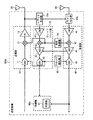
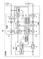
図5は、送受信機の別の実施形態を示す。図1で説明した要素と同一または同様の要素については、同一または同様の符号を付し、これ等については、詳細な説明を省略する。   FIG. 5 shows another embodiment of a transceiver. The same or similar elements as those described in FIG. 1 are denoted by the same or similar reference numerals, and detailed description thereof will be omitted.

図5に示した送受信機150Bは、送信部10、レプリカ生成部15、35(1)−35(N)、受信部40、局部発振器50、クロック発生器60、フィードバック部70、制御部80b、キャンセル部90bおよび残留成分除去部100を有する(Nは1以上の整数)。   The transceiver 150B illustrated in FIG. 5 includes a transmission unit 10, replica generation units 15, 35 (1) -35 (N), a reception unit 40, a local oscillator 50, a clock generator 60, a feedback unit 70, a control unit 80b, It has a canceling unit 90b and a residual component removing unit 100 (N is an integer of 1 or more).

レプリカ生成部35(35(1)−35(N))の各々は、伝播における遅延等により制御部80bが検出した回り込み自干渉信号の互いに異なるN個の到来した時刻の各々のタイミングで、差分情報を用いて送信部10から受けた送信信号から回り込み自干渉信号のレプリカ信号を生成する。各レプリカ生成部35は、生成した各回り込み自干渉信号のレプリカ信号をキャンセル部90bにそれぞれ出力する。   Each of the replica generation units 35 (35 (1) -35 (N)) has a difference at each of N different arrival times of the wraparound self-interference signal detected by the control unit 80b due to a delay in propagation or the like. Using the information, a replica signal of the self-interference signal is generated from the transmission signal received from the transmission unit 10. Each replica generation unit 35 outputs the generated replica signal of each wraparound self-interference signal to the cancellation unit 90b.

制御部80bは、プロセッサ等であり、送受信機150Bに含まれるメモリ等の記憶装置に記憶されたプログラムを実行することで、送受信機150Bの各要素を制御する。また、制御部80bは、プログラムを実行することで、判定部81として動作する。   The control unit 80b is a processor or the like, and controls each element of the transceiver 150B by executing a program stored in a storage device such as a memory included in the transceiver 150B. In addition, the control unit 80b operates as the determination unit 81 by executing a program.

例えば、制御部80bは、図1に示した制御部80と同様に、受信部40から受信した受信信号を用いて、受信アンテナ30を介して回り込み自干渉信号の到来した時刻を検出する。なお、回り込み自干渉信号は、伝播において遅延等の影響を受けた場合、互いに異なる複数の時刻に受信アンテナ30を介して受信される。この場合、制御部80bは、例えば、N個の到来した時刻を検出する。そして、制御部80bは、送信部10が送信信号を送信してから受信部40が回り込み自干渉信号を受信するまでの伝播時間をそれぞれ求める。   For example, similarly to the control unit 80 shown in FIG. 1, the control unit 80 b uses the received signal received from the receiving unit 40 to detect the time when the wraparound self-interference signal arrives via the receiving antenna 30. Note that the wraparound self-interference signal is received via the receiving antenna 30 at a plurality of different times when affected by a delay or the like in propagation. In this case, the control unit 80b detects, for example, N arrival times. And the control part 80b calculates | requires the propagation time after the transmission part 10 transmits a transmission signal until the receiving part 40 wraps around and receives an own interference signal, respectively.

なお、回り込み自干渉信号の到来した時刻を検出する場合、制御部80bは、キャンセル部90bの動作を一時的に停止させる(すなわち、受信アンテナ30を介して受信した受信信号をそのまま通過させる)のが好ましい。そして、制御部80bは、回り込み自干渉信号の到来した時刻を検出した後、キャンセル部90bの動作を再開させる。   When detecting the time when the wraparound self-interference signal arrives, the control unit 80b temporarily stops the operation of the cancel unit 90b (that is, passes the received signal received through the receiving antenna 30 as it is). Is preferred. And the control part 80b restarts the operation | movement of the cancellation part 90b, after detecting the time when the wraparound self-interference signal arrived.

また、送信アンテナ20と受信アンテナ30との配置に関連して送信アンテナ20と受信アンテナ30との間の距離や周辺環境(周辺の反射物として壁、天井、床、筐体の形状や材質など)のトレーニング開始時点で既知である情報から、回り込み自干渉信号の到来時刻や振幅および位相の変化量を予測し、それらの予測値に基づいて制御部80bがレプリカ生成部35(1)−35(N)に指示し、トレーニング開始時点からキャンセル部90bを動作させてもよい。   Further, in relation to the arrangement of the transmission antenna 20 and the reception antenna 30, the distance between the transmission antenna 20 and the reception antenna 30 and the surrounding environment (such as the shape and material of walls, ceilings, floors, and casings as surrounding reflectors) ), The arrival time of the sneak self-interference signal and the amount of change in the amplitude and phase are predicted from the information known at the start of training, and the control unit 80b uses the predicted values to generate the replica generation unit 35 (1) -35. (N) may be instructed, and the cancel unit 90b may be operated from the training start time.

また、遅延等の影響を受けて到来時刻が複数検出されるとき、検出する到来時刻の数はN個より少なくてもよく、多い場合はN個で打ち切るようにしてもよい。そして、レプリカ生成部35(1)−35(N)もその検出した到来時刻の数に合わせて動作させればよい。さらに、1回目のトレーニングで全N個の回り込み自干渉信号のレプリカ信号を生成する必要はなく、複数回のトレーニングやトレーニング後の運用時に更新してもよい。すなわち、一度のトレーニングで検出して生成した回り込み自干渉信号のレプリカ信号を用いてキャンセルした後の受信信号から、さらに検出された回り込み自干渉信号の到来波を追加してレプリカ信号を生成してもよい。   Further, when a plurality of arrival times are detected due to the influence of delay or the like, the number of arrival times to be detected may be less than N, and may be terminated when there are more. And the replica production | generation part 35 (1) -35 (N) should just operate | move according to the number of the detected arrival times. Further, it is not necessary to generate replica signals of all N wraparound self-interference signals in the first training, and it may be updated at the time of a plurality of trainings and operations after training. That is, a replica signal is generated by adding an incoming wave of the detected wraparound self-interference signal from the received signal after cancellation using a replica signal of the wraparound self-interference signal detected and generated by one training. Also good.

そして、制御部80bは、図1に示した制御部80と同様に、フィードバック部70が生成したフィードバック信号と受信部40から受信した受信信号に含まれる回り込み自干渉信号とを比較する。なお、フィードバック信号と比較する回り込み自干渉信号は、例えば、到来した時刻が最も早い(すなわち、遅延を受けずに受信された)回り込み自干渉信号とする。制御部80bは、フィードバック信号と回り込み自干渉信号との間の相対的な振幅および位相の差を示す差分情報を求める。そして、制御部80bは、求めた差分情報と検出した時刻とを用いてレプリカ生成部15を制御する。これにより、フィードバック部70は、受信部40から出力される受信信号と同じ時変動を示すフィードバック信号を生成できる。   And the control part 80b compares the feedback signal which the feedback part 70 produced | generated with the self-interference signal contained in the received signal received from the receiving part 40 similarly to the control part 80 shown in FIG. Note that the wraparound self-interference signal to be compared with the feedback signal is, for example, a wraparound self-interference signal having the earliest arrival time (that is, received without delay). The control unit 80b obtains difference information indicating a relative amplitude and phase difference between the feedback signal and the wraparound self-interference signal. Then, the control unit 80b controls the replica generation unit 15 using the obtained difference information and the detected time. Thereby, the feedback unit 70 can generate a feedback signal that shows the same time variation as the reception signal output from the reception unit 40.

また、制御部80bは、求めた差分情報と検出したN個の時刻とを用いて各レプリカ生成部35を制御する。例えば、制御部80bは、各伝播時間から求まる回り込み自干渉信号が到来する時刻の各々のタイミングで、各レプリカ生成部35に対して、差分情報を用いて送信部10からの送信信号の振幅および位相を変化させ、回り込み自干渉信号のアナログのレプリカ信号を生成させる。   Further, the control unit 80b controls each replica generation unit 35 using the obtained difference information and the detected N times. For example, the control unit 80b transmits the amplitude of the transmission signal from the transmission unit 10 to each replica generation unit 35 using the difference information at each timing when the wraparound self-interference signal obtained from each propagation time arrives. The phase is changed to generate an analog replica signal of the wraparound self-interference signal.

キャンセル部90bは、各レプリカ生成部35により生成された各回り込み自干渉信号のレプリカ信号を用いて、受信信号に含まれる回り込み自干渉信号を除去する。例えば、キャンセル部90bは、各レプリカ生成部35からの回り込み自干渉信号のレプリカ信号を、受信アンテナ30を介して受信された受信信号に逆位相で合成し、受信信号に含まれる回り込み自干渉信号を除去する。そして、キャンセル部90bは、回り込み自干渉信号が除去された受信信号を、受信部40に出力する。   The cancel unit 90b removes the wraparound self-interference signal included in the received signal using the replica signal of each wraparound self-interference signal generated by each replica generation unit 35. For example, the cancel unit 90b synthesizes the replica signal of the wraparound self-interference signal from each replica generation unit 35 with the reception signal received via the reception antenna 30 in the opposite phase, and the wraparound self-interference signal included in the reception signal. Remove. Then, the cancel unit 90b outputs the reception signal from which the wraparound self-interference signal is removed to the reception unit 40.

なお、受信信号が回り込み自干渉信号を含むことで、受信信号の電力が受信部40のLNA41やAGC43等における電力の許容レベルを超える場合がある。そこで、図5に示すように、送受信機150Bでは、キャンセル部90bを受信アンテナ30と受信部40との間に配置する。これにより、キャンセル部90bが、受信部40の前で回り込み自干渉信号を受信信号から除去することで、受信信号の電力を受信部40のLNA41等の許容レベル内に抑えることができる。   Note that, since the received signal includes a sneaking self-interference signal, the power of the received signal may exceed the allowable power level in the LNA 41, the AGC 43, or the like of the receiving unit 40. Therefore, as shown in FIG. 5, in the transceiver 150 </ b> B, the cancel unit 90 b is disposed between the reception antenna 30 and the reception unit 40. As a result, the cancel unit 90b removes the sneaking self-interference signal from the reception signal in front of the reception unit 40, so that the power of the reception signal can be suppressed within an allowable level such as the LNA 41 of the reception unit 40.

残留成分除去部100は、フィードバック部70から受信した回り込み自干渉信号の残留成分のレプリカ信号を用いて、受信部40から受信した受信信号に残留する回り込み自干渉信号の残留成分を除去する。すなわち、受信信号に含まれる回り込み自干渉信号は、伝播において歪みや遅延等を受けるため、キャンセル部90bにより除去されず残留成分として残る。そこで、制御部80bは、例えば、差分情報における回り込み自干渉信号の到来する時刻、振幅および位相を調整し、レプリカ生成部15に調整した送信信号のレプリカ信号を生成させる。フィードバック部70は、回り込み自干渉信号の残留成分が到来する時刻のタイミングで、レプリカ生成部15により調整された送信信号のレプリカ信号に対して受信処理を実行し、回り込み自干渉信号の残留成分を示すフィードバック信号を生成する。フィードバック部70は、生成したフィードバック信号を回り込み自干渉信号の残留成分のレプリカ信号として残留成分除去部100に出力する。   The residual component removing unit 100 removes the residual component of the wraparound self-interference signal remaining in the reception signal received from the reception unit 40 using the replica signal of the residual component of the wraparound self-interference signal received from the feedback unit 70. That is, the wraparound self-interference signal included in the received signal is subjected to distortion, delay, and the like in propagation, and therefore remains as a residual component without being removed by the cancel unit 90b. Therefore, for example, the control unit 80b adjusts the arrival time, amplitude, and phase of the wraparound self-interference signal in the difference information, and causes the replica generation unit 15 to generate a replica signal of the adjusted transmission signal. The feedback unit 70 performs reception processing on the replica signal of the transmission signal adjusted by the replica generation unit 15 at the time when the residual component of the wraparound self-interference signal arrives, and determines the residual component of the wraparound self-interference signal. A feedback signal is generated. The feedback unit 70 wraps around the generated feedback signal and outputs it to the residual component removal unit 100 as a replica signal of the residual component of the self-interference signal.

残留成分除去部100は、フィードバック部70から受信した回り込み自干渉信号の残留成分のレプリカ信号を用いて、受信部40から受信した受信信号に残留する回り込み自干渉信号の残留成分を除去する。例えば、残留成分除去部100は、回り込み自干渉信号の残留成分のレプリカ信号を、受信部40から受信した受信信号に逆位相で合成し、受信信号に含まれる回り込み自干渉信号の残留成分を除去する。   The residual component removing unit 100 removes the residual component of the wraparound self-interference signal remaining in the reception signal received from the reception unit 40 using the replica signal of the residual component of the wraparound self-interference signal received from the feedback unit 70. For example, the residual component removal unit 100 synthesizes a replica signal of the residual component of the wraparound self-interference signal with the reception signal received from the reception unit 40 in reverse phase, and removes the residual component of the wraparound self-interference signal included in the reception signal. To do.

図6は、図5に示した送受信機150Bにおける送受信処理の一例を示す。図6に示した処理は、例えば、送受信機150Bに含まれるプロセッサ等の制御部80bが記憶装置に記憶されるプログラムを実行することにより実現される。なお、図6に示した処理は、送受信機150Bに設けられるハードウェアにより実行されてもよい。この場合、図5に示した判定部81は、送受信機150B内に配置される回路により実現される。   FIG. 6 shows an example of transmission / reception processing in the transceiver 150B shown in FIG. The processing illustrated in FIG. 6 is realized, for example, when a control unit 80b such as a processor included in the transceiver 150B executes a program stored in the storage device. Note that the processing illustrated in FIG. 6 may be executed by hardware provided in the transceiver 150B. In this case, the determination unit 81 shown in FIG. 5 is realized by a circuit arranged in the transceiver 150B.

なお、図6に示したステップの動作のうち、図2に示したステップと同一または同様の処理を示すものについては、同一のステップ番号を付し、詳細な説明を省略する。   Note that among the operations of the steps shown in FIG. 6, those showing the same or similar processing as the steps shown in FIG. 2 are denoted by the same step numbers, and detailed description thereof is omitted.

送受信機150Bは、図6に示したステップS100からステップS140の処理を実行した後、ステップS145aの処理を実行する。   The transceiver 150B executes the processing of step S145a after executing the processing of step S100 to step S140 shown in FIG.

ステップS145aでは、各レプリカ生成部35は、各伝播時間から求まる回り込み自干渉信号が到来する時刻のタイミング(すなわち、制御部80aから互いに異なる時刻に指示を受けたタイミング)で、差分情報を用いて送信部10からの送信信号の振幅および位相を変化させ、回り込み自干渉信号のレプリカ信号を生成する。各レプリカ生成部35は、生成した各回り込み自干渉信号のレプリカ信号をキャンセル部90bにそれぞれ出力する。   In step S145a, each replica generation unit 35 uses the difference information at the timing of the arrival of the wraparound self-interference signal obtained from each propagation time (that is, the timing received from the control unit 80a at a different time). The amplitude and phase of the transmission signal from the transmission unit 10 are changed to generate a replica signal of the wraparound self-interference signal. Each replica generation unit 35 outputs the generated replica signal of each wraparound self-interference signal to the cancellation unit 90b.

ステップS155aでは、キャンセル部90bは、ステップS145aで各レプリカ生成部35により生成された回り込み自干渉信号のレプリカ信号を用いて、受信信号に含まれる回り込み自干渉信号を除去する。   In step S155a, the cancel unit 90b removes the wraparound self-interference signal included in the received signal using the replica signal of the wraparound self-interference signal generated by each replica generation unit 35 in step S145a.

ステップS156では、制御部80bは、差分情報における回り込み自干渉信号の到来する時刻、振幅および位相を調整し、調整した差分情報を用いてレプリカ生成部15およびフィードバック部70に回り込み自干渉信号の残留成分のレプリカ信号を生成させる。すなわち、レプリカ生成部15は、調整された差分情報を用いて振幅および位相を調整した送信信号のレプリカ信号を生成する。フィードバック部70は、回り込み自干渉信号の残留成分が到来する時刻のタイミングで、レプリカ生成部15により調整された送信信号のレプリカ信号に対して受信処理を実行し、回り込み自干渉信号の残留成分を示すフィードバック信号を生成する。そして、フィードバック部70は、生成したフィードバック信号を回り込み自干渉信号の残留成分のレプリカ信号として残留成分除去部100に出力する。   In step S156, the control unit 80b adjusts the arrival time, amplitude, and phase of the wraparound self-interference signal in the difference information, and uses the adjusted difference information to return to the replica generation unit 15 and the feedback unit 70, where the wraparound self-interference signal remains. A component replica signal is generated. That is, the replica generation unit 15 generates a replica signal of the transmission signal whose amplitude and phase are adjusted using the adjusted difference information. The feedback unit 70 performs reception processing on the replica signal of the transmission signal adjusted by the replica generation unit 15 at the time when the residual component of the wraparound self-interference signal arrives, and determines the residual component of the wraparound self-interference signal. A feedback signal is generated. Then, the feedback unit 70 wraps around the generated feedback signal and outputs it to the residual component removal unit 100 as a replica signal of the residual component of the self-interference signal.

ステップS157では、残留成分除去部100は、ステップS156で生成された回り込み自干渉信号の残留成分のレプリカ信号を用いて、受信部40から受信した受信信号に含まれる回り込み自干渉信号の残留成分を除去する。   In step S157, the residual component removal unit 100 uses the replica signal of the residual component of the wraparound self-interference signal generated in step S156 to obtain the residual component of the wraparound self-interference signal included in the received signal received from the reception unit 40. Remove.

送受信機150Bは、ステップS157の処理を実行した後、ステップS160およびステップS170の処理を実行する。   The transceiver 150B executes the processing of step S157, and then executes the processing of step S160 and step S170.

以上、図5および図6に示した実施形態では、フィードバック部70は、受信部40が受信する受信信号に対して実行するのと同じ受信処理をレプリカ生成部15から受信した送信信号のレプリカ信号に対して実行し、フィードバック信号を生成する。制御部80bは、フィードバック信号と受信部40から受信した受信信号に含まれる回り込み自干渉信号との比較から、遅延等により回り込み自干渉信号の到来した時刻を複数検出するとともに、フィードバック信号と回り込み自干渉信号との間の差分情報を求める。そして、制御部80bは、検出した各時刻のタイミングで、レプリカ生成部35のそれぞれに、求めた差分情報を用いて送信部10から受けた送信信号の振幅および位相を変化させ、回り込み自干渉信号のレプリカ信号を生成させる。   As described above, in the embodiment illustrated in FIGS. 5 and 6, the feedback unit 70 performs the same reception processing as the reception signal received by the reception unit 40 from the replica generation unit 15. To generate a feedback signal. The control unit 80b detects a plurality of times when the wraparound self-interference signal arrives due to a delay or the like from the comparison between the feedback signal and the wraparound self-interference signal included in the received signal received from the reception unit 40, and also detects the feedback signal and The difference information between the interference signals is obtained. Then, the control unit 80b changes the amplitude and phase of the transmission signal received from the transmission unit 10 to each of the replica generation units 35 using the obtained difference information at the timing of each detected time, and the wraparound self-interference signal The replica signal is generated.

これにより、送受信機150Bは、回り込み自干渉信号が送受信機150B内でランダム性のある時変動を受ける場合でも、受信信号から回り込み自干渉信号を除去する信号を高い精度で生成できる。そして、送受信機150Bは、回り込み自干渉信号を除去する性能の向上を図ることができる。   Thus, the transceiver 150B can generate a signal for removing the wraparound self-interference signal from the received signal with high accuracy even when the wraparound self-interference signal is subject to fluctuations when there is randomness in the transceiver 150B. The transceiver 150B can improve the performance of removing the self-interference signal.

また、制御部80bは、差分情報における回り込み自干渉信号の到来する時刻、振幅および位相を調整し、調整した差分情報を用いてレプリカ生成部15およびフィードバック部70に回り込み自干渉信号の残留成分のレプリカ信号を生成させる。そして、残留成分除去部100は、生成された回り込み自干渉信号の残留成分のレプリカ信号を用いて、受信部40から受信した受信信号に含まれる回り込み自干渉信号の残留成分を除去する。これにより、送受信機150Bは、受信する回り込み自干渉信号を受信信号から高い精度で除去できる。   Further, the control unit 80b adjusts the arrival time, amplitude, and phase of the wraparound self-interference signal in the difference information, and uses the adjusted difference information to the replica generation unit 15 and the feedback unit 70 to determine the residual component of the wraparound self-interference signal. A replica signal is generated. Then, the residual component removal unit 100 removes the residual component of the wraparound self-interference signal included in the received signal received from the reception unit 40, using the generated replica signal of the residual component of the wraparound self-interference signal. Thereby, the transceiver 150B can remove the received wraparound self-interference signal from the received signal with high accuracy.

また、キャンセル部90bが、受信アンテナ30と受信部40との間に配置され、受信部40の前で回り込み自干渉信号を受信信号から除去することで、受信信号の電力を受信部40のLNA41等の電力の許容レベル内に抑えることができる。   In addition, the cancel unit 90b is disposed between the reception antenna 30 and the reception unit 40, and removes the sneaking self-interference signal from the reception signal in front of the reception unit 40, whereby the power of the reception signal is reduced to the LNA 41 of the reception unit 40. The power level can be kept within the allowable level.

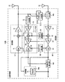
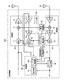
図7は、送受信機の別の実施形態を示す。図1で説明した要素と同一または同様の要素については、同一または同様の符号を付し、これ等については、詳細な説明を省略する。   FIG. 7 shows another embodiment of a transceiver. The same or similar elements as those described in FIG. 1 are denoted by the same or similar reference numerals, and detailed description thereof will be omitted.

図7に示した送受信機150Cは、送信部10、受信部40、局部発振器50、クロック発生器60、フィードバック部70、制御部80c、キャンセル部90および時変動成分抽出部110を有する。   The transceiver 150C illustrated in FIG. 7 includes a transmission unit 10, a reception unit 40, a local oscillator 50, a clock generator 60, a feedback unit 70, a control unit 80c, a cancellation unit 90, and a time variation component extraction unit 110.

制御部80cは、プロセッサ等であり、送受信機150Cに含まれるメモリ等の記憶装置に記憶されたプログラムを実行することで、送受信機150Cの各要素を制御する。また、制御部80cは、プログラムを実行することで、判定部81およびレプリカ生成部82として動作する。   The control unit 80c is a processor or the like, and controls each element of the transceiver 150C by executing a program stored in a storage device such as a memory included in the transceiver 150C. Further, the control unit 80c operates as the determination unit 81 and the replica generation unit 82 by executing the program.

レプリカ生成部82は、データを含むデジタルの送信信号を受信する。また、レプリカ生成部82は、後述する時変動成分抽出部110が抽出した送信信号の振幅および位相の時変動成分(すなわち、局部発振器50のLO信号およびクロック発生器60のクロック信号等)を取得する。レプリカ生成部82は、取得した時変動成分を用いて受信したデジタルの送信信号の振幅および位相を変化させて、送信部10のDAC11およびミキサ12の処理を擬似的に受けた送信信号のレプリカ信号を生成する。レプリカ生成部82は、制御部80cに含まれるDAC等を介して、生成した送信信号のレプリカ信号をフィードバック部70に出力する。これにより、フィードバック部70は、フィードバック信号を生成できる。   The replica generation unit 82 receives a digital transmission signal including data. In addition, the replica generation unit 82 acquires the time variation component of the amplitude and phase of the transmission signal extracted by the time variation component extraction unit 110 described later (that is, the LO signal of the local oscillator 50, the clock signal of the clock generator 60, and the like). To do. The replica generation unit 82 changes the amplitude and phase of the digital transmission signal received using the acquired time-varying component, and the replica signal of the transmission signal subjected to pseudo processing of the DAC 11 and the mixer 12 of the transmission unit 10 Is generated. The replica generation unit 82 outputs a replica signal of the generated transmission signal to the feedback unit 70 via a DAC or the like included in the control unit 80c. Thereby, the feedback unit 70 can generate a feedback signal.

また、制御部80cは、図1に示した制御部80と同様に、受信部40から受信した受信信号を用いて、受信アンテナ30を介して回り込み自干渉信号の到来した時刻を検出する。そして、制御部80cは、例えば、送信部10が送信信号を送信してから受信部40が回り込み自干渉信号を受信するまでの送信信号の伝播時間を求める。   Similarly to the control unit 80 shown in FIG. 1, the control unit 80 c uses the received signal received from the receiving unit 40 to detect the time when the wraparound self-interference signal arrives via the receiving antenna 30. Then, for example, the control unit 80c obtains the propagation time of the transmission signal from when the transmission unit 10 transmits the transmission signal until the reception unit 40 receives the self-interference signal.

また、制御部80cは、図1に示した制御部80と同様に、フィードバック部70が生成したフィードバック信号と受信部40から受信した受信信号に含まれる回り込み自干渉信号とを比較する。制御部80cは、フィードバック信号と回り込み自干渉信号との間の相対的な振幅および位相の差を示す差分情報を求める。そして、制御部80cは、求めた差分情報と検出した時刻とを用いてレプリカ生成部82を制御する。例えば、制御部80aは、伝播時間から求まる回り込み自干渉信号が到来する時刻のタイミングで、レプリカ生成部82に対して、差分情報を用いて送信信号の振幅および位相を変化させ、送信信号のレプリカ信号を生成させる。そして、レプリカ生成部82は、生成した送信信号のレプリカ信号をフィードバック部70に出力する。これにより、フィードバック部70は、受信部40から出力される受信信号と同じ時変動を示すフィードバック信号を生成できる。   Further, like the control unit 80 shown in FIG. 1, the control unit 80 c compares the feedback signal generated by the feedback unit 70 with the wraparound self-interference signal included in the reception signal received from the reception unit 40. The control unit 80c obtains difference information indicating a relative amplitude and phase difference between the feedback signal and the wraparound self-interference signal. Then, the control unit 80c controls the replica generation unit 82 using the obtained difference information and the detected time. For example, the control unit 80a causes the replica generation unit 82 to change the amplitude and phase of the transmission signal using the difference information at the timing of the arrival of the wraparound self-interference signal obtained from the propagation time. Generate a signal. Then, the replica generation unit 82 outputs the replica signal of the generated transmission signal to the feedback unit 70. Thereby, the feedback unit 70 can generate a feedback signal that shows the same time variation as the reception signal output from the reception unit 40.

時変動成分抽出部110は、送受信機150Cが送信する送信信号における振幅および位相等の時変動成分を抽出する。例えば、時変動成分抽出部110は、送信信号における振幅および位相等の時変動成分として、局部発振器50のLO信号およびクロック発生器60のクロック信号をそれぞれ受信する。そして、時変動成分抽出部110は、局部発振器50およびクロック発生器60の各々から受信した信号を、時変動成分抽出部110に含まれるADCを用いてサンプリングし、サンプリングした各信号を制御部80cに出力する。なお、時変動成分抽出部110は、局部発振器50のLO信号あるいはLO信号の位相雑音をサンプリングし、送信信号における振幅あるいは位相の時変動成分として抽出する。また、時変動成分抽出部110は、クロック発生器60のクロック信号あるいはクロックジッタをサンプリングし、送信信号における振幅および位相の時変動成分として抽出する。   The time variation component extraction unit 110 extracts time variation components such as amplitude and phase in the transmission signal transmitted by the transceiver 150C. For example, the time variation component extraction unit 110 receives the LO signal of the local oscillator 50 and the clock signal of the clock generator 60 as time variation components such as amplitude and phase in the transmission signal. Then, the time variation component extraction unit 110 samples the signals received from each of the local oscillator 50 and the clock generator 60 by using the ADC included in the time variation component extraction unit 110, and each sampled signal is controlled by the control unit 80c. Output to. The time variation component extraction unit 110 samples the LO signal of the local oscillator 50 or the phase noise of the LO signal, and extracts it as a time variation component of the amplitude or phase in the transmission signal. The time variation component extraction unit 110 samples the clock signal or clock jitter of the clock generator 60 and extracts it as a time variation component of the amplitude and phase in the transmission signal.

図8は、図7に示した送受信機150Cにおける送受信処理の一例を示す。図8に示した処理は、例えば、送受信機150Cに含まれるプロセッサ等の制御部80cが記憶装置に記憶されるプログラムを実行することにより実現される。なお、図8に示した処理は、送受信機150Cに設けられるハードウェアにより実行されてもよい。この場合、図7に示した判定部81およびレプリカ生成部82は、送受信機150C内に配置される回路により実現される。   FIG. 8 shows an example of transmission / reception processing in the transceiver 150C shown in FIG. The processing illustrated in FIG. 8 is realized, for example, when a control unit 80c such as a processor included in the transceiver 150C executes a program stored in the storage device. Note that the processing illustrated in FIG. 8 may be executed by hardware provided in the transceiver 150C. In this case, the determination unit 81 and the replica generation unit 82 illustrated in FIG. 7 are realized by a circuit arranged in the transceiver 150C.

なお、図8に示したステップの動作のうち、図2に示したステップと同一または同様の処理を示すものについては、同一のステップ番号を付し、詳細な説明を省略する。   Note that among the operations of the steps shown in FIG. 8, those showing the same or similar processing as the steps shown in FIG. 2 are denoted by the same step numbers, and detailed description thereof is omitted.

送受信機150Cは、図8に示したステップS100の処理を実行した後、ステップS105の処理を実行する。   The transceiver 150C executes the process of step S105 shown in FIG. 8, and then executes the process of step S105.

ステップS105では、時変動成分抽出部110は、送受信機150Cが送信する送信信号(すなわちトレーニング信号)における振幅および位相等の時変動成分を抽出する。例えば、時変動成分抽出部110は、送信信号における振幅および位相の時変動成分として、局部発振器50のLO信号およびクロック発生器60のクロック信号をそれぞれ受信する。そして、時変動成分抽出部110は、局部発振器50およびクロック発生器60の各々から受信した信号を、時変動成分抽出部110に含まれるADCを用いてサンプリングし制御部80cに出力する。   In step S105, the time variation component extraction unit 110 extracts time variation components such as amplitude and phase in the transmission signal (that is, the training signal) transmitted by the transceiver 150C. For example, the time variation component extraction unit 110 receives the LO signal of the local oscillator 50 and the clock signal of the clock generator 60 as time variation components of the amplitude and phase in the transmission signal. Then, the time variation component extraction unit 110 samples the signal received from each of the local oscillator 50 and the clock generator 60 using the ADC included in the time variation component extraction unit 110, and outputs the sampled signal to the control unit 80c.

ステップS115では、レプリカ生成部82は、デジタルの送信信号(トレーニング信号)と、ステップS105で抽出された送信信号の振幅および位相の時変動成分(すなわち、局部発振器50のLO信号およびクロック発生器60のクロックジッタ)とを用いて、送信部10が送信する送信信号のレプリカ信号を生成する。さらに、送信信号がミキサ12あるいはPA13による非線形特性の影響を受ける場合は、デジタル信号処理等により送信信号のレプリカ信号に上記非線形特性を付加してもよい。また、送信部10に入力するトレーニング信号にプリディストーション処理等を施し、非線形特性の影響をキャンセルするようにしてもよい。   In step S115, the replica generation unit 82 performs time variation components of the digital transmission signal (training signal) and the amplitude and phase of the transmission signal extracted in step S105 (that is, the LO signal and clock generator 60 of the local oscillator 50). And a replica signal of the transmission signal transmitted by the transmission unit 10 is generated. Further, when the transmission signal is affected by the nonlinear characteristic of the mixer 12 or PA 13, the nonlinear characteristic may be added to the replica signal of the transmission signal by digital signal processing or the like. Moreover, the predistortion process etc. may be performed to the training signal input into the transmission part 10, and the influence of a nonlinear characteristic may be canceled.

送受信機150Cは、ステップS115の処理を実行した後、ステップS120からステップS170の処理を実行する。   The transceiver 150C executes the process of step S115, and then executes the process of step S120 to step S170.

以上、図7および図8に示した実施形態では、レプリカ生成部82は、時変動成分抽出部110により抽出された送信信号における振幅および位相の時変動成分を用いて、デジタルの送信信号のレプリカ信号を生成する。フィードバック部70は、受信部40が受信する受信信号に対して実行するのと同じ受信処理を、レプリカ生成部82により生成された送信信号のレプリカ信号に対して実行し、フィードバック信号(すなわち、回り込み自干渉信号のレプリカ信号)を生成する。これにより、送受信機150Cは、回り込み自干渉信号が送受信機150C内でランダム性のある時変動を受ける場合でも、受信信号から回り込み自干渉信号を除去する信号を高い精度で生成できる。そして、送受信機150Cは、回り込み自干渉信号を除去する性能の向上を図ることができる。   As described above, in the embodiment shown in FIGS. 7 and 8, the replica generation unit 82 uses the time-varying component of the amplitude and phase in the transmission signal extracted by the time-varying component extraction unit 110 to replicate the digital transmission signal. Generate a signal. The feedback unit 70 performs the same reception process as that performed on the reception signal received by the reception unit 40 on the replica signal of the transmission signal generated by the replica generation unit 82, and outputs a feedback signal (that is, a wraparound). A replica signal of the self-interference signal). Thus, the transceiver 150C can generate a signal for removing the wraparound self-interference signal from the received signal with high accuracy even when the wraparound self-interference signal is subject to fluctuations when there is randomness in the transceiver 150C. The transceiver 150C can improve the performance of removing the self-interference signal.

図9は、送受信機の別の実施形態を示す。図1で説明した要素と同一または同様の要素については、同一または同様の符号を付し、これ等については、詳細な説明を省略する。   FIG. 9 shows another embodiment of a transceiver. The same or similar elements as those described in FIG. 1 are denoted by the same or similar reference numerals, and detailed description thereof will be omitted.

図9に示した送受信機150Dは、送信部10、レプリカ生成部15、受信部40、局部発振器50、クロック発生器60、フィードバック部70a、制御部80d、キャンセル部90および時変動成分抽出部110aを有する。   The transceiver 150D illustrated in FIG. 9 includes a transmission unit 10, a replica generation unit 15, a reception unit 40, a local oscillator 50, a clock generator 60, a feedback unit 70a, a control unit 80d, a cancellation unit 90, and a time variation component extraction unit 110a. Have

フィードバック部70aは、LNA41、AGC43およびADC44を有する。すなわち、フィードバック部70aは、例えば、図1に示したフィードバック部70のミキサ42が省略される。そして、フィードバック部70aは、ミキサ42による処理が除外された受信処理を、レプリカ生成部15から受信した送信信号のレプリカ信号に対して実行し、フィードバック信号を生成する。フィードバック部70aは、生成したフィードバック信号を制御部80dに出力する。なお、フィードバック部70aは、ミキサ42の代わりに、AGC43やADC44が省略されてもよい。   The feedback unit 70a includes an LNA 41, an AGC 43, and an ADC 44. That is, in the feedback unit 70a, for example, the mixer 42 of the feedback unit 70 illustrated in FIG. 1 is omitted. Then, the feedback unit 70a performs the reception process from which the process by the mixer 42 is excluded, on the replica signal of the transmission signal received from the replica generation unit 15, and generates a feedback signal. The feedback unit 70a outputs the generated feedback signal to the control unit 80d. The feedback unit 70 a may omit the AGC 43 and the ADC 44 instead of the mixer 42.

時変動成分抽出部110aは、送受信機150Dが受信する受信信号の時変動成分のうち、フィードバック部70aで除外されたミキサ42による処理に対応する時変動成分を抽出する。例えば、時変動成分抽出部110aは、ミキサ42による処理に対応する時変動成分として、局部発振器50のLO信号を受信する。すなわち、時変動成分抽出部110aは、局部発振器50から受信したLO信号を、時変動成分抽出部110aに含まれるADCを用いてサンプリングし、サンプリングした信号を制御部80dに出力する。すなわち、時変動成分抽出部110aは、局部発振器50のLO信号あるいはLO信号の位相雑音を、ミキサ42による処理に対応する時変動成分として抽出する。なお、時変動成分抽出部110は、フィードバック部70aにおいてAGC43やADC44が省略される場合、AGC43からの信号あるいはクロック発生器60からの信号を時変動成分として抽出してもよい。   The time variation component extraction unit 110a extracts time variation components corresponding to the processing by the mixer 42 excluded by the feedback unit 70a from the time variation components of the received signal received by the transceiver 150D. For example, the time variation component extraction unit 110 a receives the LO signal of the local oscillator 50 as the time variation component corresponding to the processing by the mixer 42. That is, the time variation component extraction unit 110a samples the LO signal received from the local oscillator 50 using the ADC included in the time variation component extraction unit 110a, and outputs the sampled signal to the control unit 80d. That is, the time variation component extraction unit 110 a extracts the LO signal of the local oscillator 50 or the phase noise of the LO signal as a time variation component corresponding to the processing by the mixer 42. When the AGC 43 or the ADC 44 is omitted in the feedback unit 70a, the time variation component extraction unit 110 may extract the signal from the AGC 43 or the signal from the clock generator 60 as the time variation component.

制御部80dは、プロセッサ等であり、送受信機150Dに含まれるメモリ等の記憶装置に記憶されたプログラムを実行することで、送受信機150Dの各要素を制御する。また、制御部80dは、図1に示した制御部80と同様に、受信部40から受信した受信信号を用いて、受信アンテナ30を介して回り込み自干渉信号の到来した時刻を検出する。さらに、制御部80dは、プログラムを実行することで、判定部81およびレプリカ生成部82aとして動作する。   The control unit 80d is a processor or the like, and controls each element of the transceiver 150D by executing a program stored in a storage device such as a memory included in the transceiver 150D. Similarly to the control unit 80 shown in FIG. 1, the control unit 80 d detects the time when the sneaking self-interference signal arrives via the reception antenna 30 using the reception signal received from the reception unit 40. Furthermore, the control unit 80d operates as the determination unit 81 and the replica generation unit 82a by executing the program.

レプリカ生成部82aは、フィードバック部70aにより生成されたフィードバック信号と、時変動成分抽出部110aにより抽出された受信信号の時変動成分(すなわち、局部発振器50のLO信号または位相雑音)と、検出された時刻とを用いて、回り込み自干渉信号のレプリカ信号を生成する。例えば、レプリカ生成部82aは、検出された時刻のタイミングで、抽出された局部発振器50のLO信号の時変動成分を用いて、演算等によりフィードバック部70aから受信したフィードバック信号の振幅および位相を変化させ、参照信号を生成する。すなわち、レプリカ生成部82aは、フィードバック信号に対して、除外されたミキサ42による時変動を擬似的に付加する。   The replica generation unit 82a detects the feedback signal generated by the feedback unit 70a and the time variation component of the received signal extracted by the time variation component extraction unit 110a (that is, the LO signal or phase noise of the local oscillator 50). The replica signal of the wraparound self-interference signal is generated using the determined time. For example, the replica generation unit 82a changes the amplitude and phase of the feedback signal received from the feedback unit 70a by calculation or the like using the time-varying component of the extracted LO signal of the local oscillator 50 at the timing of the detected time. To generate a reference signal. That is, the replica generation unit 82a artificially adds a time variation due to the excluded mixer 42 to the feedback signal.

なお、図9に示すように、フィードバック部70aからミキサ42が省略されることから、ADC44に入力される信号の周波数は、RF帯である。そこで、フィードバック部70aのADC44はダウンコンバートされた後の低い周波数の信号を対象としており低いレートでサンプリングを行うため、アンダーサンプリングの効果によりフィードバック信号が低い周波数帯域にダウンコンバートされる。アンダーサンプリングにより元のトレーニング信号とは異なる周波数に変換された場合や信号帯域外に不要波が存在する場合もあるので、レプリカ生成部82aは、ダウンコンバートしたフィードバック信号にバンドパスフィルタの処理を実行し、必要に応じてさらに周波数変換処理を実行することで、回り込み自干渉信号の成分を抽出する。なお、アンダーサンプリング後の信号とトレーニング信号の中心周波数の差は、トレーニング信号の中心周波数とADC44のサンプリングレートの関係によって求まる。     As shown in FIG. 9, since the mixer 42 is omitted from the feedback unit 70a, the frequency of the signal input to the ADC 44 is the RF band. Therefore, the ADC 44 of the feedback unit 70a targets a low-frequency signal after down-conversion, and performs sampling at a low rate. Therefore, the feedback signal is down-converted to a low frequency band due to the effect of undersampling. The replica generation unit 82a performs a band-pass filter process on the down-converted feedback signal because it may be converted to a frequency different from that of the original training signal due to undersampling, or an unnecessary wave may exist outside the signal band. Then, the component of the wraparound self-interference signal is extracted by further performing frequency conversion processing as necessary. Note that the difference between the center frequency of the signal after undersampling and the training signal is determined by the relationship between the center frequency of the training signal and the sampling rate of the ADC 44.

レプリカ生成部82aは、生成した参照信号と受信部40から受信した受信信号に含まれる回り込み自干渉信号とを比較し、参照信号と回り込み自干渉信号との間の相対的な振幅および位相の差を示す差分情報を求める。そして、レプリカ生成部82aは、求めた差分情報を用いて参照信号の振幅および位相を変化させて、回り込み自干渉信号のレプリカ信号を生成する。レプリカ生成部82aは、生成した回り込み自干渉信号のレプリカ信号をキャンセル部90に出力する。   The replica generation unit 82a compares the generated reference signal with the wraparound self-interference signal included in the reception signal received from the reception unit 40, and compares the relative amplitude and phase between the reference signal and the wraparound self-interference signal. Is obtained. And the replica production | generation part 82a changes the amplitude and phase of a reference signal using the calculated | required difference information, and produces | generates the replica signal of a wraparound self-interference signal. The replica generation unit 82a outputs the generated replica signal of the wraparound self-interference signal to the cancellation unit 90.

図10は、図9に示した送受信機150Dにおける送受信処理の一例を示す。図10に示した処理は、例えば、送受信機150Dに含まれるプロセッサ等の制御部80dが記憶装置に記憶されるプログラムを実行することにより実現される。なお、図10に示した処理は、送受信機150Dに設けられるハードウェアにより実行されてもよい。この場合、図9に示した判定部81およびレプリカ生成部82aは、送受信機150D内に配置される回路により実現される。   FIG. 10 shows an example of transmission / reception processing in the transceiver 150D shown in FIG. The processing illustrated in FIG. 10 is realized, for example, when a control unit 80d such as a processor included in the transceiver 150D executes a program stored in the storage device. Note that the processing illustrated in FIG. 10 may be executed by hardware provided in the transceiver 150D. In this case, the determination unit 81 and the replica generation unit 82a illustrated in FIG. 9 are realized by a circuit arranged in the transceiver 150D.

なお、図10に示したステップの動作のうち、図8に示したステップと同一または同様の処理を示すものについては、同一のステップ番号を付し、詳細な説明を省略する。   Note that among the operations of the steps shown in FIG. 10, those showing the same or similar processing as the steps shown in FIG. 8 are given the same step numbers, and detailed descriptions thereof are omitted.

送受信機150Dは、図10に示したステップS100からステップS130の処理を実行した後、ステップS135の処理を実行する。   The transceiver 150D executes the processing of step S135 after executing the processing of step S100 to step S130 shown in FIG.

ステップS135では、レプリカ生成部82aは、ステップS130で検出された時刻のタイミングで、時変動成分抽出部110aが抽出した時変動成分を用いて、フィードバック信号の振幅および位相を変化させ参照信号を生成する。   In step S135, the replica generation unit 82a generates a reference signal by changing the amplitude and phase of the feedback signal using the time variation component extracted by the time variation component extraction unit 110a at the timing of the time detected in step S130. To do.

ステップS140bでは、レプリカ生成部82aは、ステップS135で生成された参照信号と受信部40から受信した受信信号に含まれる回り込み自干渉信号とを比較し、参照信号と回り込み自干渉信号との間の差分情報を求める。   In step S140b, the replica generation unit 82a compares the reference signal generated in step S135 with the wraparound self-interference signal included in the reception signal received from the reception unit 40, and determines between the reference signal and the wraparound self-interference signal. Find difference information.

ステップS145bでは、レプリカ生成部82aは、伝播時間から求まる回り込み自干渉信号が到来する時刻のタイミングで、差分情報を用いて参照信号の振幅および位相を変化させ、回り込み自干渉信号のレプリカ信号を生成する。レプリカ生成部82aは、生成した回り込み自干渉信号のレプリカ信号をキャンセル部90に出力する。   In step S145b, the replica generation unit 82a generates the replica signal of the wraparound self-interference signal by changing the amplitude and phase of the reference signal using the difference information at the time of arrival of the wraparound self-interference signal obtained from the propagation time. To do. The replica generation unit 82a outputs the generated replica signal of the wraparound self-interference signal to the cancellation unit 90.

送受信機150Dは、ステップS145bの処理を実行した後、ステップS150からステップS170の処理を実行する。   The transceiver 150D executes the process of step S145b and then executes the process of step S150 to step S170.

以上、図9および図10に示した実施形態では、レプリカ生成部82aは、フィードバック部70aにより生成されたフィードバック信号と、時変動成分抽出部110aにより抽出された(すなわち、フィードバック部70aから除外された受信処理を示す)時変動成分とを用いて、回り込み自干渉信号のレプリカ信号を生成する。換言すれば、レプリカ生成部82aは、フィードバック部70aにおいて除外された受信処理について、時変動成分抽出部110aにより抽出された時変動成分を用いてフィードバック信号を補正し、回り込み自干渉信号のレプリカ信号を生成する。これにより、送受信機150Dは、回り込み自干渉信号が送受信機150D内でランダム性のある時変動を受ける場合でも、受信信号から回り込み自干渉信号を除去する信号を高い精度で生成できる。そして、送受信機150Dは、回り込み自干渉信号を除去する性能の向上を図ることができる。   As described above, in the embodiment shown in FIG. 9 and FIG. 10, the replica generation unit 82a is extracted by the feedback signal generated by the feedback unit 70a and the time variation component extraction unit 110a (that is, excluded from the feedback unit 70a). A replica signal of the wraparound self-interference signal is generated using the time-varying component. In other words, the replica generation unit 82a corrects the feedback signal using the time variation component extracted by the time variation component extraction unit 110a for the reception process excluded by the feedback unit 70a, and the replica signal of the wraparound self-interference signal Is generated. Thus, the transceiver 150D can generate a signal for removing the wraparound self-interference signal from the received signal with high accuracy even when the wraparound self-interference signal is subject to fluctuations in the transceiver 150D when there is randomness. And transceiver 150D can aim at the improvement of the performance which removes a roundabout self-interference signal.

図11は、送受信機の別の実施形態を示す。図10で説明した要素と同一または同様の要素については、同一または同様の符号を付し、これ等については、詳細な説明を省略する。   FIG. 11 shows another embodiment of a transceiver. Elements that are the same as or similar to the elements described in FIG. 10 are assigned the same or similar reference numerals, and detailed descriptions thereof are omitted.

図11に示した送受信機150Eは、送信部10、レプリカ生成部15、受信部40、局部発振器50、クロック発生器60、フィードバック部70b、制御部80d、キャンセル部90および時変動成分抽出部110bを有する。   The transceiver 150E shown in FIG. 11 includes a transmission unit 10, a replica generation unit 15, a reception unit 40, a local oscillator 50, a clock generator 60, a feedback unit 70b, a control unit 80d, a cancellation unit 90, and a time variation component extraction unit 110b. Have

フィードバック部70bは、LNA41、ミキサ42およびADC44を有する。すなわち、フィードバック部70bは、例えば、図1に示したフィードバック部70のAGC43が省略される。そして、フィードバック部70bは、AGC43による処理が除外された受信処理を、レプリカ生成部15から受信した送信信号のレプリカ信号に対して実行し、フィードバック信号を生成する。フィードバック部70bは、生成したフィードバック信号を制御部80dに出力する。   The feedback unit 70 b includes an LNA 41, a mixer 42, and an ADC 44. That is, in the feedback unit 70b, for example, the AGC 43 of the feedback unit 70 illustrated in FIG. 1 is omitted. Then, the feedback unit 70b performs the reception process from which the process by the AGC 43 is excluded, on the replica signal of the transmission signal received from the replica generation unit 15, and generates a feedback signal. The feedback unit 70b outputs the generated feedback signal to the control unit 80d.

時変動成分抽出部110bは、送受信機150Eが受信する受信信号の時変動成分のうち、フィードバック部70bで除外されたAGC43による処理に対応する時変動成分を抽出する。例えば、時変動成分抽出部110aは、AGC43による処理に対応する時変動成分として、AGC43が受信信号に対して実行した利得制御の内容を示す利得情報を含む信号を受信する。そして、時変動成分抽出部110bは、AGC43から受信した利得情報の信号を、時変動成分抽出部110bに含まれるADCを用いてサンプリングし、サンプリングした利得情報を制御部80dに出力する。すなわち、時変動成分抽出部110bは、AGC43の利得情報を、受信信号における振幅の時変動成分として抽出する。   The time variation component extraction unit 110b extracts time variation components corresponding to the processing by the AGC 43 excluded by the feedback unit 70b from the time variation components of the reception signal received by the transceiver 150E. For example, the time variation component extraction unit 110a receives a signal including gain information indicating the content of gain control performed on the received signal by the AGC 43 as a time variation component corresponding to the processing by the AGC 43. Then, the time variation component extraction unit 110b samples the gain information signal received from the AGC 43 using the ADC included in the time variation component extraction unit 110b, and outputs the sampled gain information to the control unit 80d. That is, the time variation component extraction unit 110b extracts the gain information of the AGC 43 as the time variation component of the amplitude in the received signal.

なお、図11に示した送受信機150Eにおける送受信処理は、図10に示した処理と同一または同様であり、詳細な説明を省略する。   Note that the transmission / reception processing in the transceiver 150E shown in FIG. 11 is the same as or similar to the processing shown in FIG. 10, and detailed description thereof is omitted.

以上、図11に示した実施形態では、レプリカ生成部82aは、フィードバック部70bにより生成されたフィードバック信号と、時変動成分抽出部110bにより抽出された(すなわち、フィードバック部70bで除外された受信処理を示す)時変動成分とを用いて、回り込み自干渉信号のレプリカ信号を生成する。換言すれば、レプリカ生成部82aは、フィードバック部70bにおいて除外された受信処理ついて、時変動成分抽出部110bにより抽出された時変動成分を用いてフィードバック信号を補正し、回り込み自干渉信号のレプリカ信号を生成する。これにより、送受信機150Eは、回り込み自干渉信号が送受信機150E内でランダム性のある時変動を受ける場合でも、受信信号から回り込み自干渉信号を除去する信号を高い精度で生成できる。そして、送受信機150Eは、回り込み自干渉信号を除去する性能の向上を図ることができる。   As described above, in the embodiment illustrated in FIG. 11, the replica generation unit 82a receives the feedback signal generated by the feedback unit 70b and the reception processing extracted by the time variation component extraction unit 110b (that is, excluded by the feedback unit 70b). A replica signal of the self-interference signal is generated using the time-varying component. In other words, the replica generation unit 82a corrects the feedback signal using the time variation component extracted by the time variation component extraction unit 110b for the reception process excluded by the feedback unit 70b, and the replica signal of the wraparound self-interference signal. Is generated. Accordingly, the transceiver 150E can generate a signal for removing the wraparound self-interference signal from the received signal with high accuracy even when the wraparound self-interference signal is subject to fluctuations in the transceiver 150E when there is randomness. Then, the transceiver 150E can improve the performance of removing the wraparound self-interference signal.

図12は、送受信機の別の実施形態を示す。図10で説明した要素と同一または同様の要素については、同一または同様の符号を付し、これ等については、詳細な説明を省略する。   FIG. 12 shows another embodiment of a transceiver. Elements that are the same as or similar to the elements described in FIG. 10 are assigned the same or similar reference numerals, and detailed descriptions thereof are omitted.

図12に示した送受信機150Fは、送信部10、レプリカ生成部15、受信部40、局部発振器50a、50b、クロック発生器60、フィードバック部70、制御部80e、キャンセル部90および時変動成分抽出部110cを有する。   The transceiver 150F illustrated in FIG. 12 includes a transmission unit 10, a replica generation unit 15, a reception unit 40, local oscillators 50a and 50b, a clock generator 60, a feedback unit 70, a control unit 80e, a cancellation unit 90, and a time-varying component extraction. Part 110c.

局部発振器50a、50bは、VCO等の発振器であり、印加される電圧に応じて発振周波数を制御することで、所定の周波数のLO信号を生成する。局部発振器50aは、送信部10のミキサ12、受信部40のミキサ42および時変動成分抽出部110cの各々に生成したLO信号を出力する。局部発振器50bは、フィードバック部70のミキサ42および時変動成分抽出部110cの各々に生成したLO信号を出力する。なお、局部発振器50a、50bのLO信号は、同じ周波数に設定されてもよく、異なる周波数に設定されてもよい。   The local oscillators 50a and 50b are oscillators such as a VCO, and generate an LO signal having a predetermined frequency by controlling an oscillation frequency according to an applied voltage. The local oscillator 50a outputs the generated LO signal to each of the mixer 12 of the transmission unit 10, the mixer 42 of the reception unit 40, and the time variation component extraction unit 110c. The local oscillator 50b outputs the generated LO signal to each of the mixer 42 and the time variation component extraction unit 110c of the feedback unit 70. Note that the LO signals of the local oscillators 50a and 50b may be set to the same frequency or different frequencies.

例えば、局部発振器50a、50bのLO信号の周波数が同じ周波数に設定される場合、受信部40とフィードバック部70とは、同じ受信処理を実行する。しかしながら、局部発振器50a、50b間のLO信号が互いに同期していない場合、受信部40とフィードバック部70とにおいて受信処理の時変動の差が生じる。一方、局部発振器50a、50bのLO信号の周波数が互いに異なる周波数に設定される場合、受信部40とフィードバック部70とは、ミキサ42において異なる処理を実行する。そこで、時変動成分抽出部110cは、局部発振器50a、50bのLO信号あるいは位相雑音を受信することで、受信部40とフィードバック部70とにおける受信処理の差異を、時変動成分として抽出する。なお、局部発振器50a、50bのLO信号の周波数が互いに同じ場合、送受信10のミキサ12または受信部40のミキサ42は、局部発振器50bのLO信号を受信してもよい。   For example, when the frequencies of the LO signals of the local oscillators 50a and 50b are set to the same frequency, the reception unit 40 and the feedback unit 70 execute the same reception process. However, when the LO signals between the local oscillators 50a and 50b are not synchronized with each other, a difference in time variation of reception processing occurs between the reception unit 40 and the feedback unit 70. On the other hand, when the frequencies of the LO signals of the local oscillators 50a and 50b are set to different frequencies, the receiving unit 40 and the feedback unit 70 execute different processes in the mixer 42. Therefore, the time variation component extraction unit 110c receives the LO signal or phase noise from the local oscillators 50a and 50b, and extracts the difference in reception processing between the reception unit 40 and the feedback unit 70 as a time variation component. When the LO signals of local oscillators 50a and 50b have the same frequency, mixer 12 of transmission / reception 10 or mixer 42 of reception unit 40 may receive the LO signal of local oscillator 50b.

なお、送受信機150Fは、2つの局部発振器50a、50bは設けられたが、2つのクロック発生器60が設けられてもよい。すなわち、一方のクロック発生器60は、送信部10のDAC11および受信部40のADC44にクロック信号を供給する。他方のクロック発生器60は、フィードバック部70のADC44にクロック信号を供給する。この場合、時変動成分抽出部110cは、2つのクロック発生器60のクロック信号あるいはクロックジッタを受信し、2つのクロック発生器60間の時変動の差を、受信部40とフィードバック部70とにおける受信処理の差異(すなわち、時変動成分)として抽出する。なお、2つのクロック発生器60のクロック信号の周波数は、同じでも異なっていてもよい。クロック信号の周波数が異なる場合の一例として、図9に示すようなミキサ42が省略され、RF帯の信号としてADC44により高いレートでサンプリングされたフィードバック信号が、制御部80eに入力されてもよい。この場合、レプリカ生成部82bは、例えば、フィードバック信号の周波数をデジタルダウンコンバートさせる等して、受信部40が受信する受信信号の周波数に合わせる。   The transceiver 150F is provided with the two local oscillators 50a and 50b, but may be provided with two clock generators 60. That is, one clock generator 60 supplies a clock signal to the DAC 11 of the transmission unit 10 and the ADC 44 of the reception unit 40. The other clock generator 60 supplies a clock signal to the ADC 44 of the feedback unit 70. In this case, the time variation component extraction unit 110 c receives the clock signal or clock jitter of the two clock generators 60, and calculates the difference in time variation between the two clock generators 60 in the reception unit 40 and the feedback unit 70. Extracted as a difference in reception processing (ie, time-varying component). Note that the frequency of the clock signal of the two clock generators 60 may be the same or different. As an example when the frequencies of the clock signals are different, the mixer 42 as shown in FIG. 9 may be omitted, and a feedback signal sampled at a high rate by the ADC 44 as an RF band signal may be input to the control unit 80e. In this case, the replica generation unit 82b adjusts the frequency of the feedback signal to the frequency of the reception signal received by the reception unit 40, for example, by digitally downconverting the frequency of the feedback signal.

また、受信部40とフィードバック部70とのAGC43がそれぞれ独立に動作するようにしてもよい。この場合、時変動成分抽出部110cは、各AGC43の利得情報を含む信号を受信し、2つのAGC43間の時変動の差を、受信部40とフィードバック部70とにおける受信処理の差異(すなわち、時変動成分)として抽出する。   Further, the AGC 43 of the receiving unit 40 and the feedback unit 70 may be operated independently. In this case, the time variation component extraction unit 110c receives a signal including the gain information of each AGC 43, and determines the difference in time variation between the two AGCs 43 in the reception processing difference between the reception unit 40 and the feedback unit 70 (that is, Extracted as time-varying component).

制御部80eは、プロセッサ等であり、送受信機150Fに含まれるメモリ等の記憶装置に記憶されたプログラムを実行することで、送受信機150Fの各要素を制御する。また、制御部80eは、図1に示した制御部80と同様に、受信部40から受信した受信信号を用いて、受信アンテナ30を介して回り込み自干渉信号の到来した時刻を検出する。さらに、制御部80eは、プログラムを実行することで、判定部81およびレプリカ生成部82bとして動作する。   The control unit 80e is a processor or the like, and controls each element of the transceiver 150F by executing a program stored in a storage device such as a memory included in the transceiver 150F. Similarly to the control unit 80 shown in FIG. 1, the control unit 80 e uses the received signal received from the receiving unit 40 to detect the time when the wraparound self-interference signal arrives via the receiving antenna 30. Furthermore, the control unit 80e operates as the determination unit 81 and the replica generation unit 82b by executing the program.

レプリカ生成部82bは、フィードバック部70により生成されたフィードバック信号と、時変動成分抽出部110cにより抽出された受信信号の時変動成分(すなわち、局部発振器50a、50bの各々のLO信号またはLO信号の位相雑音)と、検出された時刻とを用いて、回り込み自干渉信号のレプリカ信号を生成する。例えば、局部発振器50a、50bのLO信号の周波数が互いに同じ場合、レプリカ生成部82bは、検出された時刻のタイミングで、局部発振器50a、50bのLO信号間の位相差(すなわち時間差)を検出する。そして、レプリカ生成部82bは、検出した位相差と抽出された局部発振器50a、50bのLO信号の時変動成分とを用いて、四則演算等によりフィードバック信号の振幅および位相を変化させ参照信号を生成する。   The replica generation unit 82b includes the feedback signal generated by the feedback unit 70 and the time variation component of the reception signal extracted by the time variation component extraction unit 110c (that is, the LO signal or the LO signal of each of the local oscillators 50a and 50b). A replica signal of the wraparound self-interference signal is generated using the phase noise) and the detected time. For example, when the LO signals of the local oscillators 50a and 50b have the same frequency, the replica generation unit 82b detects the phase difference (that is, the time difference) between the LO signals of the local oscillators 50a and 50b at the timing of the detected time. . Then, the replica generation unit 82b generates a reference signal by changing the amplitude and phase of the feedback signal by four arithmetic operations using the detected phase difference and the extracted time-varying components of the LO signals of the local oscillators 50a and 50b. To do.

一方、局部発振器50a、50bのLO信号の周波数が互いに異なる場合、レプリカ生成部82bは、例えば、フィードバック信号の周波数をデジタルダウンコンバートさせる等して、受信部40が受信する受信信号の周波数に合わせる。そして、レプリカ生成部82bは、抽出された局部発振器50a、50bのLO信号の時変動成分を用いて、演算等によりフィードバック信号の振幅および位相を変化させ参照信号を生成する。   On the other hand, when the frequencies of the LO signals of the local oscillators 50a and 50b are different from each other, the replica generation unit 82b adjusts the frequency of the feedback signal to the frequency of the reception signal received by the reception unit 40, for example, by digitally downconverting the frequency of the feedback signal. . Then, the replica generation unit 82b generates a reference signal by changing the amplitude and phase of the feedback signal by calculation or the like using the extracted time-varying components of the LO signals of the local oscillators 50a and 50b.

レプリカ生成部82bは、生成した参照信号と受信部40から受信した受信信号に含まれる回り込み自干渉信号とを比較し、参照信号と回り込み自干渉信号との間の相対的な振幅および位相の差を示す差分情報を求める。そして、レプリカ生成部82bは、求めた差分情報を用いて参照信号の振幅および位相を変化させて、回り込み自干渉信号のレプリカ信号を生成する。レプリカ生成部82bは、生成した回り込み自干渉信号のレプリカ信号をキャンセル部90に出力する。   The replica generation unit 82b compares the generated reference signal with the wraparound self-interference signal included in the reception signal received from the reception unit 40, and compares the relative amplitude and phase between the reference signal and the wraparound self-interference signal. Is obtained. And the replica production | generation part 82b changes the amplitude and phase of a reference signal using the calculated | required difference information, and produces | generates the replica signal of a wraparound self-interference signal. The replica generation unit 82b outputs the generated replica signal of the wraparound self-interference signal to the cancellation unit 90.

なお、図12に示した送受信機150Fにおける送受信処理は、図10に示した処理と同一または同様であり、詳細な説明を省略する。   Note that the transmission / reception processing in the transmitter / receiver 150F shown in FIG. 12 is the same as or similar to the processing shown in FIG.

以上、図12に示した実施形態では、レプリカ生成部82bは、フィードバック部70により生成されたフィードバック信号と、時変動成分抽出部110cにより抽出された受信部40とフィードバック部70とにおける受信処理の差異を示す時変動成分とを用いて、回り込み自干渉信号のレプリカ信号を生成する。すなわち、レプリカ生成部82bは、受信部40とフィードバック部70bとにおける受信処理の差異について、時変動成分抽出部110cにより抽出された時変動成分を用いてフィードバック信号を補正し、回り込み自干渉信号のレプリカ信号を生成する。これにより、送受信機150Fは、回り込み自干渉信号が送受信機150F内でランダム性のある時変動を受ける場合でも、受信信号から回り込み自干渉信号を除去する信号を高い精度で生成できる。そして、送受信機150Fは、回り込み自干渉信号を除去する性能の向上を図ることができる。   As described above, in the embodiment illustrated in FIG. 12, the replica generation unit 82 b performs the reception process in the reception unit 40 and the feedback unit 70 extracted by the feedback signal generated by the feedback unit 70 and the time variation component extraction unit 110 c. A replica signal of the wraparound self-interference signal is generated using the time-varying component indicating the difference. That is, the replica generation unit 82b corrects the feedback signal for the difference in reception processing between the reception unit 40 and the feedback unit 70b using the time variation component extracted by the time variation component extraction unit 110c, and Generate a replica signal. Thus, the transceiver 150F can generate a signal for removing the wraparound self-interference signal from the received signal with high accuracy even when the wraparound self-interference signal is subject to fluctuations in the transceiver 150F when there is randomness. The transceiver 150F can improve the performance of removing the self-interference signal.

図13は、送受信機の別の実施形態を示す。図7で説明した要素と同一または同様の要素については、同一または同様の符号を付し、これ等については、詳細な説明を省略する。   FIG. 13 shows another embodiment of a transceiver. The same or similar elements as those described in FIG. 7 are denoted by the same or similar reference numerals, and detailed description thereof will be omitted.

図13に示した送受信機150Gは、送信部10、受信部40、局部発振器50、クロック発生器60、フィードバック部70c、制御部80f、キャンセル部90および時変動成分抽出部110を有する。   The transceiver 150G illustrated in FIG. 13 includes a transmission unit 10, a reception unit 40, a local oscillator 50, a clock generator 60, a feedback unit 70c, a control unit 80f, a cancellation unit 90, and a time variation component extraction unit 110.

フィードバック部70cは、図9に示したフィードバック部70aと同様に、LNA41、AGC43およびADC44を有する。すなわち、フィードバック部70cは、ミキサ42が省略される。これにより、フィードバック部70cは、ミキサ42による処理が除外された受信処理を、制御部80fから受信した送信信号のレプリカ信号に対して実行し、フィードバック信号を生成する。フィードバック部70cは、生成したフィードバック信号を制御部80fに出力する。   The feedback unit 70c includes an LNA 41, an AGC 43, and an ADC 44, similar to the feedback unit 70a illustrated in FIG. That is, the mixer 42 is omitted from the feedback unit 70c. Thereby, the feedback unit 70c performs the reception process from which the process by the mixer 42 is excluded, on the replica signal of the transmission signal received from the control unit 80f, and generates a feedback signal. The feedback unit 70c outputs the generated feedback signal to the control unit 80f.

制御部80fは、プロセッサ等であり、送受信機150Gに含まれるメモリ等の記憶装置に記憶されたプログラムを実行することで、送受信機150Gの各要素を制御する。また、制御部80fは、図7に示した制御部80cと同様に、受信部40から受信した受信信号を用いて、受信アンテナ30を介して回り込み自干渉信号の到来した時刻を検出する。さらに、制御部80fは、プログラムを実行することで、判定部81およびレプリカ生成部82cとして動作する。   The control unit 80f is a processor or the like, and controls each element of the transceiver 150G by executing a program stored in a storage device such as a memory included in the transceiver 150G. Similarly to the control unit 80c shown in FIG. 7, the control unit 80f uses the received signal received from the receiving unit 40 to detect the time when the sneak self-interference signal arrives via the receiving antenna 30. Furthermore, the control unit 80f operates as the determination unit 81 and the replica generation unit 82c by executing the program.

レプリカ生成部82cは、図7に示したレプリカ生成部82と同様に、デジタルの送信信号を受信する。また、レプリカ生成部82cは、時変動成分抽出部110が抽出した送信信号の振幅および位相の時変動成分(すなわち、局部発振器50のLO信号およびクロック発生器60のクロックジッタ等)を取得する。レプリカ生成部82cは、取得した時変動成分を用いて受信したデジタルの送信信号の振幅および位相を変化させて、送信部10のDAC11およびミキサ12の処理を擬似的に受けた送信信号のレプリカ信号を生成する。レプリカ生成部82cは、制御部80fに含まれるDAC等を介して、生成した送信信号のレプリカ信号をフィードバック部70cに出力する。これにより、フィードバック部70cは、フィードバック信号を生成できる。   The replica generation unit 82c receives a digital transmission signal in the same manner as the replica generation unit 82 illustrated in FIG. Further, the replica generation unit 82c acquires the time variation component of the amplitude and phase of the transmission signal extracted by the time variation component extraction unit 110 (that is, the LO signal of the local oscillator 50, the clock jitter of the clock generator 60, and the like). The replica generation unit 82c changes the amplitude and phase of the digital transmission signal received by using the acquired time-varying component, and the replica signal of the transmission signal subjected to pseudo processing of the DAC 11 and the mixer 12 of the transmission unit 10 Is generated. The replica generation unit 82c outputs a replica signal of the generated transmission signal to the feedback unit 70c via a DAC or the like included in the control unit 80f. Thereby, the feedback unit 70c can generate a feedback signal.

また、レプリカ生成部82cは、フィードバック部70cにより生成されたフィードバック信号と検出された時刻とともに、時変動成分抽出部110により抽出された局部発振器50のLO信号または位相雑音を受信信号の時変動成分として用いて、回り込み自干渉信号のレプリカ信号を生成する。例えば、レプリカ生成部82cは、検出された時刻のタイミングで、抽出された局部発振器50のLO信号の時変動成分を用いて、四則演算等によりフィードバック部70aから受信したフィードバック信号の振幅および位相を変化させ、参照信号を生成する。すなわち、レプリカ生成部82cは、フィードバック信号に対して、除外されたミキサ42による時変動を擬似的に付加する。   In addition, the replica generation unit 82c converts the LO signal or phase noise of the local oscillator 50 extracted by the time variation component extraction unit 110 together with the feedback signal generated by the feedback unit 70c and the detected time into the time variation component of the received signal. Is used to generate a replica signal of the self-interference signal. For example, the replica generation unit 82c uses the time variation component of the LO signal of the local oscillator 50 extracted at the time of the detected time to calculate the amplitude and phase of the feedback signal received from the feedback unit 70a by the four arithmetic operations or the like. The reference signal is generated by changing. That is, the replica generation unit 82c artificially adds a time variation due to the excluded mixer 42 to the feedback signal.

なお、フィードバック部70cからミキサ42が省略されることから、ADC44に入力される信号の周波数は、RF帯である。そこで、フィードバック部70cのADC44はダウンコンバートされた後の低い周波数の信号を対象としており低いレートでサンプリングを行うため、アンダーサンプリングの効果によりフィードバック信号が低い周波数帯域にダウンコンバートされる。アンダーサンプリングにより元のトレーニング信号とは異なる周波数に変換される場合や信号帯域外に不要波が存在する場合もあるので、レプリカ生成部82cは、ダウンコンバートしたフィードバック信号にバンドパスフィルタの処理を実行し、必要に応じてさらに周波数変換処理を実行することで、回り込み自干渉信号の成分を抽出する。   Since the mixer 42 is omitted from the feedback unit 70c, the frequency of the signal input to the ADC 44 is the RF band. Therefore, the ADC 44 of the feedback unit 70c targets a low-frequency signal after down-conversion, and performs sampling at a low rate. Therefore, the feedback signal is down-converted to a low frequency band due to the effect of undersampling. The replica generation unit 82c performs band-pass filter processing on the down-converted feedback signal because there are cases where the signal is converted to a frequency different from that of the original training signal due to undersampling, or an unnecessary wave may exist outside the signal band. Then, the component of the wraparound self-interference signal is extracted by further performing frequency conversion processing as necessary.

レプリカ生成部82cは、生成した参照信号と受信部40から受信した受信信号に含まれる回り込み自干渉信号とを比較し、参照信号と回り込み自干渉信号との間の相対的な振幅および位相の差を示す差分情報を求める。そして、レプリカ生成部82cは、求めた差分情報を用いて参照信号の振幅および位相を変化させて、回り込み自干渉信号のレプリカ信号を生成する。レプリカ生成部82cは、生成した回り込み自干渉信号のレプリカ信号をキャンセル部90に出力する。   The replica generation unit 82c compares the generated reference signal with the wraparound self-interference signal included in the reception signal received from the reception unit 40, and compares the relative amplitude and phase between the reference signal and the wraparound self-interference signal. Is obtained. Then, the replica generation unit 82c changes the amplitude and phase of the reference signal using the obtained difference information, and generates a replica signal of the wraparound self-interference signal. The replica generation unit 82c outputs the generated replica signal of the wraparound self-interference signal to the cancellation unit 90.

なお、図13に示した送受信機150Gにおける送受信処理は、図10に示した処理と同一または同様であり、詳細な説明を省略する。   Note that the transmission / reception processing in the transceiver 150G shown in FIG. 13 is the same as or similar to the processing shown in FIG. 10, and detailed description thereof is omitted.

以上、図13に示した実施形態では、レプリカ生成部82cは、フィードバック部70cにより生成されたフィードバック信号と、時変動成分抽出部110により抽出されたフィードバック部70cから除外された受信処理に対応する時変動成分とを用いて、回り込み自干渉信号のレプリカ信号を生成する。すなわち、レプリカ生成部82cは、フィードバック部70cにおいて除外された受信処理について、時変動成分抽出部110により抽出された時変動成分を用いてフィードバック信号を補正し、回り込み自干渉信号のレプリカ信号を生成する。これにより、送受信機150Gは、回り込み自干渉信号が送受信機150G内でランダム性のある時変動を受ける場合でも、受信信号から回り込み自干渉信号を除去する信号を高い精度で生成できる。そして、送受信機150Gは、回り込み自干渉信号を除去する性能の向上を図ることができる。   As described above, in the embodiment illustrated in FIG. 13, the replica generation unit 82 c corresponds to the reception process excluded from the feedback signal generated by the feedback unit 70 c and the feedback unit 70 c extracted by the time variation component extraction unit 110. A replica signal of the wraparound self-interference signal is generated using the time variation component. That is, the replica generation unit 82c corrects the feedback signal using the time variation component extracted by the time variation component extraction unit 110 for the reception process excluded by the feedback unit 70c, and generates a replica signal of the wraparound self-interference signal. To do. Thereby, the transceiver 150G can generate a signal for removing the wraparound self-interference signal from the received signal with high accuracy even when the wraparound self-interference signal is subject to fluctuations when there is randomness in the transceiver 150G. The transceiver 150G can improve the performance of removing the self-interference signal.

以上の詳細な説明により、実施形態の特徴点および利点は明らかになるであろう。これは、特許請求の範囲がその精神および権利範囲を逸脱しない範囲で前述のような実施形態の特徴点および利点にまで及ぶことを意図するものである。また、当該技術分野において通常の知識を有する者であれば、あらゆる改良および変更に容易に想到できるはずである。したがって、発明性を有する実施形態の範囲を前述したものに限定する意図はなく、実施形態に開示された範囲に含まれる適当な改良物および均等物に拠ることも可能である。   From the above detailed description, features and advantages of the embodiments will become apparent. This is intended to cover the features and advantages of the embodiments described above without departing from the spirit and scope of the claims. Also, any improvement and modification should be readily conceivable by those having ordinary knowledge in the art. Therefore, there is no intention to limit the scope of the inventive embodiments to those described above, and appropriate modifications and equivalents included in the scope disclosed in the embodiments can be used.

10…送信部;11…DAC;12,42…ミキサ;13…PA;15,15a,35(1)−35(N),82,82a,82b,82c…レプリカ生成部;20…送信アンテナ;30…受信アンテナ;40…受信部;41…LNA;43…AGC;44…ADC;50,50a,50b…局部発振器;60…クロック発生器;70,70a,70b,70c…フィードバック部;80,80a,80b,80c,80d,80e,80f…制御部;81…判定部;90,90a…キャンセル部;100…残留成分除去部;110…時変動成分抽出部;150,150A,150B,150C,150D,150E,150F,150G…送受信機 DESCRIPTION OF SYMBOLS 10 ... Transmission part; 11 ... DAC; 12, 42 ... Mixer; 13 ... PA; 15, 15a, 35 (1) -35 (N), 82, 82a, 82b, 82c ... Replica generation part; 30 ... receiving antenna; 40 ... receiving unit; 41 ... LNA; 43 ... AGC; 44 ... ADC; 50, 50a, 50b ... local oscillator; 60 ... clock generator; 70, 70a, 70b, 70c ... feedback unit; 80a, 80b, 80c, 80d, 80e, 80f ... control unit; 81 ... determination unit; 90, 90a ... cancellation unit; 100 ... residual component removal unit; 110 ... time-varying component extraction unit: 150, 150A, 150B, 150C, 150D, 150E, 150F, 150G ... transceiver

Claims (6)

同一周波数帯域で電波の同時送受信を行う送受信機であって、
前記送受信機が送信する送信信号を用いて前記送信信号のレプリカであるレプリカ信号を生成する第1生成部と、
前記送受信機が受信する受信信号に対して実行する受信処理を、前記送信信号のレプリカ信号に対して実行し、フィードバック信号を生成するフィードバック部と、
前記受信信号に含まれる信号のうち自装置の前記送信信号が回り込んだ回り込み自干渉信号の到来した時刻を、前記受信信号を用いて検出する検出部と、
前記フィードバック信号と前記回り込み自干渉信号とを比較し、前記フィードバック信号と前記回り込み自干渉信号との間の振幅および位相の差を示す差分情報を求め、求めた差分情報と検出された前記時刻とを用いて前記第1生成部を制御する制御部と、
検出された前記時刻に基づいて、前記フィードバック信号を前記回り込み自干渉信号のレプリカ信号として用いて前記受信信号から前記回り込み自干渉信号を除去するキャンセル部と、
前記回り込み自干渉信号が除去された前記受信信号に残留する前記回り込み自干渉信号の残留成分と閾値とを比較し、前記キャンセル部から出力される前記受信信号から前記回り込み自干渉信号が除去されたか否かを判定する判定部と
を備えることを特徴とする送受信機。
A transceiver that performs simultaneous transmission and reception of radio waves in the same frequency band,
A first generation unit that generates a replica signal that is a replica of the transmission signal using a transmission signal transmitted by the transceiver;
A feedback unit that executes a reception process to be performed on a reception signal received by the transceiver with respect to a replica signal of the transmission signal, and generates a feedback signal;
A detection unit for detecting, using the received signal, a time at which a wraparound self-interference signal arrived by the transmission signal of the device itself included in the received signal;
The feedback signal and the wraparound self-interference signal are compared, difference information indicating a difference in amplitude and phase between the feedback signal and the wraparound self-interference signal is obtained, and the obtained difference information and the detected time A control unit for controlling the first generation unit using
Based on the detected time, a cancellation unit that removes the wraparound self-interference signal from the received signal using the feedback signal as a replica signal of the wraparound self-interference signal;
The residual component of the wraparound self-interference signal remaining in the received signal from which the wraparound self-interference signal has been removed is compared with a threshold value, and the wraparound self-interference signal is removed from the reception signal output from the cancel unit. A transceiver for determining whether or not.
前記第1生成部は、検出された前記時刻に基づくタイミングで、前記差分情報を用いて前記送信信号のレプリカ信号から前記回り込み自干渉信号のレプリカ信号を生成し、
前記キャンセル部は、前記第1生成部により生成された前記回り込み自干渉信号のレプリカ信号を用いて前記受信信号から前記回り込み自干渉信号を除去する
ことを特徴とする請求項1に記載の送受信機。
The first generation unit generates the replica signal of the wraparound self-interference signal from the replica signal of the transmission signal using the difference information at a timing based on the detected time,
The transceiver according to claim 1, wherein the cancel unit removes the wraparound self-interference signal from the received signal using a replica signal of the wraparound self-interference signal generated by the first generation unit. .
前記差分情報を用いて前記送信信号のレプリカ信号から前記回り込み自干渉信号のレプリカ信号を生成する少なくとも1以上の第2生成部を備え、
前記検出部は、前記受信信号に含まれる前記回り込み自干渉信号の到来した前記時刻を前記第2生成部の数に応じて検出し、
前記制御部は、検出された前記時刻に基づくタイミングで、前記第2生成部に前記回り込み自干渉信号のレプリカ信号を生成させ、
前記キャンセル部は、前記第2生成部により生成された前記回り込み自干渉信号のレプリカ信号を用いて前記受信信号から前記回り込み自干渉信号を除去する
ことを特徴とする請求項1に記載の送受信機。
Using at least one second generation unit that generates the replica signal of the sneak self-interference signal from the replica signal of the transmission signal using the difference information;
The detection unit detects the time when the wraparound self-interference signal included in the reception signal has arrived according to the number of the second generation units,
The control unit causes the second generation unit to generate a replica signal of the wraparound self-interference signal at a timing based on the detected time,
2. The transceiver according to claim 1, wherein the cancel unit removes the wraparound self-interference signal from the received signal using a replica signal of the wraparound self-interference signal generated by the second generation unit. .
前記送信信号の時変動成分を抽出する抽出部を備え、
前記第1生成部は、抽出した前記時変動成分を用いて前記送信信号のレプリカ信号を生成することを特徴とする請求項1に記載の送受信機。
An extraction unit for extracting a time-varying component of the transmission signal;
The transceiver according to claim 1, wherein the first generation unit generates a replica signal of the transmission signal using the extracted time variation component.
同一周波数帯域で電波の同時送受信を行う送受信機であって、
前記送受信機が送信する送信信号を用いて前記送信信号のレプリカであるレプリカ信号を生成する第1生成部と、
前記送受信機が受信する受信信号に対して実行する受信処理のうち一部の処理が除外された処理を、前記送信信号のレプリカ信号に対して実行し、フィードバック信号を生成するフィードバック部と、
前記送受信機が受信する受信信号の時変動成分のうち、除外された前記一部の処理に対応する時変動成分を抽出する抽出部と、
前記受信信号に含まれる信号のうち自装置の前記送信信号が回り込んだ回り込み自干渉信号の到来した時刻を、前記受信信号を用いて検出する検出部と、
前記フィードバック信号と抽出した前記時変動成分と検出した前記時刻とを用いて、参照信号を生成する第2生成部と、
前記参照信号と前記回り込み自干渉信号とを比較し、前記参照信号と前記回り込み自干渉信号との間の振幅および位相の差を示す差分情報を求め、求めた前記差分情報を用いて前記参照信号から前記回り込み自干渉信号のレプリカであるレプリカ信号を生成する第3生成部と、
検出された前記時刻に基づいて、前記回り込み自干渉信号のレプリカ信号を用いて前記受信信号から前記回り込み自干渉信号を除去するキャンセル部と、
前記回り込み自干渉信号が除去された前記受信信号に残留する前記回り込み自干渉信号の残留成分と閾値とを比較し、前記キャンセル部から出力される前記受信信号から前記回り込み自干渉信号が除去されたか否かを判定する判定部と
を備えることを特徴とする送受信機。
A transceiver that performs simultaneous transmission and reception of radio waves in the same frequency band,
A first generation unit that generates a replica signal that is a replica of the transmission signal using a transmission signal transmitted by the transceiver;
A feedback unit that generates a feedback signal by executing, on a replica signal of the transmission signal, a process in which a part of the reception process performed on the reception signal received by the transceiver is excluded;
An extraction unit that extracts time-varying components corresponding to the excluded part of the time-varying components of the received signal received by the transceiver;
A detection unit for detecting, using the received signal, a time at which a wraparound self-interference signal arrived by the transmission signal of the device itself included in the received signal;
A second generation unit that generates a reference signal using the feedback signal, the extracted time-varying component, and the detected time;
The reference signal is compared with the wraparound self-interference signal, difference information indicating a difference in amplitude and phase between the reference signal and the wraparound self-interference signal is obtained, and the reference signal is obtained using the obtained difference information. A third generation unit that generates a replica signal that is a replica of the wraparound self-interference signal,
Based on the detected time, a cancellation unit that removes the wraparound self-interference signal from the received signal using a replica signal of the wraparound self-interference signal;
The residual component of the wraparound self-interference signal remaining in the received signal from which the wraparound self-interference signal has been removed is compared with a threshold value, and the wraparound self-interference signal is removed from the reception signal output from the cancel unit. A transceiver for determining whether or not.
前記送信信号の時変動成分を抽出する抽出部を備え、
前記第1生成部は、抽出した前記時変動成分を用いて前記送信信号のレプリカ信号を生成することを特徴とする請求項5に記載の送受信機。
An extraction unit for extracting a time-varying component of the transmission signal;
The transceiver according to claim 5, wherein the first generation unit generates a replica signal of the transmission signal using the extracted time variation component.
JP2015142058A 2015-07-16 2015-07-16 Transceiver Active JP6367159B2 (en)

Priority Applications (1)

Application Number Priority Date Filing Date Title
JP2015142058A JP6367159B2 (en) 2015-07-16 2015-07-16 Transceiver

Applications Claiming Priority (1)

Application Number Priority Date Filing Date Title
JP2015142058A JP6367159B2 (en) 2015-07-16 2015-07-16 Transceiver

Publications (2)

Publication Number Publication Date
JP2017028362A true JP2017028362A (en) 2017-02-02
JP6367159B2 JP6367159B2 (en) 2018-08-01

Family

ID=57949974

Family Applications (1)

Application Number Title Priority Date Filing Date
JP2015142058A Active JP6367159B2 (en) 2015-07-16 2015-07-16 Transceiver

Country Status (1)

Country Link
JP (1) JP6367159B2 (en)

Cited By (2)

* Cited by examiner, † Cited by third party
Publication number Priority date Publication date Assignee Title
CN107370553A (en) * 2017-08-28 2017-11-21 电子科技大学 A kind of self-interference sequence selection System and method for of electromagnetic spectrum umbrella cover jammer
CN107465480A (en) * 2017-08-28 2017-12-12 电子科技大学 A kind of electromagnetic spectrum umbrella cover jammer nonlinear component Interference Suppression System and method

Citations (4)

* Cited by examiner, † Cited by third party
Publication number Priority date Publication date Assignee Title
US5691978A (en) * 1995-04-07 1997-11-25 Signal Science, Inc. Self-cancelling full-duplex RF communication system
JP2001168811A (en) * 1999-12-07 2001-06-22 Tech Res & Dev Inst Of Japan Def Agency Transmitter-receiver
JP2008236021A (en) * 2007-03-16 2008-10-02 Fujitsu Ltd Radio communication equipment
JP2013110510A (en) * 2011-11-18 2013-06-06 Nippon Telegr & Teleph Corp <Ntt> Radio communication device, radio communication method, and radio communication program

Patent Citations (4)

* Cited by examiner, † Cited by third party
Publication number Priority date Publication date Assignee Title
US5691978A (en) * 1995-04-07 1997-11-25 Signal Science, Inc. Self-cancelling full-duplex RF communication system
JP2001168811A (en) * 1999-12-07 2001-06-22 Tech Res & Dev Inst Of Japan Def Agency Transmitter-receiver
JP2008236021A (en) * 2007-03-16 2008-10-02 Fujitsu Ltd Radio communication equipment
JP2013110510A (en) * 2011-11-18 2013-06-06 Nippon Telegr & Teleph Corp <Ntt> Radio communication device, radio communication method, and radio communication program

Cited By (2)

* Cited by examiner, † Cited by third party
Publication number Priority date Publication date Assignee Title
CN107370553A (en) * 2017-08-28 2017-11-21 电子科技大学 A kind of self-interference sequence selection System and method for of electromagnetic spectrum umbrella cover jammer
CN107465480A (en) * 2017-08-28 2017-12-12 电子科技大学 A kind of electromagnetic spectrum umbrella cover jammer nonlinear component Interference Suppression System and method

Also Published As

Publication number Publication date
JP6367159B2 (en) 2018-08-01

Similar Documents

Publication Publication Date Title
Kiayani et al. Adaptive nonlinear RF cancellation for improved isolation in simultaneous transmit–receive systems
Korpi et al. Adaptive nonlinear digital self-interference cancellation for mobile inband full-duplex radio: Algorithms and RF measurements
RU2664392C2 (en) Method and device for interference suppression
KR101690120B1 (en) Adaptive radio-frequency interference cancelling device and method, and receiver
JP5575912B2 (en) Communication unit and method for intermodulation distortion cancellation
US20080299932A1 (en) Arrangements for narrow band interference detection
US8345808B2 (en) Methods and apparatus for narrow band interference detection and suppression in ultra-wideband systems
JP2013511230A (en) Intermodulation distortion cancellation integrated circuit, communication unit and method
JP5658127B2 (en) Wireless communication apparatus, wireless communication method, and wireless communication program
JP6367160B2 (en) Transceiver
JP2012235328A (en) Frequency correction circuit, radio receiver and frequency correction method
KR101040671B1 (en) Adaptive Interference Cancellation Apparatus and Method for ICS Repeater in Wireless Communication System
JP6367159B2 (en) Transceiver
KR102567581B1 (en) Lora advanced receiver
JP2005191812A (en) Frequency offset estimating method and frequency offset correcting apparatus utilizing the same
JP2011029996A (en) Frequency control device, frequency control method, base station apparatus, and mobile station apparatus
JP2008054193A (en) Coupling loop interference canceler
JP2007104589A (en) Dynamic dc offset removing apparatus and dynamic dc offset removing method
JP2013106270A (en) Communication system, control method of communication system, and adaptive array wireless device
JPWO2006092830A1 (en) Receiver
JP2002077004A (en) Channel estimate device and channel estimate method for inverse equalization
JP4044022B2 (en) MFSK reception system
US20170180182A1 (en) Joint noncoherent demodulation and carrier frequency offset correction based on non-linear filtering
KR100489409B1 (en) Method for improving a performance of transmitter and receiver in wireless communication systems
KR100976726B1 (en) On-channel repeater and its method

Legal Events

Date Code Title Description
RD02 Notification of acceptance of power of attorney

Free format text: JAPANESE INTERMEDIATE CODE: A7422

Effective date: 20170201

A521 Request for written amendment filed

Free format text: JAPANESE INTERMEDIATE CODE: A821

Effective date: 20170202

A521 Request for written amendment filed

Free format text: JAPANESE INTERMEDIATE CODE: A821

Effective date: 20170203

RD04 Notification of resignation of power of attorney

Free format text: JAPANESE INTERMEDIATE CODE: A7424

Effective date: 20170206

A621 Written request for application examination

Free format text: JAPANESE INTERMEDIATE CODE: A621

Effective date: 20170621

A977 Report on retrieval

Free format text: JAPANESE INTERMEDIATE CODE: A971007

Effective date: 20180521

TRDD Decision of grant or rejection written
A01 Written decision to grant a patent or to grant a registration (utility model)

Free format text: JAPANESE INTERMEDIATE CODE: A01

Effective date: 20180703

A61 First payment of annual fees (during grant procedure)

Free format text: JAPANESE INTERMEDIATE CODE: A61

Effective date: 20180704

R150 Certificate of patent or registration of utility model

Ref document number: 6367159

Country of ref document: JP

Free format text: JAPANESE INTERMEDIATE CODE: R150