JP2016526455A - Method and apparatus for implanting an interbody device - Google Patents
Method and apparatus for implanting an interbody device Download PDFInfo
- Publication number
- JP2016526455A JP2016526455A JP2016524386A JP2016524386A JP2016526455A JP 2016526455 A JP2016526455 A JP 2016526455A JP 2016524386 A JP2016524386 A JP 2016524386A JP 2016524386 A JP2016524386 A JP 2016524386A JP 2016526455 A JP2016526455 A JP 2016526455A
- Authority
- JP
- Japan
- Prior art keywords
- implant
- configuration
- spanning
- interbody
- elongate members
- Prior art date
- Legal status (The legal status is an assumption and is not a legal conclusion. Google has not performed a legal analysis and makes no representation as to the accuracy of the status listed.)
- Pending
Links
Images


Classifications
-
- A—HUMAN NECESSITIES
- A61—MEDICAL OR VETERINARY SCIENCE; HYGIENE
- A61F—FILTERS IMPLANTABLE INTO BLOOD VESSELS; PROSTHESES; DEVICES PROVIDING PATENCY TO, OR PREVENTING COLLAPSING OF, TUBULAR STRUCTURES OF THE BODY, e.g. STENTS; ORTHOPAEDIC, NURSING OR CONTRACEPTIVE DEVICES; FOMENTATION; TREATMENT OR PROTECTION OF EYES OR EARS; BANDAGES, DRESSINGS OR ABSORBENT PADS; FIRST-AID KITS
- A61F2/00—Filters implantable into blood vessels; Prostheses, i.e. artificial substitutes or replacements for parts of the body; Appliances for connecting them with the body; Devices providing patency to, or preventing collapsing of, tubular structures of the body, e.g. stents
- A61F2/02—Prostheses implantable into the body
- A61F2/30—Joints
- A61F2/44—Joints for the spine, e.g. vertebrae, spinal discs
- A61F2/4455—Joints for the spine, e.g. vertebrae, spinal discs for the fusion of spinal bodies, e.g. intervertebral fusion of adjacent spinal bodies, e.g. fusion cages
- A61F2/447—Joints for the spine, e.g. vertebrae, spinal discs for the fusion of spinal bodies, e.g. intervertebral fusion of adjacent spinal bodies, e.g. fusion cages substantially parallelepipedal, e.g. having a rectangular or trapezoidal cross-section
-
- A—HUMAN NECESSITIES
- A61—MEDICAL OR VETERINARY SCIENCE; HYGIENE
- A61F—FILTERS IMPLANTABLE INTO BLOOD VESSELS; PROSTHESES; DEVICES PROVIDING PATENCY TO, OR PREVENTING COLLAPSING OF, TUBULAR STRUCTURES OF THE BODY, e.g. STENTS; ORTHOPAEDIC, NURSING OR CONTRACEPTIVE DEVICES; FOMENTATION; TREATMENT OR PROTECTION OF EYES OR EARS; BANDAGES, DRESSINGS OR ABSORBENT PADS; FIRST-AID KITS
- A61F2/00—Filters implantable into blood vessels; Prostheses, i.e. artificial substitutes or replacements for parts of the body; Appliances for connecting them with the body; Devices providing patency to, or preventing collapsing of, tubular structures of the body, e.g. stents
- A61F2/02—Prostheses implantable into the body
- A61F2/30—Joints
- A61F2/44—Joints for the spine, e.g. vertebrae, spinal discs
- A61F2/442—Intervertebral or spinal discs, e.g. resilient
-
- A—HUMAN NECESSITIES
- A61—MEDICAL OR VETERINARY SCIENCE; HYGIENE
- A61F—FILTERS IMPLANTABLE INTO BLOOD VESSELS; PROSTHESES; DEVICES PROVIDING PATENCY TO, OR PREVENTING COLLAPSING OF, TUBULAR STRUCTURES OF THE BODY, e.g. STENTS; ORTHOPAEDIC, NURSING OR CONTRACEPTIVE DEVICES; FOMENTATION; TREATMENT OR PROTECTION OF EYES OR EARS; BANDAGES, DRESSINGS OR ABSORBENT PADS; FIRST-AID KITS
- A61F2/00—Filters implantable into blood vessels; Prostheses, i.e. artificial substitutes or replacements for parts of the body; Appliances for connecting them with the body; Devices providing patency to, or preventing collapsing of, tubular structures of the body, e.g. stents
- A61F2/02—Prostheses implantable into the body
- A61F2/30—Joints
- A61F2/44—Joints for the spine, e.g. vertebrae, spinal discs
- A61F2/4455—Joints for the spine, e.g. vertebrae, spinal discs for the fusion of spinal bodies, e.g. intervertebral fusion of adjacent spinal bodies, e.g. fusion cages
-
- A—HUMAN NECESSITIES
- A61—MEDICAL OR VETERINARY SCIENCE; HYGIENE
- A61F—FILTERS IMPLANTABLE INTO BLOOD VESSELS; PROSTHESES; DEVICES PROVIDING PATENCY TO, OR PREVENTING COLLAPSING OF, TUBULAR STRUCTURES OF THE BODY, e.g. STENTS; ORTHOPAEDIC, NURSING OR CONTRACEPTIVE DEVICES; FOMENTATION; TREATMENT OR PROTECTION OF EYES OR EARS; BANDAGES, DRESSINGS OR ABSORBENT PADS; FIRST-AID KITS
- A61F2/00—Filters implantable into blood vessels; Prostheses, i.e. artificial substitutes or replacements for parts of the body; Appliances for connecting them with the body; Devices providing patency to, or preventing collapsing of, tubular structures of the body, e.g. stents
- A61F2/02—Prostheses implantable into the body
- A61F2/30—Joints
- A61F2/46—Special tools or methods for implanting or extracting artificial joints, accessories, bone grafts or substitutes, or particular adaptations therefor
- A61F2/4603—Special tools or methods for implanting or extracting artificial joints, accessories, bone grafts or substitutes, or particular adaptations therefor for insertion or extraction of endoprosthetic joints or of accessories thereof
- A61F2/4611—Special tools or methods for implanting or extracting artificial joints, accessories, bone grafts or substitutes, or particular adaptations therefor for insertion or extraction of endoprosthetic joints or of accessories thereof of spinal prostheses
-
- A—HUMAN NECESSITIES
- A61—MEDICAL OR VETERINARY SCIENCE; HYGIENE
- A61F—FILTERS IMPLANTABLE INTO BLOOD VESSELS; PROSTHESES; DEVICES PROVIDING PATENCY TO, OR PREVENTING COLLAPSING OF, TUBULAR STRUCTURES OF THE BODY, e.g. STENTS; ORTHOPAEDIC, NURSING OR CONTRACEPTIVE DEVICES; FOMENTATION; TREATMENT OR PROTECTION OF EYES OR EARS; BANDAGES, DRESSINGS OR ABSORBENT PADS; FIRST-AID KITS
- A61F2/00—Filters implantable into blood vessels; Prostheses, i.e. artificial substitutes or replacements for parts of the body; Appliances for connecting them with the body; Devices providing patency to, or preventing collapsing of, tubular structures of the body, e.g. stents
- A61F2/02—Prostheses implantable into the body
- A61F2/30—Joints
- A61F2002/30001—Additional features of subject-matter classified in A61F2/28, A61F2/30 and subgroups thereof
- A61F2002/30003—Material related properties of the prosthesis or of a coating on the prosthesis
- A61F2002/30004—Material related properties of the prosthesis or of a coating on the prosthesis the prosthesis being made from materials having different values of a given property at different locations within the same prosthesis
- A61F2002/30019—Material related properties of the prosthesis or of a coating on the prosthesis the prosthesis being made from materials having different values of a given property at different locations within the same prosthesis differing in mechanical expandability, e.g. in mechanical, self- or balloon expandability
-
- A—HUMAN NECESSITIES
- A61—MEDICAL OR VETERINARY SCIENCE; HYGIENE
- A61F—FILTERS IMPLANTABLE INTO BLOOD VESSELS; PROSTHESES; DEVICES PROVIDING PATENCY TO, OR PREVENTING COLLAPSING OF, TUBULAR STRUCTURES OF THE BODY, e.g. STENTS; ORTHOPAEDIC, NURSING OR CONTRACEPTIVE DEVICES; FOMENTATION; TREATMENT OR PROTECTION OF EYES OR EARS; BANDAGES, DRESSINGS OR ABSORBENT PADS; FIRST-AID KITS
- A61F2/00—Filters implantable into blood vessels; Prostheses, i.e. artificial substitutes or replacements for parts of the body; Appliances for connecting them with the body; Devices providing patency to, or preventing collapsing of, tubular structures of the body, e.g. stents
- A61F2/02—Prostheses implantable into the body
- A61F2/30—Joints
- A61F2002/30001—Additional features of subject-matter classified in A61F2/28, A61F2/30 and subgroups thereof
- A61F2002/30108—Shapes
- A61F2002/3011—Cross-sections or two-dimensional shapes
- A61F2002/30159—Concave polygonal shapes
- A61F2002/30176—V-shaped
-
- A—HUMAN NECESSITIES
- A61—MEDICAL OR VETERINARY SCIENCE; HYGIENE
- A61F—FILTERS IMPLANTABLE INTO BLOOD VESSELS; PROSTHESES; DEVICES PROVIDING PATENCY TO, OR PREVENTING COLLAPSING OF, TUBULAR STRUCTURES OF THE BODY, e.g. STENTS; ORTHOPAEDIC, NURSING OR CONTRACEPTIVE DEVICES; FOMENTATION; TREATMENT OR PROTECTION OF EYES OR EARS; BANDAGES, DRESSINGS OR ABSORBENT PADS; FIRST-AID KITS
- A61F2/00—Filters implantable into blood vessels; Prostheses, i.e. artificial substitutes or replacements for parts of the body; Appliances for connecting them with the body; Devices providing patency to, or preventing collapsing of, tubular structures of the body, e.g. stents
- A61F2/02—Prostheses implantable into the body
- A61F2/30—Joints
- A61F2002/30001—Additional features of subject-matter classified in A61F2/28, A61F2/30 and subgroups thereof
- A61F2002/30316—The prosthesis having different structural features at different locations within the same prosthesis; Connections between prosthetic parts; Special structural features of bone or joint prostheses not otherwise provided for
- A61F2002/30329—Connections or couplings between prosthetic parts, e.g. between modular parts; Connecting elements
- A61F2002/30383—Connections or couplings between prosthetic parts, e.g. between modular parts; Connecting elements made by laterally inserting a protrusion, e.g. a rib into a complementarily-shaped groove
- A61F2002/30387—Dovetail connection
-
- A—HUMAN NECESSITIES
- A61—MEDICAL OR VETERINARY SCIENCE; HYGIENE
- A61F—FILTERS IMPLANTABLE INTO BLOOD VESSELS; PROSTHESES; DEVICES PROVIDING PATENCY TO, OR PREVENTING COLLAPSING OF, TUBULAR STRUCTURES OF THE BODY, e.g. STENTS; ORTHOPAEDIC, NURSING OR CONTRACEPTIVE DEVICES; FOMENTATION; TREATMENT OR PROTECTION OF EYES OR EARS; BANDAGES, DRESSINGS OR ABSORBENT PADS; FIRST-AID KITS
- A61F2/00—Filters implantable into blood vessels; Prostheses, i.e. artificial substitutes or replacements for parts of the body; Appliances for connecting them with the body; Devices providing patency to, or preventing collapsing of, tubular structures of the body, e.g. stents
- A61F2/02—Prostheses implantable into the body
- A61F2/30—Joints
- A61F2002/30001—Additional features of subject-matter classified in A61F2/28, A61F2/30 and subgroups thereof
- A61F2002/30316—The prosthesis having different structural features at different locations within the same prosthesis; Connections between prosthetic parts; Special structural features of bone or joint prostheses not otherwise provided for
- A61F2002/30329—Connections or couplings between prosthetic parts, e.g. between modular parts; Connecting elements
- A61F2002/30471—Connections or couplings between prosthetic parts, e.g. between modular parts; Connecting elements connected by a hinged linkage mechanism, e.g. of the single-bar or multi-bar linkage type
-
- A—HUMAN NECESSITIES
- A61—MEDICAL OR VETERINARY SCIENCE; HYGIENE
- A61F—FILTERS IMPLANTABLE INTO BLOOD VESSELS; PROSTHESES; DEVICES PROVIDING PATENCY TO, OR PREVENTING COLLAPSING OF, TUBULAR STRUCTURES OF THE BODY, e.g. STENTS; ORTHOPAEDIC, NURSING OR CONTRACEPTIVE DEVICES; FOMENTATION; TREATMENT OR PROTECTION OF EYES OR EARS; BANDAGES, DRESSINGS OR ABSORBENT PADS; FIRST-AID KITS
- A61F2/00—Filters implantable into blood vessels; Prostheses, i.e. artificial substitutes or replacements for parts of the body; Appliances for connecting them with the body; Devices providing patency to, or preventing collapsing of, tubular structures of the body, e.g. stents
- A61F2/02—Prostheses implantable into the body
- A61F2/30—Joints
- A61F2002/30001—Additional features of subject-matter classified in A61F2/28, A61F2/30 and subgroups thereof
- A61F2002/30316—The prosthesis having different structural features at different locations within the same prosthesis; Connections between prosthetic parts; Special structural features of bone or joint prostheses not otherwise provided for
- A61F2002/30329—Connections or couplings between prosthetic parts, e.g. between modular parts; Connecting elements
- A61F2002/30476—Connections or couplings between prosthetic parts, e.g. between modular parts; Connecting elements locked by an additional locking mechanism
- A61F2002/30481—Connections or couplings between prosthetic parts, e.g. between modular parts; Connecting elements locked by an additional locking mechanism using a locking clip
-
- A—HUMAN NECESSITIES
- A61—MEDICAL OR VETERINARY SCIENCE; HYGIENE
- A61F—FILTERS IMPLANTABLE INTO BLOOD VESSELS; PROSTHESES; DEVICES PROVIDING PATENCY TO, OR PREVENTING COLLAPSING OF, TUBULAR STRUCTURES OF THE BODY, e.g. STENTS; ORTHOPAEDIC, NURSING OR CONTRACEPTIVE DEVICES; FOMENTATION; TREATMENT OR PROTECTION OF EYES OR EARS; BANDAGES, DRESSINGS OR ABSORBENT PADS; FIRST-AID KITS
- A61F2/00—Filters implantable into blood vessels; Prostheses, i.e. artificial substitutes or replacements for parts of the body; Appliances for connecting them with the body; Devices providing patency to, or preventing collapsing of, tubular structures of the body, e.g. stents
- A61F2/02—Prostheses implantable into the body
- A61F2/30—Joints
- A61F2002/30001—Additional features of subject-matter classified in A61F2/28, A61F2/30 and subgroups thereof
- A61F2002/30316—The prosthesis having different structural features at different locations within the same prosthesis; Connections between prosthetic parts; Special structural features of bone or joint prostheses not otherwise provided for
- A61F2002/30329—Connections or couplings between prosthetic parts, e.g. between modular parts; Connecting elements
- A61F2002/30476—Connections or couplings between prosthetic parts, e.g. between modular parts; Connecting elements locked by an additional locking mechanism
- A61F2002/30492—Connections or couplings between prosthetic parts, e.g. between modular parts; Connecting elements locked by an additional locking mechanism using a locking pin
-
- A—HUMAN NECESSITIES
- A61—MEDICAL OR VETERINARY SCIENCE; HYGIENE
- A61F—FILTERS IMPLANTABLE INTO BLOOD VESSELS; PROSTHESES; DEVICES PROVIDING PATENCY TO, OR PREVENTING COLLAPSING OF, TUBULAR STRUCTURES OF THE BODY, e.g. STENTS; ORTHOPAEDIC, NURSING OR CONTRACEPTIVE DEVICES; FOMENTATION; TREATMENT OR PROTECTION OF EYES OR EARS; BANDAGES, DRESSINGS OR ABSORBENT PADS; FIRST-AID KITS
- A61F2/00—Filters implantable into blood vessels; Prostheses, i.e. artificial substitutes or replacements for parts of the body; Appliances for connecting them with the body; Devices providing patency to, or preventing collapsing of, tubular structures of the body, e.g. stents
- A61F2/02—Prostheses implantable into the body
- A61F2/30—Joints
- A61F2002/30001—Additional features of subject-matter classified in A61F2/28, A61F2/30 and subgroups thereof
- A61F2002/30316—The prosthesis having different structural features at different locations within the same prosthesis; Connections between prosthetic parts; Special structural features of bone or joint prostheses not otherwise provided for
- A61F2002/30329—Connections or couplings between prosthetic parts, e.g. between modular parts; Connecting elements
- A61F2002/30476—Connections or couplings between prosthetic parts, e.g. between modular parts; Connecting elements locked by an additional locking mechanism
- A61F2002/305—Snap connection
-
- A—HUMAN NECESSITIES
- A61—MEDICAL OR VETERINARY SCIENCE; HYGIENE
- A61F—FILTERS IMPLANTABLE INTO BLOOD VESSELS; PROSTHESES; DEVICES PROVIDING PATENCY TO, OR PREVENTING COLLAPSING OF, TUBULAR STRUCTURES OF THE BODY, e.g. STENTS; ORTHOPAEDIC, NURSING OR CONTRACEPTIVE DEVICES; FOMENTATION; TREATMENT OR PROTECTION OF EYES OR EARS; BANDAGES, DRESSINGS OR ABSORBENT PADS; FIRST-AID KITS
- A61F2/00—Filters implantable into blood vessels; Prostheses, i.e. artificial substitutes or replacements for parts of the body; Appliances for connecting them with the body; Devices providing patency to, or preventing collapsing of, tubular structures of the body, e.g. stents
- A61F2/02—Prostheses implantable into the body
- A61F2/30—Joints
- A61F2002/30001—Additional features of subject-matter classified in A61F2/28, A61F2/30 and subgroups thereof
- A61F2002/30316—The prosthesis having different structural features at different locations within the same prosthesis; Connections between prosthetic parts; Special structural features of bone or joint prostheses not otherwise provided for
- A61F2002/30329—Connections or couplings between prosthetic parts, e.g. between modular parts; Connecting elements
- A61F2002/30518—Connections or couplings between prosthetic parts, e.g. between modular parts; Connecting elements with possibility of relative movement between the prosthetic parts
- A61F2002/3052—Connections or couplings between prosthetic parts, e.g. between modular parts; Connecting elements with possibility of relative movement between the prosthetic parts unrestrained in only one direction, e.g. moving unidirectionally
- A61F2002/30522—Connections or couplings between prosthetic parts, e.g. between modular parts; Connecting elements with possibility of relative movement between the prosthetic parts unrestrained in only one direction, e.g. moving unidirectionally releasable, e.g. using a releasable ratchet
-
- A—HUMAN NECESSITIES
- A61—MEDICAL OR VETERINARY SCIENCE; HYGIENE
- A61F—FILTERS IMPLANTABLE INTO BLOOD VESSELS; PROSTHESES; DEVICES PROVIDING PATENCY TO, OR PREVENTING COLLAPSING OF, TUBULAR STRUCTURES OF THE BODY, e.g. STENTS; ORTHOPAEDIC, NURSING OR CONTRACEPTIVE DEVICES; FOMENTATION; TREATMENT OR PROTECTION OF EYES OR EARS; BANDAGES, DRESSINGS OR ABSORBENT PADS; FIRST-AID KITS
- A61F2/00—Filters implantable into blood vessels; Prostheses, i.e. artificial substitutes or replacements for parts of the body; Appliances for connecting them with the body; Devices providing patency to, or preventing collapsing of, tubular structures of the body, e.g. stents
- A61F2/02—Prostheses implantable into the body
- A61F2/30—Joints
- A61F2002/30001—Additional features of subject-matter classified in A61F2/28, A61F2/30 and subgroups thereof
- A61F2002/30316—The prosthesis having different structural features at different locations within the same prosthesis; Connections between prosthetic parts; Special structural features of bone or joint prostheses not otherwise provided for
- A61F2002/30535—Special structural features of bone or joint prostheses not otherwise provided for
- A61F2002/30537—Special structural features of bone or joint prostheses not otherwise provided for adjustable
- A61F2002/30545—Special structural features of bone or joint prostheses not otherwise provided for adjustable for adjusting a diameter
-
- A—HUMAN NECESSITIES
- A61—MEDICAL OR VETERINARY SCIENCE; HYGIENE
- A61F—FILTERS IMPLANTABLE INTO BLOOD VESSELS; PROSTHESES; DEVICES PROVIDING PATENCY TO, OR PREVENTING COLLAPSING OF, TUBULAR STRUCTURES OF THE BODY, e.g. STENTS; ORTHOPAEDIC, NURSING OR CONTRACEPTIVE DEVICES; FOMENTATION; TREATMENT OR PROTECTION OF EYES OR EARS; BANDAGES, DRESSINGS OR ABSORBENT PADS; FIRST-AID KITS
- A61F2/00—Filters implantable into blood vessels; Prostheses, i.e. artificial substitutes or replacements for parts of the body; Appliances for connecting them with the body; Devices providing patency to, or preventing collapsing of, tubular structures of the body, e.g. stents
- A61F2/02—Prostheses implantable into the body
- A61F2/30—Joints
- A61F2002/30001—Additional features of subject-matter classified in A61F2/28, A61F2/30 and subgroups thereof
- A61F2002/30316—The prosthesis having different structural features at different locations within the same prosthesis; Connections between prosthetic parts; Special structural features of bone or joint prostheses not otherwise provided for
- A61F2002/30535—Special structural features of bone or joint prostheses not otherwise provided for
- A61F2002/30563—Special structural features of bone or joint prostheses not otherwise provided for having elastic means or damping means, different from springs, e.g. including an elastomeric core or shock absorbers
-
- A—HUMAN NECESSITIES
- A61—MEDICAL OR VETERINARY SCIENCE; HYGIENE
- A61F—FILTERS IMPLANTABLE INTO BLOOD VESSELS; PROSTHESES; DEVICES PROVIDING PATENCY TO, OR PREVENTING COLLAPSING OF, TUBULAR STRUCTURES OF THE BODY, e.g. STENTS; ORTHOPAEDIC, NURSING OR CONTRACEPTIVE DEVICES; FOMENTATION; TREATMENT OR PROTECTION OF EYES OR EARS; BANDAGES, DRESSINGS OR ABSORBENT PADS; FIRST-AID KITS
- A61F2/00—Filters implantable into blood vessels; Prostheses, i.e. artificial substitutes or replacements for parts of the body; Appliances for connecting them with the body; Devices providing patency to, or preventing collapsing of, tubular structures of the body, e.g. stents
- A61F2/02—Prostheses implantable into the body
- A61F2/30—Joints
- A61F2002/30001—Additional features of subject-matter classified in A61F2/28, A61F2/30 and subgroups thereof
- A61F2002/30316—The prosthesis having different structural features at different locations within the same prosthesis; Connections between prosthetic parts; Special structural features of bone or joint prostheses not otherwise provided for
- A61F2002/30535—Special structural features of bone or joint prostheses not otherwise provided for
- A61F2002/30579—Special structural features of bone or joint prostheses not otherwise provided for with mechanically expandable devices, e.g. fixation devices
-
- A—HUMAN NECESSITIES
- A61—MEDICAL OR VETERINARY SCIENCE; HYGIENE
- A61F—FILTERS IMPLANTABLE INTO BLOOD VESSELS; PROSTHESES; DEVICES PROVIDING PATENCY TO, OR PREVENTING COLLAPSING OF, TUBULAR STRUCTURES OF THE BODY, e.g. STENTS; ORTHOPAEDIC, NURSING OR CONTRACEPTIVE DEVICES; FOMENTATION; TREATMENT OR PROTECTION OF EYES OR EARS; BANDAGES, DRESSINGS OR ABSORBENT PADS; FIRST-AID KITS
- A61F2/00—Filters implantable into blood vessels; Prostheses, i.e. artificial substitutes or replacements for parts of the body; Appliances for connecting them with the body; Devices providing patency to, or preventing collapsing of, tubular structures of the body, e.g. stents
- A61F2/02—Prostheses implantable into the body
- A61F2/30—Joints
- A61F2002/30001—Additional features of subject-matter classified in A61F2/28, A61F2/30 and subgroups thereof
- A61F2002/30316—The prosthesis having different structural features at different locations within the same prosthesis; Connections between prosthetic parts; Special structural features of bone or joint prostheses not otherwise provided for
- A61F2002/30535—Special structural features of bone or joint prostheses not otherwise provided for
- A61F2002/30593—Special structural features of bone or joint prostheses not otherwise provided for hollow
-
- A—HUMAN NECESSITIES
- A61—MEDICAL OR VETERINARY SCIENCE; HYGIENE
- A61F—FILTERS IMPLANTABLE INTO BLOOD VESSELS; PROSTHESES; DEVICES PROVIDING PATENCY TO, OR PREVENTING COLLAPSING OF, TUBULAR STRUCTURES OF THE BODY, e.g. STENTS; ORTHOPAEDIC, NURSING OR CONTRACEPTIVE DEVICES; FOMENTATION; TREATMENT OR PROTECTION OF EYES OR EARS; BANDAGES, DRESSINGS OR ABSORBENT PADS; FIRST-AID KITS
- A61F2/00—Filters implantable into blood vessels; Prostheses, i.e. artificial substitutes or replacements for parts of the body; Appliances for connecting them with the body; Devices providing patency to, or preventing collapsing of, tubular structures of the body, e.g. stents
- A61F2/02—Prostheses implantable into the body
- A61F2/30—Joints
- A61F2002/30001—Additional features of subject-matter classified in A61F2/28, A61F2/30 and subgroups thereof
- A61F2002/30316—The prosthesis having different structural features at different locations within the same prosthesis; Connections between prosthetic parts; Special structural features of bone or joint prostheses not otherwise provided for
- A61F2002/30535—Special structural features of bone or joint prostheses not otherwise provided for
- A61F2002/30599—Special structural features of bone or joint prostheses not otherwise provided for stackable
-
- A—HUMAN NECESSITIES
- A61—MEDICAL OR VETERINARY SCIENCE; HYGIENE
- A61F—FILTERS IMPLANTABLE INTO BLOOD VESSELS; PROSTHESES; DEVICES PROVIDING PATENCY TO, OR PREVENTING COLLAPSING OF, TUBULAR STRUCTURES OF THE BODY, e.g. STENTS; ORTHOPAEDIC, NURSING OR CONTRACEPTIVE DEVICES; FOMENTATION; TREATMENT OR PROTECTION OF EYES OR EARS; BANDAGES, DRESSINGS OR ABSORBENT PADS; FIRST-AID KITS
- A61F2/00—Filters implantable into blood vessels; Prostheses, i.e. artificial substitutes or replacements for parts of the body; Appliances for connecting them with the body; Devices providing patency to, or preventing collapsing of, tubular structures of the body, e.g. stents
- A61F2/02—Prostheses implantable into the body
- A61F2/30—Joints
- A61F2002/30001—Additional features of subject-matter classified in A61F2/28, A61F2/30 and subgroups thereof
- A61F2002/30316—The prosthesis having different structural features at different locations within the same prosthesis; Connections between prosthetic parts; Special structural features of bone or joint prostheses not otherwise provided for
- A61F2002/30535—Special structural features of bone or joint prostheses not otherwise provided for
- A61F2002/30601—Special structural features of bone or joint prostheses not otherwise provided for telescopic
-
- A—HUMAN NECESSITIES
- A61—MEDICAL OR VETERINARY SCIENCE; HYGIENE
- A61F—FILTERS IMPLANTABLE INTO BLOOD VESSELS; PROSTHESES; DEVICES PROVIDING PATENCY TO, OR PREVENTING COLLAPSING OF, TUBULAR STRUCTURES OF THE BODY, e.g. STENTS; ORTHOPAEDIC, NURSING OR CONTRACEPTIVE DEVICES; FOMENTATION; TREATMENT OR PROTECTION OF EYES OR EARS; BANDAGES, DRESSINGS OR ABSORBENT PADS; FIRST-AID KITS
- A61F2/00—Filters implantable into blood vessels; Prostheses, i.e. artificial substitutes or replacements for parts of the body; Appliances for connecting them with the body; Devices providing patency to, or preventing collapsing of, tubular structures of the body, e.g. stents
- A61F2/02—Prostheses implantable into the body
- A61F2/30—Joints
- A61F2002/30001—Additional features of subject-matter classified in A61F2/28, A61F2/30 and subgroups thereof
- A61F2002/30621—Features concerning the anatomical functioning or articulation of the prosthetic joint
- A61F2002/30624—Hinged joint, e.g. with transverse axle restricting the movement
-
- A—HUMAN NECESSITIES
- A61—MEDICAL OR VETERINARY SCIENCE; HYGIENE
- A61F—FILTERS IMPLANTABLE INTO BLOOD VESSELS; PROSTHESES; DEVICES PROVIDING PATENCY TO, OR PREVENTING COLLAPSING OF, TUBULAR STRUCTURES OF THE BODY, e.g. STENTS; ORTHOPAEDIC, NURSING OR CONTRACEPTIVE DEVICES; FOMENTATION; TREATMENT OR PROTECTION OF EYES OR EARS; BANDAGES, DRESSINGS OR ABSORBENT PADS; FIRST-AID KITS
- A61F2/00—Filters implantable into blood vessels; Prostheses, i.e. artificial substitutes or replacements for parts of the body; Appliances for connecting them with the body; Devices providing patency to, or preventing collapsing of, tubular structures of the body, e.g. stents
- A61F2/02—Prostheses implantable into the body
- A61F2/30—Joints
- A61F2/30767—Special external or bone-contacting surface, e.g. coating for improving bone ingrowth
- A61F2/30771—Special external or bone-contacting surface, e.g. coating for improving bone ingrowth applied in original prostheses, e.g. holes or grooves
- A61F2002/3082—Grooves
- A61F2002/30827—Plurality of grooves
- A61F2002/30828—Plurality of grooves parallel
Landscapes
- Health & Medical Sciences (AREA)
- Engineering & Computer Science (AREA)
- Biomedical Technology (AREA)
- Orthopedic Medicine & Surgery (AREA)
- Neurology (AREA)
- Transplantation (AREA)
- Heart & Thoracic Surgery (AREA)
- Oral & Maxillofacial Surgery (AREA)
- Cardiology (AREA)
- Vascular Medicine (AREA)
- Life Sciences & Earth Sciences (AREA)
- Animal Behavior & Ethology (AREA)
- General Health & Medical Sciences (AREA)
- Public Health (AREA)
- Veterinary Medicine (AREA)
- Physical Education & Sports Medicine (AREA)
- Prostheses (AREA)
- Surgical Instruments (AREA)
Abstract
椎体間移植物は、高さを有する上側表面および下側表面と、幅を有する内側表面および外側表面とを有する1つ以上の細長い部材を含む。高さは、移植物が椎間腔の中に嵌るように設定される。幅は、高さよりも短い。椎体間移植物は、第1の構成と、第2の構成と、第3の構成とを有する。椎体間移植物は、第1の構成において、内側表面および外側表面が椎体に接触するように椎間腔の中に挿入され、椎体間移植物は、次に、上側表面および下側表面が椎体を係合するように第2の構成へ作動される。第1の構成から第2の構成への移植物の作動は、椎体を伸延する。移植物は、移植物の幅が第1の構成または第2の構成における移植物の幅よりも大きい第3の構成へ作動される。The interbody implant includes one or more elongate members having upper and lower surfaces having a height and inner and outer surfaces having a width. The height is set so that the implant fits within the intervertebral space. The width is shorter than the height. The interbody implant has a first configuration, a second configuration, and a third configuration. The interbody implant is inserted into the intervertebral space in a first configuration such that the inner and outer surfaces are in contact with the vertebral body, and the interbody implant is then placed on the upper and lower surfaces. Actuated to the second configuration such that the surface engages the vertebral body. Actuation of the implant from the first configuration to the second configuration distracts the vertebral body. The implant is actuated into a third configuration where the width of the implant is greater than the width of the implant in the first configuration or the second configuration.
Description
相互参照
本願は、2014年7月2日に出願された米国特許出願第14/322,702号(代理人番号44057−706.201)(これは、2013年7月3日に出願された米国仮特許出願第61/842,888号(代理人番号44057−706.101)の非仮特許出願であり、上記米国仮特許出願の利益を主張する)のPCTであり、上記米国特許出願の利益を主張し、これらの内容全体は、本明細書中で参考として援用される。
Cross-reference This application is based on US patent application Ser. No. 14 / 322,702 filed Jul. 2, 2014 (Attorney No. 44057-706.201). PCT of provisional patent application No. 61 / 842,888 (Attorney No. 44057-706.101), claiming the benefit of the above US provisional patent application, and benefit of the above US patent application The entire contents of which are hereby incorporated by reference.
本願は、2014年7月2日に出願された米国特許出願第14/322,589号(代理人番号44057−705.201)に関し、上記米国特許出願の内容全体は、本明細書中で参考として援用される。 This application is related to US patent application Ser. No. 14 / 322,589 (Attorney No. 44057-705.201) filed on Jul. 2, 2014, the entire contents of which are incorporated herein by reference. Incorporated as.
発明の背景
1.発明の分野。本発明は、概して、医学的デバイスおよび方法に関し、より詳しくは、椎体間デバイスおよび使用方法に関する。椎体間デバイスは、患者の脊柱における隣接する椎骨を支持し、それらの固定を容易にするために使用され得る。
BACKGROUND OF THE INVENTION The field of invention. The present invention relates generally to medical devices and methods, and more particularly to interbody devices and methods of use. The interbody device can be used to support adjacent vertebrae in the patient's spinal column and facilitate their fixation.
様々な椎体間固定デバイス(例えば、固定ケージ)が、椎間板腔の中に移植され得る。これらのデバイスは、隣接する椎骨を一緒に固定することを容易にし、隣接する椎体を支持する。椎体間固定デバイスおよび対応する送達器具のサイズに依存して、外科医は、十分な空間を提供するために、骨を除去しなければならない場合がある。明らかに、骨の除去が最小限にされ得るか、または完全に排除され得るならば望ましい。さらに、隣接する組織も、後退または除去されなければならない場合があり、これを最小限にするか、または排除することも望ましい。また、移植物の挿入は、しばしば椎骨の伸延を必要とし、従って、必要とされる伸延の量を最小限にする低プロフィール移植物を提供することが望ましい。 Various interbody fusion devices (eg, fixation cages) can be implanted into the disc space. These devices facilitate the fixation of adjacent vertebrae together and support adjacent vertebral bodies. Depending on the size of the interbody fusion device and the corresponding delivery instrument, the surgeon may have to remove the bone to provide sufficient space. Obviously, it would be desirable if bone removal could be minimized or completely eliminated. Furthermore, adjacent tissue may also have to be retracted or removed, and it is also desirable to minimize or eliminate this. It is also desirable to provide a low profile implant that often requires vertebral distraction, thus minimizing the amount of distraction required.
送達のためのより小さくよりコンパクトなプロフィール、および配備後のより大きい拡張されたプロフィールを有するより新しい椎体間固定デバイスが開発されている。より小さい送達サイズは、送達を容易にし、より大きい配備された構成は、骨の支持および固定を容易にする。従って、送達のためのさらにより小さいプロフィール、および椎間板腔の中への移植後のさらにより大きいプロフィールを有する椎体間デバイスを提供することが望ましい。これらの目的のうちの少なくともいくつかは、下に開示されるデバイスおよび方法によって達成される。 Newer interbody fusion devices have been developed that have a smaller, more compact profile for delivery and a larger expanded profile after deployment. Smaller delivery sizes facilitate delivery, and larger deployed configurations facilitate bone support and fixation. Accordingly, it would be desirable to provide an interbody device having a smaller profile for delivery and a larger profile after implantation into the disc space. At least some of these objectives will be met by the devices and methods disclosed below.
2.背景技術の記載。以下の米国特許および特許公開は、椎体間デバイスに関する:2013/0103156;2012/0083887;2012/0083889;2012/0310350;8,317,866;7,870,905;6,395,031;6,833,066;7,655,042;および7,993,403。 2. Description of background art. The following US patents and patent publications relate to interbody devices: 2013/0103156; 2012/0083887; 2012/0083889; 2012/0310350; 8,317,866; 7,870,905; 6,395,031; 6. 833, 066; 7,655, 042; and 7,993,403.
発明の概要
本発明は、概して、医学的デバイスおよび方法に関し、より詳しくは、椎体間デバイスおよび使用方法に関する。椎体間デバイスは、患者の脊柱における隣接する椎骨を支持し、それらの固定を容易にするために使用され得る。
The present invention relates generally to medical devices and methods, and more particularly to interbody devices and methods of use. The interbody device can be used to support adjacent vertebrae in the patient's spinal column and facilitate their fixation.
本発明の第1の局面において、脊椎固定術中、患者において、隣接する椎体によって取り囲まれている椎間腔の中に移植するための椎体間移植物は、移植物を形成している1つ以上の細長い部材を含む。1つ以上の細長い部材は、間に高さを有する上側表面および下側表面と、間に幅を有する内側表面および外側表面とを有する。上側表面および下側表面は、椎体を係合するような形状にされ、高さは、椎間腔の中に嵌るようなサイズにされている所定の距離に設定される。幅は、所定の高さよりも短い所定の距離に設定される。椎体間移植物は、第1の構成と、第2の構成と、第3の構成とを有する。椎体間移植物は、第1の構成において、内側表面および外側表面が椎体に接触するように椎間腔の中に挿入される。椎体間移植物は、上側表面および下側表面が椎体を係合するように第2の構成へ作動され、第1の構成から第2の構成への移植物の作動は、椎体を互いから離れる方へ伸延して、椎間腔を増大する。移植物は、移植物の幅が第1の構成または第2の構成における移植物の幅よりも大きい第3の構成へ作動される。 In a first aspect of the invention, during a spinal fusion, an interbody implant for implantation in a patient in an intervertebral space surrounded by adjacent vertebral bodies forms a implant 1 One or more elongated members. The one or more elongate members have upper and lower surfaces having a height therebetween and inner and outer surfaces having a width therebetween. The upper and lower surfaces are shaped to engage the vertebral bodies and the height is set to a predetermined distance that is sized to fit within the intervertebral space. The width is set to a predetermined distance shorter than the predetermined height. The interbody implant has a first configuration, a second configuration, and a third configuration. The interbody implant is inserted into the intervertebral space in a first configuration such that the inner and outer surfaces contact the vertebral body. The interbody implant is actuated to a second configuration such that the upper and lower surfaces engage the vertebral body, and actuation of the implant from the first configuration to the second configuration causes the vertebral body to Distract away from each other to increase the intervertebral space. The implant is actuated into a third configuration where the width of the implant is greater than the width of the implant in the first configuration or the second configuration.
第2の構成は、第1の構成と同じ幅および高さを有し得る。1つ以上の細長い部材は、2つの細長い部材を含み得、第2の構成から第3の構成への移植物の作動は、互いから離れる方への2つの細長い部材の並進によって得られ得る。2つの細長い部材は、第2の構成と第3の構成との間で変形する1つ以上のスパニング構成要素で一緒に結合され得る。 The second configuration may have the same width and height as the first configuration. The one or more elongate members may include two elongate members, and actuation of the implant from the second configuration to the third configuration may be obtained by translation of the two elongate members away from each other. The two elongate members may be joined together with one or more spanning components that deform between the second configuration and the third configuration.
2つの細長い部材は、1つ以上のスパニング構成要素で一緒に結合され得、2つの細長い部材は、1つ以上のスパニング構成要素に沿って並進し得る。1つ以上のスパニング構成要素は、第1のスパニング構成要素と第2のスパニング構成要素とを含み得る。第1のスパニング構成要素は、第1の方向に向き得、第2のスパニング構成要素は、第1の方向と反対の第2の方向に向き得る。第1のスパニング構成要素は、第2のスパニング構成要素の上に配置され得る。1つ以上のスパニング構成要素は、1つ以上の細長い部材の凹んだ領域の中に少なくとも部分的に配置され得る。1つ以上のスパニング構成要素のうちの少なくとも1つは、第1のアームと第2のアームとを含み得る。各アームは、自由端と回転端とを有し得る。回転端は、ヒンジで一緒に結合され得る。各アームは、自由端と回転端との間に配置されている補助ヒンジをさらに含み得る。補助ヒンジは、自由端が回転端から独立して屈曲することを可能にするように構成され得る。1つ以上のスパニング構成要素のうちの少なくとも1つは、スパニング構成要素のアームに配置されている1つ以上のアパーチャを含み得る。1つ以上のアパーチャは、ピンを受け取るようなサイズにされ得る。1つ以上のスパニング構成要素は、1つのスパニング構成要素のみからなり得る。 The two elongate members can be joined together with one or more spanning components, and the two elongate members can translate along the one or more spanning components. The one or more spanning components may include a first spanning component and a second spanning component. The first spanning component may be oriented in a first direction and the second spanning component may be oriented in a second direction opposite to the first direction. The first spanning component may be disposed over the second spanning component. The one or more spanning components may be at least partially disposed within the recessed area of the one or more elongate members. At least one of the one or more spanning components may include a first arm and a second arm. Each arm can have a free end and a rotating end. The rotating ends can be joined together with a hinge. Each arm may further include an auxiliary hinge disposed between the free end and the rotating end. The auxiliary hinge may be configured to allow the free end to bend independently of the rotating end. At least one of the one or more spanning components may include one or more apertures disposed on the arms of the spanning component. One or more apertures may be sized to receive a pin. One or more spanning components may consist of only one spanning component.
1つ以上のスパニング構成要素は、係止特徴を含み得、2つの細長い部材は、2つの細長い部材が係止特徴を係合する場合に第3の構成に係止され得る。1つ以上のスパニング構成要素は、互いに対して入れ子式にするように構成されている複数の組み立てられた構成要素を含み得、それにより、2つの細長い部材が互いに対して並進することを可能にする。1つ以上の細長い部材は、1つ以上の細長い部材が挿入器具に解放可能に結合されることを可能にするように構成されている係合特徴を含み得、挿入器具は、作動可能であり得る。挿入器具の作動は、移植物を第2の構成から第3の構成に作動し得る。 The one or more spanning components can include a locking feature and the two elongate members can be locked to the third configuration when the two elongate members engage the locking feature. One or more spanning components may include a plurality of assembled components configured to be nested relative to each other, thereby allowing two elongate members to translate relative to each other. To do. The one or more elongate members may include an engagement feature configured to allow the one or more elongate members to be releasably coupled to the insertion instrument, the insertion instrument being operable obtain. Actuation of the insertion instrument may actuate the implant from the second configuration to the third configuration.
1つ以上の細長い部材は、第1の細長い部材と第2の細長い部材とを含み得る。移植物は、第1の細長い部材および第2の細長い部材と係合される後部キャップをさらに含み得、この後部キャップは、細長い部材を第3の構成に保持するように構成されている。1つ以上の細長い部材の上側表面または下側表面のうちの少なくともいくつかは、遊走防止(anti−migration)歯を含み得る。 The one or more elongate members can include a first elongate member and a second elongate member. The implant may further include a posterior cap engaged with the first elongate member and the second elongate member, the posterior cap configured to hold the elongate member in a third configuration. At least some of the upper or lower surface of the one or more elongate members may include anti-migration teeth.
本発明の別の局面において、脊椎固定術中、患者において、隣接する椎体によって取り囲まれている椎間腔の中に移植するための椎体間移植物は、移植物を形成している複数の細長い部材と、複数の細長い部材と結合されている1つ以上のスパニング部材とを含む。複数の細長い部材は、間に高さを有する上側表面および下側表面と、間に幅を有する内側表面および外側表面とを有する。上側表面および下側表面は、椎体を係合するような形状にされ、高さは、椎間腔の中に嵌るようなサイズにされている所定の距離に設定される。幅は、所定の高さよりも短い所定の距離に設定される。椎体間移植物は、第1の構成と、第2の構成と、第3の構成とを有する。椎体間移植物は、第1の構成において、内側表面および外側表面が椎体に接触するように椎間腔の中に挿入され、椎体間移植物は、上側表面および下側表面が椎体を係合し、椎体を互いから離れる方へ伸延するように第2の構成へ作動される。第3の構成において、幅は、第1の構成または第2の構成における幅よりも大きく、第2の構成から第3の構成への作動は、互いから側方に離れる方への1つ以上の細長い部材の並進を含む。 In another aspect of the present invention, during spinal fusion, an interbody implant for implantation in a patient within an intervertebral space surrounded by adjacent vertebral bodies is formed of a plurality of implants. And an elongate member and one or more spanning members coupled to the plurality of elongate members. The plurality of elongate members have upper and lower surfaces having a height therebetween and inner and outer surfaces having a width therebetween. The upper and lower surfaces are shaped to engage the vertebral bodies and the height is set to a predetermined distance that is sized to fit within the intervertebral space. The width is set to a predetermined distance shorter than the predetermined height. The interbody implant has a first configuration, a second configuration, and a third configuration. The interbody implant is inserted into the intervertebral space in a first configuration such that the inner and outer surfaces contact the vertebral body, and the interbody implant has an upper surface and a lower surface on the vertebrae. Actuated to the second configuration to engage the body and distract the vertebral bodies away from each other. In the third configuration, the width is greater than the width in the first configuration or the second configuration, and the operation from the second configuration to the third configuration is one or more away from each other laterally. Translation of the elongated member.
複数の細長い部材は、第2の構成と第3の構成との間で変形し得る1つ以上のスパニング部材で一緒に結合され得る。1つ以上のスパニング構成要素は、第1のスパニング構成要素と第2のスパニング構成要素とを含み得る。第1のスパニング構成要素は、第1の方向に向き得、第2のスパニング構成要素は、第1の方向と反対の第2の方向に向き得る。第1のスパニング構成要素は、第2のスパニング構成要素の上に配置され得る。1つ以上のスパニング構成要素は、1つ以上の細長い部材の凹んだ領域の中に少なくとも部分的に配置され得る。1つ以上のスパニング構成要素のうちの少なくとも1つは、第1のアームと第2のアームとを含み得る。各アームは、自由端と回転端とを有し得る。回転端は、ヒンジで一緒に結合される。各アームは、自由端と回転端との間に配置されている補助ヒンジも含み得る。補助ヒンジは、自由端が回転端から独立して屈曲することを可能にするように構成され得る。1つ以上のスパニング構成要素のうちの少なくとも1つは、スパニング構成要素のアームに配置されている1つ以上のアパーチャを含み得、アパーチャは、ピンを受け取るようなサイズにされ得る。1つ以上のスパニング構成要素は、1つのスパニング構成要素のみからなり得る。 The plurality of elongate members can be coupled together with one or more spanning members that can deform between the second configuration and the third configuration. The one or more spanning components may include a first spanning component and a second spanning component. The first spanning component may be oriented in a first direction and the second spanning component may be oriented in a second direction opposite to the first direction. The first spanning component may be disposed over the second spanning component. The one or more spanning components may be at least partially disposed within the recessed area of the one or more elongate members. At least one of the one or more spanning components may include a first arm and a second arm. Each arm can have a free end and a rotating end. The rotating ends are joined together by a hinge. Each arm may also include an auxiliary hinge disposed between the free end and the rotating end. The auxiliary hinge may be configured to allow the free end to bend independently of the rotating end. At least one of the one or more spanning components may include one or more apertures disposed on the arms of the spanning component, and the apertures may be sized to receive the pins. One or more spanning components may consist of only one spanning component.
複数の細長い部材は、1つ以上のスパニング構成要素で一緒に結合され得、複数の細長い部材は、1つ以上のスパニング構成要素に沿って並進し得る。1つ以上のスパニング部材は、係止特徴を含み得、複数の細長い部材は、複数の細長い部材が係止特徴を係合する場合に第3の構成に係止され得る。1つ以上のスパニング部材は、互いに対して入れ子式にするように構成されている複数の組み立てられた構成要素を含み得、それにより、複数の細長い部材が互いに対して並進することを可能にする。複数の細長い部材は、複数の細長い部材が挿入器具に解放可能に結合されることを可能にするように構成されている係合特徴を含み得る。挿入器具は、作動可能であり得、挿入器具の作動は、移植物を第2の構成から第3の構成に作動し得る。 The plurality of elongate members may be coupled together with one or more spanning components, and the plurality of elongate members may translate along the one or more spanning components. The one or more spanning members can include a locking feature, and the plurality of elongate members can be locked in the third configuration when the plurality of elongate members engage the locking feature. The one or more spanning members may include a plurality of assembled components that are configured to be nested relative to one another, thereby allowing the plurality of elongated members to translate relative to one another. . The plurality of elongate members can include an engagement feature configured to allow the plurality of elongate members to be releasably coupled to the insertion instrument. The insertion instrument can be operable and actuation of the insertion instrument can operate the implant from the second configuration to the third configuration.
複数の細長い部材は、第1の細長い部材と第2の細長い部材とを含み得る。移植物は、第1の細長い部材および第2の細長い部材と係合される後部キャップをさらに含み得、キャップは、細長い部材を第3の構成に保持するように構成され得る。複数の細長い部材の上側表面または下側表面のうちの少なくともいくつかは、遊走防止歯を含む。 The plurality of elongate members can include a first elongate member and a second elongate member. The implant can further include a posterior cap engaged with the first elongate member and the second elongate member, and the cap can be configured to hold the elongate member in a third configuration. At least some of the upper or lower surfaces of the plurality of elongate members include anti-migration teeth.
本発明のさらに別の局面において、椎体間移植物を患者の椎間腔の中に送達するための方法は、第1の構成において、椎体間移植物を椎間腔の中に挿入することと、椎体間移植物が第2の構成にある場合に椎体間移植物が椎間腔をより高い高さに伸延するように、椎体間移植物を第1の構成から第2の構成に作動することと、椎体間移植物を第2の構成から第3の構成に作動することとを含み、第3の構成において、移植物の幅は、第1の構成における移植物の幅に対して増大している。 In yet another aspect of the invention, a method for delivering an interbody implant into a patient's intervertebral space in a first configuration inserts the interbody implant into the intervertebral space. And, when the interbody implant is in the second configuration, the interbody implant extends from the first configuration to the second so that the interbody implant extends the intervertebral space to a higher height. And operating the interbody implant from the second configuration to the third configuration, wherein in the third configuration, the width of the implant is the implant in the first configuration Is increasing with respect to width.
椎体間移植物を第1の構成から第2の構成に作動することは、椎体間移植物を椎間腔において回転することを含み得る。椎体間移植物を第2の構成から第3の構成に作動することは、2つ以上の細長い部材を互いから離れる方へ拡張することを含み得る。2つ以上の細長い部材を拡張することは、2つの細長い部材を互いから離れる方へ拡張することを含み得、2つの拡張された細長い部材は、拡張後、互いに対して実質的に平行のままであり得る。上記方法は、椎体間移植物を第3の構成に係止することをさらに含み得る。椎体間移植物を係止することは、椎体間移植物の後部部分に対してキャップを係合することを含み得る。椎体間移植物を第2の構成から第3の構成に作動することは、拡張器具を作動することを含み得る。拡張器具は、ウェッジ形先端を含み得、椎体間移植物を作動することは、ウェッジ形先端を椎体間移植物の中に挿入し、それにより、椎体間移植物の拡張をもたらすことを含み得る。椎体間移植物は、送達器具に結合され得、上記方法は、椎体間移植物を送達器具から解放することをさらに含み得る。第1の構成は、畳まれた構成を含み得、畳まれた構成において、椎体間移植物を椎間腔の中に挿入することは、椎体間移植物を細長いシムと結合することと、細長いシムを挿入器具と結合することと、挿入器具を椎間腔に向かって前進することと、椎体間移植物を椎間腔の中に配置することとを含み得る。椎体間移植物を第1の構成から第2の構成に作動することは、挿入器具を回転し、それにより、椎体間移植物を回転することを含み得る。椎体間移植物を第2の構成から第3の構成に作動することは、挿入器具を細長いシムから切り離すことと、拡張器具を細長いシムと結合することと、拡張器具のウェッジ形部分を椎体間移植物の中に前進し、それにより、椎体間移植物を拡張することを含み得る。 Actuating the interbody implant from the first configuration to the second configuration may include rotating the interbody implant in the intervertebral space. Actuating the interbody implant from the second configuration to the third configuration may include expanding two or more elongate members away from each other. Expanding the two or more elongate members may include expanding the two elongate members away from each other, the two expanded elongate members remaining substantially parallel to each other after expansion. It can be. The method can further include locking the interbody implant to a third configuration. Locking the interbody implant may include engaging a cap against the posterior portion of the interbody implant. Actuating the interbody implant from the second configuration to the third configuration may include actuating an expansion device. The dilator may include a wedge-shaped tip, and actuating the interbody implant inserts the wedge-shaped tip into the interbody implant, thereby providing for the expansion of the interbody implant. Can be included. The interbody implant can be coupled to a delivery device, and the method can further include releasing the interbody implant from the delivery device. The first configuration may include a collapsed configuration, wherein inserting the interbody implant into the intervertebral space in the collapsed configuration couples the interbody implant with an elongated shim; Coupling the elongate shim with the insertion instrument, advancing the insertion instrument toward the intervertebral space, and placing the interbody implant in the intervertebral space. Actuating the interbody implant from the first configuration to the second configuration may include rotating the insertion instrument, thereby rotating the interbody implant. Actuating the interbody implant from the second configuration to the third configuration includes detaching the insertion instrument from the elongated shim, coupling the expansion instrument to the elongated shim, and connecting the wedge-shaped portion of the expansion instrument to the vertebrae. It may include advancing into the interbody implant, thereby expanding the interbody implant.
本発明のさらに別の局面において、椎体間移植物を患者の椎間腔の中に送達するためのシステムは、椎体間固定デバイスと、近位端と遠位端とを有する細長いシムとを含み、遠位端は、椎体間固定デバイスを解放可能に結合するための係合要素を含む。近位端は、外科手術器具を係合するように構成されている。 In yet another aspect of the present invention, a system for delivering an interbody implant into a patient's intervertebral space includes an interbody fusion device, an elongated shim having a proximal end and a distal end. And the distal end includes an engagement element for releasably coupling the interbody fusion device. The proximal end is configured to engage a surgical instrument.
椎体間固定デバイスは、ショルダーを有するレセプタクルを含み得、係合要素は、平らなショルダーを有する角度付き突出部を含み、角度付き突出部は、椎体間固定デバイスにおけるレセプタクルの中に前進されるように構成され、係合要素の平らなショルダーは、レセプタクルのショルダーを係合する。システムは、挿入器具をさらに含み得、この挿入器具は、それを通る中央チャネルを有する細長いシャフトと、細長いシャフトの近位部分上に配置されているハンドルとを有する。中央チャネルは、細長いシムを受け取るようなサイズにされ得る。上記システムはまた、拡張器具を含み得、この拡張器具は、細長いシャフトと、細長いシャフトの遠位部分の近くの拡張ウェッジとを有する。拡張ウェッジは、椎体間固定デバイスの中に前進されて、それにより、椎体間固定デバイスが拡張することをもたらすように構成され得る。拡張器具はまた、ハンドルと係合されるように構成されている細長いシャフトの近位部分を有し得る。 The interbody fusion device may include a receptacle having a shoulder, and the engagement element includes an angled protrusion having a flat shoulder, the angled protrusion being advanced into the receptacle in the interbody fusion device. The flat shoulder of the engagement element is configured to engage the shoulder of the receptacle. The system may further include an insertion instrument having an elongated shaft having a central channel therethrough and a handle disposed on a proximal portion of the elongated shaft. The central channel can be sized to receive an elongated shim. The system may also include an expansion device having an elongated shaft and an expansion wedge near the distal portion of the elongated shaft. The expansion wedge may be configured to be advanced into the interbody fusion device, thereby causing the interbody fusion device to expand. The dilator may also have a proximal portion of an elongate shaft configured to be engaged with the handle.
これらの実施形態および他の実施形態は、添付の図面に関する以下の説明においてさらに詳細に記載される。
参考としての援用
These and other embodiments are described in further detail in the following description with reference to the accompanying drawings.
Incorporation as a reference
本明細書中で言及される全ての出版物、特許、および特許出願は、あたかも各個別の出版物、特許、または特許出願が、参考として援用されることが特におよび個別に示されるのと同程度に、本明細書中で参考として援用される。 All publications, patents, and patent applications mentioned in this specification are the same as if each individual publication, patent, or patent application was specifically and individually indicated to be incorporated by reference. To the extent incorporated herein by reference.
本発明の新しい特徴は、特に添付の特許請求の範囲に明記される。本発明の特徴および利点のより良好な理解は、本発明の原理が利用されている例示的実施形態を明記する以下の詳細な説明、およびその添付の図面を参照することによって得られる。 The novel features of the invention are set forth with particularity in the appended claims. A better understanding of the features and advantages of the present invention will be obtained by reference to the following detailed description that sets forth illustrative embodiments, in which the principles of the invention are utilized, and the accompanying drawings of which:
発明の詳細な説明
次に、開示されるデバイスの特定の実施形態および使用方法が、図面を参照して説明される。この詳細な説明において、任意の特定の構成要素、特徴、またはステップが発明に不可欠であることを含意することは意図されない。
DETAILED DESCRIPTION OF THE INVENTION Specific embodiments and methods of use of the disclosed devices will now be described with reference to the drawings. In this detailed description, it is not intended to imply that any particular component, feature, or step is essential to the invention.
椎体間固定デバイス。 Interbody fusion device.
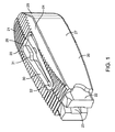
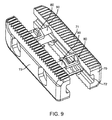
図1は、細長い部材20が2つのスパニング構成要素30によって接続されている椎体間デバイス(移植物とも称される)の好ましい実施形態である。一方は、椎体間デバイスの上側表面に隣接し、他方は、椎体間デバイスの下側表面に隣接している。この実施形態は、1つの構成において、滑らかな壁27が終板に接触している状態で板腔の中に挿入され、頂部および底部表面21が終板に接触する第2の構成へ回転され、次に、滑らかな壁27が第2の構成におけるよりも大きな距離を隔てている第3の構成に、幅に関して拡張されるように設計されている。滑らかな壁27の間の距離は、頂部表面21と底部表面21との間の距離よりも短く、その結果、移植物が第1の構成からへ第2の構成へ回転される場合に、移植物は、板腔を伸延する。移植物のこの実施形態において、スパニング部材は、幅の拡張中に変形するように設計されているので、それらは、変形ゾーン31および32を伴って作製されている。スパニング構成要素30は、それらがそれらの畳まれた状態にある場合、細長い部材20の頂部または底部表面21において形成されている凹んだポケット26の中に嵌っている。頂部および底部表面21は、遊走防止歯を備えており、遊走防止歯は、幅の拡張中、細長い部材20の並進を可能にするが、細長い部材20の長手方向軸に沿ったデバイスの並進を防止することを助ける。細長い部材は、板腔の中へのより容易な導入のためにテーパ状の端部を形成している角度付き表面25を有する。移植物の回転を助けるために、移植物の2つのかどは、面取りされている24。移植物の挿入、回転、および幅の拡張を容易にするために、スロット23および長方形の端部22が、挿入器具と嵌合するように設計されている。
FIG. 1 is a preferred embodiment of an interbody device (also referred to as an implant) in which an
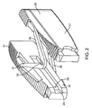
図2は、拡張された構成における移植物を示しており、細長い要素20が互いに対して並進され、スパニング構成要素30がそれらの変形された状態にあり、変形が変形ゾーン31および32において起きている。細長い要素20は、拡張された構成において互いに対して平行であり得るか、または細長い要素20は、互いに対して横断し得る。また、図2において、挿入器具と係合するように設計されている切欠き28が見られる。
FIG. 2 shows the implant in an expanded configuration, with the
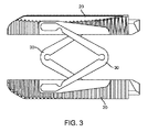
図3は、拡張された状態における移植物の上面図であり、細長い部材およびスパニング構成要素30の両方が明確に見えている。スパニング構成要素(本明細書中でスパニング部材とも称される)30は、互いの対向している端において位置決めされ、均一な拡張のために反対の方向に構成されている。従って、この実施形態において、一方のスパニング構成要素は、1つの方向に開いて角度を形成するヒンジで一緒に接続されている第1のアームと第2のアームとを有し、他方のスパニング構成要素も、他方のスパニング構成要素と反対の方向に開いて角度を形成するヒンジで一緒に接続されている第1のアームと第2のアームとを有する。
FIG. 3 is a top view of the implant in an expanded state, with both the elongated member and the spanning
図4は、移植物から分離されているスパニング構成要素を示している。4つの係合ピン33およびスナップ特徴34は、スパニング構成要素30を細長い部材20に取り付けるように設計されている。
FIG. 4 shows the spanning component being separated from the implant. Four engagement pins 33 and snap features 34 are designed to attach the spanning
図5は、細長い部材20の断面を示しており、スパニング部材30のピン33およびスナップ特徴34と係合する取り付け穴29が示されている。スパニング部材の各アーム上の2つのピンは、接続点における望まれない旋回を防止するために使用される。
FIG. 5 shows a cross section of the
図6は、細長い部材40が2つのスパニング部材50で取り付けられている移植物のさらなる実施形態を示しており、2つのスパニング部材50は、下に記載されるように、スパニング部材50および細長い部材40の両方における嵌合幾何学的形状、ならびに1セットのc−クリップ60を介して、細長い部材40をそれらの拡張された構成に係止する。
FIG. 6 shows a further embodiment of the implant in which the
図7は、テーパ状の端部43と、滑らかな側壁40と、頂部および底部表面42と、器具係合特徴41とを有するその畳まれた状態にある図6の移植物を示している。テーパ状の端部43は、椎間腔の中への挿入を容易にする。
FIG. 7 shows the implant of FIG. 6 in its collapsed state with a tapered end 43,
図8において、図7の断面がスパニング部材50を通して得られ、この図は、c−クリップ60のためのポケット45を有する細長い部材40と、係止溝51を有するスパニング部材とを示している。拡張された幅において、c−クリップ60は、スパニング部材50上の係止溝51の中に係止される。従って、c−クリップは、拡張および収縮し、その結果、それらが係止溝の中に移動する場合、それらは、運動を防止する。また、図8において、第1の構成から第2の構成への回転を容易にすることを助ける湾曲したかど46が見られる。
In FIG. 8, the cross section of FIG. 7 is obtained through the spanning
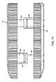
図9は、細長い部材70のより大きな並進を可能にするために、スパニング構成要素80および90が互いに対して入れ子式である移植物の別の例示的実施形態を示している。図9は、滑らかな側壁73と、頂部および底部表面71と、器具係合特徴72とを有するその拡張された状態にあるデバイスを示している。
FIG. 9 illustrates another exemplary embodiment of an implant in which spanning
図10において、拡張された状態における上面図からの図9の実施形態が示されている。第1のスパニング構成要素80におけるスロット82は、第2のスパニング構成要素90を入れ子式にすることを可能にする。スナップ特徴81は、拡張された状態にある場合、第1のスパニング構成要素80および第2のスパニング構成要素90を互いに対して係止する。
In FIG. 10, the embodiment of FIG. 9 from the top view in the expanded state is shown. The
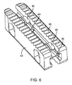
図11は、細長い部材100が、複数の遊走防止歯を有する頂部および底部表面101と、滑らかな側壁103と、器具係合特徴104とを有するさらなる実施形態を示している。椎体間のこの実施形態において、スパニング構成要素110は、4つのラチェッティング部材からなる。畳まれた状態において、スパニング構成要素110は、細長い部材100における滑らかな側壁103に沿って、あり継ぎにされたスロット102の中に位置決めされている。スロット102およびスパニング構成要素110は、スパニング部材110をそれらの対応するスロット102の中に保持するための対応するあり継ぎプロフィールを有する。スパニング部材110は、細長い部材100およびスパニング構成要素110の両方を横断する一連のピン120を介して、細長い部材100に取り付けられている。
FIG. 11 shows a further embodiment in which the
図12は、その拡張された状態における図11の移植物を示している。スパニング構成要素110上のラチェット歯111は、ロック構成要素130と係合して、移植物をその拡張された位置に固定する。ロック構成要素130は、ロック固定ピン140を介して細長い部材100に取り付けられ、ロック固定ピンのヘッドは、畳まれた状態にある場合、細長い部材100における凹部105の中に置かれる。スパニング構成要素110が、畳まれた状態におけるそれらの位置から拡張された状態におけるそれらの位置へ移動するために、スパニング構成要素110は、それらが細長い部材100におけるスロット102の中にある状態から、滑らかな側壁103に対して垂直で、細長い部材100の間で広がっている状態に移行するときに、弾力的に変形することを必要とする。
FIG. 12 shows the implant of FIG. 11 in its expanded state. Ratchet
図13は、図11における移植物の、細長い部材100の内側壁における断面を示している。スパニング構成要素110、ロック130、およびロック固定ピン140が、この断面において見られる。また、ロックがスパニング構成要素110におけるラチェット歯111に沿って歯止めしている接合点131におけるロック130とスパニング部材110との間の相互作用が見られる。
FIG. 13 shows a cross section of the implant in FIG. 11 at the inner wall of the
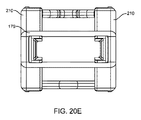
図20A〜図20Eは、他の例示的実施形態の様々な特徴を例示している。図20Aは、畳まれた構成における椎体間固定デバイス(移植物とも称される)の例示的実施形態の斜視図である。移植物は、2つの細長い部材210を含み、2つの細長い部材210は、互いの上に積み重ねられている2つのスパニング部材175で取り付けられている。細長い部材210は、リリーフカット(relief cut)180を含み、このリリーフカット180は、スパニング構成要素を受け取るようなサイズにされ、スパニング構成要素175の負荷を軽減する。レセプタクル181は、本明細書中における他の場所で議論されるように、2つの細長い部材が畳まれた構成にある場合に形成され、外科手術器具が2つの細長い部材に結合されることを可能にする。
20A-20E illustrate various features of other exemplary embodiments. FIG. 20A is a perspective view of an exemplary embodiment of an interbody fusion device (also referred to as an implant) in a collapsed configuration. The implant includes two
図20Bは、細長い部材210を通して得られる図20Aの断面を例示している。この図は、スパニング部材175がどのように細長い部材210に結合されているかを例示している。スパニング部材175上のポスト177および交差ピン176は、スパニング構成要素175を細長い部材210に取り付けるように設計されている。スパニング部材は、凹部180の中に設置されている。
FIG. 20B illustrates the cross section of FIG. 20A taken through the
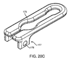
図20Cは、スパニング部材175をより明確に例示している斜視図である。スパニング構成要素175は、ピン176と係合するための2つの係合ポスト177および2つの穴178からなる。スパニング構成要素は、2つのアームから形成され、2つのアームは、アームが開放または閉鎖することを可能にするヒンジで一緒に結合されている。両方のアームにおけるリリーフカットは、アームの自由端が内方または外方に旋回することを可能にし、それにより、それらが、外方に開く場合に細長い部材が互いに対して実質的に平行のままであることを可能にする。
FIG. 20C is a perspective view illustrating the spanning
図20Dは、拡張された構成または伸延された構成における椎体間固定デバイスを例示しており、スパニング構成要素も拡張された構成にある。任意選択の後部キャップ179は、移植物を拡張された構成に係止するために、細長い部材210に結合され得る。外科医は、後部キャップを細長い部材と係合するために、鉗子または別の外科手術器具を使用し得る。後部キャップは、細長い部材への取り付けのために、スナップばめ、プレスばめ、または他の結合機構を有し得る。移植物を拡張された構成に係止することの他に、後部キャップはまた、移植物に安定性を加え、また、骨移植材料の封じ込めを助ける。図20Eは、図20Dにおける移植物の後方図であり、後部キャップ179を強調している。
FIG. 20D illustrates the interbody fusion device in an expanded or distracted configuration, with the spanning component also in the expanded configuration. An
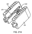
図21A〜図21Gは、移植物の他の例示的実施形態の様々な局面を例示している。図21Aは、拡張された構成における椎体間固定デバイスの斜視図である。移植物は、2つのスパニング部材202で取り付けられている2つの細長い部材201を有する。スパニング部材202は、それらがそれらの畳まれた状態にある場合、細長い部材201の中央に形成されている凹んだポケット203の中に配置される。スパニング部材202は、交差ピン204を介して細長い部材201に取り付けられている。
21A-21G illustrate various aspects of other exemplary embodiments of the implant. FIG. 21A is a perspective view of an interbody fusion device in an expanded configuration. The implant has two
図21Bは、畳まれた構成における図21Aの椎体間固定デバイスを例示している。レセプタクル208は、細長い部材201が畳まれている場合に形成される。レセプタクル208は、他の場所で議論されるように、移植物が他の外科手術器具に結合されることを可能にする。
FIG. 21B illustrates the interbody fusion device of FIG. 21A in a collapsed configuration. The
図21Cは、図21Aにおける実施形態の断面を例示している。断面は、細長い部材201を通して得られる。この図は、細長い部材201、交差ピン204、およびスパニング構成要素202の間の係合を強調している。
FIG. 21C illustrates a cross-section of the embodiment in FIG. 21A. A cross section is obtained through the
図21Dは、図21Aの実施形態からのスパニング構成要素を例示している。2つの穴205は、交差ピン204を嵌めて、移植物に取り付けるように設計されている。この実施形態において、スパニング部材は、変形ゾーン206において変形し、幅の拡張中、交差ピン204の周りを旋回するように設計されている。交差部材(スパニング部材とも称される)は、ヒンジで一緒に結合されている2つのアームを含む。各アームの自由端は、ピンを受け取るための穴205を含む。
FIG. 21D illustrates the spanning component from the embodiment of FIG. 21A. The two
図21Eは、図21Aの実施形態における2つのスパニング部材202の互いに対する配向を例示している。この実施形態において、上方スパニング部材は、第1の方向に向いている開放端と閉鎖端とを有する。下方スパニング部材は、第1の方向と反対の第2の方向に向いている開放端と閉鎖端とを有する。ピン204も各スパニング部材の穴において示されている。
FIG. 21E illustrates the orientation of the two spanning
図21Fは、図21Aの椎体間固定デバイスの代替の実施形態を例示している。図21Aの実施形態において、細長い部材における穴および各スパニング部材のためのピンは、細長い部材の同じ側面上に配置されている。図21Fにおいて、1つの穴が、移植物の上側表面上にあり、第2の穴が、移植物の下側表面上にある。従って、対応するピンも、移植物の対向する側面から押し込まれる。一方は、上側表面から押し込まれ、他方は、下側表面から押し込まれる。同様に、第2のスパニング部材は、細長い部材の各側面から押し込まれる1つのピンを有する。 FIG. 21F illustrates an alternative embodiment of the interbody fusion device of FIG. 21A. In the embodiment of FIG. 21A, the holes in the elongate member and the pins for each spanning member are located on the same side of the elongate member. In FIG. 21F, one hole is on the upper surface of the implant and the second hole is on the lower surface of the implant. Accordingly, the corresponding pin is also pushed from the opposite side of the implant. One is pushed from the upper surface and the other is pushed from the lower surface. Similarly, the second spanning member has one pin that is pushed from each side of the elongated member.
図21Gは、図21Fにおける実施形態の上面図を例示しており、互い違いのピン構成を有する。 FIG. 21G illustrates a top view of the embodiment in FIG. 21F and has a staggered pin configuration.
図22A〜図22Dは、椎体間固定デバイスの別の例示的実施形態の局面を例示している。図22Aは、畳まれた構成における移植物の斜視図を例示している。ここで、細長い部材209は、1つのスパニング部材202のみで取り付けられている。スパニング部材202は、それらがそれらの畳まれた状態にある場合、細長い部材209の各々の中央に形成されている凹んだポケット203の中に嵌っている。スパニング部材202は、交差ピン204を介して細長い部材201に取り付けられている。
22A-22D illustrate aspects of another exemplary embodiment of an interbody fusion device. FIG. 22A illustrates a perspective view of the implant in a collapsed configuration. Here, the
図22Bは、図22Aにおける椎体間固定デバイスの上面図を例示している。図22Cは、細長い部材201の断面を示しており、細長い部材209、交差ピン204、およびスパニング部材202の間の係合を示している。
FIG. 22B illustrates a top view of the interbody fusion device in FIG. 22A. FIG. 22C shows a cross-section of the
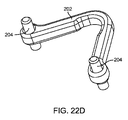
図22Dは、ヒンジで一緒に接続されている2つのアームを含むスパニング部材202を例示している。アームの自由端は、ピン204を受け取るための穴を含む。
FIG. 22D illustrates a spanning
図23A〜図23Eは、椎体間固定デバイスの別の例示的実施形態の特徴を例示している。図23Aは、畳まれた構成における椎体間固定デバイスの斜視図を例示している。この実施形態において、細長い部材211は、2つのスパニング部材212で一緒に結合されている。レセプタクル214は、本明細書中における他の場所で議論されるように、移植物が送達のために外科手術器具と係合されることを可能にする。移植物の上側表面および下側表面は、任意選択で、移動防止(anti−movement)歯を有し、この特徴は、本明細書中に開示される移植物の実施形態のうちの任意のものにおいて、任意選択で含まれ得る。
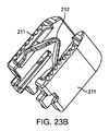
23A-23E illustrate features of another exemplary embodiment of an interbody fusion device. FIG. 23A illustrates a perspective view of an interbody fusion device in a collapsed configuration. In this embodiment, the
図23Bは、拡張された構成における図23Aの移植物を例示している。図23Cは、拡張された構成における図23Aにおける移植物の断面を示している。断面は、スパニング構成要素212を通して得られる。交差ピン213は、スパニング構成要素212を細長い部材211に取り付け、細長い部材211の長手方向軸の周りでの旋回運動を可能にする。
FIG. 23B illustrates the implant of FIG. 23A in an expanded configuration. FIG. 23C shows a cross-section of the implant in FIG. 23A in an expanded configuration. A cross section is obtained through the spanning
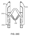
図23Dは、スパニング部材212をより詳細に例示している。スパニング部材212は、ヒンジで一緒に接続されている2つのアームを含む。アームの自由端は、各々が、スパニング部材212を細長い部材に固定するための交差ピン213を受け取るための穴216を有する。主要ヒンジの他に、各アームは、二次的ヒンジ215を形成している弓形切り抜き領域を有する。二次的ヒンジは、例えば、細長い部材が外方に拡張する場合に細長い部材が実質的に平行の構成のままであり得る場合において、アームが主要ヒンジから独立してさらに屈曲することを可能にする。
FIG. 23D illustrates the spanning
図23Eは、両方のスパニング部材を例示しており、両方のスパニング部材は、それらが図23Aの移植物におけるものであるように、互いの上に積み重ねられており、交差ピンが穴216の中に挿入されている。各スパニング部材における両方のアームの一部分は、主要ヒンジで角度を形成し、二次的ヒンジは、アームの自由端がアームの対向する自由端に向かって内方に屈曲することを可能にし、それにより、両方のアームの自由端が互いに対して実質的に平行のままであることを可能にする。これは、細長い部材が、拡張された構成において、互いに対して実質的に平行のままであることも可能にする。 FIG. 23E illustrates both spanning members, both spanning members being stacked on top of each other so that they are in the implant of FIG. Has been inserted. A portion of both arms in each spanning member forms an angle with the primary hinge, and the secondary hinge allows the free ends of the arms to bend inwardly toward the opposite free ends of the arms, which This allows the free ends of both arms to remain substantially parallel to each other. This also allows the elongated members to remain substantially parallel to each other in the expanded configuration.
移植。 Transplant.
図14は、上側椎体150と、下側椎体160と、それらの間の椎間腔180とを示している。下側椎体160の上関節突起161および上側椎体150の下関節突起151は、経椎間孔椎体間固定手順(TLIF)において一般的であるように、椎間腔の中へのアクセスを可能にするために、1つの側面において除去されている。図14は、滑らかな側壁が椎体150および160の終板に接触している状態で椎間腔180の中に挿入されている移植物170を示している。移植物170は、本明細書中に開示される移植物の実施形態のうちの任意のものであり得る。
FIG. 14 shows an upper
図15は、移植物172の頂部および底部表面が椎体の終板に接触するように90度回転されている移植物を示している。移植物の幅に対する移植物の高さの差に起因して、この回転は、椎体150および160の伸延をもたらす。
FIG. 15 shows the implant rotated 90 degrees so that the top and bottom surfaces of the
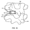
図16は、拡張された状態における移植物170を示しており、移植物のために、より広くより安定した設置面積を作り出し、移植物173の中に作り出される空間への移植材料の挿入のために、十分な余地を作り出している。移植のこの例示的な方法における移植物は、本明細書中に記載されるもののうちの任意のものであり得る。
FIG. 16 shows the
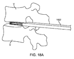
図18A〜図18Fは、挿入ガイドデバイス(例えば、図17において例示されるもの)を用いて、椎体間移植物を送達する例示的な方法を例示している。 18A-18F illustrate an exemplary method of delivering an interbody implant using an insertion guide device (eg, as illustrated in FIG. 17).
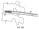
図18Aにおいて、挿入ガイドデバイス1802は、隣接する椎骨Vの間の椎間板腔の中に挿入されている。図18Bにおいて、椎体間移植物1804は、図18Cにおいて例示されるように、それが、挿入ガイドデバイスの拡張可能な部分から露出され、椎骨の間の所望の場所に位置決めされるまで、挿入ガイドデバイス1802の外に遠位方向に前進される。移植物の上方および下方表面の遊走防止歯は、外側方向外方および内側方向外方に向いており、滑らかな外側表面は、上向きおよび下向きに向いており、椎骨の終板を係合している。図18Dは、図18Cと同様であるが、挿入ガイドデバイスのより長い部分を例示している。
In FIG. 18A, an
図18Eにおいて、椎体間移植物および挿入ガイドデバイスは、椎体間移植物のテクスチャー付加された(textured)表面が椎骨の終板と係合するように90度回転されており、次に、移植物の滑らかな外側表面が、外側方向外方および内側方向外方に向いている。図18Fは、椎体間移植物および挿入ガイドデバイスの上面図であり、見ることを容易にするために上方椎骨が除去されている。さらに、椎体間移植物は、その幅を増大するために側方に拡張されている。移植物および挿入ガイドデバイスは、本明細書中に開示される実施形態のうちの任意のものであり得る。 In FIG. 18E, the interbody implant and insertion guide device have been rotated 90 degrees so that the textured surface of the interbody implant engages the endplate of the vertebra, The smooth outer surface of the implant faces outwardly outward and inwardly outward. FIG. 18F is a top view of the interbody implant and insertion guide device with the upper vertebra removed for ease of viewing. In addition, the interbody implant has been laterally expanded to increase its width. The implant and insertion guide device can be any of the embodiments disclosed herein.
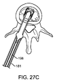
図27A〜図27Cは、移植物の送達および配備の他の局面を例示している。図27Aは、下側椎体198において挿入器具183と係合されている移植物の上面図を示している。上側椎骨は、便宜上、図から省略されている。移植物は、滑らかな側壁199が終板に接触している状態で椎間板腔の中に挿入されている。挿入ツールは、移植物を送達するために使用され得るか、または挿入ツールは、以前に上で記載された挿入ガイドとともに使用され得る。
27A-27C illustrate other aspects of implant delivery and deployment. FIG. 27A shows a top view of the implant engaged with the
図27Bは、移植物の頂部および底部表面200が椎体の終板に接触するように90度回転されている移植物を示している。頂部および底部表面は、好ましくは、望まれない移動を防止するために、遊走防止歯を有する。回転は、挿入ツールを回転することによって達成される。
FIG. 27B shows the implant rotated 90 degrees so that the top and
図27Cは、挿入ツールから係合解除され、次に拡張器具と係合している椎体間固定デバイスを示している。拡張器具は、遠位方向に前進されており、それにより、移植物を拡張された構成へ拡張している。拡張器具187およびシム181は、依然として移植物に結合されている。適切な位置決めおよび拡張が確認された後、拡張器具およびシムは、取り外され得る。
FIG. 27C shows the interbody fusion device disengaged from the insertion tool and then engaged with the dilator. The dilator has been advanced distally, thereby expanding the implant into an expanded configuration. The
外科手術器具。 Surgical instruments.
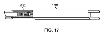
図17は、挿入ガイドデバイス1794に結合されている椎体間移植物1792を例示している。椎体間移植物は、その畳まれた構成にあり、それは、本明細書中に開示される実施形態のうちの任意のものであり得る。挿入ガイドデバイスは、本明細書中に開示されるか、または2014年7月2日に出願された米国特許出願第14/322,589号(代理人番号44057−705.201)(以前に本明細書中で参考として援用された)に開示される実施形態のうちの任意のものであり得る。挿入ガイドデバイスは、好ましくは、1対の細長い挿入プレートを含み、弾性部材がそれを覆って配置されている。移植物は、細長い挿入プレートによって形成されているチャネルを通過し、弾性部材は、拡張して移植物を収容する。
FIG. 17 illustrates an
図19A〜図19Bは、以前に記載された挿入ガイドデバイスを通して椎体間移植物を移動するために、操作者によって前進または後退され得るプッシャー要素を例示している。図19Aにおいて、プッシャー要素1902は、細長いシャフトを含み、ハンドルが、操作を容易にするために近位端にある。レバー1904は、プッシャーを椎体間移植物に係止することを助ける。図19Bは、プッシャー要素1902に結合されている椎体間移植物1906を例示している。板ばねが作動レバーの下に配置され、それにより、プッシャーが椎体間移植物と係止されたままであるように、レバーを上がった位置へ付勢している。レバーが移動される場合、移植物は、プッシャーから分離され得る。
19A-19B illustrate a pusher element that can be advanced or retracted by an operator to move an interbody implant through a previously described insertion guide device. In FIG. 19A,
図24A〜図24Cは、挿入器具に沿って移植物を前進するために使用されるシムとの椎体間固定デバイスの係合を例示している。図24Aは、本明細書中に記載される椎体間固定デバイスのうちの任意のものを係合するために使用されるシムの斜視図を例示している。シム181は、細長いシャフトを含み、細長いシャフトの遠位部分において嵌合特徴182を有し、それは、任意の椎体間固定デバイス(例えば、図2において見られるような切欠き28)、または本明細書中に記載されるレセプタクルのうちの任意のもの(例えば、図23Aにおけるレセプタクル214)と係合するように構成されている。シムの近位端は、挿入ツールとの係合のための切欠きを含む。
24A-24C illustrate the engagement of the interbody fusion device with a shim used to advance the implant along the insertion tool. FIG. 24A illustrates a perspective view of a shim used to engage any of the interbody fusion devices described herein. The
図24Bは、本明細書中に開示される任意の椎体間固定デバイスとのシム181の係合を示している。シムにおける嵌合特徴182は、移植物における、対応する切欠き、レセプタクル、または他の嵌合特徴と解放可能に結合される。
FIG. 24B illustrates the engagement of
図24Cは、断面をより詳細に例示し、移植物とのシム181の嵌合特徴182の係合を示している。ここで、2つのシム181が例示されている。シム181は、移植物のスロット23の中に嵌り、切欠き28において移植物と係合する。この実施形態におけるシムの嵌合特徴は、移植物の中および対応するレセプタクルの中に前進されるように構成されている角度付き突出部を有する拡大されたヘッドを含むが、角度付き突出部の平らな部分を係合してそれが引き抜かれることを防止する平らなショルダーをレセプタクルが有するので、移植物が畳まれた構成にある場合、容易には引き抜かれ得ない。
FIG. 24C illustrates the cross-section in more detail and illustrates the engagement of the
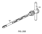
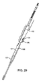
図25A〜図25Bは、本明細書中に記載される椎体間固定デバイスのうちの任意のものを処置部位に送達するための、以前に上で記載されたシムとともに使用され得る挿入ツールの例示的実施形態を例示している。挿入器具183は、近位端と遠位端とを有する細長いシャフトを含む。半径方向外方に延びてT−形状のハンドルを形成している複数のポスト185を有するハンドルが、細長いシャフトの近位部分上に配置されている。近位部分と遠位部分との間のシャフトの中央部分は、長方形または正方形であり得、デバイスの重量を減らすために、およびまた、シャフト中に配置されている中央チャネルを通過する構成要素を操作者が見ることを可能にするために、シャフトの壁を通過している切り抜きを有する。シャフトの遠位部分は、円筒形部分を有し得る。挿入器具183は、以前に上で記載されたシム(例えば、図24Aにおけるシム181)との係合を可能にするスロット184からなる。ハンドルは、操作者が挿入器具を操作すること(器具を回転することが挙げられる)を可能にする。係合特徴186は、移植物(例えば、図1における長方形の端部22)と嵌合するように構成されている。
25A-25B illustrate an insertion tool that can be used with the previously described shim for delivering any of the interbody fusion devices described herein to a treatment site. 2 illustrates an exemplary embodiment. The
図25Bは、椎体間固定デバイス(例えば、本明細書中に記載されるもののうちの任意のもの)と係合されている図25Aの挿入器具を例示している。シムは、移植物に結合されており、それらは、細長いシャフトの中央チャネルの中に配置されている。 FIG. 25B illustrates the insertion instrument of FIG. 25A engaged with an interbody fusion device (eg, any of those described herein). The shims are coupled to the implant and they are placed in the central channel of the elongated shaft.
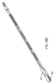
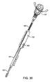
図26A〜図26Eは、移植物を畳まれた構成から拡張された構成または伸延された構成に拡張するために使用される拡張ツールのいくつかの実施形態の様々な特徴を例示している。図26Aは、拡張器具187の斜視図を示している。拡張器具187は、近位端と遠位端とを有する細長いシャフトを含む。近位端の近くで、スロット188が、以前に上で開示されたシムを係合するチャネルを形成するように構成されている。細長いシャフトは、ハンドル(例えば、図26Bに見られるものであり、移植物の拡張中に使用される)と係合し得る長方形のシャフト191を含む。拡張器具187は、移植物の細長い部材の間へのより容易な導入のためにテーパ状の端部を形成している角度付き表面189を有する。ねじ切りされた構成要素190は、移植物の制御された拡張を可能にする。
FIGS. 26A-26E illustrate various features of several embodiments of an expansion tool used to expand an implant from a collapsed configuration to an expanded or distracted configuration. FIG. 26A shows a perspective view of the
図26Bは、図26Aにおける拡張器具とともに使用され得るハンドルの斜視図を例示している。ハンドルは、ねじ切りされた構成要素190と係合するための嵌合ねじ筋193を含み、長方形のスロット194は、ハンドルを通した拡張器具187の長方形のシャフト191の並進を可能にする。スロット196は、シム181の挿入を可能にし、ボタン195は、シム181をハンドル192と係合する。
FIG. 26B illustrates a perspective view of a handle that may be used with the expansion device in FIG. 26A. The handle includes a
図26Cは、移植物と係合されている拡張器具の斜視図を例示している。移植物が椎間板腔の中に挿入された後、挿入ツールが取り外され、移植物およびシムを所定の位置に残す。次に、シムおよび移植物は、見られるように、拡張器具に結合され、ハンドル192および手掌ハンドル197も拡張器具に取り付けられる。図26Cは、一度拡張が完了した移植物を示している。シム181は、移植物、拡張器具187、およびハンドル192と係合されて示されている。拡張器具187はまた、ハンドル192および手掌ハンドル197と係合されて示されている。それを前方または遠位方向に押すことによる手掌ハンドル197の作動は、移植物の細長い部材の間の拡張器具187を駆動して、それらの拡張をもたらすために使用される。
FIG. 26C illustrates a perspective view of the expansion device engaged with the implant. After the implant is inserted into the disc space, the insertion tool is removed, leaving the implant and shim in place. The shim and implant are then coupled to the dilator as seen, and the
図26Dは、シム、拡張器具、および移植物の係合を強調し、拡張された構成への移植物の拡張を示している。 FIG. 26D highlights the engagement of the shim, expansion device, and implant, and illustrates the expansion of the implant into an expanded configuration.
図26Eは、別の拡張器具207の代替の実施形態の斜視図を例示している。拡張器具207は、中央に位置しているスパニング部材の周りで並進するためのスロット208を有する。
FIG. 26E illustrates a perspective view of an alternative embodiment of another
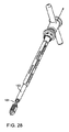
図28〜図32は、椎体間移植物を挿入し、配備するための様々な器具の使用をより明確に例示している。図28は、移植物が90度回転された後の移植物からの挿入器具183の取り外しを示しており、シム181が移植物に取り付けられているままである。
Figures 28-32 more clearly illustrate the use of various instruments for inserting and deploying interbody implants. FIG. 28 shows the removal of the
図29は、拡張器具187および拡張ハンドル192とのシム181の係合を示している。シム181は、拡張器具187のスロット188および拡張ハンドル192のスロット196を通ってスライドし、ここでボタン195がシム181を適所に係止する。
FIG. 29 illustrates the engagement of the
図30は、迅速接続を介したハンドル197の係合を示している。拡張器具187は、ねじ切りされた構成要素190が拡張ハンドル192と係合するまで、移植物に向かってスライドする。次に、ハンドル197は、図31において示されるように、拡張器具187を移植物に向かって駆動し、シム181を分離し、それにより、移植物の細長い部材を分離するために使用される。拡張器具の最終位置は、図26Cにおいて見られ得る。次に、拡張器具は、ねじ切りされた構成要素190がもはや拡張ハンドル192と係合しなくなるまで構成要素190を移植物から離れる方へ駆動することによって、係合解除され得る。ボタン195を押圧することは、シム181を係合解除し、ユーザーが拡張器具を移植物から離れる方へスライドすることを可能にし、図32において示されるように、拡張された移植物およびシム181を適所に残す。
FIG. 30 illustrates the engagement of the
図31は、シム181を分離し、それにより、移植物の細長い部材を分離する拡張器具187を示している。
FIG. 31 shows an
図32は、拡張後、および拡張器具が取り外された後のシム181および移植物を示している。次に、シム181は、それらを対応する細長い部材から離れる方へ引っ張ることによって係合解除され得、移植物を拡張された構成に残す。
FIG. 32 shows the
本発明の好ましい実施形態が本明細書中に示され、記載されてきたが、そのような実施形態が例としてのみ提供されることが当業者に明らかである。次に、数多くのバリエーション、変更、および代用物が、本発明から外れることなく当業者に見出される。本明細書中に記載される本発明の実施形態に対する様々な代替物が、本発明を実施することにおいて用いられ得ることが理解されるべきである。以下の特許請求の範囲が本発明の範囲を規定すること、ならびにこれらの特許請求の範囲の範囲内の方法および構造、およびそれらの等価物がそれにより含まれることが意図される。 While preferred embodiments of the present invention have been shown and described herein, it will be apparent to those skilled in the art that such embodiments are provided by way of example only. Numerous variations, modifications, and substitutions will now be found to those skilled in the art without departing from the invention. It should be understood that various alternatives to the embodiments of the invention described herein can be used in practicing the invention. It is intended that the following claims define the scope of the invention and that methods and structures within the scope of these claims and their equivalents be thereby included.
Claims (48)
該移植物を形成している1つ以上の細長い部材を含み、該1つ以上の細長い部材は、間に高さを有する上側表面および下側表面と、間に幅を有する内側表面および外側表面とを有し、
該上側表面および該下側表面は、該椎体を係合するような形状にされ、
該高さは、該椎間腔の中に嵌るようなサイズにされている所定の距離に設定され、
該幅は、該所定の高さよりも短い所定の距離に設定され、
該椎体間移植物は、第1の構成と、第2の構成と、第3の構成とを有し、
該椎体間移植物は、該第1の構成において、内側表面および外側表面が該椎体に接触するように該椎間腔の中に挿入され、
該椎体間移植物は、上側表面および下側表面が該椎体を係合するように該第2の構成へ作動され、該第1の構成から該第2の構成への該移植物の作動は、該椎体を互いから離れる方へ伸延して、該椎間腔を増大し、
該移植物は、移植物の幅が該第1の構成または該第2の構成における椎体間移植物の幅よりも大きい該第3の構成へ作動される、移植物。 An interbody implant for implantation in a patient during a spinal fusion into an intervertebral space surrounded by adjacent vertebral bodies, the implant comprising:
One or more elongate members forming the implant, the one or more elongate members having upper and lower surfaces having a height therebetween, and inner and outer surfaces having a width therebetween And
The upper surface and the lower surface are shaped to engage the vertebral body;
The height is set to a predetermined distance that is sized to fit within the intervertebral space;
The width is set to a predetermined distance shorter than the predetermined height;
The interbody implant has a first configuration, a second configuration, and a third configuration;
The interbody implant is inserted into the intervertebral space in the first configuration such that the inner and outer surfaces contact the vertebral body;
The interbody implant is actuated to the second configuration such that the upper surface and the lower surface engage the vertebral body, and the implant of the implant from the first configuration to the second configuration Actuation extends the vertebral bodies away from each other, increasing the intervertebral space,
The implant wherein the implant is actuated to the third configuration where the width of the implant is greater than the width of the interbody implant in the first configuration or the second configuration.
前記第2の構成から前記第3の構成への前記移植物の作動は、互いから離れる方への該2つの細長い部材の並進によって得られる、請求項1に記載の移植物。 The one or more elongated members include two elongated members;
The implant of claim 1, wherein actuation of the implant from the second configuration to the third configuration is obtained by translation of the two elongate members away from each other.
該移植物を形成している複数の細長い部材であって、該複数の細長い部材は、間に高さを有する上側表面および下側表面と、間に幅を有する内側表面および外側表面とを有する、複数の細長い部材と、
該複数の細長い部材に結合されている1つ以上のスパニング部材と
を含み、該上側表面および該下側表面は、該椎体を係合するような形状にされ、
該高さは、該椎間腔の中に嵌るようなサイズにされている所定の距離に設定され、
該幅は、該所定の高さよりも短い所定の距離に設定され、
該椎体間移植物は、第1の構成と、第2の構成と、第3の構成とを有し、
該椎体間移植物は、該第1の構成において、内側表面および外側表面が該椎体に接触するように該椎間腔の中に挿入され、
該椎体間移植物は、該上側表面および該下側表面が該椎体を係合し、該椎体を互いから離れる方へ伸延するように該第2の構成へ作動され、
該第3の構成において、幅は、該第1の構成または該第2の構成における幅よりも大きく、該第2の構成から該第3の構成への作動は、互いから側方に離れる方への該1つ以上の細長い部材の並進を含む、移植物。 An interbody implant for implantation in a patient during a spinal fusion into an intervertebral space surrounded by adjacent vertebral bodies, the implant comprising:
A plurality of elongate members forming the implant, the plurality of elongate members having upper and lower surfaces having a height therebetween, and inner and outer surfaces having a width therebetween. A plurality of elongated members;
One or more spanning members coupled to the plurality of elongated members, wherein the upper surface and the lower surface are shaped to engage the vertebral body,
The height is set to a predetermined distance that is sized to fit within the intervertebral space;
The width is set to a predetermined distance shorter than the predetermined height;
The interbody implant has a first configuration, a second configuration, and a third configuration;
The interbody implant is inserted into the intervertebral space in the first configuration such that the inner and outer surfaces contact the vertebral body;
The interbody implant is actuated to the second configuration such that the upper surface and the lower surface engage the vertebral body and extend the vertebral body away from each other;
In the third configuration, the width is greater than the width in the first configuration or the second configuration, and the operation from the second configuration to the third configuration is laterally away from each other. An implant comprising translation of the one or more elongate members into the body.
第1の構成において、椎体間移植物を該椎間腔の中に挿入することと、
該椎体間移植物が第2の構成にある場合に該椎体間移植物が該椎間腔をより高い高さに伸延するように、該椎体間移植物を該第1の構成から該第2の構成に作動することと、
該椎体間移植物を該第2の構成から第3の構成に作動することと
を含み、該第3の構成において、移植物の幅は、該第1の構成における移植物の幅に対して増大している、方法。 A method for delivering an interbody implant into a patient's intervertebral space, the method comprising:
In a first configuration, inserting an interbody implant into the intervertebral space;
The interbody implant is removed from the first configuration such that the interbody implant extends the intervertebral space to a higher height when the interbody implant is in the second configuration. Operating in the second configuration;
Actuating the interbody implant from the second configuration to a third configuration, wherein the width of the implant is relative to the width of the implant in the first configuration The method is growing.
該椎体間移植物を細長いシムと結合することと、
該細長いシムを挿入器具と結合することと、
該挿入器具を該椎間腔に向かって前進することと、
該椎体間移植物を該椎間腔の中に配置することと
を含む、請求項33に記載の方法。 The first configuration includes a collapsed configuration, and in the collapsed configuration, inserting the interbody implant into the intervertebral space comprises:
Combining the interbody implant with an elongated shim;
Coupling the elongated shim with an insertion instrument;
Advancing the insertion instrument toward the intervertebral space;
34. The method of claim 33, comprising placing the interbody implant in the intervertebral space.
前記挿入器具を前記細長いシムから切り離すことと、
拡張器具を該細長いシムと結合することと、
該拡張器具のウェッジ形部分を該椎体間移植物の中に前進し、それにより、該椎体間移植物を拡張することと
を含む、請求項42に記載の方法。 Actuating the interbody implant from the second configuration to the third configuration comprises:
Detaching the insertion instrument from the elongated shim;
Coupling an expansion device with the elongated shim;
43. The method of claim 42, comprising advancing a wedge-shaped portion of the dilator device into the interbody implant, thereby expanding the interbody implant.
椎体間固定デバイスと、
近位端と遠位端とを有する細長いシムと
を含み、該遠位端は、該椎体間固定デバイスを解放可能に結合するための係合要素を含み、該近位端は、外科手術器具を係合するように構成されている、システム。 A system for delivering an interbody implant into a patient's intervertebral space, the system comprising:
An interbody fusion device;
An elongate shim having a proximal end and a distal end, the distal end including an engaging element for releasably coupling the interbody fusion device, the proximal end A system configured to engage an instrument.
Applications Claiming Priority (5)
| Application Number | Priority Date | Filing Date | Title |
|---|---|---|---|
| US201361842888P | 2013-07-03 | 2013-07-03 | |
| US61/842,888 | 2013-07-03 | ||
| US14/322,702 | 2014-07-02 | ||
| US14/322,702 US10265192B2 (en) | 2013-07-03 | 2014-07-02 | Methods and apparatus for implanting an interbody device |
| PCT/US2014/045490 WO2015003173A2 (en) | 2013-07-03 | 2014-07-03 | Methods and apparatus for implanting an interbody device |
Related Child Applications (1)
| Application Number | Title | Priority Date | Filing Date |
|---|---|---|---|
| JP2018244110A Division JP2019048196A (en) | 2013-07-03 | 2018-12-27 | Methods and apparatus for implanting interbody device |
Publications (2)
| Publication Number | Publication Date |
|---|---|
| JP2016526455A true JP2016526455A (en) | 2016-09-05 |
| JP2016526455A5 JP2016526455A5 (en) | 2017-08-10 |
Family
ID=52133344
Family Applications (3)
| Application Number | Title | Priority Date | Filing Date |
|---|---|---|---|
| JP2016524386A Pending JP2016526455A (en) | 2013-07-03 | 2014-07-03 | Method and apparatus for implanting an interbody device |
| JP2018244110A Pending JP2019048196A (en) | 2013-07-03 | 2018-12-27 | Methods and apparatus for implanting interbody device |
| JP2020117036A Pending JP2020168463A (en) | 2013-07-03 | 2020-07-07 | Methods and apparatus for implanting interbody device |
Family Applications After (2)
| Application Number | Title | Priority Date | Filing Date |
|---|---|---|---|
| JP2018244110A Pending JP2019048196A (en) | 2013-07-03 | 2018-12-27 | Methods and apparatus for implanting interbody device |
| JP2020117036A Pending JP2020168463A (en) | 2013-07-03 | 2020-07-07 | Methods and apparatus for implanting interbody device |
Country Status (4)
| Country | Link |
|---|---|
| US (3) | US10265192B2 (en) |
| EP (1) | EP3016617B1 (en) |
| JP (3) | JP2016526455A (en) |
| WO (1) | WO2015003173A2 (en) |
Cited By (1)
| Publication number | Priority date | Publication date | Assignee | Title |
|---|---|---|---|---|
| JP2018029947A (en) * | 2016-06-29 | 2018-03-01 | グローバス メディカル インコーポレイティッド | Expandable fusion device and method of installation thereof |
Families Citing this family (77)
| Publication number | Priority date | Publication date | Assignee | Title |
|---|---|---|---|---|
| US8105382B2 (en) | 2006-12-07 | 2012-01-31 | Interventional Spine, Inc. | Intervertebral implant |
| US8900307B2 (en) | 2007-06-26 | 2014-12-02 | DePuy Synthes Products, LLC | Highly lordosed fusion cage |
| AU2009205896A1 (en) | 2008-01-17 | 2009-07-23 | Synthes Gmbh | An expandable intervertebral implant and associated method of manufacturing the same |
| EP2262449B1 (en) | 2008-04-05 | 2020-03-11 | Synthes GmbH | Expandable intervertebral implant |
| US9724140B2 (en) | 2010-06-02 | 2017-08-08 | Wright Medical Technology, Inc. | Tapered, cylindrical cruciform hammer toe implant and method |
| US8608785B2 (en) | 2010-06-02 | 2013-12-17 | Wright Medical Technology, Inc. | Hammer toe implant with expansion portion for retrograde approach |
| US9498273B2 (en) | 2010-06-02 | 2016-11-22 | Wright Medical Technology, Inc. | Orthopedic implant kit |
| DE102010047901B4 (en) * | 2010-10-11 | 2019-01-10 | Heinrich Böhm | Implant for the spine and operating instrument |
| US9308099B2 (en) | 2011-02-14 | 2016-04-12 | Imds Llc | Expandable intervertebral implants and instruments |
| US9393126B2 (en) * | 2012-04-20 | 2016-07-19 | Peter L. Mayer | Bilaterally placed disc prosthesis for spinal implant and method of bilateral placement |
| US9364339B2 (en) * | 2012-04-30 | 2016-06-14 | Peter L. Mayer | Unilaterally placed expansile spinal prosthesis |
| EP3281609B1 (en) | 2012-05-29 | 2019-02-27 | NLT Spine Ltd. | Expanding implant |
| US8663332B1 (en) | 2012-12-13 | 2014-03-04 | Ouroboros Medical, Inc. | Bone graft distribution system |
| US8945232B2 (en) | 2012-12-31 | 2015-02-03 | Wright Medical Technology, Inc. | Ball and socket implants for correction of hammer toes and claw toes |
| US9717601B2 (en) | 2013-02-28 | 2017-08-01 | DePuy Synthes Products, Inc. | Expandable intervertebral implant, system, kit and method |
| US9522070B2 (en) | 2013-03-07 | 2016-12-20 | Interventional Spine, Inc. | Intervertebral implant |
| WO2014145939A2 (en) | 2013-03-15 | 2014-09-18 | Spectrum Spine Ip Holdings, Llc | Expandable inter-body fusion devices and methods |
| US9333093B2 (en) * | 2013-05-13 | 2016-05-10 | Kamran Aflatoon | Minimally invasive expandable interbody fusion cage |
| WO2014189890A1 (en) | 2013-05-20 | 2014-11-27 | K2M, Inc. | Adjustable implant and insertion tool |
| US9788971B1 (en) | 2013-05-22 | 2017-10-17 | Nuvasive, Inc. | Expandable fusion implant and related methods |
| US9408721B2 (en) | 2013-07-03 | 2016-08-09 | Spine Innovation, Llc | Methods and apparatus for an insertion guide device |
| US10265192B2 (en) | 2013-07-03 | 2019-04-23 | Spine Innovation, Llc | Methods and apparatus for implanting an interbody device |
| US9186259B2 (en) | 2013-09-09 | 2015-11-17 | Ouroboros Medical, Inc. | Expandable trials |
| US9724139B2 (en) | 2013-10-01 | 2017-08-08 | Wright Medical Technology, Inc. | Hammer toe implant and method |
| US9474561B2 (en) | 2013-11-19 | 2016-10-25 | Wright Medical Technology, Inc. | Two-wire technique for installing hammertoe implant |
| US9545283B2 (en) * | 2013-12-23 | 2017-01-17 | Jmea Corporation | Devices and methods for preparation of vertebral members |
| US9730802B1 (en) * | 2014-01-14 | 2017-08-15 | Nuvasive, Inc. | Spinal fusion implant and related methods |
| US9545274B2 (en) * | 2014-02-12 | 2017-01-17 | Wright Medical Technology, Inc. | Intramedullary implant, system, and method for inserting an implant into a bone |
| US9498266B2 (en) | 2014-02-12 | 2016-11-22 | Wright Medical Technology, Inc. | Intramedullary implant, system, and method for inserting an implant into a bone |
| JP6235724B2 (en) | 2014-09-18 | 2017-11-22 | ライト メディカル テクノロジー インコーポレイテッドWright Medical Technology, Inc. | Spider toe implant and tool |
| US9585762B2 (en) | 2014-10-09 | 2017-03-07 | K2M, Inc. | Expandable spinal interbody spacer and method of use |
| CA2889595C (en) | 2014-12-19 | 2018-01-16 | Wright Medical Technology, Inc. | Intramedullary anchor for interphalangeal arthrodesis |
| US9060876B1 (en) | 2015-01-20 | 2015-06-23 | Ouroboros Medical, Inc. | Stabilized intervertebral scaffolding systems |
| US11426290B2 (en) * | 2015-03-06 | 2022-08-30 | DePuy Synthes Products, Inc. | Expandable intervertebral implant, system, kit and method |
| JP6949725B2 (en) | 2015-05-12 | 2021-10-13 | ニューヴェイジヴ,インコーポレイテッド | Expandable lordotic face implant |
| US9814602B2 (en) * | 2015-05-14 | 2017-11-14 | Globus Medical, Inc. | Expandable intervertebral implants and methods of installation thereof |
| JP6949006B2 (en) | 2015-08-25 | 2021-10-13 | アイエムディーエス リミテッド ライアビリティ カンパニー | Expandable facet implant |
| EP3397212A1 (en) | 2015-12-30 | 2018-11-07 | Nuvasive, Inc. | Lordotic expandable fusion implant |
| US10004608B2 (en) * | 2016-02-26 | 2018-06-26 | K2M, Inc. | Insertion instrument for expandable spinal implants |
| TWI589266B (en) * | 2016-03-14 | 2017-07-01 | 曾昌和 | Spinal implant structure and kit thereof |
| US11253369B2 (en) * | 2016-03-14 | 2022-02-22 | Wiltrom Co., Ltd. | Spinal implant structure and kit thereof |
| EP3222251B1 (en) * | 2016-03-21 | 2018-12-05 | 41Medical AG | Expandable spinal implant |
| AU2017287886B2 (en) | 2016-06-28 | 2022-07-28 | Eit Emerging Implant Technologies Gmbh | Expandable, angularly adjustable intervertebral cages |
| US11596523B2 (en) | 2016-06-28 | 2023-03-07 | Eit Emerging Implant Technologies Gmbh | Expandable and angularly adjustable articulating intervertebral cages |
| WO2018015964A1 (en) | 2016-07-21 | 2018-01-25 | Nlt Spine Ltd. | Expandable implant |
| US9883953B1 (en) | 2016-09-21 | 2018-02-06 | Integrity Implants Inc. | Stabilized laterovertically-expanding fusion cage systems with tensioner |
| US10314718B2 (en) * | 2016-09-22 | 2019-06-11 | Loubert S. Suddaby | Expandable intervertebral fusion implant |
| JP7082122B2 (en) | 2016-10-25 | 2022-06-07 | アンプリファイ サージカル インコーポレイテッド | Methods and instruments for intervertebral cage dilation |
| FR3058043B1 (en) * | 2016-10-27 | 2020-11-13 | Ldr Medical | EXPANDABLE INTERSOMATIC CAGE |
| FR3058044A1 (en) * | 2016-10-27 | 2018-05-04 | Ldr Medical | EXPANDABLE INTERSOMATIC CAGE |
| US10537436B2 (en) | 2016-11-01 | 2020-01-21 | DePuy Synthes Products, Inc. | Curved expandable cage |
| US10888433B2 (en) | 2016-12-14 | 2021-01-12 | DePuy Synthes Products, Inc. | Intervertebral implant inserter and related methods |
| JP7085554B2 (en) | 2017-01-10 | 2022-06-16 | インテグリティ インプランツ インコーポレイテッド | Deployable intervertebral fusion device |
| US11207192B2 (en) | 2017-01-26 | 2021-12-28 | Loubert S. Suddaby | Stand-alone expandable interbody spinal fusion device with integrated fixation mechanism |
| US11701239B2 (en) | 2017-01-26 | 2023-07-18 | Loubert S. Suddaby | Stand-alone expandable interbody spinal fusion device with integrated fixation mechanism |
| US10398563B2 (en) | 2017-05-08 | 2019-09-03 | Medos International Sarl | Expandable cage |
| US11344424B2 (en) | 2017-06-14 | 2022-05-31 | Medos International Sarl | Expandable intervertebral implant and related methods |
| US10940016B2 (en) | 2017-07-05 | 2021-03-09 | Medos International Sarl | Expandable intervertebral fusion cage |
| CN111031969A (en) | 2017-07-24 | 2020-04-17 | 整体植入有限公司 | Surgical implant and related methods |
| US11219532B2 (en) | 2017-09-18 | 2022-01-11 | Loubert S. Suddaby | Stand-alone expandable interbody spinal fusion device with locking mechanism |
| US10596010B2 (en) | 2017-09-18 | 2020-03-24 | Loubert S. Suddaby | Stand-alone expandable interbody spinal fusion device with locking mechanism |
| WO2019126213A1 (en) | 2017-12-18 | 2019-06-27 | Nuvasive, Inc. | Expandable implant device |
| US10945859B2 (en) | 2018-01-29 | 2021-03-16 | Amplify Surgical, Inc. | Expanding fusion cages |
| CN108125736A (en) * | 2018-02-09 | 2018-06-08 | 申才良 | A kind of spliced homogeneous allogenic bone fusion device |
| CN111989056A (en) | 2018-03-01 | 2020-11-24 | 正诚植入公司 | Expandable fusion device with independent expansion system |
| US11446156B2 (en) | 2018-10-25 | 2022-09-20 | Medos International Sarl | Expandable intervertebral implant, inserter instrument, and related methods |
| WO2020189525A1 (en) | 2019-03-15 | 2020-09-24 | 日本曹達株式会社 | Heterocyclic compound and agricultural or horticultural bactericide |
| US11026805B2 (en) | 2019-07-30 | 2021-06-08 | Loubert S. Suddaby | Expandable intervertebral fusion implant |
| US11464648B2 (en) | 2019-09-09 | 2022-10-11 | Amplify Surgical, Inc. | Multi-portal surgical systems |
| US11678906B2 (en) | 2019-09-09 | 2023-06-20 | Amplify Surgical, Inc. | Multi-portal surgical systems, cannulas, and related technologies |
| TWI720677B (en) * | 2019-11-05 | 2021-03-01 | 台灣微創醫療器材股份有限公司 | Spinal implant structure |
| US11166826B2 (en) * | 2019-11-13 | 2021-11-09 | Ossaware Biotech Co., Ltd. | Multi-section expandable device |
| US11426286B2 (en) | 2020-03-06 | 2022-08-30 | Eit Emerging Implant Technologies Gmbh | Expandable intervertebral implant |
| US11850160B2 (en) | 2021-03-26 | 2023-12-26 | Medos International Sarl | Expandable lordotic intervertebral fusion cage |
| US11752009B2 (en) | 2021-04-06 | 2023-09-12 | Medos International Sarl | Expandable intervertebral fusion cage |
| KR102511113B1 (en) * | 2022-04-08 | 2023-03-15 | 김현성 | Bidirectional expandable intervertebral fusion cage device |
| US11950770B1 (en) | 2022-12-01 | 2024-04-09 | Amplify Surgical, Inc. | Multi-portal split cannulas, endoscopic hemostatic dispensers and surgical tools |
Citations (4)
| Publication number | Priority date | Publication date | Assignee | Title |
|---|---|---|---|---|
| JP2002528223A (en) * | 1998-10-29 | 2002-09-03 | エスディージーアイ・ホールディングス・インコーポレーテッド | Expandable intervertebral spacer |
| WO2012047859A2 (en) * | 2010-10-05 | 2012-04-12 | Alphatec Spine, Inc. | Intervertebral device and methods of use |
| WO2012047712A1 (en) * | 2010-10-05 | 2012-04-12 | Alphatec Spine, Inc. | Minimally invasive intervertebral systems and methods |
| US20130158668A1 (en) * | 2011-12-14 | 2013-06-20 | Biospine, Llc | Unilateral moveable interbody fusion device and method of use |
Family Cites Families (19)
| Publication number | Priority date | Publication date | Assignee | Title |
|---|---|---|---|---|
| US6039761A (en) * | 1997-02-12 | 2000-03-21 | Li Medical Technologies, Inc. | Intervertebral spacer and tool and method for emplacement thereof |
| DE10012461A1 (en) | 2000-03-15 | 2001-09-20 | Mahle Filtersysteme Gmbh | Oil filter for cleaning lubricating oil has annular filter insert separating clean side from input side |
| EP2457528A1 (en) * | 2002-05-08 | 2012-05-30 | Stephen Ritland | Dynamic fixation device and method of use |
| WO2006034436A2 (en) | 2004-09-21 | 2006-03-30 | Stout Medical Group, L.P. | Expandable support device and method of use |
| US7441599B2 (en) | 2005-11-18 | 2008-10-28 | Chevron U.S.A. Inc. | Controlling the pressure within an annular volume of a wellbore |
| US20080114367A1 (en) * | 2006-11-10 | 2008-05-15 | Syberspine Limited | Method and relaxable distracters for in-situ formation of intervertebral disc prosthesis |
| AU2009205896A1 (en) | 2008-01-17 | 2009-07-23 | Synthes Gmbh | An expandable intervertebral implant and associated method of manufacturing the same |
| US20100145455A1 (en) | 2008-12-10 | 2010-06-10 | Innvotec Surgical, Inc. | Lockable spinal implant |
| US8623056B2 (en) | 2008-10-23 | 2014-01-07 | Linares Medical Devices, Llc | Support insert associated with spinal vertebrae |
| CN102369332B (en) * | 2008-12-31 | 2014-07-02 | 奥马尔·F·希门尼斯 | Flexible joint arrangement incorporating flexure members |
| US8317866B2 (en) | 2010-06-02 | 2012-11-27 | Warsaw Orthopedic, Inc. | System and methods for a laterally expanding implant |
| JP4817155B1 (en) | 2010-08-30 | 2011-11-16 | Necインフロンティア株式会社 | Printer |
| WO2012112596A1 (en) | 2011-02-14 | 2012-08-23 | Imds Corporation | Expandable intervertebral implants |
| US9289308B2 (en) | 2011-03-30 | 2016-03-22 | Trinity Orthopedics, Llc | Articulating interbody cage and methods thereof |
| US8685095B2 (en) | 2011-04-19 | 2014-04-01 | Warsaw Orthopedic, Inc. | Expandable implant system and methods of use |
| US9066813B2 (en) | 2011-06-03 | 2015-06-30 | Biomet Spine, Llc | Unidirectional dynamic interbody fusion device and method of use |
| US9439771B2 (en) | 2011-10-19 | 2016-09-13 | P&H Medical Products, Llc | Laterally expandable spinal prosthesis |
| US10265192B2 (en) | 2013-07-03 | 2019-04-23 | Spine Innovation, Llc | Methods and apparatus for implanting an interbody device |
| US9408721B2 (en) | 2013-07-03 | 2016-08-09 | Spine Innovation, Llc | Methods and apparatus for an insertion guide device |
-
2014
- 2014-07-02 US US14/322,702 patent/US10265192B2/en active Active
- 2014-07-03 JP JP2016524386A patent/JP2016526455A/en active Pending
- 2014-07-03 EP EP14819704.9A patent/EP3016617B1/en active Active
- 2014-07-03 WO PCT/US2014/045490 patent/WO2015003173A2/en active Application Filing
-
2018
- 2018-06-06 US US16/001,917 patent/US10512551B2/en active Active
- 2018-12-27 JP JP2018244110A patent/JP2019048196A/en active Pending
-
2019
- 2019-11-08 US US16/678,392 patent/US11491026B2/en active Active
-
2020
- 2020-07-07 JP JP2020117036A patent/JP2020168463A/en active Pending
Patent Citations (4)
| Publication number | Priority date | Publication date | Assignee | Title |
|---|---|---|---|---|
| JP2002528223A (en) * | 1998-10-29 | 2002-09-03 | エスディージーアイ・ホールディングス・インコーポレーテッド | Expandable intervertebral spacer |
| WO2012047859A2 (en) * | 2010-10-05 | 2012-04-12 | Alphatec Spine, Inc. | Intervertebral device and methods of use |
| WO2012047712A1 (en) * | 2010-10-05 | 2012-04-12 | Alphatec Spine, Inc. | Minimally invasive intervertebral systems and methods |
| US20130158668A1 (en) * | 2011-12-14 | 2013-06-20 | Biospine, Llc | Unilateral moveable interbody fusion device and method of use |
Cited By (2)
| Publication number | Priority date | Publication date | Assignee | Title |
|---|---|---|---|---|
| JP2018029947A (en) * | 2016-06-29 | 2018-03-01 | グローバス メディカル インコーポレイティッド | Expandable fusion device and method of installation thereof |
| JP7019317B2 (en) | 2016-06-29 | 2022-02-15 | グローバス メディカル インコーポレイティッド | Expandable fixed device |
Also Published As
| Publication number | Publication date |
|---|---|
| US11491026B2 (en) | 2022-11-08 |
| US20200069435A1 (en) | 2020-03-05 |
| EP3016617C0 (en) | 2023-10-11 |
| WO2015003173A2 (en) | 2015-01-08 |
| WO2015003173A3 (en) | 2015-04-16 |
| EP3016617A4 (en) | 2017-05-03 |
| US10512551B2 (en) | 2019-12-24 |
| US20150012098A1 (en) | 2015-01-08 |
| US10265192B2 (en) | 2019-04-23 |
| EP3016617A2 (en) | 2016-05-11 |
| US20180280153A1 (en) | 2018-10-04 |
| EP3016617B1 (en) | 2023-10-11 |
| JP2019048196A (en) | 2019-03-28 |
| JP2020168463A (en) | 2020-10-15 |
Similar Documents
| Publication | Publication Date | Title |
|---|---|---|
| US11491026B2 (en) | Methods and apparatus for implanting an interbody device | |
| US11432940B2 (en) | Bone fusion device, system and method | |
| US9820866B2 (en) | Expandable spinal implant | |
| US20190125327A1 (en) | Configurable Intervertebral Implant | |
| JP6643364B2 (en) | Interbody fusion device and system for implantation | |
| US8876829B2 (en) | Adjustable apparatus and methods for inserting an implant | |
| US9358123B2 (en) | Bone fusion device, apparatus and method | |
| US9913732B2 (en) | Interbody fusion device with separable retention component for lateral approach and associated methods | |
| US7771473B2 (en) | Expandable spinal fusion cage | |
| US8894711B2 (en) | Expandable intervertebral implant and associated surgical method | |
| US20170273804A1 (en) | Expandable tissue spacer implant and method of use | |
| US8894712B2 (en) | Expandable intervertebral implant and associated surgical method | |
| US20120215316A1 (en) | Expandable intervertebral spacer | |
| US20130131807A1 (en) | Expandable vertebral device with ring plate | |
| WO2013148176A1 (en) | Expandable intervertebral implant and associated surgical method | |
| CA2585450A1 (en) | Expandable intervertebral spacer method and apparatus | |
| JP2004518477A (en) | Apparatus and method for inserting and deploying an expandable interbody spinal fusion implant | |
| US20230293311A1 (en) | Standalone anterior lumber interbody spacer |
Legal Events
| Date | Code | Title | Description |
|---|---|---|---|
| A521 | Request for written amendment filed |
Free format text: JAPANESE INTERMEDIATE CODE: A523 Effective date: 20170630 |
|
| A621 | Written request for application examination |
Free format text: JAPANESE INTERMEDIATE CODE: A621 Effective date: 20170630 |
|
| A977 | Report on retrieval |
Free format text: JAPANESE INTERMEDIATE CODE: A971007 Effective date: 20180622 |
|
| A131 | Notification of reasons for refusal |
Free format text: JAPANESE INTERMEDIATE CODE: A131 Effective date: 20180727 |
|
| A601 | Written request for extension of time |
Free format text: JAPANESE INTERMEDIATE CODE: A601 Effective date: 20181024 |
|
| A521 | Request for written amendment filed |
Free format text: JAPANESE INTERMEDIATE CODE: A523 Effective date: 20181227 |
|
| A131 | Notification of reasons for refusal |
Free format text: JAPANESE INTERMEDIATE CODE: A131 Effective date: 20190528 |
|
| A521 | Request for written amendment filed |
Free format text: JAPANESE INTERMEDIATE CODE: A523 Effective date: 20190821 |
|
| A02 | Decision of refusal |
Free format text: JAPANESE INTERMEDIATE CODE: A02 Effective date: 20191218 |