JP2016218659A - Sensor management device, sensor management method, and sensor management program - Google Patents
Sensor management device, sensor management method, and sensor management program Download PDFInfo
- Publication number
- JP2016218659A JP2016218659A JP2015101636A JP2015101636A JP2016218659A JP 2016218659 A JP2016218659 A JP 2016218659A JP 2015101636 A JP2015101636 A JP 2015101636A JP 2015101636 A JP2015101636 A JP 2015101636A JP 2016218659 A JP2016218659 A JP 2016218659A
- Authority
- JP
- Japan
- Prior art keywords
- sensor
- display
- management device
- information
- sensor management
- Prior art date
- Legal status (The legal status is an assumption and is not a legal conclusion. Google has not performed a legal analysis and makes no representation as to the accuracy of the status listed.)
- Granted
Links
Images


Classifications
-
- G—PHYSICS
- G08—SIGNALLING
- G08B—SIGNALLING OR CALLING SYSTEMS; ORDER TELEGRAPHS; ALARM SYSTEMS
- G08B29/00—Checking or monitoring of signalling or alarm systems; Prevention or correction of operating errors, e.g. preventing unauthorised operation
- G08B29/02—Monitoring continuously signalling or alarm systems
- G08B29/04—Monitoring of the detection circuits
-
- G—PHYSICS
- G06—COMPUTING; CALCULATING OR COUNTING
- G06T—IMAGE DATA PROCESSING OR GENERATION, IN GENERAL
- G06T11/00—2D [Two Dimensional] image generation
- G06T11/20—Drawing from basic elements, e.g. lines or circles
- G06T11/206—Drawing of charts or graphs
-
- G—PHYSICS
- G08—SIGNALLING
- G08B—SIGNALLING OR CALLING SYSTEMS; ORDER TELEGRAPHS; ALARM SYSTEMS
- G08B5/00—Visible signalling systems, e.g. personal calling systems, remote indication of seats occupied
- G08B5/22—Visible signalling systems, e.g. personal calling systems, remote indication of seats occupied using electric transmission; using electromagnetic transmission
-
- H—ELECTRICITY
- H04—ELECTRIC COMMUNICATION TECHNIQUE
- H04M—TELEPHONIC COMMUNICATION
- H04M11/00—Telephonic communication systems specially adapted for combination with other electrical systems
-
- G—PHYSICS
- G06—COMPUTING; CALCULATING OR COUNTING
- G06T—IMAGE DATA PROCESSING OR GENERATION, IN GENERAL
- G06T11/00—2D [Two Dimensional] image generation
- G06T11/60—Editing figures and text; Combining figures or text
-
- G—PHYSICS
- G08—SIGNALLING
- G08B—SIGNALLING OR CALLING SYSTEMS; ORDER TELEGRAPHS; ALARM SYSTEMS
- G08B13/00—Burglar, theft or intruder alarms
- G08B13/18—Actuation by interference with heat, light, or radiation of shorter wavelength; Actuation by intruding sources of heat, light, or radiation of shorter wavelength
- G08B13/189—Actuation by interference with heat, light, or radiation of shorter wavelength; Actuation by intruding sources of heat, light, or radiation of shorter wavelength using passive radiation detection systems
- G08B13/194—Actuation by interference with heat, light, or radiation of shorter wavelength; Actuation by intruding sources of heat, light, or radiation of shorter wavelength using passive radiation detection systems using image scanning and comparing systems
- G08B13/196—Actuation by interference with heat, light, or radiation of shorter wavelength; Actuation by intruding sources of heat, light, or radiation of shorter wavelength using passive radiation detection systems using image scanning and comparing systems using television cameras
- G08B13/19678—User interface
-
- H—ELECTRICITY
- H04—ELECTRIC COMMUNICATION TECHNIQUE
- H04L—TRANSMISSION OF DIGITAL INFORMATION, e.g. TELEGRAPHIC COMMUNICATION
- H04L67/00—Network arrangements or protocols for supporting network services or applications
- H04L67/01—Protocols
- H04L67/12—Protocols specially adapted for proprietary or special-purpose networking environments, e.g. medical networks, sensor networks, networks in vehicles or remote metering networks
-
- H—ELECTRICITY
- H04—ELECTRIC COMMUNICATION TECHNIQUE
- H04W—WIRELESS COMMUNICATION NETWORKS
- H04W84/00—Network topologies
- H04W84/18—Self-organising networks, e.g. ad-hoc networks or sensor networks
Landscapes
- Physics & Mathematics (AREA)
- General Physics & Mathematics (AREA)
- Engineering & Computer Science (AREA)
- Theoretical Computer Science (AREA)
- Electromagnetism (AREA)
- Computer Security & Cryptography (AREA)
- Signal Processing (AREA)
- Alarm Systems (AREA)
- Arrangements For Transmission Of Measured Signals (AREA)
- Testing Or Calibration Of Command Recording Devices (AREA)
- Selective Calling Equipment (AREA)
Abstract
Description
本発明は、センサ管理装置、センサ管理方法およびセンサ管理プログラムに関し、特に、センサの位置を表示する制御を行うセンサ管理装置、センサ管理方法およびセンサ管理プログラムに関する。 The present invention relates to a sensor management apparatus, a sensor management method, and a sensor management program, and more particularly to a sensor management apparatus, a sensor management method, and a sensor management program that perform control for displaying the position of a sensor.
所定エリアの状態をモニタするための技術が各種開発されている。たとえば、特許第5456414号公報(特許文献1)には、以下のような技術が開示されている。すなわち、エリア監視用の表示方法は、監視対象エリア内の各所に配した複数のセンサで、少なくとも一種類の所要の事象に関する値あるいはその変化値を測定し、該測定で得たデータを処理して処理結果をモニタ画面上に表示するエリア監視用の表示方法であって、前記監視対象エリアを示すエリア表示に、前記処理結果の表示を重ねて表示するとともに、前記モニタ画面での前記エリア表示上における前記処理結果の表示位置を、該処理結果を得た前記センサの配置箇所に対応あるいはほぼ対応する位置としてなるエリア監視用の表示方法において、前記処理結果の表示形態に円形々状を用い、該表示する円形々状は、その中心が測定地点を表示し、その大きさが測定値の大きさ(絶対値)を表し、その色を半透明とし、前記処理結果の表示が、前記監視対象エリアの表示上での測定地点に重なり合って表示される視認可能な半透明なものとする。 Various techniques for monitoring the state of a predetermined area have been developed. For example, Japanese Patent No. 5456414 (Patent Document 1) discloses the following technique. In other words, the display method for area monitoring uses a plurality of sensors arranged at various locations in the monitored area to measure a value related to at least one type of required event or its change value and process the data obtained by the measurement. Display the processing result on the monitor screen, wherein the display of the processing result is superimposed on the area display indicating the monitored area, and the area display on the monitor screen is displayed. In the display method for area monitoring in which the display position of the processing result is a position corresponding to or substantially corresponding to the location of the sensor from which the processing result is obtained, a circular shape is used for the display form of the processing result. The circles to be displayed indicate the measurement point at the center, the magnitude represents the magnitude (absolute value) of the measurement value, the color is translucent, It indicates that, for said one monitored area display on the measurement point in semi viewable transparency is displayed overlapping in.
特許文献1に記載された技術を用いて所定エリアにおけるセンサの位置を画面に表示している状況において、当該センサの計測値が異常を示した場合、たとえば、ユーザは、当該センサの設置場所へ移動し、センサによる監視対象の状態を直接確認することができる。 In the situation where the position of the sensor in the predetermined area is displayed on the screen using the technique described in Patent Document 1, when the measured value of the sensor indicates an abnormality, for example, the user goes to the installation location of the sensor. It is possible to move and directly check the state of the monitoring target by the sensor.
しかしながら、所定エリアに設置されたセンサの中に位置の不明なセンサがある場合、画面には当該センサの位置が表示されない。このような場合、当該センサの計測値に異常が有ることをユーザが認識しても、当該センサの設置場所へ移動することは困難である。 However, when there is a sensor whose position is unknown among the sensors installed in the predetermined area, the position of the sensor is not displayed on the screen. In such a case, even if the user recognizes that there is an abnormality in the measured value of the sensor, it is difficult to move to the installation location of the sensor.
この発明は、上述の課題を解決するためになされたもので、その目的は、センサの位置を適切に管理することが可能なセンサ管理装置、センサ管理方法およびセンサ管理プログラムを提供することである。 The present invention has been made to solve the above-described problems, and an object thereof is to provide a sensor management device, a sensor management method, and a sensor management program capable of appropriately managing the position of a sensor. .
(1)上記課題を解決するために、この発明のある局面に係るセンサ管理装置は、センサの位置を示す位置画面情報を表示する制御を行う表示制御部と、センサを検出する検出部とを備え、前記表示制御部は、前記検出部によって検出されたセンサの位置が前記位置画面情報に含まれていない場合に、前記検出部によって検出された前記センサの識別情報を表示する制御をさらに行う。 (1) In order to solve the above-described problem, a sensor management device according to an aspect of the present invention includes a display control unit that performs control to display position screen information indicating a position of the sensor, and a detection unit that detects the sensor. The display control unit further performs control to display identification information of the sensor detected by the detection unit when the position of the sensor detected by the detection unit is not included in the position screen information. .
(9)上記課題を解決するために、この発明のある局面に係るセンサ管理方法は、センサ管理装置におけるセンサ管理方法であって、センサの位置を示す位置画面情報を表示する制御を行うステップと、センサを検出するステップと、検出したセンサの位置が前記位置画面情報に含まれていない場合に、検出した前記センサの識別情報を表示する制御を行うステップとを含む。 (9) In order to solve the above-described problem, a sensor management method according to an aspect of the present invention is a sensor management method in a sensor management device, and includes a step of performing control to display position screen information indicating the position of the sensor. And a step of detecting the sensor, and a step of performing control to display the detected identification information of the sensor when the position of the detected sensor is not included in the position screen information.
(10)上記課題を解決するために、この発明のある局面に係るセンサ管理プログラムは、センサ管理装置において用いられるセンサ管理プログラムであって、コンピュータに、センサの位置を示す位置画面情報を表示する制御を行うステップと、センサを検出するステップと、検出したセンサの位置が前記位置画面情報に含まれていない場合に、検出した前記センサの識別情報を表示する制御を行うステップとを実行させるためのプログラムである。 (10) In order to solve the above problem, a sensor management program according to an aspect of the present invention is a sensor management program used in a sensor management apparatus, and displays position screen information indicating a position of a sensor on a computer. Performing a step of performing control, a step of detecting a sensor, and a step of performing control to display identification information of the detected sensor when the position of the detected sensor is not included in the position screen information. It is a program.
本発明は、このような特徴的な処理部を備えるセンサ管理装置として実現することができるだけでなく、センサ管理装置の一部または全部を実現する半導体集積回路として実現したり、センサ管理装置を含むシステムとして実現したりすることができる。 The present invention can be realized not only as a sensor management apparatus including such a characteristic processing unit, but also as a semiconductor integrated circuit that realizes part or all of the sensor management apparatus, and includes a sensor management apparatus. Or as a system.
本発明によれば、センサの位置を適切に管理することができる。 According to the present invention, the position of a sensor can be managed appropriately.
最初に、本発明の実施の形態の内容を列記して説明する。 First, the contents of the embodiment of the present invention will be listed and described.
(1)本発明の実施の形態に係るセンサ管理装置は、センサの位置を示す位置画面情報を表示する制御を行う表示制御部と、センサを検出する検出部とを備え、前記表示制御部は、前記検出部によって検出されたセンサの位置が前記位置画面情報に含まれていない場合に、前記検出部によって検出された前記センサの識別情報を表示する制御をさらに行う。 (1) A sensor management apparatus according to an embodiment of the present invention includes a display control unit that performs control to display position screen information indicating a position of a sensor, and a detection unit that detects the sensor, and the display control unit includes: Further, when the position of the sensor detected by the detection unit is not included in the position screen information, control for displaying the identification information of the sensor detected by the detection unit is further performed.
このように、センサ管理装置において位置を把握していないセンサを検出した場合に、当該センサの識別情報を画面に表示する構成により、ユーザは、位置が把握されていないセンサの存在を画面において認識することができるため、たとえば、当該センサの位置を把握するために必要な措置をとることができる。したがって、センサの位置を適切に管理することができる。 As described above, when a sensor whose position is not grasped is detected in the sensor management apparatus, the user can recognize the presence of the sensor whose position is not grasped on the screen by displaying the identification information of the sensor on the screen. Therefore, for example, it is possible to take measures necessary for grasping the position of the sensor. Therefore, the position of the sensor can be managed appropriately.
(2)好ましくは、前記センサ管理装置は、さらに、センサの位置を指定するための操作を示す操作情報を取得する取得部を備え、前記表示制御部は、前記取得部によって取得された前記操作情報に基づいて、前記位置画面情報を表示する制御を行う。 (2) Preferably, the said sensor management apparatus is further provided with the acquisition part which acquires the operation information which shows operation for designating the position of a sensor, The said display control part is the said operation acquired by the said acquisition part Control to display the position screen information is performed based on the information.
このような構成により、センサ管理装置がセンサの位置を認識し、認識したセンサの位置を画面に表示することができる。たとえば、センサ管理装置において位置を把握していないセンサの位置を画面に追加することができる。 With such a configuration, the sensor management apparatus can recognize the position of the sensor and display the recognized position of the sensor on the screen. For example, the position of a sensor whose position is not grasped by the sensor management apparatus can be added to the screen.
(3)好ましくは、前記センサ管理装置は、さらに、センサの異常を検知する異常検知部を備え、前記表示制御部は、前記位置画面情報に含まれる前記位置のうち、前記異常検知部によって異常の検知されたセンサの位置の表示態様を異常の検知されていないセンサの位置とは異なる表示態様とする。 (3) Preferably, the sensor management device further includes an abnormality detection unit that detects an abnormality of the sensor, and the display control unit detects abnormality among the positions included in the position screen information by the abnormality detection unit. The display mode of the position of the detected sensor is set to a display mode different from the position of the sensor where no abnormality is detected.
このような構成により、センサの計測結果に異常がある場合に、ユーザが当該センサの位置を容易に認識することができる。これにより、ユーザは、当該センサの設置場所へ速やかに移動し、当該センサによる監視対象の状態を直接確認することができる。 With such a configuration, when there is an abnormality in the measurement result of the sensor, the user can easily recognize the position of the sensor. Thus, the user can quickly move to the installation location of the sensor and directly check the state of the monitoring target by the sensor.
(4)好ましくは、前記センサ管理装置は、さらに、センサの移動を検知する移動検知部を備え、前記表示制御部は、前記位置画面情報に含まれる前記位置のうち、前記移動検知部によって移動の検知されたセンサの位置の表示態様を移動の検知されていないセンサの位置とは異なる表示態様とする。 (4) Preferably, the sensor management apparatus further includes a movement detection unit that detects movement of the sensor, and the display control unit is moved by the movement detection unit among the positions included in the position screen information. The display mode of the detected position of the sensor is different from the display mode of the sensor where the movement is not detected.
このような構成により、たとえば、あるユーザがセンサを移動した場合に、当該センサが移動されたことを他のユーザが容易に認識することができる。 With such a configuration, for example, when a certain user moves a sensor, another user can easily recognize that the sensor has been moved.
(5)より好ましくは、前記表示制御部は、前記センサの移動元および移動先をさらに示す前記位置画面情報を表示する制御を行う。 (5) More preferably, the display control unit performs control to display the position screen information further indicating a movement source and a movement destination of the sensor.
このような構成により、センサの詳細な移動内容をユーザが認識することができる。 With such a configuration, the user can recognize the detailed movement contents of the sensor.
(6)好ましくは、前記表示制御部は、前記位置画面情報によって前記位置が示されている前記センサのうち、指定された前記センサに関する情報を表示する制御をさらに行う。 (6) Preferably, the display control unit further performs control to display information related to the designated sensor among the sensors whose positions are indicated by the position screen information.
このような構成により、ユーザは、所望するセンサの計測結果等を容易に確認することができる。 With such a configuration, the user can easily check the measurement result of the desired sensor.
(7)好ましくは、前記表示制御部は、前記センサ管理装置の位置をさらに示す前記位置画面情報を表示する制御を行う。 (7) Preferably, the display control unit performs control to display the position screen information further indicating a position of the sensor management device.
このような構成により、たとえば、ユーザは、センサ管理装置の近くにいる場合において、画面に表示されたセンサとセンサ管理装置との位置関係を確認することにより、センサの位置をより容易に認識することができる。 With such a configuration, for example, when the user is near the sensor management device, the position of the sensor can be more easily recognized by confirming the positional relationship between the sensor displayed on the screen and the sensor management device. be able to.
(8)好ましくは、前記表示制御部は、所定の操作が行われた場合に前記識別情報の表示を更新する。 (8) Preferably, the display control unit updates the display of the identification information when a predetermined operation is performed.
このような構成により、たとえば、センサ管理装置による識別情報の表示の更新頻度を下げることができるため、センサ管理装置の処理負荷を減らすことができる。 With such a configuration, for example, the update frequency of the display of the identification information by the sensor management device can be lowered, so that the processing load on the sensor management device can be reduced.
(9)本発明の実施の形態に係るセンサ管理方法は、センサ管理装置におけるセンサ管理方法であって、センサの位置を示す位置画面情報を表示する制御を行うステップと、センサを検出するステップと、検出したセンサの位置が前記位置画面情報に含まれていない場合に、検出した前記センサの識別情報を表示する制御を行うステップとを含む。 (9) A sensor management method according to an embodiment of the present invention is a sensor management method in a sensor management device, and includes a step of performing control to display position screen information indicating the position of the sensor, and a step of detecting the sensor. And a step of performing control to display the detected identification information of the sensor when the position of the detected sensor is not included in the position screen information.
このように、センサ管理装置において位置を把握していないセンサを検出した場合に、当該センサの識別情報を画面に表示する構成により、ユーザは、位置が把握されていないセンサの存在を画面において認識することができるため、たとえば、当該センサの位置を把握するために必要な措置をとることができる。したがって、センサの位置を適切に管理することができる。 As described above, when a sensor whose position is not grasped is detected in the sensor management apparatus, the user can recognize the presence of the sensor whose position is not grasped on the screen by displaying the identification information of the sensor on the screen. Therefore, for example, it is possible to take measures necessary for grasping the position of the sensor. Therefore, the position of the sensor can be managed appropriately.
(10)本発明の実施の形態に係るセンサ管理プログラムは、センサ管理装置において用いられるセンサ管理プログラムであって、コンピュータに、センサの位置を示す位置画面情報を表示する制御を行うステップと、センサを検出するステップと、検出したセンサの位置が前記位置画面情報に含まれていない場合に、検出した前記センサの識別情報を表示する制御を行うステップとを実行させるためのプログラムである。 (10) A sensor management program according to an embodiment of the present invention is a sensor management program used in a sensor management device, the step of performing control to display position screen information indicating the position of a sensor on a computer, And a step of performing control to display identification information of the detected sensor when the position of the detected sensor is not included in the position screen information.
このように、センサ管理装置において位置を把握していないセンサを検出した場合に、当該センサの識別情報を画面に表示する構成により、ユーザは、位置が把握されていないセンサの存在を画面において認識することができるため、たとえば、当該センサの位置を把握するために必要な措置をとることができる。したがって、センサの位置を適切に管理することができる。 As described above, when a sensor whose position is not grasped is detected in the sensor management apparatus, the user can recognize the presence of the sensor whose position is not grasped on the screen by displaying the identification information of the sensor on the screen. Therefore, for example, it is possible to take measures necessary for grasping the position of the sensor. Therefore, the position of the sensor can be managed appropriately.
以下、本発明の実施の形態について図面を用いて説明する。なお、図中同一または相当部分には同一符号を付してその説明は繰り返さない。また、以下に記載する実施形態の少なくとも一部を任意に組み合わせてもよい。 Hereinafter, embodiments of the present invention will be described with reference to the drawings. In the drawings, the same or corresponding parts are denoted by the same reference numerals and description thereof will not be repeated. Moreover, you may combine arbitrarily at least one part of embodiment described below.
<第1の実施の形態>
[構成および基本動作]
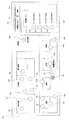
図1は、本発明の実施の形態に係る監視システムの構成を示す図である。
<First Embodiment>
[Configuration and basic operation]
FIG. 1 is a diagram showing a configuration of a monitoring system according to an embodiment of the present invention.
図1を参照して、監視システム101は、複数のセンサ11と、センサ管理装置12と、ディスプレイ13と、基地局14とを備える。
With reference to FIG. 1, the
センサ11は、たとえば、バッテリを含み、当該バッテリから供給される電力によって動作する。センサ11は、たとえば、工場または病院等の監視エリアにおいて設置され、監視対象に関する計測、たとえば監視対象の温度、湿度または電流等の計測を行う。
The
センサ11は、自己のID(Identification)すなわち識別情報と、計測結果を示す計測結果情報とを含むセンサ情報を定期的または不定期に作成し、たとえば無線LAN(Local Area Network)または無線PAN(Personal Area Network)等の通信方式に従って、作成したセンサ情報を基地局14へ無線伝送する。
The
基地局14は、たとえば、監視エリアにおいて設置された無線LANまたは無線PAN等における基地局であり、センサ11から受信したセンサ情報をたとえば有線によりセンサ管理装置12へ送信する。なお、基地局14は、センサ11から受信したセンサ情報を無線によりセンサ管理装置12へ送信する構成であってもよい。
The
センサ管理装置12は、基地局14から各センサ11のセンサ情報を受信し、受信した各センサ情報に基づく内容をディスプレイ13に表示する制御を行う。
The
なお、センサ管理装置12およびディスプレイ13は、監視エリア内に設置されてもよいし、監視エリア外に設置されてもよい。
The
また、監視システム101は、複数の基地局14を備える構成であってもよい。また、センサ管理装置12がディスプレイ13を含む構成であってもよい。
Further, the
図2は、本発明の第1の実施の形態に係る監視システムにおいてディスプレイに表示された画面の一例を示す図である。 FIG. 2 is a diagram showing an example of a screen displayed on the display in the monitoring system according to the first embodiment of the present invention.
図2を参照して、画面は、位置表示エリアDe1と、ボタン表示エリアDe2と、未配置表示エリアDe3とを含む。 Referring to FIG. 2, the screen includes a position display area De1, a button display area De2, and an unplaced display area De3.
位置表示エリアDe1には、監視エリアの地図を示す画像(以下、地図画像とも称する。)が表示されている。 In the position display area De1, an image indicating a map of the monitoring area (hereinafter also referred to as a map image) is displayed.
また、位置表示エリアDe1には、監視エリアに配置された複数のセンサ11にそれぞれ対応するセンサアイコンSe1〜Se12と、監視エリアに配置された複数の基地局14にそれぞれ対応する基地局アイコンAp1〜Ap3と、監視エリアに配置されたセンサ管理装置12に対応する装置アイコンNe1とが表示されている。
In the position display area De1, sensor icons Se1 to Se12 corresponding to the plurality of
具体的には、センサアイコンSe1〜Se12と、基地局アイコンAp1〜Ap3と、装置アイコンNe1とが監視エリアの地図画像上に表示されている。 Specifically, sensor icons Se1 to Se12, base station icons Ap1 to Ap3, and a device icon Ne1 are displayed on the map image of the monitoring area.
センサアイコンSe1〜Se12は、監視エリアにおける対応のセンサ11の位置を示している。つまり、地図画像上のセンサアイコンSe1〜Se12の配置は、監視エリアにおける対応のセンサ11の配置に相当する。
The sensor icons Se1 to Se12 indicate the position of the corresponding
また、基地局アイコンAp1〜Ap3は、監視エリアにおける対応の基地局14の位置を示している。つまり、地図画像上の基地局アイコンAp1〜Ap3の配置は、監視エリアにおける対応の基地局14の配置に相当する。また、装置アイコンNe1は、監視エリアにおけるセンサ管理装置12の位置を示している。
Base station icons Ap1 to Ap3 indicate the positions of the
以下、センサアイコンSe1〜Se12の各々をセンサアイコンSeとも称し、基地局アイコンAp1〜Ap3の各々を基地局アイコンApとも称する。 Hereinafter, each of the sensor icons Se1 to Se12 is also referred to as a sensor icon Se, and each of the base station icons Ap1 to Ap3 is also referred to as a base station icon Ap.
センサ管理装置12は、センサ11の位置を示す位置情報、基地局14の位置を示す位置情報、センサ管理装置12の位置を示す位置情報を記憶している。
The
センサ管理装置12は、記憶しているこれらの位置情報に基づいて、各センサアイコンSe、各基地局アイコンApおよび装置アイコンNe1をそれぞれ地図画像上の対応箇所に表示する。
The
未配置表示エリアDe3には、「未配置リスト」が表示されている。未配置リストには、センサ管理装置12がまた位置情報を取得していないセンサ11の識別情報が表示されている。
An “unplaced list” is displayed in the unplaced display area De3. In the unplaced list, the identification information of the
具体的には、未配置リストには、センサ管理装置12が位置情報を取得していない各センサ11の識別番号と、当該各センサ11に対応するセンサアイコンSn1〜Sn4とが表示されている。以下、センサアイコンSn1〜Sn4の各々をセンサアイコンSnとも称する。
Specifically, in the unplaced list, the identification numbers of the
ユーザは、たとえば、未配置表示エリアDe3に表示されたセンサアイコンSnをマウス等を用いて位置表示エリアDe1へドラッグアンドドロップすることにより、当該センサアイコンSnを地図画像上に配置する。 For example, the user places the sensor icon Sn on the map image by dragging and dropping the sensor icon Sn displayed in the non-placement display area De3 to the position display area De1 using a mouse or the like.
具体的には、ユーザは、未配置表示エリアDe3に表示されたセンサアイコンSnに対応するセンサ11の監視エリアにおける位置を把握したうえで、当該センサアイコンSnを地図画像上の対応の箇所に配置する。
Specifically, the user grasps the position in the monitoring area of the
以下、未配置表示エリアDe3に表示されたセンサアイコンSnを地図画像上の対応箇所に配置する操作をアイコン配置操作とも称する。 Hereinafter, an operation of arranging the sensor icon Sn displayed in the non-placement display area De3 at a corresponding location on the map image is also referred to as an icon placement operation.
センサ管理装置12は、未配置表示エリアDe3に表示されたセンサアイコンSnに対してアイコン配置操作が行われた場合、当該センサアイコンSnの地図画像における配置先の座標を当該センサアイコンSnに対応するセンサ11の位置情報として取得する。
When an icon placement operation is performed on the sensor icon Sn displayed in the unplaced display area De3, the
ユーザのアイコン配置操作によって地図画像上に配置されたセンサアイコンSnは、センサアイコンSeに相当するセンサアイコンになる。 The sensor icon Sn arranged on the map image by the user icon arrangement operation becomes a sensor icon corresponding to the sensor icon Se.
たとえば、ユーザが位置表示エリアDe1におけるセンサアイコンSeをクリックした場合、画面には新たなウィンドウが表示される。当該ウィンドウには、ユーザのクリックしたセンサアイコンSeに対応するセンサ11に関する情報、たとえば、当該センサ11による計測結果が表示される。
For example, when the user clicks the sensor icon Se in the position display area De1, a new window is displayed on the screen. In the window, information on the
ボタン表示エリアDe2には、「地図読み込み」と記載されたボタンBu1と、「更新」と記載されたボタンBu2とが表示されている。 In the button display area De2, a button Bu1 described as “Map reading” and a button Bu2 described as “Update” are displayed.
ユーザは、たとえばセンサ管理装置12の初期設定を行う際、位置表示エリアDe1に監視エリアの地図画像を表示させるために、センサ管理装置12に地図画像を読み込ませる必要がある。
For example, when initial setting of the
センサ管理装置12は、たとえば、ネットワークまたはUSBメモリ経由で地図画像を予め取得しておく。ユーザがボタンBu1をクリックすると、画面には地図画像を選択するためのウィンドウが表示される。ユーザが当該ウィンドウにおいて監視エリアの地図画像を選択すると、センサ管理装置12は、ユーザによって選択された地図画像を読み込み、読み込んだ地図画像を位置表示エリアDe1に表示する。
For example, the
また、ユーザは、未配置表示エリアDe3における未配置リストの内容を更新する場合に、ボタンBu2をクリックする。 Further, the user clicks the button Bu2 when updating the contents of the unplaced list in the unplaced display area De3.
図3は、本発明の第1の実施の形態に係る監視システムにおいてディスプレイに表示された画面の他の例を示す図である。 FIG. 3 is a diagram showing another example of a screen displayed on the display in the monitoring system according to the first embodiment of the present invention.
図3を参照して、センサアイコンSe11は、通常表示における色とは異なる色で表示されている。また、センサアイコンSe11には「異常発生」の文字が付されている。 With reference to FIG. 3, the sensor icon Se11 is displayed in a color different from the color in the normal display. The sensor icon Se11 is marked with “abnormality occurrence”.
センサ管理装置12は、センサ11の計測結果に基づいて、当該センサ11の監視対象において異常が発生したことを検知する。センサ管理装置12は、異常の発生を検知した場合、対応のセンサアイコンSeの表示態様を変更することにより、当該センサ11の監視対象に異常が発生していることをユーザに通知する。
Based on the measurement result of the
図4は、本発明の第1の実施の形態に係るセンサ管理装置の構成の一部を示す図である。 FIG. 4 is a diagram showing a part of the configuration of the sensor management apparatus according to the first embodiment of the present invention.
図4を参照して、センサ管理装置12は、受信処理部21と、記憶部22と、検出部24と、異常検知部25と、表示制御部26と、処理部27と、操作取得部(取得部)28と、操作部29とを備える。
Referring to FIG. 4, the
記憶部22は、センサ管理装置12が画面の表示処理を行うために必要な各種情報を記憶している。
The
具体的には、たとえば、記憶部22は、各センサ11から取得されたセンサ情報の内容を示す計測結果リストKと、各センサ11の位置を示す位置リストPと、各センサ11による計測値の正常範囲を示す正常範囲リストTと、各センサ11の監視対象における異常の有無を示す異常有無リストUと、各基地局14の位置を示す位置情報と、センサ管理装置12の位置を示す位置情報と、監視エリアの地図画像とを記憶している。
Specifically, for example, the
図5は、本発明の第1の実施の形態に係るセンサ管理装置における記憶部が記憶する計測結果リストKの一例を示す図である。 FIG. 5 is a diagram illustrating an example of the measurement result list K stored in the storage unit in the sensor management device according to the first embodiment of the present invention.
図5を参照して、計測結果リストKの一例であるテーブルTA10は、センサ管理装置12が各センサ11から取得したセンサ情報の内容を示している。
With reference to FIG. 5, a table TA10 which is an example of the measurement result list K indicates the content of sensor information acquired from each
具体的には、テーブルTA10は、センサ情報の示すセンサ11の「識別情報」および「計測値」と、センサ管理装置12による当該センサ情報の「取得時刻」とを示している。
Specifically, the table TA10 indicates “identification information” and “measurement value” of the
計測結果リストKは、センサ管理装置12が新たなセンサ情報を取得するたびに更新される。
The measurement result list K is updated each time the
図6は、本発明の第1の実施の形態に係るセンサ管理装置における記憶部が記憶する位置リストPの一例を示す図である。 FIG. 6 is a diagram illustrating an example of the position list P stored in the storage unit in the sensor management device according to the first embodiment of the present invention.
図6を参照して、位置リストPの一例であるテーブルTA20は、センサ11の「識別情報」と当該センサ11の監視エリアにおける位置を示す「位置情報」とを示している。具体的には、たとえば、位置情報は、センサアイコンSeの地図画像における座標を示す。
Referring to FIG. 6, table TA20 which is an example of position list P shows “identification information” of
センサ管理装置12は、上述のように、各センサ11の位置情報をユーザの操作によって取得する。センサ管理装置12が位置情報を未取得であるセンサ11の「位置情報」の欄には「N」が記される。
As described above, the
位置リストPにおける「識別情報」の欄には、たとえば、センサ管理装置12がこれまでに取得したセンサ情報の送信元のセンサ11の識別情報が記される。
In the column of “identification information” in the position list P, for example, the identification information of the
センサ管理装置12が、新たなセンサ11からのセンサ情報を取得した場合、位置リストPにおいて当該センサ11の識別番号が追加される。
When the
たとえば、ユーザがセンサ11を監視エリアにおいて新たに設置した場合であって、センサ管理装置12が当該センサ11からのセンサ情報を取得した場合、位置リストPにおける「識別情報」の欄には当該センサ11の識別番号が追加される。このとき、位置リストPにおける当該センサの「位置情報」の欄には、位置情報が未取得であることを示す「N」が記される。
For example, when the user newly installs the
以下、位置リストPに識別情報が示されていないセンサ11すなわちセンサ管理装置12が位置情報を未取得であるセンサ11を未登録センサとも称する。
Hereinafter, the
センサ管理装置12は、位置リストPにおいて位置情報が登録されているセンサ11については、画面の位置表示エリアDe1に対応のセンサアイコンSeを表示する制御を行う。
The
一方、センサ管理装置12は、位置リストPにおいて位置情報が登録されていない、すなわち「位置情報」の欄に「N」が記されているセンサ11については、画面の未配置表示エリアDe3に対応の識別番号とセンサアイコンSnとを表示する制御を行う。
On the other hand, the
図7は、本発明の第1の実施の形態に係るセンサ管理装置における記憶部が記憶する正常範囲リストTの一例を示す図である。 FIG. 7 is a diagram illustrating an example of a normal range list T stored in the storage unit in the sensor management device according to the first embodiment of the present invention.
図7を参照して、正常範囲リストTの一例であるテーブルTA30は、センサ11の「識別情報」と、当該センサ11による計測値の正常範囲を規定するための「上限値」および「下限値」とを示している。
Referring to FIG. 7, table TA30, which is an example of normal range list T, includes “identification information” of
たとえば、センサ11の計測値が、「下限値」から「上限値」までの範囲に含まれる場合、センサ管理装置12は、センサ11に異常がない、すなわちセンサ11の監視対象において異常が発生していないと判断する。
For example, when the measurement value of the
正常範囲リストTは、たとえば、センサ管理装置12がユーザの操作に基づいて作成したリストである。
The normal range list T is, for example, a list created by the
図8は、本発明の第1の実施の形態に係るセンサ管理装置における記憶部が記憶する異常有無リストUの一例を示す図である。 FIG. 8 is a diagram illustrating an example of the abnormality presence / absence list U stored in the storage unit in the sensor management device according to the first embodiment of the present invention.
図8を参照して、異常有無リストUの一例であるテーブルTA32は、センサ11の「識別情報」と、当該センサ11の監視対象の「状態」とを示している。センサ11の監視対象の状態は、たとえば「正常」および「異常」により表現される。
Referring to FIG. 8, a table TA32 that is an example of the abnormality presence / absence list U indicates “identification information” of the
センサ管理装置12は、図5に示す計測結果リストKおよび図7に示す正常範囲リストTを比較して、センサ11の計測値が正常であるか否か、すなわちセンサ11の監視対象に異常が発生しているか否かを判断し、判断結果を異常有無リストUに反映させる。
The
再び図4を参照して、受信処理部21は、センサ11から基地局14経由でセンサ情報を取得し、取得したセンサ情報に基づいて、記憶部22の記憶する計測結果リストKを更新する。
Referring to FIG. 4 again, the
表示制御部26は、センサの位置を示す位置画面情報をたとえばディスプレイ13に表示する制御を行う。また、表示制御部26は、たとえば、このとき、センサ管理装置12の位置をさらに示す位置画面情報を表示する制御を行う。
The
具体的には、処理部27は、記憶部22の記憶する位置リストP、基地局14の位置情報、センサ管理装置12の位置情報および監視エリアの地図画像に基づいて、たとえば図2における位置表示エリアDe1の表示内容を示す位置画面情報A1を作成する。
Specifically, the
また、処理部27は、たとえば図2におけるボタン表示エリアDe2の表示内容を示すボタン画面情報A2を作成する。また、処理部27は、位置リストPに基づいて、たとえば図2における未配置表示エリアDe3の表示内容を示す未配置画面情報A3を作成する。
Further, the
そして、処理部27は、作成した位置画面情報A1、ボタン画面情報A2および未配置画面情報A3を含む全体画面情報Aaを表示制御部26へ出力する。
Then, the
表示制御部26は、処理部27から受けた全体画面情報Aaをディスプレイ13に送信する。ディスプレイ13には、表示制御部26から受信した全体画面情報Aaの内容が表示される。
The
検出部24は、センサ11を検出する。具体的には、たとえば、検出部24は、記憶部22の記憶する計測結果リストKおよび位置リストPを比較することにより未登録センサを検出する。
The
より具体的には、検出部24は、計測結果リストKに含まれる識別情報の中に、位置リストPに含まれない識別情報が存在する場合に、計測結果リストKに含まれる識別情報であって、かつ位置リストPに含まれない識別情報を未登録センサの識別情報として検出する。
More specifically, the
検出部24は、未登録センサの識別情報を検出した場合、当該識別情報を位置リストPに追加する。位置リストPにおいて、新たに追加された識別情報に対応する「位置情報」の欄には「N」が記される。
When detecting the identification information of the unregistered sensor, the
表示制御部26は、たとえば、検出部24によって検出されたセンサ11の位置が位置情報に含まれない場合に、検出部24によって検出されたセンサ11の識別情報を表示する制御を行う。
For example, when the position of the
具体的には、たとえば、処理部27は、検出部24が未登録センサの識別情報を追加した位置リストPに基づいて、未配置表示エリアDe3の表示内容を示す未配置画面情報B3を作成する。
Specifically, for example, the
また、処理部27は、位置表示エリアDe1の表示内容を示す位置画面情報B1およびボタン表示エリアDe2の表示内容を示すボタン画面情報B2を作成する。
In addition, the
そして、処理部27は、作成した位置画面情報B1、ボタン画面情報B2および未配置画面情報B3を含む全体画面情報Baを表示制御部26へ出力する。
Then, the
表示制御部26は、処理部27から受けた全体画面情報Baをディスプレイ13に送信する。ディスプレイ13には、表示制御部26から受信した全体画面情報Baの内容が表示される。
The
操作部29は、ユーザによるセンサ管理装置12への操作を受け付ける。たとえば、ユーザが、センサ11の位置を指定するための操作を行った場合、操作部29は、当該操作を示す操作情報Aを作成し、作成した操作情報Aを操作取得部28へ出力する。
The
具体的には、たとえば、ユーザが、画面の未配置表示エリアDe3に表示されたセンサアイコンSnに対してアイコン配置操作を行った場合、操作部29は、当該アイコン配置操作の内容を示す操作情報Aを作成し、作成した操作情報Aを操作取得部28へ出力する。操作取得部28は、操作部29からセンサ11の位置を指定するための操作情報Aを取得する。
Specifically, for example, when the user performs an icon placement operation on the sensor icon Sn displayed in the non-placement display area De3 of the screen, the
表示制御部26は、操作取得部28によって取得された操作情報Aに基づいて、センサ11の位置を示す位置画面情報を表示する制御を行う。
The
具体的には、操作取得部28は、操作部29から受けた操作情報Aに基づいて、記憶部22の記憶する位置リストPを更新する。
Specifically, the
たとえば、操作取得部28は、操作部29から受けた操作情報Aの内容を確認し、未配置表示エリアDe3に表示されたセンサアイコンSnに対してユーザがアイコン配置操作を行った際の、地図画像における当該センサアイコンSnの配置先の座標を認識する。
For example, the
そして、操作取得部28は、記憶部22の記憶する位置リストPにおける当該センサアイコンSnに対応する「位置情報」の欄の内容を「N」から当該座標に変更する。
Then, the
処理部27は、記憶部22の記憶する位置リストPに基づいて、位置表示エリアDe1の表示内容を示す位置画面情報C1を作成する。
The
また、処理部27は、ボタン表示エリアDe2の表示内容を示すボタン画面情報C2および未配置表示エリアDe3の表示内容を示す未配置画面情報C3を作成する。
Further, the
そして、処理部27は、作成した位置画面情報C1、ボタン画面情報C2および未配置画面情報C3を含む全体画面情報Caを表示制御部26へ出力する。
Then, the
表示制御部26は、処理部27から受けた全体画面情報Caをディスプレイ13に送信する。ディスプレイ13には、表示制御部26から受信した全体画面情報Caの内容が表示される。
The
異常検知部25は、センサの異常を検知する。具体的には、異常検知部25は、記憶部の記憶する計測結果リストKおよび正常範囲リストTを比較して、センサ11の監視対象における異常を検知する。
The
より具体的には、たとえば、計測結果リストKの示すセンサ11の計測値が正常範囲リストTの示す計測値の正常範囲から外れた場合、当該センサ11の監視対象に異常が発生したと判断する。
More specifically, for example, when the measured value of the
異常検知部25は、センサ11の監視対象に異常が発生したと判断した場合、記憶部22の記憶する異常有無リストUにおける当該センサ11の「状態」の欄の内容を「正常」から「異常」へ変更する。
When the
表示制御部26は、位置画面情報に含まれるセンサ11の位置のうち、異常検知部25によって異常の検知されたセンサ11の位置の表示態様を異常の検知されていないセンサの位置とは異なる表示態様とする。
The
具体的には、たとえば、処理部27は、記憶部22の記憶する異常有無リストUにおいて、位置表示エリアDe1に表示されたセンサアイコンSe11に対応するセンサ11の「状態」の欄の内容が「正常」から「異常」へ変更された場合、図3における位置表示エリアDe1の表示内容を示す位置画面情報D1を作成する。
Specifically, for example, in the abnormality presence / absence list U stored in the
また、処理部27は、ボタン表示エリアDe2の表示内容を示すボタン画面情報D2および未配置表示エリアDe3の表示内容を示す未配置画面情報D3を作成する。
Further, the
そして、処理部27は、作成した位置画面情報D1、ボタン画面情報D2および未配置画面情報D3を含む全体画面情報Daを表示制御部26へ出力する。
Then, the
表示制御部26は、処理部27から受けた全体画面情報Daをディスプレイ13へ送信する。ディスプレイ13には、表示制御部26から受信した全体画面情報Daの内容が表示される。
The
また、受信処理部21は、位置画面情報によって位置が示されているセンサ11のうち、指定されたセンサ11に関する情報を表示する制御を行う。
In addition, the
具体的には、たとえば、ユーザが位置表示エリアDe1に表示されたセンサアイコンSeをクリックした場合、操作部29は、ユーザの操作内容を示す操作情報Bを作成し、作成した操作情報Bを操作取得部28へ出力する。
Specifically, for example, when the user clicks the sensor icon Se displayed in the position display area De1, the
操作取得部28は、操作部29から受けた操作情報Bに基づいて、ユーザによって指定されたセンサアイコンSeを示す指定アイコン情報を作成し、作成した指定アイコン情報を処理部27へ出力する。
The
処理部27は、操作取得部28から指定アイコン情報を受けると、たとえば、記憶部22の記憶する計測結果リストKおよび異常有無リストUを確認する。
When the
そして、処理部27は、指定アイコン情報の示すセンサアイコンSeに対応するセンサ11の計測値および当該センサ11の監視対象の状態を表示するためのウィンドウ画面情報Wを作成し、作成したウィンドウ画面情報Wを含む全体画面情報Waを表示制御部26へ出力する。
Then, the
全体画面情報Waは、位置表示エリアDe1の表示内容を示す位置画面情報、ボタン表示エリアDe2の表示内容を示すボタン画面情報、および未配置表示エリアDe3の表示内容を示す未配置画面情報を含んでもよいし、含まなくてもよい。 The entire screen information Wa may include position screen information indicating the display contents of the position display area De1, button screen information indicating the display contents of the button display area De2, and unplaced screen information indicating the display contents of the unplaced display area De3. It does not have to be included.
表示制御部26は、処理部27から受けた全体画面情報Waをディスプレイ13へ送信する。ディスプレイ13には、たとえば、図2に示す画面に重ねて、ユーザにクリックされたセンサアイコンSeに対応するセンサ11の計測値および当該センサ11の監視対象の状態が表示されたウィンドウが表示される。
The
また、表示制御部26は、所定の操作が行われた場合に識別情報の表示を更新する。具体的には、たとえば、ユーザがボタン表示エリアDe2における「更新」と記載されたボタンBu2をクリックした場合、操作部29は、ユーザの操作内容を示す操作情報Cを作成して、作成した操作情報Cを操作取得部28へ出力する。
Further, the
操作取得部28は、操作部29から受けた操作情報Cに基づいて、未配置表示エリアDe3における未配置リストの更新を指示するための更新指示情報を作成し、作成した更新指示情報を処理部27へ出力する。
Based on the operation information C received from the
処理部27は、操作取得部28から更新指示情報を受けると、記憶部22に記憶された位置リストPを確認し、位置リストPに基づいて、未配置表示エリアDe3の表示内容を示す未配置画面情報E3を作成し、作成した未配置画面情報E3を含む全体画面情報Eaを表示制御部26へ出力する。
When the
表示制御部26は、処理部27から受けた全体画面情報Eaをディスプレイ13へ送信する。ディスプレイ13には、表示制御部26から受信した全体画面情報Eaの内容が表示される。
The
[動作]
次に、本発明の第1の実施の形態に係る監視システムが画面表示処理を行う際の動作について説明する。
[Operation]
Next, the operation when the monitoring system according to the first embodiment of the present invention performs screen display processing will be described.
監視システム101における各装置は、コンピュータを備え、当該コンピュータにおけるCPU等の演算処理部は、以下のフローチャートおよびシーケンスの各ステップの一部または全部を含むプログラムを図示しないメモリから読み出して実行する。これら複数の装置のプログラムは、それぞれ、外部からインストールすることができる。これら複数の装置のプログラムは、それぞれ、記録媒体に格納された状態で流通する。
Each device in the
図9は、本発明の第1の実施の形態に係る監視システムにおける画面表示処理のシーケンスの一例を示す図である。 FIG. 9 is a diagram showing an example of a sequence of screen display processing in the monitoring system according to the first embodiment of the present invention.
図9を参照して、まず、センサ11Aは、定期的または不定期に、センサ情報をセンサ管理装置12へ送信する(ステップS11)。センサ11Aは、たとえば、図2における位置表示エリアDe1に表示されたセンサアイコンSe11に対応するセンサ11である。
With reference to FIG. 9, first, the
次に、センサ管理装置12は、センサ11Aからセンサ情報を受信する。センサ管理装置12は、センサ11Aの位置を示す位置画面情報をたとえばディスプレイ13に表示する制御を行う。具体的には、たとえば、センサ管理装置12は、上記の全体画面情報Aaをディスプレイ13へ送信する(ステップS12)。ディスプレイ13には、全体画面情報Aaの内容が表示される。
Next, the
ここで、センサ11Bがたとえば初めてセンサ情報をセンサ管理装置12へ送信する(ステップS13)。
Here, for example, the sensor 11B transmits sensor information to the
次に、センサ管理装置12は、センサ11Bを未登録センサとして検出し(ステップS14)、検出したセンサ11Bの識別情報を表示する制御を行う。具体的には、たとえば、センサ管理装置12は、上記の全体画面情報Baをディスプレイ13へ送信する(ステップS15)。ディスプレイ13には、全体画面情報Baの内容が表示される。
Next, the
次に、たとえば、ユーザが、センサ11の位置を指定するための操作、具体的には、未配置表示エリアDe3に表示されたセンサアイコンSnに対してアイコン配置操作を行った場合、センサ管理装置12は、当該操作の内容を受け付ける(ステップS16)。
Next, for example, when the user performs an operation for designating the position of the
次に、センサ管理装置12は、受け付けた上記操作の内容に基づいて、当該センサ11の位置を示す位置画面情報を表示する制御を行う。具体的には、たとえば、センサ管理装置12は、上記の全体画面情報Caをディスプレイ13へ送信する(ステップS17)。ディスプレイ13には、全体画面情報Caの内容が表示される。
Next, the
図10は、本発明の第1の実施の形態に係るセンサ管理装置による画面表示処理の手順の一例を定めたフローチャートである。 FIG. 10 is a flowchart that defines an example of the procedure of screen display processing by the sensor management apparatus according to the first embodiment of the present invention.
図10を参照して、まず、センサ管理装置12は、センサの異常を検知する。具体的には、センサ管理装置12は、位置表示エリアDe1に表示された各センサアイコンSeに対応するセンサ11の監視対象において、異常が発生しているか否かを判断する(ステップS30)。
Referring to FIG. 10, first, the
次に、センサ管理装置12は、センサ11の監視対象において異常が発生していると判断した場合、つまりセンサ11の異常を検知した場合(ステップS30でYES)、位置表示エリアDe1に表示された当該センサ11の位置の表示態様すなわち当該センサ11に対応するセンサアイコンSeの表示態様を変更する(ステップS31)。
Next, when the
具体的には、たとえば、センサ管理装置12は、上記の全体画面情報Daをディスプレイ13へ送信する。
Specifically, for example, the
次に、センサ管理装置12は、ユーザによってセンサ11が指定されたか否かを確認する(ステップS32)。具体的には、センサ管理装置12は、位置表示エリアDe1においてセンサアイコンSeがユーザによってクリックされたか否かを確認する。
Next, the
次に、センサ管理装置12は、センサ11が指定されたことを確認した場合、(ステップS32でYES)、当該センサ11に関する情報を表示する制御を行う(ステップS33)。具体的には、たとえば、センサ管理装置12は、上記の全体画面情報Waをディスプレイ13へ送信する。
Next, when it is confirmed that the
一方、センサ管理装置12は、センサの異常を検知しなかった場合(ステップS30でNO)、センサアイコンSeの表示態様を変更する制御を行わずに、ユーザによってセンサ11が指定されたか否かを確認する(ステップS32)。
On the other hand, if no sensor abnormality is detected (NO in step S30), the
また、センサ管理装置12は、ユーザによってセンサ11が指定されていなかった場合(ステップS32でNO)、センサ11に関する情報を表示する制御を行わずに、センサ11の監視対象における異常の有無を再び判断する(ステップS30)。
In addition, when the
なお、本発明の第1の実施の形態に係る監視システム101では、センサ管理装置12における表示制御部26は、検出部24によって検出されたセンサ11の識別情報を示す未配置画面情報およびセンサ11の位置を示す位置画面情報をディスプレイ13に表示する制御を行う構成であるとしたが、これに限定するものではない。
Note that, in the
具体的には、たとえば、センサ管理装置12は、ネットワークを介して端末装置と接続される。センサ管理装置12における表示制御部26は、位置画面情報、ボタン画面情報および未配置画面情報を含む全体画面情報を当該端末装置へ送信する。当該端末装置は、センサ管理装置12から受信した全体画面情報を自己のディスプレイに表示する。
Specifically, for example, the
また、本発明の第1の実施の形態に係る監視システム101では、センサ管理装置12は、自己が位置情報を取得していないセンサ11の識別情報および当該センサ11に対応するセンサアイコンを画面の未配置表示エリアDe3に表示する制御を行う構成であるとしたが、これに限定するものではない。
In the
たとえば、センサ管理装置12は、自己が位置情報を取得していない基地局14の識別情報および当該基地局14に対応するアイコンを画面の未配置表示エリアDe3に表示する制御を行う構成であってもよい。
For example, the
また、本発明の第1の実施の形態に係る監視システム101では、未配置表示エリアDe3に表示されたセンサアイコンは、ユーザのドラッグアンドドロップによって地図画像上に配置される構成であるとしたが、これに限定するものではない。
In the
たとえば、センサ管理装置12は、ユーザから地図画像における座標の入力を受けて、対象のセンサアイコンを地図画像における当該座標の示す箇所に配置する構成であってもよい。
For example, the
この場合、センサ管理装置12は、ユーザが入力した座標を対応のセンサ11の位置情報として取得する。具体的には、センサ管理装置12における操作部29は、ユーザが入力した座標を示す操作情報を操作取得部28へ出力する。操作取得部28は、操作部29から操作情報を受ける。表示制御部26は、操作取得部28によって取得された当該操作情報に基づいて、センサ11の位置を示す位置画面情報を表示する制御を行う。
In this case, the
ところで、特許文献1に記載された技術を用いて所定エリアにおける各センサの位置を画面に表示している状況において、各センサの中に位置の不明なセンサがある場合、画面には当該センサの位置が表示されない。このような場合、当該センサの計測値に異常が有ることをユーザが認識しても、当該センサの設置場所へ移動することは困難である。 By the way, in the situation where the position of each sensor in a predetermined area is displayed on the screen using the technique described in Patent Document 1, if there is a sensor whose position is unknown among the sensors, the screen displays the sensor's position. The position is not displayed. In such a case, even if the user recognizes that there is an abnormality in the measured value of the sensor, it is difficult to move to the installation location of the sensor.
これに対して、本発明の第1の実施の形態に係るセンサ管理装置では、表示制御部26は、センサ11の位置を示す位置画面情報を表示する制御を行う。検出部24は、センサ11を検出する。表示制御部26は、検出部24によって検出されたセンサ11の位置が位置画面情報に含まれていない場合に、検出部24によって検出されたセンサ11の識別情報を表示する制御をさらに行う。
On the other hand, in the sensor management apparatus according to the first embodiment of the present invention, the
このように、センサ管理装置12において位置を把握していないセンサ11を検出した場合に、当該センサ11の識別情報を画面に表示する構成により、ユーザは、位置が把握されていないセンサ11の存在を画面において認識することができるため、たとえば、当該センサ11の位置を把握するために必要な措置をとることができる。
As described above, when the
また、センサ11の位置を画面に表示することにより、たとえば、センサ11を設置したユーザ以外のユーザもセンサ11の位置を正しく認識することができる。
Further, by displaying the position of the
したがって、本発明の第1の実施の形態に係るセンサ管理装置では、センサの位置を適切に管理することができる。 Therefore, the sensor management apparatus according to the first embodiment of the present invention can appropriately manage the position of the sensor.
また、本発明の第1の実施の形態に係るセンサ管理装置では、操作取得部(取得部)28は、センサ11の位置を指定するための操作を示す操作情報を取得する。表示制御部26は、操作取得部28によって取得された操作情報に基づいて、位置画面情報を表示する制御を行う。
In the sensor management device according to the first embodiment of the present invention, the operation acquisition unit (acquisition unit) 28 acquires operation information indicating an operation for specifying the position of the
このような構成により、センサ管理装置12がセンサ11の位置を認識し、認識したセンサ11の位置を画面に表示することができる。たとえば、センサ管理装置12において位置を把握していないセンサ11の位置を画面に追加することができる。
With this configuration, the
また、本発明の第1の実施の形態に係るセンサ管理装置では、異常検知部25は、センサ11の異常を検知する。表示制御部26は、位置画面情報に含まれる位置のうち、異常検知部25によって異常の検知されたセンサ11の位置の表示態様を異常の検知されていないセンサ11の位置とは異なる表示態様とする。
In the sensor management device according to the first embodiment of the present invention, the
このような構成により、センサ11の計測結果に異常がある場合に、ユーザが当該センサ11の位置を容易に認識することができる。これにより、ユーザは、当該センサ11の設置場所へ速やかに移動し、当該センサ11による監視対象の状態を直接確認することができる。
With such a configuration, when the measurement result of the
また、本発明の第1の実施の形態に係るセンサ管理装置では、表示制御部26は、位置画面情報によって位置が示されているセンサ11のうち、指定されたセンサ11に関する情報を表示する制御をさらに行う。
Further, in the sensor management device according to the first embodiment of the present invention, the
このような構成により、ユーザは、所望するセンサ11の計測結果等を容易に確認することができる。
With such a configuration, the user can easily confirm a desired measurement result of the
また、本発明の第1の実施の形態に係るセンサ管理装置では、表示制御部26は、センサ管理装置12の位置をさらに示す位置画面情報を表示する制御を行う。
In the sensor management device according to the first embodiment of the present invention, the
このような構成により、たとえば、ユーザは、センサ管理装置12の近くにいる場合において、画面に表示されたセンサ11とセンサ管理装置12との位置関係を確認することにより、センサ11の位置をより容易に認識することができる。
With such a configuration, for example, when the user is in the vicinity of the
また、本発明の第1の実施の形態に係るセンサ管理装置では、表示制御部26は、所定の操作が行われた場合に識別情報の表示を更新する。
Further, in the sensor management device according to the first embodiment of the present invention, the
このような構成により、たとえば、センサ管理装置12による識別情報の表示の更新頻度を下げることができるため、センサ管理装置12の処理負荷を減らすことができる。
With such a configuration, for example, the update frequency of the display of the identification information by the
次に、本発明の他の実施の形態について図面を用いて説明する。なお、図中同一または相当部分には同一符号を付してその説明は繰り返さない。 Next, another embodiment of the present invention will be described with reference to the drawings. In the drawings, the same or corresponding parts are denoted by the same reference numerals and description thereof will not be repeated.
<第2の実施の形態>
本実施の形態は、第1の実施の形態に係る監視システムと比べて、センサの移動を検知する監視システムに関する。以下で説明する内容以外は、第1の実施の形態に係る監視システムと同様である。
<Second Embodiment>
The present embodiment relates to a monitoring system that detects the movement of a sensor as compared to the monitoring system according to the first embodiment. The contents other than those described below are the same as those of the monitoring system according to the first embodiment.
[構成および基本動作]
図11は、本発明の第2の実施の形態に係る監視システムの構成を示す図である。
[Configuration and basic operation]
FIG. 11 is a diagram showing a configuration of a monitoring system according to the second embodiment of the present invention.
図11を参照して、監視システム102は、複数のセンサ11と、基地局14A,14B,14Cと、センサ管理装置12と、ディスプレイ13とを備える。以下、基地局14A,14B,14Cの各々を基地局14とも称する。
Referring to FIG. 11, the
センサ11は、たとえば、工場または病院等の監視エリアにおいて設置され、監視対象に関する計測、たとえば監視対象の温度、湿度または電流等の計測を行う。
The
センサ11は、自己の識別情報と、計測結果を示す計測結果情報とを含むセンサ情報を作成し、作成したセンサ情報を無線により基地局14A,14B,14Cへ送信する。
The
基地局14は、センサ11からセンサ情報を受信すると、当該センサ情報を受信した際の当該センサ11からの電波の強度を示す電波強度情報を当該センサ情報に付加する。そして、基地局14は、電波強度情報を付加したセンサ情報をたとえば有線によりセンサ管理装置12へ送信する。
When the
監視エリアに配置されたセンサ11がユーザによって移動された場合、センサ管理装置12は、たとえば、各基地局14から受信したセンサ情報に基づいて、センサ11の移動を検知し、さらに移動先を推測する。そして、センサ管理装置12は、推測したセンサ11の移動先を画面に表示する制御を行う。
When the
図12は、本発明の第2の実施の形態に係る監視システムにおいてディスプレイに表示された画面の一例を示す図である。 FIG. 12 is a diagram illustrating an example of a screen displayed on the display in the monitoring system according to the second embodiment of the present invention.
図12は、センサ管理装置12がセンサ11の移動を検知した場合においてディスプレイ13に表示された画面を示している。
FIG. 12 shows a screen displayed on the
図12を参照して、位置表示エリアDe1において、移動の検知されたセンサ11に対応するセンサアイコンSeであるセンサアイコンSe11に「移動発生」の文字が付されている。また、位置表示エリアDe1において、センサ管理装置12が推測した当該センサ11の移動先を示すセンサアイコンPrが表示されている。また、位置表示エリアDe1において、センサアイコンSe11からセンサアイコンPrへ伸びる矢印Arが表示されている。
Referring to FIG. 12, in the position display area De <b> 1, the word “movement occurrence” is attached to the sensor icon Se <b> 11 that is the sensor icon Se corresponding to the
センサ管理装置12は、このような表示を行うことにより、センサ11が移動されたこと、および当該センサ11のおおよその移動先をユーザに通知する。
By performing such display, the
図13は、本発明の第2の実施の形態に係るセンサ管理装置の構成の一部を示す図である。 FIG. 13 is a diagram illustrating a part of the configuration of the sensor management apparatus according to the second embodiment of the present invention.
図13を参照して、センサ管理装置12は、受信処理部21と、記憶部22と、移動検知部23と、検出部24と、異常検知部25と、表示制御部26と、処理部27と、操作取得部(取得部)28と、操作部29とを備える。
Referring to FIG. 13, the
すなわち、センサ管理装置12は、図4に示すセンサ管理装置12と比べて、さらに、移動検知部23を備える。また、センサ管理装置12における受信処理部21と、記憶部22と、検出部24と、表示制御部26と、処理部27とは、第1の実施の形態において説明した動作に加え、さらに以下に説明する動作を行う。
That is, the
記憶部22は、センサ管理装置12が画面の表示処理を行うために必要な各種情報を記憶している。
The
具体的には、記憶部22は、たとえば、計測結果リストKと、位置リストPと、正常範囲リストTと、異常有無リストUと、各基地局14の位置を示す位置情報と、センサ管理装置12の位置を示す位置情報と、センサ情報に基づいて作成された電波強度リストMおよび平均強度リストMaとを記憶している。
Specifically, the
図14は、本発明の第2の実施の形態に係るセンサ管理装置における記憶部が記憶する電波強度リストMの一例を示す図である。 FIG. 14 is a diagram illustrating an example of the radio wave intensity list M stored in the storage unit in the sensor management device according to the second embodiment of the present invention.
図14を参照して、電波強度リストMの一例であるテーブルTA60は、センサ管理装置12が取得したセンサ情報に付加された電波強度情報を示している。
Referring to FIG. 14, a table TA60 that is an example of the radio wave intensity list M indicates radio wave intensity information added to the sensor information acquired by the
具体的には、テーブルTA60は、センサ情報の送信元のセンサ11を示す「識別情報」と、当該センサ情報が経由した基地局14の別と、当該基地局14において当該センサ情報に付加された電波強度情報の内容である「電波強度」と、センサ管理装置12による当該センサ情報の「取得時刻」とを示している。
Specifically, the table TA60 is added to the sensor information in the
電波強度リストMは、センサ管理装置12が新たなセンサ情報を基地局14から取得するたびに更新される。
The radio wave intensity list M is updated each time the
図15は、本発明の第2の実施の形態に係るセンサ管理装置における記憶部が記憶する平均強度リストMaの一例を示す図である。 FIG. 15 is a diagram illustrating an example of the average intensity list Ma stored in the storage unit in the sensor management device according to the second embodiment of the present invention.
図15を参照して、平均強度リストMaの一例であるテーブルTA62は、センサ11の「識別情報」と、当該センサ11から出力された電波の各基地局14における強度の平均値とを示している。
Referring to FIG. 15, a table TA62 which is an example of the average intensity list Ma shows “identification information” of the
センサ管理装置12は、図14に示す電波強度リストMに基づいて、平均強度リストMaを作成する。
The
再び図13を参照して、受信処理部21は、基地局14経由でセンサ11からのセンサ情報を取得し、取得したセンサ情報に基づいて、記憶部22の記憶する電波強度リストMを更新する。
Referring to FIG. 13 again, the
移動検知部23は、電波強度リストMに基づいて、平均強度リストMaを更新する。また、移動検知部23は、センサ11の移動を検知する。具体的には。移動検知部23は、たとえばユーザによって、監視エリアにおけるセンサ11が移動された場合に、当該センサ11が移動されたことを検知する。
The
より具体的には、たとえば、移動検知部23は、記憶部22の記憶する電波強度リストMおよび平均強度リストMaを比較して、センサ11から出力された電波の各基地局14における強度が、当該強度の平均値と比べて所定値以上乖離している場合、当該センサ11が移動されたと判断する。
More specifically, for example, the
移動検知部23は、センサ11が移動されたと判断した場合、たとえば、電波強度リストMに基づいて、当該センサ11の移動先を推測する。
When the
移動検知部23は、当該センサ11の推測した移動先を示す移動先情報を作成し、作成した移動先情報を記憶部22に保存する。
The
表示制御部26は、位置画面情報に含まれるセンサ11の位置のうち、移動検知部23によって移動の検知されたセンサの位置の表示態様を移動の検知されていないセンサ11の位置とは異なる表示態様とする。
The
具体的には、表示制御部26は、位置表示エリアDe1に表示されたセンサアイコンSeのうち、移動検知部23によって移動の検知されたセンサ11のセンサアイコンSeの表示態様を、移動の検知されていないセンサ11のセンサアイコンSeとは異なる表示態様で表示する制御を行う。
Specifically, the
また、このとき、表示制御部26は、たとえば、移動の検知されたセンサ11の移動元および移動先を示す位置画面情報を表示する制御を行う。
At this time, for example, the
具体的には、たとえば、処理部27は、位置表示エリアDe1に表示されたセンサアイコンSe11に対応するセンサ11の移動先情報が記憶部22に保存されると、当該移動先情報に基づいて、図12における位置表示エリアDe1の表示内容を示す位置画面情報F1を作成する。
Specifically, for example, when the movement destination information of the
また、処理部27は、たとえば、図12におけるボタン表示エリアDe2の表示内容を示すボタン画面情報F2、および図12における未配置表示エリアDe3の表示内容を示す未配置画面情報F3を作成する。
Further, the
そして、処理部27は、作成した位置画面情報F1、ボタン画面情報F2および未配置画面情報F3を含む全体画面情報Faを表示制御部26へ出力する。
Then, the
表示制御部26は、たとえば、処理部27から受けた全体画面情報Faをディスプレイ13へ送信する。ディスプレイ13には、表示制御部26から受信した全体画面情報Faの内容が表示される。
For example, the
[動作]
次に、本発明の第2の実施の形態に係る監視システムが画面表示処理を行う際の動作について説明する。
[Operation]
Next, an operation when the monitoring system according to the second embodiment of the present invention performs screen display processing will be described.
監視システム102における各装置は、コンピュータを備え、当該コンピュータにおけるCPU等の演算処理部は、以下のフローチャートおよびシーケンスの各ステップの一部または全部を含むプログラムを図示しないメモリから読み出して実行する。これら複数の装置のプログラムは、それぞれ、外部からインストールすることができる。これら複数の装置のプログラムは、それぞれ、記録媒体に格納された状態で流通する。
Each device in the
図16は、本発明の第2の実施の形態に係るセンサ管理装置による画面表示処理の手順の一例を定めたフローチャートである。 FIG. 16 is a flowchart defining an example of the procedure of screen display processing by the sensor management device according to the second embodiment of the present invention.
図16を参照して、まず、センサ管理装置12は、センサの異常を検知する。具体的には、センサ管理装置12は、位置表示エリアDe1に表示された各センサアイコンSeに対応するセンサ11の監視対象において、異常が発生しているか否かを判断する(ステップS130)。
With reference to FIG. 16, first, the
次に、センサ管理装置12は、当該センサ11の監視対象において異常が発生していると判断した場合、つまり当該センサ11の異常を検知した場合(ステップS130でYES)、位置表示エリアDe1に表示された当該センサ11の位置の表示態様すなわち当該センサ11に対応するセンサアイコンSeの表示態様を変更する(ステップS131)。
Next, when the
具体的には、たとえば、センサ管理装置12は、上記の全体画面情報Daをディスプレイ13へ送信する。
Specifically, for example, the
次に、センサ管理装置12は、ユーザによってセンサ11が指定されたか否かを確認する(ステップS132)。具体的には、センサ管理装置12は、位置表示エリアDe1においてセンサアイコンSeがユーザによってクリックされたか否かを確認する。
Next, the
次に、センサ管理装置12は、センサ11が指定されたことを確認した場合、(ステップS132でYES)、当該センサ11に関する情報を表示する制御を行う(ステップS133)。具体的には、センサ管理装置12は、上記の全体画面情報Waをディスプレイ13へ送信する。
Next, when the
次に、センサ管理装置12は、センサ11が移動されたか否かを判断する(ステップS134)。
Next, the
次に、センサ管理装置12は、センサ11が移動されたと判断した場合すなわちセンサ11の移動を検知した場合(ステップS134でYES)、当該センサ11に対応するセンサアイコンSeの表示態様を変更する(ステップS135)。また、その際、センサ管理装置12は、画面において、センサ11の移動先を示す。
Next, when it is determined that the
具体的には、センサ管理装置12は、たとえば上記の全体画面情報Faをディスプレイ13へ送信する。
Specifically, for example, the
一方、センサ管理装置12は、センサの異常を検知しなかった場合(ステップS130でNO)、センサアイコンSeの表示態様を変更する制御を行わずに、ユーザによってセンサ11が指定されたか否かを確認する(ステップS132)。
On the other hand, if no sensor abnormality is detected (NO in step S130), the
また、センサ管理装置12は、ユーザによってセンサ11が指定されていなかった場合(ステップS132でNO)、センサ11に関する情報を表示する制御を行わずに、センサ11が移動されたか否かを判断する(ステップS134)。
Further, when the
また、センサ管理装置12は、センサ11が移動されていないと判断した場合(ステップS134でNO)、センサアイコンSeの表示態様を変更せずに、再びセンサ11の監視対象における異常の有無を判断する(ステップS130)。
If the
なお、本発明の第2の実施の形態に係るセンサ管理装置12は、センサ11から出力された電波の各基地局14における強度に基づいて、センサ11の移動を検知する構成であるとしたが、これに限定するものではない。
The
たとえば、センサ管理装置12は、センサ11が送信した同じセンサ情報の各基地局14における受信時刻の差に基づいて、センサ11の移動を検知する構成であってもよいし、センサ11がセンサ情報を送信してから基地局14によって受信されるまでに要した時間から算出したセンサ11と各基地局14との距離に基づいて、センサ11の移動を検知する構成であってもよい。
For example, the
以上のように、本発明の第2の実施の形態に係るセンサ管理装置では、移動検知部23は、センサ11の移動を検知する。表示制御部26は、位置画面情報に含まれる位置のうち、移動検知部23によって移動の検知されたセンサ11の位置の表示態様を移動の検知されていないセンサ11の位置とは異なる表示態様とする。
As described above, in the sensor management device according to the second embodiment of the present invention, the
このような構成により、たとえば、あるユーザがセンサ11を移動した場合に、当該センサ11が移動されたことを他のユーザが容易に認識することができる。
With such a configuration, for example, when a certain user moves the
また、本発明の第2の実施の形態に係るセンサ管理装置では、表示制御部26は、センサ11の移動元および移動先をさらに示す位置画面情報を表示する制御を行う。
In the sensor management device according to the second embodiment of the present invention, the
このような構成により、センサ11の詳細な移動内容をユーザが認識することができる。
With such a configuration, the user can recognize the detailed movement contents of the
その他の構成および動作は第1の実施の形態に係る監視システムと同様であるため、ここでは詳細な説明を繰り返さない。 Since other configurations and operations are the same as those of the monitoring system according to the first embodiment, detailed description thereof will not be repeated here.
上記実施の形態は、すべての点で例示であって制限的なものではないと考えられるべきである。本発明の範囲は、上記説明ではなく特許請求の範囲によって示され、特許請求の範囲と均等の意味および範囲内でのすべての変更が含まれることが意図される。 The above embodiment should be considered as illustrative in all points and not restrictive. The scope of the present invention is defined by the terms of the claims, rather than the description above, and is intended to include any modifications within the scope and meaning equivalent to the terms of the claims.
以上の説明は、以下に付記する特徴を含む。 The above description includes the following features.
[付記]
センサの位置を示す位置画面情報を表示する制御を行う表示制御部と、
センサを検出する検出部とを備え、
前記表示制御部は、前記検出部によって検出されたセンサの位置が前記位置画面情報に含まれていない場合に、前記検出部によって検出された前記センサの識別情報を表示する制御をさらに行い、
前記表示制御部は、前記位置画面情報として、前記センサの配置された所定エリアの地図を示す画像とともに前記所定エリアにおける前記センサの位置を示すアイコンを表示する制御を行い、
さらに、
前記センサから送信された前記センサの識別情報を含むセンサ情報を取得する受信処理部を備え、
前記検出部は、前記受信処理部によって取得された前記センサ情報に基づいて、前記センサを検出する、センサ管理装置。
[Appendix]
A display control unit that performs control to display position screen information indicating the position of the sensor;
A detection unit for detecting the sensor,
The display control unit further performs control to display the identification information of the sensor detected by the detection unit when the position of the sensor detected by the detection unit is not included in the position screen information,
The display control unit performs control to display an icon indicating a position of the sensor in the predetermined area together with an image indicating a map of the predetermined area where the sensor is arranged as the position screen information,
further,
A reception processing unit that acquires sensor information including identification information of the sensor transmitted from the sensor;
The detection unit is a sensor management device that detects the sensor based on the sensor information acquired by the reception processing unit.
11,11A,11B センサ
12 センサ管理装置
13 ディスプレイ
14,14A,14B,14C 基地局
21 受信処理部
22 記憶部
23 移動検知部
24 検出部
25 異常検知部
26 表示制御部
27 処理部
28 操作取得部
29 操作部
101,102 監視システム
11, 11A,
Claims (10)
センサを検出する検出部とを備え、
前記表示制御部は、前記検出部によって検出されたセンサの位置が前記位置画面情報に含まれていない場合に、前記検出部によって検出された前記センサの識別情報を表示する制御をさらに行う、センサ管理装置。 A display control unit that performs control to display position screen information indicating the position of the sensor;
A detection unit for detecting the sensor,
The display control unit further performs control to display identification information of the sensor detected by the detection unit when a position of the sensor detected by the detection unit is not included in the position screen information. Management device.
センサの位置を指定するための操作を示す操作情報を取得する取得部を備え、
前記表示制御部は、前記取得部によって取得された前記操作情報に基づいて、前記位置画面情報を表示する制御を行う、請求項1に記載のセンサ管理装置。 The sensor management device further includes:
An acquisition unit that acquires operation information indicating an operation for specifying the position of the sensor;
The sensor management apparatus according to claim 1, wherein the display control unit performs control to display the position screen information based on the operation information acquired by the acquisition unit.
センサの異常を検知する異常検知部を備え、
前記表示制御部は、前記位置画面情報に含まれる前記位置のうち、前記異常検知部によって異常の検知されたセンサの位置の表示態様を異常の検知されていないセンサの位置とは異なる表示態様とする、請求項1または請求項2に記載のセンサ管理装置。 The sensor management device further includes:
It has an abnormality detection unit that detects sensor abnormalities,
The display control unit includes a display mode that is different from a position of a sensor in which an abnormality is not detected, among the positions included in the position screen information. The sensor management device according to claim 1 or 2.
センサの移動を検知する移動検知部を備え、
前記表示制御部は、前記位置画面情報に含まれる前記位置のうち、前記移動検知部によって移動の検知されたセンサの位置の表示態様を移動の検知されていないセンサの位置とは異なる表示態様とする、請求項1から請求項3のいずれか1項に記載のセンサ管理装置。 The sensor management device further includes:
A movement detection unit that detects the movement of the sensor
The display control unit is configured to display a display mode of the position of the sensor whose movement is detected by the movement detection unit out of the positions included in the position screen information, and a display mode different from the position of the sensor whose movement is not detected. The sensor management device according to any one of claims 1 to 3.
センサの位置を示す位置画面情報を表示する制御を行うステップと、
センサを検出するステップと、
検出したセンサの位置が前記位置画面情報に含まれていない場合に、検出した前記センサの識別情報を表示する制御を行うステップとを含む、センサ管理方法。 A sensor management method in a sensor management device,
Performing control to display position screen information indicating the position of the sensor;
Detecting a sensor;
Performing a control to display identification information of the detected sensor when the position of the detected sensor is not included in the position screen information.
センサの位置を示す位置画面情報を表示する制御を行うステップと、
センサを検出するステップと、
検出したセンサの位置が前記位置画面情報に含まれていない場合に、検出した前記センサの識別情報を表示する制御を行うステップとを実行させるための、センサ管理プログラム。 A sensor management program used in a sensor management device, which is
Performing control to display position screen information indicating the position of the sensor;
Detecting a sensor;
A sensor management program for executing a control of displaying identification information of the detected sensor when the position of the detected sensor is not included in the position screen information.
Priority Applications (3)
| Application Number | Priority Date | Filing Date | Title |
|---|---|---|---|
| JP2015101636A JP6197827B2 (en) | 2015-05-19 | 2015-05-19 | Sensor management apparatus, sensor management method, and sensor management program |
| PCT/JP2016/051982 WO2016185731A1 (en) | 2015-05-19 | 2016-01-25 | Sensor management device, sensor management method and sensor management program |
| US15/574,375 US10019890B2 (en) | 2015-05-19 | 2016-01-25 | Sensor management device, sensor management method, and sensor management program |
Applications Claiming Priority (1)
| Application Number | Priority Date | Filing Date | Title |
|---|---|---|---|
| JP2015101636A JP6197827B2 (en) | 2015-05-19 | 2015-05-19 | Sensor management apparatus, sensor management method, and sensor management program |
Publications (3)
| Publication Number | Publication Date |
|---|---|
| JP2016218659A true JP2016218659A (en) | 2016-12-22 |
| JP2016218659A5 JP2016218659A5 (en) | 2017-06-29 |
| JP6197827B2 JP6197827B2 (en) | 2017-09-20 |
Family
ID=57319708
Family Applications (1)
| Application Number | Title | Priority Date | Filing Date |
|---|---|---|---|
| JP2015101636A Active JP6197827B2 (en) | 2015-05-19 | 2015-05-19 | Sensor management apparatus, sensor management method, and sensor management program |
Country Status (3)
| Country | Link |
|---|---|
| US (1) | US10019890B2 (en) |
| JP (1) | JP6197827B2 (en) |
| WO (1) | WO2016185731A1 (en) |
Cited By (3)
| Publication number | Priority date | Publication date | Assignee | Title |
|---|---|---|---|---|
| JP2020154718A (en) * | 2019-03-20 | 2020-09-24 | 株式会社日立製作所 | Action detection system, interface device, and robot |
| JP2020156156A (en) * | 2019-03-18 | 2020-09-24 | 株式会社Gsユアサ | Information processing device, information processing system, information processing method, and computer program |
| JP2021050993A (en) * | 2019-09-25 | 2021-04-01 | 株式会社日立国際電気 | Management device of installation of sensor terminal |
Families Citing this family (3)
| Publication number | Priority date | Publication date | Assignee | Title |
|---|---|---|---|---|
| US10088389B2 (en) | 2013-03-15 | 2018-10-02 | Fluke Corporation | Automatic recording and graphing of measurement data |
| JP6485428B2 (en) * | 2016-10-06 | 2019-03-20 | 住友電気工業株式会社 | Management system, management apparatus, management method, and management program |
| US11626010B2 (en) * | 2019-02-28 | 2023-04-11 | Nortek Security & Control Llc | Dynamic partition of a security system |
Citations (7)
| Publication number | Priority date | Publication date | Assignee | Title |
|---|---|---|---|---|
| JP2004326623A (en) * | 2003-04-25 | 2004-11-18 | Navi Community Kk | Internet remote monitoring method for safety, and program |
| JP2006285636A (en) * | 2005-03-31 | 2006-10-19 | Fujitsu Ltd | Position management system |
| JP2007108884A (en) * | 2005-10-11 | 2007-04-26 | Actment Co Ltd | Wireless sensor and wireless monitoring system using the same |
| JP2010524094A (en) * | 2007-04-04 | 2010-07-15 | マグネットー・イナーシャル・センシング・テクノロジー・インコーポレイテッド | Dynamically configurable wireless sensor network |
| JP2010231659A (en) * | 2009-03-27 | 2010-10-14 | Sogo Keibi Hosho Co Ltd | System, terminal, method, and program for inspecting security |
| JP2010231660A (en) * | 2009-03-27 | 2010-10-14 | Sogo Keibi Hosho Co Ltd | Inspection state management system, inspection state management device, inspection state management method and inspection state management program |
| JP2010272065A (en) * | 2009-05-25 | 2010-12-02 | Sony Corp | Sensor terminal, abnormality decision information transmission method for sensor terminal, abnormality decision method for controller and sensor for controller |
Family Cites Families (5)
| Publication number | Priority date | Publication date | Assignee | Title |
|---|---|---|---|---|
| JP5456414B2 (en) | 2009-03-31 | 2014-03-26 | 日本ノーベル株式会社 | Display method and monitoring device for area monitoring |
| JP5593486B2 (en) * | 2012-10-18 | 2014-09-24 | 独立行政法人産業技術総合研究所 | Sensor network system |
| WO2014128771A1 (en) | 2013-02-20 | 2014-08-28 | パナソニック インテレクチュアル プロパティ コーポレーション オブ アメリカ | Program and method for controlling portable information terminal |
| JP6277856B2 (en) * | 2014-05-16 | 2018-02-14 | 住友電気工業株式会社 | Management device, management system, management method, and management program |
| JP2016162249A (en) * | 2015-03-03 | 2016-09-05 | 住友電気工業株式会社 | Sensor management device, sensor, monitoring system, sensor management method, sensor management program, monitoring method and monitoring program |
-
2015
- 2015-05-19 JP JP2015101636A patent/JP6197827B2/en active Active
-
2016
- 2016-01-25 WO PCT/JP2016/051982 patent/WO2016185731A1/en active Application Filing
- 2016-01-25 US US15/574,375 patent/US10019890B2/en active Active
Patent Citations (7)
| Publication number | Priority date | Publication date | Assignee | Title |
|---|---|---|---|---|
| JP2004326623A (en) * | 2003-04-25 | 2004-11-18 | Navi Community Kk | Internet remote monitoring method for safety, and program |
| JP2006285636A (en) * | 2005-03-31 | 2006-10-19 | Fujitsu Ltd | Position management system |
| JP2007108884A (en) * | 2005-10-11 | 2007-04-26 | Actment Co Ltd | Wireless sensor and wireless monitoring system using the same |
| JP2010524094A (en) * | 2007-04-04 | 2010-07-15 | マグネットー・イナーシャル・センシング・テクノロジー・インコーポレイテッド | Dynamically configurable wireless sensor network |
| JP2010231659A (en) * | 2009-03-27 | 2010-10-14 | Sogo Keibi Hosho Co Ltd | System, terminal, method, and program for inspecting security |
| JP2010231660A (en) * | 2009-03-27 | 2010-10-14 | Sogo Keibi Hosho Co Ltd | Inspection state management system, inspection state management device, inspection state management method and inspection state management program |
| JP2010272065A (en) * | 2009-05-25 | 2010-12-02 | Sony Corp | Sensor terminal, abnormality decision information transmission method for sensor terminal, abnormality decision method for controller and sensor for controller |
Cited By (7)
| Publication number | Priority date | Publication date | Assignee | Title |
|---|---|---|---|---|
| JP2020156156A (en) * | 2019-03-18 | 2020-09-24 | 株式会社Gsユアサ | Information processing device, information processing system, information processing method, and computer program |
| JP7225973B2 (en) | 2019-03-18 | 2023-02-21 | 株式会社Gsユアサ | Server device, information processing system, information processing method, and computer program |
| JP2020154718A (en) * | 2019-03-20 | 2020-09-24 | 株式会社日立製作所 | Action detection system, interface device, and robot |
| WO2020189052A1 (en) * | 2019-03-20 | 2020-09-24 | 株式会社日立製作所 | Activity detection system, interface device, and robot |
| JP7228427B2 (en) | 2019-03-20 | 2023-02-24 | 株式会社日立製作所 | Action detection system and robot |
| JP2021050993A (en) * | 2019-09-25 | 2021-04-01 | 株式会社日立国際電気 | Management device of installation of sensor terminal |
| JP7273676B2 (en) | 2019-09-25 | 2023-05-15 | 株式会社日立国際電気 | Installation management device for sensor terminals |
Also Published As
| Publication number | Publication date |
|---|---|
| US20180137743A1 (en) | 2018-05-17 |
| US10019890B2 (en) | 2018-07-10 |
| JP6197827B2 (en) | 2017-09-20 |
| WO2016185731A1 (en) | 2016-11-24 |
Similar Documents
| Publication | Publication Date | Title |
|---|---|---|
| JP6197827B2 (en) | Sensor management apparatus, sensor management method, and sensor management program | |
| EP2669589B1 (en) | Control device, control method, and program | |
| US9892559B2 (en) | Portable terminal device, and portable control device | |
| US9074786B2 (en) | Air conditioner control device, air-conditioning system, facility/equipment system, air conditioner control method, and recording medium storing air conditioner control program | |
| US9760174B1 (en) | Haptic feedback as accessibility mode in home automation systems | |
| EP3032808B1 (en) | Installment location planning assistance method, terminal device, installment location planning assistance system, and program | |
| KR20170091426A (en) | Display apparatus and control method thereof | |
| US10712940B2 (en) | Control method of information device for managing electric power consumption of devices in multiple rooms | |
| CN104903876A (en) | Electric apparatus management device, electric apparatus management method, and electric apparatus management system | |
| US10989426B2 (en) | Information processing device, electronic apparatus, method, and program | |
| US10712939B2 (en) | Control method of information device for managing electric power consumption of devices in increments of branch circuits | |
| JP2019205093A (en) | Sensor coordination facility system | |
| JP2019033355A (en) | Radio quality management system, terminal, radio quality management method and program | |
| US9992559B2 (en) | Sensor management device, sensor, monitoring system, sensor management method, sensor management program, monitoring method, and monitoring program | |
| US20160378301A1 (en) | Screen information processing apparatus, screen information processing method, and screen information processing program | |
| EP3104239A1 (en) | Method for mobile on-site building engineering using in commodity devices | |
| US11740762B2 (en) | Equipment management apparatus and equipment management screen generating method | |
| JP6237687B2 (en) | Sensor information processing apparatus, sensor information processing method, and sensor information processing program | |
| US11290846B2 (en) | Managing a working environment of a worker who moves in a workplace with a wearable mobile device | |
| US11293909B2 (en) | Management method and management device | |
| EP4171055A1 (en) | Equipment control system, user terminal, equipment control method, and program | |
| JP2023062778A (en) | Wireless device monitoring apparatus and wireless device monitoring method | |
| US20230244440A1 (en) | Selection and control of connected objects from a symbolic representation of a topography of a site | |
| JP2024021623A (en) | Determination method for image, information processing device and program | |
| US20150109095A1 (en) | Method and computer program product for interconnecting functional graphical elements |
Legal Events
| Date | Code | Title | Description |
|---|---|---|---|
| A521 | Request for written amendment filed |
Free format text: JAPANESE INTERMEDIATE CODE: A523 Effective date: 20170519 |
|
| A621 | Written request for application examination |
Free format text: JAPANESE INTERMEDIATE CODE: A621 Effective date: 20170519 |
|
| A871 | Explanation of circumstances concerning accelerated examination |
Free format text: JAPANESE INTERMEDIATE CODE: A871 Effective date: 20170519 |
|
| A975 | Report on accelerated examination |
Free format text: JAPANESE INTERMEDIATE CODE: A971005 Effective date: 20170523 |
|
| A131 | Notification of reasons for refusal |
Free format text: JAPANESE INTERMEDIATE CODE: A131 Effective date: 20170613 |
|
| A521 | Request for written amendment filed |
Free format text: JAPANESE INTERMEDIATE CODE: A523 Effective date: 20170712 |
|
| TRDD | Decision of grant or rejection written | ||
| A01 | Written decision to grant a patent or to grant a registration (utility model) |
Free format text: JAPANESE INTERMEDIATE CODE: A01 Effective date: 20170725 |
|
| A61 | First payment of annual fees (during grant procedure) |
Free format text: JAPANESE INTERMEDIATE CODE: A61 Effective date: 20170807 |
|
| R150 | Certificate of patent or registration of utility model |
Ref document number: 6197827 Country of ref document: JP Free format text: JAPANESE INTERMEDIATE CODE: R150 |
|
| R250 | Receipt of annual fees |
Free format text: JAPANESE INTERMEDIATE CODE: R250 |
|
| R250 | Receipt of annual fees |
Free format text: JAPANESE INTERMEDIATE CODE: R250 |
|
| R250 | Receipt of annual fees |
Free format text: JAPANESE INTERMEDIATE CODE: R250 |
|
| R250 | Receipt of annual fees |
Free format text: JAPANESE INTERMEDIATE CODE: R250 |