JP5593486B2 - Sensor network system - Google Patents
Sensor network system Download PDFInfo
- Publication number
- JP5593486B2 JP5593486B2 JP2012230461A JP2012230461A JP5593486B2 JP 5593486 B2 JP5593486 B2 JP 5593486B2 JP 2012230461 A JP2012230461 A JP 2012230461A JP 2012230461 A JP2012230461 A JP 2012230461A JP 5593486 B2 JP5593486 B2 JP 5593486B2
- Authority
- JP
- Japan
- Prior art keywords
- sensor
- information
- transmission
- sensing data
- data
- Prior art date
- Legal status (The legal status is an assumption and is not a legal conclusion. Google has not performed a legal analysis and makes no representation as to the accuracy of the status listed.)
- Expired - Fee Related
Links
Images


Classifications
-
- H—ELECTRICITY
- H04—ELECTRIC COMMUNICATION TECHNIQUE
- H04W—WIRELESS COMMUNICATION NETWORKS
- H04W84/00—Network topologies
- H04W84/18—Self-organising networks, e.g. ad-hoc networks or sensor networks
-
- H—ELECTRICITY
- H04—ELECTRIC COMMUNICATION TECHNIQUE
- H04W—WIRELESS COMMUNICATION NETWORKS
- H04W88/00—Devices specially adapted for wireless communication networks, e.g. terminals, base stations or access point devices
- H04W88/18—Service support devices; Network management devices
-
- G—PHYSICS
- G08—SIGNALLING
- G08C—TRANSMISSION SYSTEMS FOR MEASURED VALUES, CONTROL OR SIMILAR SIGNALS
- G08C15/00—Arrangements characterised by the use of multiplexing for the transmission of a plurality of signals over a common path
-
- G—PHYSICS
- G08—SIGNALLING
- G08C—TRANSMISSION SYSTEMS FOR MEASURED VALUES, CONTROL OR SIMILAR SIGNALS
- G08C15/00—Arrangements characterised by the use of multiplexing for the transmission of a plurality of signals over a common path
- G08C15/06—Arrangements characterised by the use of multiplexing for the transmission of a plurality of signals over a common path successively, i.e. using time division
-
- H—ELECTRICITY
- H04—ELECTRIC COMMUNICATION TECHNIQUE
- H04M—TELEPHONIC COMMUNICATION
- H04M11/00—Telephonic communication systems specially adapted for combination with other electrical systems
-
- H—ELECTRICITY
- H04—ELECTRIC COMMUNICATION TECHNIQUE
- H04Q—SELECTING
- H04Q9/00—Arrangements in telecontrol or telemetry systems for selectively calling a substation from a main station, in which substation desired apparatus is selected for applying a control signal thereto or for obtaining measured values therefrom
-
- H—ELECTRICITY
- H04—ELECTRIC COMMUNICATION TECHNIQUE
- H04W—WIRELESS COMMUNICATION NETWORKS
- H04W52/00—Power management, e.g. TPC [Transmission Power Control], power saving or power classes
- H04W52/02—Power saving arrangements
- H04W52/0209—Power saving arrangements in terminal devices
- H04W52/0251—Power saving arrangements in terminal devices using monitoring of local events, e.g. events related to user activity
-
- H—ELECTRICITY
- H04—ELECTRIC COMMUNICATION TECHNIQUE
- H04Q—SELECTING
- H04Q2209/00—Arrangements in telecontrol or telemetry systems
- H04Q2209/10—Arrangements in telecontrol or telemetry systems using a centralized architecture
-
- H—ELECTRICITY
- H04—ELECTRIC COMMUNICATION TECHNIQUE
- H04Q—SELECTING
- H04Q2209/00—Arrangements in telecontrol or telemetry systems
- H04Q2209/40—Arrangements in telecontrol or telemetry systems using a wireless architecture
-
- H—ELECTRICITY
- H04—ELECTRIC COMMUNICATION TECHNIQUE
- H04Q—SELECTING
- H04Q2209/00—Arrangements in telecontrol or telemetry systems
- H04Q2209/80—Arrangements in the sub-station, i.e. sensing device
- H04Q2209/82—Arrangements in the sub-station, i.e. sensing device where the sensing device takes the initiative of sending data
- H04Q2209/823—Arrangements in the sub-station, i.e. sensing device where the sensing device takes the initiative of sending data where the data is sent when the measured values exceed a threshold, e.g. sending an alarm
-
- H—ELECTRICITY
- H04—ELECTRIC COMMUNICATION TECHNIQUE
- H04Q—SELECTING
- H04Q2209/00—Arrangements in telecontrol or telemetry systems
- H04Q2209/80—Arrangements in the sub-station, i.e. sensing device
- H04Q2209/88—Providing power supply at the sub-station
-
- H—ELECTRICITY
- H04—ELECTRIC COMMUNICATION TECHNIQUE
- H04W—WIRELESS COMMUNICATION NETWORKS
- H04W64/00—Locating users or terminals or network equipment for network management purposes, e.g. mobility management
-
- Y—GENERAL TAGGING OF NEW TECHNOLOGICAL DEVELOPMENTS; GENERAL TAGGING OF CROSS-SECTIONAL TECHNOLOGIES SPANNING OVER SEVERAL SECTIONS OF THE IPC; TECHNICAL SUBJECTS COVERED BY FORMER USPC CROSS-REFERENCE ART COLLECTIONS [XRACs] AND DIGESTS
- Y02—TECHNOLOGIES OR APPLICATIONS FOR MITIGATION OR ADAPTATION AGAINST CLIMATE CHANGE
- Y02D—CLIMATE CHANGE MITIGATION TECHNOLOGIES IN INFORMATION AND COMMUNICATION TECHNOLOGIES [ICT], I.E. INFORMATION AND COMMUNICATION TECHNOLOGIES AIMING AT THE REDUCTION OF THEIR OWN ENERGY USE
- Y02D30/00—Reducing energy consumption in communication networks
- Y02D30/70—Reducing energy consumption in communication networks in wireless communication networks
Description
この発明は、所定のエリア内に複数個のセンサを設け、その複数個のセンサのセンス出力を用いて、前記所定のエリア内の位置が異なる各部における環境状況などを監視するためのセンサネットワークシステムに関する。 The present invention provides a sensor network system in which a plurality of sensors are provided in a predetermined area, and the environmental conditions and the like in each part having a different position in the predetermined area are monitored using the sense outputs of the plurality of sensors. About.
監視対象エリアに複数のセンサを配置し、そのエリア内の環境を監視することで、その監視対象エリアにおける省エネを行うようにするシステムは、例えば特許文献1(特開2011−259252号公報)などに開示されている。この特許文献1では、複数のセンサを用いて人の在席状況を判定し、人が居ないエリアの空調や照明は自動的にオフにするなどの処理を行うことにより、省エネを実現するようにしている。
For example, Patent Document 1 (Japanese Patent Application Laid-Open No. 2011-259252) discloses a system in which a plurality of sensors are arranged in a monitoring target area and the environment in the area is monitored to save energy in the monitoring target area. Is disclosed. In this
しかしながら、特許文献1では、監視対象エリアの全域を在席状況の判定領域としており、監視対象エリア内の位置が異なる各部を詳細に監視することは行っていない。このため、例えば、コンビニエンスストアやスーパーマーケットのような売り場面積が大きく、且つ、冷蔵/冷凍品売り場、鮮魚/精肉売り場、生鮮野菜売り場、乾物売り場、日用品売り場など、複数の売り場がある場合に、その売り場毎の環境状況を監視することは、特許文献1の技術ではできない。
However, in
また、監視対象エリア内で、塵埃が多くなり易い場所、塵埃が少ない場所などの分布が詳細に分かれば、売り場の設定や、商品の陳列場所を工夫するのに役立つが、特許文献1の技術では、それができない。 In addition, if the distribution of a place where dust is likely to increase or a place where there is little dust in the monitored area is known in detail, it is useful for devising the setting of the sales floor and the display place of the product. Then you can't do that.
この発明は、上記の問題にかんがみ、監視対象エリア内の全域を一体的に監視するのではなく、監視対象エリア内の位置の違いに応じた詳細な環境変化を監視することができるようにしたセンサネットワークシステムを実現することを目的とする。 In view of the above problems, the present invention makes it possible to monitor a detailed environmental change according to a difference in position in the monitoring target area, instead of monitoring the entire area in the monitoring target area integrally. The purpose is to realize a sensor network system.
上記の課題を解決するために、この発明は、
自立の電源で駆動されると共に、複数種の1又は複数個のセンサが接続され、前記センサからのセンシングデータを無線送信するセンサ端末が、所定のエリア内のそれぞれ設定された位置に配置されることで、前記所定のエリア内に複数個の前記センサ端末が配置されると共に、前記複数個のセンサ端末のそれぞれから無線送信されたセンシングデータを収集する監視センタ装置とを備えるセンサネットワークシステムにおいて、
前記複数個のセンサ端末のそれぞれは、
前記センサ端末に接続されている前記センサのそれぞれ毎に、前記センサ端末の端末識別情報と、前記センサのセンサ種別を識別するセンサ識別情報と、前記センサの最新のセンシングデータとからなる第1の送信信号を間欠的に無線送信すると共に、
前記センサの種別に割り当てられない所定の符号パターンのセンサ識別情報を電源状況情報の識別情報として割り当て、前記センシングデータに代えて前記自立の電源の電源状況情報を含めた、前記第1の送信信号と同一のデータフォーマットの第2の送信信号を間欠的に無線送信する送信手段を有し、
前記監視センタ装置は、
前記所定のエリア内での前記複数個のセンサ端末の位置情報を取得する位置情報取得手段と、
前記複数個のセンサ端末からの前記第1の送信信号に含まれるセンシングデータのそれぞれを、前記端末識別情報と前記センサ識別情報と前記センシングデータの取得時点とを対応させて時系列データとして蓄積するセンシングデータ蓄積手段と、
前記位置情報取得手段で取得した前記センサ端末の位置情報と、前記センシングデータ蓄積手段で蓄積した前記センサ端末のそれぞれからの前記センサ識別情報に対応付けられているセンシングデータの前記時系列データとに基づいて、前記センサ識別情報で識別されるセンサ種別毎に、前記所定のエリア内における前記センサにより検出される環境要素の時系列変化を視覚化して呈示する見える化手段と、
前記複数個のセンサ端末からの前記電源状況情報のそれぞれを、前記端末識別情報及び前記電源状況情報の取得時点と対応させて、前記センサ端末毎の前記自立電源の電源状況の監視用として蓄積する電源状況情報蓄積手段と、
を備えることを特徴とするセンサネットワークシステムを提供する。
In order to solve the above problems, the present invention provides:
While being driven by an independent power source, a plurality of types of one or a plurality of sensors are connected, and sensor terminals that wirelessly transmit sensing data from the sensors are arranged at predetermined positions in a predetermined area. Thus, in a sensor network system comprising a plurality of sensor terminals arranged in the predetermined area and a monitoring center device that collects sensing data wirelessly transmitted from each of the plurality of sensor terminals,
Each of the plurality of sensor terminals is
For each of the sensors connected to the sensor terminal, a first identification comprising terminal identification information of the sensor terminal, sensor identification information for identifying the sensor type of the sensor, and the latest sensing data of the sensor While transmitting the transmission signal wirelessly intermittently,
The first transmission signal including sensor identification information having a predetermined code pattern that is not assigned to the sensor type, as power supply status information identification information, and including power supply status information of the independent power supply instead of the sensing data Transmission means for intermittently wirelessly transmitting a second transmission signal of the same data format as
The monitoring center device
Position information acquisition means for acquiring position information of the plurality of sensor terminals in the predetermined area;
Each of the sensing data included in the first transmission signals from the plurality of sensor terminals is stored as time series data in association with the terminal identification information, the sensor identification information, and the acquisition time of the sensing data. Sensing data storage means;
The position information of the sensor terminal acquired by the position information acquisition means and the time-series data of the sensing data associated with the sensor identification information from each of the sensor terminals stored by the sensing data storage means Visualizing means for visualizing and presenting time-series changes of environmental elements detected by the sensor in the predetermined area for each sensor type identified by the sensor identification information,
Each of the power status information from the plurality of sensor terminals is stored for monitoring the power status of the independent power source for each sensor terminal in association with the terminal identification information and the acquisition time of the power status information. Power status information storage means;
A sensor network system is provided.
上述の構成のこの発明においては、監視センタ装置では、監視対象の所定のエリアに設置されたセンサ端末のそれぞれの位置を、位置情報取得手段により取得する。そして、センサ端末から送られてくるセンサの出力を、その取得時間の情報に対応させて時系列データとしてセンシングデータ蓄積手段に蓄積する。そして、監視センタ装置の見える化手段は、監視対象の所定のエリア内のセンサ端末の位置情報と、センシングデータ蓄積手段に蓄積されたセンシングデータの時系列データとを用いて、そのエリア内における前記センサにより検出される、例えば温度、塵埃量、照明の照度などの環境要素の時系列変化を視覚化して呈示する。 In the present invention having the above-described configuration, the monitoring center device acquires the position of each sensor terminal installed in a predetermined area to be monitored by the position information acquisition means. Then, the sensor output sent from the sensor terminal is stored in the sensing data storage means as time series data in correspondence with the information of the acquisition time. Then, the visualization means of the monitoring center device uses the position information of the sensor terminal in the predetermined area to be monitored and the time series data of the sensing data stored in the sensing data storage means, and For example, a time series change of environmental elements detected by the sensor, such as temperature, dust amount, illumination intensity, etc., is visualized and presented.
したがって、この発明によれば、所定の監視エリア内の予め定められた複数の位置に設置された複数のセンサ端末により、所定の監視エリア内の位置の違いに応じた、例えば温度、塵埃量、証明の照度などの環境変化の監視も可能となる。 Therefore, according to the present invention, the plurality of sensor terminals installed at a plurality of predetermined positions in the predetermined monitoring area, for example, according to the difference in the position in the predetermined monitoring area, for example, temperature, dust amount, It is also possible to monitor environmental changes such as illuminance.
この発明によれば、監視対象エリア内の全域を一体的に監視するのではなく、監視対象エリア内の位置の違いに応じた詳細な環境変化を監視することができるセンサネットワークシステムを実現することができる。 According to the present invention, it is possible to realize a sensor network system capable of monitoring a detailed environmental change according to a difference in position in a monitoring target area, instead of integrally monitoring the entire area in the monitoring target area. Can do.
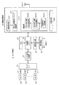
以下、この発明によるセンサネットワークシステムの実施形態を、図を参照しながら説明する。図1は、この実施形態のセンサネットワークシステムの全体の構成の概要を説明するための図である。 Hereinafter, embodiments of a sensor network system according to the present invention will be described with reference to the drawings. FIG. 1 is a diagram for explaining the outline of the entire configuration of the sensor network system of this embodiment.
図1において、この例では四角で囲んで示すエリア1は、この実施形態におけるシステムの監視対象のエリア(以下、監視エリアという)であり、コンビニエンスストアやスーパーやデパートの同一フロアの売り場全体、あるいは工場やオフィス空間などである。監視エリア1は、平面的なエリアではなく、互いに直交する横方向(X方向)、縦方向(Y方向)、高さ方向(Z方向)からなる3次元の空間エリアであり、図1は、高さ方向を省略した図である。なお、監視エリア1の空間形状は、X方向及びY方向で規定されるエリアが、図1の例のような四角形で囲まれるものに限られるものではなく、任意の空間形状で良いことは言うまでもない。
In FIG. 1, an
この監視エリア1内には、複数のセンサ端末21〜2nと、複数の中継装置31〜3mが配設される。複数のセンサ端末21〜2nのそれぞれは、例えば、事前に策定される環境監視計画に応じて、監視エリア1内の、予め定められた位置に配設される。監視エリア1内を、その位置の違いに応じて詳細に監視するためには、監視エリア1内には、多数のセンサ端末2を異なる位置に配設する必要がある。そこで、この実施形態では、センサ端末21〜2nは、例えば1000個(n=1000)が、監視エリア1内に配設可能とされている。しかし、図1では、紙面の都合上、6個(n=6)のセンサ端末21〜26が、監視エリア1内に配設されている。
In this
複数のセンサ端末21〜2nは、自立電源により駆動するもので、全く同様の構成を有する。そこで、以下の説明において、センサ端末21〜2nのそれぞれを区別する必要のないときには、便宜上、センサ端末2と記載する。
The plurality of
センサ端末2には、検知対象が異なる複数種のセンサが同時に接続可能とされている。センサの検出対象は、当該監視エリア1の空間環境の環境要素、例えば温度、塵埃量、気流、照明の照度、消費電力などとされ、各センサは、その検出対象の検出出力としてのセンシングデータを、センサ端末2に出力する。センサ端末2は、これに接続されているセンサからのセンシングデータを、順時に所定のタイミングで取り込み、当該取り込んだセンシングデータを、そのセンサ種別を示す識別情報(センサID)と共に、無線送信する機能を有する。
A plurality of types of sensors having different detection targets can be connected to the
中継装置31〜3mのそれぞれは、この実施形態では、監視エリア1内において、監視エリア1内に配設された複数のセンサ端末21〜2nから無線送信信号を受信することができるような位置であって、互いに異なる位置に配設されている。この実施形態では、複数の中継装置31〜3mのそれぞれは、通信網4を通じて監視センタ装置5に接続されている。通信網4は、既設の電話回線など有線による通信ネットワークでも良いし、無線による通信ネットワークでもよい。また、通信網4は、LAN(Local Area Network)の構成であっても良いし、WAN(Wide Area Network)の構成であっても良い。
In this embodiment, each of the
中継装置31〜3mのそれぞれは、センサ端末21〜2nのそれぞれからの送信信号を受信し、その受信した送信信号に、後述するような所定の情報を付加した後、通信網4を通じて監視センタ装置5に転送する。なお、複数個の中継装置31〜3mは同じ構成を備えるものであり、以下の説明において、複数個の中継装置31〜3mのそれぞれを区別する必要がないときには、便宜上、中継装置3と記述する。
Each of the
中継装置31〜3mのそれぞれは、複数のセンサ端末21〜2nからの送信信号を受信して監視センタ装置5に転送するので、監視センタ装置5には、同じセンサ端末からの送信信号が、最大、中継装置31〜3mの数分だけ送られることになる。なお、中継装置31〜3mのそれぞれは、必ずしも監視エリア1内に配設された全てのセンサ端末2からの無線送信信号を受信することができなくてもよく、後述するように、監視センタ装置5に、同じセンサ端末2からの送信信号を、中継装置31〜3mのうちの少なくとも3個の中継装置から転送することができるように配設されていれば良い。
Since each of the
この実施形態においては、センサ端末2は、自立電源の電力消費を低減するために、取り込んだセンシングデータを、間欠的に無線送信する。この場合に、中継装置3は、複数個のセンサ端末2からのセンシングデータを、確実且つ信頼性良く受信して、監視センタ装置5に転送することが肝要である。
In this embodiment, the
そのための方策として、従来は、センサ端末からの送信信号にエラー検出符号の付加、エラー検出時のセンシングデータの再送、送受信間で同期を取る方法、などが一般的に採用されている。しかし、エラー検出時にセンシングデータの再送をするためには、センサ端末2が、中継装置3からのエラー通知を受け取るための受信部を備える必要があり、その分、消費電力が増加してしまう。また、送信信号にエラー訂正符号を付加する方法では、そのエラー訂正符号の分だけ、送信情報が増加して、送信時間が増加し、それも消費電力の増加に繋がる。また、送受信間で同期を取る方法を採用する場合には、当該同期を取るための構成が特に必要となり、構成が複雑となってしまう。
As measures for this, conventionally, an error detection code is added to a transmission signal from a sensor terminal, sensing data is retransmitted when an error is detected, a method of synchronizing between transmission and reception, and the like are generally employed. However, in order to retransmit sensing data when an error is detected, it is necessary for the
以上のことに鑑み、この実施形態では、センサ端末2と中継装置3との間の無線通信は、非同期として、エラー検出符号などの付加は伴わず、また、センサ端末2は、中継装置3からの信号を受信する機能を備えていない。センサ端末2は、センサ端末の識別情報(端末ID)及びセンサの識別信号(前述のセンサID)とセンシングデータとを、非同期で送出する機能を備えるだけの簡単な構成とされている。
In view of the above, in this embodiment, the wireless communication between the
一方、中継装置3は、センサ端末2からの送信信号を常に監視して、センサ端末2からの送信信号を受信したと判別したときには、当該送信信号を取り込むことで、非同期で送られてくるセンサ端末からの送信信号を確実に受信して、監視センタ装置5に転送するようにしている。
On the other hand, when the
しかし、この場合に、センサ端末2と中継装置3との間の通信は非同期であると共に、監視エリア1内に配設可能なセンサ端末2の数が1000個と言うように多数であることから、それら多数個のセンサ端末2からの間欠送信の開始タイミングが重なって、送信信号が衝突して恐れがあることを考慮しなければならない。このような送信信号の衝突が生じると、センサ端末2からのセンシングデータを受信できなくなって、監視センタ装置5での監視結果についての信頼性が低下することになる。
However, in this case, the communication between the
このことに鑑み、この実施形態では、センサ端末2のそれぞれは乱数発生器を備え、その乱数発生器からの乱数値により間欠送信の開始タイミングを決定することで、間欠送信の開始タイミングが、互いに重ならないようにしている。
In view of this, in this embodiment, each of the
また、中継装置3でセンサ端末2からの送信信号を、より確実に受信することができるようにして信頼性を向上させるために、この実施形態では、センサ端末2は、同一の情報を、互いに異なる周波数帯域の送信信号として、複数回、時分割で送出するようにする。具体的には、後で詳述するが、この実施形態では、センサ端末2は、間欠送信のタイミングでは、315MHz帯で送信情報を送出した後、引き続いて920MHz帯で、再度、同じ送信情報を送出するようにする。
Further, in order to improve the reliability by enabling the
また、この実施形態では、センサ端末2における自立電源の電力消費を、極力抑えることができるような工夫が更に加えられている。
Moreover, in this embodiment, the device which can suppress the power consumption of the independent power supply in the
すなわち、後述するように、監視センタ装置5では、センサ端末2からのセンシングデータを、その取得時点(発生時点)と対応付けて格納して時系列データとして管理するようにする必要があるが、そのために、センサ端末2からのセンシングデータには、その取得時点の情報が必要になる。一般的には、センサ端末2がセンサから取り込んだ時点の情報を送信信号に含めて、中継装置3を通じ、通信網4を通じて、監視センタ装置5に転送する。しかし、それでは、センサ端末2から送信する情報が多くなり、その分だけ、電力消費も大きくなってしまう。
That is, as described later, in the
そこで、この実施形態では、センサ端末2は、センシングデータの取得時点の情報を含めずに中継装置3に送信する。そして、中継装置3で、センサ端末2の送信信号を受信した時点を、当該センサ端末2からの送信信号に含まれるセンシングデータの取得時点とし、この受信時点の情報を、センシングデータの情報と共に、監視センタ装置5に転送するようにする。
Therefore, in this embodiment, the
なお、監視センタ装置は、自装置がセンサ端末からの送信信号を受信した時刻を、センシングデータの取得時刻の情報として用いるようにしてもよい。 Note that the monitoring center device may use the time at which the own device receives the transmission signal from the sensor terminal as information on the sensing data acquisition time.
また、この実施形態では、後述するように、監視センタ装置5では、監視エリア1内におけるセンサ端末21〜2nのそれぞれの配設位置を把握することで、監視エリア1内の異なる位置での環境状況を詳細に判定して、当該環境状況を見える化処理するようにする。そのためには、センサ端末21〜2nのそれぞれの監視エリア1内における位置情報が必要となる。しかし、センサ端末21〜2nのそれぞれの位置情報を送信信号に含めるようにすると、上述したように、センサ端末21〜2nのそれぞれから送信する情報が多くなり、その分だけ、電力消費も大きくなってしまう。
Further, in this embodiment, as will be described later, the
そこで、この実施形態では、センサ端末21〜2nのそれぞれは、監視エリア1内の配設位置情報は、送信信号には含めない。その代わりに、中継装置3において、監視センタ装置5で、センサ端末21〜2nのそれぞれの監視エリア1内の配設位置を算出することができるようにするための情報を付加するようにする。
Therefore, in this embodiment, each of the
すなわち、この例の場合に、中継装置31〜3mのそれぞれは、互いに異なる位置に配設されているので、センサ端末21〜2nのそれぞれからの距離が互いに異なる。中継装置31〜3mのそれぞれがセンサ端末21〜2nのそれぞれから受信する送信信号の電波強度は、中継装置31〜3mのそれぞれと、センサ端末21〜2nのそれぞれとの距離の違いに応じたものとなっている。
That is, in the case of this example, each of the
この実施形態では、中継装置3は、センサ端末21〜2nのそれぞれからの送信信号を受信したときに、その電波強度を検出する。そして、中継装置3は、この電波強度の情報を、センサ端末21〜2nのそれぞれから受信した受信信号に付加して、監視センタ装置5に転送する。
In this embodiment, the
この実施形態では、監視センタ装置5は、センサ端末21〜2nのそれぞれの監視エリア1内の配設位置を算出することができるようにするための情報として、この電波強度の情報を用いる。すなわち、監視センタ装置5は、中継装置31〜3mのそれぞれから送られてくる電波強度の情報から、中継装置31〜3mのそれぞれと、センサ端末21〜2nのそれぞれとの距離を算出する。そして、中継装置31〜3mの監視エリア1内における配設位置を、監視センタ装置5に登録しておくことで、監視センタ装置5は、それらの中継装置の位置情報と、中継装置31〜3mのそれぞれと、センサ端末21〜2nのそれぞれとの距離とから、それぞれのセンサ端末21〜2nの監視エリア1内での位置を検出するようにする。
In this embodiment, the
監視センタ装置5で、センサ端末21〜2nの監視エリア1内での位置(高さも含む)を検出することができるためには、中継装置31〜3mは、少なくとも3個が監視エリア1内に配設されている必要がある。図1の例では、便宜上、監視エリア1内には、3個の中継装置31〜33が配置されている場合としている。
In order for the
以上のようにして、この実施形態では、センサ端末2は、送出する送信データ量をできるだけ少なくして、自立電源の低消費電力化を図るようにしている。
As described above, in this embodiment, the
監視センタ装置5は、以上のようにして、複数個のセンサ端末21〜2nのそれぞれからのセンシングデータを、中継装置31〜3mを介して受信し収集する。この場合に、前述したように、監視センタ装置5には、同じセンサ端末2からの同一の情報内容の送信信号が、複数個の中継装置3から送られてくる。監視センタ装置5は、同じセンサ端末2からの同一の情報内容の送信信号を複数個、受信したときには、この実施形態では、電波強度の情報を参照して、もっとも、電波強度の大きいセンシングデータを、蓄積するセンシングデータとして選択する。この場合に、監視センタ装置5は、各センシングデータを、中継装置31〜3mで付加されたその受信時点を取得時点として、その取得時点の情報と対応付けることにより時系列データとして収集し、蓄積する。
As described above, the
監視センタ装置5で蓄積するセンシングデータを選択する方法は、電波強度の大きさに応じた方法とする場合に限定されるわけではなく、例えば、同一の情報内容の送信信号の内の任意の1個を蓄積するようにしても、勿論よい。
The method of selecting the sensing data stored in the
また、監視センタ装置5は、上述したように、複数個の中継装置31〜3mから送られてくる同じセンサ端末2からの同一の情報内容の送信信号についての電波強度のそれぞれを抽出し、それらと、予め記憶している複数個の中継装置31〜3mの監視エリア1内の位置情報とを用いて、それぞれのセンサ端末2の監視エリア1内の位置を算出して保持する。
Further, as described above, the
そして、蓄積したセンサ端末21〜2nからの各センサのセンシングデータの時系列データと、当該センサ端末21〜2nの監視エリア1内の位置情報とから、監視エリア1内の各センサ端末21〜2nの位置における、当該センシングデータから判定できる環境情報を見える形の表示情報に変換して、表示画面に表示する。
Then, each sensor in the
監視センタ装置5のオペレータは、この表示画面の見える化情報を見ることで、監視エリア1内の、当該センシングデータにより知得できる環境情報の時系列変化を把握することができる。したがって、前記オペレータは、その把握結果に応じて、監視エリア1で生じた環境変化に応じた適切な判断をして、適切な指示をすることができる。
The operator of the
次に、以上説明したシステムにおけるセンサ端末2、中継装置3及び監視センタ装置5の詳細な構成及び詳細な処理動作について更に説明する。
Next, detailed configurations and detailed processing operations of the
[センサ端末2の説明]
図2は、センサ端末2のハードウエア構成例を示すブロック図である。図2に示すように、センサ端末2は、マイクロコンピュータにより構成されてセンサ端末2の全体を制御するための制御部20と、センサインターフェース21と、センサ信号処理部22と、メモリ23、無線送信部24と、自立電源25と、電圧検出部26とを備える。
[Description of sensor terminal 2]
FIG. 2 is a block diagram illustrating a hardware configuration example of the
センサインターフェース21は、この例では、例えば7個のセンサ接続端子211,212,・・・,217を備える。この7個の接続端子211〜217のそれぞれには、それぞれの接続端子毎にセンサ種別が予め定められた7種類のセンサ61,62,・・・,67を接続可能である。例えば、センサ61は赤外線アレーセンサ(温度センサ)、センサ62は塵埃センサ、センサ63は炭酸ガス濃度センサ、センサ64はVOC(Volatile Organic Compounds;揮発性有機化合物)濃度センサ、センサ65は電流・磁界センサ・・・などとされる。これらのセンサ61〜67は、この実施形態では、MEMS(Micro Electro Mechanical System)技術により構成された小型のものとされる。センサ接続端子211〜217の全てにセンサを接続する必要はなく、監視したい環境要素に対応したセンサ種別のセンサのみを選択して接続するようにすることができる。
In this example, the
センサインターフェース21は、センサ信号処理部22を通じて制御部20に接続されている。センサ信号処理部22は、制御部20の制御を受けて、センサ接続端子211〜217に接続されているセンサからのセンシングデータを、センサインターフェース21から取得して、制御部20に供給するようにする。
The
制御部20は、センサの種別に応じて定められた適宜のそれぞれのタイミングで各センサのセンシングデータを取り込み、その取り込んだセンシングデータを、センサの種別に応じて定められた周期で間欠的にそれぞれ送信するように制御する。すなわち、この実施形態では、制御部20は、センサの種別に応じたタイミングで外部センサの起動、停止及びセンシングデータの取り込みの制御を行うと共に、センサの種別に応じた間欠周期でのセンシングデータの無線送信の起動、停止及びセンシングデータの一時的な記録・保存を制御する。
The
なお、各センサ毎に、センシングデータの間欠的な無線送信のタイミングと、センシングデータの取り込みタイミングを同期させても良いが、この実施形態では、両タイミングは、非同期で、その繰り返し周期も、それぞれ個別に設定可能としている。 Note that the timing of intermittent wireless transmission of sensing data and the timing of capturing sensing data may be synchronized for each sensor, but in this embodiment, both timings are asynchronous and the repetition cycle is also respectively It can be set individually.
そして、この実施形態では、制御部20は、各センサからのセンシングデータを、そのセンサの種類に応じた周期タイミングで取り込んで、後述するセンサ種別毎に予め定められたイベント発生条件の状態となったか否かを監視するようにしている。例えば、制御部20は、赤外線アレーセンサ61からのセンシングデータから「温度が急激に変化した」というイベント発生条件を満たす状態になった時点では、当該時点が間欠送信タイミングではなくても、赤外線アレーセンサ61からのセンシングデータを、即座に無線送信すると共に、その後の間欠無線送信の間欠周期を短い周期に変更する、などの処理を行う。
In this embodiment, the
また、あるセンサのセンシングデータについて、そのイベント発生条件に合致する状態になったときに、当該センサのセンシングデータを即座に無線送信すると共に、その間欠無線送信の周期を変更するだけでなく、関連付けられた他のセンサのセンシングデータについても同様の処理をするようにする。例えば、炭酸ガスセンサ63からのセンシングデータが、「炭酸ガス濃度が所定値を超えた」というイベント発生条件を満たす状態になった時点では、当該炭酸ガスセンサ63からのセンシングデータのみでなく、赤外線アレーセンサ61及びVOC濃度センサ64からのセンシングデータを、即座に無線送信すると共に、その後の間欠無線送信の間欠周期を短い周期に変更する、などの処理を行う。
In addition, when sensing data of a sensor is in a state that matches the event occurrence condition, the sensor sensing data of the sensor is immediately wirelessly transmitted, and not only the intermittent wireless transmission period is changed, but also the association is performed. The same processing is performed on the sensing data of the other sensors. For example, when the sensing data from the carbon dioxide sensor 63 reaches a state where the event occurrence condition “the carbon dioxide concentration exceeds a predetermined value” is satisfied, not only the sensing data from the carbon dioxide sensor 63 but also the
制御部20は、以上のようなタイミング制御のために、センサインターフェース21のセンサ接続端子211〜217のそれぞれに接続されたセンサのセンシングデータを取り込む指示を、センサ信号処理部22に送って、その取り込まれたセンシングデータを受け取り、メモリ23に一時保持格納する。そして、このメモリ23に格納しているセンシングデータを用いて、センサ種別毎に予め定められたイベント発生条件に合致する状態になったか否かを監視する。
For the timing control as described above, the
また、制御部20は、センサの種別毎の間欠無線送信タイミングを管理しており、あるセンサの間欠無線送信を開始するタイミングになると、そのセンサの最新のセンシングデータをメモリ23から読み出し、そのセンシングデータを、間欠無線送信の開始指示と共に、無線送信部24に送る。このとき、制御部20からは、送信しようとしているセンサ種別の情報も、無線送信部24に送られる。
In addition, the
無線送信部24は、間欠送信開始タイミング制御部241と、乱数発生器242と、変調部243と、ID割付部244とを備えている。
The wireless transmission unit 24 includes an intermittent transmission start
間欠送信開始タイミング制御部241は、制御部20からの間欠送信開始指示を受けて、乱数発生器242からの乱数値に基づいて、送信開始タイミングを決定する。すなわち、ある種別のセンサの間欠送信の周期は、制御部20では、当該センサ種別に応じた周期とされるが、この実施形態では、多数個のセンサ端末2から任意に送信信号が送出されるので、同じ種別のセンサについての間欠送信のタイミングが、異なるセンサ端末2で重なってしまうおそれがある。そのような場合には、中継装置3では、衝突して重なって受信された情報信号を分離することが困難になる。そこで、この実施形態では、このような複数のセンサ端末2からのセンサの送信タイミングが重なって衝突を起こす状態を、乱数発生器242からの乱数値を用いることで、できるだけ回避するようにしている。
The intermittent transmission start
図3は、ある種別のセンサについての間欠送信の周期及び開始タイミングの制御を説明するための図である。すなわち、この図3(A)に示すように、この例のセンサの通常状態における無線送信の間欠周期はTnとされ、この間欠周期Tn毎に、制御部20から、無線送信部24に、その送信開始指示が送られる。間欠周期Tnは、赤外線アレーセンサ61の場合には、例えば数分〜10分程度とされている。
FIG. 3 is a diagram for explaining control of the intermittent transmission cycle and start timing for a certain type of sensor. That is, as shown in FIG. 3 (A), the intermittent period of wireless transmission in the normal state of the sensor of this example is Tn, and the
無線送信部24では、この送信開始指示を受け取ると、間欠送信開始タイミング制御部241は、乱数発生器242の乱数値を参照し、当該送信開始指示を受けた時点からの遅延時間D1,D2,D3・・・のそれぞれを、この乱数値に基づいて定め、その遅延時間D1,D2,D3・・・経過した時点を、実際の無線送信開始タイミングとする。この遅延時間D1,D2,D3・・・のそれぞれは、ゼロまたは、後述する無線送信を完了するまでの送信区間の時間長TXの整数倍の時間とされている。なお、送信区間の時間長TXは、後述するように、この例では、TX=2ミリ秒とされている。
When the wireless transmission unit 24 receives this transmission start instruction, the intermittent transmission start
また、制御部20は、このセンサ種別に関連するイベントの発生を検知すると、図3(B)に示すように、当該イベントの発生時点において、送信開始指示を無線送信部24に送る。そして、制御部20は、その後は、図3の例では、間欠周期を、通常状態における周期Tnよりも短い周期Teに変更して、送信開始指示を無線送信部24に送る。
Further, when detecting the occurrence of an event related to this sensor type, the
したがって、無線送信部24では、イベント発生直後に送信信号の送出を行う。そして、イベント発生後においては、無線送信部24は、制御部20からの、短い周期Teで送信開始指示を受け取る毎に、間欠送信開始タイミング制御部241が、乱数発生器242の乱数値を参照して遅延時間D4,D5,D6・・・を定めて、無線送信を実行するようにする。他の種別のセンサのセンシングデータの間欠送信についても、その間欠周期の違いはあるが、同様のタイミング制御がなされる。
Accordingly, the wireless transmission unit 24 transmits a transmission signal immediately after the event occurs. After the event occurs, every time the wireless transmission unit 24 receives a transmission start instruction from the
なお、制御部20は、イベント発生条件が合致する状態を検出できなくなったときには、送信開始指示のタイミングを、通常状態の間欠周期Tnに戻す。
Note that the
以上のように、この実施形態では、センサ端末2は、センサ種別毎に所定の間欠周期を定めているが、実際の間欠の無線送信タイミングは、乱数値に基づいた送信区間の時間長の整数倍だけ遅延された時点とされ、一定周期のものではなくなる。したがって、もしも、他のセンサ端末2と、制御部20で決められる間欠送信開始の指示タイミングが同一時点になったとしても、実際の無線送信においては、衝突する確率が低くなるという効果がある。
As described above, in this embodiment, the
また、この実施形態では、センサ種別に対応付けられたイベントが発生したときには、その対応付けられたセンサのセンシングデータが、そのイベント発生時に送出されると共に、当該イベントの発生条件が合致している状態のときには、間欠送信の周期を、通常状態の周期よりも短くしている。したがって、この実施形態では、監視センタ装置5では、イベント発生後の状況を、より詳細に監視することができるようになる。
Further, in this embodiment, when an event associated with a sensor type occurs, sensing data of the associated sensor is transmitted when the event occurs, and the occurrence conditions of the event match. In the state, the intermittent transmission cycle is shorter than the cycle in the normal state. Therefore, in this embodiment, the
無線送信部24の変調部243は、この実施形態では、周波数を変化させるFSK(Frequency Shift Keying;周波数偏移変調)を用いると共に、このFSKで用いる周波数を、例えば100値以上の多値とした多値FSKと、CCK(Complementary Code Keying;相補型符号変調)とを組み合わせた新規の変調方式を採用している。また、この実施形態のセンサ端末2では、微弱無線規格に適合する無線送信を採用するものであり、また、周波数帯域として、315MHz帯と920MHz帯を使用する。
In this embodiment, the
この実施形態の変調部243は、前述した多値FSKとCCKとを組み合わせた新規の変調方式を実現するために、拡散符号決定部2431と、315MHz帯FSK処理部2432と、920MHz帯FSK処理部2433とを備える。
The
そして、この実施形態においては、多数のセンサ端末2からの間欠無線送信電波の衝突を避けるために、センサ端末2からの送信データ量を少なくして、間欠的な無線送信における送信区間の時間長を、できるだけ短くしている。そのため、センサ端末2から無線送信する送信データDAは、同期用データやエラー検出又はエラー訂正用のパリティデータは含まず、図4(A)に示すように、端末IDと、センサIDと、センシングデータとからなる必要最小限のデータのみで構成するようにしている。
In this embodiment, in order to avoid collision of intermittent wireless transmission radio waves from a large number of
この例では、センサ端末2の数は、1000個を想定しているので、端末IDは、10ビット、センサ種類は7個を想定しているので、センサIDは3ビットとされ、センシングデータは、例えば23ビットとされる。したがって、送信データDAは、合計36ビットのデータとされる。なお、センサIDは3ビットとされるので、センサIDが一つ余る。この一つ余ったセンサIDは、この実施形態では、後述するように、センサ端末2の自立電源25の蓄電量(電源状況)を監視センタ装置5に伝達するために用いられる。
In this example, since the number of
ID割付部244は、自センサ端末の端末IDを記憶していると共に、センサの種別に対応する複数個のセンサIDを記憶している。そして、制御部20から、間欠送信開始指示と共に送られてくるセンサ種別の情報に基づいて、ID割付部244は、自センサ端末の端末IDと共に、そのセンサ種別に対応するセンサIDを読み出して、変調部243に送る。変調部243は、制御部20から送られてくるセンシングデータと、ID割付部244から供給されてくる端末ID及びセンサIDとを合成して、送信データDAを生成し、生成した送信データDAに対して以下に説明するように変調処理を施す。
The
[変調部243での変調処理]
この変調部243での変調処理について、図2に加え、図4(B)及び(C)をさらに参照しながら説明する。この実施形態では、36ビットの送信データDAを、18ビット毎のデータに2分割する。そして、18ビット毎のデータについて、以下に説明するようにして、多値FSKとCCKとを組み合わせた変調処理を施す。
[Modulation Processing in Modulation Unit 243]
The modulation processing in the
先ず、変調部243の拡散符号決定部2431は、図4(B)及び(C)に示すように、18ビットのデータの先頭の2ビットから、2ビットの符号パターンに応じた4チップの拡散符号を決定する。
First, as shown in FIGS. 4B and 4C, the spreading
この場合に、拡散符号決定部2431は、2ビットのデータの4個の符号列パターン[00]、[01]、[10]、[11]のそれぞれに対応して、4チップの拡散符号の符号列パターンを定めて記憶している。この例においては、図4(C)に示すように、2ビットのデータの4個の符号列パターン[00]、[01]、[10]、[11]のそれぞれと、4チップの拡散符号の符号列パターン[1000]、[0001]、[0010]、[0100]のそれぞれとを、互いに対応付けて記憶している。そして、拡散符号決定部2431は、先頭の2ビットのデータに対応する4チップの符号列パターンを拡散符号として決定する。18ビットのデータが、図4(B)に示すように、[010100011010010011]の場合であれば、拡散符号決定部2431は、先頭の2ビットのデータ[01]に対応する4チップの符号列パターン[0001]を拡散符号として決定する。
In this case, the spread
次に、変調部243の315MHz帯FSK処理部2432は、先頭の2ビットを除く16ビットのデータに対して、拡散符号決定部2431で決定された拡散符号のチップの符号値「0」に対して割り付ける周波数と、チップの符号値「1」に割り付ける周波数とを決定し、その決定した周波数を、拡散符号決定部2431で決定した拡散符号の4チップの符号列パターンに対応して出力する。
Next, the 315 MHz band
この実施形態では、図4(C)に示すように、315MHz帯FSK処理部2432は、周波数決定部2432aと、周波数発生部2432bと、出力アンプ2432cとを備える。
In this embodiment, as shown in FIG. 4C, the 315 MHz band
周波数決定部2432aは、18ビットのデータの先頭の2ビットを除く16ビットのデータに対して、拡散符号決定部2431で決定された拡散符号のチップの符号値「0」に対して割り付ける周波数と、チップの符号値「1」に割り付ける周波数とを決定する。この実施形態では、周波数決定部2432aは、18ビットのデータの先頭の2ビットを除く16ビットのデータの前半の8ビットの256通りの符号列パターンに基づいて、拡散符号のチップの符号値「0」を割り付ける周波数を決定し、後半の8ビットの符号列パターンに基づいて、拡散符号のチップの符号値「1」を割り付ける周波数を決定する。
The
この実施形態では、周波数決定部2432aは、周波数が310.0MHz〜322.80MHzの間において、0.05MHz間隔で、256個の異なる周波数を送信周波数として想定する。周波数決定部2432aは、図4(C)に示すように、16ビットのデータの符号列パターンのそれぞれと、その前半の8ビットの符号列パターンにより定まる拡散符号のチップの符号値「0」を割り付ける周波数、及び後半の8ビットの符号列パターンにより定まる拡散符号のチップの符号値「1」を割り付ける周波数の組みとの対応テーブルを記憶している。この場合、拡散符号のチップの符号値「0」を割り付ける周波数と、拡散符号のチップの符号値「1」を割り付ける周波数とは互いに異なるようにしており、このため、図4(C)に示すように、拡散符号のチップの符号値「0」を割り付ける周波数が決まると、その周波数の符号値「0」と組み合わされる拡散符号のチップの符号値「1」を割り付ける周波数は255通りとなっている。
In this embodiment, the
例えば、図4(C)の周波数決定部2432aに示すように、拡散符号のチップの符号値「0」が割り付けられる16ビットの前半の8ビットの符号列パターンが、[00000000]に対しては、310.0MHzの周波数が割り当てられる。したがって、このチップの符号値「0」と組となるチップの符号値「1」が割り付けられる周波数は、310.00MHzを除く、310.05MHzから0.05MHz間隔で322.80MHzまでに設定される255通りの周波数となる。
For example, as shown in the
周波数決定部2432aは、この対応テーブルを用いて、先頭の2ビットを除く16ビットのデータに対応する拡散符号のチップの符号値「0」に割り付ける周波数と、符号値「1」に割り付ける周波数を決定する。例えば、図4(B)に示すように、送信データの先頭の2ビットを除く16ビットのデータが、[0100011010010011]である符号列パターンに対しては、周波数決定部2432aは、拡散符号のチップの値「0」に対応する周波数f[0]は、f[0]=315.00MHzと決定し、拡散符号のチップの値「1」に対応する周波数f[1]は、f[1]=317.05MHzと決定する。
Using this correspondence table, the
そして、この周波数決定部2432aで決定された周波数f[0]及び周波数f[1]の情報を、周波数発生部2432bに供給する。また、拡散符号決定部2431で決定された拡散符号の4チップの符号列パターンも、周波数発生部2432bに供給する。
Then, information on the frequency f [0] and the frequency f [1] determined by the
周波数発生部2432bは、例えばPLL(Phase Rock Loop)からなる可変周波数発振器を備え、拡散符号決定部2431からの拡散符号の4チップの符号列パターンの符号値「0」、「1」に応じて、周波数決定部2432aで決定された対応する周波数を出力する。そして、この周波数発生部2432bから出力された周波数の信号は、出力アンプ2432cを通じて送信アンテナATに供給されて無線送信される。
The
36ビットの送信データDAの後半の18ビットのデータについても、変調部243の拡散符号決定部2431及び315MHz帯FSK処理部2432において、全く同様の処理がなされて、その18ビットのデータに応じて定められた周波数の信号に変換されて、出力アンプ2432cを通じて送信アンテナATに供給されて無線送信される。
The 18-bit data in the latter half of the 36-bit transmission data DA is also subjected to exactly the same processing in the spreading
なお、上述の例においては、送信データの先頭の2ビットを拡散符号に割り当てるようにしたが、この2ビットの位置は、送信データの先頭に限らず、任意の位置で良い。また、上述の例では、18ビットの送信データについて説明したが、これは一例であり、送信データのビット数は、これに限られるものではなく、任意のビット数でよいことは言うまでもない。 In the above example, the first 2 bits of the transmission data are assigned to the spread code. However, the position of these 2 bits is not limited to the beginning of the transmission data, and may be an arbitrary position. In the above example, 18-bit transmission data has been described. However, this is only an example, and it goes without saying that the number of bits of transmission data is not limited to this, and may be any number of bits.
また、拡散符号は送信データ中の2ビットに割り当てるのではなく、送信データ中の3ビット以上に割り当ててもよい。 Further, the spreading code may be assigned to 3 bits or more in the transmission data instead of being assigned to 2 bits in the transmission data.
また、上述の例では、多値FSKにおいては、16ビットのデータの前半の8ビットと後半の8ビットのそれぞれを、拡散符号のチップの符号値の[0]及び[1]に割り当てることとして、256通りの周波数を、16ビットのデータに割り当てるようにした。しかし、多値FSKの複数個の周波数を割り当てるデータのビット数は、任意であり、割り当てるデータのビット数に応じて、多値FSKで使用する周波数の数は定まる。 In the above example, in multi-level FSK, the first 8 bits and the last 8 bits of 16-bit data are assigned to the code values [0] and [1] of the spread code chip, respectively. 256 frequencies are assigned to 16-bit data. However, the number of bits of data to which a plurality of frequencies of multi-level FSK is allocated is arbitrary, and the number of frequencies used in multi-level FSK is determined according to the number of bits of data to be allocated.
920MHz帯FSK処理部2433は、315MHz帯FSK処理部2432と、同様の構成を備える。ただし、この920MHz帯FSK処理部2433においては、920MHz帯において出力できる上限の電界強度が小さいため、同時使用可能な周波数チャンネル数は制限され、多値FSKで使用する周波数は少なくする必要がある。
The 920 MHz band
このため、この例の920MHz帯FSK処理部2433における多値FSKとCCKとを組み合わせた変調方式においては、送信データ中のCCKに割り当てるビット数を多くすることで、多値FSKに割り当てるビット数を少なくして、多値FSKで使用する周波数を少なくする方法を用いる。
For this reason, in the modulation scheme combining multilevel FSK and CCK in the 920 MHz band
あるいは、920MHz帯FSK処理部2433における多値FSKとCCKとを組み合わせた変調方式においては、CCKに割り当てるビット数は変えず、その代わりに、送信データを、上述の例のような2分割ではなく、この場合の多値FSKで使用可能な周波数に応じたビット数毎に、更に細かく分割して、その分割数だけ送信を行うようにしても良い。この例の場合には、送信区間が長くならないようにするために、送信ビットレートを上げるようにすると良い。
Alternatively, in the modulation scheme that combines multilevel FSK and CCK in the 920 MHz band
920MHz帯FSK処理部2433は、315MHz帯FSK処理部2432で処理するのと同じ36ビットの送信データDAを、上述のように処理して、920MH帯の周波数の信号に変換して、送信アンテナATに供給し無線送信する。
The 920 MHz band
この実施形態では、センサ端末2は、図5に示すように、間欠送信の開始時点から2ミリ秒の間の送信区間TXに、送信データDAを、315MHz帯と、920MHz帯とで送信する。すなわち、この実施形態では、無線送信部24は、間欠送信の開始時点になると、送信区間TXの前半の1ミリ秒の間は、変調部243の315MHz帯FSK処理部2432で、送信データDAを、前述したように多値FSKとCCKとを組合せた変調方式により変調して得られた周波数信号を無線送信信号として送出する。
In this embodiment, as shown in FIG. 5, the
そして、この1ミリ秒が経過したときには、無線送信部24は、変調部243の920MHz帯FSK処理部2433で、同じ送信データDAを、前述したように多値FSKとCCKとを組合せた変調方式により変調して得られた周波数信号を無線送信信号として送出する。
Then, when 1 millisecond has elapsed, the radio transmission unit 24 uses the 920 MHz band
この例の場合、センサ端末2から無線送信される周波数信号は、図5に示すように、315MHz帯と、920MHz帯とにおいて、常に単一の周波数の信号となる。例えば36ビットの送信データDAの前半の18ビットの先頭の2ビットから決定された4チップの拡散符号が[0001]で、後半の18ビットの先頭の2ビットから決定された4チップの拡散符号が[1100]である場合を例に取ると、無線送信信号は、図5に示すような周波数遷移をするものとなる。
In this example, the frequency signal wirelessly transmitted from the
すなわち、変調部243の315MHz帯FSK処理部2432は、送信データDAの前半の18ビットの先頭の2ビットを除く16ビットから、拡散符号のチップの符号値「0」に割り付ける周波数として周波数faを決定し、符号値「1」に対応する周波数として周波数fb(fa≠fb)を決定する。そして、変調部243の315MHz帯FSK処理部2432は、送信データDAの前半の18ビットの先頭の2ビットから決定された4チップの拡散符号[0001]に対応して、図5に示すように、周波数fa→周波数fa→周波数fa→周波数fbを無線送信信号として送出する。
That is, the 315 MHz band
そして、これに引き続いて、変調部243の315MHz帯FSK処理部2432は、送信データDAの後半の18ビットの先頭の2ビットを除く16ビットから、拡散符号のチップの符号値「0」に割り付ける周波数として周波数fcを決定し、符号値「1」に対応する周波数として周波数fd(fc≠fd)を決定する。このとき、送信データDAの前半の18ビットの先頭の2ビットを除く16ビットと、送信データDAの後半の18ビットの先頭の2ビットを除く16ビットとが同じである場合にはfc=fa及びfd=fbであり、異なる場合には、fc≠fa及びfd≠fbである。
Subsequently, the 315 MHz band
そして、変調部243の315MHz帯FSK処理部2432は、送信データDAの後半の18ビットの先頭の2ビットから決定された4チップの拡散符号[1100]に対応して、図5に示すように、周波数fd→周波数fd→周波数fc→周波数fcを無線送信信号として送出する。
Then, the 315 MHz band
そして、変調部243の920MHz帯FSK処理部2433は、同じ36ビットの送信データDAについて無線送信を行うので、送信データDAの前半の18ビットの先頭の2ビットを除く16ビットから、拡散符号のチップの符号値「0」に割り付ける周波数として周波数feを決定し、符号値「1」に対応する周波数として周波数ff(fe≠ff)を決定する。そして、変調部243の920MHz帯FSK処理部2433は、送信データDAの前半の18ビットの先頭の2ビットから決定された4チップの拡散符号[0001]に対応して、図5に示すように、周波数fe→周波数fe→周波数fe→周波数ffを無線送信信号として送出する。
Then, the 920 MHz band
これに引き続いて、変調部243の920MHz帯FSK処理部2433は、送信データDAの後半の18ビットの先頭の2ビットを除く16ビットから、拡散符号のチップの符号値「0」に割り付ける周波数として周波数fgを決定し、符号値「1」に対応する周波数として周波数fh(fg≠fh)を決定する。そして、変調部243の920MHz帯FSK処理部2433は、送信データDAの後半の18ビットの先頭の2ビットから決定された4チップの拡散符号[1100]に対応して、図5に示すように、周波数fh→周波数fh→周波数fg→周波数fgを無線送信信号として送出する。
Subsequently, the 920 MHz band
以上の説明から判るように、変調部243から送出される無線送信信号の周波数は、送信データDAのデータ内容に応じて変わる。したがって、もしも、間欠送信の開始タイミングが、他のセンサ端末2と衝突したとしても、送信データDAのデータ内容が同じでない限り、無線送信信号の周波数が異なるので、受信側では、衝突した複数のセンサ端末2からの送信信号を分離して受信することが可能である。この実施形態では、乱数発生器242からの乱数値を用いて、複数個のセンサ端末2からの間欠送信開始タイミングを、できるだけずらすようにしているので、このことと、無線送信信号の周波数が、送信データDAのデータ内容に応じて異なることを組み合わされることで、受信側で、センサ端末2からの送信信号を、受信することができなくなる確率を、更に、下げることができる。
As can be seen from the above description, the frequency of the radio transmission signal transmitted from the
また、この実施形態では、315MHz帯と920MHz帯と言うように異なる周波数帯域で、同じ送信データを送出するようにしているので、いずれか一方の周波数帯域での送信信号の受信に失敗したとしても、他方の周波数帯域で受信をすることができる機会があるので、この点でも、センサ端末2からの送信信号を、受信することができなくなる確率を、更に、下げることができる。
In this embodiment, since the same transmission data is transmitted in different frequency bands such as the 315 MHz band and the 920 MHz band, even if reception of a transmission signal in one of the frequency bands fails. Since there is an opportunity to receive in the other frequency band, the probability that the transmission signal from the
上述した多値FSKとCCKとを組み合わせた変調方式によれば、低消費電力化が可能であり、特に電力を必要とする無線送信において、低消費電力で、できるだけ遠距離まで通信が可能となる。 According to the above-described modulation scheme combining multi-level FSK and CCK, it is possible to reduce power consumption, and particularly in wireless transmission that requires power, communication can be performed as far as possible with low power consumption. .
また、この変調方式は、微弱な電波でも判別を行う易い周波数を変化させる項目として用いているため、受信感度を増加させることができる。その一方で、占有チャンネル周波数幅が桁違いに多いという問題はあるが、上述のように、この実施形態は、322MHz以下の周波数を用いて無線通信を行う、微弱無線規格を採用したセンサネットワークシステムである。このシステムで使用する無線センサ端末は、上述のように、送信データ量が少なく、遅くとも数ミリ秒で通信を終了するため、同じ帯域を用いている他の無線センサ端末での電波の衝突が起こり難い。また、微弱無線規格は電波強度のみが規定されており、占有周波数帯には制限がなく、電波法で問題となることも無い。 Further, since this modulation method is used as an item for changing the frequency at which discrimination is easy even with a weak radio wave, reception sensitivity can be increased. On the other hand, although there is a problem that the occupied channel frequency width is many orders of magnitude, as described above, this embodiment is a sensor network system that employs a weak wireless standard that performs wireless communication using a frequency of 322 MHz or less. It is. As described above, since the wireless sensor terminal used in this system has a small amount of transmission data and completes communication in several milliseconds at the latest, radio wave collision occurs in other wireless sensor terminals using the same band. hard. In addition, the weak wireless standard defines only the radio wave intensity, and there is no restriction on the occupied frequency band, and there is no problem with the Radio Law.
[センサ端末2における処理動作の説明]
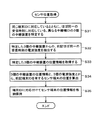
次に、以上説明したセンサ端末2の制御部20での、間欠送信開始指示の送出制御の処理動作を、図6のフローチャートを参照しながら説明する。
[Description of processing operation in sensor terminal 2]
Next, the processing operation of the transmission control of the intermittent transmission start instruction in the
すなわち、制御部20は、センサ端末2に接続されているセンサ毎の間欠送信の周期を監視する(ステップS1)。そして、制御部20は、間欠送信開始指示タイミングとなったセンサがあるか否か判別する(ステップS2)。このステップS2で、間欠送信開始指示タイミングとなったセンサがあると判別したときには、制御部20は、いずれかのセンサからのセンシングデータの取り込み中であるか否か判別する(ステップS3)。
That is, the
このステップS3で、いずれかのセンサからのセンシングデータの取り込み中ではないと判別したときには、制御部20は、間欠送信開始指示を、送信を行わせるセンサの種別の情報と共に、無線送信部24に伝達する(ステップS4)。制御部20は、ステップS4の次には、処理をステップS1に戻し、このステップS1以降の処理を繰り返す。
When it is determined in step S3 that the sensing data from any of the sensors is not being captured, the
また、ステップS3で、いずれかのセンサからのセンシングデータの取り込み中であると判別したときには、制御部20は、待機して(ステップS5)、そのセンサからのセンシングデータの取り込み終了を待つ(ステップS6)。そして、ステップS6で、センサからのセンシングデータの取り込み終了を判別したら、制御部20は、ステップS4に進み、間欠送信開始指示を、送信を行わせるセンサのセンシングデータ及び当該センサの種別の情報と共に、無線送信部24に伝達する。
If it is determined in step S3 that sensing data from any one of the sensors is being acquired, the
ステップS2で、間欠送信開始指示タイミングとなったセンサはないと判別したときには、制御部20は、イベント発生条件に合致するイベントの発生を検知したか否か判別する(ステップS7)。このステップS7で、イベント発生条件に合致するイベントの発生は検知していないと判別したときには、制御部20は、処理をステップS1に戻し、このステップS1以降の処理を繰り返す。
When it is determined in step S2 that no sensor has reached the intermittent transmission start instruction timing, the
また、ステップS7で、イベント発生条件に合致するイベントの発生を検知したと判別したときには、制御部20は、発生したイベントに関連して登録されている種別のセンサについての送信をするようにするために、間欠送信開始指示を、送信を行わせるセンサのセンシングデータ及び当該センサの種別の情報と共に、無線送信部24に伝達する(ステップS8)。そして、制御部20は、その送信を行わせたセンサについての間欠送信の周期を、より短い周期に変更する(ステップS9)。そして、制御部20は、処理をステップS1に戻し、このステップS1以降の処理を繰り返す。
Further, when it is determined in step S7 that the occurrence of an event that matches the event occurrence condition is detected, the
次に、無線送信部23での処理動作について、図7のフローチャートを参照して説明する。なお、無線送信部23が、マイクロプロセッサで構成される場合には、この図7のフローチャートの各ステップの処理は、そのマイクロプロセッサがソフトウエア処理として実行する機能に対応する。
Next, the processing operation in the
無線送信部23の間欠送信開始タイミング制御部241は、制御部20から間欠送信開始指示を受信したか否か判別し(ステップS11)、受信してはいないと判別したときには、その受信を待ち、受信したと判別したときには、乱数発生器242からの乱数値を参照して、間欠送信開始タイミングを設定する(ステップS12)。
The intermittent transmission start
無線送信部23の変調部243は、自端末の端末IDと、制御部20から通知されたセンサ種別に応じたセンサIDと、制御部20から送られてくるセンシングデータとから、図4(A)に示した送信データDAを生成する(ステップS13)。
The
そして、変調部243は、拡散符号決定部2431と315MHzFSK処理部2432とにおいて、前述した多値FSKとCCKとを組み合わせた変調方式による変調処理を行って、ステップS13で生成した送信データDAから無線送信信号の周波数を決定し、ステップS12で設定された間欠送信開始タイミング時点から、315MHz帯において、無線送信を実行する(ステップS14)。
Then, the
また、変調部243は、拡散符号決定部2431と920MHzFSK処理部2433とにおいて、前述した多値FSKとCCKとを組み合わせた変調方式による変調処理を行って、ステップS13で生成した送信データDAから無線送信信号の周波数を決定し、ステップS13における315MHz帯での無線送信の終了後(間欠送信開始タイミング時点から1ミリ秒経過後)、920MHz帯において、無線送信を実行する(ステップS15)。
In addition, the
このステップS15での920MHz帯における無線送信の終了後、処理はステップS11に戻り、このステップS11以降の処理が繰り返される。 After the end of wireless transmission in the 920 MHz band in step S15, the process returns to step S11, and the processes after step S11 are repeated.
なお、上述の説明では、センサ端末2は、間欠送信の開始から初めの1ミリ秒の間は315MHz帯の周波数を用いた無線送信を行い、その後の1ミリ秒の間に920MHz帯の周波数を用いた無線送信を行ったが、その順序は、逆であっても良い。また、乱数発生器242の乱数値に応じて、315MHz帯と920MHz帯との無線送信の順序を定めるようにしても良い。例えば乱数値が奇数であるときには、315MHz帯で先に無線送信を実行し、乱数値が偶数であるときには、920MHz帯で先に無線送信を実行するようにしても良い。
In the above description, the
次に、図2の説明に戻るが、センサ端末2は、自立電源25により駆動される。この自立電源25は、電池(バッテリー)や、電流配線の誘導起電力を利用したものを用いても良いが、この実施形態では、蛍光灯などの室内照明光によっても発電可能な太陽電池(ソーラーパネル)を用いている。そして、この自立電源25から制御部20や無線送信部24などの各部に電源電圧を供給している。
Next, returning to the description of FIG. 2, the
そして、この実施形態では、センサ端末2は、自立電源25の蓄電量(電池残量)を検出する電圧検出部26を備え、この電圧検出部26で、常時、自立電源25の蓄電量を監視して、その監視結果の蓄電量の情報を制御部20に供給するようにしている。
In this embodiment, the
この実施形態では、制御部20は、この電圧検出部26からの自立電源25の蓄電量の情報を参照し、自立電源の蓄電量が少なくなったときには、センシングデータの間欠送信の周期を長くするなどの制御を行うようにしている。また、制御部20は、適宜のタイミングで、センシングデータに代えて、自立電源25の蓄電量の情報を、自立電源25の電源状況情報として、監視センタ装置5に無線送信する。このときのデータフォーマットは、図4(A)に示したセンシングデータを送信する送信データDAと全く同様とされる。ただし、自立電源25の電源状況情報を無線送信する場合の送信データDAのセンサIDが、前述したように、センサ種別としては使用されていない3ビットの符号パターンとされ、中継装置3で、センシングデータと区別可能とされている。
In this embodiment, the
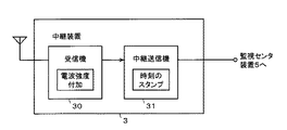
[中継装置3の説明]
中継装置3は、図8に示すように、受信機30と、中継送信機31とからなる。受信機30は、センサ端末2からの無線送信信号を受信して復調して、一旦、デジタルデータに戻す。また、受信機30は、センサ端末2から受信した無線送信信号の電波強度を検出する。そして、受信機30は、その検出した電波強度の情報をデジタルデータに変換し、復調したデジタルデータに付加して、中継送信機31に転送する。付加された電波強度の情報は、後述するように、監視センタ装置5において、センサ端末2の監視エリア1内における配置位置を算出するために用いられる。
[Description of Relay Device 3]
As shown in FIG. 8, the
中継送信機31は、受信機30からの転送データに、さらに、中継装置の識別情報(中継機ID)と、受信時刻のデータを付加して、通信網4を通じて監視センタ装置5に送信する。付加された受信時刻のデータは、監視センタ装置5において、センサ端末2からの送信データに含まれるセンシングデータの取得時刻のデータとして用いられる。
The
図9に、受信機30の構成例を示すブロック図を示す。この図9に示すように、受信機30は、315MHz帯受信処理部310と、920MHz帯受信処理部320と、ベースバンド回路からなる中継データ生成部301と、電源状況情報記憶部302とを備える。
FIG. 9 is a block diagram illustrating a configuration example of the
315MHz帯受信処理部310は、受信アンテナ310ATで受信した315MHz帯の周波数信号を受信する受信回路311と、この受信回路311で受信した周波数信号から送信データDAを復調する復調回路312と、受信回路311で受信した受信信号の電波強度を検出する電波強度検出回路313とを備える。復調回路312で、復調されたデータDMaは、中継データ生成部301に供給される。また、電波強度検出回路313で検出された電波強度Eaも、中継データ生成部301に供給される。
The 315 MHz band
また、920MHz帯受信処理部320は、受信アンテナ320ATで受信した920MHz帯の周波数信号を受信する受信回路321と、この受信回路321で受信した周波数信号から送信データDAを復調する復調回路322と、受信回路321で受信した受信信号の電波強度を検出する電波強度検出回路323とを備える。復調回路322で、復調されたデータDMbは、中継データ生成部301に供給される。また、電波強度検出回路323で検出された電波強度Ebも、中継データ生成部301に供給される。
The 920 MHz band
中継データ生成部301は、電波強度検出回路312からの電波強度Eaと、電波強度検出回路322からの電波強度Ebとを比較する。そして、復調されたデータDMaと、復調されたデータDMbとのうち、電波強度が大きい方を、監視センタ装置5に送信する復調データとして選択する。そして、その復調データに、大きい方の電波強度を付加して、中継データを生成し、中継送信機31に転送する。
The relay
また、中継データ生成部301は、復調されたデータDMaまたはDMbのセンサIDが電源状況情報の識別情報であるときには、センシングデータの代わりに、電源状況情報が含まれているので、そのときには、中継送信機31には転送せずに、受信した電源状況情報を、その受信データの端末IDに対応付けて、電源状況情報記憶部302に一時記憶する。電源状況情報記憶部302の各端末IDに対応付けられて記憶されている電源状況情報は、新たな電源状況情報が受信される毎に、その新たな情報に更新される。そして、次に、同じ端末IDの復調されたデータDMaまたはDMbを得たときに、その中継データ中に、電源状況情報記憶部302に記憶されている電源状況情報を含めて、監視センタ装置5に送るようにする。
In addition, when the sensor ID of the demodulated data DMa or DMb is the identification information of the power supply status information, the relay
この受信機30から中継送信機31に転送するデータのデータフォーマットを、図10(A)に示す。この図10(A)において、白抜きで示されている端末ID、センサID及びセンシングデータは、受信して復調されたデータDMaまたはDMbに含まれていたデータである。
The data format of the data transferred from the
そして、影線を付したデータサイズ、フラグ情報、電波強度、電源状況は、中継データ生成部301で付加されたデータである。データサイズは、中継データの全体のデータサイズを示す情報であり、また、フラグ情報は、電波強度の情報と、電源状況情報が付加されていることを示すフラグを含む。
The data size, the flag information, the radio wave intensity, and the power supply status with shadow lines are data added by the relay
次に、315MHz帯受信処理部310及び920MHz帯受信処理部320の、より詳細な構成及び動作について説明する。これら315MHz帯受信処理部310及び920MHz帯受信処理部320の構成及び動作は、取り扱う周波数帯が異なるのと、多値FSKとCCKとの組合せの変調方式における周波数の数や拡散符号等が前述したように異なるのに対応する部分を除き、同様であるので、以下の説明は、315MHz帯受信処理部310の場合を例にとる。
Next, more detailed configurations and operations of the 315 MHz band
図11は、315MHz帯受信処理部310の構成例を示すブロックである。この例では、受信回路311は、ローノイズアンプ331と、バンドパスフィルタ332と、ミキサ回路333と、局部発振器334と、ローパスフィルタ335とを備える。
FIG. 11 is a block diagram illustrating a configuration example of the 315 MHz band
受信アンテナATにて受信された信号は、ローノイズアンプ331を通じてバンドパスフィルタ332に供給されて、受信信号から315MHz帯の信号が抽出される。なお、ローノイズアンプ331からの信号は、電波強度検出回路313にも供給されている。
A signal received by the receiving antenna AT is supplied to the
バンドパスフィルタ332からの315MHz帯の信号は、ミキサ回路333に供給される。この例では、局部発振器334からの局部発振周波数は、前述した315MHz帯の256通りの割り当て周波数の最小の周波数である310.00MHzとされている。ミキサ回路333では、バンドパスフィルタ332からの315MHz帯の信号が、局部発振器334からの局部発振周波数の信号と混合されて周波数変換される。そして、ミキサ回路333の出力信号がローパスフィルタ335に供給されて帯域制限され、このローパスフィルタ335から中間周波数信号が取り出される。
The 315 MHz band signal from the
ローパスフィルタ335から得られる中間周波数信号は、バンドパスフィルタ332からの315MHz帯の信号の周波数と、局部発振器334からの局部発振周波数との差の周波数の信号である。したがって、前述した多値FSKで用いられる315MHz帯の256通りの信号は、0Hz(直流)〜12.80MHzの周波数内の256通りの周波数の中間周波数信号に変換されて、ローパスフィルタ335から得られる。このローパスフィルタ335の中間周波数信号は、復調回路312に供給される。
The intermediate frequency signal obtained from the
復調回路312は、この例ではA/D(Analog-to-Digital)変換器341と、FFT(Fast Fourier Transform)回路342と、相関演算回路343と、データ復元回路344と、拡散符号メモリ345と、相関サーチ制御部346とを備える。
In this example, the
A/D変換器341は、ローパスフィルタ335からの中間周波数信号を所定のサンプリング周波数でサンプリングし、そのサンプリング値をデジタル信号に変換する。このA/D変換器341からのデジタル信号は、FFT回路342に供給されて、時間軸データから周波数軸のデータに変換される。
The A /
この場合に、FFT回路342は、そのFFT処理の1周期においては、サンプリング周波数により定まる時間間隔ΔtでA/D変換器から到来する256個のデジタル信号を用いてFFT演算を行う。したがって、FFT回路342からは、
周波数fn=310MHz+n×1/Δt(Hz) (ただし、n=0〜255)
毎の強度レベルのデータ(時系列スペクトル)が得られる。この場合、1/Δt(Hz)=0.05MHzとなるように、サンプリング周波数は定められている。
In this case, the
Frequency fn = 310 MHz + n × 1 / Δt (Hz) (where n = 0 to 255)
Data of each intensity level (time series spectrum) is obtained. In this case, the sampling frequency is determined so that 1 / Δt (Hz) = 0.05 MHz.
したがって、FFT回路342からは、各FFT処理の1周期毎に、周波数が310.00MHz〜322.80MHzまでの間の0.05MHz間隔の256通りの周波数の信号についての強度レベルが得られる。そして、FFT回路342から各FFT処理の1周期毎に出力される256個の強度レベルのデータのうちのn(n=0〜255)番目の強度レベルのデータは、周波数fnの信号の強度レベルのデータとなっており、それぞれいずれの周波数の強度レベルのデータであるかが既知となっている。このFFT回路342からの時系列スペクトルは、相関演算回路343に供給される。
Therefore, the
この場合に、FFT回路331でのFFT処理の周期は、拡散符号速度の2以上の整数分の1とされる。すなわち、FFT回路342でのFFT処理は、拡散符号の1チップ周期内において、複数回、行われるように構成されている。そして、A/D変換器341におけるサンプリング周波数は、FFT処理の周期に同期すると共に、拡散符号の1チップの周期内において、256個のサンプリング値を、複数回得ることができるような周波数とされる。また、相関演算回路343における処理クロックも、FFT処理の周期に同期するようにされており、相関演算回路343では、いずれの周波数の受信信号についての強度レベルのデータについても相関演算を行っているかを、常に、把握することができるように構成されている。
In this case, the cycle of the FFT processing in the
拡散符号メモリ345は、前述した4チップの拡散符号の符号列パターン[1000]、[0001]、[0010]、[0100]を記憶している。相関サーチ制御部346は、拡散符号メモリ345に制御信号を送り、この拡散符号メモリから前述の4チップの4種類の拡散符号の符号列パターンを、サイクリックに読み出すように制御する。この拡散符号メモリ345から読み出された拡散符号の符号列パターンは、相関演算回路343に供給される。
The spreading
相関演算回路343では、FFT回路342からの周波数fn毎の強度レベルのデータについて、拡散符号メモリ345からの拡散符号との相関演算を行い、その相関結果の相関係数をデータ復元回路344に供給する。データ復元回路344には、相関サーチ制御部346から、拡散符号メモリ345から当該時点で読み出している4チップの拡散符号が、4種類の拡散符号のいずれであるかの拡散符号識別情報SPidが供給される。データ復元回路344は、相関演算回路343からの周波数fn毎の相関演算結果と、相関サーチ制御部346からの拡散符号識別情報SPidとから、センサ端末2から送信されたデータを復元する。
The
例えば受信信号が、前述の図4(B)の符号列がその前半の18ビットの符号列である送信データの変調出力信号であった場合を例にとって、相関演算およびデータ復元の処理について、更に説明する。 For example, in the case where the received signal is a modulated output signal of transmission data in which the code sequence in FIG. 4B is the first 18-bit code sequence, the correlation calculation and data restoration processing will be further described. explain.
この場合に、相関演算回路343は、FFT回路342からの周波数fn毎の強度レベルのデータについて、予め定めた所定の閾値レベルと比較し、強度レベルが、閾値レベルよりも大きいときには「1」、小さいときには「−1」とし、一方、拡散符号メモリ345から供給される拡散符号のチップの符号値が「0」に対して「−1」を割り当て、チップの符号値「1」に対して「1」を割り当てて、両者を掛け算することにより相関演算を行う。
In this case, the
図12(A)に示すように、この例の場合の受信信号は、4チップの拡散符号[0001]に応じて、周波数fa→周波数fa→周波数fa→周波数fbと変化する周波数信号となる。したがって、FFT回路342の出力としての時系列スペクトルは、周波数faの各区間では、図12(B)に示すように、周波数faの強度レベルが大レベルを示すものとなり、また、周波数fbの区間では、図12(C)に示すように、周波数fbの強度レベルが大レベルを示すものとなる。
As shown in FIG. 12A, the received signal in this example is a frequency signal that changes from frequency fa → frequency fa → frequency fa → frequency fb in accordance with the 4-chip spreading code [0001]. Therefore, the time-series spectrum as the output of the
前述したように、相関演算回路343では、図13(A)に示すような4チップの拡散符号[0001]の受信信号に応じた周波数faの強度レベルは、図13(B)に示すように、相関係数を演算するための値[111−1]に変換され、拡散符号メモリ345から4チップの拡散符号[0001]が供給されたときに、拡散符号[0001]の各チップの符号値は、相関係数を演算するための値[−1−1−11]とされることから、両者の相関係数は、
1×(−1)+1×(−1)+1×(−1)+(−1)×1=−4
として算出される。すなわち、このときの相関係数は有意な値を示す。
As described above, in the
1 × (−1) + 1 × (−1) + 1 × (−1) + (− 1) × 1 = −4
Is calculated as That is, the correlation coefficient at this time shows a significant value.
また、相関演算回路343では、4チップの拡散符号[0001]の受信信号に応じた周波数fbの強度レベルは、図13(C)に示すように、相関係数を演算するための値[−1−1−11]に変換され、拡散符号メモリ345から4チップの拡散符号[0001]が供給されたときに、両者の相関係数は、
(−1)×(−1)+(−1)×(−1)+(−1)×(−1)+1×1=4
として算出される。すなわち、このときの相関係数も有意な値を示す。
In the
(−1) × (−1) + (− 1) × (−1) + (− 1) × (−1) + 1 × 1 = 4
Is calculated as That is, the correlation coefficient at this time also shows a significant value.
なお、この例の場合に、周波数fa及びfbの強度レベルと、拡散符号メモリ345から相関演算回路343に供給される4チップの拡散符号が、[0001]以外の符号列であるときの相関係数は、すべて0となる。そして、以上のようにして、相関演算回路343で算出された相関係数は、データ復元回路344に供給される。
In this example, the correlation between the intensity levels of the frequencies fa and fb and the 4-chip spread code supplied from the
データ復元回路344は、図14に示すように、拡散符号の4チップの4種の符号列パターンのそれぞれの拡散符号識別情報SPidと、復元データの2ビットのデータとの対応テーブルを備える。また、データ復元回路344は、図14に示すように、拡散符号のチップの符号値「0」に割り付けられた周波数、及び拡散符号のチップの符号値「1」に割り付けられた周波数の組みと、復元データの先頭の2ビットに続く16ビットのデータの符号列パターンのそれぞれとの対応テーブルを記憶している。
As shown in FIG. 14, the
データ復元回路344は、相関演算回路343からの相関係数が有意な値であるときの相関サーチ制御部346からの拡散符号識別情報SPidから、当該相関係数が有意な値であるときの拡散符号の4チップの符号列パターンが、4種の符号列パターンのいずれであるかを認識し、上述した対応テーブルを用いて、その認識した符号列パターンに対応する2ビットのデータを、18ビットの復元データの先頭の2ビットと決定する。
The
また、データ復元回路344では、相関演算回路343からの相関係数の値と、それが有意であることを示す2つの周波数から、上述した対応テーブルを用いて、復元データの先頭の2ビットに続く16ビットのデータの符号列パターンを決定する。上述の例では、相関演算回路343は、周波数faのときの相関係数−4と、周波数fbのときの相関係数4とから、4チップの拡散符号の符号値[0]に対応する周波数は周波数fa=315.00MHz、符号値[1]に対応する周波数は周波数fb=317.15MHzであると認識し、これらに対応する16ビットの符号列[0100011010010011]を復元する。
Further, the
上述したように、復調回路312のFFT処理の周期は、拡散符号のチップ周期の整数分の1とされ、1チップ当たりについて、複数回のFFT処理がなされる。したがって、中継装置3の受信機30では、センサ端末2から送信されたデータを、そのFFT処理の複数回のうちの少なくとも1回において復調して復元することが可能である。このため、上述のように、センサ端末2から送信と、中継装置3での受信が非同期であっても、センサ端末2からの送信データを、中継装置3で受信して復元することが可能である。
As described above, the period of the FFT process of the
以上のようにして、315MHz帯受信処理部310の復調回路312で、18ビットのデータが復元され、続く18ビットについても同様にして復元されることで、36ビットの送信データDAが復元される。また、920MHz帯受信処理部320の復調回路322においても、ほぼ同様にして、復調回路322で送信データDAが復元される。
As described above, the
そして、前述したように、中継データ生成部301で、315MHz帯受信処理部310で復元されたデータと、920MHz帯受信処理部320で復元されたデータのうち、電波強度の大きい方のデータが選択されて、図10(A)に示すように、電波強度と、電源状況の情報が付加されて、中継送信機31に転送される。
Then, as described above, the relay
そして、中継送信機31では、図10(B)に示すように、受信機30からの転送信号に、当該中継装置3の識別情報である中継機IDと、センサ端末2からの送信信号の当該中継装置3での受信時刻の情報とを付加する。なお、このとき、中継送信機3は、データサイズの情報と、フラグ情報の変更処理も行う。フラグ情報には、中継機IDと受信時刻の情報のフラグが、既に付加されている電波強度情報のフラグと電源状況情報のフラグに加えて、更に追加される。
Then, in the
なお、上述の実施形態では、中継装置3は、315MHz帯の受信情報の復元データと、920MHz帯の受信情報の復元データのいずれか一方を、監視センタ装置5に送るようにしたが、両方を、そのそれぞれの電波強度の情報と共に、監視センタ装置5に送るようにしても良い。また、315MHz帯の受信情報の復元データと、920MHz帯の受信情報の復元データが一致したときにのみ監視センタ装置5に送り、違っているときには、監視センタ装置5には送らないようにしても良い。
In the above-described embodiment, the
[監視センタ装置5の説明]
図15は、監視センタ装置5のハードウエア構成例を示すブロック図である。この監視センタ装置5は、パーソナルコンピュータを用いた構成とすることができる。すなわち、図15に示すように、監視センタ装置5は、CPU(Central Processing Unit)により構成される制御部501に対して、システムバス500を通じて、通信インターフェース502、ディスプレイインターフェース503、センシングデータ蓄積部504、センサ位置取得部505、中継装置位置記憶部506、見える化情報生成部507、のそれぞれが接続されて構成されている。
[Description of Monitoring Center Device 5]
FIG. 15 is a block diagram illustrating a hardware configuration example of the
制御部501は、監視センタ装置5の全体の制御を行う。通信インターフェース502は、通信網4を通じて情報信号のやり取りをするためのものである。ディスプレイインターフェース503には、例えばLCD(Liquid Crystal Display;液晶ディスプレイ)などからなるディスプレイ508が接続される。ディスプレイインターフェース503は、ディスプレイへの表示データを供給する。
The
センシングデータ蓄積部504は、中継装置3から通信網4を通じて受信したデータに含まれるセンサのセンシングデータを、センサ端末の端末IDと、センサ種別IDと、受信時刻の情報とに対応付けて、図示を省略するメモリに蓄積する。
The sensing
センサ位置取得部505は、中継装置3から通信網4を通じて受信したデータに含まれるセンサ端末の端末IDに対応する電波強度の情報と、中継装置位置記憶部506に記憶されている各中継装置3の位置情報とから、当該端末IDのセンサ端末の監視エリア1内の位置を算出して、図示を省略するメモリに保持する。
The sensor
中継装置位置記憶部506は、監視エリア1内に配設された中継装置3の位置情報を、予め登録して記憶する。この場合に、中継装置3の位置情報は、緯度、経度に加え、高さの情報が含まれている。
The relay device
中継装置3の位置情報は、例えば中継装置3を工事者が設置したときに、その工事者がGPS測位装置などの位置測位装置を用いて測位して取得し、監視センタ装置5に送って、中継装置位置記憶部506に記憶させるようにすることができる。また、中継装置3に、GPS測位装置などの位置測位装置を用意しておき、その位置測位装置で測位した位置情報を、中継装置3から通信網4を通じて監視センタ装置5に送って、中継装置位置記憶部506に記憶させるようにしても良い。
The position information of the
見える化情報生成部507は、センシングデータ蓄積部504に蓄積されたデータに基づいて、センサ種別に応じた監視エリア1内の環境要素についての見える化情報を生成し、生成した見える化情報を、ディスプレイインターフェース503を通じて、ディスプレイ508の表示画面に可視化表示するようにする。
The visualization
なお、この図15の監視センタ装置5のハードウエア構成例において、センシングデータ蓄積部504、センサ位置取得部505及び見える化情報生成部507の処理機能は、制御部501が、対応するプログラムを実行することによりソフトウエア処理機能として構成することができる。
In the hardware configuration example of the
以下に、監視センタ装置5における処理動作について説明する。以下の説明においては、制御部501が、センシングデータ蓄積部504の処理機能を、ソフトウエア処理機能として構成した場合として説明する。
Hereinafter, description about the processing operation in the
制御部501は、受信したデータから抽出した端末IDと受信時刻の情報と電源状況情報とを対応付けて、メモリに蓄積する。
A
また、制御部501は、中継装置3から受信したデータから抽出した端末IDと、中継器IDと、センサIDと、受信時刻の情報と、センシングデータと、電波強度の情報と、対応付けて蓄積する。なお、中継装置3が、電源状況を示すセンサIDを含むセンサ端末からの送信信号も監視センタ装置5に送る場合には、監視センタ装置5の制御部501は、図16のフローチャートのステップS21〜ステップS23に示すような処理をするものである。
Also,
端末IDと受信時刻と対応付けられて蓄積された電源状況情報は、監視センタ装置5で、センサ端末の自立電源の蓄電量の監視に用いられる。
The power supply status information stored in association with the terminal ID and the reception time is used by the
また、端末ID、中継機ID、センサID及び受信時刻の情報と対応付けられて蓄積された電波強度の情報は、センサ端末位置取得部505でのセンサ端末の位置の算出処理に用いられる。
Further, the information on the radio wave intensity accumulated in association with the information on the terminal ID, the relay ID, the sensor ID, and the reception time is used in the sensor terminal
図17に、センサ端末位置取得部505でのセンサ端末の位置の算出処理動作の例を示すフローチャートを示す。この図17の例の説明も、制御部501が、センサ端末位置取得部505の処理機能を、ソフトウエア処理機能として構成した場合として説明する。
FIG. 17 is a flowchart illustrating an example of the sensor terminal position calculation processing operation in the sensor terminal
制御部501は、例えば一定周期で、あるいは、適宜のセンサ端末位置の再取得のタイミング時点において、図17の処理ルーチンを開始させる。ここで、センサ端末位置の再取得のタイミング時点は、例えば管理者等から、監視エリア1内でセンサ端末2の位置が変更されたことの通知を監視センタ装置5で受けたときなどとしても良い。
For example, the
そして、制御部501は、センシングデータ蓄積部504のメモリに格納されているデータから、同じ端末IDに対応付けられているとともに、ほぼ同一の時刻と見なせる最新の受信時刻に対応して記憶されている、中継機IDが異なる3個の中継装置3を特定する(ステップS31)。次に、制御部501は、その判定した3個の中継装置3からの前記受信時刻の電波強度を抽出する(ステップS32)。
The
次に、制御部501は、ステップS31で判定した3個の中継装置の位置情報を、それぞれの中継機IDを用いて、中継装置位置記憶部506から取得する(ステップS33)。そして、制御部501は、取得した3個の中継装置の位置情報と、3個の電波強度の情報とから、ステップS31で中継装置3を特定する際に用いた端末IDを有するセンサ端末2の監視エリア1内の位置を算出する(ステップS34)。すなわち、電波強度は、センサ端末2と中継装置3との距離に応じたものとなっているので、既知の3個の中継装置の位置情報と、距離に対応した電波強度を用いて、いわゆる3点測位の方法で、センサ端末2の位置を算出する。
Next, the
そして、制御部501は、算出したセンサ端末の位置情報を、その端末IDに対応付けて、メモリに格納保持する(ステップS35)。この場合に、メモリには、同じ端末IDと共に送られてくるセンサIDも、対応付けられて記憶される。これにより、同じ端末IDに接続されているセンサIDが異なる複数個のセンサは、同じ位置情報を持つ(同じ位置に存在する)ことになるが、センサIDが同じである複数のセンサのそれぞれについては、異なる位置情報を持つ(異なる位置に存在する)ことが記憶される。以上で、この処理ルーチンは終了である。
Then, the
この図17の処理ルーチンにより、センサ端末2の位置が、監視エリア1内で移動されたとしても、監視センタ装置5では、自動的にその移動位置を算出して、当該センサ端末2の位置を常に把握して保持することができる。
Even if the position of the
見える化情報生成部507は、センシングデータ蓄積部504のメモリに蓄積されたデータと、センサ端末位置取得部505のメモリに記憶された位置情報とを用いることで、見える化情報を生成する。
The visualization
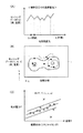
図18は、見える化情報生成部507で生成される見える化情報の例を示す図である。見える化情報の第1の例は、特定の位置における特定の種類のセンサのセンシングデータの時系列変化を見える化情報として生成して、ディスプレイに表示するものである。図18(A)は、その一例で、赤外線アレーセンサ61による監視エリア1内のユーザにより指定された特定の位置における温度の時系列変化を示している。図18(A)の例では、特定の位置は、「場所○○」として表示される。
FIG. 18 is a diagram illustrating an example of visualization information generated by the visualization
この第1の例の場合には、見える化情報生成部507は、センシングデータ蓄積部504のメモリに記憶されているデータから、ユーザにより指定された見える化の環境要素に対応するセンサ種別のセンサについて、指定された位置に対応して受信時刻順に記憶されているセンシングデータを抽出して読み出し、その読み出したデータを用いて、図18(A)に示すような時系列表示の表示情報を生成し、ディスプレイ508の表示画面に表示する。
In the case of this first example, the visualization
見える化情報の第2の例は、監視エリア1内に多数配置されている特定の種類のセンサによるセンシングデータを用いて、当該センサで検知される環境要素の監視エリア1内での空間分布(監視エリア1内の環境状況)を見える化表示する例である。図18(B)は、その一例で、監視エリア1内の各所に分散されて複数配置された赤外線アレーセンサ61のそれぞれからの特定の時点におけるセンシングデータを用いて、当該時点における監視エリア1内の各所の温度を見える化処理して、表示した例である。図18(B)において黒丸の点は、センサ位置(そのセンサが接続されているセンサ端末の位置)を示し、黒丸の点を結んだ線は、同一温度とされる位置を結んで示した線(等温線)である。これにより、監視エリア1内における位置の違いに応じた温度環境を詳細に表示して見える化することができる。
A second example of the visualization information is a spatial distribution (in the monitoring area 1) of environmental elements detected by the sensor using sensing data from a specific type of sensor arranged in large numbers in the
この例の場合には、見える化情報生成部507は、センシングデータ蓄積部504のメモリに記憶されているデータから、ユーザにより指定された見える化の環境要素に対応するセンサ種別の全てのセンサについて、指定された時点におけるセンシングデータを抽出して読み出すと共に、それぞれのセンサ接続されているセンサ端末の位置を、センサ端末位置記憶部505のメモリから読み出す。そして、見える化情報生成部507は、監視エリア1内を座標空間として、各センサの位置に対応して、センシングデータとしての温度情報を配置し、同一温度の位置を線で結ぶことで、図18(B)に示すような見える化情報を生成する。
In the case of this example, the visualization
なお、空間分布を表示する時点を、順次に変えて表示するようにすることで、空間分布の時系列変化も表示して見える化することができることは言うまでもない。 It goes without saying that the time series of the spatial distribution can be displayed and visualized by sequentially changing and displaying the time points when the spatial distribution is displayed.
見える化情報の第3の例は、監視エリア1内で監視する環境要素同士の相関を見える化処理して表示する例である。図18(C)は一例で、電流・磁界センサ65のセンシングデータから算出された使用電力Pと、赤外線アレーセンサ61のセンシングデータである温度Tとの相関分布を見える化処理して表示した例である。
The third example of visualization information is an example in which the correlation between environmental elements monitored in the
この例の場合には、見える化情報生成部507は、センシングデータ蓄積部505に蓄積されている全ての電流・磁界センサ65のセンシングデータと、全ての赤外線アレーセンサ61のセンシングデータを抽出して、受信時刻を対応情報として対応付けながら、両者の相関を求め、その結果を相関分布として、図18(C)に示すような表示情報を生成して、ディスプレイ508の表示画面に表示する。
In this example, the visualization
なお、見える化処理の第2の例の空間分布の他の表示例を図19及び図20に示す。図19は、監視エリア1が工場であって、複数の装置が監視エリア1内である工場内に配設されている場合において、特定の時点における塵埃センサ62によるセンシングデータを用いた塵埃濃度の空間分布の示すものである。図19に表示されている線は、塵埃濃度が等しい位置を結んだ線であり、細い線は塵埃濃度が低く、線が太くなるほど塵埃濃度が高くなることを示している。
Other display examples of the spatial distribution of the second example of the visualization process are shown in FIGS. FIG. 19 shows the case of the dust concentration using the sensing data by the
この図19の塵埃濃度の空間分布も、表示すべき時系列上の時点を変えることで、この塵埃濃度の空間分布が変化する態様を見える化することもできる。その場合には、この図19の例の塵埃濃度分布の表示例を観視することにより、設備の大きさ、高さ、その他の要因により、塵埃濃度が時間的、空間的に変動が生じることを容易に把握することができる。 The spatial distribution of the dust concentration in FIG. 19 can also be visualized by changing the time point on the time series to be displayed. In that case, by watching the display example of the dust concentration distribution in the example of FIG. 19, the dust concentration varies temporally and spatially due to the size, height, and other factors of the equipment. Can be easily grasped.
また、図20は、監視エリア1がオフィス空間の場合であって、気流の強度分布を表示した例である。この図20の例では、見える化情報生成部507では、監視エリア1について、窓や扉の位置を対応付けて表示するようにしている。これにより、より気流の強度分布と環境との関係を把握することができる。
FIG. 20 is an example in which the
[他の実施形態]
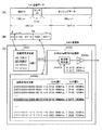
上述の実施形態では、中継装置31〜3mの各々が、監視センタ装置5と通信網4を通じて接続されて、中継データを生成して、監視センタ装置5に転送するようにした。しかし、図21に示すように、監視センタ装置5と通信網4を通じて接続されるのは、複数個の中継装置3のうちの特定の1個とするように構成しても良い。
[Other Embodiments]
In the above-described embodiment, each of the
図21の例では、中継装置33のみが通信網4を通じて監視センタ装置5と接続されている。そして、この中継装置33以外の中継装置31、32は、この中継装置33と接続されるように構成されている。この場合の中継装置33と中継装置31、32との接続は、有線であっても良いし、センサ端末2と同様に、無線接続であっても良い。
In the example of FIG. 21, only the
この例の場合には、中継装置33から通信網4を通じて監視センタ装置5へ転送されるデータは、図10(B)に示したデータフォーマットとするが、中継装置33と中継装置31、32との間におけるデータ転送におけるデータフォーマットは、図10(A)に示すようなものとされる。ただし、中継装置31、32から中継装置33に転送されるデータには、中継装置31、32の中継機IDが含まれる。
In this example, the data to be transferred to the
なお、この図21の例の場合には、他の中継装置からの情報を受けて、監視センタ装置5に情報を転送する中継装置において、上述した監視センタ装置におけるセンサ端末2の監視エリア1内の位置検出を行って、その検出したセンサ端末2の位置情報を、監視センタ装置5に通知するようにしても良い。
In the case of the example in FIG. 21, in the relay device that receives information from other relay devices and transfers the information to the
[実施形態の効果]
上述の実施形態のセンサネットワークシステムによれば、監視エリア内に多数のセンサを配置して、その監視エリア内の位置の違いに応じた環境状況を、時系列変化を含めてセンサからのセンシングデータを見える化処理して表示することができるので、監視エリア内の詳細な環境状況の監視をすることができる。
[Effect of the embodiment]
According to the sensor network system of the above-described embodiment, a large number of sensors are arranged in the monitoring area, and the environmental situation according to the difference in position in the monitoring area is detected from the sensing data including the time series change. Can be visualized and displayed, so that detailed environmental conditions in the monitoring area can be monitored.
また、上述の実施形態においては、中継装置において、センサ端末からの受信信号について、当該受信信号の受信時点の情報を付加して監視センタ装置に送るようにして、監視センタ装置では、その中継装置で付加された時刻情報を、センサ端末からの送信信号に含まれるセンシングデータの取得時間として取り扱うようにしている。このため、センサ端末からの送信信号には、時刻情報を付加する必要はない。 In the above-described embodiment, the relay device adds the information at the time of reception of the received signal to the monitoring center device with respect to the received signal from the sensor terminal, and the monitoring center device transmits the received signal to the monitoring center device. The time information added in is handled as the acquisition time of sensing data included in the transmission signal from the sensor terminal. For this reason, it is not necessary to add time information to the transmission signal from the sensor terminal.
また、上述の実施形態では、中継装置において、センサ端末からの受信信号を受信したときの電波強度を検出し、その検出した電波強度の情報を、センサ端末からの受信信号に付加して監視センタ装置に送るようにして、監視センタ装置で、その電波強度の情報を用いて、センサ端末の監視エリア内の位置を算出するようにしている。このため、センサ端末からの送信信号には、センサ端末の位置情報を付加する必要はない。 Further, in the above-described embodiment, the relay device detects the radio field intensity when the reception signal from the sensor terminal is received, and adds the information on the detected radio field intensity to the reception signal from the sensor terminal to monitor the center. The monitoring center device calculates the position of the sensor terminal in the monitoring area by using the information on the radio field intensity. For this reason, it is not necessary to add the position information of the sensor terminal to the transmission signal from the sensor terminal.
以上のことから、上述の実施形態においては、センシングデータの取得時間の情報やセンサ端末の位置情報を有しないため、センサ端末からの送信データは、必要最小限の識別情報とセンシングデータとからなり、非常に短文となる。このため、監視エリア内の多数のセンサ端末のそれぞれから、所定の間欠周期で送信データを無線送信させるようにした場合であっても、センサ端末からの送信データの無線送信を、前記間欠周期内で分散させることが容易になり、互いに衝突することなく送信データを無線送信することが可能となる。 As described above, in the above-described embodiment, since there is no sensing data acquisition time information or sensor terminal position information, the transmission data from the sensor terminal is composed of minimum necessary identification information and sensing data. It will be very short. Therefore, even when transmission data is wirelessly transmitted from each of a large number of sensor terminals in the monitoring area at a predetermined intermittent period, wireless transmission of transmission data from the sensor terminal is performed within the intermittent period. The transmission data can be easily distributed and the transmission data can be wirelessly transmitted without colliding with each other.
そして、上述の実施形態によれば、センサ端末からの間欠送信の開始タイミングは、予め定められた所定の周期で定まるタイミングから、乱数値に応じて遅延されるようにしているので、複数のセンサ端末の間で、送信開始タイミングが衝突するのをできるだけ回避することができる。 According to the above-described embodiment, the intermittent transmission start timing from the sensor terminal is delayed according to the random number value from the timing determined in a predetermined cycle, so that the plurality of sensors It is possible to avoid collision of transmission start timings between terminals as much as possible.
また、上述の実施形態においては、センサ端末は、送信データを多値FSKとCCKとを組み合わせた変調方式により変調して無線送信するようにするので、センサ端末からの送信信号は、送信データのデータ内容に応じた周波数となり、もしも、送信開始タイミングが衝突したとしても、送信信号の周波数が同一となることが少ない。このため、受信側では、送信開始タイミングが同一である送信信号をも、分離して復調することができるようになり、送信信号の受信を失敗する確立が少なくなる。 In the above-described embodiment, the sensor terminal modulates the transmission data by a modulation scheme combining multi-level FSK and CCK and wirelessly transmits the transmission data. Therefore, the transmission signal from the sensor terminal is the transmission data. The frequency depends on the data content, and even if the transmission start timing collides, the frequency of the transmission signal is rarely the same. For this reason, on the receiving side, transmission signals having the same transmission start timing can be demodulated separately, and the probability of failure in receiving transmission signals is reduced.
さらに、上述の実施形態によれば、センサ端末からの送信信号は、315MHzと920MHzと言うように、分離が容易な互いに異なる周波数帯により、同じデータ内容を重ねて送信するようにするので、受信側では、同じデータを受信できる機会が複数回得られ、より確実に受信することができる。 Furthermore, according to the above-mentioned embodiment, since the transmission signal from the sensor terminal is transmitted in the same frequency range by using different frequency bands that are easily separated, such as 315 MHz and 920 MHz, it is received. On the side, the opportunity to receive the same data is obtained a plurality of times, and it can be received more reliably.
[その他の実施形態又は変形例]
上述の実施形態の監視センタ装置5のセンサ端末位置取得部505では、中継装置3で付加されたセンサ端末2からの送信信号を受信したときの電波強度を用いて、各センサ端末2の位置を算出して取得するようにした。しかし、監視センタ装置5のセンサ端末位置取得部505が、センサ端末2の位置を取得する方法は、これに限られるものではない。幾つかの例を挙げる。
[Other Embodiments or Modifications]
In the sensor terminal
<センサ端末位置取得部505の他の例のその1>
センサ端末位置取得部505の他の例のその1では、中継装置3は、電波強度の情報を付加することなく、センサ端末2からの送信信号は、その受信時刻の情報のみを付加して、監視センタ装置5に転送する。監視センタ装置5では、中継装置で付加されるセンサ端末からの送信信号の受信時点の情報を用いて、各センサ端末の位置を算出して取得する。すなわち、少なくとも3個の中継装置3からの転送信号のうちの、同一のセンサの識別情報を含み、同一のセンシングデータ内容の転送信号に含まれるセンシングデータの受信時点の時間差は、センサ端末2からの送信信号の受信信号の電波強度と同様に、中継装置3と、それぞれセンサ端末2との距離に応じたものとなっている。そこで、監視センタ装置5では、これらの同一のセンサの識別情報を含み、同一のセンシングデータ内容の転送信号に含まれるセンシングデータの受信時点の時間差に基づいて、前記識別情報で特定されるセンサの位置を算出して取得することができる。
<
In the first example of another example of the sensor terminal
<センサ端末位置取得部505の他の例のその2>
センサ端末位置取得部505の他の例のその2は、中継装置を用いない例である。すなわち、例えば、センサ端末のそれぞれを監視エリアに設置したときに、その設置工事作業者が、そのセンサ端末の位置を、GPS測位手段などを用いて測位して、その測位した位置情報を、センサ端末の端末IDと対応付けて記憶しておき、その記憶した位置情報を、監視センタ装置5に設けた記憶装置に転送して登録するようにする。また、測位した位置情報とセンサ端末の端末IDとの対応情報を、例えば携帯電話網を通じて、監視センタ装置に送って、前記記憶装置に位置登録するようにしても良い。監視センタ装置5のセンサ端末位置取得部505は、その記憶装置に記憶されている各センサ端末の位置情報を、受信信号に含まれる端末IDに基づき取得するようにする。
<
The other example 2 of the sensor terminal
このセンサ端末位置取得部505の他の例のその2の場合には、中継装置は不要になるが、この例においては、監視センタ装置は、自装置がセンサ端末からの送信信号を受信した時刻を、センシングデータの取得時刻の情報として用いる。
In the case of the second example of the other example of the sensor terminal
次に、上述の実施形態では、センサ端末は、間欠送信のタイミングにおいては、同じ送信信号内容を、第1の周波数帯(315MHz帯)の送信区間と、第2の周波数帯(920MHz帯)の送信区間とで、時分割で送信するようにした。しかし、複数個の周波数帯を用いて、同じ送信信号内容を送信する方法は、この例に限らない。 Next, in the above-described embodiment, the sensor terminal transmits the same transmission signal content in the transmission period of the first frequency band (315 MHz band) and the second frequency band (920 MHz band) at the timing of intermittent transmission. It was made to transmit by the time division with the transmission section. However, the method of transmitting the same transmission signal content using a plurality of frequency bands is not limited to this example.
例えば、センサ端末のそれぞれは、間欠の無線送信の度毎に、同じ送信信号を、第1の周波数帯(315MHz帯)と、第2の周波数帯(920MHz帯)とのそれぞれに割り付けて、同じ送信区間に同時に無線送信するようにしても良い。この場合、第1の周波数帯(315MHz帯)と、第2の周波数帯(920MHz帯)とは、周波数的に有意に離間しているので、受信側では、容易に周波数分離して受信処理ができる。 For example, each of the sensor terminals allocates the same transmission signal to each of the first frequency band (315 MHz band) and the second frequency band (920 MHz band) for each intermittent wireless transmission, and the same. Wireless transmission may be performed simultaneously in the transmission section. In this case, since the first frequency band (315 MHz band) and the second frequency band (920 MHz band) are significantly separated in terms of frequency, the reception side can easily perform frequency separation and receive processing. it can.
また、同じ送信信号内容を、第1の周波数帯(315MHz帯)の送信区間と、第2の周波数帯(920MHz帯)の送信区間とで、時分割で送信するように方法において、第1の周波数帯(315MHz帯)と、第2の周波数帯(920MHz帯)とを、それぞれ更に分割すると共に、第1の周波数帯(315MHz帯)の送信区間及び第2の周波数帯(920MHz帯)の送信区間のそれぞれを、分割した周波数帯の数に応じて更に分割して、その分割した送信区間のそれぞれにおいて、時分割送信するようにしても良い。 Further, in the method in which the same transmission signal content is transmitted in a time division manner in the transmission section of the first frequency band (315 MHz band) and the transmission section of the second frequency band (920 MHz band), The frequency band (315 MHz band) and the second frequency band (920 MHz band) are further divided, and the first frequency band (315 MHz band) transmission section and the second frequency band (920 MHz band) are transmitted. Each of the sections may be further divided according to the number of divided frequency bands, and time division transmission may be performed in each of the divided transmission sections.
なお、上述の実施形態では、センサ端末からの無線送信に使用する周波数は、315MHz帯や920MHz帯としたが、これは一例であり、これらの周波数に限られるものではないことは言うまでもない。 In the above-described embodiment, the frequency used for wireless transmission from the sensor terminal is the 315 MHz band or the 920 MHz band. However, this is an example, and it goes without saying that the frequency is not limited thereto.
また、上述の実施形態では、センサ端末からの無線送信に使用する周波数は、315MHz帯や920MHz帯の2つの周波数帯としたが、3個以上の周波数帯を用いて、それらの周波数帯で、センサ端末からの同じ送信信号を重ねて送信するようにしても勿論良い。 Moreover, in the above-described embodiment, the frequencies used for wireless transmission from the sensor terminal are two frequency bands of 315 MHz band and 920 MHz band, but using three or more frequency bands, in those frequency bands, Of course, the same transmission signal from the sensor terminal may be transmitted in an overlapping manner.
なお、上述の実施形態では、センサ端末のそれぞれは、受信機能を有していないために、中継装置から受信確認信号を受信することができない構成とされていたが、センサ端末に受信機能を具備させ、中継装置からの受信確認信号を受信しなかったときには、センシングデータを再送させるように構成してもよい。また、センサ端末と中継装置との間の通信は、非同期としたが、例えばセンサ端末から同期用のタイミング信号を送出した後、中継装置にセンシングデータを送信するようにして、同期通信を行うようにしても良い。 In the above-described embodiment, each of the sensor terminals does not have a reception function, and thus the reception confirmation signal cannot be received from the relay device. However, the sensor terminal has a reception function. When the reception confirmation signal from the relay apparatus is not received, the sensing data may be retransmitted. In addition, the communication between the sensor terminal and the relay device is asynchronous. For example, after sending a timing signal for synchronization from the sensor terminal, the sensing data is transmitted to the relay device so that the synchronous communication is performed. Anyway.
1…監視エリア、2(21〜2n)…センサ端末、3(31〜3m)…中継装置、4…通信網、5…監視センタ装置、24…無線送信部、242…乱数発生器、243…変調部、244…ID割付部、30…受信機、301…中継データ生成部、31…中継送信機、311,321…受信回路、312,322…復調回路、313,323…電波強度検出回路、504…センシングデータ蓄積部、505…センサ端末位置取得部、506…中継装置位置記憶部、507…見える化情報生成部
DESCRIPTION OF
Claims (15)
前記複数個のセンサ端末のそれぞれは、
前記センサ端末に接続されている前記センサのそれぞれ毎に、前記センサ端末の端末識別情報と、前記センサのセンサ種別を識別するセンサ識別情報と、前記センサの最新のセンシングデータとからなる第1の送信信号を間欠的に無線送信すると共に、
前記センサの種別に割り当てられない所定の符号パターンのセンサ識別情報を電源状況情報の識別情報として割り当て、前記センシングデータに代えて前記自立の電源の電源状況情報を含めた、前記第1の送信信号と同一のデータフォーマットの第2の送信信号を間欠的に無線送信する送信手段を有し、
前記監視センタ装置は、
前記所定のエリア内での前記複数個のセンサ端末の位置情報を取得する位置情報取得手段と、
前記複数個のセンサ端末からの前記第1の送信信号に含まれるセンシングデータのそれぞれを、前記端末識別情報と前記センサ識別情報と前記センシングデータの取得時点とを対応させて時系列データとして蓄積するセンシングデータ蓄積手段と、
前記位置情報取得手段で取得した前記センサ端末の位置情報と、前記センシングデータ蓄積手段で蓄積した前記センサ端末のそれぞれからの前記センサ識別情報に対応付けられているセンシングデータの前記時系列データとに基づいて、前記センサ識別情報で識別されるセンサ種別毎に、前記所定のエリア内における前記センサにより検出される環境要素の時系列変化を視覚化して呈示する見える化手段と、
前記複数個のセンサ端末からの前記電源状況情報のそれぞれを、前記端末識別情報及び前記電源状況情報の取得時点と対応させて、前記センサ端末毎の前記自立電源の電源状況の監視用として蓄積する電源状況情報蓄積手段と、
を備えることを特徴とするセンサネットワークシステム。 While being driven by an independent power source, a plurality of types of one or a plurality of sensors are connected, and sensor terminals that wirelessly transmit sensing data from the sensors are arranged at predetermined positions in a predetermined area. Thus, in a sensor network system comprising a plurality of sensor terminals arranged in the predetermined area and a monitoring center device that collects sensing data wirelessly transmitted from each of the plurality of sensor terminals,
Each of the plurality of sensor terminals is
For each of the sensors connected to the sensor terminal, a first identification comprising terminal identification information of the sensor terminal, sensor identification information for identifying the sensor type of the sensor, and the latest sensing data of the sensor While transmitting the transmission signal wirelessly intermittently,
The first transmission signal including sensor identification information having a predetermined code pattern that is not assigned to the sensor type, as power supply status information identification information, and including power supply status information of the independent power supply instead of the sensing data Transmission means for intermittently wirelessly transmitting a second transmission signal of the same data format as
The monitoring center device
Position information acquisition means for acquiring position information of the plurality of sensor terminals in the predetermined area;
Each of the sensing data included in the first transmission signals from the plurality of sensor terminals is stored as time series data in association with the terminal identification information, the sensor identification information, and the acquisition time of the sensing data. Sensing data storage means;
The position information of the sensor terminal acquired by the position information acquisition means and the time-series data of the sensing data associated with the sensor identification information from each of the sensor terminals stored by the sensing data storage means Visualizing means for visualizing and presenting time-series changes of environmental elements detected by the sensor in the predetermined area for each sensor type identified by the sensor identification information,
Each of the power status information from the plurality of sensor terminals is stored for monitoring the power status of the independent power source for each sensor terminal in association with the terminal identification information and the acquisition time of the power status information. Power status information storage means;
A sensor network system comprising:
前記センサ端末からの前記第1の送信信号及び前記第2の送信信号には、前記センシングデータを取得した時点の時刻情報及び前記電源状況情報を取得した時点の時刻情報を含まないことを特徴とする請求項1に記載のセンサネットワークシステム。 The monitoring center apparatus regards the reception time of the sensing data and the reception time of the power supply status information as the acquisition time of the sensing data and the acquisition time of the power supply status information in the sensor terminal, Executing the power status information storage means;
The first transmission signal and the second transmission signal from the sensor terminal, and characterized in that it does not contain the time information at the time of acquiring time information and power status information at the time of acquiring the sensing data The sensor network system according to claim 1.
前記中継装置のそれぞれは、
前記センサ識別情報に基づいて前記受信した信号が前記第1の送信信号であると判別したときに、前記受信した信号の電波強度を検出する検出手段と、
前記検出した前記電波強度の情報を、前記センサ端末から受信した前記第1の送信信号に加えた転送情報を生成して、前記監視センタ装置に転送する転送手段を備え、
前記監視センタ装置の前記位置情報取得手段は、前記少なくとも3個の中継装置からの前記転送情報のうちの、同一の端末識別情報、同一のセンサ識別情報及び同一のセンシングデータを含む転送情報に含まれる前記電波強度から、前記端末識別情報で特定されるセンサ端末の位置を算出して取得することを特徴とする請求項1〜請求項3のいずれかに記載のセンサネットワークシステム。 In the predetermined area, at least three relay devices are arranged,
Each of the relay devices
Detecting means for detecting a radio wave intensity of the received signal when the received signal is determined to be the first transmission signal based on the sensor identification information ;
Transfer means for generating transfer information added to the first transmission signal received from the sensor terminal with the detected information on the radio field intensity, and transferring the information to the monitoring center device;
The position information acquisition means of the monitoring center device is included in transfer information including the same terminal identification information, the same sensor identification information, and the same sensing data among the transfer information from the at least three relay devices. 4. The sensor network system according to claim 1, wherein the position of the sensor terminal specified by the terminal identification information is calculated and acquired from the received radio wave intensity. 5.
前記センサ識別情報に基づいて前記受信した信号が前記第2の送信信号であると判別したときに、前記端末識別情報と対応付けて前記受信した前記第2の送信信号の前記電源状況情報を記憶部に一時記憶する記憶手段を備え、
前記転送手段は、前記センサ識別情報に基づいて前記受信した信号が前記第1の送信信号であると判別したときに、前記電波強度の情報に加えて、前記第1の送信信号に含まれる前記端末識別情報に対応付けて前記記憶部に記憶されている前記電源状況情報を、前記第1の送信信号に加えた転送情報を生成して、前記監視センタ装置に転送し、
前記監視センタ装置の電源状況情報蓄積手段は、前記転送情報から前記端末識別情報と前記電源状況情報とを抽出して蓄積する
ことを特徴とする請求項4に記載のセンサネットワークシステム Each of the relay devices
When it is determined that the received signal is the second transmission signal based on the sensor identification information, the power status information of the received second transmission signal is stored in association with the terminal identification information Storage means for temporarily storing in the unit,
When the transfer means determines that the received signal is the first transmission signal based on the sensor identification information, the transfer means is included in the first transmission signal in addition to the information on the radio wave intensity. Generating transfer information in which the power status information stored in the storage unit in association with terminal identification information is added to the first transmission signal, and transferring the information to the monitoring center device;
5. The sensor network system according to claim 4 , wherein the power status information storage means of the monitoring center device extracts and stores the terminal identification information and the power status information from the transfer information.
前記センサ端末からの前記第1の送信信号の受信時点を検出する手段を備え、
前記転送手段は、前記センサ端末からの前記第1の送信信号を受信した受信時点の時刻情報を、前記監視センタ装置に転送する情報にさらに加えるようにし、
前記監視センタ装置は、前記中継装置からの前記転送情報中の前記受信時点の時刻情報を、前記センサ端末における前記センシングデータ又は前記電源状況情報の取得時点の時刻情報と見なして、前記センシングデータ蓄積手段又は電源状況情報蓄積手段を実行することを特徴とする請求項4又は請求項5に記載のセンサネットワークシステム。 Each of the relay devices
Means for detecting a reception time point of the first transmission signal from the sensor terminal;
The transfer means further adds time information at the time of reception when the first transmission signal from the sensor terminal is received to information to be transferred to the monitoring center device,
The monitoring center device regards the time information at the time of reception in the transfer information from the relay device as time information at the time of acquisition of the sensing data or the power status information in the sensor terminal, and stores the sensing data. 6. The sensor network system according to claim 4 or 5, wherein means or power status information storage means is executed.
前記中継装置のそれぞれは、
前記センサ識別情報に基づいて前記受信した信号が前記第1の送信信号であると判別したときに、前記受信した信号の受信時点を検出する検出手段と、
前記検出した前記受信時点の情報を、前記センサ端末から受信した前記第1の送信信号に加えた転送情報を生成して、前記監視センタ装置に転送する転送手段を備え、
前記監視センタ装置の前記位置情報取得手段は、前記中継装置からの前記転送情報中の前記受信時点を、前記センサ端末からの前記センシングデータの取得時点と見なして、前記センシングデータ蓄積手段を実行すると共に、前記少なくとも3個の前記中継装置からの前記転送情報のうちの、同一の端末識別情報同一のセンサ識別情報及び同一のセンシングデータを含む転送情報に含まれる前記受信時点の時間差に基づいて、前記端末識別情報で特定される前記センサ端末の位置を算出して取得することを特徴とする請求項1〜請求項3のいずれかに記載のセンサネットワークシステム。 In the predetermined area, at least three relay devices are arranged,
Each of the relay devices
Detecting means for detecting a reception time point of the received signal when the received signal is determined to be the first transmission signal based on the sensor identification information ;
Wherein the detected information before Symbol reception time, generates the transfer information is added to the first transmission signal received from the sensor terminal, comprising a transfer means for transferring the monitoring center device,
The position information acquisition unit of the monitoring center apparatus regards the reception time point in the transfer information from the relay device as an acquisition time point of the sensing data from the sensor terminal, and executes the sensing data storage unit with, based said one of said transfer information from at least three of said relay device, the time difference before Ki受 signal point included in the transfer information containing the same terminal identification information identical sensor identification information and the same sensing data Te, the sensor network system according to any one of claims 1 to 3, characterized in that obtained by calculating the position of the sensor terminal specified by the terminal identification information.
前記センサ識別情報に基づいて前記受信した信号が前記第2の送信信号であると判別したときに、前記端末識別情報と対応付けて前記受信した前記第2の送信信号の前記電源状況情報を記憶部に一時記憶する記憶手段を備え、When it is determined that the received signal is the second transmission signal based on the sensor identification information, the power status information of the received second transmission signal is stored in association with the terminal identification information Storage means for temporarily storing in the unit,
前記転送手段は、前記センサ識別情報に基づいて前記受信した信号が前記第1の送信信号であると判別したときに、前記受信時点に加えて、前記第1の送信信号に含まれる前記端末識別情報に対応付けて前記記憶部に記憶されている前記電源状況情報を、前記第1の送信信号に加えた転送情報を生成して、前記監視センタ装置に転送し、The transfer means, when determining that the received signal is the first transmission signal based on the sensor identification information, in addition to the reception time point, the terminal identification included in the first transmission signal Generating the transfer information added to the first transmission signal, the power status information stored in the storage unit in association with the information, and transferring the information to the monitoring center device,
前記監視センタ装置の電源状況情報蓄積手段は、前記転送情報から前記端末識別情報と前記電源状況情報とを抽出して蓄積するThe power status information storage means of the monitoring center device extracts and stores the terminal identification information and the power status information from the transfer information.
ことを特徴とする請求項7に記載のセンサネットワークシステム。The sensor network system according to claim 7.
前記乱数発生器から発生する乱数に基づいて、前記間欠的な無線送信の開始タイミングを決定することを特徴とする請求項1〜請求項8のいずれかに記載のセンサネットワークシステム。 Each of the sensor terminals comprises a random number generator,
9. The sensor network system according to claim 1, wherein a start timing of the intermittent wireless transmission is determined based on a random number generated from the random number generator.
前記センサ端末のそれぞれは、前記複数個のセンサのいずれかによるセンシングデータから特定のイベントが発生したか否かを監視する監視手段を備え、
前記監視手段で前記特定のイベントが発生したことを検出したときには、前記間欠的な無線送信のタイミングに関わらず、前記検出した前記イベントの発生時点で、前記イベントの発生を検出した前記センシングデータについての前記第1の送信信号と、前記イベントの発生を検出した前記センシングデータを発生するセンサ種別に関連付けられたセンサ種別のセンサからの前記センシングデータについての前記第1の送信信号を無線送信することを特徴とする請求項1〜請求項9のいずれかに記載のセンサネットワークシステム。 A plurality of types of sensors are connected to each of the sensor terminals,
Each of the sensor terminals comprises monitoring means for monitoring whether a specific event has occurred from sensing data from any of the plurality of sensors ,
Wherein when said specific event by the monitoring means detects that it has occurred, regardless of the timing before Symbol intermittent radio transmission, the at generation time of the detected the event, the sensing of the detection of the occurrence of the event said first transmission signal for data, the first transmission signal radio transmissions for the sensing data from the sensor of the sensor type associated with the sensor type for generating the sensing data detected the occurrence of the event The sensor network system according to any one of claims 1 to 9, wherein:
前記センサ端末のそれぞれは、前記複数個のセンサのいずれかによるセンシングデータから特定のイベントが発生したか否かを監視する監視手段を備え、
前記監視手段で前記特定のイベントが発生したことを検出したときには、前記検出した前記イベントの発生時点から、前記イベントの発生を検出した前記センシングデータについての前記第1の送信信号と、前記イベントの発生を検出した前記センシングデータを発生するセンサ種別に関連付けられたセンサ種別のセンサからの前記センシングデータについての前記第1の送信信号についての前記無線送信の間欠的な周期を変更して、前記送信信号を無線送信することを特徴とする請求項1〜請求項10のいずれかに記載のセンサネットワークシステム。 A plurality of types of sensors are connected to each of the sensor terminals,
Each of the sensor terminals comprises monitoring means for monitoring whether a specific event has occurred from sensing data from any of the plurality of sensors ,
Wherein when said specific event is detected to be generated by the monitoring means, from the time point of generation of the event that said detection, said first transmission signal for the sensing data detected the occurrence of the event, the event The intermittent transmission period of the wireless transmission of the first transmission signal for the sensing data from the sensor of the sensor type associated with the sensor type that generates the sensing data that has been detected is changed, and the transmission The sensor network system according to claim 1, wherein the signal is wirelessly transmitted.
Priority Applications (6)
| Application Number | Priority Date | Filing Date | Title |
|---|---|---|---|
| JP2012230461A JP5593486B2 (en) | 2012-10-18 | 2012-10-18 | Sensor network system |
| EP13846533.1A EP2911130B1 (en) | 2012-10-18 | 2013-09-06 | Sensor network system |
| CN201380054720.XA CN104769650A (en) | 2012-10-18 | 2013-09-06 | Sensor network system |
| US14/436,994 US9516699B2 (en) | 2012-10-18 | 2013-09-06 | Sensor network system |
| KR1020157012840A KR20150093154A (en) | 2012-10-18 | 2013-09-06 | Sensor network system |
| PCT/JP2013/074036 WO2014061369A1 (en) | 2012-10-18 | 2013-09-06 | Sensor network system |
Applications Claiming Priority (1)
| Application Number | Priority Date | Filing Date | Title |
|---|---|---|---|
| JP2012230461A JP5593486B2 (en) | 2012-10-18 | 2012-10-18 | Sensor network system |
Publications (2)
| Publication Number | Publication Date |
|---|---|
| JP2014081860A JP2014081860A (en) | 2014-05-08 |
| JP5593486B2 true JP5593486B2 (en) | 2014-09-24 |
Family
ID=50487946
Family Applications (1)
| Application Number | Title | Priority Date | Filing Date |
|---|---|---|---|
| JP2012230461A Expired - Fee Related JP5593486B2 (en) | 2012-10-18 | 2012-10-18 | Sensor network system |
Country Status (6)
| Country | Link |
|---|---|
| US (1) | US9516699B2 (en) |
| EP (1) | EP2911130B1 (en) |
| JP (1) | JP5593486B2 (en) |
| KR (1) | KR20150093154A (en) |
| CN (1) | CN104769650A (en) |
| WO (1) | WO2014061369A1 (en) |
Cited By (1)
| Publication number | Priority date | Publication date | Assignee | Title |
|---|---|---|---|---|
| KR101674968B1 (en) * | 2015-11-04 | 2016-11-10 | 재단법인대구경북과학기술원 | Wireless Communication System for collision avoidance in the fire area and Method for collision avoidance using the same |
Families Citing this family (32)
| Publication number | Priority date | Publication date | Assignee | Title |
|---|---|---|---|---|
| JP2016009455A (en) * | 2014-06-26 | 2016-01-18 | Necプラットフォームズ株式会社 | System, sensor monitoring device, sensor monitoring method, method for reporting object of monitoring, and program |
| WO2016017995A1 (en) * | 2014-07-31 | 2016-02-04 | Samsung Electronics Co., Ltd. | System and method of controlling data transmission of external apparatus connected to gateway |
| US20170273096A1 (en) * | 2015-01-07 | 2017-09-21 | Mitsubishi Electric Corporation | Wireless communication device, wireless communication system, and wireless communication method |
| JP6197827B2 (en) | 2015-05-19 | 2017-09-20 | 住友電気工業株式会社 | Sensor management apparatus, sensor management method, and sensor management program |
| CN107534306B (en) * | 2015-06-18 | 2021-03-12 | 索尼公司 | Electronic device, information processing system, and information processing method |
| US10378936B2 (en) * | 2015-09-04 | 2019-08-13 | International Business Machines Corporation | Identification of failed sensors in a system of interconnected devices |
| WO2017088007A1 (en) * | 2015-11-25 | 2017-06-01 | Vac Group Operations Pty Ltd | Worksite safety device using lidar |
| EP3391350A4 (en) * | 2015-12-16 | 2019-07-17 | Pillar Technologies, Inc. | Systems and methods for providing environmental monitoring and response measures in connection with remote sites |
| US11430322B2 (en) | 2015-12-16 | 2022-08-30 | Pillar Technologies, Inc. | Systems and methods for building water-leak detection and alert |
| US10573165B2 (en) | 2015-12-16 | 2020-02-25 | Pillar Technologies, Inc. | Systems and methods for providing environmental monitoring and response measures in connection with remote sites |
| US9848035B2 (en) * | 2015-12-24 | 2017-12-19 | Intel Corporation | Measurements exchange network, such as for internet-of-things (IoT) devices |
| JP6514413B2 (en) * | 2016-05-19 | 2019-05-15 | 日本電信電話株式会社 | Sensor relay device and sensor relay system |
| JP6408513B2 (en) * | 2016-05-31 | 2018-10-17 | 日本電信電話株式会社 | Sensor relay device and time stamp correction method |
| JP6616251B2 (en) | 2016-06-27 | 2019-12-04 | 株式会社日立製作所 | Wireless sensor terminal, wireless sensor system, and sensor data collection method |
| JP6816860B2 (en) * | 2016-09-20 | 2021-01-20 | 株式会社Where | Slope failure detection method |
| USD830206S1 (en) | 2016-11-11 | 2018-10-09 | Pillar Technologies, Inc. | Environmental monitoring device |
| CN107041015B (en) * | 2017-04-07 | 2020-01-10 | 惠州市天泽盈丰物联网科技股份有限公司 | Method for avoiding network transmission data collision |
| US10478561B2 (en) | 2017-08-03 | 2019-11-19 | Minhong Yu | Wireless transmission system with integrated sensing capability |
| KR20190036756A (en) | 2017-09-28 | 2019-04-05 | 주식회사 아모센스 | carriage data logging device and carriage system for article |
| JP7074533B2 (en) * | 2018-03-29 | 2022-05-24 | 高砂熱学工業株式会社 | Information processing equipment, methods and programs |
| JP6981375B2 (en) * | 2018-07-20 | 2021-12-15 | カシオ計算機株式会社 | Electronic device and location information acquisition method |
| DE102018218248A1 (en) * | 2018-10-24 | 2020-04-30 | Diehl Metering Gmbh | Determination of environmental parameters of an area on the reception side in which a plurality of data transmitters are arranged |
| WO2020196016A1 (en) * | 2019-03-22 | 2020-10-01 | 株式会社Ihi | Eddy current test probe and eddy current test system |
| GB2582650A (en) | 2019-03-29 | 2020-09-30 | Sony Corp | Data processing apparatus, sensor and methods |
| JP2021002241A (en) * | 2019-06-24 | 2021-01-07 | 日置電機株式会社 | Wireless communication device for measuring instrument, measuring instrument, measurement system, and measurement system program |
| JP7436257B2 (en) * | 2020-03-25 | 2024-02-21 | 株式会社日立製作所 | Behavior recognition server, behavior recognition system, and behavior recognition method |
| CN111948729B (en) * | 2020-08-14 | 2023-05-23 | 河南理工大学 | Underground coal mine hidden fire source detection system based on multiple modes and multiple nodes |
| KR20200105782A (en) * | 2020-09-01 | 2020-09-09 | 주식회사 아모센스 | carriage system for article |
| JP2022061084A (en) * | 2020-10-06 | 2022-04-18 | アズビル株式会社 | Closed space sensor system and operation method of closed space sensor system |
| JP2022098084A (en) * | 2020-12-21 | 2022-07-01 | オムロンヘルスケア株式会社 | Sensing data management system, sensing data management method, sensing device, data processing device, and program |
| CN112611795B (en) * | 2020-12-28 | 2023-05-26 | 北京首创大气环境科技股份有限公司 | TVOC monitoring method based on TVOC monitor |
| CN112748568B (en) * | 2020-12-31 | 2023-09-12 | 歌尔股份有限公司 | MEMS scanning mirror and laser projector |
Family Cites Families (26)
| Publication number | Priority date | Publication date | Assignee | Title |
|---|---|---|---|---|
| GB9517621D0 (en) * | 1995-08-29 | 1995-11-01 | Landis & Gyr Tech Innovat | Monitoring and/or control system |
| JP3839116B2 (en) * | 1997-01-08 | 2006-11-01 | アロカ株式会社 | Radiation measurement system |
| JP3750398B2 (en) * | 1999-03-03 | 2006-03-01 | オムロン株式会社 | Distribution measuring device and sensor |
| US20020031101A1 (en) * | 2000-11-01 | 2002-03-14 | Petite Thomas D. | System and methods for interconnecting remote devices in an automated monitoring system |
| JP4194108B2 (en) * | 2001-10-12 | 2008-12-10 | オムロン株式会社 | Information processing apparatus, sensor network system, information processing program, and computer-readable recording medium on which information processing program is recorded |
| JP2004024487A (en) * | 2002-06-25 | 2004-01-29 | Sony Corp | Information recording system, information processing system, storage device and measuring instrument |
| JP2004258855A (en) * | 2003-02-25 | 2004-09-16 | Toyota Motor Corp | Work qualitycontrol system and work quality control method |
| JP2005012648A (en) * | 2003-06-20 | 2005-01-13 | Toshiba Corp | Radio communication apparatus and its transmitting/receiving circuit |
| JP4748636B2 (en) * | 2003-11-12 | 2011-08-17 | 東洋計器株式会社 | Fluid usage display system |
| JP2005316633A (en) * | 2004-04-28 | 2005-11-10 | Hitachi Ltd | Inspection and monitoring method for building, structure or equipment accompanying them |
| JP4345618B2 (en) * | 2004-09-03 | 2009-10-14 | 株式会社デンソー | Tire pressure detector |
| JP4692774B2 (en) * | 2004-09-14 | 2011-06-01 | 日本電気株式会社 | Data distribution system and data distribution method |
| CN101895335A (en) * | 2005-01-06 | 2010-11-24 | 富士通株式会社 | Wireless communication system and sending and receiving device thereof, wireless communications method |
| JP4552670B2 (en) * | 2005-01-31 | 2010-09-29 | 株式会社日立製作所 | Sensor node, base station, and sensor network system |
| JP4878445B2 (en) * | 2005-05-30 | 2012-02-15 | キヤノン株式会社 | Communication apparatus and method |
| JP4800981B2 (en) * | 2006-02-08 | 2011-10-26 | セイコーインスツル株式会社 | Wireless communication device |
| JP4693731B2 (en) * | 2006-09-21 | 2011-06-01 | 株式会社東芝 | Air conditioning sensor system |
| JP2008121911A (en) * | 2006-11-08 | 2008-05-29 | Chuo Electronics Co Ltd | Free-access underfloor air-conditioning state measuring device |
| EP2472731B1 (en) * | 2007-09-12 | 2018-11-07 | Sharp Kabushiki Kaisha | Radio communication method, radio communication system, and radio transmission apparatus |
| JP2010124163A (en) * | 2008-11-19 | 2010-06-03 | Wings:Kk | Digital wireless communication module use system |
| JP2011147279A (en) * | 2010-01-15 | 2011-07-28 | Hitachi Industrial Equipment Systems Co Ltd | Motor control device, and control device for fan filter unit |
| JP5018914B2 (en) * | 2010-03-03 | 2012-09-05 | 沖電気工業株式会社 | Sensor data providing system, method and apparatus |
| JP5521156B2 (en) | 2010-06-09 | 2014-06-11 | 国立大学法人静岡大学 | Energy management network system |
| DE102010044208A1 (en) * | 2010-11-22 | 2012-05-24 | Robert Bosch Gmbh | Network node, in particular for a sensor network, and operating method for a network node |
| JP5908676B2 (en) * | 2011-03-30 | 2016-04-26 | ソニー株式会社 | Control device, control method, program, and system |
| CN102625427B (en) * | 2012-03-14 | 2014-07-09 | 东南大学 | Wireless sensor network data acquisition method based on asynchronous awakening scheduling |
-
2012
- 2012-10-18 JP JP2012230461A patent/JP5593486B2/en not_active Expired - Fee Related
-
2013
- 2013-09-06 WO PCT/JP2013/074036 patent/WO2014061369A1/en active Application Filing
- 2013-09-06 KR KR1020157012840A patent/KR20150093154A/en not_active Application Discontinuation
- 2013-09-06 US US14/436,994 patent/US9516699B2/en not_active Expired - Fee Related
- 2013-09-06 EP EP13846533.1A patent/EP2911130B1/en not_active Not-in-force
- 2013-09-06 CN CN201380054720.XA patent/CN104769650A/en active Pending
Cited By (1)
| Publication number | Priority date | Publication date | Assignee | Title |
|---|---|---|---|---|
| KR101674968B1 (en) * | 2015-11-04 | 2016-11-10 | 재단법인대구경북과학기술원 | Wireless Communication System for collision avoidance in the fire area and Method for collision avoidance using the same |
Also Published As
| Publication number | Publication date |
|---|---|
| JP2014081860A (en) | 2014-05-08 |
| EP2911130A4 (en) | 2015-11-11 |
| US9516699B2 (en) | 2016-12-06 |
| CN104769650A (en) | 2015-07-08 |
| KR20150093154A (en) | 2015-08-17 |
| WO2014061369A1 (en) | 2014-04-24 |
| EP2911130A1 (en) | 2015-08-26 |
| EP2911130B1 (en) | 2018-11-07 |
| US20150257203A1 (en) | 2015-09-10 |
Similar Documents
| Publication | Publication Date | Title |
|---|---|---|
| JP5593486B2 (en) | Sensor network system | |
| US10514704B2 (en) | Systems and methods for using radio frequency signals and sensors to monitor environments | |
| US9746542B2 (en) | Lighting apparatus and positioning system | |
| JP5915867B2 (en) | Sensor and receiving device in sensor system | |
| US10568064B2 (en) | Systems and methods for precise radio frequency localization using time difference of arrival | |
| US9173246B2 (en) | Information management system, wireless terminal, and management method | |
| US9173188B2 (en) | Communication apparatus, position information management system, and position information management method | |
| US9258797B2 (en) | Method and apparatus for a local positioning system | |
| EP2442287A1 (en) | Failsafe signal transmission for wireless sensor mesh | |
| JP2008236071A (en) | Radio wave sensor and radio wave field intensity distribution measurement system | |
| Kintner-Meyer et al. | Wireless sensors: technology and cost-savings for commercial buildings | |
| JP2010145095A (en) | Electric energy sensor and electric energy detection system | |
| JP5527335B2 (en) | Radio wave intensity distribution measuring system and radio wave intensity distribution measuring method | |
| JP3133522B2 (en) | Wireless abnormality monitoring equipment | |
| JP2016081263A (en) | Mobile body position recognition system | |
| CN114630262A (en) | Positioning method and device, electronic equipment, ultra-wideband base station and storage medium | |
| JP6888838B2 (en) | Position recognition system for moving objects | |
| CN109530359A (en) | It is a kind of to clear up the robot to scab and system | |
| CN204389915U (en) | Based on the building environmental monitoring system that bluetooth is reported | |
| JP5943640B2 (en) | Wireless relay system | |
| TW201227625A (en) | RFID patrol monitoring system and method thereof | |
| KR20060029899A (en) | Prevention of articles missing system with mobile communication terminal | |
| JPH01211200A (en) | Information centralized control system and its equipment | |
| JPH02121093A (en) | Radio fire alarm |
Legal Events
| Date | Code | Title | Description |
|---|---|---|---|
| A521 | Request for written amendment filed |
Free format text: JAPANESE INTERMEDIATE CODE: A523 Effective date: 20140217 |
|
| A521 | Request for written amendment filed |
Free format text: JAPANESE INTERMEDIATE CODE: A523 Effective date: 20140319 |
|
| A975 | Report on accelerated examination |
Free format text: JAPANESE INTERMEDIATE CODE: A971005 Effective date: 20140507 |
|
| A131 | Notification of reasons for refusal |
Free format text: JAPANESE INTERMEDIATE CODE: A131 Effective date: 20140514 |
|
| A521 | Request for written amendment filed |
Free format text: JAPANESE INTERMEDIATE CODE: A523 Effective date: 20140611 |
|
| TRDD | Decision of grant or rejection written | ||
| A01 | Written decision to grant a patent or to grant a registration (utility model) |
Free format text: JAPANESE INTERMEDIATE CODE: A01 Effective date: 20140702 |
|
| A61 | First payment of annual fees (during grant procedure) |
Free format text: JAPANESE INTERMEDIATE CODE: A61 Effective date: 20140704 |
|
| R150 | Certificate of patent or registration of utility model |
Ref document number: 5593486 Country of ref document: JP Free format text: JAPANESE INTERMEDIATE CODE: R150 |
|
| S533 | Written request for registration of change of name |
Free format text: JAPANESE INTERMEDIATE CODE: R313533 |
|
| R350 | Written notification of registration of transfer |
Free format text: JAPANESE INTERMEDIATE CODE: R350 |
|
| R250 | Receipt of annual fees |
Free format text: JAPANESE INTERMEDIATE CODE: R250 |
|
| R250 | Receipt of annual fees |
Free format text: JAPANESE INTERMEDIATE CODE: R250 |
|
| S111 | Request for change of ownership or part of ownership |
Free format text: JAPANESE INTERMEDIATE CODE: R313117 |
|
| R350 | Written notification of registration of transfer |
Free format text: JAPANESE INTERMEDIATE CODE: R350 |
|
| R250 | Receipt of annual fees |
Free format text: JAPANESE INTERMEDIATE CODE: R250 |
|
| LAPS | Cancellation because of no payment of annual fees |