JP2016159882A - Operation input device - Google Patents
Operation input device Download PDFInfo
- Publication number
- JP2016159882A JP2016159882A JP2015043581A JP2015043581A JP2016159882A JP 2016159882 A JP2016159882 A JP 2016159882A JP 2015043581 A JP2015043581 A JP 2015043581A JP 2015043581 A JP2015043581 A JP 2015043581A JP 2016159882 A JP2016159882 A JP 2016159882A
- Authority
- JP
- Japan
- Prior art keywords
- threshold
- value
- seat
- input device
- threshold value
- Prior art date
- Legal status (The legal status is an assumption and is not a legal conclusion. Google has not performed a legal analysis and makes no representation as to the accuracy of the status listed.)
- Pending
Links
Images


Landscapes
- Position Input By Displaying (AREA)
- User Interface Of Digital Computer (AREA)
Abstract
Description
本発明は、操作入力装置に関する。 The present invention relates to an operation input device.
従来の技術として、車両のインストルメントパネルに配設された静電容量型のタッチパネルと、車両の少なくとも1つのメカニカルスイッチに設けられ、該メカニカルスイッチの接触部分に配置された静電容量型のタッチセンサと、タッチパネルの感度を変更する制御手段と、を備えたタッチパネル装置が知られている(例えば、特許文献1参照。)。 As a conventional technique, a capacitive touch panel disposed on an instrument panel of a vehicle and a capacitive touch disposed on a contact portion of the mechanical switch provided on at least one mechanical switch of the vehicle A touch panel device including a sensor and a control unit that changes the sensitivity of the touch panel is known (see, for example, Patent Document 1).
このタッチパネル装置の制御手段は、素手で接触したときのタッチセンサの抵抗値に基づいて、素手であるか手袋装着状態であるかを判断する基準値を有している。また制御手段は、メカニカルスイッチが操作された際に、接触されたタッチセンサの抵抗値を基準値と比較し、この抵抗値が基準値より高い場合には、手袋装着状態と判断し、タッチパネルのオン/オフを判断する判断閾値を、素手のときの判断閾値より低く設定して、タッチパネルの感度を向上させ、低い場合には、素手であると判断し、判断閾値を素手のときの判断閾値に設定する。 The control means of this touch panel device has a reference value for determining whether it is a bare hand or a glove wearing state based on the resistance value of the touch sensor when touched with a bare hand. In addition, when the mechanical switch is operated, the control unit compares the resistance value of the touch sensor that is touched with a reference value. If the resistance value is higher than the reference value, the control unit determines that the glove is worn, The judgment threshold for judging ON / OFF is set lower than the judgment threshold for bare hands to improve the sensitivity of the touch panel. When the touch threshold is low, the judgment threshold is judged to be bare hands. Set to.
しかし、従来のタッチパネル装置は、タッチパネルの判断閾値の設定を変えるために少なくともメカニカルスイッチに配置されたタッチセンサが必要であり、コストが嵩む問題がある。またタッチパネル装置が、例えば、素手、手袋、手の形状といった操作時の状態が異なる操作を検出するように、しきい値を低く固定する構成を備える場合、操作面から離れた位置で操作を検出する誤検出が発生する可能性がある。 However, the conventional touch panel device requires a touch sensor disposed at least on the mechanical switch in order to change the setting of the judgment threshold value of the touch panel, and there is a problem that costs increase. In addition, when the touch panel device has a configuration in which the threshold value is fixed to be low so that, for example, operations with different operating states such as bare hands, gloves, and hand shapes are detected, the operation is detected at a position away from the operation surface. False detection may occur.
従って、本発明の目的は、操作時の状態に適したしきい値を設定することができる操作入力装置を提供することにある。 Accordingly, an object of the present invention is to provide an operation input device capable of setting a threshold value suitable for a state during operation.
本発明の一態様は、被制御装置がタッチ検出部を介してなされた予め定められた操作以外の指示を受け付けないロック状態にある場合、タッチ検出部の操作面になされた予め定められた操作に応じてタッチ検出部から出力された検出値のピーク値に基づいて、操作面になされた操作を判定するためのタッチしきい値を設定するしきい値生成部を備えた操作入力装置を提供する。 One aspect of the present invention is that a predetermined operation performed on the operation surface of the touch detection unit when the controlled device is in a locked state in which an instruction other than a predetermined operation performed via the touch detection unit is not accepted. An operation input device including a threshold generation unit that sets a touch threshold for determining an operation performed on the operation surface based on a peak value of a detection value output from the touch detection unit according to To do.
本発明によれば、操作時の状態に適したしきい値を設定することができる。 According to the present invention, it is possible to set a threshold value suitable for the state during operation.
(実施の形態の要約)
実施の形態に係る操作入力装置は、被制御装置がタッチ検出部を介してなされた予め定められた操作以外の指示を受け付けないロック状態にある場合、タッチ検出部の操作面になされた予め定められた操作に応じてタッチ検出部から出力された検出値のピーク値に基づいて、操作面になされた操作を判定するためのタッチしきい値を設定するしきい値生成部を備えて概略構成されている。
(Summary of embodiment)
The operation input device according to the embodiment is determined in advance on the operation surface of the touch detection unit when the controlled device is in a locked state in which an instruction other than the predetermined operation performed through the touch detection unit is not accepted. Schematic configuration including a threshold generation unit that sets a touch threshold for determining an operation performed on the operation surface based on a peak value of a detection value output from the touch detection unit in response to a given operation Has been.
この操作入力装置は、予め定められた操作に基づく検出値のピーク値を利用してしきい値を設定するので、予め定められた操作を行った際の操作時の状態に応じたタッチしきい値を設定することができる。 Since this operation input device sets a threshold value using a peak value of a detection value based on a predetermined operation, a touch threshold corresponding to a state at the time of operation when a predetermined operation is performed. A value can be set.
[第1の実施の形態]
(操作入力装置1の全体構成)
図1(a)は、第1の実施の形態に係る操作入力装置が搭載された車両内部の概略図であり、図1(b)は、操作入力装置のブロック図の一例である。図2(a)は、第1の実施の形態の操作入力装置が含まれる車両通信システムの一例を示すブロック図であり、図2(b)は、画面ロック状態にある表示装置の表示画面の一例を示す概略図であり、図2(c)は、検出された静電容量の一例を示すグラフである。なお、以下に記載する実施の形態に係る各図において、図形間の比率は、実際の比率とは異なる場合がある。また図1(b)、図2(a)、後述する図4(a)及び図6では、主な信号や情報の流れを矢印で示している。また数値範囲を示す「A〜B」は、A以上B以下の意味で用いるものとする。
[First embodiment]
(Overall configuration of operation input device 1)
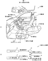
FIG. 1A is a schematic diagram inside a vehicle on which the operation input device according to the first embodiment is mounted, and FIG. 1B is an example of a block diagram of the operation input device. FIG. 2A is a block diagram illustrating an example of a vehicle communication system including the operation input device according to the first embodiment, and FIG. 2B illustrates a display screen of the display device in a screen lock state. It is the schematic which shows an example, FIG.2 (c) is a graph which shows an example of the detected electrostatic capacitance. Note that, in each drawing according to the embodiment described below, the ratio between figures may be different from the actual ratio. Further, in FIG. 1B, FIG. 2A, and later-described FIG. 4A and FIG. 6, the flow of main signals and information is indicated by arrows. In addition, “A to B” indicating a numerical range is used in the meaning of A or more and B or less.
操作入力装置1は、図1(a)に示すように、車両5の運転席51と助手席52の間に位置するフロアコンソール53に配置されている。操作入力装置1は、例えば、電磁気的に接続された電子機器の操作を行うことができるものである。つまり操作入力装置1は、例えば、導電性を有するペンや指による操作により、電子機器の表示部に表示されたカーソルの移動や選択、表示されたアイコンの選択、決定、ドラッグ、ドロップ等の指示を行うことができるように構成されている。本実施の形態では、指(操作指)による操作について説明する。 The operation input device 1 is disposed on a floor console 53 located between a driver seat 51 and a passenger seat 52 of the vehicle 5 as shown in FIG. The operation input device 1 can operate an electronic device that is electromagnetically connected, for example. In other words, the operation input device 1 is, for example, instructions such as movement and selection of the cursor displayed on the display unit of the electronic device, selection of the displayed icon, determination, dragging, dropping, etc. by operation with a conductive pen or finger. It is configured to be able to do. In this embodiment, an operation with a finger (operation finger) will be described.
この操作入力装置1は、図1(b)に示すように、タッチ検出部としてのタッチパッド10と、しきい値生成部12と、初期しきい値200及びタッチしきい値としての設定しきい値201を有する制御部20と、を備えて概略構成されている。
As shown in FIG. 1B, the operation input device 1 includes a
このしきい値生成部12は、被制御装置がタッチパッド10を介してなされた予め定められた操作以外の指示を受け付けないロック状態にある場合、タッチパッド10の操作面100になされた予め定められた操作に応じてタッチパッド10から出力された検出値のピーク値に基づいて操作面100になされた操作を判定するための設定しきい値201を生成するように構成されている。
This threshold
被制御装置とは、一例として、図2(a)に示すナビゲーション装置56、空調装置57、音楽再生装置58等の車両5に搭載された電子機器である。表示装置54は、例えば、これらの電子機器の表示部として機能するように構成されている。以下の実施の形態では、一例として、被制御装置がナビゲーション装置56である場合について説明する。
The controlled device is, for example, an electronic device mounted on the vehicle 5 such as the
予め定められた操作とは、一例として、操作面100を操作指で叩くような操作であるタップ操作であるが、これに限定されず、予め定められた図形を操作面100上に描くジェスチャ操作等であっても良い。
The predetermined operation is, for example, a tap operation that is an operation of hitting the
またロック状態とは、一例として、図2(b)に示すように、表示装置54の表示画面540に地図画像である表示画像541が表示されている場合、なぞり操作等の予め定められた操作であるタップ操作以外の操作をタッチパッド10に行っても地図画像がスクロールされたり、他の画像に切り替わったりしない状態である。以下では、このロック状態を画面ロック状態又は画面ロックと記載する。
As an example, the locked state is a predetermined operation such as a tracing operation when a display image 541 that is a map image is displayed on the display screen 540 of the
(タッチパッド10の構成)
タッチパッド10は、例えば、操作面100に操作者の操作指が近づく、又は接触することによる、操作面100の下方に配置された電極と操作指との間に形成される静電容量を検出する静電容量方式のタッチセンサである。
(Configuration of touchpad 10)
The
タッチパッド10は、例えば、検出した1周期分の検出値である静電容量を検出値情報S1として制御部20に出力する。この検出値は、一例として、静電容量を示すアナログ値をデジタル変換したデジタル値である。タッチパッド10は、操作指を検出すると、検出値が正の値を取るように構成されている。
(しきい値生成部12の構成)
しきい値生成部12は、タップ操作の判定に用いた検出値におけるピーク値に予め定められた定数を乗算することにより設定しきい値201を設定するように構成されている。
(Configuration of threshold generation unit 12)
The
上述の1周期分の検出値とは、例えば、操作面100にxy座標系が設定され、図2(b)の紙面において横軸がx、縦軸がyであり、x軸に直交するように検出側であるx電極が設置され、y軸に直交するように駆動側であるy電極が配置されている場合、このx電極とy電極の全ての組み合せをスキャンして得られた複数の検出値である。
The detection value for one period described above is such that, for example, an xy coordinate system is set on the
図2(c)は、タップ操作の判定に必要とされた複数の周期の検出値のうち、最大の検出値が得られた駆動側のy電極と、全てのx電極との組み合わせで得られた静電容量のグラフを示している。なお本実施の形態では、操作指を検出すると検出値が増加するように構成されているので、操作指を検出した際には、その座標における静電容量のグラフが上に凸となる。従ってピーク値は、最大値となる。なおタッチパッド10が操作指を検出すると検出値が減少するように構成されている場合、操作指を検出すると下に凸のグラフが得られるので、ピーク値は、負のピーク値、つまり最小値となる。
FIG. 2C is obtained by combining the drive-side y electrode that obtained the maximum detection value among the detection values of a plurality of periods required for the determination of the tap operation and all the x electrodes. A graph of the capacitance is shown. In the present embodiment, the detection value is increased when the operating finger is detected. Therefore, when the operating finger is detected, the capacitance graph at the coordinates is convex upward. Therefore, the peak value is the maximum value. If the
しきい値生成部12は、例えば、制御部20を介して取得したピーク値情報S2に基づくピーク値に予め定められた定数を乗算することにより設定しきい値201を生成する。この予め定められた定数は、例えば、0.6〜0.9の範囲の数であることが好ましく、0.7〜0.8の範囲の数であることがより好ましい。予め定められた定数は、一例として、0.8である。
しきい値生成部12は、生成した設定しきい値201をしきい値情報S3として制御部20に出力する。
(制御部20の構成)
制御部20は、例えば、記憶されたプログラムに従って、取得したデータに演算、加工等を行うCPU(Central Processing Unit)、半導体メモリであるRAM(Random Access Memory)及びROM(Read Only Memory)等から構成されるマイクロコンピュータである。このROMには、例えば、制御部20が動作するためのプログラムと、初期しきい値200と、設定しきい値201と、が格納されている。RAMは、例えば、一時的に演算結果等を格納する記憶領域として用いられる。また制御部20は、その内部にクロック信号を生成する手段を有し、このクロック信号に基づいて動作を行う。
(Configuration of control unit 20)
The
初期しきい値200は、例えば、電子機器が画面ロック状態にある場合、操作面100になされた操作を判定するためのしきい値である。
The initial threshold value 200 is a threshold value for determining an operation performed on the
制御部20は、例えば、画面ロック状態にある場合、検出値情報S1と初期しきい値200とを比較してタップ操作の有無を判定する。制御部20は、比較の結果、タップ操作が検出されると、検出値情報S1からピーク値を求め、このピーク値の情報であるピーク値情報S2を生成してしきい値生成部12に出力する。制御部20は、しきい値生成部12からしきい値情報S3が出力されると、このしきい値情報S3に基づいて設定しきい値201を記憶するように構成されている。なお制御部20は、タップ操作を判定するため、複数周期の検出値と初期しきい値200との比較を行う。
The
制御部20は、操作が検出されると、操作が検出されたxy座標系の座標の情報である操作情報S4を生成して接続された電子機器に出力する。
また制御部20は、例えば、図1(b)に示すように、画面ロック信号S5を取得する。この画面ロック信号S5は、接続された電子機器から出力され、電子機器が画面ロック状態にあるのか解除状態にあるのかを示す信号である。制御部20は、画面ロック状態を示す画面ロック信号S5が入力した後、タップ操作の有無を判定すると共に、タップ操作に基づくピーク値を求めてピーク値情報S2として出力する。
The
(車両通信システム500の構成)
車両通信システム500は、例えば、車両5に搭載された電子機器間の情報や信号の相互の交換を、車両LAN(Local Area Network)501を介して実行可能にするシステムである。
(Configuration of vehicle communication system 500)
The vehicle communication system 500 is, for example, a system that enables information and signals to be exchanged between electronic devices mounted on the vehicle 5 via a vehicle LAN (Local Area Network) 501.
この車両通信システム500は、例えば、図2(a)に示すように、操作入力装置1と、表示装置54と、車両制御部55と、ナビゲーション装置56と、空調装置57と、音楽再生装置58と、が車両LAN501を介して電磁気的に接続されている。なお操作入力装置1の被制御装置としての他の電子機器が車両LAN501に電磁気的に接続されても良い。
For example, as shown in FIG. 2A, the vehicle communication system 500 includes an operation input device 1, a
車両制御部55は、例えば、CPU、RAM及びROM等から構成されるマイクロコンピュータである。車両制御部55は、車両5に搭載された電子機器を総合的に制御するように構成されている。
The
操作入力装置1の被制御装置であるナビゲーション装置56、空調装置57及び音楽再生装置58は、一例として、画面ロック状態を示す画面ロック信号S5を出力し、操作入力装置1から出力された操作情報S4が入力するように構成されている。
The operation input device 1 of the
車両LAN501は、導電体による接続、電磁波の一種である光による接続、及び電磁波の一種である電波による接続の少なくとも1つを用いて各電子機器と接続する。 The vehicle LAN 501 is connected to each electronic device using at least one of a connection using a conductor, a connection using light that is a type of electromagnetic wave, and a connection using radio waves that is a type of electromagnetic wave.
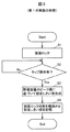
以下に、本実施の形態に係る操作入力装置1の設定しきい値201を生成する動作について図3のフローチャートに従って説明する。 Below, the operation | movement which produces | generates the setting threshold value 201 of the operation input apparatus 1 which concerns on this Embodiment is demonstrated according to the flowchart of FIG.
(動作)
操作入力装置1の制御部20は、画面ロック信号S5が入力し、電子機器が画面ロック状態にある場合(S1)、取得した複数の検出値情報S1の検出値と初期しきい値200とに基づいてタップ操作の有無を判定する。
(Operation)
制御部20は、ステップ2の「Yes」が成立する、つまりタップ操作が検出されたと判定すると(S2:Yes)、タップ操作の判定に用いた検出値からピーク値を求め、そのピーク値に基づくピーク値情報S2を生成してしきい値生成部12に出力する。
When it is determined that “Yes” in
しきい値生成部12は、取得したピーク値情報S2に基づく検出値のピーク値、つまり静電容量のピーク値に予め定められた定数を乗算して設定しきい値201を生成して制御部20に出力する(S3)。
制御部20は、タップ操作に基づいて操作情報S4を生成して電子機器に出力し、画面ロック状態を解除させ、しきい値生成部12から取得したしきい値情報S3に基づいた設定しきい値201を記憶する(S4)。制御部20は、この設定しきい値201に従って操作の判定を行う。以上により、操作入力装置1は、画面ロック状態解除による設定しきい値201の生成動作を終了する。
なお制御部20は、設定しきい値201の生成前に、画面ロック状態が電子機器側から解除されたことを示す画面ロック信号S5が入力した場合、設定しきい値201の生成動作を終了し、初期しきい値200によって操作の判定を行う。
Note the
(第1の実施の形態の効果)
本実施の形態に係る操作入力装置1は、操作時の状態に応じたしきい値を設定することができる。操作者が素手によって操作する場合、及び操作者が手袋を着用して操作する場合、同じ操作者でも、それぞれ検出される静電容量が異なる。また静電容量は、素手であっても指の太さの違いなどによる個人差により、検出される静電容量が異なる。その結果、例えば、しきい値を固定すると、手袋でなされた操作が検出されない場合や、想定よりも細い指でなされた操作の検出が安定せずに操作性が低下する可能性がある。またしきい値が手袋による操作が検出できるように低く設定される、つまり操作の検出感度が高く設定されると、素手の場合に、操作面から離れた状態で操作が検出され、操作者が意図しない不要な動作が電子機器において実行される可能性がある。しかし操作入力装置1は、画面ロック状態にある際のタップ操作に基づく検出値のピーク値を利用して設定しきい値201を設定するので、タップ操作を行った際の手の状態に応じて適切な設定しきい値201を設定することができる。また操作入力装置1は、操作時の状態に適した設定しきい値201を生成するので、検出感度が適正となり操作性が良い。
(Effects of the first embodiment)
Operation input device 1 concerning this embodiment can set up a threshold according to the state at the time of operation. When the operator operates with bare hands and when the operator wears gloves to operate, the detected capacitance differs even for the same operator. Moreover, even if it is a bare hand, the detected electrostatic capacitance changes with individual differences by the difference in the thickness of a finger, etc. As a result, for example, when the threshold value is fixed, there is a possibility that an operation performed with a glove is not detected or an operation performed with a finger thinner than expected is not stabilized and the operability is lowered. If the threshold is set low so that the operation with gloves can be detected, that is, if the detection sensitivity of the operation is set high, the operation is detected in the state of being away from the operation surface in the case of a bare hand, and the operator Unintended unnecessary operations may be performed in the electronic device. However, since the operation input device 1 sets the setting threshold value 201 using the peak value of the detection value based on the tap operation when the screen is locked, the operation input device 1 depends on the state of the hand when the tap operation is performed. An appropriate setting threshold 201 can be set. Further, since the operation input device 1 generates the setting threshold value 201 suitable for the state at the time of operation, the detection sensitivity is appropriate and the operability is good.
操作入力装置1は、画面ロック状態にある際に行われたタップ操作に基づいて設定しきい値200を生成するので、このタップ操作に基づく指示により電子機器が制御されることがなく、不要な動作が発生しない。 Since the operation input device 1 generates the setting threshold value 200 based on the tap operation performed when the screen is locked, the electronic device is not controlled by an instruction based on the tap operation, which is unnecessary. No action occurs.
[第2の実施の形態]
第2の実施の形態は、タッチパッド10に負荷された荷重を検出するための加速度センサが設けられている点で上述の実施の形態と異なっている。
[Second Embodiment]
The second embodiment is different from the above-described embodiment in that an acceleration sensor for detecting a load applied to the
図4(a)は、第2の実施の形態に係る操作入力装置の一例を示すブロック図であり、図4(b)は、加速度センサの配置を説明するための操作入力装置の一例を示す模式図である。なお以下に記載する実施の形態において、第1の実施の形態と同じ機能及び構成を有する部分は、第1の実施の形態と同じ符号を付し、その説明は省略するものとする。 FIG. 4A is a block diagram showing an example of the operation input device according to the second embodiment, and FIG. 4B shows an example of the operation input device for explaining the arrangement of the acceleration sensors. It is a schematic diagram. In the embodiments described below, parts having the same functions and configurations as those of the first embodiment are denoted by the same reference numerals as those of the first embodiment, and description thereof is omitted.
本実施の形態の操作入力装置1は、図4(a)及び図4(b)に示すように、タップ操作に伴って操作面100に負荷された荷重Lに基づく荷重信号としてのセンサ信号S6を出力する荷重検出部としての加速度センサ14を備えている。
As shown in FIGS. 4A and 4B, the operation input device 1 according to the present embodiment has a sensor signal S as a load signal based on a load L loaded on the
ここで、タッチパッドは、操作時の状態や設定されているしきい値によって、操作指が操作面に接触していなくても操作指を検出する可能性がある。操作指が操作面に接触していない状態で設定されたしきい値は、適正な検出感度よりも若干高くなり、不要な動作を検出することが考えられる。そこで、本実施の形態の操作入力装置1は、一例として、図4(b)に示すように、操作指9による操作の際に操作面100に負荷される荷重Lに基づく加速度を検出することにより、操作面100に対する操作指9の接触が伴うタップ操作を確実に検出し、より適正な検出感度をもたらす設定しきい値201の生成を行う。
Here, the touchpad may detect the operation finger even if the operation finger is not in contact with the operation surface, depending on a state at the time of operation or a set threshold value. The threshold value set in a state where the operation finger is not in contact with the operation surface is slightly higher than the appropriate detection sensitivity, and it is considered that an unnecessary operation is detected. Therefore, as an example, the operation input device 1 according to the present embodiment detects an acceleration based on a load L applied to the
加速度センサ14は、例えば、静電容量型又はピエゾ抵抗型の加速度センサである。本実施の形態の加速度センサ14は、一例として、静電容量型の加速度センサであり、検出した加速度をセンサ信号S6として制御部20に出力するように構成されている。
The
この加速度センサ14は、例えば、図4(b)に示すように、タッチパッド10の裏面101に配置されている。加速度センサ14は、例えば、4つの隅を支持部150により支持されたタッチパッド10になされた操作に基づく荷重Lに応じた加速度を検出する。
The
なお変形例として、荷重検出部は、例えば、操作に基づくタッチパッド10に負荷された荷重Lを検出可能な荷重センサ、歪センサ等であっても良い。
As a modification, the load detection unit may be, for example, a load sensor or a strain sensor that can detect a load L applied to the
また制御部20は、加速度センサ14から出力されたセンサ信号S6に基づいて操作がなされたと判定した場合、しきい値生成部12を制御して設定しきい値201を生成させる。
The
この制御部20は、荷重しきい値202を有し、取得したセンサ信号S6に基づいた荷重と荷重しきい値202とを比較して、当該荷重が荷重しきい値202よりも大きい場合、操作面100に操作指が接触した、つまりタッチパッド10に操作がなされと判定する。
The
以下に、本実施の形態の操作入力装置1の設定しきい値201を生成する動作について図5のフローチャートに従って説明する。 Below, the operation | movement which produces | generates the setting threshold value 201 of the operation input apparatus 1 of this Embodiment is demonstrated according to the flowchart of FIG.
(動作)
操作入力装置1の制御部20は、画面ロック信号S5が入力し、電子機器が画面ロック状態にある場合(S10)、取得した加速度センサ14のセンサ信号S6と荷重しきい値202とに基づいて、操作指の操作面100の接触の有無、つまり操作の有無を判定する。
(Operation)
Control unit of the operation input device 1 20 receives a screen lock signal S 5, when the electronic device is in the screen locked (S10), the sensor signal S 6 and the load threshold 202 of the
制御部20は、ステップ11の「Yes」が成立する、つまり操作が検出されたと判定すると(S11:Yes)、続いて取得した複数の検出値情報S1の検出値と初期しきい値200とに基づいてタップ操作の有無を判定する。
制御部20は、タップ操作が検出されたと判定すると(S12:Yes)、タップ操作の判定に用いた検出値からピーク値を求め、そのピーク値に基づくピーク値情報S2を生成してしきい値生成部12に出力する。
しきい値生成部12は、取得したピーク値情報S2に基づく検出値のピーク値、つまり静電容量のピーク値に予め定められた定数を乗算して設定しきい値201を生成して制御部20に出力する(S13)。
制御部20は、タップ操作に基づいて操作情報S4を生成して電子機器に出力し、画面ロック状態を解除させ、しきい値生成部12から取得したしきい値情報S3に基づいた設定しきい値201を記憶する(S14)。制御部20は、この設定しきい値201に従って操作の判定を行う。以上により、操作入力装置1は、画面ロック状態解除による設定しきい値201の生成動作を終了する。
ここでステップ12において、制御部20は、タップ操作が検出されていないと判定すると(S12:No)、ステップ11に戻って動作を継続する。
If the
なお制御部20は、設定しきい値201の生成前に、画面ロック状態が電子機器側から解除されたことを示す画面ロック信号S5が入力した場合、設定しきい値201の生成動作を終了し、初期しきい値200によって操作の判定を行う。
Note the
(第2の実施の形態の効果)
本実施の形態の操作入力装置1は、加速度センサ14によって、操作面100に対する操作指の接触を確実に判定するので、より適正な検出感度をもたらす設定しきい値201を生成することができる。
(Effect of the second embodiment)
Since the operation input device 1 according to the present embodiment reliably determines contact of the operation finger with the
[第3の実施の形態]
第3の実施の形態は、判定された座席ごとにしきい値を生成する点において上述の実施の形態と異なっている。
[Third Embodiment]
The third embodiment is different from the above-described embodiment in that a threshold value is generated for each determined seat.
図6は、第3の実施の形態に係る操作入力装置の一例を示すブロック図である。 FIG. 6 is a block diagram illustrating an example of the operation input device according to the third embodiment.
本実施の形態の操作入力装置1は、例えば、図6に示すように、操作者が車両5の運転席51及び助手席52のいずれの座席に着座しているのかを判別する判別部としての座席判別センサ16を備えている。
For example, as shown in FIG. 6, the operation input device 1 of the present embodiment serves as a determination unit that determines whether the operator is seated in the driver seat 51 or the passenger seat 52 of the vehicle 5. A
この座席判別センサ16は、例えば、図1(a)に示すように、運転席51に配置された検出電極510と、助手席52に配置された検出電極520と、を備えて概略構成されている。例えば、操作者が運転席51に着座して操作面100に接触すると、操作者を介してタッチパッド10と検出電極510とを含む回路が形成されて着座している座席を判別可能となる。
For example, as shown in FIG. 1A, the
座席判別センサ16は、操作者が着座する座席の情報である判別情報S7を生成して制御部20に出力する。
The
制御部20は、座席判別センサ16が判別する座席と設定しきい値とを関連付けて記憶し、判別された座席に関連付けられた設定しきい値と検出値とを比較した結果に応じて操作面100になされた操作を判定する。
The
この座席ごとの設定しきい値とは、例えば、運転席側の操作者が画面ロック状態を解除するために行ったタップ操作に基づいて生成されたD席用しきい値203、及び助手席側の操作者が画面ロック状態を解除するために行ったタップ操作に基づいて生成されたP席用しきい値204である。 The set threshold value for each seat is, for example, the threshold value 203 for the D seat generated based on the tap operation performed by the operator on the driver's seat side to release the screen lock state, and the passenger seat side P seat threshold value 204 generated based on the tap operation performed by the operator to release the screen lock state.
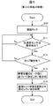
以下に、本実施の形態の操作入力装置1の動作について、図7のフローチャートに従って説明する。 Below, operation | movement of the operation input apparatus 1 of this Embodiment is demonstrated according to the flowchart of FIG.
(動作)
操作入力装置1の制御部20は、画面ロック信号S5が入力し、電子機器が画面ロック状態にある場合(S20)、取得した加速度センサ14のセンサ信号S6と荷重しきい値202とに基づいて、操作指の操作面100の接触の有無、つまり操作の有無を判定する。
(Operation)
When the screen lock signal S 5 is input and the electronic device is in the screen lock state (S 20), the
制御部20は、ステップ21の「Yes」が成立する、つまり操作が検出されたと判定すると(S21:Yes)、続いて取得した複数の検出値情報S1の検出値と初期しきい値200とに基づいてタップ操作の有無を判定する。
制御部20は、タップ操作が検出されたと判定すると(S22:Yes)、タップ操作の判定に用いた検出値からピーク値を求め、そのピーク値に基づくピーク値情報S2を生成してしきい値生成部12に出力する。
また座席判別センサ16は、検出電極510及び検出電極520が出力する信号に基づいて操作者が運転席(D席)側に着座するのか、助手席(P席)側に着座するのか判別し、判別した結果を判別情報S7として制御部20に出力する。
The
しきい値生成部12は、取得したピーク値情報S2に基づく検出値のピーク値、つまり静電容量のピーク値に予め定められた定数を乗算して設定しきい値を生成して制御部20に出力する。操作者がD席に着座していた場合(S23:D席)、制御部20は、生成された設定しきい値と判別されたD席とを関連付けたD席用しきい値203を生成して記憶する(S24)。
ここで、ステップ23において、操作者が助手席(P席)に着座していると判定された場合(S23:P席)、制御部20は、生成された設定しきい値と判別されたP席とを関連付けたP席用しきい値204を生成して記憶する(S25)。
Here, when it is determined in
以上、ステップ20〜ステップ25までが、D席用しきい値203及びP席用しきい値204の生成動作である。続いて、以下では、このD席用しきい値203及びP席用しきい値204を用いた操作の検出について説明する。
制御部20は、取得した加速度センサ14のセンサ信号S6と荷重しきい値202とに基づいて、操作指の操作面100の接触の有無、つまり操作の有無を判定する。制御部20は、ステップ26の「Yes」が成立する、つまり操作が検出されたと判定すると(S26:Yes)、続いて座席判別センサ16から取得した判別情報S7に基づいて操作者が着座している座席を判別する。
The
操作者がD席に着座していた場合(S27:D席)、制御部20は、D席用しきい値203を読み出す(S28)。
When the operator is seated in the D seat (S27: D seat), the
制御部20は、読み出したD席用しきい値203と検出値情報S1に基づく検出値とを比較し、操作がなされたか否かを判定する。制御部20は、検出値がD席用しきい値203より大きい場合(S29:Yes)、検出された操作に基づいて操作情報S4を生成し、出力する(S30)。
The
ここでステップ29において、制御部20は、検出値がD席用しきい値203以下であった場合(S29:No)、ステップ26に戻って動作を継続する。
Here, in
また操作者がP席に着座していた場合(S27:P席)、制御部20は、P席用しきい値204を読み出す(S31)。
When the operator is seated in the P seat (S27: P seat), the
制御部20は、読み出したP席用しきい値204と検出値情報S1に基づく検出値とを比較し、操作がなされたか否かを判定する。制御部20は、検出値がP席用しきい値204より大きい場合(S32:Yes)、検出された操作に基づいて操作情報S4を生成し、出力する(S30)。
The
ここでステップ32において、制御部20は、検出値がP席用しきい値204以下であった場合(S32:No)、ステップ26に戻って動作を継続する。
Here, in
次に、制御部20は、電子機器がタイムアウトによる画面ロックを指示するために出力した画面ロック信号S5の入力、又は操作者の操作によって電子機器が画面ロック状態に移行した場合(S33:Yes)、D席用しきい値203及びP席用しきい値204をリセット、つまり消去する。このリセットの後、制御部20は、電子機器が画面ロック状態に入ったので、初期しきい値200により操作の有無を判定する。
Next, the
ここで、ステップ33において、制御部20は、画面ロック信号S5の入力、又は画面ロック状態への移行がない場合(S33:No)、ステップ26に戻って動作を継続する。
Here, in
なお制御部20は、例えば、判別された座席に関連したしきい値が記憶されていない場合、初期しきい値200を用いて操作を判定する。
The
(第3の実施の形態の効果)
本実施の形態の操作入力装置1は、判定された座席ごとにしきい値を生成するので、この構成を採用しない場合と比べて、さらに操作時の状態に適したしきい値を設定することができる。
(Effect of the third embodiment)
Since the operation input device 1 according to the present embodiment generates a threshold value for each determined seat, it is possible to set a threshold value that is more suitable for the state during operation than when this configuration is not adopted. it can.
上述の実施の形態及び変形例に係る操作入力装置1は、例えば、用途に応じて、その一部が、コンピュータが実行するプログラム、ASIC(Application Specific Integrated Circuit)及びFPGA(Field Programmable Gate Array)等によって実現されても良い。 The operation input device 1 according to the above-described embodiment and modification is, for example, a program executed by a computer, an ASIC (Application Specific Integrated Circuit), an FPGA (Field Programmable Gate Array), or the like depending on applications. It may be realized by.
以上、本発明のいくつかの実施の形態及び変形例を説明したが、これらの実施の形態及び変形例は、一例に過ぎず、特許請求の範囲に係る発明を限定するものではない。これら新規な実施の形態及び変形例は、その他の様々な形態で実施されることが可能であり、本発明の要旨を逸脱しない範囲で、種々の省略、置き換え、変更等を行うことができる。また、これら実施の形態及び変形例の中で説明した特徴の組合せの全てが発明の課題を解決するための手段に必須であるとは限らない。さらに、これら実施の形態及び変形例は、発明の範囲及び要旨に含まれるとともに、特許請求の範囲に記載された発明とその均等の範囲に含まれる。 As mentioned above, although some embodiment and modification of this invention were demonstrated, these embodiment and modification are only examples, and do not limit the invention based on a claim. These novel embodiments and modifications can be implemented in various other forms, and various omissions, replacements, changes, and the like can be made without departing from the scope of the present invention. In addition, not all combinations of features described in these embodiments and modifications are necessarily essential to the means for solving the problems of the invention. Furthermore, these embodiments and modifications are included in the scope and gist of the invention, and are included in the invention described in the claims and the equivalents thereof.
1…操作入力装置、5…車両、9…操作指、10…タッチパッド、12…しきい値生成部、14…加速度センサ、16…座席判別センサ、20…制御部、51…運転席、52…助手席、53…フロアコンソール、54…表示装置、55…車両制御部、56…ナビゲーション装置、57…空調装置、58…音楽再生装置、100…操作面、101…裏面、150…支持部、200…初期しきい値、201…設定しきい値、202…荷重しきい値、203…D席用しきい値、204…P席用しきい値、500…車両通信システム、501…車両LAN、510,520…検出電極、540…表示画面、541…表示画像 DESCRIPTION OF SYMBOLS 1 ... Operation input device, 5 ... Vehicle, 9 ... Operation finger, 10 ... Touch pad, 12 ... Threshold generation part, 14 ... Acceleration sensor, 16 ... Seat discrimination sensor, 20 ... Control part, 51 ... Driver's seat, 52 ... Passenger seat, 53 ... Floor console, 54 ... Display device, 55 ... Vehicle control unit, 56 ... Navigation device, 57 ... Air conditioner, 58 ... Music player, 100 ... Operation surface, 101 ... Back surface, 150 ... Support portion, 200 ... Initial threshold value, 201 ... Setting threshold value, 202 ... Load threshold value, 203 ... D seat threshold value, 204 ... P seat threshold value, 500 ... Vehicle communication system, 501 ... Vehicle LAN, 510, 520 ... detection electrodes, 540 ... display screen, 541 ... display image
Claims (4)
前記予め定められた操作に伴って前記操作面に負荷された荷重に基づく荷重信号を出力する荷重検出部と、
前記荷重検出部から出力された前記荷重信号に基づいて前記予め定められた操作がなされたと判定した場合、前記しきい値生成部を制御して前記タッチしきい値を生成させる制御部と、
を備えた請求項1に記載の操作入力装置。 The touch detection unit;
A load detection unit that outputs a load signal based on a load applied to the operation surface in accordance with the predetermined operation;
A control unit that controls the threshold value generation unit to generate the touch threshold value when it is determined that the predetermined operation has been performed based on the load signal output from the load detection unit;
The operation input device according to claim 1, further comprising:
前記制御部は、前記判別部が判別する座席と前記タッチしきい値とを関連付けて記憶し、判別された座席に関連付けられた前記タッチしきい値と前記検出値とを比較した結果に応じて前記操作面になされた操作を判定する、
請求項2に記載の操作入力装置。 Furthermore, a determination unit for determining whether the operator is seated in a driver seat or a passenger seat of the vehicle,
The control unit stores the seat determined by the determination unit and the touch threshold in association with each other, and according to a result of comparing the touch threshold associated with the determined seat with the detected value. Determining an operation performed on the operation surface;
The operation input device according to claim 2.
請求項1乃至3に記載の操作入力装置。 The threshold generation unit sets the touch threshold by multiplying the peak value in the detection value used for determination of the predetermined operation by a predetermined constant;
The operation input device according to claim 1.
Priority Applications (1)
| Application Number | Priority Date | Filing Date | Title |
|---|---|---|---|
| JP2015043581A JP2016159882A (en) | 2015-03-05 | 2015-03-05 | Operation input device |
Applications Claiming Priority (1)
| Application Number | Priority Date | Filing Date | Title |
|---|---|---|---|
| JP2015043581A JP2016159882A (en) | 2015-03-05 | 2015-03-05 | Operation input device |
Publications (1)
| Publication Number | Publication Date |
|---|---|
| JP2016159882A true JP2016159882A (en) | 2016-09-05 |
Family
ID=56846018
Family Applications (1)
| Application Number | Title | Priority Date | Filing Date |
|---|---|---|---|
| JP2015043581A Pending JP2016159882A (en) | 2015-03-05 | 2015-03-05 | Operation input device |
Country Status (1)
| Country | Link |
|---|---|
| JP (1) | JP2016159882A (en) |
Cited By (1)
| Publication number | Priority date | Publication date | Assignee | Title |
|---|---|---|---|---|
| CN110998500A (en) * | 2017-08-08 | 2020-04-10 | 株式会社东海理化电机制作所 | Operation detection device |
Citations (6)
| Publication number | Priority date | Publication date | Assignee | Title |
|---|---|---|---|---|
| JP2008033701A (en) * | 2006-07-31 | 2008-02-14 | Mitsubishi Motors Corp | Touch panel device |
| JP2009009098A (en) * | 2007-05-25 | 2009-01-15 | Seiko Epson Corp | Display device and detecting method |
| WO2013021858A1 (en) * | 2011-08-05 | 2013-02-14 | Necカシオモバイルコミュニケーションズ株式会社 | Information input unit, information input method, and computer program |
| JP2014056460A (en) * | 2012-09-13 | 2014-03-27 | Tokai Rika Co Ltd | Input device |
| JP2015106162A (en) * | 2013-11-28 | 2015-06-08 | 株式会社デンソー | Electronic device |
| JP2016010111A (en) * | 2014-06-26 | 2016-01-18 | 京セラ株式会社 | Portable communication terminal, call termination control program and call termination control method |
-
2015
- 2015-03-05 JP JP2015043581A patent/JP2016159882A/en active Pending
Patent Citations (6)
| Publication number | Priority date | Publication date | Assignee | Title |
|---|---|---|---|---|
| JP2008033701A (en) * | 2006-07-31 | 2008-02-14 | Mitsubishi Motors Corp | Touch panel device |
| JP2009009098A (en) * | 2007-05-25 | 2009-01-15 | Seiko Epson Corp | Display device and detecting method |
| WO2013021858A1 (en) * | 2011-08-05 | 2013-02-14 | Necカシオモバイルコミュニケーションズ株式会社 | Information input unit, information input method, and computer program |
| JP2014056460A (en) * | 2012-09-13 | 2014-03-27 | Tokai Rika Co Ltd | Input device |
| JP2015106162A (en) * | 2013-11-28 | 2015-06-08 | 株式会社デンソー | Electronic device |
| JP2016010111A (en) * | 2014-06-26 | 2016-01-18 | 京セラ株式会社 | Portable communication terminal, call termination control program and call termination control method |
Cited By (1)
| Publication number | Priority date | Publication date | Assignee | Title |
|---|---|---|---|---|
| CN110998500A (en) * | 2017-08-08 | 2020-04-10 | 株式会社东海理化电机制作所 | Operation detection device |
Similar Documents
| Publication | Publication Date | Title |
|---|---|---|
| JP5768347B2 (en) | Information processing apparatus, information processing method, and computer program | |
| JP5232431B2 (en) | Multi-touch determination device, method and recording medium | |
| JP5643719B2 (en) | Coordinate detection device | |
| KR101157592B1 (en) | Input device and touch position detecting method thereof | |
| US20150301684A1 (en) | Apparatus and method for inputting information | |
| US20150042576A1 (en) | Information Processing Method and Electronic Apparatus | |
| US10156927B2 (en) | Operation detecting device for detecting the presence of a foreign object on an operation surface | |
| JP6230062B2 (en) | Information processing device | |
| US20170300109A1 (en) | Method of blowable user interaction and an electronic device capable of blowable user interaction | |
| US10649555B2 (en) | Input interface device, control method and non-transitory computer-readable medium | |
| JP2012099005A (en) | Input device, input method, and input program | |
| JP6370118B2 (en) | Information processing apparatus, information processing method, and computer program | |
| JP2014109883A (en) | Electronic apparatus and method of controlling the same | |
| JP2016159882A (en) | Operation input device | |
| JP2006085218A (en) | Touch panel operating device | |
| JP7094631B2 (en) | Input device | |
| JP6271388B2 (en) | Electrostatic detection device | |
| US20130050081A1 (en) | 3d sensing method and system using a touch panel | |
| JP6770718B2 (en) | Tactile presentation device | |
| WO2014002315A1 (en) | Operation device | |
| JP2018120458A (en) | Operation device | |
| KR101571301B1 (en) | Feedback method of touch level and device including touch screen performing the same | |
| JP2016091494A (en) | Input device | |
| JP2005234958A (en) | Touch panel device | |
| JP2012098784A (en) | Input device and method for electronic device |
Legal Events
| Date | Code | Title | Description |
|---|---|---|---|
| A621 | Written request for application examination |
Free format text: JAPANESE INTERMEDIATE CODE: A621 Effective date: 20170620 |
|
| A977 | Report on retrieval |
Free format text: JAPANESE INTERMEDIATE CODE: A971007 Effective date: 20180322 |
|
| A131 | Notification of reasons for refusal |
Free format text: JAPANESE INTERMEDIATE CODE: A131 Effective date: 20180424 |
|
| A02 | Decision of refusal |
Free format text: JAPANESE INTERMEDIATE CODE: A02 Effective date: 20181023 |