JP2016018103A - Optical element and display device - Google Patents

Optical element and display device Download PDF

Info

Publication number
JP2016018103A
JP2016018103A JP2014141309A JP2014141309A JP2016018103A JP 2016018103 A JP2016018103 A JP 2016018103A JP 2014141309 A JP2014141309 A JP 2014141309A JP 2014141309 A JP2014141309 A JP 2014141309A JP 2016018103 A JP2016018103 A JP 2016018103A
Authority
JP
Japan
Prior art keywords
light
optical element
light transmissive
transmissive member
external
Prior art date
Legal status (The legal status is an assumption and is not a legal conclusion. Google has not performed a legal analysis and makes no representation as to the accuracy of the status listed.)
Pending
Application number
JP2014141309A
Other languages
Japanese (ja)
Inventor
坂田 秀文
Hidefumi Sakata
秀文 坂田
橋爪 俊明
Toshiaki Hashizume
俊明 橋爪
Current Assignee (The listed assignees may be inaccurate. Google has not performed a legal analysis and makes no representation or warranty as to the accuracy of the list.)
Seiko Epson Corp
Original Assignee
Seiko Epson Corp
Priority date (The priority date is an assumption and is not a legal conclusion. Google has not performed a legal analysis and makes no representation as to the accuracy of the date listed.)
Filing date
Publication date
Application filed by Seiko Epson Corp filed Critical Seiko Epson Corp
Priority to JP2014141309A priority Critical patent/JP2016018103A/en
Publication of JP2016018103A publication Critical patent/JP2016018103A/en
Pending legal-status Critical Current

Links

Images

Landscapes

  • Devices For Indicating Variable Information By Combining Individual Elements (AREA)

Abstract

PROBLEM TO BE SOLVED: To provide an optical element that can suppress distortion of an image of an external object, and a display device using the optical element.SOLUTION: The optical element includes a first light-transmitting member 21 having a first face 21a, a second face 21b, and a first reflective part 24 including a plurality of projections 24a; a second light-transmitting member 22 having a third face 22a, a fourth face 22b, and a second reflective part 25 including a plurality of recesses 25a; and a light-transmitting layer 23 having a refractive index different from the refractive index of the first light-transmitting member 21 and from the refractive index of the second light-transmitting member 22. Each of the plurality of projections 24a has a first inclined face 26a inclined with respect to the second face 21b; and each of the plurality of recesses 25a has a second inclined face 27a inclined with respect to the fourth face 22b. The first light-transmitting member 21 and the second light-transmitting member 22 are disposed in such a manner that the plurality of projections 24a meshes with the plurality of recesses 25a via the light-transmitting layer 23.SELECTED DRAWING: Figure 2

Description

本発明は、光学素子、及び表示装置に関する。   The present invention relates to an optical element and a display device.

例えば、特許文献1に示されるように、ハーフミラーを備えたヘッドアップディスプレイ等の表示装置が提案されている。
しかし、このような表示装置では、ハーフミラーが湾曲しているため、ハーフミラーの設置領域が大きくなり、表示装置全体が大型化する問題があった。
For example, as disclosed in Patent Document 1, a display device such as a head-up display including a half mirror has been proposed.
However, in such a display device, since the half mirror is curved, there is a problem that the installation area of the half mirror becomes large and the entire display device becomes large.

これに対して、上記のような表示装置のハーフミラーとして、例えば、特許文献2に示されるようなフレネルレンズ構造を有する積層体を用いることが考えられる。このような積層体は表面を平らにしつつ、ハーフミラーとしての機能を持たせることができるため、表示装置において積層体の設置領域を低減でき、表示装置全体を小型化できる。   On the other hand, it is conceivable to use a laminate having a Fresnel lens structure as disclosed in Patent Document 2, for example, as the half mirror of the display device as described above. Since such a laminated body can have a function as a half mirror while flattening the surface, the installation area of the laminated body can be reduced in the display device, and the entire display device can be downsized.

特開平11−30764号公報Japanese Patent Laid-Open No. 11-30764 特開2007−206657号公報JP 2007-206657 A

しかし、上記のようなフレネルレンズ構造を有する積層体、すなわち、光学素子では、フレネルレンズ構造によって積層体を透過する光は屈折され、入射した方向と異なる方向に射出される。そのため、積層体越しに視認される外部の物体の像が歪むという問題があった。   However, in a laminated body having a Fresnel lens structure as described above, that is, an optical element, light transmitted through the laminated body is refracted by the Fresnel lens structure and emitted in a direction different from the incident direction. Therefore, there has been a problem that an image of an external object visually recognized through the laminated body is distorted.

本発明の一つの態様は、上記問題点に鑑みて成されたものであって、外部の物体の像が歪むことを抑制できる光学素子、及びそのような光学素子を用いた表示装置を提供することを目的の一つとする。   One aspect of the present invention is made in view of the above problems, and provides an optical element capable of suppressing distortion of an image of an external object, and a display device using such an optical element. One of the purposes.

本発明の光学素子の一つの態様は、第1の面と、該第1の面と対向する第2の面と、該第2の面に設けられた複数の凸部を含む第1の反射部と、を備えた第1の光透過性部材と、第3の面と、該第3の面と対向する第4の面と、該第4の面に設けられ、前記複数の凸部に倣う複数の凹部を含む第2の反射部と、を備えた第2の光透過性部材と、前記第1の光透過性部材の屈折率及び前記第2の光透過性部材の屈折率と異なる屈折率を持つ光透過層と、を有し、前記複数の凸部の各々は、前記第2の面に対して傾いた第1の傾斜面を備え、前記複数の凹部の各々は、前記第4の面に対して傾いた第2の傾斜面を備え、前記複数の凸部が前記光透過層を介して前記複数の凹部とかみ合うように、前記第1の光透過性部材と前記第2の光透過性部材とが配置されていることを特徴とする。   According to one aspect of the optical element of the present invention, the first reflection includes a first surface, a second surface facing the first surface, and a plurality of convex portions provided on the second surface. A first light transmissive member provided with a portion, a third surface, a fourth surface opposite to the third surface, and the fourth surface. A second light transmissive member including a second reflecting portion including a plurality of concave portions to be copied, and a refractive index of the first light transmissive member and a refractive index of the second light transmissive member are different from each other. A light transmission layer having a refractive index, and each of the plurality of convex portions includes a first inclined surface inclined with respect to the second surface, and each of the plurality of concave portions includes the first A second inclined surface inclined with respect to the surface of the first light transmitting member and the second light transmitting member so that the plurality of convex portions engage with the plurality of concave portions via the light transmitting layer. Light transmissive member Wherein the but are arranged.

本発明の光学素子の一つの態様によれば、第1の反射部の凸部と、凸部に倣う第2の反射部の凹部とが光透過層を介してかみ合うように配置されている。そのため、光学素子に入射した光のうち透過する光は、凸部と光透過層との境界と、凹部と光透過層との境界とにおいて、互いに逆向きに屈折される。これにより、光学素子に入射する光の方向と、光学素子から射出される光の方向と、がほぼ平行となる。したがって、本発明の光学素子の一つの態様によれば、外部の物体の像が歪むことを抑制できる。   According to one aspect of the optical element of the present invention, the convex portion of the first reflective portion and the concave portion of the second reflective portion that follows the convex portion are arranged so as to engage with each other via the light transmission layer. Therefore, the transmitted light among the light incident on the optical element is refracted in opposite directions at the boundary between the convex portion and the light transmission layer and at the boundary between the concave portion and the light transmission layer. Thereby, the direction of the light incident on the optical element and the direction of the light emitted from the optical element become substantially parallel. Therefore, according to one aspect of the optical element of the present invention, distortion of an image of an external object can be suppressed.

前記複数の凸部は、フレネルレンズ構造を構成してもよい。
この構成によれば、第1の光透過性部材側から入射した光のうち反射される光を集光することができる。
The plurality of convex portions may constitute a Fresnel lens structure.
According to this configuration, it is possible to collect the reflected light among the light incident from the first light transmissive member side.

前記複数の凸部は、三角形状の断面を持つ凸部を含む構成としてもよい。
この構成によれば、凸部の形成が容易である。
The plurality of convex portions may include a convex portion having a triangular cross section.
According to this configuration, it is easy to form the convex portion.

前記複数の凸部はストライプ構造を構成し、前記第1の光透過性部材から前記第2の光透過性部材側へ向かって進行する光を第1の方向に反射する構成としてもよい。
この構成によれば、第1の光透過性部材側から入射する光のうち反射する光を偏向させることができる。
The plurality of convex portions may form a stripe structure, and may reflect light traveling in the first direction from the first light transmissive member toward the second light transmissive member.
According to this configuration, it is possible to deflect the reflected light among the light incident from the first light transmitting member side.

前記複数の凸部は、第1の凸部と、該第1の凸部に隣り合う第2の凸部と、該第1の凸部が備える前記第1の傾斜面を該第2の凸部が備える前記第1の傾斜面と接続する第1の接続面と、該第1の接続面に設けられた第1の光吸収部材と、を更に備える構成としてもよい。
この構成によれば、バックカット部に斜めに入射した光や、迷光による視認性の低下を抑制できる。
The plurality of convex portions include a first convex portion, a second convex portion adjacent to the first convex portion, and the first inclined surface included in the first convex portion. It is good also as a structure further provided with the 1st connection surface connected to the said 1st inclined surface with which a part is provided, and the 1st light absorption member provided in this 1st connection surface.
According to this configuration, it is possible to suppress degradation in visibility due to light obliquely incident on the back cut portion and stray light.

前記複数の凹部は、第1の凹部と、該第1の凹部に隣り合う第2の凹部と、該第1の凹部が備える前記第2の傾斜面を該第2の凹部が備える前記第2の傾斜面と接続する第2の接続面と、該第2の接続面に設けられた第2の光吸収部材と、を更に備える構成としてもよい。
この構成によれば、バックカット部に斜めに入射した光や、迷光による視認性の低下を抑制できる。
The plurality of concave portions include a first concave portion, a second concave portion adjacent to the first concave portion, and the second inclined surface provided in the first concave portion. It is good also as a structure further provided with the 2nd connection surface connected to this inclined surface, and the 2nd light absorption member provided in this 2nd connection surface.
According to this configuration, it is possible to suppress degradation in visibility due to light obliquely incident on the back cut portion and stray light.

前記第1の面と前記第3の面とのうち少なくとも一方は曲面部を持ち、前記第1の光透過性部材側から前記第2の光透過性部材側へ向かって進行する光に対する前記第1の反射部の偏向作用は、該光に対する前記曲面部の偏向作用と異なる構成としてもよい。
この構成によれば、異なる方向から入射した光を同じ方向に反射することができる。
At least one of the first surface and the third surface has a curved portion, and the first surface with respect to light traveling from the first light transmissive member side toward the second light transmissive member side. The deflecting action of one reflecting part may be different from the deflecting action of the curved surface part with respect to the light.
According to this configuration, light incident from different directions can be reflected in the same direction.

前記光透過層は、金属からなる構成としてもよい。
この構成によれば、厚みを調整することで、光透過層の反射率と透過率とを調整できる。
The light transmission layer may be made of a metal.
According to this configuration, the reflectance and transmittance of the light transmission layer can be adjusted by adjusting the thickness.

本発明の表示装置の一つの態様は、画像光を射出する画像形成装置と、前記画像光の光路上に設けられた上記の光学素子と、を備えることを特徴とする。
本発明の表示装置の一つの態様によれば、上記の光学素子を備えているため、外部の物体の像が歪むことを抑制できる。
One aspect of the display device of the present invention includes an image forming apparatus that emits image light, and the optical element that is provided on an optical path of the image light.
According to one aspect of the display device of the present invention, since the optical element is provided, distortion of an image of an external object can be suppressed.

第1実施形態の表示装置を示す概略構成図である。It is a schematic block diagram which shows the display apparatus of 1st Embodiment. 第1実施形態の光学素子を示す部分拡大断面である。It is a partial expanded section which shows the optical element of 1st Embodiment. 第1実施形態の光学素子を示す部分拡大断面である。It is a partial expanded section which shows the optical element of 1st Embodiment. 第1実施形態の光学素子を示す平面図である。It is a top view which shows the optical element of 1st Embodiment. 第1実施形態の光学素子の他の一例を示す部分拡大断面図である。It is a partial expanded sectional view which shows another example of the optical element of 1st Embodiment. 第1実施形態の光学素子の他の一例を示す部分拡大断面図である。It is a partial expanded sectional view which shows another example of the optical element of 1st Embodiment. 第2実施形態の表示装置を示す概略構成図である。It is a schematic block diagram which shows the display apparatus of 2nd Embodiment. 第3実施形態の表示装置を示す概略構成図である。It is a schematic block diagram which shows the display apparatus of 3rd Embodiment. 第3実施形態の光学素子を示す斜視図である。It is a perspective view which shows the optical element of 3rd Embodiment. 第3実施形態の表示装置の他の一例を示す概略構成図である。It is a schematic block diagram which shows another example of the display apparatus of 3rd Embodiment. 第4実施形態の表示装置を示す概略構成図である。It is a schematic block diagram which shows the display apparatus of 4th Embodiment.

以下、図面を参照しながら、本発明の実施形態に係る表示装置について説明する。
なお、本発明の範囲は、以下の実施の形態に限定されるものではなく、本発明の技術的思想の範囲内で任意に変更可能である。また、以下の図面においては、各構成をわかりやすくするために、実際の構造と各構造における縮尺や数等を異ならせる場合がある。
Hereinafter, a display device according to an embodiment of the present invention will be described with reference to the drawings.
The scope of the present invention is not limited to the following embodiment, and can be arbitrarily changed within the scope of the technical idea of the present invention. Moreover, in the following drawings, in order to make each structure easy to understand, the actual structure may be different from the scale, number, or the like in each structure.

また、図面においては、適宜3次元直交座標系としてXYZ座標系を示し、Z軸方向を鉛直線方向とし、Y軸方向とX軸方向とを水平方向とする。Y軸方向は、図1に示す観測者Mの視線Maの方向である。+Y向きが、観測者Mの視線Maの向きである。   In the drawings, an XYZ coordinate system is appropriately shown as a three-dimensional orthogonal coordinate system, the Z-axis direction is a vertical line direction, and the Y-axis direction and the X-axis direction are horizontal directions. The Y-axis direction is the direction of the line of sight Ma of the observer M shown in FIG. The + Y direction is the direction of the line of sight Ma of the observer M.

(第1実施形態)
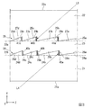
図1は、本実施形態の表示装置10を示す概略構成図である。図2から図4は、光学素子20を示す図である。図2及び図3は、部分拡大断面図である。図4は、平面図である。なお、図1及び図2においては、光吸収部材の図示を省略している。
(First embodiment)
FIG. 1 is a schematic configuration diagram illustrating a display device 10 according to the present embodiment. 2 to 4 are diagrams showing the optical element 20. 2 and 3 are partially enlarged sectional views. FIG. 4 is a plan view. In FIG. 1 and FIG. 2, the illustration of the light absorbing member is omitted.

本実施形態の表示装置10は、図1に示すように、画像形成装置30と、光学素子20と、を備える。本実施形態の表示装置10は、ヘッドアップディスプレイである。観測者Mは、光学素子20を挟んで位置する外部の物体の像、すなわち、外部の景色を視認するとともに、画像形成装置30による画像を視認する。以下の説明においては、+Y側を外部側、−Y側を視認側とする。   As shown in FIG. 1, the display device 10 of the present embodiment includes an image forming device 30 and an optical element 20. The display device 10 of the present embodiment is a head-up display. The observer M visually recognizes an image of an external object located across the optical element 20, that is, an external scenery, and visually recognizes an image by the image forming apparatus 30. In the following description, the + Y side is the external side, and the -Y side is the viewing side.

画像形成装置30は、後述する光学素子20に形成されたフレネルレンズ構造の焦点よりも、光学素子20に近い位置に配置されている。画像形成装置30は、図示は省略するが、例えば、赤、緑、青の光をそれぞれ変調して画像光を形成する複数の液晶パネルと、各液晶パネルから射出された画像光を合成する画像光合成系と、合成した光を射出する投射光学系と、を備える。これにより、画像形成装置30から3色の画像光が合成された画像光Lが光学素子20に向けて射出される。   The image forming apparatus 30 is disposed at a position closer to the optical element 20 than the focal point of the Fresnel lens structure formed on the optical element 20 described later. Although not shown, the image forming apparatus 30, for example, combines a plurality of liquid crystal panels that form image light by modulating red, green, and blue light and image light that is emitted from each liquid crystal panel. A photosynthesis system; and a projection optical system that emits the synthesized light. As a result, the image light L obtained by combining the three color image lights is emitted from the image forming apparatus 30 toward the optical element 20.

光学素子20は、視認側光透過性部材21と、外部側光透過性部材22と、光透過層23と、を備える。視認側光透過性部材21は、特許請求の範囲の第1の光透過性部材に相当し、外部側光透過性部材22は、特許請求の範囲の第2の光透過性部材に相当する。   The optical element 20 includes a viewing side light transmissive member 21, an external side light transmissive member 22, and a light transmissive layer 23. The viewing side light transmissive member 21 corresponds to a first light transmissive member in the claims, and the external side light transmissive member 22 corresponds to a second light transmissive member in the claims.

視認側光透過性部材21は、図2に示すように、視認面21aと、形成面21bと、視認側反射部24と、を備える。また、視認側光透過性部材21は、図3に示すように、複数の光吸収部材を備える。視認面21aは、特許請求の範囲の第1の面に相当する。形成面21bは、特許請求の範囲の第2の面に相当する。視認側反射部24は、特許請求の範囲の第1の反射部に相当する。   As shown in FIG. 2, the viewing-side light transmissive member 21 includes a viewing surface 21 a, a forming surface 21 b, and a viewing-side reflecting portion 24. Moreover, the viewing side light transmissive member 21 includes a plurality of light absorbing members as shown in FIG. The viewing surface 21a corresponds to the first surface of the claims. The formation surface 21b corresponds to the second surface of the claims. The viewing side reflection part 24 is equivalent to the 1st reflection part of a claim.

視認側光透過性部材21の平面視(ZX面視)形状は、特に限定されず、矩形状であっても、多角形状であっても、円形状であってもよい。本実施形態においては、視認側光透過性部材21の平面視(ZX面視)形状は、例えば、図4に示すように、矩形状である。   The planar view (ZX plane view) shape of the viewing-side light transmissive member 21 is not particularly limited, and may be rectangular, polygonal, or circular. In this embodiment, the planar view (ZX plane view) shape of the visual recognition side light transmissive member 21 is, for example, a rectangular shape as shown in FIG.

視認面21aは、図1に示すように、視認側光透過性部材21の観測者M側の面である。本実施形態において視認面21aは、平面である。図1においては、観測者Mの視線Maが、視認面21aに直交する場合を示している。視認面21aには、画像形成装置30から画像光Lが入射される。
形成面21bは、視認面21aと対向する面である。形成面21bには、図2に示すように、視認側反射部24が設けられている。
As shown in FIG. 1, the viewing surface 21 a is a surface on the viewer M side of the viewing-side light transmissive member 21. In the present embodiment, the visual recognition surface 21a is a flat surface. FIG. 1 shows a case where the line of sight Ma of the observer M is orthogonal to the viewing surface 21a. The image light L is incident on the viewing surface 21a from the image forming apparatus 30.
The formation surface 21b is a surface facing the visual recognition surface 21a. As shown in FIG. 2, a viewing-side reflecting portion 24 is provided on the formation surface 21 b.

視認側反射部24は、複数の凸部を含む。視認側反射部24は、入射した光の少なくとも一部を反射させ、入射した光の少なくとも一部を透過させる。
複数の凸部は、形成面21bから光透過層23側(+Y側)に突出して設けられている。複数の凸部は、本実施形態においては凸型のフレネルレンズ構造を構成している。各凸部は、傾斜面(第1の傾斜面)を備える。複数の凸部は、中央凸部24aと、複数の円環状凸部と、を含む。以下の説明においては、複数の円環状凸部を代表して円環状凸部24bと円環状凸部24cと円環状凸部24dとについて説明する。
The viewing side reflection part 24 includes a plurality of convex parts. The viewing-side reflecting unit 24 reflects at least a part of the incident light and transmits at least a part of the incident light.
The plurality of convex portions are provided so as to protrude from the formation surface 21b to the light transmission layer 23 side (+ Y side). The plurality of convex portions constitutes a convex Fresnel lens structure in the present embodiment. Each convex part is provided with an inclined surface (first inclined surface). The plurality of convex portions includes a central convex portion 24a and a plurality of annular convex portions. In the following description, the annular convex portion 24b, the annular convex portion 24c, and the annular convex portion 24d will be described on behalf of the plurality of annular convex portions.

なお、中央凸部24aと円環状凸部24bと円環状凸部24cと円環状凸部24dとは、特許請求の範囲の凸部に相当する。さらに、円環状凸部24bは第1の凸部に相当し、円環状凸部24bに隣り合う円環状凸部24cは第2の凸部に相当する。   The central convex portion 24a, the annular convex portion 24b, the annular convex portion 24c, and the annular convex portion 24d correspond to the convex portions in the claims. Furthermore, the annular convex part 24b corresponds to a first convex part, and the annular convex part 24c adjacent to the annular convex part 24b corresponds to a second convex part.

中央凸部24aは、凸レンズ形状である。中央凸部24aは、図4に示すように、平面視(ZX面視)で円形状である。中央凸部24aは、図2に示すように、形成面21bに対して傾く傾斜面26aを備える。本実施形態において傾斜面26aは、曲面である。   The central convex portion 24a has a convex lens shape. As shown in FIG. 4, the central convex portion 24a has a circular shape in plan view (ZX plane view). As shown in FIG. 2, the central convex portion 24a includes an inclined surface 26a that is inclined with respect to the forming surface 21b. In the present embodiment, the inclined surface 26a is a curved surface.

円環状凸部24bと円環状凸部24cと円環状凸部24dとは、図4に示すように、平面視(ZX面視)で中央凸部24aと同心の円環状である。円環状凸部24bと円環状凸部24cと円環状凸部24dとは、中央凸部24aをこの順に囲んで設けられている。円環状凸部24bの幅(径方向長さ)と円環状凸部24cの幅と円環状凸部24dの幅とは、この順に小さくなる。   As shown in FIG. 4, the annular convex portion 24 b, the annular convex portion 24 c, and the annular convex portion 24 d have an annular shape that is concentric with the central convex portion 24 a in plan view (ZX plane view). The annular convex part 24b, the annular convex part 24c, and the annular convex part 24d are provided so as to surround the central convex part 24a in this order. The width (the length in the radial direction) of the annular convex portion 24b, the width of the annular convex portion 24c, and the width of the annular convex portion 24d become smaller in this order.

円環状凸部24bは、図3に示すように、傾斜面26bと、バックカット面28aと、を備える。円環状凸部24cは、傾斜面26cと、バックカット面28bと、を備える。円環状凸部24dは、傾斜面26dと、バックカット面28cと、を備える。   As shown in FIG. 3, the annular convex portion 24 b includes an inclined surface 26 b and a back cut surface 28 a. The annular convex portion 24c includes an inclined surface 26c and a back cut surface 28b. The annular convex portion 24d includes an inclined surface 26d and a back cut surface 28c.

傾斜面26bは、形成面21bに対して傾いている。本実施形態において傾斜面26bは、曲面である。本実施形態においては、傾斜面26bの曲率は、中央凸部24aの傾斜面26aの曲率と同じである。傾斜面26c及び傾斜面26dについても同様である。   The inclined surface 26b is inclined with respect to the forming surface 21b. In the present embodiment, the inclined surface 26b is a curved surface. In the present embodiment, the curvature of the inclined surface 26b is the same as the curvature of the inclined surface 26a of the central convex portion 24a. The same applies to the inclined surface 26c and the inclined surface 26d.

バックカット面28aとバックカット面28bとバックカット面28cとは、本実施形態においては、それぞれ形成面21bに対して直交する。バックカット面28aとバックカット面28bとバックカット面28cとは、互いに隣り合う傾斜面同士を接続する。すなわち、バックカット面28aは、中央凸部24aの傾斜面26aと円環状凸部24bの傾斜面26bとを接続している。バックカット面28bは、円環状凸部24bの傾斜面26bと円環状凸部24cの傾斜面26cとを接続している。バックカット面28cは、円環状凸部24cの傾斜面26cと円環状凸部24dの傾斜面26dとを接続している。バックカット面28bは、特許請求の範囲の第1の接続面に相当する。   In the present embodiment, the back cut surface 28a, the back cut surface 28b, and the back cut surface 28c are orthogonal to the formation surface 21b, respectively. The back cut surface 28a, the back cut surface 28b, and the back cut surface 28c connect adjacent inclined surfaces. That is, the back cut surface 28a connects the inclined surface 26a of the central convex portion 24a and the inclined surface 26b of the annular convex portion 24b. The back cut surface 28b connects the inclined surface 26b of the annular convex portion 24b and the inclined surface 26c of the annular convex portion 24c. The back cut surface 28c connects the inclined surface 26c of the annular convex portion 24c and the inclined surface 26d of the annular convex portion 24d. The back cut surface 28b corresponds to a first connection surface in the claims.

本実施形態においては、各バックカット面に光吸収部材が設けられている。すなわち、バックカット面28aには、光吸収部材40aが設けられている。バックカット面28bには、光吸収部材40bが設けられている。バックカット面28cには、光吸収部材40cが設けられている。光吸収部材40aと光吸収部材40bと光吸収部材40cとは、入射した光の少なくとも一部を吸収する性質を有する。光吸収部材40bは、特許請求の範囲の第1の光吸収部材に相当する。   In the present embodiment, a light absorbing member is provided on each back cut surface. That is, the light-absorbing member 40a is provided on the back cut surface 28a. A light absorbing member 40b is provided on the back cut surface 28b. A light absorbing member 40c is provided on the back cut surface 28c. The light absorbing member 40a, the light absorbing member 40b, and the light absorbing member 40c have a property of absorbing at least a part of incident light. The light absorbing member 40b corresponds to the first light absorbing member in the claims.

外部側光透過性部材22は、図2に示すように、外部側面22aと、形成面22bと、外部側反射部25と、を備える。また、外部側光透過性部材22は、図3に示すように、複数の光吸収部材を備える。外部側面22aは、特許請求の範囲の第3の面に相当する。形成面22bは、特許請求の範囲の第4の面に相当する。外部側反射部25は、特許請求の範囲の第2の反射部に相当する。   As shown in FIG. 2, the external light transmissive member 22 includes an external side surface 22 a, a formation surface 22 b, and an external reflection part 25. Moreover, the external light transmissive member 22 includes a plurality of light absorbing members as shown in FIG. The external side surface 22a corresponds to the third surface of the claims. The formation surface 22b corresponds to the fourth surface of the claims. The external side reflection part 25 is corresponded to the 2nd reflection part of a claim.

外部側光透過性部材22は、図2に示すように、形成面22bが、視認側光透過性部材21の形成面21bと対向するように配置されている。外部側光透過性部材22は、図4に示すように、平面視(ZX面視)で、視認側光透過性部材21と重なるようにして設けられている。外部側光透過性部材22の平面視形状は、視認側光透過性部材21と同様に、特に限定されない。本実施形態においては、外部側光透過性部材22の平面視形状は、例えば、矩形状である。本実施形態において外部側光透過性部材22の屈折率は、視認側光透過性部材21の屈折率と同じである。   As shown in FIG. 2, the external side light transmissive member 22 is disposed such that the formation surface 22 b faces the formation surface 21 b of the viewing side light transmissive member 21. As shown in FIG. 4, the external light transmissive member 22 is provided so as to overlap the visual light transmissive member 21 in plan view (ZX plane view). The shape of the external light transmissive member 22 in plan view is not particularly limited, like the visual light transmissive member 21. In the present embodiment, the planar view shape of the external light transmissive member 22 is, for example, a rectangular shape. In the present embodiment, the refractive index of the external light transmissive member 22 is the same as the refractive index of the viewing side light transmissive member 21.

外部側面22aは、外部側光透過性部材22の視認側光透過性部材21とは反対側の面である。本実施形態において外部側面22aは、平面である。外部側面22aは、視認面21aと平行に設けられている。外部側面22aには、外部からの光が入射される。
形成面22bは、外部側面22aと対向する面である。形成面22bには、外部側反射部25が設けられている。
The external side surface 22 a is a surface of the external side light transmissive member 22 opposite to the viewing side light transmissive member 21. In the present embodiment, the outer side surface 22a is a plane. The external side surface 22a is provided in parallel with the visual recognition surface 21a. Light from the outside is incident on the external side surface 22a.
The formation surface 22b is a surface facing the external side surface 22a. An external reflecting portion 25 is provided on the formation surface 22b.

外部側反射部25は、複数の凹部を含む。外部側反射部25は、入射した光の少なくとも一部を反射させ、入射した光の少なくとも一部を透過させる。
複数の凹部は、形成面22bに形成されている。複数の凹部は、本実施形態においては凹型のフレネルレンズ構造を構成している。各凹部は、傾斜面(第2の傾斜面)を備える。複数の凹部は、中央凹部25aと、複数の円環状凹部と、を含む。以下の説明においては、複数の円環状凹部を代表して円環状凹部25bと円環状凹部25cと円環状凹部25dとについて説明する。
The external reflection part 25 includes a plurality of recesses. The external reflection unit 25 reflects at least a part of the incident light and transmits at least a part of the incident light.
The plurality of recesses are formed on the formation surface 22b. The plurality of concave portions constitutes a concave Fresnel lens structure in the present embodiment. Each recess includes an inclined surface (second inclined surface). The plurality of recesses include a central recess 25a and a plurality of annular recesses. In the following description, the annular recess 25b, the annular recess 25c, and the annular recess 25d will be described on behalf of the plurality of annular recesses.

なお、中央凹部25aと円環状凹部25bと円環状凹部25cと円環状凹部25dとは、特許請求の範囲の凹部に相当する。さらに、円環状凹部25bは第1の凹部に相当し、円環状凹部25bに隣り合う円環状凹部25cは第2の凹部に相当する。   The central recess 25a, the annular recess 25b, the annular recess 25c, and the annular recess 25d correspond to the recesses in the claims. Furthermore, the annular recess 25b corresponds to a first recess, and the annular recess 25c adjacent to the annular recess 25b corresponds to a second recess.

中央凹部25aは、凹レンズ形状である。中央凹部25aは、図4に示すように、平面視(ZX面視)で円形状である。中央凹部25aは、図2に示すように、形成面22bに対して傾く傾斜面27aを備える。本実施形態において傾斜面27aは、曲面である。   The central recess 25a has a concave lens shape. As shown in FIG. 4, the central recess 25a has a circular shape in plan view (ZX plane view). As shown in FIG. 2, the central recess 25a includes an inclined surface 27a that is inclined with respect to the formation surface 22b. In the present embodiment, the inclined surface 27a is a curved surface.

円環状凹部25bと円環状凹部25cと円環状凹部25dとは、図4に示すように、平面視(ZX面視)で中央凹部25aと同心の円環状である。円環状凹部25bと円環状凹部25cと円環状凹部25dとは、中央凹部25aをこの順に囲んで形成されている。円環状凹部25bの幅(径方向長さ)と円環状凹部25cの幅と円環状凹部25dの幅とは、この順に小さくなる。   As shown in FIG. 4, the annular recess 25 b, the annular recess 25 c, and the annular recess 25 d are annular concentric with the central recess 25 a in plan view (ZX plane view). The annular recess 25b, the annular recess 25c, and the annular recess 25d are formed surrounding the central recess 25a in this order. The width of the annular recess 25b (the length in the radial direction), the width of the annular recess 25c, and the width of the annular recess 25d decrease in this order.

中央凹部25aと円環状凹部25bと円環状凹部25cと円環状凹部25dとはそれぞれ、中央凸部24aと円環状凸部24bと円環状凸部24cと円環状凸部24dとに対応している。   The central concave portion 25a, the annular concave portion 25b, the annular concave portion 25c, and the annular concave portion 25d correspond to the central convex portion 24a, the annular convex portion 24b, the annular convex portion 24c, and the annular convex portion 24d, respectively. .

円環状凹部25bは、図3に示すように、傾斜面27bと、バックカット面29aと、を備える。円環状凹部25cは、傾斜面27cと、バックカット面29bと、を備える。円環状凹部25dは、傾斜面27dと、バックカット面29cと、を備える。   As shown in FIG. 3, the annular recess 25 b includes an inclined surface 27 b and a back cut surface 29 a. The annular recess 25c includes an inclined surface 27c and a back cut surface 29b. The annular recess 25d includes an inclined surface 27d and a back cut surface 29c.

傾斜面27bは、形成面22bに対して傾いている。本実施形態において傾斜面27bは、曲面である。本実施形態においては、傾斜面27bの曲率は、中央凹部25aの傾斜面27aの曲率と同じである。傾斜面27c及び傾斜面27dについても同様である。   The inclined surface 27b is inclined with respect to the forming surface 22b. In the present embodiment, the inclined surface 27b is a curved surface. In the present embodiment, the curvature of the inclined surface 27b is the same as the curvature of the inclined surface 27a of the central recess 25a. The same applies to the inclined surface 27c and the inclined surface 27d.

バックカット面29aとバックカット面29bとバックカット面29cとは、本実施形態においては、それぞれ形成面22bに対して直交する。バックカット面29aとバックカット面29bとバックカット面29cとは、互いに隣り合う傾斜面同士を接続する。すなわち、バックカット面29aは、中央凹部25aの傾斜面27aと円環状凹部25bの傾斜面27bとを接続している。バックカット面29bは、円環状凹部25bの傾斜面27bと円環状凹部25cの傾斜面27cとを接続している。バックカット面29cは、円環状凹部25cの傾斜面27cと円環状凹部25dの傾斜面27dとを接続している。バックカット面29bは、特許請求の範囲の第2の接続面に相当する。   In the present embodiment, the back cut surface 29a, the back cut surface 29b, and the back cut surface 29c are orthogonal to the formation surface 22b. The back cut surface 29a, the back cut surface 29b, and the back cut surface 29c connect adjacent inclined surfaces. That is, the back cut surface 29a connects the inclined surface 27a of the central recess 25a and the inclined surface 27b of the annular recess 25b. The back cut surface 29b connects the inclined surface 27b of the annular recess 25b and the inclined surface 27c of the annular recess 25c. The back cut surface 29c connects the inclined surface 27c of the annular recess 25c and the inclined surface 27d of the annular recess 25d. The back cut surface 29b corresponds to a second connection surface in the claims.

外部側光透過性部材22の複数の凹部は、視認側光透過性部材21の複数の凸部と、光透過層23を介してかみ合うように形成されている。複数の凹部各々は、かみ合う凸部に倣う形状である。   The plurality of concave portions of the external light transmitting member 22 are formed so as to mesh with the plurality of convex portions of the viewing side light transmitting member 21 via the light transmitting layer 23. Each of the plurality of recesses has a shape following the engaging protrusions.

ここで、本明細書において、凸部と凹部とがかみ合うとは、平面視において、各凸部の外形が対応する凹部の外形と重なることを含む。本実施形態においては、平面視における凸部の外形とは、凸部のバックカット面の平面視における形状に相当する。また、平面視における凹部の外形とは、凹部のバックカット面の平面視における形状に相当する。   Here, in the present specification, the engagement between the convex portion and the concave portion includes that the outer shape of each convex portion overlaps the outer shape of the corresponding concave portion in plan view. In the present embodiment, the outer shape of the convex portion in plan view corresponds to the shape of the back cut surface of the convex portion in plan view. Further, the outer shape of the recess in plan view corresponds to the shape of the back cut surface of the recess in plan view.

また、凸部と凹部とがかみ合うとは、視認側光透過性部材21と外部側光透過性部材22とを観測者Mの視線Maの方向(Y軸方向)に沿って近づけたときに各凸部の頂部が対応する凹部に収容されることも含む。したがって、凸部と凹部とがかみ合うという構成には、凸部とそれに対応する凹部とが同じ断面形状である場合と、異なる断面形状である場合と、が含まれる。   Further, the protrusions and the recesses mesh with each other when the viewing-side light transmissive member 21 and the external-side light transmissive member 22 are brought close to each other along the direction of the line of sight Ma of the observer M (Y-axis direction). It includes that the top of the convex portion is accommodated in the corresponding concave portion. Therefore, the configuration in which the convex portion and the concave portion are engaged includes the case where the convex portion and the concave portion corresponding thereto have the same cross-sectional shape and the case where they have different cross-sectional shapes.

また、本明細書において、凹部が凸部に倣うとは、凹部の傾斜面とその凹部にかみ合う凸部の傾斜面との視線Maの方向(Y軸方向)の距離W1が、位置によらず一定であることを含む。したがって、凹部が凸部に倣うとは、凹部の傾斜面と凸部の傾斜面とが平面である場合には、凹部の傾斜面と凸部の傾斜面とが平行であることを含む。また、凹部が凸部に倣うとは、凹部と凸部とが、モールド成形における金型と製品との関係となることを含む。   In this specification, the concave portion follows the convex portion means that the distance W1 in the direction of the line of sight Ma (Y-axis direction) between the inclined surface of the concave portion and the inclined surface of the convex portion that meshes with the concave portion is independent of the position. Including being constant. Therefore, when the concave portion follows the convex portion, the inclined surface of the concave portion and the inclined surface of the convex portion are parallel when the inclined surface of the concave portion and the inclined surface of the convex portion are flat. Further, the expression that the concave portion follows the convex portion includes that the concave portion and the convex portion form a relationship between a mold and a product in molding.

本実施形態においては、凹部は、図2に示すように、対応する凸部と同じ断面形状となるように形成されている。すなわち、本実施形態において、複数の凸部の断面プロファイルは複数の凹部の断面プロファイルと略同一形状である。これにより、本実施形態においては、図4に示すように、各凸部の外形と、該凸部に対応する凹部の外形とは、平面視(ZX面視)において互いに重なる。言い換えると、中央凸部24aと中央凹部25aとは、同心で、かつ、中央凸部24aの半径R11と、中央凹部25aの半径R12とは、同じである。また、円環状凸部24bの外形の半径は、円環状凸部24bに対応する円環状凹部25bの外形の半径と同じである。円環状凸部24cの外形の半径は、円環状凸部24cに対応する円環状凹部25cの外形の半径と同じである。円環状凸部24dの外形の半径は、円環状凸部24dに対応する円環状凹部25dの外形の半径と同じである。   In the present embodiment, as shown in FIG. 2, the recesses are formed to have the same cross-sectional shape as the corresponding protrusions. That is, in this embodiment, the cross-sectional profiles of the plurality of convex portions have substantially the same shape as the cross-sectional profiles of the plurality of concave portions. Thereby, in this embodiment, as shown in FIG. 4, the external shape of each convex part and the external shape of the recessed part corresponding to this convex part mutually overlap in planar view (ZX surface view). In other words, the central convex portion 24a and the central concave portion 25a are concentric, and the radius R11 of the central convex portion 24a and the radius R12 of the central concave portion 25a are the same. The radius of the outer shape of the annular convex portion 24b is the same as the radius of the outer shape of the annular concave portion 25b corresponding to the annular convex portion 24b. The radius of the outer shape of the annular convex portion 24c is the same as the radius of the outer shape of the annular concave portion 25c corresponding to the annular convex portion 24c. The radius of the outer shape of the annular convex portion 24d is the same as the radius of the outer shape of the annular concave portion 25d corresponding to the annular convex portion 24d.

図3に示すように、本実施形態においては、各バックカット面に光吸収部材が設けられている。すなわち、バックカット面29aには、光吸収部材41aが設けられている。バックカット面29bには、光吸収部材41bが設けられている。バックカット面29cには、光吸収部材41cが設けられている。光吸収部材41aと光吸収部材41bと光吸収部材41cとは、視認側光透過性部材21の光吸収部材40aと同様に、入射した光の少なくとも一部を吸収する性質を有する。光吸収部材41bは、特許請求の範囲の第2の光吸収部材に相当する。   As shown in FIG. 3, in this embodiment, a light absorbing member is provided on each backcut surface. That is, the light-absorbing member 41a is provided on the back cut surface 29a. A light absorbing member 41b is provided on the back cut surface 29b. A light absorbing member 41c is provided on the back cut surface 29c. The light absorbing member 41a, the light absorbing member 41b, and the light absorbing member 41c have the property of absorbing at least part of the incident light, like the light absorbing member 40a of the viewing side light transmissive member 21. The light absorbing member 41b corresponds to the second light absorbing member in the claims.

光透過層23は、視認側光透過性部材21の形成面21bと、外部側光透過性部材22の形成面22bとに挟まれた層である。光透過層23は、透光性を有する。光透過層23の屈折率は、視認側光透過性部材21の屈折率及び外部側光透過性部材22の屈折率と異なる。光透過層23は、例えば、透明な樹脂で形成されている。   The light transmission layer 23 is a layer sandwiched between the formation surface 21 b of the viewing side light transmission member 21 and the formation surface 22 b of the external side light transmission member 22. The light transmission layer 23 has translucency. The refractive index of the light transmissive layer 23 is different from the refractive index of the viewing side light transmissive member 21 and the refractive index of the external side light transmissive member 22. The light transmission layer 23 is made of, for example, a transparent resin.

光透過層23の厚みは、視認側反射部24と外部側反射部25との距離W1と等しい。光透過層23の厚み、すなわち、距離W1は、小さい方が好ましい。光学素子20を透過する光ビームの光学素子20への入射位置と光学素子20からの射出位置とのずれを低減できるためである。本実施形態においては、光透過層23の厚み、すなわち、距離W1は、十分に小さく設定される。   The thickness of the light transmission layer 23 is equal to the distance W <b> 1 between the viewing side reflection part 24 and the external side reflection part 25. The thickness of the light transmission layer 23, that is, the distance W1, is preferably small. This is because the shift between the incident position of the light beam transmitted through the optical element 20 and the emission position from the optical element 20 can be reduced. In the present embodiment, the thickness of the light transmission layer 23, that is, the distance W1 is set to be sufficiently small.

光学素子20に入射された光の一部は、視認側反射部24と外部側反射部25とのいずれかによって反射され、光学素子20に入射された光の他の一部は、透過する。以下、詳細に説明する。   A part of the light incident on the optical element 20 is reflected by either the viewing-side reflecting part 24 or the external-side reflecting part 25, and the other part of the light incident on the optical element 20 is transmitted. Details will be described below.

図2においては、説明のために光学素子20に入射する光L1と光L2とを示している。光L1は、外部側光透過性部材22側(+Y側)から、外部側面22aに対して垂直に入射する光である。すなわち、光L1は、外部の景色を映す光の一例である。
光L2は、視認側光透過性部材21側(−Y側)から、視認面21aに対して垂直に入射する光である。すなわち、光L2は、画像形成装置30によって光学素子20に入射される光の一例である。ただし、実際には画像形成装置30からの光が視認面21aに対して垂直に入射するとは限らないが、理解を容易にするため、光L2は視認面21aに対して垂直に入射するものとする。
In FIG. 2, the light L1 and the light L2 incident on the optical element 20 are shown for explanation. The light L1 is light incident perpendicularly to the external side surface 22a from the external light transmissive member 22 side (+ Y side). That is, the light L1 is an example of light that reflects an external scenery.
The light L2 is light that enters perpendicularly to the viewing surface 21a from the viewing-side light transmissive member 21 side (−Y side). That is, the light L <b> 2 is an example of light that is incident on the optical element 20 by the image forming apparatus 30. However, in practice, the light from the image forming apparatus 30 does not necessarily enter the viewing surface 21a perpendicularly, but the light L2 enters the viewing surface 21a perpendicularly for easy understanding. To do.

光L1のうち光L12aは、外部側反射部25で反射される。外部側反射部25で反射されなかった光L1のうち光L12bは、視認側反射部24で反射される。図2に示す例においては、光L12aは、外部側反射部25における中央凹部25aの傾斜面27aで反射された光である。光L12bは、視認側反射部24における中央凸部24aの傾斜面26aで反射された光である。光L12aと光L12bとは、中心線Pに対して発散する方向に反射される。   Of the light L1, the light L12a is reflected by the external reflecting portion 25. Of the light L1 that has not been reflected by the external reflection unit 25, the light L12b is reflected by the viewing-side reflection unit 24. In the example shown in FIG. 2, the light L <b> 12 a is light reflected by the inclined surface 27 a of the central recess 25 a in the external reflection part 25. The light L <b> 12 b is light reflected by the inclined surface 26 a of the central convex portion 24 a in the viewing side reflecting portion 24. The light L12a and the light L12b are reflected in a direction diverging with respect to the center line P.

光L1のうち外部側反射部25と視認側反射部24とのいずれにおいても反射されなかった光L11は、光学素子20を透過する。ただし、ここでは視認面21aによる反射は無視する。光L11は、外部側反射部25と光透過層23との境界と、視認側反射部24と光透過層23との境界と、で屈折される。ここで、外部側反射部25の凹部は、それにかみ合う視認側反射部24の凸部に倣う形状である。これにより、光L11は、外部側反射部25と光透過層23との境界で屈折された角度と同じ角度分だけ、視認側反射部24と光透過層23との境界で逆向きに屈折される。したがって、光L11は、光L1の入射した方向と平行な方向に射出される。すなわち、図2の例においては、光L11は、外部側面22aに対して垂直な方向に射出される。   Of the light L1, the light L11 that has not been reflected by either the external-side reflection unit 25 or the viewing-side reflection unit 24 is transmitted through the optical element 20. However, the reflection by the viewing surface 21a is ignored here. The light L11 is refracted at the boundary between the external reflection part 25 and the light transmission layer 23 and at the boundary between the visual recognition side reflection part 24 and the light transmission layer 23. Here, the concave portion of the external reflection portion 25 has a shape that follows the convex portion of the visual reflection portion 24 that meshes with the concave portion. As a result, the light L11 is refracted in the opposite direction at the boundary between the viewing-side reflection unit 24 and the light transmission layer 23 by the same angle as the angle refracted at the boundary between the external reflection unit 25 and the light transmission layer 23. The Therefore, the light L11 is emitted in a direction parallel to the direction in which the light L1 is incident. That is, in the example of FIG. 2, the light L11 is emitted in a direction perpendicular to the external side surface 22a.

光学素子20の面内方向(Y軸と垂直な方向)において、光L11の射出される位置は、光L11が光透過層23において屈折された方向に光L1の入射する位置からずれる。光L11の屈折角が一定であれば、ずれの大きさは、光L11が光透過層23の内部を進行する距離に比例する。本実施形態においては、光透過層23の厚み、すなわち、視認側反射部24と外部側反射部25との距離W1が十分に小さく設定されているため、光学素子20の面内方向における、光L1の入射する位置と光L11の射出される位置との間のずれは、十分に小さい。   In the in-plane direction of the optical element 20 (direction perpendicular to the Y axis), the position where the light L11 is emitted is shifted from the position where the light L1 is incident in the direction in which the light L11 is refracted in the light transmission layer 23. If the refraction angle of the light L11 is constant, the magnitude of the deviation is proportional to the distance that the light L11 travels inside the light transmission layer 23. In the present embodiment, since the thickness of the light transmission layer 23, that is, the distance W1 between the viewing-side reflecting portion 24 and the external-side reflecting portion 25 is set to be sufficiently small, the light in the in-plane direction of the optical element 20 The deviation between the position where L1 is incident and the position where the light L11 is emitted is sufficiently small.

光L2のうち光L22aは、視認側反射部24で反射される。視認側反射部24で反射されなかった光L2のうち光L22bは、外部側反射部25で反射される。図2に示す例においては、光L22aは、視認側反射部24における円環状凸部24cの傾斜面26cで反射されている。光L22bは、外部側反射部25における円環状凹部25cの傾斜面27cで反射されている。光L22aと光L22bとは、中心線Pに対して集光する方向に反射される。   Of the light L2, the light L22a is reflected by the viewing-side reflecting unit 24. Of the light L <b> 2 that has not been reflected by the viewing-side reflection unit 24, the light L <b> 22 b is reflected by the external-side reflection unit 25. In the example shown in FIG. 2, the light L <b> 22 a is reflected by the inclined surface 26 c of the annular convex part 24 c in the viewing side reflection part 24. The light L22b is reflected by the inclined surface 27c of the annular recess 25c in the external reflection part 25. The light L22a and the light L22b are reflected in the direction of focusing with respect to the center line P.

光L22aは、視認側反射部24に形成されている凸型のフレネルレンズ構造によって集光され、光L22bは、外部側反射部25に形成されている凹型のフレネルレンズ構造によって集光される。そのため、光L22aの集光される位置と光L22bの集光される位置とは、視認側反射部24と外部側反射部25との距離W1に応じた分だけずれる。しかし、本実施形態においては、距離W1は十分に小さく設定されているため、各光の集光位置のずれは十分に小さい。   The light L22a is collected by a convex Fresnel lens structure formed in the viewing-side reflecting unit 24, and the light L22b is collected by a concave Fresnel lens structure formed in the external-side reflecting unit 25. Therefore, the position where the light L22a is collected and the position where the light L22b is collected are shifted by an amount corresponding to the distance W1 between the viewing-side reflection unit 24 and the external-side reflection unit 25. However, in the present embodiment, since the distance W1 is set to be sufficiently small, the deviation of the light collection position of each light is sufficiently small.

光L2のうち視認側反射部24と外部側反射部25とのいずれにおいても反射されなかった光L21は、光学素子20を透過する。ただし、ここでは外部側面22aによる反射は無視する。光L21は、光L11と同様にして、光L2の入射した方向と平行な方向に射出される。すなわち、図2の例においては、光L21は、視認面21aに対して垂直な方向に射出される。   Of the light L2, the light L21 that has not been reflected by either the viewing-side reflecting unit 24 or the external-side reflecting unit 25 is transmitted through the optical element 20. However, the reflection by the external side surface 22a is ignored here. The light L21 is emitted in a direction parallel to the incident direction of the light L2 in the same manner as the light L11. That is, in the example of FIG. 2, the light L21 is emitted in a direction perpendicular to the viewing surface 21a.

以上のようにして、光学素子20に入射された光の一部は反射され、光学素子20に入射された光の他の一部は透過する。これにより、図1に示すように、画像形成装置30から光学素子20に入射した画像光Lの一部は、反射されて観測者Mの眼に入射し、光学素子20の外部側(+Y側)から光学素子20に入射した光の一部は、光学素子20を透過し、観測者Mの眼に入射する。このとき、画像形成装置30は、光学素子20に形成されたフレネルレンズ構造の焦点よりも光学素子20に近い位置に設けられているため、観測者Mの視線Ma上の光学素子20よりも外部側(+Y側)には、虚像Nが形成される。したがって、観測者Mの眼には、虚像Nと外部の景色との両方が映る。すなわち、観測者Mは、画像形成装置30から射出された画像光Lによる画像と、外部の景色と、の両方を同時に視認できる。   As described above, part of the light incident on the optical element 20 is reflected and the other part of the light incident on the optical element 20 is transmitted. As a result, as shown in FIG. 1, a part of the image light L incident on the optical element 20 from the image forming apparatus 30 is reflected and incident on the eyes of the observer M, and the outside of the optical element 20 (+ Y side) ) Part of the light incident on the optical element 20 passes through the optical element 20 and enters the eye of the observer M. At this time, since the image forming apparatus 30 is provided at a position closer to the optical element 20 than the focal point of the Fresnel lens structure formed on the optical element 20, the image forming apparatus 30 is more external than the optical element 20 on the line of sight Ma of the observer M. A virtual image N is formed on the side (+ Y side). Therefore, both the virtual image N and the external scenery appear in the eyes of the observer M. That is, the observer M can visually recognize both the image by the image light L emitted from the image forming apparatus 30 and the external scenery at the same time.

本実施形態によれば、視認側光透過性部材21及び外部側光透過性部材22とは屈折率が異なる光透過層23を挟んで、視認側反射部24と外部側反射部25とが設けられている。視認側反射部24には傾斜面を有する複数の凸部が設けられ、外部側反射部25には、複数の凹部が設けられている。凹部は、それに対応する凸部に倣う傾斜面を有する。そして、凸部はそれに対応する凹部とかみ合って配置されている。そのため、光学素子に入射した光のうち透過する光は、凸部と光透過層23との境界と、凹部と光透過層23との境界とにおいて、互いに逆向きに屈折される。これにより、光学素子20に入射する光の方向と、光学素子20から射出される光の方向と、が互いに平行となる。したがって、本実施形態によれば、外部の景色が歪むことを抑制できる。   According to the present embodiment, the viewing-side reflecting portion 24 and the external-side reflecting portion 25 are provided with the light-transmitting layer 23 having a refractive index different from that of the viewing-side light transmitting member 21 and the external-side light transmitting member 22 interposed therebetween. It has been. The viewing-side reflecting portion 24 is provided with a plurality of convex portions having inclined surfaces, and the outer-side reflecting portion 25 is provided with a plurality of concave portions. The concave portion has an inclined surface following the convex portion corresponding to the concave portion. And the convex part is arrange | positioned so that it may mesh with the concave part corresponding to it. Therefore, the transmitted light among the light incident on the optical element is refracted in opposite directions at the boundary between the convex portion and the light transmission layer 23 and at the boundary between the concave portion and the light transmission layer 23. Thereby, the direction of the light incident on the optical element 20 and the direction of the light emitted from the optical element 20 are parallel to each other. Therefore, according to this embodiment, it can suppress that an external scenery is distorted.

また、本実施形態によれば、光学素子20の視認面21a及び外部側面22aが平面である状態において、反射される光の方向を調整できる。したがって、光学素子20の設置領域を小さくでき、表示装置10全体を小型化できる。また、表示装置10における光学素子20のレイアウトの自由度を向上できる。   Further, according to the present embodiment, the direction of the reflected light can be adjusted in a state where the viewing surface 21a and the outer side surface 22a of the optical element 20 are flat. Therefore, the installation area of the optical element 20 can be reduced, and the entire display device 10 can be reduced in size. Moreover, the freedom degree of the layout of the optical element 20 in the display apparatus 10 can be improved.

また、本実施形態によれば、視認側反射部24と外部側反射部25とには、フレネルレンズ構造が形成されているため、光学素子20の厚みを薄くしつつ、反射した光を集光できる。   Moreover, according to this embodiment, since the Fresnel lens structure is formed in the visual reflection part 24 and the external reflection part 25, the reflected light is condensed while reducing the thickness of the optical element 20. it can.

また、視認側反射部24と外部側反射部25とに設けられたバックカット面に入射した光は、迷光となり2重像の発生や外光の映り込みが生じ、画像と景色との視認性を低下させる虞がある。
これに対して、本実施形態によれば、視認側反射部24における複数の円環状凸部のバックカット面と外部側反射部25における複数の円環状凹部のバックカット面とに、光吸収部材が設けられている。そのため、例えば、図3に示すように、外部側面22aからバックカット面29bに入射する光L3が、光吸収部材41bによって吸収される。また、例えば、視認面21aからバックカット面28aに入射する光L4が、光吸収部材40aによって吸収される。したがって、本実施形態によれば、迷光が生じることを抑制でき、画像と景色との視認性が低下することを抑制できる。
Further, the light incident on the back cut surfaces provided on the viewing-side reflecting unit 24 and the external-side reflecting unit 25 becomes stray light to generate a double image and reflection of external light, so that the visibility between the image and the scenery is improved. May be reduced.
On the other hand, according to the present embodiment, the light absorbing member is formed on the back cut surfaces of the plurality of annular convex portions in the viewing side reflective portion 24 and the back cut surfaces of the plurality of annular concave portions in the external side reflective portion 25. Is provided. Therefore, for example, as shown in FIG. 3, the light L3 incident on the back cut surface 29b from the outer side surface 22a is absorbed by the light absorbing member 41b. Further, for example, light L4 incident on the back cut surface 28a from the viewing surface 21a is absorbed by the light absorbing member 40a. Therefore, according to the present embodiment, stray light can be prevented from being generated, and the visibility between the image and the scenery can be prevented from being lowered.

なお、本実施形態においては、以下の構成を採用することもできる。   In the present embodiment, the following configuration may be employed.

上記説明においては、視認側反射部24における凸部のバックカット面と外部側反射部25における凹部のバックカット面とに光吸収部材が設けられる構成としたが、これに限られない。本実施形態においては、凸部のバックカット面のみに光吸収部材が設けられていてもよいし、凹部のバックカット面のみに光吸収部材が設けられていてもよい。また、複数の凸部及び複数の凹部のバックカット面のすべてに光吸収部材が設けられていてもよいし、一部に設けられていてもよい。   In the above description, the light absorbing member is provided on the back cut surface of the convex portion of the reflective side reflection portion 24 and the back cut surface of the concave portion of the external side reflection portion 25. However, the present invention is not limited thereto. In the present embodiment, the light absorbing member may be provided only on the back cut surface of the convex portion, or the light absorbing member may be provided only on the back cut surface of the concave portion. Moreover, the light absorption member may be provided in all the back cut surfaces of a some convex part and a some recessed part, and may be provided in one part.

また、上記説明においては、複数の凸部の断面プロファイルを複数の凹部の断面プロファイルと略同一形状としたが、これに限られず、適宜異ならしめてもよい。
上記説明した構成においては、複数の凸部の断面プロファイルが複数の凹部の断面プロファイルと略同一形状であるため、凸部のバックカット面が、該凸部に対応する凹部のバックカット面が設けられる径方向の位置とほぼ同じとなる。これにより、凸部のバックカット面と対応する凹部のバックカット面とが干渉するため、視認側反射部24と外部側反射部25との距離W1を小さくするのには限界があった。
In the above description, the cross-sectional profile of the plurality of convex portions is substantially the same shape as the cross-sectional profile of the plurality of concave portions, but is not limited to this, and may be appropriately different.
In the configuration described above, the cross-sectional profile of the plurality of convex portions has substantially the same shape as the cross-sectional profile of the plurality of concave portions, and therefore, the back cut surface of the convex portion is provided with the back cut surface of the concave portion corresponding to the convex portion. It is almost the same as the radial position. As a result, the back cut surface of the convex portion and the back cut surface of the corresponding concave portion interfere with each other, and there is a limit to reducing the distance W1 between the visual side reflection portion 24 and the external side reflection portion 25.

これに対して、複数の凸部の断面プロファイルを複数の凹部の断面プロファイルと適宜異ならしめることにより、視認側反射部24と外部側反射部25とを近づけた際に、バックカット面同士が干渉しないようにでき、距離W1をより小さくすることが可能である。   On the other hand, when the cross-sectional profile of the plurality of convex portions is appropriately different from the cross-sectional profile of the plurality of concave portions, the back cut surfaces interfere with each other when the viewing-side reflecting portion 24 and the external-side reflecting portion 25 are brought close to each other. The distance W1 can be further reduced.

以下、複数の凸部の断面プロファイルが複数の凹部の断面プロファイルと異なる具体例として、図5及び図6に示す光学素子について説明する。
なお、以下の説明において、上記説明と同様の構成については、適宜同一の符号を付すことにより、説明を省略する場合がある。
Hereinafter, the optical element shown in FIGS. 5 and 6 will be described as a specific example in which the cross-sectional profile of the plurality of convex portions is different from the cross-sectional profile of the plurality of concave portions.
In the following description, the same components as those described above may be denoted by the same reference numerals, and the description thereof may be omitted.

図5は、光学素子120を示す部分拡大断面図である。
光学素子120は、図5に示すように、視認側光透過性部材21と、外部側光透過性部材122と、光透過層123と、を備える。外部側光透過性部材122は、特許請求の範囲の第2の光透過性部材に相当する。
FIG. 5 is a partial enlarged cross-sectional view showing the optical element 120.
As shown in FIG. 5, the optical element 120 includes a viewing-side light transmissive member 21, an external-side light transmissive member 122, and a light transmissive layer 123. The external light transmissive member 122 corresponds to the second light transmissive member in the claims.

外部側光透過性部材122は、外部側面122aと、形成面122bと、外部側反射部125と、を備える。外部側面122aは、特許請求の範囲の第3の面に相当する。形成面122bは、特許請求の範囲の第4の面に相当する。外部側反射部125は、特許請求の範囲の第2の反射部に相当する。   The external light transmissive member 122 includes an external side surface 122a, a forming surface 122b, and an external reflection part 125. The external side surface 122a corresponds to the third surface of the claims. The formation surface 122b corresponds to the fourth surface of the claims. The external side reflection part 125 is equivalent to the 2nd reflection part of a claim.

外部側反射部125は、複数の凹部、すなわち、図5において示す中央凹部125aと、円環状凹部125bと、円環状凹部125cと、円環状凹部125dと、を含む。複数の凹部は、凹型のフレネルレンズ構造を構成している。中央凹部125aと円環状凹部125bと円環状凹部125cと円環状凹部125dとは、特許請求の範囲の凹部に相当する。さらに、円環状凹部125bは、特許請求の範囲における第1の凹部に相当し、円環状凹部125cは、特許請求の範囲における第2の凹部に相当する。   The external reflection part 125 includes a plurality of recesses, that is, a center recess 125a, an annular recess 125b, an annular recess 125c, and an annular recess 125d shown in FIG. The plurality of recesses constitutes a concave Fresnel lens structure. The central recess 125a, the annular recess 125b, the annular recess 125c, and the annular recess 125d correspond to the recesses in the claims. Furthermore, the annular recess 125b corresponds to a first recess in the claims, and the annular recess 125c corresponds to a second recess in the claims.

中央凹部125aと円環状凹部125bと円環状凹部125cと円環状凹部125dとは、それぞれ対応する中央凸部24aと円環状凸部24bと円環状凸部24cと円環状凸部24dに倣う形状である。
円環状凹部125bは、バックカット面129aを備える。円環状凹部125cは、バックカット面129bを備える。円環状凹部125dは、バックカット面129cを備える。バックカット面129bは、特許請求の範囲の第2の接続面に相当する。
The central concave portion 125a, the annular concave portion 125b, the annular concave portion 125c, and the annular concave portion 125d have shapes that follow the corresponding central convex portion 24a, annular convex portion 24b, annular convex portion 24c, and annular convex portion 24d, respectively. is there.
The annular recess 125b includes a back cut surface 129a. The annular recess 125c includes a back cut surface 129b. The annular recess 125d includes a back cut surface 129c. The back cut surface 129b corresponds to a second connection surface in the claims.

円環状凹部125bのバックカット面129aの位置は、円環状凸部24bのバックカット面28aの位置よりも内側に位置している。言い換えると、中央凹部125aの半径R22は、中央凸部24aの半径R21よりも小さい。円環状凹部125c及び円環状凹部125dについても同様である。   The position of the back cut surface 129a of the annular recess 125b is located inside the position of the back cut surface 28a of the annular protrusion 24b. In other words, the radius R22 of the central concave portion 125a is smaller than the radius R21 of the central convex portion 24a. The same applies to the annular recess 125c and the annular recess 125d.

この構成によれば、それぞれ対応する凸部のバックカット面と凹部のバックカット面とが、径方向にずれているため、視認側反射部24と外部側反射部125とを近づけても、凸部のバックカット面と凹部のバックカット面とが干渉しない。これにより、視認側反射部24と外部側反射部125との距離W2をより小さくできる。したがって、この構成によれば、視認側反射部24のフレネルレンズ構造の集光位置と外部側反射部125のフレネルレンズ構造の集光位置とのずれをより低減できる。また、光学素子120を透過する光の入射位置と射出位置とのずれをより低減できるため、観測者Mによって視認される外部の景色の歪みをより低減できる。   According to this configuration, since the back cut surface of the corresponding convex portion and the back cut surface of the concave portion are displaced in the radial direction, even if the visual side reflection portion 24 and the external side reflection portion 125 are brought close to each other, the convex portion The back cut surface of the part does not interfere with the back cut surface of the recess. Thereby, the distance W2 between the visual side reflection part 24 and the external side reflection part 125 can be made smaller. Therefore, according to this structure, the shift | offset | difference of the condensing position of the Fresnel lens structure of the visual recognition side reflection part 24 and the condensing position of the Fresnel lens structure of the external side reflection part 125 can be reduced more. In addition, since the deviation between the incident position and the emission position of the light transmitted through the optical element 120 can be further reduced, distortion of the external scenery visually recognized by the observer M can be further reduced.

図6は、光学素子220を示す部分拡大断面図である。
光学素子220は、図6に示すように、視認側光透過性部材21と、外部側光透過性部材222と、光透過層223と、を備える。外部側光透過性部材222は、特許請求の範囲の第2の光透過性部材に相当する。
FIG. 6 is a partially enlarged sectional view showing the optical element 220.
As shown in FIG. 6, the optical element 220 includes a viewing-side light transmissive member 21, an external-side light transmissive member 222, and a light transmissive layer 223. The external light transmissive member 222 corresponds to the second light transmissive member in the claims.

外部側光透過性部材222は、外部側面222aと、形成面222bと、外部側反射部225と、を備える。外部側面222aは、特許請求の範囲の第3の面に相当する。形成面222bは、特許請求の範囲の第4の面に相当する。外部側反射部225は、特許請求の範囲の第2の反射部に相当する。   The external light transmissive member 222 includes an external side surface 222a, a forming surface 222b, and an external reflection part 225. The outer side surface 222a corresponds to the third surface of the claims. The formation surface 222b corresponds to the fourth surface of the claims. The external reflection part 225 corresponds to the second reflection part in the claims.

外部側反射部225は、複数の凹部、すなわち、図6において示す中央凹部225aと、円環状凹部225bと、円環状凹部225cと、円環状凹部225dと、を含む。複数の凹部は、凹型のフレネルレンズ構造を構成している。中央凹部225aと円環状凹部225bと円環状凹部225cと円環状凹部225dとは、特許請求の範囲の凹部に相当する。さらに、円環状凹部225bは、特許請求の範囲における第1の凹部に相当し、円環状凹部225cは、特許請求の範囲における第2の凹部に相当する。   The external reflection part 225 includes a plurality of recesses, that is, a central recess 225a, an annular recess 225b, an annular recess 225c, and an annular recess 225d shown in FIG. The plurality of recesses constitutes a concave Fresnel lens structure. The central recess 225a, the annular recess 225b, the annular recess 225c, and the annular recess 225d correspond to the recesses in the claims. Furthermore, the annular recess 225b corresponds to a first recess in the claims, and the annular recess 225c corresponds to a second recess in the claims.

中央凹部225aと円環状凹部225bと円環状凹部225cと円環状凹部225dとは、それぞれ対応する中央凸部24aと円環状凸部24bと円環状凸部24cと円環状凸部24dに倣う形状である。
円環状凹部225bは、バックカット面229aを備える。円環状凹部225cは、バックカット面229bを備える。円環状凹部225dは、バックカット面229cを備える。バックカット面229bは、特許請求の範囲の第2の接続面に相当する。
The central concave portion 225a, the annular concave portion 225b, the annular concave portion 225c, and the annular concave portion 225d have shapes that follow the corresponding central convex portion 24a, annular convex portion 24b, annular convex portion 24c, and annular convex portion 24d, respectively. is there.
The annular recess 225b includes a back cut surface 229a. The annular recess 225c includes a back cut surface 229b. The annular recess 225d includes a back cut surface 229c. The back cut surface 229b corresponds to a second connection surface in the claims.

バックカット面229aとバックカット面229bとバックカット面229cとは、形成面222bの法線方向に対して傾斜している。一方、バックカット面28aとバックカット面28bとバックカット面28cとは、それぞれ形成面21bに対して直交する。
この構成によれば、例えば円環状凹部225bのバックカット面229aは、円環状凹部225bに対応する円環状凸部24bのバックカット面28aと平行ではないため、バックカット面229aとバックカット面28aとが互いに干渉しない範囲で視認側反射部24と外部側反射部225とを近づけることができる。これにより、視認側反射部24と外部側反射部225との距離W3をより小さくできる。したがって、この構成によれば、図5の構成と同様に、視認側反射部24のフレネルレンズ構造の集光位置と外部側反射部225のフレネルレンズ構造の集光位置とのずれをより低減でき、かつ、観測者Mによって視認される外部の景色の歪みをより低減できる。
The back cut surface 229a, the back cut surface 229b, and the back cut surface 229c are inclined with respect to the normal direction of the formation surface 222b. On the other hand, the back cut surface 28a, the back cut surface 28b, and the back cut surface 28c are orthogonal to the formation surface 21b, respectively.
According to this configuration, for example, the back cut surface 229a of the annular recess 225b is not parallel to the back cut surface 28a of the annular projection 24b corresponding to the annular recess 225b. Can be brought close to each other within a range in which they do not interfere with each other. Thereby, the distance W3 between the visual side reflection part 24 and the external side reflection part 225 can be made smaller. Therefore, according to this configuration, as in the configuration of FIG. 5, it is possible to further reduce the deviation between the condensing position of the Fresnel lens structure of the viewing-side reflecting unit 24 and the condensing position of the Fresnel lens structure of the external-side reflecting unit 225. And distortion of the external scenery visually recognized by the observer M can be further reduced.

また、本実施形態においては、フレネルレンズ構造として、楕円フレネルレンズ構造や、リニアフレネルレンズ構造を有してもよい。
また、本実施形態においては、画像形成装置30がフレネルレンズ構造の焦点の外側、すなわち、フレネルレンズ構造の焦点よりも光学素子20から遠い位置に設けられていてもよい。この場合においては、画像形成装置30の画像光Lによって、光学素子20の視認面21a側(−Y側)に実像が形成される。
In the present embodiment, the Fresnel lens structure may have an elliptical Fresnel lens structure or a linear Fresnel lens structure.
In the present embodiment, the image forming apparatus 30 may be provided outside the focal point of the Fresnel lens structure, that is, at a position farther from the optical element 20 than the focal point of the Fresnel lens structure. In this case, a real image is formed on the viewing surface 21 a side (−Y side) of the optical element 20 by the image light L of the image forming apparatus 30.

また、本実施形態においては、光透過層23は、金属からなる構成としてもよい。この場合においては、膜厚を調整することで、光の反射率と透過率とを調整できる。   In the present embodiment, the light transmission layer 23 may be made of metal. In this case, the reflectance and transmittance of light can be adjusted by adjusting the film thickness.

また、本実施形態においては、画像形成装置30の構成は、上記例示した構成に限られるものではなく、画像光Lを射出できるならば、いかなる構成であってもよい。
また、本実施形態においては、観測者Mの視線Maが、視認面21aの法線に対して傾いていてもよい。
Further, in the present embodiment, the configuration of the image forming apparatus 30 is not limited to the configuration exemplified above, and may be any configuration as long as the image light L can be emitted.
In the present embodiment, the line of sight Ma of the observer M may be inclined with respect to the normal line of the viewing surface 21a.

(第2実施形態)
第2実施形態は、第1実施形態に対して、視認面と外部側面とが曲面である点において異なる。
なお、以下の説明において、上記実施形態と同様の構成については、適宜同一の符号を付すことにより、説明を省略する場合がある。
(Second Embodiment)
The second embodiment differs from the first embodiment in that the viewing surface and the outer side surface are curved surfaces.
In the following description, the same components as those in the above embodiment may be denoted by the same reference numerals as appropriate, and the description may be omitted.

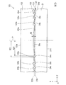
図7は、本実施形態の表示装置310を示す概略構成図である。
本実施形態の表示装置310は、図7に示すように、第1画像形成装置330aと、第2画像形成装置330bと、光学素子320と、を備える。第1画像形成装置330a及び第2画像形成装置330bは、特許請求の範囲の画像形成装置に相当する。
FIG. 7 is a schematic configuration diagram showing the display device 310 of the present embodiment.
As shown in FIG. 7, the display device 310 of the present embodiment includes a first image forming device 330 a, a second image forming device 330 b, and an optical element 320. The first image forming apparatus 330a and the second image forming apparatus 330b correspond to the image forming apparatuses recited in the claims.

第1画像形成装置330a及び第2画像形成装置330bは、例えば、第1実施形態の画像形成装置30と同様の構成を有している。第1画像形成装置330aは、光学素子320に向けて画像光Laを射出する。第2画像形成装置330bは、光学素子320に向けて画像光Lbを射出する。第1画像形成装置330a及び第2画像形成装置330bは、光学素子320に形成されたフレネルレンズ構造の焦点よりも、光学素子320に近い位置に配置されている。光学素子320に対する画像光Laの主光線の角度と、光学素子320に対する画像光Lbの主光線の角度とは、それぞれ異なる。   For example, the first image forming apparatus 330a and the second image forming apparatus 330b have the same configuration as the image forming apparatus 30 of the first embodiment. The first image forming apparatus 330 a emits image light La toward the optical element 320. The second image forming apparatus 330 b emits image light Lb toward the optical element 320. The first image forming apparatus 330 a and the second image forming apparatus 330 b are disposed at a position closer to the optical element 320 than the focal point of the Fresnel lens structure formed on the optical element 320. The angle of the principal ray of the image light La with respect to the optical element 320 is different from the angle of the principal ray of the image light Lb with respect to the optical element 320.

光学素子320は、視認側光透過性部材321と、外部側光透過性部材322と、光透過層23と、を備える。視認側光透過性部材321は、特許請求の範囲の第1の光透過性部材に相当する。外部側光透過性部材222は、特許請求の範囲の第2の光透過性部材に相当する。
視認側光透過性部材321は、視認面321aが曲面であることを除いて、第1実施形態の視認側光透過性部材21と同様である。外部側光透過性部材322は、外部側面322aが曲面であることを除いて、第1実施形態の外部側光透過性部材22と同様である。
The optical element 320 includes a viewing side light transmissive member 321, an external side light transmissive member 322, and a light transmissive layer 23. The viewing-side light transmissive member 321 corresponds to the first light transmissive member in the claims. The external light transmissive member 222 corresponds to the second light transmissive member in the claims.
The viewing side light transmissive member 321 is the same as the viewing side light transmissive member 21 of the first embodiment except that the viewing surface 321a is a curved surface. The external light transmissive member 322 is the same as the external light transmissive member 22 of the first embodiment except that the external side surface 322a is a curved surface.

視認面321a及び外部側面322aは、曲面部を持つ。具体的には、視認面321aは、外部側(+Y側)に凹となる凹曲面であり、外部側面322aは、外部側(+Y側)に凸となる凸曲面である。視認面321aの曲率と外部側面322aの曲率とは互いに同じであり、かつ、視認側反射部24の複数の凸部に形成された傾斜面の曲率及び外部側反射部25の複数の凹部に形成された傾斜面の曲率のいずれとも異なる。また、視認側反射部24の曲率は外部側反射部25の曲率と等しい。   The viewing surface 321a and the outer side surface 322a have a curved surface portion. Specifically, the viewing surface 321a is a concave curved surface that is concave on the outer side (+ Y side), and the outer side surface 322a is a convex curved surface that is convex on the outer side (+ Y side). The curvature of the viewing surface 321a and the curvature of the outer side surface 322a are the same, and the curvature of the inclined surface formed on the plurality of projections of the viewing-side reflection unit 24 and the plurality of recesses of the outer-side reflection unit 25 are formed. It differs from any of the curvatures of the inclined surfaces. Further, the curvature of the viewing-side reflection unit 24 is equal to the curvature of the external-side reflection unit 25.

そのため、視認側光透過性部材321側(−Y側)から外部側光透過性部材322側(+Y側)へ向かって進行する画像光Laと画像光Lbとに対する視認側反射部24の偏向作用及び外部側反射部25の偏向作用は、画像光Laと画像光Lbとに対する視認面321aの偏向作用及び外部側面322aの偏向作用のいずれとも異なる。
なお、視認面321aは、特許請求の範囲の第1面、及び曲面部に相当する。外部側面322aは、特許請求の範囲の第3面、及び曲面部に相当する。
Therefore, the deflection action of the viewing-side reflecting unit 24 with respect to the image light La and the image light Lb traveling from the viewing-side light transmissive member 321 side (−Y side) toward the external-side light transmissive member 322 side (+ Y side). The deflection action of the external reflecting section 25 is different from both the deflection action of the viewing surface 321a and the deflection action of the external side surface 322a with respect to the image light La and the image light Lb.
The visual recognition surface 321a corresponds to the first surface and the curved surface portion of the claims. The external side surface 322a corresponds to the third surface and the curved surface portion of the claims.

視認面321aの曲率は、第1画像形成装置330aから射出された画像光Laの反射光が観測者Mの眼に入射するように設計されている。また、視認側反射部24の曲率は、第2画像形成装置330bから射出された画像光Lbの反射光が観測者Mの眼に入射するように設計されている。これにより、観測者Mは、画像光Laの虚像と、画像光Lbの虚像と、外部の景色と、を同時に視認できる。   The curvature of the viewing surface 321a is designed so that the reflected light of the image light La emitted from the first image forming apparatus 330a enters the eye of the observer M. Further, the curvature of the viewing-side reflection unit 24 is designed so that the reflected light of the image light Lb emitted from the second image forming apparatus 330b is incident on the eyes of the observer M. Thereby, the observer M can visually recognize the virtual image of the image light La, the virtual image of the image light Lb, and the external scenery at the same time.

なお、図7においては、画像光Laと画像光Lbとのうち観測者Mの眼に入る光のみを図示しているが、実際には画像光Laの一部は視認側反射部24で反射され、画像光Lbの一部は視認面321aで反射される。しかし、視認側反射部24の曲率は、視認側反射部24で反射される画像光Laが観測者Mの眼に入射しないように設計され、視認面321aの曲率は、視認面321aで反射される画像光Lbが観測者Mの眼に入射しないように設計されている。   In FIG. 7, only the light that enters the eyes of the observer M among the image light La and the image light Lb is illustrated, but in practice, a part of the image light La is reflected by the viewing-side reflection unit 24. Then, a part of the image light Lb is reflected by the viewing surface 321a. However, the curvature of the viewing side reflection unit 24 is designed so that the image light La reflected by the viewing side reflection unit 24 does not enter the eyes of the observer M, and the curvature of the viewing surface 321a is reflected by the viewing surface 321a. The image light Lb is designed not to enter the eyes of the observer M.

本実施形態によれば、視認面321aの曲率及び外部側面322aの曲率が、視認側反射部24の複数の凸部に形成された傾斜面の曲率及び外部側反射部25の複数の凹部に形成された傾斜面の曲率のいずれとも異なる。そのため、視認面321aで反射される光の角度及び外部側面322aで反射される光の角度は、視認側反射部24で反射される光の角度と外部側反射部25で反射される光の角度のいずれとも異なる。これにより、光学素子320に対する入射角度がそれぞれ異なる画像光Laの一部と画像光Lbの一部とを観測者Mに向かって反射させることができる。したがって、本実施形態によれば、観測者Mは、異なる位置に配置された2つの画像形成装置から射出された画像光を重ね合わせた画像を視認できる。   According to the present embodiment, the curvature of the viewing surface 321a and the curvature of the outer side surface 322a are formed in the curvature of the inclined surface formed on the plurality of convex portions of the viewing side reflecting portion 24 and the plurality of concave portions of the outer side reflecting portion 25. It differs from any of the curvatures of the inclined surfaces. Therefore, the angle of the light reflected by the viewing surface 321a and the angle of the light reflected by the external side surface 322a are the angles of the light reflected by the viewing side reflection unit 24 and the light reflected by the external side reflection unit 25, respectively. It is different from any of. Thereby, part of the image light La and part of the image light Lb having different incident angles with respect to the optical element 320 can be reflected toward the observer M. Therefore, according to the present embodiment, the observer M can visually recognize an image obtained by superimposing image lights emitted from two image forming apparatuses arranged at different positions.

なお、本実施形態においては、視認面321aと外部側面322aとのうち、いずれか一方のみが曲面である構成としてもよい。また、視認面321aの曲率と、外部側面322aの曲率とは、異なっていてもよい。   In the present embodiment, only one of the viewing surface 321a and the outer side surface 322a may be a curved surface. Further, the curvature of the viewing surface 321a and the curvature of the outer side surface 322a may be different.

また、上記説明においては、視認面321aが曲面である場合、すなわち、視認面321aの全体が曲面部に相当する場合について示したが、これに限られない。本実施形態においては、視認面321aの一部に上記の曲面部が設けられる構成としてもよい。外部側面322aについても同様である。   Moreover, in the said description, although the case where the visual recognition surface 321a was a curved surface, ie, the case where the whole visual recognition surface 321a corresponded to a curved surface part was shown, it is not restricted to this. In this embodiment, it is good also as a structure by which said curved surface part is provided in a part of visual recognition surface 321a. The same applies to the external side surface 322a.

(第3実施形態)
第3実施形態は、第1実施形態に対して、光学素子の反射部にフレネルレンズ構造が形成されていない点において異なる。
なお、以下の説明において、上記実施形態と同様の構成については、適宜同一の符号を付すことにより、説明を省略する場合がある。
(Third embodiment)
The third embodiment is different from the first embodiment in that a Fresnel lens structure is not formed in the reflection portion of the optical element.
In the following description, the same components as those in the above embodiment may be denoted by the same reference numerals as appropriate, and the description may be omitted.

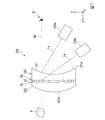
図8は、本実施形態の表示装置410を示す概略構成図である。図9は、本実施形態の光学素子420を示す斜視図である。
本実施形態の表示装置410は、図8に示すように、画像形成装置430と、光学素子420と、を備える。
FIG. 8 is a schematic configuration diagram showing the display device 410 of the present embodiment. FIG. 9 is a perspective view showing the optical element 420 of the present embodiment.
As shown in FIG. 8, the display device 410 of the present embodiment includes an image forming device 430 and an optical element 420.

画像形成装置430は、画像形成部431と、レンズ432と、を備える。
画像形成部431の構成は、例えば、第1実施形態の画像形成装置30と同様の構成である。画像形成部431は、画像光Lcを射出する。画像光Lcは、レンズ432を介して、光学素子420に向かって射出される。
The image forming apparatus 430 includes an image forming unit 431 and a lens 432.
The configuration of the image forming unit 431 is the same as that of the image forming apparatus 30 of the first embodiment, for example. The image forming unit 431 emits image light Lc. The image light Lc is emitted toward the optical element 420 through the lens 432.

レンズ432は、焦点が光学素子420よりも遠くに位置するように配置される。言い換えると、光学素子420は、レンズ432の焦点よりもレンズ432側に配置される。レンズ432によって画像光Lcが集光され、虚像Nが形成される。   The lens 432 is disposed so that the focal point is located farther than the optical element 420. In other words, the optical element 420 is disposed closer to the lens 432 than the focal point of the lens 432. The image light Lc is collected by the lens 432 and a virtual image N is formed.

光学素子420は、視認側光透過性部材421と、外部側光透過性部材422と、光透過層423と、を備える。光透過層423は、第1実施形態の光透過層23と同様である。視認側光透過性部材421は、特許請求の範囲の第1の光透過性部材に相当する。外部側光透過性部材422は、特許請求の範囲の第2の光透過性部材に相当する。   The optical element 420 includes a viewing side light transmissive member 421, an external side light transmissive member 422, and a light transmissive layer 423. The light transmission layer 423 is the same as the light transmission layer 23 of the first embodiment. The viewing-side light transmissive member 421 corresponds to the first light transmissive member in the claims. The external light transmissive member 422 corresponds to a second light transmissive member in the claims.

視認側光透過性部材421は、図8及び図9に示すように、視認面421aと、形成面421bと、視認側反射部424と、を備える。視認面421aは、特許請求の範囲の第1の面に相当する。形成面421bは、特許請求の範囲の第2の面に相当する。視認側反射部424は、特許請求の範囲の第1の反射部に相当する。   As shown in FIGS. 8 and 9, the viewing-side light transmissive member 421 includes a viewing surface 421 a, a forming surface 421 b, and a viewing-side reflecting portion 424. The viewing surface 421a corresponds to the first surface of the claims. The formation surface 421b corresponds to the second surface of the claims. The visual recognition side reflection part 424 is equivalent to the 1st reflection part of a claim.

視認面421aは、第1実施形態の視認面21aと同様である。
形成面421bは、視認面421aと対向する面である。形成面421bには、視認側反射部424が設けられている。
The viewing surface 421a is the same as the viewing surface 21a of the first embodiment.
The formation surface 421b is a surface facing the viewing surface 421a. On the forming surface 421b, a viewing-side reflecting portion 424 is provided.

視認側反射部424は、複数の凸部424aを含む。
凸部424aは、傾斜面426a(第1の傾斜面)と、傾斜面426b(第1の接続面)と、を備える。本実施形態において、凸部424aの断面(YZ断面)形状は、三角形状である。複数の凸部424aは、一方向(X軸方向)に延びて形成されている。複数の凸部424aは、鉛直方向(Z軸方向)に並んで、ストライプ状に配置されている。
The viewing side reflection part 424 includes a plurality of convex parts 424a.
The convex portion 424a includes an inclined surface 426a (first inclined surface) and an inclined surface 426b (first connection surface). In the present embodiment, the cross section (YZ cross section) of the convex portion 424a has a triangular shape. The plurality of convex portions 424a are formed to extend in one direction (X-axis direction). The plurality of convex portions 424a are arranged in stripes in the vertical direction (Z-axis direction).

傾斜面426a及び傾斜面426bは、形成面421bに対して傾いた平面である。形成面421bに対する傾斜面426aの傾きは、形成面421bに対する傾斜面426bの傾きより小さい。本実施形態においては、画像形成装置430から射出された画像光Lcは、傾斜面426aに入射される。   The inclined surface 426a and the inclined surface 426b are planes inclined with respect to the forming surface 421b. The inclination of the inclined surface 426a with respect to the forming surface 421b is smaller than the inclination of the inclined surface 426b with respect to the forming surface 421b. In the present embodiment, the image light Lc emitted from the image forming apparatus 430 is incident on the inclined surface 426a.

外部側光透過性部材422は、外部側面422aと、形成面422bと、外部側反射部425と、を備える。外部側面422aは、特許請求の範囲の第3の面に相当する。形成面422bは、特許請求の範囲の第4の面に相当する。外部側反射部425は、特許請求の範囲の第2の反射部に相当する。   The external light transmissive member 422 includes an external side surface 422a, a formation surface 422b, and an external reflection portion 425. The external side surface 422a corresponds to the third surface of the claims. The formation surface 422b corresponds to a fourth surface in the claims. The external reflection part 425 corresponds to the second reflection part in the claims.

外部側面422aは、第1実施形態の外部側面22aと同様である。
形成面422bは、外部側面422aと対向する面である。形成面422bには、外部側反射部425が設けられている。
The external side surface 422a is the same as the external side surface 22a of the first embodiment.
The formation surface 422b is a surface facing the outer side surface 422a. An external reflecting portion 425 is provided on the formation surface 422b.

外部側反射部425の形成面422bには、複数の凹部425aが設けられている。凹部425aの形状は、それに対応する凸部424aの形状に倣う。
凹部425aは、傾斜面427a(第2の傾斜面)と、傾斜面427b(第2の接続面)と、を備える。本実施形態において、凹部425aの断面(YZ断面)形状は、三角形状である。複数の凹部425aは、一方向(X軸方向)に延びて形成されている。複数の凹部425aは、鉛直方向(Z軸方向)に並んで、ストライプ状に配置されている。
A plurality of recesses 425 a are provided on the formation surface 422 b of the external reflection part 425. The shape of the concave portion 425a follows the shape of the corresponding convex portion 424a.
The recess 425a includes an inclined surface 427a (second inclined surface) and an inclined surface 427b (second connection surface). In the present embodiment, the cross section (YZ cross section) of the recess 425a has a triangular shape. The plurality of recesses 425a are formed extending in one direction (X-axis direction). The plurality of recesses 425a are arranged in stripes in the vertical direction (Z-axis direction).

傾斜面427a及び傾斜面427bは、形成面422bに対して傾いた平面である。形成面422bに対する傾斜面427aの傾きは、形成面422bに対する傾斜面427bの傾きより小さい。本実施形態においては、傾斜面427aに画像形成装置430から射出された画像光Lcが入射される。   The inclined surface 427a and the inclined surface 427b are planes inclined with respect to the formation surface 422b. The inclination of the inclined surface 427a with respect to the forming surface 422b is smaller than the inclination of the inclined surface 427b with respect to the forming surface 422b. In the present embodiment, the image light Lc emitted from the image forming apparatus 430 is incident on the inclined surface 427a.

複数の凸部424aと複数の凹部425aとは、かみ合うように設けられている。凸部424aの傾斜面426aと凹部425aの傾斜面427aとは、互いに平行である。凸部424aの傾斜面426bと凹部425aの傾斜面427bとは、互いに平行である。   The plurality of convex portions 424a and the plurality of concave portions 425a are provided so as to mesh with each other. The inclined surface 426a of the convex portion 424a and the inclined surface 427a of the concave portion 425a are parallel to each other. The inclined surface 426b of the convex portion 424a and the inclined surface 427b of the concave portion 425a are parallel to each other.

本実施形態においては、画像形成装置430から射出された画像光Lcの一部は、視認側反射部424の傾斜面426aと外部側反射部425の傾斜面427aとのうちのいずれか一方において反射され、観測者Mの眼に入射する。言い換えると、視認側反射部424の凸部424a及び外部側反射部425の凹部425aは、視認側光透過性部材421側(−Y側)から外部側光透過性部材422側(+Y側)に向かって進行する画像光Lcを観測者Mに向かって反射する。   In the present embodiment, a part of the image light Lc emitted from the image forming apparatus 430 is reflected on any one of the inclined surface 426a of the viewing-side reflecting unit 424 and the inclined surface 427a of the external-side reflecting unit 425. And enters the eyes of the observer M. In other words, the convex portion 424a of the viewing-side reflective portion 424 and the concave portion 425a of the external-side reflecting portion 425 are changed from the viewing-side light transmissive member 421 side (−Y side) to the external side light transmissive member 422 side (+ Y side). The image light Lc traveling toward the viewer M is reflected toward the observer M.

一方、外部側(+Y側)から光学素子420に入射する光の一部は透過され、観測者Mの眼に入射される。これにより、観測者Mは、外部の景色と画像形成装置430によって形成された画像とを同時に視認できる。   On the other hand, a part of the light incident on the optical element 420 from the outside (+ Y side) is transmitted and is incident on the eye of the observer M. As a result, the observer M can visually recognize the external scenery and the image formed by the image forming apparatus 430 at the same time.

なお、視認側反射部424の凸部424aまたは外部側反射部425の凹部425aによって画像光Lcが反射される方向は、特許請求の範囲の第1の方向に相当する。   Note that the direction in which the image light Lc is reflected by the convex portion 424a of the viewing-side reflecting portion 424 or the concave portion 425a of the external-side reflecting portion 425 corresponds to the first direction of the claims.

本実施形態によれば、凸部424aの傾斜面426aと凹部425aの傾斜面427aとは互いに平行であるため、光学素子420を透過する光は、入射した方向と平行な方向に射出される。これにより、観測者Mによって視認される外部の景色が歪むことを抑制できる。   According to the present embodiment, since the inclined surface 426a of the convex portion 424a and the inclined surface 427a of the concave portion 425a are parallel to each other, the light transmitted through the optical element 420 is emitted in a direction parallel to the incident direction. Thereby, it can suppress that the external scenery visually recognized by the observer M is distorted.

また、本実施形態においては、画像光Lcが反射される複数の傾斜面426aは、互いに傾斜面426bによって接続されている。そのため、隣り合う傾斜面426a同士の間には段差が生じている。これにより、観測者Mに視認される画像が、段差の部分で不連続となる場合がある。これに対して、観測者Mと虚像Nとの距離W4を、段差の大きさ、すなわち、傾斜面426bの視線Ma方向(Y軸方向)の寸法に対して十分に大きく設定することで、観測者Mに視認される画像に対する段差の影響を効果的に低減できる。距離W4を調整する方法としては、例えば、レンズ432の焦点距離を変化させる方法や、光学素子420に対するレンズ432の設けられる位置を変化させる方法が挙げられる。なお、傾斜面427aについても同様である。   In the present embodiment, the plurality of inclined surfaces 426a on which the image light Lc is reflected are connected to each other by the inclined surfaces 426b. Therefore, a step is generated between the adjacent inclined surfaces 426a. Thereby, the image visually recognized by the observer M may become discontinuous at the level difference part. On the other hand, the distance W4 between the observer M and the virtual image N is set to be sufficiently larger than the size of the step, that is, the dimension of the inclined surface 426b in the line of sight Ma direction (Y-axis direction). The effect of the step on the image visually recognized by the person M can be effectively reduced. Examples of the method of adjusting the distance W4 include a method of changing the focal length of the lens 432 and a method of changing the position where the lens 432 is provided with respect to the optical element 420. The same applies to the inclined surface 427a.

なお、本実施形態においては、以下の構成を採用してもよい。   In the present embodiment, the following configuration may be employed.

傾斜面426bと傾斜面427bとの少なくとも一方に光吸収部材を設けてもよい。これにより、迷光を低減できる。また、傾斜面426bを形成面421bに直交する垂直面としてもよい。また、傾斜面427bを、形成面422bに直交する垂直面としてもよい。   A light absorbing member may be provided on at least one of the inclined surface 426b and the inclined surface 427b. Thereby, stray light can be reduced. Alternatively, the inclined surface 426b may be a vertical surface orthogonal to the formation surface 421b. The inclined surface 427b may be a vertical surface orthogonal to the formation surface 422b.

また、本実施形態においては、レンズ432は設けられていなくてもよい。この場合においては、虚像Nは形成されず、観測者Mの眼には、光学素子420によって反射されたミラー像が映る。   In the present embodiment, the lens 432 may not be provided. In this case, the virtual image N is not formed, and the mirror image reflected by the optical element 420 is reflected in the eyes of the observer M.

また、上記説明においては、画像形成装置430が1つである構成としたが、これに限られない。本実施形態においては、例えば、図10に示す表示装置510のように、2つの画像形成装置が設けられる構成としてもよい。   In the above description, the number of image forming apparatuses 430 is one, but the present invention is not limited to this. In the present embodiment, for example, a configuration in which two image forming apparatuses are provided as in the display apparatus 510 illustrated in FIG. 10 may be employed.

図10は、表示装置510を示す概略構成図である。図10においては、図8と異なり、鉛直方向上方側(+Z側)から視た場合を示している。
表示装置510は、図10に示すように、右目用画像形成装置530aと、左目用画像形成装置530bと、光学素子520と、を備える。右目用画像形成装置530a及び左目用画像形成装置530bは、特許請求の範囲の画像形成装置に相当する。
FIG. 10 is a schematic configuration diagram showing the display device 510. In FIG. 10, unlike FIG. 8, the case is seen from the upper side in the vertical direction (+ Z side).
As shown in FIG. 10, the display device 510 includes a right-eye image forming device 530a, a left-eye image forming device 530b, and an optical element 520. The image forming apparatus for right eye 530a and the image forming apparatus for left eye 530b correspond to the image forming apparatus in the claims.

右目用画像形成装置530aは、画像形成部531aと、レンズ532aと、を備える。左目用画像形成装置530bは、画像形成部531bと、レンズ532bと、を備える。画像形成部531a及び画像形成部531bは、画像形成部431と同様である。レンズ532a及びレンズ532bは、レンズ432と同様である。   The right-eye image forming apparatus 530a includes an image forming unit 531a and a lens 532a. The left-eye image forming apparatus 530b includes an image forming unit 531b and a lens 532b. The image forming unit 531a and the image forming unit 531b are the same as the image forming unit 431. The lens 532 a and the lens 532 b are the same as the lens 432.

光学素子520は、視認側光透過性部材521と、外部側光透過性部材522と、光透過層523と、を備える。図10において、光学素子520は、図8における光学素子420に対して、視線Ma方向(Y軸方向)回りに90°回転した状態で配置されている。すなわち、凸部524aの延びる方向が、鉛直方向(Z軸方向)となっている。視認側光透過性部材521は、特許請求の範囲の第1の光透過性部材に相当する。外部側光透過性部材522は、特許請求の範囲の第2の光透過性部材に相当する。   The optical element 520 includes a viewing side light transmissive member 521, an external side light transmissive member 522, and a light transmissive layer 523. In FIG. 10, the optical element 520 is arranged in a state of being rotated 90 ° around the line of sight Ma direction (Y-axis direction) with respect to the optical element 420 in FIG. That is, the extending direction of the convex portion 524a is the vertical direction (Z-axis direction). The viewing-side light transmissive member 521 corresponds to the first light transmissive member in the claims. The external light transmissive member 522 corresponds to the second light transmissive member in the claims.

視認側光透過性部材521は、視認側反射部524における凸部524aの傾斜面526aの傾斜角度及び傾斜面526bの傾斜角度以外の点においては、視認側光透過性部材421と同様である。外部側光透過性部材522は、外部側反射部525における凹部525aの傾斜面527aの傾斜角度及び傾斜面527bの傾斜角度以外の点においては、外部側光透過性部材422と同様である。
なお、視認側反射部524は、特許請求の範囲における第1の反射部に相当する。外部側反射部525は、特許請求の範囲における第2の反射部に相当する。傾斜面526aは、特許請求の範囲における第1の傾斜面に相当する。傾斜面527aは、特許請求の範囲における第2の傾斜面に相当する。
The viewing-side light transmissive member 521 is the same as the viewing-side light transmissive member 421 except for the inclination angle of the inclined surface 526a of the convex portion 524a and the inclination angle of the inclined surface 526b in the viewing-side reflecting portion 524. The external light transmissive member 522 is the same as the external light transmissive member 422 except for the inclination angle of the inclined surface 527a of the recess 525a and the inclination angle of the inclined surface 527b in the external reflection portion 525.
In addition, the visual recognition side reflection part 524 is equivalent to the 1st reflection part in a claim. The external reflection part 525 corresponds to the second reflection part in the claims. The inclined surface 526a corresponds to the first inclined surface in the claims. The inclined surface 527a corresponds to the second inclined surface in the claims.

凸部524aの断面(XY断面)形状は、二等辺三角形状である。凸部524aにおいて、形成面521bに対する傾斜面526aの傾斜角度と、形成面521bに対する傾斜面526bの傾斜角度とは、互いに同じである。
凹部525aの断面(XY断面)形状は、二等辺三角形状である。凹部525aにおいて、形成面522bに対する傾斜面527aの傾斜角度と、形成面522bに対する傾斜面527bの傾斜角度とは、互いに同じである。
なお、形成面521bは、特許請求の範囲の第2の面に相当する。形成面522bは、特許請求の範囲の第4の面に相当する。
The cross section (XY cross section) of the convex portion 524a is an isosceles triangle. In the convex portion 524a, the inclination angle of the inclined surface 526a with respect to the forming surface 521b and the inclination angle of the inclined surface 526b with respect to the forming surface 521b are the same.
The cross section (XY cross section) of the recess 525a is an isosceles triangle. In the recess 525a, the inclination angle of the inclined surface 527a with respect to the formation surface 522b and the inclination angle of the inclination surface 527b with respect to the formation surface 522b are the same.
The formation surface 521b corresponds to the second surface of the claims. The formation surface 522b corresponds to the fourth surface of the claims.

右目用画像形成装置530aから射出される画像光Ldのうち、傾斜面526aで反射した光と傾斜面527aで反射した光とは、観測者Mの右目REに入射する。   Of the image light Ld emitted from the right-eye image forming apparatus 530a, the light reflected by the inclined surface 526a and the light reflected by the inclined surface 527a enter the right eye RE of the observer M.

一方、左目用画像形成装置530bから射出される画像光Leのうち、傾斜面526bで反射した光と傾斜面527bで反射した光とは、観測者Mの左目LEに入射する。   On the other hand, among the image light Le emitted from the image forming apparatus for left eye 530b, the light reflected by the inclined surface 526b and the light reflected by the inclined surface 527b are incident on the left eye LE of the observer M.

これにより、観測者Mの右目REには、右目用画像形成装置530aから射出された画像光Ldによって形成される虚像NRが視認され、観測者Mの左目LEには、左目用画像形成装置530bから射出された画像光Leによって形成された虚像NLが視認される。また、同時に、観測者Mの両目には、外部側面522aから入射して、視認面521aから射出された外部からの光が入射される。
なお、視認面521aは、特許請求の範囲の第1の面に相当する。外部側面522aは、特許請求の範囲の第3の面に相当する。
As a result, the virtual image NR formed by the image light Ld emitted from the right eye image forming apparatus 530a is visually recognized in the right eye RE of the observer M, and the left eye image forming apparatus 530b is observed in the left eye LE of the observer M. The virtual image NL formed by the image light Le emitted from is visually recognized. At the same time, both eyes of the observer M are incident with light from the outside that is incident from the external side surface 522a and is emitted from the viewing surface 521a.
The viewing surface 521a corresponds to the first surface of the claims. The external side surface 522a corresponds to the third surface of the claims.

この構成によれば、右目用の画像と左目用の画像をそれぞれ観測者Mの右目REと左目LEとに入射させることができるため、観測者Mに3D画像を視認させることが可能である。   According to this configuration, the image for the right eye and the image for the left eye can be incident on the right eye RE and the left eye LE of the observer M, respectively, so that the observer M can visually recognize the 3D image.

(第4実施形態)
第4実施形態においては、上記第1実施形態から第3実施形態に示した表示装置が乗用自動車に搭載された例を示す。
なお、以下の説明において、上記実施形態と同様の構成については、適宜同一の符号を付すことにより、説明を省略する場合がある。
(Fourth embodiment)
The fourth embodiment shows an example in which the display device shown in the first to third embodiments is mounted on a passenger car.
In the following description, the same components as those in the above embodiment may be denoted by the same reference numerals as appropriate, and the description may be omitted.

図11は、表示装置が搭載された車両70を示す概略構成図である。
本実施形態の車両70は、図11に示すように、表示装置1100と、フロントウィンドウ72と、ダッシュボード73と、を備える。車両70は、例えば、セダンタイプの乗用自動車である。
FIG. 11 is a schematic configuration diagram showing a vehicle 70 on which a display device is mounted.
As shown in FIG. 11, the vehicle 70 according to the present embodiment includes a display device 1100, a front window 72, and a dashboard 73. The vehicle 70 is, for example, a sedan type passenger car.

表示装置1100は、例えば、第1実施形態の表示装置10と同様の構成である。表示装置1100は、光学素子1000と、画像形成装置30と、を備える。
光学素子1000は、フロントウィンドウ72に設けられている。光学素子1000は、図1に示す光学素子20と同様の構成である。観測者、すなわち、図11においては乗員Cの視線は、光学素子1000の視認面の法線に対して傾いている。
画像形成装置30は、図11に示すように、ダッシュボード73の内部に収納されている。
The display device 1100 has the same configuration as the display device 10 of the first embodiment, for example. The display device 1100 includes an optical element 1000 and the image forming apparatus 30.
The optical element 1000 is provided on the front window 72. The optical element 1000 has the same configuration as the optical element 20 shown in FIG. In FIG. 11, the line of sight of the occupant C is tilted with respect to the normal line of the viewing surface of the optical element 1000.
The image forming apparatus 30 is housed inside a dashboard 73 as shown in FIG.

ダッシュボード73には、画像光Lを透過するための開口部73Hが設けられている。画像光Lは、開口部73Hを介して、光学素子1000に向けて射出される。光学素子1000に入射した画像光Lの一部は、乗員Cに向けて反射される。これにより、画像光Lによって形成された虚像Nが車両70の乗員Cに視認される。   The dashboard 73 is provided with an opening 73H for transmitting the image light L. The image light L is emitted toward the optical element 1000 through the opening 73H. A part of the image light L incident on the optical element 1000 is reflected toward the passenger C. As a result, the virtual image N formed by the image light L is visually recognized by the occupant C of the vehicle 70.

また、外部からの光の一部は、光学素子1000を透過して乗員Cに視認される。したがって、乗員Cは、画像形成装置30によって形成された画像と外部の景色とを同時に視認できる。   Further, part of the light from the outside passes through the optical element 1000 and is visually recognized by the occupant C. Therefore, the occupant C can visually recognize the image formed by the image forming apparatus 30 and the external scenery at the same time.

本実施形態によれば、上述した実施形態と同様に、外部の景色が歪むことを抑制しつつ、外部の景色と画像形成装置30によって形成された画像とを同時に視認できる。   According to the present embodiment, as in the above-described embodiment, the external scenery and the image formed by the image forming apparatus 30 can be simultaneously viewed while suppressing the external scenery from being distorted.

なお、本実施形態において表示装置1100は、第2実施形態及び第3実施形態の表示装置と同様の構成であってもよい。   In the present embodiment, the display device 1100 may have the same configuration as the display devices of the second embodiment and the third embodiment.

なお、上記の第1実施形態から第4実施形態においては、本発明の表示装置をヘッドアップディスプレイに適用した例について説明したが、これに限られず、例えば、本発明はヘッドマウントディスプレイ等にも適用できる。   In the first to fourth embodiments, the example in which the display device of the present invention is applied to a head-up display has been described. However, the present invention is not limited to this example. Applicable.

10,310,410,510,1100…表示装置、20,120,220,320,420,520,1000…光学素子、21…視認側光透過性部材(第1の光透過性部材)、21a,421a,521a…視認面(第1の面)、21b,421b,521b…形成面(第2の面)、22,122,222,322,422,522…外部側光透過性部材(第2の光透過性部材)、22a,122a,222a,422a,522a…外部側面(第3の面)、22b,122b,222b,422b,522b…形成面(第4の面)、23,123,223,423,523…光透過層、24,424,524…視認側反射部(第1の反射部)、24a…中央凸部(凸部)、24b…円環状凸部(凸部,第1の凸部)、24c…円環状凸部(凸部,第2の凸部)、24d…円環状凸部(凸部)、25,125,225,425,525…外部側反射部(第2の反射部)、25a,125a,225a…中央凹部(凹部)、25b,125b,225b…円環状凹部(凹部,第1の凹部)、25c,125c,225c…円環状凹部(凹部,第2の凹部)、25d,125d,225d…円環状凹部(凹部)、26a,26b,26c,26d,426a,526a,526b…傾斜面(第1の傾斜面)、27a,27b,27c,27d,427a,527a,527b…傾斜面(第2の傾斜面)、28b…バックカット面(第1の接続面)、29b,129b,229b…バックカット面(第2の接続面)、30,430…画像形成装置、40b…光吸収部材(第1の光吸収部材)、41b…光吸収部材(第2の光吸収部材)、321a…視認面(第1の面,曲面部)、322a…外部側面(第3の面,曲面部)、330a…第1画像形成装置(画像形成装置)、330b…第2画像形成装置(画像形成装置)、424a,524a…凸部、425a,525a…凹部、426b…傾斜面(第1の接続面)、427b…傾斜面(第2の接続面)、530a…右目用画像形成装置(画像形成装置)、530b…左目用画像形成装置(画像形成装置)、L,La,Lb,Lc,Ld,Le…画像光   10, 310, 410, 510, 1100 ... display device, 20, 120, 220, 320, 420, 520, 1000 ... optical element, 21 ... viewing side light transmitting member (first light transmitting member), 21a, 421a, 521a ... viewing surface (first surface), 21b, 421b, 521b ... forming surface (second surface), 22, 122, 222, 322, 422, 522 ... external light transmitting member (second Light transmitting member), 22a, 122a, 222a, 422a, 522a ... external side surface (third surface), 22b, 122b, 222b, 422b, 522b ... formation surface (fourth surface), 23, 123, 223 423, 523 ... Light transmission layer, 24, 424, 524 ... Viewing-side reflecting part (first reflecting part), 24a ... Central convex part (convex part), 24b ... Circular convex part (convex part, first convex part) Part), 24c ... Part (convex part, second convex part), 24d ... annular convex part (convex part), 25, 125, 225, 425, 525 ... external side reflective part (second reflective part), 25a, 125a, 225a ... central recess (recess), 25b, 125b, 225b ... annular recess (recess, first recess), 25c, 125c, 225c ... annular recess (recess, second recess), 25d, 125d, 225d ... circle Annular recesses (recesses), 26a, 26b, 26c, 26d, 426a, 526a, 526b ... inclined surfaces (first inclined surfaces), 27a, 27b, 27c, 27d, 427a, 527a, 527b ... inclined surfaces (second Inclined surface), 28b ... Back cut surface (first connection surface), 29b, 129b, 229b ... Back cut surface (second connection surface), 30, 430 ... Image forming apparatus, 40b ... Light absorbing member (first Light absorption Member), 41b ... light absorbing member (second light absorbing member), 321a ... viewing surface (first surface, curved surface portion), 322a ... external side surface (third surface, curved surface portion), 330a ... first image Forming device (image forming device), 330b ... second image forming device (image forming device), 424a, 524a ... convex portion, 425a, 525a ... concave portion, 426b ... inclined surface (first connecting surface), 427b ... inclined surface (Second connection surface) 530a ... right-eye image forming apparatus (image forming apparatus), 530b ... left-eye image forming apparatus (image forming apparatus), L, La, Lb, Lc, Ld, Le ... image light

Claims (9)

第1の面と、該第1の面と対向する第2の面と、該第2の面に設けられた複数の凸部を含む第1の反射部と、を備えた第1の光透過性部材と、
第3の面と、該第3の面と対向する第4の面と、該第4の面に設けられ、前記複数の凸部に倣う複数の凹部を含む第2の反射部と、を備えた第2の光透過性部材と、
前記第1の光透過性部材の屈折率及び前記第2の光透過性部材の屈折率と異なる屈折率を持つ光透過層と、
を有し、
前記複数の凸部の各々は、前記第2の面に対して傾いた第1の傾斜面を備え、
前記複数の凹部の各々は、前記第4の面に対して傾いた第2の傾斜面を備え、
前記複数の凸部が前記光透過層を介して前記複数の凹部とかみ合うように、前記第1の光透過性部材と前記第2の光透過性部材とが配置されていることを特徴とする光学素子。
1st light transmission provided with the 1st surface, the 2nd surface facing this 1st surface, and the 1st reflective part containing a plurality of convex parts provided in this 2nd surface Sex members;
A third surface, a fourth surface facing the third surface, and a second reflecting portion provided on the fourth surface and including a plurality of concave portions that follow the plurality of convex portions. A second light transmissive member;
A light transmissive layer having a refractive index different from that of the first light transmissive member and a refractive index of the second light transmissive member;
Have
Each of the plurality of convex portions includes a first inclined surface inclined with respect to the second surface,
Each of the plurality of recesses includes a second inclined surface inclined with respect to the fourth surface,
The first light transmissive member and the second light transmissive member are arranged so that the plurality of convex portions engage with the plurality of concave portions via the light transmissive layer. Optical element.
前記複数の凸部は、フレネルレンズ構造を構成する、請求項1に記載の光学素子。   The optical element according to claim 1, wherein the plurality of convex portions constitute a Fresnel lens structure. 前記複数の凸部は、三角形状の断面を持つ凸部を含む、請求項1に記載の光学素子。   The optical element according to claim 1, wherein the plurality of convex portions include convex portions having a triangular cross section. 前記複数の凸部はストライプ構造を構成し、前記第1の光透過性部材から前記第2の光透過性部材側へ向かって進行する光を第1の方向に反射する、請求項3に記載の光学素子。   The plurality of convex portions form a stripe structure, and reflect light traveling from the first light transmissive member toward the second light transmissive member in a first direction. Optical elements. 前記複数の凸部は、第1の凸部と、該第1の凸部に隣り合う第2の凸部と、該第1の凸部が備える前記第1の傾斜面を該第2の凸部が備える前記第1の傾斜面と接続する第1の接続面と、該第1の接続面に設けられた第1の光吸収部材と、を更に備える、請求項1から4のいずれか一項に記載の光学素子。   The plurality of convex portions include a first convex portion, a second convex portion adjacent to the first convex portion, and the first inclined surface included in the first convex portion. 5. The apparatus according to claim 1, further comprising: a first connection surface connected to the first inclined surface included in the section; and a first light absorbing member provided on the first connection surface. The optical element according to item. 前記複数の凹部は、第1の凹部と、該第1の凹部に隣り合う第2の凹部と、該第1の凹部が備える前記第2の傾斜面を該第2の凹部が備える前記第2の傾斜面と接続する第2の接続面と、該第2の接続面に設けられた第2の光吸収部材と、を更に備える、請求項1から5のいずれか一項に記載の光学素子。   The plurality of concave portions include a first concave portion, a second concave portion adjacent to the first concave portion, and the second inclined surface provided in the first concave portion. 6. The optical element according to claim 1, further comprising: a second connection surface that is connected to the inclined surface; and a second light absorbing member that is provided on the second connection surface. . 前記第1の面と前記第3の面とのうち少なくとも一方は曲面部を持ち、前記第1の光透過性部材側から前記第2の光透過性部材側へ向かって進行する光に対する前記第1の反射部の偏向作用は、該光に対する前記曲面部の偏向作用と異なる、請求項1から6のいずれか一項に記載の光学素子。   At least one of the first surface and the third surface has a curved portion, and the first surface with respect to light traveling from the first light transmissive member side toward the second light transmissive member side. The optical element according to any one of claims 1 to 6, wherein a deflecting action of one reflecting portion is different from a deflecting action of the curved surface portion with respect to the light. 前記光透過層は、金属からなる、請求項1から7のいずれか一項に記載の光学素子。   The optical element according to claim 1, wherein the light transmission layer is made of a metal. 画像光を射出する画像形成装置と、
前記画像光の光路上に設けられた請求項1から8のいずれか一項に記載の光学素子と、
を備えることを特徴とする表示装置。
An image forming apparatus for emitting image light;
The optical element according to any one of claims 1 to 8, provided on an optical path of the image light;
A display device comprising:
JP2014141309A 2014-07-09 2014-07-09 Optical element and display device Pending JP2016018103A (en)

Priority Applications (1)

Application Number Priority Date Filing Date Title
JP2014141309A JP2016018103A (en) 2014-07-09 2014-07-09 Optical element and display device

Applications Claiming Priority (1)

Application Number Priority Date Filing Date Title
JP2014141309A JP2016018103A (en) 2014-07-09 2014-07-09 Optical element and display device

Publications (1)

Publication Number Publication Date
JP2016018103A true JP2016018103A (en) 2016-02-01

Family

ID=55233358

Family Applications (1)

Application Number Title Priority Date Filing Date
JP2014141309A Pending JP2016018103A (en) 2014-07-09 2014-07-09 Optical element and display device

Country Status (1)

Country Link
JP (1) JP2016018103A (en)

Cited By (2)

* Cited by examiner, † Cited by third party
Publication number Priority date Publication date Assignee Title
JP2020024265A (en) * 2018-08-06 2020-02-13 大日本印刷株式会社 Reflection screen, laminated glass, and video display device
WO2024085430A1 (en) * 2022-10-19 2024-04-25 주식회사 세코닉스 Near-eye display micro-mirror film

Citations (5)

* Cited by examiner, † Cited by third party
Publication number Priority date Publication date Assignee Title
JPH11338056A (en) * 1998-05-22 1999-12-10 Nissho Giken Kk Video display device
JP2005084172A (en) * 2003-09-05 2005-03-31 Calsonic Kansei Corp Display unit for vehicle
JP2006301180A (en) * 2005-04-19 2006-11-02 Shimadzu Corp Display device
US20100046075A1 (en) * 2008-08-19 2010-02-25 Microvision, Inc. Embedded relay lens for head-up displays or the like
JP2011191715A (en) * 2010-03-17 2011-09-29 Toshiba Corp Optical element, display device, display method, and moving body

Patent Citations (5)

* Cited by examiner, † Cited by third party
Publication number Priority date Publication date Assignee Title
JPH11338056A (en) * 1998-05-22 1999-12-10 Nissho Giken Kk Video display device
JP2005084172A (en) * 2003-09-05 2005-03-31 Calsonic Kansei Corp Display unit for vehicle
JP2006301180A (en) * 2005-04-19 2006-11-02 Shimadzu Corp Display device
US20100046075A1 (en) * 2008-08-19 2010-02-25 Microvision, Inc. Embedded relay lens for head-up displays or the like
JP2011191715A (en) * 2010-03-17 2011-09-29 Toshiba Corp Optical element, display device, display method, and moving body

Cited By (3)

* Cited by examiner, † Cited by third party
Publication number Priority date Publication date Assignee Title
JP2020024265A (en) * 2018-08-06 2020-02-13 大日本印刷株式会社 Reflection screen, laminated glass, and video display device
JP7124535B2 (en) 2018-08-06 2022-08-24 大日本印刷株式会社 Reflective screen, laminated glass and image display device
WO2024085430A1 (en) * 2022-10-19 2024-04-25 주식회사 세코닉스 Near-eye display micro-mirror film

Similar Documents

Publication Publication Date Title
JP6875542B2 (en) Light guide plate and video display device
KR101196967B1 (en) Optical element, display device, display method and mobile object
US8929001B2 (en) Display device
JP5046049B2 (en) Image display device and method of manufacturing image display device
KR20170030594A (en) Light guide device and virtual image display apparatus
JP6432540B2 (en) Head-up display device
JP6601431B2 (en) Head-up display device
JP6503693B2 (en) Optical element, method of manufacturing optical element, optical device and display device
JP5499015B2 (en) OPTICAL ELEMENT, DISPLAY DEVICE, DISPLAY METHOD, AND MOBILE BODY
US20200183183A1 (en) Image display apparatus
JP2015133304A (en) Illumination lens, illumination unit, and head-up display device
JP2017211454A (en) Screen and image display device
JP5537337B2 (en) Display device and display method
CN112334814B (en) Image display device and projection optical system
US9164282B2 (en) Image-partitioned display device for virtual image
JP2016224110A (en) Optical coupling element
JP2016018103A (en) Optical element and display device
JP2016045385A (en) Translucent screen and head-up display device using the same
WO2017131185A1 (en) Head-up display device for vehicle
JP2014222260A (en) Optical element, display device, and method for manufacturing optical element
JP2018165743A (en) Light guide device and display device
JP2014215481A (en) Head-up display device
JP2014139596A (en) Directional reflection screen and image display device
CN112748572A (en) Virtual image display device and light guide member
WO2014041690A1 (en) Optical element and head-up display

Legal Events

Date Code Title Description
A621 Written request for application examination

Free format text: JAPANESE INTERMEDIATE CODE: A621

Effective date: 20170607

A977 Report on retrieval

Free format text: JAPANESE INTERMEDIATE CODE: A971007

Effective date: 20180307

A131 Notification of reasons for refusal

Free format text: JAPANESE INTERMEDIATE CODE: A131

Effective date: 20180417

A521 Request for written amendment filed

Free format text: JAPANESE INTERMEDIATE CODE: A523

Effective date: 20180618

RD03 Notification of appointment of power of attorney

Free format text: JAPANESE INTERMEDIATE CODE: A7423

Effective date: 20181026

A02 Decision of refusal

Free format text: JAPANESE INTERMEDIATE CODE: A02

Effective date: 20181204