JP6432540B2 - Head-up display device - Google Patents
Head-up display device Download PDFInfo
- Publication number
- JP6432540B2 JP6432540B2 JP2016027338A JP2016027338A JP6432540B2 JP 6432540 B2 JP6432540 B2 JP 6432540B2 JP 2016027338 A JP2016027338 A JP 2016027338A JP 2016027338 A JP2016027338 A JP 2016027338A JP 6432540 B2 JP6432540 B2 JP 6432540B2
- Authority
- JP
- Japan
- Prior art keywords
- plate
- refractive index
- light
- head
- display device
- Prior art date
- Legal status (The legal status is an assumption and is not a legal conclusion. Google has not performed a legal analysis and makes no representation as to the accuracy of the status listed.)
- Active
Links
- 230000003287 optical effect Effects 0.000 claims description 53
- 230000000007 visual effect Effects 0.000 claims description 12
- 230000001105 regulatory effect Effects 0.000 claims 2
- 230000000875 corresponding effect Effects 0.000 description 24
- 239000004973 liquid crystal related substance Substances 0.000 description 19
- 230000010287 polarization Effects 0.000 description 13
- 230000004048 modification Effects 0.000 description 8
- 238000012986 modification Methods 0.000 description 8
- 230000005540 biological transmission Effects 0.000 description 7
- 229920003002 synthetic resin Polymers 0.000 description 7
- 239000000057 synthetic resin Substances 0.000 description 7
- 230000000052 comparative effect Effects 0.000 description 5
- 239000011521 glass Substances 0.000 description 5
- 238000000034 method Methods 0.000 description 5
- 230000000694 effects Effects 0.000 description 4
- 238000004040 coloring Methods 0.000 description 3
- 239000000463 material Substances 0.000 description 3
- 239000011159 matrix material Substances 0.000 description 3
- 238000005096 rolling process Methods 0.000 description 3
- 238000010521 absorption reaction Methods 0.000 description 2
- 230000009471 action Effects 0.000 description 2
- XAGFODPZIPBFFR-UHFFFAOYSA-N aluminium Chemical compound [Al] XAGFODPZIPBFFR-UHFFFAOYSA-N 0.000 description 2
- 229910052782 aluminium Inorganic materials 0.000 description 2
- 230000008859 change Effects 0.000 description 2
- 238000000151 deposition Methods 0.000 description 2
- 238000010586 diagram Methods 0.000 description 2
- 238000004519 manufacturing process Methods 0.000 description 2
- 230000007246 mechanism Effects 0.000 description 2
- ZCYVEMRRCGMTRW-UHFFFAOYSA-N 7553-56-2 Chemical compound [I] ZCYVEMRRCGMTRW-UHFFFAOYSA-N 0.000 description 1
- 229920000178 Acrylic resin Polymers 0.000 description 1
- 239000004925 Acrylic resin Substances 0.000 description 1
- OAICVXFJPJFONN-UHFFFAOYSA-N Phosphorus Chemical compound [P] OAICVXFJPJFONN-UHFFFAOYSA-N 0.000 description 1
- 239000004372 Polyvinyl alcohol Substances 0.000 description 1
- 230000004308 accommodation Effects 0.000 description 1
- 238000005520 cutting process Methods 0.000 description 1
- 230000006866 deterioration Effects 0.000 description 1
- 210000000744 eyelid Anatomy 0.000 description 1
- 239000000446 fuel Substances 0.000 description 1
- PNDPGZBMCMUPRI-UHFFFAOYSA-N iodine Chemical compound II PNDPGZBMCMUPRI-UHFFFAOYSA-N 0.000 description 1
- 229910052740 iodine Inorganic materials 0.000 description 1
- 239000011630 iodine Substances 0.000 description 1
- 229920003217 poly(methylsilsesquioxane) Polymers 0.000 description 1
- 229920005668 polycarbonate resin Polymers 0.000 description 1
- 239000004431 polycarbonate resin Substances 0.000 description 1
- 229920002451 polyvinyl alcohol Polymers 0.000 description 1
- 238000004088 simulation Methods 0.000 description 1
- 239000000779 smoke Substances 0.000 description 1
- 239000010409 thin film Substances 0.000 description 1
- 238000002834 transmittance Methods 0.000 description 1
Images


Classifications
-
- B—PERFORMING OPERATIONS; TRANSPORTING
- B60—VEHICLES IN GENERAL
- B60K—ARRANGEMENT OR MOUNTING OF PROPULSION UNITS OR OF TRANSMISSIONS IN VEHICLES; ARRANGEMENT OR MOUNTING OF PLURAL DIVERSE PRIME-MOVERS IN VEHICLES; AUXILIARY DRIVES FOR VEHICLES; INSTRUMENTATION OR DASHBOARDS FOR VEHICLES; ARRANGEMENTS IN CONNECTION WITH COOLING, AIR INTAKE, GAS EXHAUST OR FUEL SUPPLY OF PROPULSION UNITS IN VEHICLES
- B60K35/00—Instruments specially adapted for vehicles; Arrangement of instruments in or on vehicles
-
- B—PERFORMING OPERATIONS; TRANSPORTING
- B60—VEHICLES IN GENERAL
- B60R—VEHICLES, VEHICLE FITTINGS, OR VEHICLE PARTS, NOT OTHERWISE PROVIDED FOR
- B60R11/00—Arrangements for holding or mounting articles, not otherwise provided for
- B60R11/02—Arrangements for holding or mounting articles, not otherwise provided for for radio sets, television sets, telephones, or the like; Arrangement of controls thereof
-
- G—PHYSICS
- G02—OPTICS
- G02B—OPTICAL ELEMENTS, SYSTEMS OR APPARATUS
- G02B27/00—Optical systems or apparatus not provided for by any of the groups G02B1/00 - G02B26/00, G02B30/00
- G02B27/01—Head-up displays
Landscapes
- Engineering & Computer Science (AREA)
- Mechanical Engineering (AREA)
- Physics & Mathematics (AREA)
- Chemical & Material Sciences (AREA)
- Combustion & Propulsion (AREA)
- Transportation (AREA)
- General Physics & Mathematics (AREA)
- Optics & Photonics (AREA)
- Instrument Panels (AREA)
- Fittings On The Vehicle Exterior For Carrying Loads, And Devices For Holding Or Mounting Articles (AREA)
Description
本発明は、移動体に搭載され、画像を乗員により視認可能に虚像表示するヘッドアップディスプレイ装置(以下、HUD装置を略称とする)に関する。 The present invention relates to a head-up display device (hereinafter, abbreviated as a HUD device) that is mounted on a moving body and displays a virtual image so that an image can be viewed by an occupant.
従来、移動体に搭載され、画像を乗員により視認可能に虚像表示するHUD装置が知られている。特許文献1に開示の装置は、表示光を投射する投射部と、投射部から投影部材に至る光路上に配置され、表示光を透過させる板状の透光板と、を備えている。
2. Description of the Related Art Conventionally, a HUD device that is mounted on a moving body and displays a virtual image so that an image can be visually recognized by a passenger is known. The device disclosed in
この透光板は、製造過程において圧延加工が加えられて形成されており、圧延方向の屈折率と、圧延方向に直交する方向の屈折率とを、互いに異ならせている。 This translucent plate is formed by rolling in the manufacturing process, and the refractive index in the rolling direction is different from the refractive index in the direction perpendicular to the rolling direction.
特許文献1では、板厚方向を光軸に沿わせて配置し、光軸まわりに透光板を回転させて回転角度を調整することで、虚像の輝度を調整していると考えられる。
In
しかしながら、こうした透光板を上述のように回転させても、回転角度に応じて偏光の方位角を調整することはできるものの、表示光に作用させる位相差を調整することができないため、輝度の調整範囲に限界があった。このため、移動体に搭載される制約の下、十分に視認し易い虚像を実現できない場合があった。 However, even if such a translucent plate is rotated as described above, the azimuth angle of polarized light can be adjusted according to the rotation angle, but the phase difference that acts on the display light cannot be adjusted. There was a limit to the adjustment range. For this reason, there are cases where a virtual image that is sufficiently easy to visually recognize cannot be realized under the restriction of being mounted on the moving body.
本発明は、以上説明した問題に鑑みてなされたものであって、その目的は、視認し易い虚像を実現可能なHUD装置を提供することにある。 The present invention has been made in view of the problems described above, and an object thereof is to provide a HUD device capable of realizing a virtual image that is easy to visually recognize.
本発明は、移動体(1)に搭載され、移動体の投影部材(3)に表示光を反射させることにより、乗員により視認可能な虚像(VI)を表示するヘッドアップディスプレイ装置であって、
表示光を投射する投射部(20)と、
投射部から投影部材に至る光路(OP)上に配置され、透光性を有する板状の透光板(50,250,350,450)と、を備え、
透光板は、板厚方向(VD)の屈折率と、板厚方向に対して垂直な第1延設方向(MD)の屈折率と、板厚方向及び第1延設方向に対して垂直な第2延設方向(TD)の屈折率とを互いに異ならせていると共に、光軸(OA)に対して板厚方向を傾斜させて配置され、
中心に光軸が通る仮想の楕円体であって、板厚方向、第1延設方向、及び第2延設方向に主軸をとり、各主軸の長さを対応する各方向の屈折率の半値とする屈折率楕円体(RIE)を定義すると、
屈折率楕円体の中心を通ると共に、光軸に垂直な断面である仮想の楕円切断面(SE)における長軸(MAA)と短軸(MIA)との長さの差の絶対値は、第1延設方向の屈折率と第2延設方向の屈折率との差の絶対値よりも大きい。
The present invention is a head-up display device that is mounted on a movable body (1) and displays a virtual image (VI) that can be visually recognized by an occupant by reflecting display light on a projection member (3) of the movable body,
A projection unit (20) for projecting display light;
A plate-shaped light transmitting plate (50, 250, 350, 450) disposed on the optical path (OP) from the projection unit to the projection member and having translucency,
The translucent plate has a refractive index in the plate thickness direction (VD), a refractive index in the first extending direction (MD) perpendicular to the plate thickness direction, and perpendicular to the plate thickness direction and the first extending direction. The refractive index of the second extending direction (TD) is different from each other, and the thickness direction is inclined with respect to the optical axis (OA) .
A virtual ellipsoid that passes through the optical axis in the center and takes the principal axis in the plate thickness direction, the first extending direction, and the second extending direction, and the length of each principal axis is half the refractive index in each direction. If the refractive index ellipsoid (RIE) is defined as
The absolute value of the difference in length between the major axis (MAA) and minor axis (MIA) in the virtual ellipsoidal section (SE) that passes through the center of the refractive index ellipsoid and is perpendicular to the optical axis is It is larger than the absolute value of the difference between the refractive index in the first extending direction and the refractive index in the second extending direction .
このような発明によると、投射部から投影部材に至る光路上には、透光性を有する板状の透光板が配置されている。透光板は、板厚方向の屈折率と、第1延設方向の屈折率と、第2延設方向の屈折率とを、互いに異ならせているから、投射部に投射された表示光は、投影部材に至るまでに、位相差を生じ得る。さらに、透光板は、光軸に対して板厚方向を傾斜させて配置されているから、板厚方向の屈折率の違いを利用して、傾斜に応じた位相差を実現し得る。このような透光板の傾斜配置により、例えば設計段階で、表示光における偏光の方位角及び偏光の楕円率の両方を調整可能となったことで、HUD装置は、移動体に搭載される制約下においても、投影部材での反射の具合を改善させて、視認し易い虚像を提供することができるのである。 According to such an invention, on the optical path from the projection unit to the projection member, the plate-like translucent plate having translucency is arranged. The translucent plate has a refractive index in the plate thickness direction, a refractive index in the first extending direction, and a refractive index in the second extending direction, so that the display light projected on the projection unit is A phase difference can be generated before reaching the projection member. Furthermore, since the translucent plate is disposed with the plate thickness direction inclined with respect to the optical axis, a phase difference corresponding to the inclination can be realized by utilizing a difference in refractive index in the plate thickness direction. By such an inclined arrangement of the light-transmitting plate, for example, at the design stage, it is possible to adjust both the azimuth angle of polarization and the ellipticity of polarization in display light, so that the HUD device can be mounted on a moving body. Even underneath, the degree of reflection on the projection member can be improved to provide a virtual image that is easy to view.
なお、括弧内の符号は、記載内容の理解を容易にすべく、後述する実施形態において対応する構成を例示するものに留まり、発明の内容を限定することを意図したものではない。 In addition, the code | symbol in a parenthesis is not what was intended to limit the content of invention, only to illustrate the structure which respond | corresponds in embodiment mentioned later in order to make an understanding of description content easy.
以下、本発明の複数の実施形態を図面に基づいて説明する。なお、各実施形態において対応する構成要素には同一の符号を付すことにより、重複する説明を省略する場合がある。各実施形態において構成の一部分のみを説明している場合、当該構成の他の部分については、先行して説明した他の実施形態の構成を適用することができる。また、各実施形態の説明において明示している構成の組み合わせばかりではなく、特に組み合わせに支障が生じなければ、明示していなくても複数の実施形態の構成同士を部分的に組み合せることができる。 Hereinafter, a plurality of embodiments of the present invention will be described with reference to the drawings. In addition, the overlapping description may be abbreviate | omitted by attaching | subjecting the same code | symbol to the corresponding component in each embodiment. When only a part of the configuration is described in each embodiment, the configuration of the other embodiment described above can be applied to the other part of the configuration. In addition, not only combinations of configurations explicitly described in the description of each embodiment, but also the configurations of a plurality of embodiments can be partially combined even if they are not explicitly specified unless there is a problem with the combination. .
(第1実施形態)
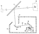
図1に示すように、本発明の第1実施形態によるHUD装置100は、移動体の一種である車両1に搭載され、インストルメントパネル2の収容部2aに収容されている。HUD装置100は、車両1の投影部材としてのウインドシールド3に画像を投影する。画像の表示光がウインドシールド3に反射されることで、HUD装置100は、車両1において座席4に着座した乗員により視認可能な虚像VIを表示する。すなわち、ウインドシールド3に反射される表示光が、車両1の室内において乗員の眼に到達し、乗員が表示光を虚像VIとして知覚する。そして、乗員は、虚像VIにより各種情報を認識することができる。虚像VIとして表示される各種情報としては、例えば、車速、燃料残量等の車両状態値、又は、道路情報、視界補助情報等のナビゲーション情報が挙げられる。
(First embodiment)
As shown in FIG. 1, the
車両1のウインドシールド3は、ガラスないしは合成樹脂等により透光性の板状に形成されている。ウインドシールド3において、室内側の面は、画像が投影される反射面3aを凹面状又は平坦な平面状に形成している。
The
このようなウインドシールド3の形状、ウインドシールド3に対するインストルメントパネル2の収容部2a及び座席4の相対位置は、一般的に、車両1の用途あるいはデザイン等に基づいて車両メーカにより設定されている。ここで、ウインドシールド3に反射された表示光が座席4に着座した乗員の眼の存在可能性が高い領域であるアイリプス(詳細は、JISD0021:1998参照)と重なって設定される視認領域EBに到達するように、HUD装置100は光学設計される。ここで視認領域EBとは、HUD装置により表示される虚像VIが視認可能となる空間領域である。
The shape of the
したがって、ウインドシールド3への表示光の入射角等の搭載条件は、搭載される車両1の車種によって異なり、制約を受ける。
Therefore, mounting conditions such as the incident angle of the display light on the
このようなHUD装置100の具体的構成を、図2〜12に基づいて、以下に説明する。図2に示すように、HUD装置100は、収容部材10、投射部20、平面鏡30、凹面鏡40、及び透光板50を備えている。
A specific configuration of such a
収容部材10は、例えば合成樹脂により遮光性を有する箱状に形成され、投射部20、平面鏡30、凹面鏡40、及び透光板50を収容する部材である。収容部材10は、ウインドシールド3と対向する箇所に、窓状の窓部12を有している。
The
投射部20は、図3にも詳細を示すように、光源22、集光レンズ24、投射レンズ26、及び液晶パネル28を有し、例えば箱状のケーシング20aにこれらを収容して形成されている。
As shown in detail in FIG. 3, the
光源22は、例えば複数の発光ダイオード素子であり、光源用回路基板22a上に配置されている。光源22は、光源用回路基板22a上の配線パターンを通じて、電源と電気的に接続されている。光源22は、通電により電流量に応じた発光量にて光源光を発する。これにより、光源22は、光源光を集光レンズ24へ向けて投射する。より詳細には、光源22は、例えば青色発光ダイオードを蛍光体で覆うことにより、疑似白色での発光が実現されている。
The
集光レンズ24は、光源22と投射レンズ26との間に配置され、合成樹脂ないしはガラス等からなる透光性の凸レンズ素子が発光ダイオードの数に合わせて配列されたレンズアレイである。集光レンズ24は、光源からの光源光を集光して投射レンズ26へ向けて射出する。
The condensing lens 24 is a lens array that is disposed between the
投射レンズ26は、集光レンズ24と液晶パネル28との間に配置され、合成樹脂ないしはガラス等からなる透光性のフレネルレンズとなっている。投射レンズ26は、集光レンズ24からの光源光を集光して液晶パネル28に向けて射出する。
The projection lens 26 is disposed between the condenser lens 24 and the
液晶パネル28は、例えば薄膜トランジスタ(Thin Film Transistor、TFT)を用いた液晶パネルであって、2次元方向に配列された複数の液晶画素から形成されるアクティブマトリクス型の液晶パネルである。液晶パネル28では、一対の偏光板及び当該一対の偏光板に挟まれた液晶層等が積層されている。偏光板は、所定方向に沿って偏光する光を透過させ、所定方向に垂直な方向に沿って偏光する光を遮光する性質を有し、一対の偏光板は当該所定方向を互いに実質直交して配置される。液晶層は、液晶画素毎の電圧印加により、印加電圧に応じて液晶層に入射する光の偏光方向を回転させることが可能となっている。
The
したがって、液晶パネル28が液晶画素毎の光源光の透過率を制御することで、投射部20は、画像の表示光を投射することが可能となっている。ここで、表示光は、射出側の偏光板の所定方向としての偏光軸の方向PADに直線偏光する光として、投射部20から投射される。なお、本実施形態では、液晶パネル28の画面は、長手方向LD及び短手方向SDを有する矩形状に形成され、偏光軸方向PADは、長手方向LDに対して135度をなす方向に設定されている。投射部20に投射された表示光は、平面鏡30に入射する。
Therefore, the
平面鏡30は、合成樹脂ないしはガラス等からなる基材の表面に、反射面32としてアルミニウムを蒸着させること等により形成されている。反射面32は、滑らかな平面状に形成されている。そして、平面鏡30は、投射部20からの表示光を凹面鏡40へ向けて反射する。
The
凹面鏡40は、合成樹脂ないしはガラス等からなる基材の表面に、反射面42としてアルミニウムを蒸着させること等により形成されている。反射面42は、凹面鏡40の中心が凹む凹面として、滑らかな曲面状に形成されている。そして、凹面鏡40は、平面鏡30からの表示光を反射する。凹面鏡40により反射された表示光は、透光板50を介して、ウインドシールド3へ向かう。
The
こうして投射部20からウインドシールド3に至る光路OPが構成されている。透光板50は、当該光路OP上に配置され、透光性を有する平板状に形成されている。特に本実施形態の透光板50は、凹面鏡40とウインドシールド3との間の光路上において、収容部材10の窓部12を塞ぐように配置されている。
Thus, an optical path OP from the
このような透光板50において、その表面の法線方向に沿った方向として、板厚方向VDが定義できる。そして板厚方向VDに対して垂直な第1延設方向MDが定義できる。さらに板厚方向VD及び第1延設方向MDに対して垂直な第2延設方向TDが定義できる。
In such a
透光板50は、例えばポリカーボネイト樹脂ないしはアクリル樹脂等の合成樹脂により形成されている。本実施形態の透光板50は、板厚方向VDに沿った寸法である板厚を例えば0.5mmとし、全体を実質同じ板厚としている。そして透光板50は、板厚方向VDの屈折率NVD、第1延設方向MDの屈折率NMD、及び第2延設方向TDの屈折率NTDとを、互いに異ならせている。具体的に本実施形態では、板厚方向VDの屈折率NVD=1.5845であり、第1延設方向MDの屈折率NMD=1.5853、第2延設方向TDの屈折率NTD=1.5851である。これらの屈折率NVD,NMD,NTDは、580nmの波長の光に対する屈折率である。
The
これと共に、透光板50は、光軸OAに対して板厚方向VDを傾斜させて配置されている。特に本実施形態では、透光板50は、光軸OAに対して板厚方向VDを傾斜させた状態で固定配置されている。ここで本実施形態における光軸OAとは、液晶パネル28において2次元方向に配列された液晶画素のうち、画面の中心となる画素から、視認領域EBの中心まで光線追跡して得られる光線の経路である。特に本実施形態について言えば、光軸OAは、画面の中心となる画素から、画面と垂直に射出した主光線の経路である。
At the same time, the
また、図4に示すように、光軸OAに垂直な仮想平面IP上において、画面の長手方向LDに対応する長手対応方向RLDと、画面の短手方向SDに対応する短手対応方向RSDと、を定義する。長手対応方向RLDは、画面上の長手方向LDをベクトルとして光軸OAに沿って仮想平面IP上に射影することで得られる方向である。短手対応方向RSDは、画面上の短手方向SDをベクトルとして光軸OAに沿って仮想平面IP上に射影することで得られる方向である。すなわち、平面鏡30及び凹面鏡40での反射等により光軸OAの向きが変わると、長手対応方向RLD及び短手対応方向RSDもこれに合わせて向きが変わることとなる。
Further, as shown in FIG. 4, on the virtual plane IP perpendicular to the optical axis OA, a longitudinal corresponding direction RLD corresponding to the longitudinal direction LD of the screen and a short corresponding direction RSD corresponding to the lateral direction SD of the screen Define. The longitudinal corresponding direction RLD is a direction obtained by projecting on the virtual plane IP along the optical axis OA using the longitudinal direction LD on the screen as a vector. The short correspondence direction RSD is a direction obtained by projecting the short direction SD on the screen onto the virtual plane IP along the optical axis OA as a vector. In other words, when the direction of the optical axis OA changes due to reflection by the
図2に示すように表示光は、板厚方向VDが傾斜して設けられる透光板50を、例えば光軸OAに沿って、透過することとなる。この際、各方向VD,MD,TDの屈折率NVD,NMD,NTDが異なっていることで、表示光に位相差が生じ、偏光の方位角が回転したり、偏光の楕円率が変わることとなる。こうした表示光の偏光の状態を、ウインドシールド3への入射角に合わせたものとすることで、乗員が視認する虚像VIの輝度が調整される。
As shown in FIG. 2, the display light is transmitted through the
以下、透光板50の傾斜とその輝度調整機能の関連性について、シミュレーション結果を示す図5,7,11を用いつつ、詳細に説明する。
Hereinafter, the relationship between the inclination of the
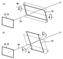
図5には、第1延設方向MDを回転軸として透光板50を回転させた場合(図6(a)参照)の傾斜角と、表示光に及ぼす位相差との関係がプロットされている。これによれば、透光板50の傾斜角が0度(すなわち、板厚方向VDが光軸OAに沿った状態)では、位相差が距離換算で150nm未満である。傾斜角を増加させると、20度あたりから位相差が徐々に増え始め、傾斜角45度では、距離換算で200nmより大きい位相差を得ることができる。
FIG. 5 plots the relationship between the tilt angle when the
なお、図5の位相差は、580nmの波長の光に対する位相差であるから、傾斜角が0度の状態では、透光板50は略4分の1波長板として機能し、傾斜角を増加させるに従って、2分の1波長板の機能に近づけることができる。
The phase difference in FIG. 5 is a phase difference with respect to light having a wavelength of 580 nm. Therefore, when the tilt angle is 0 degree, the
次に、図7には、上述の説明の傾斜角45度の状態で、板厚方向VDを回転軸として透光板を回転させた場合(図6(b)参照)の回転角と、視認される虚像VIの相対輝度との関係がプロットされている。これによれば、透光板50の回転角を約150度としたとき、相対輝度が15685となり、最大値となる。また、透光板50の回転角を約30度としたとき、相対輝度が2629となり、最小値となる。なお、透光板50の回転角は、長手対応方向RLDを基準角としている。すなわち、第1延設方向MDが長手対応方向RLDと一致する場合、0度となる。
Next, FIG. 7 shows the rotation angle when the translucent plate is rotated with the plate thickness direction VD as the rotation axis in the state of the inclination angle of 45 degrees as described above (see FIG. 6B), and the visual recognition. The relationship with the relative luminance of the virtual image VI is plotted. According to this, when the rotation angle of the
比較例として、図8には、傾斜角0度の状態で、板厚方向VDを回転軸として透光板を回転させた場合の回転角と、視認される虚像VIの相対輝度との関係がプロットされている。これによれば、透光板の回転角を67.5度又は157.5度としたとき、相対輝度が14950となり、最大値となる。また、透光板50の回転角を約20度又は約110度としたとき、相対輝度が5051となり、最小値となる。
As a comparative example, FIG. 8 shows the relationship between the rotation angle when the translucent plate is rotated about the plate thickness direction VD and the relative luminance of the visible virtual image VI in a state where the inclination angle is 0 degree. It is plotted. According to this, when the rotation angle of the translucent plate is 67.5 degrees or 157.5 degrees, the relative luminance is 14950, which is the maximum value. Further, when the rotation angle of the
より詳細に説明すると、図9に示すように、ウインドシールド3の反射断面WRPが長手対応方向RLDに対して90度をなす方向に沿って配置されている。したがって、透光板50透過後の表示光が、反射断面WRPに対して垂直な方向NDの(すなわち0度)の成分が多い偏光であれば、ウインドシールド3における表示光の反射率が高くなり、虚像VIの輝度を高めることができる。このため比較例では、投射部の偏光軸方向PADの角度と反射断面WRPに対して垂直な方向NDの角度との中間である67.5度又は157.5度に第1延設方向MDを設定すると、輝度を高めることができると考えられる。しかしながら、比較例では、表示光に十分な位相差を与えられなかったため、相対輝度の最大値は、本実施形態と比較して小さい。
More specifically, as shown in FIG. 9, the reflection cross section WRP of the
こうしたシミュレーション結果の比較から、光軸OAに対して透光板50の板厚方向VDを傾斜させて配置した方が、調整範囲が広く、透光板50による輝度の調整作用が大きいことがわかる。
From the comparison of the simulation results, it can be seen that when the thickness direction VD of the
以上では、透光板50に基づいて定義され得る第1延設方向MDを回転軸として、当該透光板50の板厚方向VDが光軸OAに対して傾斜した状態で配置された。この他に図10のように、投射部20の画像に基づいて定義される回転軸により、板厚方向VDが光軸OAに対して傾斜した状態で配置されていてもよい。
In the above description, the first extending direction MD that can be defined based on the
まず、板厚方向VDが光軸OAに沿った状態、かつ、第1延設方向MDが長手対応方向RLDに沿った状態から、長手対応方向RLDを回転軸としてα度回転させる(図10(a)参照)。次に、透光板50を短手対応方向RSDを回転軸としてβ度回転させる(図10(b)参照)。こうして、透光板50の板厚方向VDが光軸OAに対して傾斜した状態となる。
First, from the state where the plate thickness direction VD is along the optical axis OA and the first extending direction MD is along the longitudinal corresponding direction RLD, the longitudinal corresponding direction RLD is rotated by α degrees (FIG. 10 ( a)). Next, the
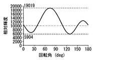
αを21度とし、かつ、βを−41度とした場合の係る状態で、板厚方向VDを回転軸として透光板50を回転させた場合(図10(c)参照)の回転角と、視認される虚像VIの相対輝度との関係が図11にプロットされている。これによれば、透光板50の回転角を約150度としたとき、相対輝度が19019となり、最大値となる。
In a state where α is 21 degrees and β is −41 degrees, the rotation angle when the
なお、図7,11において相対輝度が最大値をとるように透光板50を配置することが最適とは限らないことに留意すべきである。なぜならば、図5,7,11における相対輝度とは、虚像VIを裸眼の乗員が視認した場合の輝度であるので、偏光サングラスを装用した乗員による虚像VIの視認性を考慮する余地がある。すなわち、裸眼の乗員と偏光サングラスを装用した乗員との視認性のバランスが取れるように、最大値からずれた状態で透光板50を配置してもよいのである。
7 and 11, it should be noted that the
本実施形態における透光板50の配置について、より詳細に説明する。ここで図12に示すように、中心に光軸OAが通る仮想の楕円体であって、板厚方向VD、第1延設方向MD、及び第2延設方向TDに主軸をとり、各主軸の長さを対応する各方向VD,MD,TDの屈折率NVD,NMD,NTDの半値とする屈折率楕円体RIEを定義する。そして、当該屈折率楕円体RIEの中心を通ると共に、光軸OAに垂直な断面である仮想の楕円切断面SEを定義する。
The arrangement of the
本実施形態では、この楕円切断面SEにおける長軸MAAと短軸MIAとの長さの差の絶対値が第1延設方向MDの屈折率NMDと第2延設方向TDの屈折率NTDとの差の絶対値よりも大きくなるように、透光板50が配置される。この配置の条件は、上述の角度α,βを用いて書き換えできる。まず、角度α,βの回転による回転行列は、

この行列回転の各成分を用いると、配置の条件は、
(作用効果)
以上説明した第1実施形態の作用効果を以下に説明する。
(Function and effect)
The operational effects of the first embodiment described above will be described below.
第1実施形態によると、投射部20からウインドシールド3に至る光路OP上には、透光性を有する板状の透光板50が配置されている。透光板50は、板厚方向VDの屈折率NVDと、第1延設方向MDの屈折率NMDと、第2延設方向TDの屈折率NTDとを、互いに異ならせているから、投射部20に投射された表示光は、ウインドシールド3に至るまでに、位相差を生じ得る。さらに、透光板50は、光軸OAに対して板厚方向VDを傾斜させて配置されているから、板厚方向VDの屈折率NVDの違いを利用して、傾斜に応じた位相差を実現し得る。このような透光板50の傾斜配置により、例えば設計段階で、表示光における偏光の方位角及び偏光の楕円率の両方を調整可能となったことで、HUD装置100は、車両1に搭載される制約下においても、ウインドシールド3での反射の具合を改善させて、視認し易い虚像VIを提供することができるのである。
According to the first embodiment, a plate-like
また、第1実施形態によると、仮想の楕円切断面SEにおける長軸MAAと短軸MIAとの長さの差の絶対値は、第1延設方向MDの屈折率NMDと第2延設方向TDの屈折率NTDとの差の絶対値よりも大きくなっている。このような透光板50の配置によれば、板厚方向VDを光軸OAに沿わせて配置した場合よりも、表示光に作用する位相差を大きくできる。したがって、車両1に搭載される制約下においても、確実にウインドシールド3での反射の具合を向上させて、視認し易い虚像VIを提供することができるのである。
Further, according to the first embodiment, the absolute value of the difference in length between the major axis MAA and the minor axis MIA in the virtual elliptical cutting plane SE is the refractive index NMD in the first extending direction MD and the second extending length. It is larger than the absolute value of the difference between the refractive index N TD direction TD. According to such an arrangement of the
また、第1実施形態の平板状の透光板50によれば、同様の調整作用を表示光全体に及ぼすことが容易となるので、虚像VIの輝度ムラを抑制することができる。
Moreover, according to the flat light-transmitting
また、第1実施形態によると、投射部20を収容する収容部材10をさらに備え、透光板50は、収容部材10の窓部12を塞ぐように配置される。装置100の外部から内部に異物が侵入することを、透光板50により防止することができるので、部品点数の増加を抑制しつつ、視認し易い虚像VIを長きに亘って維持することができる。
In addition, according to the first embodiment, the
(第2実施形態)
図13に示すように、本発明の第2実施形態は第1実施形態の変形例である。第2実施形態について、第1実施形態とは異なる点を中心に説明する。
(Second Embodiment)
As shown in FIG. 13, the second embodiment of the present invention is a modification of the first embodiment. The second embodiment will be described with a focus on differences from the first embodiment.
第2実施形態の透光板250は、第1実施形態と同様に、凹面鏡40とウインドシールド3との間の光路上において、収容部材10の窓部12を塞ぐように設けられている。
The
第2実施形態の透光板250は、湾曲板状に形成されている。具体的に透光板250は、HUD装置200の内部側に入り込むように凹状に湾曲している。当該湾曲は、例えば円筒状の湾曲であり、この湾曲における曲率半径は、例えば150cmに設定されている。透光板250は、全体を実質同じ板厚としている。
The
第2実施形態においても、光軸OAと透光板250とが交わる箇所において、光軸OAに対して板厚方向VDを傾斜させた状態で固定配置されている。このような湾曲板状の透光板250の場合、光軸OA外において、板厚方向VDが光軸OAの方向と一致する箇所が存在する可能性がある。しかしながら、光軸OAと透光板250とが交わる箇所において、板厚方向VDが傾斜していれば、透光板250は表示光に相応の作用を及ぼし得る。
Also in the second embodiment, the optical axis OA and the
こうした第2実施形態によると、湾曲面状の透光板250が光軸OAに対して傾斜して配置されることにより、装置100の外部から内部に入射し得る例えば太陽光等の外光を、乗員側に到達させないように透光板250で反射可能となるので、外光による虚像VIのコントラストの悪化を抑制しつつ、傾斜に応じた位相差を実現できる。したがって、視認し易い虚像VIを提供することができる。
According to such a second embodiment, the curved surface-shaped
(第3実施形態)
図14に示すように、本発明の第3実施形態は第2実施形態の変形例である。第3実施形態について、第2実施形態とは異なる点を中心に説明する。
(Third embodiment)
As shown in FIG. 14, the third embodiment of the present invention is a modification of the second embodiment. The third embodiment will be described with a focus on differences from the second embodiment.
第3実施形態の透光板350は、第1,2実施形態と同様に、凹面鏡40とウインドシールド3との間の光路上において、収容部材10の窓部12を塞ぐように配置されている。ここでHUD装置300は、透光板350と貼り合わされる偏光板352を、視認規制部として、さらに備えている。
Similar to the first and second embodiments, the
偏光板352は、透光板350と貼り合わされた状態で、窓部12を透光板350と共に塞いでいる。特に本実施形態の偏光板352は、ポリビニルアルコールに二色性色素であるヨウ素を添加して形成された吸収型偏光板である。この偏光板352は、ヨウ素分子の配向方向によって透過軸と吸収軸とを互いに直交した状態で有している。そして偏光板352は、透過軸に沿って偏光する光を透過させ、吸収軸に沿って偏光する光を吸収する性質を有している。
The
ここで偏光板352は、例えば透光板350よりも凹面鏡側に、投射部20から投射された直線偏光の表示光における偏光方向(すなわち、偏光軸方向PAD)にその透過軸を合わせて配置されている。このような配置により、偏光板352は、表示光の多くをそのまま透光板350へ透過させる一方、収容部材10の内部が外部から視認されることを規制する。また、偏光板352は、車両1の外部から例えばウインドシールド3を介してHUD装置300に入射する太陽光等の外光の一部を遮光する。
Here, the
第3実施形態によると、視認規制部が透光板350と貼り合わされた状態で、窓部12を透光板350と共に塞ぎ、収容部材10内部が外部から視認されることを規制している。これによれば、視認規制部及び透光板350を表示光がまとめて透過することにより、輝度の損失を抑制しつつ、内部を覗かれ難くすることができる。
According to the third embodiment, the
また、第3実施形態によると、視認規制部は、偏光板352である。これによれば、直線偏光の投射光を偏光板352で透過させることで、確実に輝度の損失を抑制しつつ、装置300の内部を覗かれ難くすることができる。
Further, according to the third embodiment, the visual restriction part is the
(第4実施形態)
図15に示すように、本発明の第4実施形態は第2実施形態の変形例である。第4実施形態について、第2実施形態とは異なる点を中心に説明する。
(Fourth embodiment)
As shown in FIG. 15, the fourth embodiment of the present invention is a modification of the second embodiment. The fourth embodiment will be described with a focus on differences from the second embodiment.
第4実施形態のHUD装置400において透光板450は、第1〜3実施形態と同様に、凹面鏡40とウインドシールド3との間の光路上において、収容部材10の窓部12を塞ぐように配置されている。
In the
第1,2実施形態の着色されていない透光板50,250に対して、第4実施形態の透光板450は、透光性を有しつつも、着色されている。本実施形態では、透光板450は、例えばスモーク調に着色される。着色における色相は、例えばインストルメントパネル2の色相と同系統であることが好ましい。
In contrast to the uncolored
また、当該透光板450の着色方法としては、染料による透光板450基材への着色、又は透光板450表面への印刷等の方法が採用され得る。
Further, as a coloring method of the
第4実施形態によると、着色された透光板450により、部品点数の増加を抑制しつつ、装置400の内部を覗かれ難くすることができる。
According to the fourth embodiment, the colored
(他の実施形態)
以上、本発明の複数の実施形態について説明したが、本発明は、それらの実施形態に限定して解釈されるものではなく、本発明の要旨を逸脱しない範囲内において種々の実施形態及び組み合わせに適用することができる。
(Other embodiments)
Although a plurality of embodiments of the present invention have been described above, the present invention is not construed as being limited to these embodiments, and various embodiments and combinations can be made without departing from the scope of the present invention. Can be applied.
具体的に、変形例1としては、透光板50は、収容部材10の窓部12を塞いでいなくてもよい。この例として図16では、透光板50は、投射部20と平面鏡30の間の光路上に、光軸OAに対して板厚方向VDを傾斜させて配置されている。
Specifically, as a first modification, the
変形例2としては、透光板50は、光軸OAに対して板厚方向VDを傾斜させた状態で、固定配置されたものに限らない。この例として、HUD装置100は、光軸OAに対する透光板50の板厚方向VDを変える可動機構を、さらに備えていてもよい。例えば製造工程において生じ得る投射部20の表示光の輝度の誤差、位置関係の誤差等に伴う虚像VIの視認性のばらつきを、可動機構によって調整することができる。
As a second modification, the
第3実施形態に関する変形例3としては、視認規制部として用いる偏光板352は、透光板350よりもウインドシールド3側に、配置されていてもよい。
As a third modified example related to the third embodiment, the
第3実施形態に関する変形例4としては、視認規制部として用いる偏光板352は、反射型偏光板であってもよい。また、視認規制部として、偏光板352以外に、フィルム状のハーフミラーが採用されていてもよい。
As a fourth modified example related to the third embodiment, the
変形例5としては、投射部20には、液晶パネル28を用いた方式以外の方式が採用されていてもよい。この例として、投射部20は、レーザ光束を走査して、スクリーン上に画像を描画することにより、当該画像の画素を構成するレーザ光束を表示光として投射する方式であってもよい。この場合、光軸OAは、画像の中心の画素を構成するレーザ光束の経路である。
As a fifth modification, the
変形例6としては、車両1以外の船舶ないしは飛行機等の各種移動体(輸送機器)に、本発明を適用してもよい。
As a sixth modification, the present invention may be applied to various moving bodies (transport equipment) such as ships or airplanes other than the
100,200,300,400 HUD装置、1 車両(移動体)、3 ウインドシールド(投影部材)、10 収容部材、12 窓部、20 投射部、50,250,350,450 透光板、352 偏光板(視認規制部)、VI 虚像、OP 光路、OA 光軸 100, 200, 300, 400 HUD device, 1 vehicle (moving body), 3 windshield (projection member), 10 housing member, 12 window portion, 20 projection portion, 50, 250, 350, 450 translucent plate, 352 polarized light Board (visual restriction part), VI virtual image, OP optical path, OA optical axis
Claims (7)
前記表示光を投射する投射部(20)と、
前記投射部から前記投影部材に至る光路(OP)上に配置され、透光性を有する板状の透光板(50,250,350,450)と、を備え、
前記透光板は、板厚方向(VD)の屈折率と、前記板厚方向に対して垂直な第1延設方向(MD)の屈折率と、前記板厚方向及び前記第1延設方向に対して垂直な第2延設方向(TD)の屈折率とを互いに異ならせていると共に、光軸(OA)に対して前記板厚方向を傾斜させて配置され、
中心に前記光軸が通る仮想の楕円体であって、前記板厚方向、前記第1延設方向、及び前記第2延設方向に主軸をとり、各前記主軸の長さを対応する各前記方向の屈折率の半値とする屈折率楕円体(RIE)を定義すると、
前記屈折率楕円体の中心を通ると共に、前記光軸に垂直な断面である仮想の楕円切断面(SE)における長軸(MAA)と短軸(MIA)との長さの差の絶対値は、前記第1延設方向の屈折率と前記第2延設方向の屈折率との差の絶対値よりも大きいヘッドアップディスプレイ装置。 A head-up display device that is mounted on a moving body (1) and displays a virtual image (VI) that can be seen by an occupant by reflecting display light on a projection member (3) of the moving body,
A projection unit (20) for projecting the display light;
A plate-shaped translucent plate (50, 250, 350, 450) disposed on an optical path (OP) from the projection unit to the projection member and having translucency,
The translucent plate includes a refractive index in a plate thickness direction (VD), a refractive index in a first extending direction (MD) perpendicular to the plate thickness direction, the plate thickness direction, and the first extending direction. The second extending direction (TD) perpendicular to the refractive index is different from each other, and the plate thickness direction is inclined with respect to the optical axis (OA) ,
A virtual ellipsoid through which the optical axis passes in the center, each having a main axis in the plate thickness direction, the first extending direction, and the second extending direction, and corresponding lengths of the main axes; Defining a refractive index ellipsoid (RIE) with half the refractive index in the direction,
The absolute value of the difference in length between the major axis (MAA) and the minor axis (MIA) in the virtual ellipsoidal section (SE) that passes through the center of the refractive index ellipsoid and is perpendicular to the optical axis is The head-up display device having an absolute value larger than the absolute value of the difference between the refractive index in the first extending direction and the refractive index in the second extending direction .
前記収容部材は、前記投影部材と対向する箇所に、窓状の窓部(12)を有し、
前記透光板は、前記窓部を塞ぐように配置される請求項1から3のいずれか1項に記載のヘッドアップディスプレイ装置。 A storage member (10) for storing the projection unit;
The housing member has a window-shaped window portion (12) at a location facing the projection member,
The transparent plate is a head-up display device according to any one of claims 1 to 3 disposed so as to close the window.
前記視認規制部は、偏光板である請求項5に記載のヘッドアップディスプレイ装置。 The projection unit projects the display light as linearly polarized light,
The head-up display device according to claim 5 , wherein the visual restriction part is a polarizing plate.
Priority Applications (2)
| Application Number | Priority Date | Filing Date | Title |
|---|---|---|---|
| JP2016027338A JP6432540B2 (en) | 2016-02-16 | 2016-02-16 | Head-up display device |
| PCT/JP2016/081202 WO2017141491A1 (en) | 2016-02-16 | 2016-10-21 | Head-up display device |
Applications Claiming Priority (1)
| Application Number | Priority Date | Filing Date | Title |
|---|---|---|---|
| JP2016027338A JP6432540B2 (en) | 2016-02-16 | 2016-02-16 | Head-up display device |
Publications (3)
| Publication Number | Publication Date |
|---|---|
| JP2017146424A JP2017146424A (en) | 2017-08-24 |
| JP2017146424A5 JP2017146424A5 (en) | 2018-01-25 |
| JP6432540B2 true JP6432540B2 (en) | 2018-12-05 |
Family
ID=59625795
Family Applications (1)
| Application Number | Title | Priority Date | Filing Date |
|---|---|---|---|
| JP2016027338A Active JP6432540B2 (en) | 2016-02-16 | 2016-02-16 | Head-up display device |
Country Status (2)
| Country | Link |
|---|---|
| JP (1) | JP6432540B2 (en) |
| WO (1) | WO2017141491A1 (en) |
Families Citing this family (11)
| Publication number | Priority date | Publication date | Assignee | Title |
|---|---|---|---|---|
| JP6644265B2 (en) * | 2017-06-30 | 2020-02-12 | 株式会社Jvcケンウッド | Virtual image display |
| JP6711337B2 (en) * | 2017-09-07 | 2020-06-17 | 株式会社デンソー | Head-up display device and image projection unit |
| WO2019102775A1 (en) * | 2017-11-22 | 2019-05-31 | 日本精機株式会社 | Head-up display device |
| JP6593464B2 (en) | 2018-01-12 | 2019-10-23 | 株式会社Jvcケンウッド | Virtual image display device |
| JP6593465B2 (en) * | 2018-01-12 | 2019-10-23 | 株式会社Jvcケンウッド | Virtual image display device |
| KR102077635B1 (en) * | 2018-01-12 | 2020-02-14 | 가부시키가이샤 제이브이씨 켄우드 | Virtual display |
| JP6593462B2 (en) | 2018-01-12 | 2019-10-23 | 株式会社Jvcケンウッド | Virtual image display device |
| JP6593461B2 (en) * | 2018-01-12 | 2019-10-23 | 株式会社Jvcケンウッド | Virtual image display device |
| JP6793344B2 (en) * | 2018-02-28 | 2020-12-02 | パナソニックIpマネジメント株式会社 | Display system, mobile |
| JP2019164239A (en) * | 2018-03-19 | 2019-09-26 | 株式会社リコー | Display unit and apparatus |
| EP4208751A1 (en) * | 2020-09-01 | 2023-07-12 | 3M Innovative Properties Company | Heads up display systems |
Family Cites Families (7)
| Publication number | Priority date | Publication date | Assignee | Title |
|---|---|---|---|---|
| JP2000028957A (en) * | 1998-07-07 | 2000-01-28 | Asahi Glass Co Ltd | Information display device |
| JP4414612B2 (en) * | 2001-05-31 | 2010-02-10 | 矢崎総業株式会社 | Vehicle display device |
| JP5640457B2 (en) * | 2009-05-25 | 2014-12-17 | 日本精機株式会社 | Vehicle display device |
| JP6363828B2 (en) * | 2013-08-30 | 2018-07-25 | 旭化成株式会社 | Optical system |
| JP6221941B2 (en) * | 2014-05-26 | 2017-11-01 | 株式会社デンソー | Head-up display device |
| JP6446259B2 (en) * | 2014-12-24 | 2018-12-26 | 旭化成株式会社 | Head-up display device |
| JP6489841B2 (en) * | 2015-01-21 | 2019-03-27 | パイオニア株式会社 | Head-up display |
-
2016
- 2016-02-16 JP JP2016027338A patent/JP6432540B2/en active Active
- 2016-10-21 WO PCT/JP2016/081202 patent/WO2017141491A1/en active Application Filing
Also Published As
| Publication number | Publication date |
|---|---|
| JP2017146424A (en) | 2017-08-24 |
| WO2017141491A1 (en) | 2017-08-24 |
Similar Documents
| Publication | Publication Date | Title |
|---|---|---|
| JP6432540B2 (en) | Head-up display device | |
| KR102208724B1 (en) | Head-up display device | |
| JP6451523B2 (en) | Head-up display device | |
| JP6297238B1 (en) | Vehicle display device | |
| JP6287354B2 (en) | Scanning display device | |
| JP6563711B2 (en) | Head-up display device | |
| WO2014132817A1 (en) | Headup display device | |
| CN110770635A (en) | Head-up display device | |
| WO2017187758A1 (en) | Head-up display device | |
| JP6809441B2 (en) | Virtual image display device | |
| JP6922655B2 (en) | Virtual image display device | |
| US20220252900A1 (en) | Image display device | |
| WO2017131185A1 (en) | Head-up display device for vehicle | |
| CN218213623U (en) | Display device, head-up display and traffic equipment | |
| CN116413907A (en) | Display device, head-up display and traffic equipment | |
| US10620433B2 (en) | Head-up display device | |
| US10768417B2 (en) | Display device and vehicle head-up display apparatus | |
| JP6620706B2 (en) | Head-up display device | |
| WO2023090092A1 (en) | Image projection device | |
| WO2021240985A1 (en) | Virtual-image display device | |
| WO2017145558A1 (en) | Head-up display device | |
| WO2023176507A1 (en) | Image projection device | |
| KR20190080311A (en) | Head-up Display apparatus |
Legal Events
| Date | Code | Title | Description |
|---|---|---|---|
| A521 | Request for written amendment filed |
Free format text: JAPANESE INTERMEDIATE CODE: A523 Effective date: 20171205 |
|
| A621 | Written request for application examination |
Free format text: JAPANESE INTERMEDIATE CODE: A621 Effective date: 20171205 |
|
| TRDD | Decision of grant or rejection written | ||
| A01 | Written decision to grant a patent or to grant a registration (utility model) |
Free format text: JAPANESE INTERMEDIATE CODE: A01 Effective date: 20181009 |
|
| A61 | First payment of annual fees (during grant procedure) |
Free format text: JAPANESE INTERMEDIATE CODE: A61 Effective date: 20181022 |
|
| R151 | Written notification of patent or utility model registration |
Ref document number: 6432540 Country of ref document: JP Free format text: JAPANESE INTERMEDIATE CODE: R151 |
|
| R250 | Receipt of annual fees |
Free format text: JAPANESE INTERMEDIATE CODE: R250 |
|
| R250 | Receipt of annual fees |
Free format text: JAPANESE INTERMEDIATE CODE: R250 |
|
| R250 | Receipt of annual fees |
Free format text: JAPANESE INTERMEDIATE CODE: R250 |