JP2015513858A - Multi-function automatic video recorder - Google Patents
Multi-function automatic video recorder Download PDFInfo
- Publication number
- JP2015513858A JP2015513858A JP2014560133A JP2014560133A JP2015513858A JP 2015513858 A JP2015513858 A JP 2015513858A JP 2014560133 A JP2014560133 A JP 2014560133A JP 2014560133 A JP2014560133 A JP 2014560133A JP 2015513858 A JP2015513858 A JP 2015513858A
- Authority
- JP
- Japan
- Prior art keywords
- camera
- subject
- base station
- remote device
- positioner
- Prior art date
- Legal status (The legal status is an assumption and is not a legal conclusion. Google has not performed a legal analysis and makes no representation as to the accuracy of the status listed.)
- Pending
Links
Images


Classifications
-
- H—ELECTRICITY
- H04—ELECTRIC COMMUNICATION TECHNIQUE
- H04N—PICTORIAL COMMUNICATION, e.g. TELEVISION
- H04N23/00—Cameras or camera modules comprising electronic image sensors; Control thereof
- H04N23/60—Control of cameras or camera modules
- H04N23/66—Remote control of cameras or camera parts, e.g. by remote control devices
-
- F—MECHANICAL ENGINEERING; LIGHTING; HEATING; WEAPONS; BLASTING
- F16—ENGINEERING ELEMENTS AND UNITS; GENERAL MEASURES FOR PRODUCING AND MAINTAINING EFFECTIVE FUNCTIONING OF MACHINES OR INSTALLATIONS; THERMAL INSULATION IN GENERAL
- F16M—FRAMES, CASINGS OR BEDS OF ENGINES, MACHINES OR APPARATUS, NOT SPECIFIC TO ENGINES, MACHINES OR APPARATUS PROVIDED FOR ELSEWHERE; STANDS; SUPPORTS
- F16M11/00—Stands or trestles as supports for apparatus or articles placed thereon Stands for scientific apparatus such as gravitational force meters
- F16M11/02—Heads
- F16M11/04—Means for attachment of apparatus; Means allowing adjustment of the apparatus relatively to the stand
- F16M11/06—Means for attachment of apparatus; Means allowing adjustment of the apparatus relatively to the stand allowing pivoting
- F16M11/10—Means for attachment of apparatus; Means allowing adjustment of the apparatus relatively to the stand allowing pivoting around a horizontal axis
-
- F—MECHANICAL ENGINEERING; LIGHTING; HEATING; WEAPONS; BLASTING
- F16—ENGINEERING ELEMENTS AND UNITS; GENERAL MEASURES FOR PRODUCING AND MAINTAINING EFFECTIVE FUNCTIONING OF MACHINES OR INSTALLATIONS; THERMAL INSULATION IN GENERAL
- F16M—FRAMES, CASINGS OR BEDS OF ENGINES, MACHINES OR APPARATUS, NOT SPECIFIC TO ENGINES, MACHINES OR APPARATUS PROVIDED FOR ELSEWHERE; STANDS; SUPPORTS
- F16M11/00—Stands or trestles as supports for apparatus or articles placed thereon Stands for scientific apparatus such as gravitational force meters
- F16M11/02—Heads
- F16M11/18—Heads with mechanism for moving the apparatus relatively to the stand
-
- F—MECHANICAL ENGINEERING; LIGHTING; HEATING; WEAPONS; BLASTING
- F16—ENGINEERING ELEMENTS AND UNITS; GENERAL MEASURES FOR PRODUCING AND MAINTAINING EFFECTIVE FUNCTIONING OF MACHINES OR INSTALLATIONS; THERMAL INSULATION IN GENERAL
- F16M—FRAMES, CASINGS OR BEDS OF ENGINES, MACHINES OR APPARATUS, NOT SPECIFIC TO ENGINES, MACHINES OR APPARATUS PROVIDED FOR ELSEWHERE; STANDS; SUPPORTS
- F16M11/00—Stands or trestles as supports for apparatus or articles placed thereon Stands for scientific apparatus such as gravitational force meters
- F16M11/20—Undercarriages with or without wheels
- F16M11/2007—Undercarriages with or without wheels comprising means allowing pivoting adjustment
- F16M11/2014—Undercarriages with or without wheels comprising means allowing pivoting adjustment around a vertical axis
-
- F—MECHANICAL ENGINEERING; LIGHTING; HEATING; WEAPONS; BLASTING
- F16—ENGINEERING ELEMENTS AND UNITS; GENERAL MEASURES FOR PRODUCING AND MAINTAINING EFFECTIVE FUNCTIONING OF MACHINES OR INSTALLATIONS; THERMAL INSULATION IN GENERAL
- F16M—FRAMES, CASINGS OR BEDS OF ENGINES, MACHINES OR APPARATUS, NOT SPECIFIC TO ENGINES, MACHINES OR APPARATUS PROVIDED FOR ELSEWHERE; STANDS; SUPPORTS
- F16M11/00—Stands or trestles as supports for apparatus or articles placed thereon Stands for scientific apparatus such as gravitational force meters
- F16M11/20—Undercarriages with or without wheels
- F16M11/24—Undercarriages with or without wheels changeable in height or length of legs, also for transport only, e.g. by means of tubes screwed into each other
- F16M11/242—Undercarriages with or without wheels changeable in height or length of legs, also for transport only, e.g. by means of tubes screwed into each other by spreading of the legs
-
- H—ELECTRICITY
- H04—ELECTRIC COMMUNICATION TECHNIQUE
- H04N—PICTORIAL COMMUNICATION, e.g. TELEVISION
- H04N23/00—Cameras or camera modules comprising electronic image sensors; Control thereof
- H04N23/50—Constructional details
-
- H—ELECTRICITY
- H04—ELECTRIC COMMUNICATION TECHNIQUE
- H04N—PICTORIAL COMMUNICATION, e.g. TELEVISION
- H04N23/00—Cameras or camera modules comprising electronic image sensors; Control thereof
- H04N23/60—Control of cameras or camera modules
- H04N23/61—Control of cameras or camera modules based on recognised objects
- H04N23/611—Control of cameras or camera modules based on recognised objects where the recognised objects include parts of the human body
-
- F—MECHANICAL ENGINEERING; LIGHTING; HEATING; WEAPONS; BLASTING
- F16—ENGINEERING ELEMENTS AND UNITS; GENERAL MEASURES FOR PRODUCING AND MAINTAINING EFFECTIVE FUNCTIONING OF MACHINES OR INSTALLATIONS; THERMAL INSULATION IN GENERAL
- F16M—FRAMES, CASINGS OR BEDS OF ENGINES, MACHINES OR APPARATUS, NOT SPECIFIC TO ENGINES, MACHINES OR APPARATUS PROVIDED FOR ELSEWHERE; STANDS; SUPPORTS
- F16M2200/00—Details of stands or supports
- F16M2200/02—Locking means
- F16M2200/021—Locking means for rotational movement
- F16M2200/022—Locking means for rotational movement by friction
Abstract
開示されている自動ビデオ記録システムは、リモート装置し、リモート装置は、記録対象である被写体と関連付けられ、防水性及び耐衝撃性を有し、被写体に対する記録カメラの方向付けを支援し、音声指示を検知し、且つ、被写体の音響及び音声を記録する。装置は、そのコンポーネントの統合の様々な程度を使用することにより、構築されてもよい。本明細書の関係する方法は、被写体の場所及び速度に応じて、カメラの焦点及びズームを自動的に調節するステップを含む。【選択図】図2The disclosed automatic video recording system is a remote device, the remote device is associated with the subject to be recorded, has waterproof and impact resistance, supports the orientation of the recording camera with respect to the subject, and provides voice instructions And the sound and sound of the subject are recorded. A device may be constructed by using various degrees of integration of its components. The related method herein includes automatically adjusting the focus and zoom of the camera depending on the location and speed of the subject. [Selection] Figure 2
Description
活動に参加する人物を記録することは、重要な仕事である。サーファは、後で楽しむために、或いは、自身のサーフィンテクニックを改善するために、自身のサーフィン実技をキャプチャすることを所望するであろう。父親は、フットボールの試合における息子の決勝タッチダウンを記録することを所望するであろう。母親は、娘の記録破りの体操演技をキャプチャすることを所望するであろう。これらの例においては、カメラは、通常、且つ、しばしば、最良の結果を得るために、参加者から、或いは、更に一般的には、被写体から、相対的に遠く離れている。被写体を記録するには、カメラを制御及び位置決めするべく、第2の人物が必要とされる。人間は不完全であることから、記録されたビデオの品質が理想的なものではない場合がある。例えば、カメラ操作者又はカメラマンの手が不安定であり、その結果、記録されたビデオが、過剰に震えたり、見るに堪えないものになったりする場合がある。更には、カメラマンが、疲れる、或いは、気がとられた状態になる場合もあり、その結果、被写体がカメラの視野内に維持されない場合もある。このような状況においては、カメラマンは、刺激的な又は興味深い瞬間をキャプチャし損なう場合がある。更には、被写体によっては、カメラの操作を買って出る第2の人物が存在しない場合もある。この場合には、我々は、我々自身を記録するチャンスを失うことになる。 Recording the people who participate in an activity is an important task. Surfers will want to capture their surfing practices for later enjoyment or to improve their surfing techniques. The father will want to record his son's final touchdown in a football game. The mother will want to capture her record breaking gymnastic performance. In these examples, the camera is usually and far away from the participant or more generally from the subject to obtain the best results. Recording a subject requires a second person to control and position the camera. Since humans are imperfect, the quality of the recorded video may not be ideal. For example, the camera operator or cameraman's hand may be unstable, resulting in recorded video that is excessively shaken or unbearable to watch. Furthermore, the cameraman may become tired or distracted, and as a result, the subject may not be maintained within the camera's field of view. In such situations, the photographer may fail to capture exciting or interesting moments. Furthermore, depending on the subject, there may be no second person who buys the camera operation. In this case we will lose the chance to record ourselves.
本明細書の好適な一実施形態によれば、本発明は、自由運動する被写体の自動ビデオ記録用のシステムを提供し、システムは、基地局と、自由運動する被写体と関連付けられたリモート装置と、カメラを方向付けするための位置決め器と、を有し、基地局は、リモート装置と通信自在に結合され、且つ、リモート装置の場所に関する情報を受け取るように構成されており、且つ、基地局は、リモート装置とのやり取りに少なくとも部分的に基づいてカメラを方向付けするように位置決め器を制御する。更には、本発明は、基地局と位置決め器が一体として統合されたシステムを提供する。更には、本発明は、位置決め器が、パンドライブと、カメラ取付具と、を有するシステムを提供する。更には、本発明は、カメラ取付具が、手動で調節可能なチルトを有するシステムを提供する。又、本発明は、基地局、位置決め器、及びカメラが一体的に統合されたシステムを提供する。更には、本発明は、基地局がカメラの動作を制御するシステムを提供する。そして、本発明は、位置決め器とカメラが一体的に統合されており、且つ、基地局が、無線通信を使用することにより、位置決め器及びカメラを制御するシステムを提供する。 According to a preferred embodiment of the present specification, the present invention provides a system for automatic video recording of a free-moving subject, the system comprising a base station and a remote device associated with the free-moving subject. The base station is communicatively coupled to the remote device and configured to receive information regarding the location of the remote device; and the base station Controls the positioner to orient the camera based at least in part on interaction with the remote device. Furthermore, the present invention provides a system in which a base station and a positioner are integrated together. Furthermore, the present invention provides a system in which the positioner has a pan drive and a camera fixture. Furthermore, the present invention provides a system in which the camera fixture has a manually adjustable tilt. The present invention also provides a system in which a base station, a positioner, and a camera are integrated together. Furthermore, the present invention provides a system in which a base station controls the operation of a camera. In addition, the present invention provides a system in which a positioner and a camera are integrally integrated, and a base station controls the positioner and the camera by using wireless communication.
本明細書の別の好適な実施形態によれば、本発明は、第1装置と第2装置が位置合わせされた状態において留まるように、第1装置を第2装置上に取り付ける装置を提供し、装置は、第1装置を支持するためのプラットフォームであって、第1装置をプラットフォームに対して接続する際に第1装置を第2装置の類似の向きに対して視覚的に位置合わせするように構成されているプラットフォームと、第1装置をプラットフォームに対して接続し、且つ、第1装置を第2装置の向きと適応した状態において保持するための第1留め具であって、プラットフォームは、第2留め具によって第2装置に対して接続される、第1留め具と、を有し、プラットフォームは、第2留め具の軸を中心として回転してもよい。更には、本発明は、プラットフォームが、組み立てられた際に第1留め具に対して垂直である少なくとも1つの位置合わせ特徴を有する装置を提供する。更には、本発明は、プラットフォームが、第1留め具と平行である少なくとも1つの位置合わせ特徴を有する装置を提供する。更には、本発明は、第1装置がカメラであり、且つ、カメラは、第1留め具を使用することにより、プラットフォームに付着される装置を提供する。又、本発明は、第2装置が、付着されたカメラの向きを制御する装置を提供する。更には、本発明は、第2装置に付着された光源を更に有する装置を提供し、光源は、第2装置の向きに沿って方向付けされた光ビームを提供する。そして、本発明は、プラットフォームが第1平坦表面を有し、且つ、第2装置が第2平坦表面を有する装置を提供し、第1平坦表面及び第2平坦表面は、組み立てられた際に第1留め具に対して垂直であり、且つ、第1平坦表面及び第2平面表面は、組み立てられた際に実質的に共通プレーン内に位置している。 According to another preferred embodiment of the present specification, the present invention provides an apparatus for mounting a first device on a second device such that the first device and the second device remain in alignment. The device is a platform for supporting the first device, such that when the first device is connected to the platform, the first device is visually aligned with respect to a similar orientation of the second device. And a first fastener for connecting the first device to the platform and holding the first device in a state adapted to the orientation of the second device, the platform comprising: A first fastener connected to the second device by a second fastener, and the platform may rotate about the axis of the second fastener. Furthermore, the present invention provides an apparatus wherein the platform has at least one alignment feature that is perpendicular to the first fastener when assembled. Furthermore, the present invention provides an apparatus wherein the platform has at least one alignment feature that is parallel to the first fastener. Furthermore, the present invention provides a device that is attached to a platform by using a first fastener, wherein the first device is a camera. The present invention also provides a device in which the second device controls the orientation of the attached camera. Furthermore, the present invention provides a device further comprising a light source attached to the second device, wherein the light source provides a light beam directed along the orientation of the second device. The present invention provides a device in which the platform has a first flat surface and the second device has a second flat surface, the first flat surface and the second flat surface being assembled when assembled. The first flat surface and the second flat surface are substantially in a common plane when assembled, perpendicular to one fastener.
本明細書の別の好適な実施形態によれば、本発明は、内側表面及び外側表面を有する軟質ポリマーエンクロージャと、電子的及び電気機械的コンポーネントと、を有する防水型電子装置を提供し、内側表面は、電子的及び電気機械的コンポーネントと直接接触している。更には、本発明は、フレームを更に有する防水型電子装置を提供し、フレームは、軟質ポリマーエンクロージャに対して装着され、且つ、フレームは、実質的に硬質材料から製造される。更には、本発明は、防水型電子装置を人物に装着するためのストラップを更に有する防水型電子装置を提供する。又、本発明は、軟質ポリマーエンクロージャが40ショアA〜10ショアAの範囲の硬度を有する防水型電子装置を提供する。更には、本発明は、電子的及び電気機械的コンポーネントのうちの少なくとも1つが少なくとも1つのマイクロスイッチを有する防水型電子装置を提供する。そして、本発明は、電子的及び電気機械的コンポーネントのうちのいくつかが軟質ポリマーエンクロージャに部分的にのみ埋め込まれており、部分的に埋め込まれた電子的及び電気機械的コンポーネントが露出した表面エリアを有し、且つ、軟質ポリマーエンクロージャの外側表面が、露出した表面エリアと共に、防水型電子装置の外側表面を形成している防水型電子装置を提供する。更には、本発明は、少なくとも1つの回路基板に接続された電子的及び電気機械的コンポーネントを有する少なくとも1つの回路基板を更に有する防水型電子装置を提供する。更には、本発明は、部分的に埋め込まれた電子的及び電気機械的コンポーネントが、露出した表面エリアを有する少なくとも1つの電気コネクタを有する防水型電子装置を提供し、電気コネクタの露出した表面エリアは、電気回路に接続されてもよい。更には、本発明は、部分的に埋め込まれた電子的及び電気機械的コンポーネントが、露出した表面エリアを有する少なくとも1つの光導体を有する防水型電子装置を提供し、少なくとも1つの光導体の露出した表面エリアは、少なくとも1つの光導体の光放出端部である。更には、本発明は、部分的に埋め込まれた電子的及び電気機械的コンポーネントが、露出した表面エリアを有するタッチスクリーンを有する防水型電子装置を提供し、タッチスクリーンの露出した表面エリアは、タッチスクリーンの接触可能な表面である。又、本発明は、部分的に埋め込まれた電子的及び電気機械的コンポーネントが、露出した表面エリアを有するマイクロフォンを有する防水型電子装置を提供し、マイクロフォンの露出した表面エリアは、マイクロフォンのメンブレイン表面である。更には、本発明は、部分的に埋め込まれた電子的及び電気機械的コンポーネントが、露出した表面エリアを有するスピーカを有する防水型電子装置を提供し、スピーカの露出した表面エリアは、スピーカのメンブレイン表面である。 According to another preferred embodiment of the present specification, the present invention provides a waterproof electronic device having a soft polymer enclosure having an inner surface and an outer surface, and electronic and electromechanical components. The surface is in direct contact with electronic and electromechanical components. Furthermore, the present invention provides a waterproof electronic device further comprising a frame, wherein the frame is mounted to a soft polymer enclosure, and the frame is substantially made from a rigid material. Furthermore, the present invention provides a waterproof electronic device further comprising a strap for attaching the waterproof electronic device to a person. The present invention also provides a waterproof electronic device in which the soft polymer enclosure has a hardness in the range of 40 Shore A to 10 Shore A. Furthermore, the present invention provides a waterproof electronic device in which at least one of the electronic and electromechanical components has at least one microswitch. The present invention also provides a surface area in which some of the electronic and electromechanical components are only partially embedded in the soft polymer enclosure, and the partially embedded electronic and electromechanical components are exposed. And the outer surface of the soft polymer enclosure together with the exposed surface area forms the outer surface of the waterproof electronic device. Furthermore, the present invention provides a waterproof electronic device further comprising at least one circuit board having electronic and electromechanical components connected to the at least one circuit board. Furthermore, the present invention provides a waterproof electronic device in which the partially embedded electronic and electromechanical components have at least one electrical connector having an exposed surface area, the exposed surface area of the electrical connector. May be connected to an electrical circuit. Furthermore, the present invention provides a waterproof electronic device in which the partially embedded electronic and electromechanical components have at least one light guide having an exposed surface area, and exposing at least one light guide. The surface area is the light emitting end of at least one light guide. Furthermore, the present invention provides a waterproof electronic device in which the partially embedded electronic and electromechanical components have a touch screen having an exposed surface area, the exposed surface area of the touch screen being a touch The touchable surface of the screen. The present invention also provides a waterproof electronic device having a microphone in which partially embedded electronic and electromechanical components have an exposed surface area, where the exposed surface area of the microphone is a microphone membrane. The surface. Furthermore, the present invention provides a waterproof electronic device having a speaker in which partially embedded electronic and electromechanical components have an exposed surface area, where the exposed surface area of the speaker is a member of the speaker. Brain surface.
本明細書の別の好適な実施形態によれば、本発明は、自由運動する被写体の自動ビデオ記録用の装置を提供し、装置は、被写体と関連付けられたリモート装置を有し、リモート装置は、音声及び音響用のマイクロフォンを有し、リモート装置は、被写体を自動的に追跡するために使用される。更には、本発明は、ビデオ記録を制御するための基地局を更に有する装置を提供し、基地局は、リモート装置と通信自在に結合されており、基地局は、マイクロフォンによって検知された音声及び音響の電子的複写を受け取ると共に記録することができる。更には、本発明は、基地局が、マイクロフォンによって検知された音声指示を認識、解析、及び実装する装置を提供する。又、本発明は、リモート装置が、基地局から受け取った通信に応答して音響を放出するスピーカを更に有する装置を提供する。更には、本発明は、リモート装置と基地局の間の通信がタイムスタンプを含む装置を提供する。更には、本発明は、記録されたビデオと記録された音響がタイムスタンプを使用することによって同期化される装置を提供する。 According to another preferred embodiment of the present specification, the present invention provides a device for automatic video recording of a free-moving subject, the device comprising a remote device associated with the subject, With a voice and acoustic microphone, a remote device is used to automatically track the subject. Furthermore, the present invention provides an apparatus further comprising a base station for controlling video recording, the base station being communicatively coupled to a remote apparatus, wherein the base station is configured to detect audio detected by a microphone and An acoustic electronic copy can be received and recorded. Furthermore, the present invention provides an apparatus in which a base station recognizes, analyzes and implements a voice indication detected by a microphone. The present invention also provides an apparatus in which the remote device further comprises a speaker that emits sound in response to communications received from the base station. Furthermore, the present invention provides an apparatus in which communication between a remote device and a base station includes a time stamp. Furthermore, the present invention provides an apparatus in which recorded video and recorded sound are synchronized by using time stamps.
本明細書の別の好適な実施形態によれば、本発明は、入力及び出力の制御及び接続を有するマイクロコントローラを使用することにより、被写体の自動ビデオ記録の際にカメラを制御する方法を提供し、方法は、カメラ及び被写体の場所データを取得するステップと、カメラと被写体の間の距離を判定するステップと、カメラと被写体の間の距離に部分的に基づいて必要とされる視野を算出するステップと、算出された必要とされる視野に基づいてカメラ用のズーム制御指示を提供するステップと、を有する。更には、本発明は、被写体の運動の速度を判定し、且つ、速度に部分的に基づいて必要とされる視野を算出するステップを更に有する方法を提供する。更には、本発明は、カメラと被写体の間の距離に基づいて焦点制御指示を提供するステップを更に有する方法を提供する。又、本発明は、被写体の場所の不確定性を推定し、且つ、不確定性に部分的に基づいてズーム制御指示を提供するステップを更に有する方法を提供する。更には、本発明は、被写体のサイズについてのユーザー入力を受け付け、且つ、必要とされる視野の算出の際に被写体のサイズを含めるステップを更に有する方法を提供する。そして、本発明は、記録されている活動のタイプについてのユーザー入力を受け付け、且つ、必要とされる視野の算出の際に活動のタイプを含めるステップを更に有する方法を提供する。更には、本発明は、被写体の現在の場所、速度、及び加速度に基づいて被写体の将来の場所を推定し、且つ、推定された将来の場所を必要とされる視野の算出の際に使用するステップを更に有する方法を提供する。 According to another preferred embodiment of the present specification, the present invention provides a method for controlling a camera during automatic video recording of a subject by using a microcontroller with input and output control and connections. The method includes obtaining camera and subject location data, determining a distance between the camera and the subject, and calculating a required field of view based in part on the distance between the camera and the subject. And providing zoom control instructions for the camera based on the calculated required field of view. Furthermore, the present invention provides a method further comprising determining the speed of movement of the subject and calculating the required field of view based in part on the speed. Furthermore, the present invention provides a method further comprising providing a focus control instruction based on the distance between the camera and the subject. The present invention also provides a method further comprising estimating the uncertainty of the location of the subject and providing a zoom control instruction based in part on the uncertainty. Furthermore, the present invention provides a method further comprising the steps of accepting user input for the size of the subject and including the size of the subject in calculating the required field of view. The present invention then provides a method further comprising accepting user input for the type of activity being recorded and including the type of activity in calculating the required field of view. Furthermore, the present invention estimates the future location of the subject based on the current location, velocity, and acceleration of the subject and uses the estimated future location in calculating the required field of view. There is provided a method further comprising a step.
本明細書の別の好適な実施形態によれば、本発明は、本明細書において開示及び/又は示唆されているそれぞれの且つすべての新規の特徴、要素、組合せ、ステップ、及び/又は方法を提供する。 According to another preferred embodiment of the present specification, the present invention provides each and every novel feature, element, combination, step and / or method disclosed and / or suggested herein. provide.
本発明は、カメラマンの支援を伴うことなしに、自由運動する被写体(又は、ターゲット)の運動を追跡すると共に被写体を記録する自動ビデオ記録システムに関する。被写体の追跡と記録装置(カメラ)の制御は、向きの角度及びカメラと被写体の間の距離の演算に基づいている。向きの角度の算出に必要とされる場所は、個々に又は様々な組合せにおいて使用されてもよい様々な方法によって判定されてもよく、これらの方法は、本明細書においては、集合的に場所判定技術と呼称される。本発明によれば、一般的には、カメラの運動と、具体的には、ズーム及び/又は焦点の変化は、ターゲットサイズのデータと、カメラ及び撮影対象のターゲットに関する運動のデータと、に基づいている。運動データは、場所データの時間微分(例えば、ターゲットの速度及び加速度)によって補完された場所データを有する。又、場所データが失われている又は十分に明確ではないという知識が追加データとして取り扱われる。 The present invention relates to an automatic video recording system that tracks the movement of a free-moving subject (or target) and records the subject without the assistance of a photographer. Subject tracking and recording device (camera) control is based on the calculation of the angle of orientation and the distance between the camera and the subject. The locations required for the calculation of the orientation angle may be determined by various methods that may be used individually or in various combinations, and these methods are collectively referred to herein as locations. This is called a judgment technique. In accordance with the present invention, in general, camera motion, and in particular, zoom and / or focus changes, are based on target size data and motion data for the camera and the target being imaged. ing. The motion data includes location data supplemented by time derivatives of the location data (eg, target velocity and acceleration). Also, knowledge that location data is missing or not sufficiently clear is treated as additional data.
被写体を追跡するようにカメラを制御するべく場所データを取得及び利用するシステム及び方法については、本出願人に譲渡されると共に同時係属中である「System and Method for Initial Setup of an Automatic Recording System」という名称の米国特許出願第13/725,222号明細書、「Automatic Orientation of a Pointing Device Using a Single Global Positioning Unit」という名称の米国特許出願第13/726,355号明細書、「Feedback and Manual Remote Control System and Method for Automatic Video Recording」という名称の米国特許出願第13/726,451号明細書、「A Portable System for Automated Video Recording」という名称の米国特許出願第13/726,380号明細書、「A Portable System for High Quality Automated Video Recording」という名称の米国特許出願第13/726,203号明細書に記述されており、これらのすべての特許文献の内容は、引用により、そのすべてが本明細書に包含される。 For a system and method for acquiring and using location data to control a camera to track a subject, “System and Method for Initial Setup of Automatic Recording System” assigned to the present applicant and pending. US Patent Application No. 13 / 725,222, “Automatic Orientation of a Pointing Device Using a Single Global Positioning Unit”, US Patent Application No. 13 / 726,355, “Feedback and Manufacture”. Remote Control System and Method for Automa US Patent Application No. 13 / 726,451 entitled “ic Video Recording”, US Patent Application No. 13 / 726,380 entitled “A Portable System for Automated Video Recording”, “A Portable System No. 13 / 726,203, entitled “High Quality Automated Video Recording”, the contents of all of these patent documents are hereby incorporated by reference in their entirety. .
本明細書のシステムは、一般に、記録の被写体と一緒に配置されると共に運動するリモート装置と、位置決め装置及び記録装置(例えば、カメラ)の機能を実行する携帯可能であるが実質的に静止状態にあるユニットと、という2つの実質的に別個のユニットを有する。本明細書の様々な好適な実施形態においては、これらの機能は、別個のユニットにより、或いは、統合されたユニットにより、実行されてもよい。記録装置機能と位置決め装置機能の結合は、本発明の1つの重要な側面である。 The systems herein are generally portable but substantially stationary to perform the functions of a remote device that is located and moves with the subject of recording, and a positioning device and recording device (eg, camera). And two substantially separate units. In various preferred embodiments herein, these functions may be performed by separate units or by integrated units. The combination of the recording device function and the positioning device function is one important aspect of the present invention.
本明細書のシステムの少なくとも1つの意図された用途は、(被写体と共に)リモート装置が、一時的に水中に浸漬される又は硬い物体に打ち付けられるなどのような過酷な条件に晒される場合のあるスポーツイベントの記録である。この観点において、本明細書のシステムの目的の1つは、リモート装置に防水性及び耐衝撃性を付与するという点にある。更には、リモート装置が被写体と共に配置されることから、被写体の場所における音響の記録が本明細書の1つの重要な特徴である。 At least one intended use of the system herein may be subject to harsh conditions such as the remote device (along with the subject) being temporarily immersed in water or struck against a hard object, etc. A record of a sporting event. In this respect, one of the purposes of the system of the present specification is to provide waterproof and impact resistance to the remote device. Furthermore, since the remote device is located with the subject, recording of the sound at the location of the subject is one important feature of this specification.
図1は、本発明の好適な一実施形態による自動ビデオ記録システムを示す概略図を示している。図1は、自動ビデオ記録システム10の好適な一実施形態を示している。このような好適な一実施形態においては、カメラ46は、向きコントローラ100の上部に取り付けられている。向きコントローラ100は、図示のように、三脚34のマスト36上に取付けられている。マスト36は、好ましくは、高さ調節自在である。
FIG. 1 shows a schematic diagram illustrating an automatic video recording system according to a preferred embodiment of the present invention. FIG. 1 shows a preferred embodiment of an automatic
自動ビデオ記録システム10は、記録場所に携帯されると共にセットアップされてもよいように、携帯可能である。自動ビデオ記録システム10は、被写体12が環境内において自由運動するのに伴って、リモート装置16と関連付けられた被写体12を追跡するように、構成されている。図1に示されている好適な実施形態においては、向きコントローラ100は、カメラ46が、被写体12に対して照準合わせし、且つ、被写体が運動するのに伴って、被写体12に対して照準合わせされた状態に、留まるように、カメラ46をパンさせる。被写体12は、動物又は物体であってもよいことに留意されたい。カメラ46のチルト角は、好ましくは、調節自在であり、且つ、カメラ46及び自動ビデオ記録システム10をセットアップする際に、設定される。従って、カメラ軸(カメラ46のレンズの、又はレンズ系の、軸)は、カメラ46と被写体12の間の照準ベクトル48の方向において照準合わせすることになる。厳密に表現すれば、カメラは、リモート装置16の方向において照準合わせする。これは、部分的には、向きコントローラ100とリモート装置16の間の通信に起因している。向きコントローラ100は、好ましくは、図示されているように、アンテナ71を有する。アンテナ71は、リモート装置16との間の通信を促進するべく機能する。
The automatic
本明細書の説明の一助とするべく、本出願人に譲渡されると共に同時係属中である「A Portable System for High Quality Automated Video Recording」という名称の米国特許出願第13/726,203号明細書(以下、第’203号特許出願明細書と呼称される)及び本出願人に譲渡されると共に同時係属中である「System and Method for Initial Setup of an Automatic Recording System」という名称の米国特許出願第13/726,222号明細書(以下、第’222号特許出願明細書と呼称される)を参照されたい。これらの特許文献は、引用により、本明細書に包含される。 No. 13 / 726,203, entitled “A Portable System for High Quality Video Recording”, assigned to the present applicant and co-pending, to help explain the present description. (Hereinafter referred to as the '203 patent application specification) and a US patent application entitled “System and Method for Initial Setup of an Automatic Recording System” assigned to the present applicant and pending. No. 13 / 726,222 (hereinafter referred to as the '222 patent application). These patent documents are incorporated herein by reference.
図1に示されている好適な実施形態においては、カメラ46のズームは、好ましくは、被写体12が完全にカメラ46の視野60内に位置するように、調節されている。任意選択により、光源、即ち、発光ダイオード38が、視野60を照射し、これにより、カメラ46が適切に被写体12に対して方向付けされているかどうかに関するフィードバックを被写体12に付与する。光源ビームは、ビーム64として描かれている。
In the preferred embodiment shown in FIG. 1, the zoom of the
自動ビデオ記録システム10のコンポーネントは、いくつかの異なる方式により、構成及び統合されてもよい。
The components of automatic
図2は、本発明の好適な一実施形態による自動ビデオ記録システムの「オールインワン」実施形態を示すブロックダイアグラムを示している。図2において、自動ビデオ記録システム10は、図示のように、カメラ46と、位置決め器32と、基地局18と、リモート装置16と、を有する。位置決め器32は、図示のように、パン位置決め器31と、チルト位置決め器33と、を有する。自動ビデオ記録システム10においては、カメラ46、パン位置決め器31、チルト位置決め器33、及び基地局18は、ハウジング101内において一体的に統合されている。
FIG. 2 shows a block diagram illustrating an “all-in-one” embodiment of an automatic video recording system according to a preferred embodiment of the present invention. In FIG. 2, the automatic
図2の自動ビデオ記録システムは、図1においては、カメラ46が、(向きコントローラ100内において一体的に統合された)パン位置決め器31、チルト位置決め器33、及び基地局18と分離されているという点において、図1に示されているものとは、異なっている。
In the automatic video recording system of FIG. 2, in FIG. 1, the
図2を参照すれば、ハウジング101は、好ましくは、三脚上に、又はユニットを安定した状態において保持することになる任意の適切な基部上に、取り付け自在である。基地局18は、リモート装置16と通信する。好適な一実施形態においては、基地局18とリモート装置16の間の通信は、双方向無線通信によるものであり、且つ、場所判定技術を使用することによって判定されたリモート装置16の現在の場所が基地局18に対して送信される。
Referring to FIG. 2, the
基地局18は、パン位置決め器31及びチルト位置決め器33と通信し、且つ、リモート装置16から基地局18に送信された情報に基づいて、これらに対して指示する。比較を目的として、図1に示されている自動ビデオ記録システムは、好ましくは、所与の記録セッションについて設定自在である手動で調節可能なチルトを有する。基地局18からの出力指示は、ハウジング105をパン及びチルトさせるために必要なパン及びチルト角及び角速度を表す電圧信号を有する。このような指示は、好ましくは、高品質ビデオを生成するためのハウジング105及び統合されたカメラ46の円滑且つ効率的な位置決めを提供する手順に基づいている。更には、図示のように、焦点及びズーム指示が基地局18からカメラ46に送信される。焦点及びズーム指示は、基地局18とリモート装置16の間の演算された距離に基づいている。又、焦点及びズーム指示は、好ましくは、記録されている被写体のサイズ及び運動の速度にも基づいている。図2に示されているように、パン位置決め器31は、好ましくは、チルト位置決め器33を、且つ、これと共に、カメラ46を、回転させる。チルト位置決め器33は、好ましくは、カメラ46をチルトさせる。パン位置決め器31及びチルト位置決め器33は、好ましくは、それぞれの現在の向き(並びに、カメラ46の向き)に関するデータを基地局18に送信する。
The
図2の自動ビデオ記録システムの少なくとも1つの利点は、パン位置決め器31及びチルト位置決め器33との関係におけるカメラ46の向きに関する明確な情報を取得する能力を含む。図1の自動ビデオ記録システムをセットアップする際に、ユーザーは、明確な向きを有するように、向きコントローラ100上にカメラ46を慎重に取り付けなければならない。図2の自動ビデオ記録システムのコンポーネントの一体的な統合により、図1の自動ビデオ記録システムのカメラとの比較において、相対的に高い精度及び相対的に高い確実性を伴ってカメラ46の向きを知ることができる。図1の自動ビデオ記録システムは、様々な既存のカメラの記録装置としての使用を許容するという点において、有利である。
At least one advantage of the automatic video recording system of FIG. 2 includes the ability to obtain clear information regarding the orientation of the
図2に示されている自動ビデオ記録システムは、カメラ46が、記録セッションにおいて正しいズーム及び焦点を有するように調節されてもよいという点において更に有利である。カメラは、一般に、自動焦点機能を装備しているが、このような自動焦点機能は、カメラの前方を(例えば、カメラ46と被写体12の間を)通過することになる物体又は人物に合焦する。スポーツ活動において、多数の人々及び/又は物体が、カメラと望ましい記録被写体の間を通過する場合がある。通常のカメラは、このような人々又は物体がカメラと望ましい記録被写体の間を通過する際に焦点を調節することになり、その結果、望ましくない結果が生成されることになる。例えば、サーファを撮影する際に、自動焦点機能が有効になった状態のカメラは、波やその他のサーファに基づいて焦点距離を誤って変更する場合がある。サッカーの試合の場合には、カメラと被写体であるプレーヤーの間のその他のプレーヤー又は観客が、意図せぬ焦点の変化を引き起こす場合がある。図2の自動ビデオ記録システムは、上述の問題を回避するように、統合型カメラのズーム及び焦点を制御する方法を提供する。
The automatic video recording system shown in FIG. 2 is further advantageous in that the
自動的に記録する際には、被写体12の動きとカメラ46の動きの間に遅延が存在している。この遅延は、そのほとんどが、本明細書の自動ビデオ記録システムがリモート装置16の運動を検出するために必要とされる時間に起因している。更には、リモート装置16が基地局18と通信し、望ましいカメラの方向及び対応する位置決め器用の指示を演算し、且つ、最後に、カメラ46を実際に回転させるためにも、時間が必要とされる。この遅延の結果として、特に被写体12が迅速に運動した際には、被写体12が、カメラ46の視野の中心の外に位置する場合がある。この結果、通常のカメラの自動焦点機能は、適切に機能しない場合がある。図2の自動ビデオ記録システムの基地局18は、好ましくは、被写体12が合焦状態に留まるように、カメラ46とリモート装置16の間の距離を演算し、且つ、カメラ46の焦点を調節する。更には、図2の自動ビデオ記録システムは、被写体12がカメラのフレームのエッジに近接しているかどうかを認識する。このような認識は、カメラ46と被写体12の間の距離に基づいており、且つ、被写体12の速度に更に基づいている。従って、被写体がカメラのフレームのエッジに近接している際に、基地局18は、ズームアウトするように、カメラ46に対して指示する。更には、カメラ46は、被写体の場所が不明な又は不確定な状態になった際に、ズームアウトするように制御されてもよい。これは、例えば、被写体がサーファであり、且つ、このサーファが一時的に水面下に又は波の背後に位置している場合に、被写体の速度が過大である場合に、或いは、リモート装置16と基地局18の間の通信が一時的に中断された場合に、発生することになる。状況が変化した際に、カメラ46は、好ましくは、被写体12の更に詳細な写真を記録するように、ズームインする。
When recording automatically, there is a delay between the movement of the subject 12 and the movement of the
又、図2の自動ビデオ記録システムは、スタンドアロンカメラとして、リモート装置16を伴うことなしに単独で使用されてもよいことに留意されたい。このような場合には、自動ビデオ記録システムは、所定の観点における記録(point−of−view recording)を目的として、ハンドヘルド方式によって動作してもよく、三脚に装着されてもよく、或いは、スポーツ用の又はその他の装置(例えば、自転車やサーフボードなど)に装着されてもよい。図2に示されている実施形態によれば、子供のサッカーの試合における親は、フィールド内における子供の自動記録及び追跡を休止し、且つ、リモート装置16によって追跡されていない別のプレーヤーの写真又は映像を取得するように自動ビデオ記録システムを動作させることができるであろう。
It should also be noted that the automatic video recording system of FIG. 2 may be used alone without a
図3は、本発明の好適な一実施形態による自動ビデオ記録システムの第3実施形態を示すブロックダイアグラムを示している。この自動ビデオ記録システムの実施形態10においては、カメラ46は、ハウジング110内において、基地局18と共に一体的に統合されている。ハウジング110は、ハウジング110内に一体的に統合されたパン及びチルトドライブメカニズムを含んでおらず、これにより、ハウジングが軽量化されている。このような重量の差は、所定の観点における撮影の用途に有利である。使用の際に、図3の自動ビデオ記録システムは、好ましくは、リモート装置16と関連付けられた被写体を追跡するために位置決め器32に対して接続される。ハウジング110は、ハウジング110が位置決め器32に接続された際に、カメラ軸が、位置決め器32との関係において固定された方向に照準合わせするように、設計及び構築されなければならない。
FIG. 3 shows a block diagram illustrating a third embodiment of an automatic video recording system according to a preferred embodiment of the present invention. In this automatic video
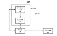
図4は、本発明の好適な一実施形態による自動ビデオ記録システムの第4実施形態を示すブロックダイアグラムを示している。図4の自動ビデオ記録システムは、ハウジング115内において一体的に統合されたカメラ46及び(好ましくは、パン及びチルト機能を内蔵する)位置決め器32を有する。基地局18は、図示のように、カメラ46及び位置決め器32に対して通信自在に結合されている。基地局18は、カメラ46及び位置決め器32を制御する。図4の自動ビデオ記録システムの構成の少なくとも1つの利点は、カメラの向きが位置決め器32との関係において固定されているという点にある。更に有利には、基地局18がハウジング115から物理的に分離されていることから、単一の基地局が、別個のユニットのその他のカメラ及び位置決め器を制御するように、構成されてもよい。
FIG. 4 shows a block diagram illustrating a fourth embodiment of an automatic video recording system according to a preferred embodiment of the present invention. The automatic video recording system of FIG. 4 includes a
本発明の好適な一実施形態によれば、1つのリモート装置を有する単一の被写体は、異なる角度から且つ/又は異なる場所において、複数のカメラによって撮影されてもよい。例えば、カメラ46及び位置決め器32を統合しているハウジング115は、異なる場所(例えば、サッカーフィールドに沿った又はスキースロープを下る複数の場所)において位置決めされてもよい。このような用途においては、単一の基地局が、リモート装置を追跡するように構成されたカメラのすべてを制御している。
According to a preferred embodiment of the present invention, a single subject with one remote device may be taken by multiple cameras from different angles and / or at different locations. For example, the
本明細書の別の好適な実施形態によれば、複数のカメラを使用することにより、別個のリモート装置を有する複数の被写体を撮影してもよく、この場合に、複数のカメラは、単一の基地局によって制御されている。図4に示されている複数のカメラ/位置決め器ユニットを有する実施形態においては、基地局は、それぞれのカメラ/位置決め器の場所だけでなく、それぞれのリモート装置の場所に関する情報をも受け取り、且つ、保存している。このような実施形態は、リゾート地やテーマパークなどの運営に有益であろう。更には、それぞれのプレーヤーごとにビデオ映像を生成することができることから、チームスポーツのスポーツコーチは、このようなシステムから利益を享受することになろう。 According to another preferred embodiment herein, multiple cameras may be used to capture multiple subjects with separate remote devices, where multiple cameras are a single Controlled by a base station. In the embodiment having multiple camera / positioner units shown in FIG. 4, the base station receives information regarding the location of each remote device as well as the location of each camera / positioner, and , Saving. Such an embodiment would be beneficial for the operation of resorts, theme parks and the like. In addition, team sports sports coaches will benefit from such a system because video footage can be generated for each player.
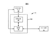
図5は、本発明の好適な一実施形態による自動ビデオ記録システムの第5実施形態を示すブロックダイアグラムを示している。図5の自動ビデオ記録システムは、ハウジング100内に一体的に統合された基地局18及び位置決め器32を有する。図5の自動ビデオ記録システムの少なくとも1つの利点は、様々なカメラと共に使用される柔軟性にある。図5の自動ビデオ記録システムは、基本的に、任意の接続されたカメラがハウジング100と適切に位置合わせされることにより、カメラの軸が、ハウジング100との関係において固定されると共に既知である方向に対して照準合わせするように、設計及び構築されなければならない。図5の自動ビデオ記録システムは、動力化されたパン位置決め器と、手動調節自在のチルト位置決め器と、を更に有してもよい。このような実施形態は、一定のチルトの維持が望ましい用途において有用である。
FIG. 5 shows a block diagram illustrating a fifth embodiment of an automatic video recording system according to a preferred embodiment of the present invention. The automatic video recording system of FIG. 5 includes a
図6は、本発明の好適な一実施形態による自動ビデオ記録システムの第6実施形態を示すブロックダイアグラムを示している。図6の自動ビデオ記録システムにおいては、パン位置決め器31とチルト位置決め器33は、別個に収容されている。基地局18及びパン位置決め器31は、ハウジング120内において一体的に統合されている。チルト位置決め器33とカメラ46は、ハウジング120内において一体的に統合されている。いくつかの用途においては、被写体の運動がパン運動のみによって追跡可能である場合には(例えば、垂直方向において、ほとんど運動が存在していない場合には)、ハウジング120をパン装置として使用するように選択すると共にカメラをハウジングに対して装着してもよい。いくつかのスポーツ活動(例えば、バンジージャンプ)のための専門的な実施形態は、カメラ46と統合された自動チルト位置決め器133を必要する場合がある。図6の自動ビデオ記録システムのようにコンポーネントを分離することにより、エンドユーザーが所望する機能(自動パン又は自動チルト)のみを有する装置を購入する柔軟性がエンドユーザーに対して提供される。
FIG. 6 shows a block diagram illustrating a sixth embodiment of an automatic video recording system according to a preferred embodiment of the present invention. In the automatic video recording system of FIG. 6, the
パン及びチルト運動について記述している際に、両方の位置決め器が動作中にある限り、そのシーケンス(順序)が反転可能であることに留意されたい。但し、位置決め器のうちの1つが欠けている場合には、結果的に得られるビデオ映像に、違いが観察されることになる。一定の傾斜が自動的なパンと組み合わせられている場合には、パン位置決め器が、傾斜軸との比較において、実質的に垂直方向の軸を中心として運動すると、カメラの運動は、異なったものとなる。実質的に垂直方向の軸の場合には、カメラは、特定の高度において被写体の水平方向の運動を追跡することになる。パン装置が傾斜している場合には、カメラは、傾斜のプレーン内に位置した方向において最小又は最大高度を有する運動を追跡することになる。 It should be noted that when describing pan and tilt motion, the sequence can be reversed as long as both positioners are in operation. However, if one of the positioners is missing, a difference will be observed in the resulting video image. When constant tilt is combined with automatic panning, the camera movement is different when the pan positioner moves about a substantially vertical axis compared to the tilt axis. It becomes. In the case of a substantially vertical axis, the camera will track the horizontal movement of the subject at a particular altitude. If the pan device is tilted, the camera will track the movement with the minimum or maximum altitude in the direction located in the plane of tilt.
図7は、図1の向きコントローラの好適な一実施形態のクローズアップ斜視図を示している。図7は、向きコントローラ100のフロントパネル130を示している。フロントパネル130は、好ましくは、図示のように、光源135を有する。向きコントローラ100は、好ましくは、図示のように、取付プラットフォーム140を有する。取付プラットフォーム140は、ボルト145により、向きコントローラ100のハウジング105に対して装着されている。ボルト145は、好ましくは、ウイングタイプのボルトである。ボルト145の端部は、好ましくは、ボルト145を回転させるのに十分な把持表面を提供している。取付プラットフォーム140は、ボルト145を回転させることにより、傾斜してもよい。
FIG. 7 shows a close-up perspective view of a preferred embodiment of the orientation controller of FIG. FIG. 7 shows the
取付プラットフォーム140は、好ましくは、カメラを取付プラットフォーム140に装着するための取付パッド165及び取付けねじ160を装備している。取付ねじ160は、好ましくは、大部分のカメラに対して接続可能なタイプである。大部分のカメラは、標準的な取付ねじ溝を有するが、いくつかのカメラは、異なる取付機能を有していても、まったく有していなくてもよい。非標準のカメラは、カメラ又はその他の装置を取付プラットフォーム140に接続するように構成されたアダプタを使用することにより、取付プラットフォーム140に対して接続されてもよい。
The mounting
取付プラットフォーム140の取付パッド165は、好ましくは、取付ねじ160が締め付けられた後に、接続されたカメラがプラットフォームとの関係において運動することを妨げるように設計された高摩擦パッドである。取付パッド165は、好ましくは、軟質シリコーンから製造されている。カメラ取付ねじ160を使用してカメラを取付プラットフォーム140に固定する前に、ユーザーは、カメラが適切に位置合わせされていることをチェックする必要がある。カメラが傾斜していない際に、カメラの光軸がフロントパネル130に対して垂直であれば、カメラは、向きコントローラ100と位置合わせされており、且つ、カメラを傾斜させることにより、その光軸は、フロントパネル130に対して垂直のプレーン内において運動することになる。ユーザーは、取付プラットフォーム140の位置合わせ特徴により、適切な位置合わせについてチェックしてもよい。位置合わせ特徴の好適な一実施形態は、フロントパネル130の対向する向きに対して平行である好ましくは矩形形状の取付プラットフォーム140のエッジ705である。このエッジとの間のカメラの位置合わせは、視覚的位置合わせによって実行されてもよい。カメラの形状に応じて、取付プラットフォーム140のフロントエッジ及びバックエッジを使用し、カメラを適切に位置合わせしてもよいことに留意されたい。
The mounting
図8は、図7の向きコントローラの取付プラットフォームを示す分解図を示している。 FIG. 8 shows an exploded view showing the mounting platform of the orientation controller of FIG.
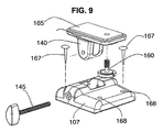
図9は、図1の向きコントローラの上部部分の一代替実施形態の分解図を示している。図9において、向きコントローラは、向きコントローラ100の下部部分(図示されてはいない)から分離可能であるキャップ107を有する。取付プラットフォーム140は、キャップ107上に取り付けられる。留め具167は、キャップ107を向きコントローラ100の下部部分に対して固定する。好ましくは、4つの留め具を使用し、キャップ107を向きコントローラ100の下部部分に固定する。図9の複雑化を回避するべく、好ましくは4つである留め具167のうちの2つのみが示されている。キャップ107が堅固に接続されている限り、その他の数の留め具でも十分であることに留意されたい。
FIG. 9 shows an exploded view of an alternative embodiment of the upper portion of the orientation controller of FIG. In FIG. 9, the orientation controller has a
それぞれの留め具は、好ましくは、キャップ107のアパーチャ168を通過する。アパーチャ168の位置決めは、キャップ107と向きコントローラ100の下部部分の位置合わせに有用である。上述のように、キャップ107と向きコントローラ100の下部部分の位置合わせは重要である。又、溝−隆起部のペア又は位置合わせピンなどのその他の幾何学的形状も、キャップ107と向きコントローラ100の下部部分の固定の際に使用されてもよい。
Each fastener preferably passes through the
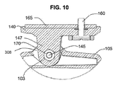
図10は、図7の断面A−Aにおける断面図を示している。図11は、図7の断面B−Bにおける断面図を示している。 FIG. 10 shows a cross-sectional view taken along the section AA of FIG. FIG. 11 shows a cross-sectional view taken along a section BB in FIG.
ボルト145は、図示のように、取付プラットフォーム140の下部部分の開口部を通過している。図示のように、ナット170がボルト145を固定している。ボルト145は、ハウジング105に対する取付プラットフォーム140の固定を支援する。更には、取付プラットフォーム140は、ボルト145の長手方向軸を中心として傾斜してもよい。
The
ボルト145は、好ましくは、ねじが切られたシャフト152を有する。ねじが切られたシャフト152は、好ましくは、組立体の幅の約5分の4にわたってのみ、延在している。ナット170は、好ましくは、図示のように、取付プラットフォーム140のハウジング係合部分147の内部表面内において固定されている。従って、図11に示されているように、ボルト145が締め付けられた際に、表面の1つのペア(取付プラットフォーム140の表面150とハウジング105の表面103)のみが、固定され、且つ、互いに圧接した状態において保持される。ナット170が内部的に固定されていることにより、ハウジング105から取付プラットフォーム140を取り外す際に除去する必要があるのは、単一のコンポーネントであるボルト145のみである。これは、少なくとも、本明細書のシステムは、屋外における使用が意図されているという理由から、有利であり、屋外における使用の場合には、小さな部品(ワッシャ、ナット、及びこれらに類似したもの)が失われやすい。
好適な一実施形態においては、ボルト145のねじが切られたロッド部分152及び把持部分162は、分離可能である。このような実施形態においては、把持部分162は、ねじが切られたロッド部分152の整合した矩形端部部分に嵌合する矩形の開口部を有してもよい。把持部分162及びねじが切られたロッド部分152は、好ましくは、オス−メス接続を介して1つに嵌合する。組立の後に、ユーザーは、ねじが切られたロッド部分152から把持部分162を簡単に取り外してもよい。潜在的な泥棒が、カメラ46を取付プラットフォーム140に固定するカメラ取付けねじ160にアクセスするために、ねじが切られた部分を緩める又は除去するための整合した形状を有するツールを必要とするようになることから、把持部分162を取り外すことにより、盗難抑止効果が得られる。
In one preferred embodiment, the threaded
好適な一実施形態においては、ねじが切られたロッド部分152及び把持部分162は、互いに、且つ、一体的に、永久的に付着されている。ボルト145がナット170を使用して取付プラットフォーム140と接続された後に、好ましくは、ボルト145を完全に緩めると共に取り外すことができないように、ボルト145の端部部分157は、組立の際に改造される。この結果、図10及び図11に示されている組立体のコンポーネントの分離と、部品の潜在的な消失と、が防止される。
In one preferred embodiment, the threaded
図10及び図11に示されている実施形態の1つの重要な特徴は、向きコントローラ100のハウジング105の上部部分の垂直方向の平坦な表面103が、フロントパネル130に対して垂直であるという点にある(図8を参照されたい)。更には、取付プラットフォーム140の下部部分147の垂直方向の平坦な表面150は、ボルト145の長手方向軸に対して垂直である。この特徴は、カメラ46が、正しい向きを有するように取付プラットフォーム140上において取り付けられると共に固定されている限り、向きコントローラ100との関係におけるカメラ46の向きが適切に方向付けされることを保証している。従って、取付プラットフォーム140上においてカメラ46を正しく取り付けることが非常に重要である。カメラ46は、カメラ46がフロントパネル130に対して垂直である方向において照準合わせするように、取付プラットフォーム140上に配置され、且つ、カメラ取付ねじ160を使用することにより、固定される。向きコントローラ100との関係におけるカメラの方向が記録セッションにおいて保持されることを確実にすることが重要である。これは、例えば、好ましくは、シリコンゴムなどの圧縮可能且つ高摩擦性の材料から製造された取付パッド165の支援により、実現される。カメラ取付ねじ160が固定された後に、カメラの方向は、カメラが向きコントローラ100によって運動するのに伴って、安定した状態に留まることになる。
One important feature of the embodiment shown in FIGS. 10 and 11 is that the vertical
カメラ46の取付けは、注意を必要とし、且つ、取付プラットフォーム140の矩形の形状によって支援される。好適な一実施形態においては、矩形形状の取付プラットフォーム140の長辺は、カメラ軸の意図された方向に対して平行である。この長辺は、取付プラットフォーム140上におけるカメラ46の視覚的位置合わせを支援する。但し、取付プラットフォーム140に正方形の形状を使用することも可能であり、或いは、カメラを位置合わせするために使用される辺がカメラ軸の意図された方向に対して平行である限り、矩形形状の短辺を使用することも可能である。
The mounting of the
矩形形状の取付プラットフォーム140のサイズは、好ましくは、ビデオカメラを支持するために十分な表面エリアを提供するように、十分に大きくなっている。例えば、30ミリメートル×60ミリメートルの矩形の上部面が使用されてもよいが、その他のサイズも十分であろう。相対的に重い又は嵩張るカメラを取り付ける場合には、相対的に大きな支持エリアが必要となろう。又、カメラの視覚的位置合わせを支援する溝又はマーキングなどの追加的な位置合わせ特徴が存在してもよい。
The size of the
別の実施形態においては、カメラの取付け方向の精度が光学セットアップ手順によって改善されている。上述のように、位置合わせが視覚的に正しいものとなるようにカメラが取り付けられたら、ユーザーは、壁のような平坦な垂直方向の表面に対してカメラを方向付けし、且つ、図8に示されている光源135を点灯する。光源135からの光ビームは、フロントパネル130に対して垂直である。ユーザーは、カメラを通じて垂直方向の表面上において光源135からの光のスポットを観察し、且つ、可視光がフレームの中心において出現するように、取付プラットフォーム140上においてカメラ46の位置合わせを調節する。ユーザーは、カメラ46のズームを変更してもよく、且つ、存在する場合には、光スポットの運動を観察してもよい。カメラ46が適切に方向付けされている場合に、光は、ズームしている間にフレーム内において運動せず、相対的に小さく又は大きく、或いは、相対的に鋭く又は拡散した状態で、出現することになる。光スポットがフレームの側部まで運動した場合には、カメラ軸は、光源135からの光とビームと平行ではなく、且つ、カメラ46を調節する必要がある。この手順は、カメラ46が正しく取り付けられていることにユーザーが満足する時点まで、反復される。
In another embodiment, the accuracy of the camera mounting direction is improved by an optical setup procedure. As described above, once the camera is mounted so that the alignment is visually correct, the user orients the camera against a flat vertical surface, such as a wall, and in FIG. The illustrated
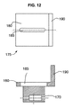
図12は、本発明の好適な一実施形態によるカメラ取付プラットフォームの一代替実施形態を示す平面図及び対応する断面図を示している。図13は、本発明の好適な一実施形態によるカメラ取付プラットフォームの別の代替実施形態を示す平面図及び対応する断面図を示している。 FIG. 12 shows a plan view and corresponding cross-sectional view illustrating an alternative embodiment of a camera mounting platform according to a preferred embodiment of the present invention. FIG. 13 shows a plan view and corresponding cross-sectional view of another alternative embodiment of a camera mounting platform according to a preferred embodiment of the present invention.
図12は、(カメラ取付プラットフォーム140に代わる)カメラ取付プラットフォーム175を示している。カメラ取付プラットフォーム175は、カメラ取付プラットフォーム140が装着されるのと同一の方式により、ハウジング105に装着される(図8を参照されたい)。カメラ取付プラットフォーム175は、好ましくは、図12に示されているサイドパネル190又は図13に示されているバックパネル195を有する。カメラは、図8〜図11に示されているカメラ取付ねじ160を使用することにより、水平方向の表面180上に固定される。図12に示されている取付プラットフォームは、実質的にカメラの光軸に沿って細長い形状を有すると共にカメラの光軸に対して平行である少なくとも1つの平坦な側部を有するカメラの取付けを許容するように設計されている。開口部185は、カメラ取付ねじ160の通過を許容する。開口部185は、様々な幅を有する様々なカメラタイプの取付けに対応するように、細長くなっている。図12において、サイドパネル190に当接するようにカメラ46を取り付けることにより、カメラ軸の適切な位置合わせが保証される。
FIG. 12 shows a camera mounting platform 175 (instead of the camera mounting platform 140). The
その光軸に対して実質的に垂直である細長い形状と、カメラ軸に対して垂直である実質的に平坦な背面と、を有するカメラの場合には、好ましくは、図13に示されているプラットフォームが使用される。開口部185は、取付ねじ160の通過を許容し、且つ、所定範囲のカメラの厚さに対応するように、細長くなっている。取り付けられたカメラの背面がプラットフォーム175のバックパネル195に当接した場合に、取り付けられたカメラの適切な位置合わせが実現されている。
In the case of a camera having an elongated shape that is substantially perpendicular to its optical axis and a substantially flat back surface that is perpendicular to the camera axis, it is preferably shown in FIG. A platform is used. The
いくつかの実施形態においては、カメラ取付プラットフォームのチルト機能が省略されてもよいことに留意されたい。このような実施形態においては、カメラ取付プラットフォームは、一定の傾斜を有するように製造されてもよく、或いは、まったく傾斜を伴わないように製造されてもよい。 Note that in some embodiments, the tilt function of the camera mounting platform may be omitted. In such embodiments, the camera mounting platform may be manufactured with a constant tilt or may be manufactured with no tilt at all.
リモート装置16は、本発明の自動ビデオ記録システムのすべての実施形態の重要なコンポーネントである。リモート装置16は、それ自身の場所を検出することにより、或いは、リモート装置16と関連付けられた被写体12の場所を検出するように基地局18を支援することにより(例えば、図2を参照されたい)、カメラ46を被写体12に対して方向付けすることを支援する。これらのタスクは、リモート装置16が様々な入力及び出力機能を有することを必要としている。更には、リモート装置16が、自動ビデオ記録システムの状態、ユーザーフィードバック、及びシステムの遠隔制御に関する情報を提供することが望ましい。リモート装置16のユーザーフィードバック及び遠隔制御機能は、好ましくは、複数の方式(例えば、光及び音響信号、プッシュボタン、タッチスクリーン、又は音声入力など)によって実装される。リモート装置16は、通常、屋外環境において被写体12によって担持されることから、リモート装置16は、好ましくは、防水性及び耐衝撃性を有する。
The
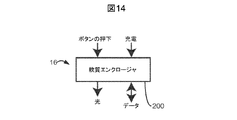
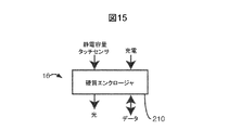
図14は、本発明の好適な一実施形態によるリモート装置の第1実施形態を示す概略図を示している。図15は、本発明の好適な一実施形態によるリモート装置の第2実施形態を示す概略図を示している。図14及び図15は、リモート装置の好適な実施形態において可能にされる主要な入力及び出力接続を示している。 FIG. 14 shows a schematic diagram illustrating a first embodiment of a remote device according to a preferred embodiment of the present invention. FIG. 15 shows a schematic diagram illustrating a second embodiment of a remote device according to a preferred embodiment of the present invention. FIGS. 14 and 15 show the main input and output connections made possible in the preferred embodiment of the remote device.
図14は、軟質エンクロージャ200を有するリモート装置16の第1実施形態を示している。図15は、硬質エンクロージャ210を有するリモート装置16の第2実施形態を示している。いずれの実施形態も、好ましくは、無線及び電気データによる入力と、無線、光、及びデータ通信による出力と、を可能にする。更には、いずれの実施形態も、好ましくは、関連付けられた電池の充電を可能にする。エンクロージャ(軟質エンクロージャ200及び硬質エンクロージャ210)は、いずれも、好ましくは、完全に閉鎖されたポリマーエンクロージャである。両方の実施形態の重要な特徴は、エンクロージャが、リモート装置の動作のために不可欠である封入された電気回路を短絡させないように、完全に閉鎖されたポリマーエンクロージャが、大きな電気抵抗値を有するという点にある。又、使用されるポリマーも、好ましくは、高周波における低減衰特性を有する。更には、使用されるポリマーは、好ましくは、低熱伝導率をも有する。大きなエネルギーを消費する回路の場合には、低熱伝導率は、問題となる場合がある。この問題点は、電気設計上における対策により、部分的に、且つ、大きな電気抵抗値と中程度の熱伝導率の両方を有する複合ポリマーを使用することにより、部分的に、解決される。例えば、いくつかのシリコーンに基づいた複合材料は、1.5〜7W/mKという熱伝導率を有し(比較を目的として、ポリウレタンの熱伝導率は、約0.02W/mKであり、鋼の熱伝導率は、16〜45W/mKである)、同時に、これらは、1014Ω・cm超という抵抗率を有することができる。
FIG. 14 shows a first embodiment of a
データ転送は、無線トランシーバにより、或いは、電池充電の環境において後述するものに類似した設計により、実装されてもよい。相違点は、電池充電用の充電スタブの代わりに、データワイヤ接点のアレイが露出しているという点にある。これらの接点は、セキュアデジタルカード又はSDカードと呼ばれるメモリカードにおいて使用されているものに類似したものであってもよい。接点は、好ましくは、内部回路により、水中における短絡から保護されている。 Data transfer may be implemented by a wireless transceiver or by a design similar to that described below in a battery charging environment. The difference is that instead of a charging stub for charging the battery, an array of data wire contacts is exposed. These contacts may be similar to those used in memory cards called secure digital cards or SD cards. The contacts are preferably protected from short circuits in water by internal circuitry.
図14及び図15に示されている実施形態の間の少なくとも1つの相違点は、軟質ポリマーエンクロージャの薄い層によってカバーされたスイッチをユーザーの指によって動作させてもよいという点にある。硬質エンクロージャは、例えば、タッチスクリーンなどの大きな硬質要素の周りに相対的に優れた防水性エンクロージャが製造されるという点において、有利である。 At least one difference between the embodiments shown in FIGS. 14 and 15 is that a switch covered by a thin layer of soft polymer enclosure may be operated by a user's finger. A rigid enclosure is advantageous in that a relatively good waterproof enclosure is produced around a large rigid element such as, for example, a touch screen.
硬質エンクロージャ210を有すると共にタッチスクリーンを更に有するリモート装置16の好適な実施形態においては、オン/オフ機能は、常にオン状態にある静電容量性タッチセンサによって実装される。例えば、装置をターンオン又はターンオフするには、同時に両方のエリアにおいて、2つのエリアセンサに対して少なくとも5秒間にわたって接触しなければならない。
In a preferred embodiment of the
図16A〜図16Dは、本発明の好適な一実施形態によるリモート装置の4つの実施形態変形例を示す概略断面図を示している。図16A〜図16Dに示されているリモート装置16の実施形態は、軟質及び硬質エンクロージャが様々な組合せにおいて使用されている実施形態変形例を示している。図16Aにおいては、リモート装置16は、図示のように、硬質エンクロージャ230に埋め込まれた軟質エンクロージャ220に埋め込まれたリモート装置16の電気的及び電気機械的コンポーネントを有する。図16Bにおいては、リモート装置16は、軟質エンクロージャ240に埋め込まれた硬質エンクロージャ250に埋め込まれたリモート装置16の電気的及び電気機械的コンポーネントを有する。
16A-16D show schematic cross-sectional views illustrating four embodiment variations of a remote device according to a preferred embodiment of the present invention. The embodiment of the
図16C及び図16Dの実施形態は、図示のように、電子的及び電気機械的コンポーネントを軟質エンクロージャ260又は硬質エンクロージャ290に完全に埋め込み、且つ、第2の分離可能な部分である硬質エンクロージャ270又は軟質エンクロージャ280を提供することにより、構築されている。
The embodiment of FIGS. 16C and 16D, as shown, fully embeds the electronic and electromechanical components in the
図16Cに示されている実施形態は、耐衝撃性を有し、その理由は、軟質エンクロージャ260の機械的保護を提供する外側硬質エンクロージャ270に軟質ポリマー260が埋め込まれているからである。更には、外側の硬質エンクロージャ270の使用により、例えば、装置をストラップ又はベルトに装着することが可能になる。この好適な設計バージョンの特定の例が、図17A及び図17Bに示されている。
The embodiment shown in FIG. 16C is impact resistant because the
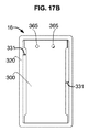
図17A及び図17Bは、本発明の好適な一実施形態によるリモート装置を示す正面図及び背面図を示している。図17Aのリモート装置は、本発明の好適な実施形態による防水性及び耐衝撃性エンクロージャを有するように製造された電子装置の特定の例である。図17Aは、リモート装置16の正面を示しており、図17Bは、リモート装置16の背面を示している。
17A and 17B show a front view and a rear view of a remote device according to a preferred embodiment of the present invention. The remote device of FIG. 17A is a specific example of an electronic device manufactured with a waterproof and impact resistant enclosure according to a preferred embodiment of the present invention. FIG. 17A shows the front of the
リモート装置16の可視部分は、リモート装置16の電子的及び電気機械的コンポーネントを完全にカプセル化するソフトポリウレタンモールド体300を含み、唯一の例外が、アクリル光導体の端部345及びステンレス鋼充電スタブの端部365である。軟質ポリウレタンモールド体300は、嵌合表面330において、硬質の好ましくは射出成形されたABSプラスチックフレーム320内にしっかりと嵌合されている。モールド体300とフレーム320の間には、ギャップ331が存在しており、このギャップは、ストラップを通すために使用されてもよく、ストラップは、装置を被写体の身体に対して、又はスポーツ用機器に対して、又はこれらに類似したものに対して、装着するために使用されてもよい。軟質ポリウレタンモールド体300の内部に埋め込まれたマイクロスイッチが、わずかに隆起しており、且つ、モールド体表面の隆起表面350として可視状態にある。
The visible portion of the
モールド体300用の材料の選択肢は、軟質ポリウレタンであるが、適切な代替肢によって代用してもよい。軟質ポリウレタンモールド体300又は任意の代用材料は、大きな水接触角を有すると共に疎水性を有するべきである。約100度の又はこれを上回る水接触角を有する材料が撥水材料として好ましい。軟質ポリウレタンの機械的特性(40ショアA〜10ショアAの範囲の硬度)が優れており、類似の特性を有するその他のプラスチックも同様に使用されてもよい。
The material choice for the
フレーム320用の好適な材料は、ABSプラスチック(75ショアA超の硬度)であり、その他の類似の材料も同様に可能であろう。軟質及び硬質モールド体が組合せにおいて使用される際には、図16A及び図16Bに示されているように、硬質ポリウレタンが、硬質エンクロージャ用の好適な選択肢である。図16Aに示されている実施形態においては、リモート装置のフロント部分は、軟質であるが、装置の背面は、硬質ポリウレタンである。図16Aの実施形態においては、フレーム320が省略されており、その理由は、その機能が、硬質ポリウレタン部分に統合されてもよいからである。ウォータースポーツ活動において使用される電子製品の場合には、プラスチックなどの軽量材料の使用が好ましいが、いくつかの用途においては、金属も同様に使用可能であろう。
A suitable material for the
図17A及び図17Bに示されているリモート装置16用の設計は、例えば、サーファなどの腕又は足首に装着された状態において着用可能な電子製品の場合に、好適である。ストラップ又はバンドは、軟質ポリウレタンモールド体300とフレーム320の間に存在するギャップを通過する。図面に示されている例は、自動ビデオ記録システムのリモート装置に固有のものではあるが、本明細書に開示されている原理は、様々な電子製品に適用可能である。
The design for the
図17A及び図17Bに示されている好適な設計においては、モールド体300は、フレーム320内にしっかりと嵌合されている。フレーム320の装着のセキュリティを改善するために、フレーム320は、好ましくは、表面330のフロントエッジ及びバックエッジにおけるわずかな隆起部である「リップ」を有するように設計される。モールド体300をフレーム320と組み立てるには、モールド体300の軟質ポリウレタンの圧縮性を活用する。或いは、この代わりに、モールド体300とフレーム320は、接着剤を使用することにより、又は溶剤接合を使用することにより、永久的に1つに接合されてもよい。更には、舌及び溝形状を利用し、接合を支援してもよい。類似の方式により、成形されたコアと射出成形されたフレームの間における緊密な嵌合を許容する圧縮スプリングとして蓋なしモールド体のメニスカスを使用することができる。
In the preferred design shown in FIGS. 17A and 17B, the
図18は、本発明の好適な一実施形態によるリモート装置に埋め込まれたマイクロスイッチを示す断面図を示している。図18の実施形態においては、リモート装置16は、好ましくは、軟質ポリウレタンモールド体300の内部において完全に固定されたマイクロスイッチ及び類似の装置を利用している。例示用のマイクロスイッチ310の上部部分370は、軟質ポリウレタンモールド体300の内部において示されている。マイクロスイッチ310のボタン380は、その上方の隆起したポリウレタン表面350に対して最も近接した部分である。マイクロスイッチ310の上部部分370は、好ましくは、中空シリンダの形態において成形された閉鎖されたセル発泡体部分395内において固定されている。第2のワッシャ形状の閉鎖されたセル発泡体部分305が、ボタン380に隣接した状態において位置決めされている。ボタン380の運動が妨げられないように、閉鎖されたセル発泡体部分305及び395を使用し、マイクロスイッチ310のボタン380をモールド体300から分離している。閉鎖されたセル発泡体材料は、製造の容易性及び圧縮性のために好ましいが、ボタン380と閉鎖されたセル発泡体部分305の間においてほとんど又はまったく摩擦を生成しない任意の高圧縮性材料が適切に利用されてもよい。薄い曲がり易いシート390が組立体を閉鎖している。マイクロスイッチボタン380の最上部は、リモート装置16の前部の表面315を形成する成形レベルに対して近接した状態において配置されている(約1〜約4ミリメートル)。この結果、モールド体は、マイクロスイッチのエリア内においてわずかに隆起しており、且つ、結果的に得られる隆起した表面350は、ユーザーにとって明らかに弁別可能である。約1〜約4ミリメートルというモールド体の厚さの範囲は、マイクロスイッチ310の便利な取り扱いを許容する。閉鎖されたセル発泡体材料は、上述のように使用されてもよく、或いは、これは、成形されてもよい。
FIG. 18 shows a cross-sectional view of a microswitch embedded in a remote device according to a preferred embodiment of the present invention. In the embodiment of FIG. 18, the
リモート装置16などの電子装置のユーザーにとっては、その装置の又は電子装置が通信している装置の状態について通知されることが重要である。このような情報を提供する1つの好適な方法は、発光ダイオード(LED)又は類似の装置によるものである。表面315に近接した状態においてモールド体300に埋め込まれたLEDを有することができる。多くのポリウレタンと同様に、モールド体300が半透明である場合には、LED光は、弱くなるが、可視状態となる。
It is important for a user of an electronic device such as
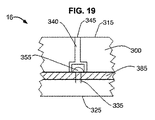
図19は、本発明の好適な一実施形態によるリモート装置内の光導体を有する埋め込まれた光源を示す断面図を示している。図19は、印刷回路基板385内において固定されると共に上部表面315に向って照準合わせしたLED355を示している。LEDリード線335は、好ましくは、印刷回路基板385の裏面上において印刷回路基板385に対してはんだ付けされている。光導体340は、図示のように、LED355の上部において固定されている。モールド体300は、印刷回路基板385を完全に取り囲んでいる。好適な一実施形態においては、成形は、前面315が光導体340の最上部345と同一平面上に位置するように、実行される。LED用の光導体は、光学グレードのアクリル、ポリカーボネート、又はポリブチレンなどの様々な材料から製造される。又、光導体は、異なる形状を有してもよい。好ましくは、光導体用の選択された材料は、モールド体に対する良好な接着性を有し、且つ、疎水性を有する。又、光導体340は、カラーフィルタとして機能してもよい。一代替実施形態においては、光導体340の最上部345は、ドーム形状を有している。このような好適な実施形態は、側部から観察された際に、LED光の改善された可視性を提供するという利点を有する。
FIG. 19 shows a cross-sectional view of an embedded light source having a light guide in a remote device according to a preferred embodiment of the present invention. FIG. 19 shows the
図20は、本発明の好適な一実施形態によるリモート装置内の埋め込まれた電気接続ポストを示す断面図を示している。更に詳しくは、図20は、リモート装置16の充電スタブ360を示している。充電スタブ360は、好ましくは、印刷回路基板385上のはんだ付けリムにはんだ付けされた導体から製造されている。はんだ375は、図示のように、印刷回路基板385の片面上にあってもよく、或いは、基板の両面上にあってもよい。好適な一代替実施形態においては、充電スタブ360は、はんだ付けを伴うことなしに、印刷回路基板385上の縁部が付与された孔に圧入される。充電スタブ360は、好ましくは、充電スタブの端部365を除いて、モールド体300によって完全に取り囲まれている。充電スタブ360の端部365は、好ましくは、表面325と同一平面上に位置している。充電スタブ360の端部365は、(リモート装置16の電池を充電するための)充電器と結合し、充電器は、好ましくは、標準的な家庭用電気コンセント回路に接続される。
FIG. 20 shows a cross-sectional view of an embedded electrical connection post in a remote device according to a preferred embodiment of the present invention. More specifically, FIG. 20 shows the charging
充電スタブ360は、好ましくは、成形材料に対する良好な接着性を有しており、且つ、疎水性を有する耐腐食性材料から製造される。充電スタブの材料の好適な一例は、電解研磨された表面を有するグレード304のステンレス鋼である。材料の選択肢に応じて、充電スタブ360の印刷回路基板385に対する接合は、溶接プロセス(例えば、スポット溶接)を使用することにより、実行されてもよい。充電スタブ360がはんだ付け不能な金属から製造されている場合には、例えば、はんだ付けを促進する亜鉛などの被覆によって被覆されてもよい。別の好適な実施形態においては、充電スタブ360は、印刷回路基板385に、はんだ付けされてはおらず、且つ、圧入によって充電スタブ360との電気的接触が提供されている。
The charging
好適な一実施形態においては、リモート装置16用の充電器は、充電スタブ360に接続するための平坦な又は凸状の形状の磁気充電パッドを装備している。又、一実施形態においては、充電スタブ360も、磁性を有しており、且つ、充電器の充電パッドと充電スタブ360の間の磁力により、電子装置(リモート装置16)と充電器が1つに保持される。このような実施形態においては、磁力は、電子装置が充電器に対して誤った方式で接続されることをも防止する。別の好適な実施形態においては、充電スタブ360は、強磁性を有しているが、磁化されてはいない。充電器の磁気充電パッドと強磁性充電スタブ360の間の磁力は、充電の際の接触を保証することになり、好ましくは、機械的設計により、正しい極性が保証される。更に別の好適な実施形態においては、充電スタブ360は、銅、アルミニウム、真鍮、又は非磁性ステンレス鋼などの非磁性金属から製造されている。充電器の充電パッドと充電スタブの間の電気的接触は、例えば、スプリングにより、或いは、充電器内の少なくとも1つの磁石とモールド体300内の1つの強磁性プレート又は磁石の間の磁力により、提供される。図20(並びに、端部365が可視状態にある図17B)に示されている充電スタブ360の円筒形の形状は、自動ビデオ記録システムのリモート装置の充電スタブの場合に、好適なものであり、(例えば、データ接点などの)その他の用途の場合には、その他の設計が実現可能であろう。
In one preferred embodiment, the charger for
標準的なビデオ記録においては、音響は、ビデオレコーダ自体によって記録される。本発明の自動ビデオ記録システムの場合には、この音響記録の方法は、多くの場合に、最適なものではなく、その理由は、記録されている動作が、カメラの近傍に位置してはおらず、且つ、コメントを提供するカメラマンが存在していないからである。むしろ、記録の被写体12、即ち、自動ビデオ記録システム10のリモート装置16を有する人物(図1を参照されたい)が、コメントの記録を所望することになる。向きコントローラ70のモーター及びギアが雑音を生成する場合には、カメラ46は、その雑音を記録することになる。更には、自動ビデオ記録システム10のカメラ46が記録に無関心なその他の人物の近傍に存在しており、且つ、カメラが彼らの無関係な会話又はコメントを記録することになる可能性も高いであろう。これらのすべての理由から、カメラ46によって記録される音響を被写体12によって記録されるサウンドトラックによって置換することが望ましい。これは、被写体12と一緒に配置されたリモート装置16内にマイクロフォンなどの音声検知装置を提供することにより、実現される。本発明の好適な一実施形態においては、リモート装置16は、1つ又は複数の音声又は音響検知装置を含む。更には、リモート装置16は、記録された対応するビデオに後から埋め込むべく音響を電子的に記録及び保存し、或いは、記録、保存、及び/又は同期化のために音響情報を送信する能力を有してもよい。
In standard video recording, sound is recorded by the video recorder itself. In the case of the automatic video recording system of the present invention, this acoustic recording method is not optimal in many cases because the recorded action is not located in the vicinity of the camera. This is because there is no photographer who provides comments. Rather, the
音声指示を記録すると共に向きコントローラ100に送信するためにリモート装置16を使用する権限を被写体12に対して付与することに大きな利点が存在している。音声指示の使用は、身体的な要求事項が多いスポーツ活動においては、プッシュボタン又はタッチスクリーン入力などの代替肢よりも格段に容易であると共に効率的であろう。
There is a significant advantage in granting the subject 12 the authority to use the
図21は、本発明の好適な一実施形態によるマイクロフォン及びスピーカを装備したリモート装置の主要コンポーネントを示す概略図を示している。リモート装置16の場所は、好ましくは、測位システムから衛星信号20(又は、等価な地上信号)を受け取る全地球測位アンテナ22によって判定される。このような測位システムの一例は、全地球測位システム(Global Positioning System:GPS)である。或いは、この代わりに、その他の場所判定技術が利用されてもよい(このような実施形態においては、リモート装置16のいくつかのコンポーネントは、使用されている場所判定システムと結合されるコンポーネントによって置換されることになろう)。全地球測位アンテナ22が受け取ったデータは、マイクロコントローラ/メモリユニット66及び無線トランシーバ24に伝達される。制御ボタン72及び74は、好ましくは、リモート装置16の電源を投入及び切断するために、且つ、その他の機能のために、含まれている。状態インジケータLED84は、好ましくは、システムの準備完了状態を示している。電池、充電器接点、及び充電インジケータLEDは、リモート装置16のその他の好適なコンポーネントであるが、図21には、示されていない。リモート装置16は、好ましくは、図示のように、マイクロフォン80と、スピーカ87と、を有する。
FIG. 21 shows a schematic diagram illustrating the main components of a remote device equipped with a microphone and speaker according to a preferred embodiment of the present invention. The location of the
マイクロフォン80は、電子信号をマイクロコントローラ/メモリユニット66及び無線トランシーバ24に出力する。無線トランシーバ24は、先程の図1〜図6に更に広範に示されている自動ビデオ記録システム10の基地局18との間の双方向通信(50及び52)のために使用される。参照符号50及び52によって示されている双方向通信は、好ましくは、高周波を介したものである。基地局18及びリモート装置16内の無線トランシーバは、好ましくは、それぞれの記録セッションごとに、ペア化される。ペア化の結果として、無線通信データパケットは、好ましくは、同一の近傍領域内において動作している関係のないトランシーバによる干渉を回避するべく、識別子コードによって先行されている。図21に示されている実施形態においては、全地球測位アンテナ22を用いて取得された位置データは、基地局18に送信されており、基地局18は、関連付けられたカメラをリモート装置16の方向において方向付けするように、1つの位置決め器(又は、複数の位置決め器)に対して指示している。リモート装置16は、好ましくは、例えば、一人のサーファが別のサーファに容易に伝達することができるように、容易に受け渡し可能な装置である。自動ビデオ記録システム10のカメラ46は、誰がリモート装置16を保有していても、その人物を追跡及び記録する。
The
好適な一実施形態においては、基地局18は、カメラ46の「オン/オフ」、「記録/記録の停止」、及びその他の機能を制御することができる。このタイプの制御により、記録のターゲット又は被写体は、リモート装置16と基地局18の間の通信機能を使用して記録の様々な側面を制御してもよい。制御は、ボタンスイッチ又はタッチセンサを物理的に係合させることにより、実行してもよく、或いは、その代わりに、音声により、実行してもよい。例えば、サーファは、波に向って手でかき進み始めた際に、「記録」という言葉を発話することが可能であり、且つ、記録の停止を所望する際に、「停止」と発話することができる。この機能は、被写体が実際にサーフィンしている部分(この長さは、わずかに数分間であってもよい)を見出すために数時間に及ぶサーフィンビデオを閲覧する必要性を除去するという点において、有利である。別の実施形態においては、ユーザーは、一連の高品質のスチール画像を取得するように、カメラに対して指示を送信してもよい。
In a preferred embodiment, the
好適な一実施形態においては、音響は、リモート装置16において記録されると共に基地局18に送信され、且つ、キャプチャされたビデオと同期化される。送信されるオーディオ情報は、オーディオ情報パケットに分割される。それぞれのオーディオ情報パケットは、タイムスタンプが付与され、且つ、基地局18に送信される。基地局18は、オーディオ情報パケットが送信の際に壊れていないことを検証し、且つ、オーディオ情報パケットが正しく受信されていることについてリモート装置16との間において通信する。オーディオ情報パケットが壊れていた場合には、基地局18は、壊れていると基地局18が指定したオーディオ情報パケットを再送するように、リモート装置16に対して伝達する。オーディオ情報パケットは、タイムスタンプ情報を使用することにより、記録されたビデオにおける適切な時刻に対してマッチングされる。このプロセスは、自動ビデオ記録システムが動作している間、反復される。基地局18は、リモート装置16と通信し、送信されたオーディオ情報パケットのすべてを基地局が受け取ったことを検証する。いずれかのオーディオ情報パケットが基地局18によって受け取られていない場合には、基地局18は、いずれの期間が失われているのかをリモート装置に伝達し、且つ、それらのタイムスタンプに対応するオーディオ情報パケットがリモート装置16から基地局18に再送される。以上は、自動ビデオ記録システムとの関係において説明されているが、このプロセスは、オーディオ情報が記録装置とは別個の装置によってキャプチャされるあらゆる用途に適用可能である。
In one preferred embodiment, the sound is recorded at the
本発明の別の好適な実施形態においては、オーディオ情報パケットの基地局18に対する送信に加えて、記録された音響ファイルの複写がリモート装置16において保存されている。リモート装置16における記録されたオーディオの保存は、リモート装置16と基地局18の間の通信リンクが危険に晒されている場合にリモート装置16からのオーディオをバックアップとして使用してもよいという点において、有益である。
In another preferred embodiment of the present invention, in addition to transmitting audio information packets to the
被写体12が制御を所望する場合がある基地局18のその他の機能が存在している。例えば、リモート装置16を使用することにより、カメラ46の向きを調節又は再較正するように、位置決め器32を制御することができよう。このような制御は、適切なボタンを押下することにより、或いは、リモート装置16において埋め込まれたタッチスクリーンとやり取りすることにより、実行されてもよい。更には、且つ、非常に好ましくは、このような制御は、操作に手を使わないで済むように、音声によって作動させてもよい。
There are other functions of the
位置決め器32は、好ましくは、望ましくない音響を生成する場合のある電子的及び機械的コンポーネント(例えば、モーターやギアボックスなど)と関連する雑音を低減するように設計されている。これは、雑音の遮蔽、物理的な減衰、及び/又は雑音吸収材料を位置決め器32又はカメラ向きコントローラ100に内蔵することによって実現される。これらの設計における対策は、機器の原価及び重量を増大させる場合があるが、音響がカメラ46によって記録される場合には、有用である。被写体12によって記録された音響トラックを提供することにより、位置決め器又はカメラ向きコントローラと関連する雑音問題の処理の必要性が低減される。それにも拘わらず、カメラ46による音響の検知及び記録は有用であろう。例えば、カメラを動作させるべくカメラマンが必要とされない場合にも、カメラの近傍の友人が記録に関する定期的なコメントの付与を所望する場合がある。
The
又、基地局18が別個の場所に存在している場合には、基地局18によって音響を記録することも有用であろう(例えば、図4を参照されたい)。このような実施形態においては、いくつかのカメラ及びいくつかのリモート装置が単一の基地局によって制御されてもよい。基地局18は、すべてのカメラによる記録を監督すると共に有意なコメントを記録に対して付加する操作者により、制御されることになろう。関係する一実施形態においては、基地局18に位置した人物は、リモート装置16を通じて追跡されている被写体12に対して通信してもよい。この実施形態においては、基地局18及びリモート装置16は、好ましくは、無線による一方向又は双方向の音声通信を有する。
It may also be useful to record sound by the
本明細書の好適な一実施形態によれば、リモート装置16は、防水性及び耐衝撃性を有する。上述のように、このような防水性及び耐衝撃性は、(電子的、電気的、又は光学的なインターフェイス及びタッチスクリーンを提供するために露出する必要がある表面を除いて)リモート装置のコンポーネントをポリマーに埋め込むことにより、実現される。このような実施形態においては、ポリマーは、内側表面と、外側表面と、を有する。内側表面は、好ましくは、リモート装置ユニットの電子的及び機械的部分と直接接触している。ポリマーの外側表面は、リモート装置の表面の一部であり、且つ、リモート装置の化粧表面として部分的に機能してもよい。又、リモート装置の外側表面は、電気的又は電子的接触の表面、光導体の表面、レンズ、及び画面の表面、タッチスクリーン、及びこれらに類似したものをも含む。又、外側表面は、マイクロフォン及びスピーカの表面を含むこともできる。
According to a preferred embodiment of the present specification, the
従来の防水は、カメラなどの装置がその内部に収容される硬質ポリマーのシェル又はケースの使用を利用していることに留意されたい。このようなエンクロージャと保護された装置の間における空気の音響絶縁特性に起因し、このようなエンクロージャ内の装置は、音響の記録にあまり適してはいない。同時に、このような硬質エンクロージャは、ユーザーによって着用された衣服と擦れることにより、且つ、その他の硬質物体に衝突することにより、音響を生成する。リモート装置を、例えば、軟質ポリウレタンなどの軟質ポリマーに埋め込むことにより、これらの問題点が低減又は解決される。軟質ポリマーを使用することにより、ユニットの衝撃抵抗力が改善され、且つ、ユニットが硬質物体に衝突した際に生じうる音響が低減される。埋め込みポリマーは、被写体によって着用された衣服がユニットの本体と擦れた際に生成されるものなどの局所的に生成される音響の伝播を低減する。これらの機能は、その他の音響記録装置に対して適用可能である。例えば、着用可能な着脱自在のカメラなどの電子装置に伴う又はその他の方式によってこれらの装置と共に内蔵されうるマイクロフォンによって記録される音響も、これらの電子装置をポリマーに、特に、相対的に低硬度のポリマーに、埋め込むことにより、同様に改善することができる。 Note that conventional waterproofing utilizes the use of a rigid polymer shell or case in which a device such as a camera is housed. Due to the acoustic insulation properties of the air between such an enclosure and the protected device, the device in such an enclosure is not well suited for acoustic recording. At the same time, such a hard enclosure generates sound by rubbing against clothes worn by the user and by impacting other hard objects. By embedding the remote device in a soft polymer such as, for example, soft polyurethane, these problems are reduced or solved. By using a soft polymer, the impact resistance of the unit is improved and the sound that can occur when the unit collides with a hard object is reduced. The embedded polymer reduces the propagation of locally generated sound, such as that generated when the garment worn by the subject rubs against the unit body. These functions can be applied to other acoustic recording apparatuses. For example, the sound recorded by a microphone that can accompany or otherwise be incorporated with these devices, such as wearable removable cameras, also makes these electronic devices polymer, especially relatively low hardness The same improvement can be achieved by embedding in the polymer.
本明細書の本発明の原理を使用する用途の一例は、「リアリティ」テレビショーなどのテレビショーの撮影を含む。本明細書のシステムを使用し、シーンを妨げることなしに(又は、複数の撮影班の支出を伴うことなしに)、混雑したエリア内においてシーンを撮影してもよい。一人又は複数のリアリティテレビの被写体は、すべての映像及びイベントが、その発生に伴ってキャプチャされるように、マイクロフォンを有するリモート追跡装置を着用する。カメラは、単一の被写体又は複数の被写体或いはこれらのなんらかの組合せを追跡するべく、異なる角度及び高度においてセットアップされてもよい。音声記録にタイムスタンプを付与し、後からの編集及び制作のために、それらの音声記録を記録されている画像とマッチングしてもよい。 An example of an application that uses the inventive principles herein is in the shooting of a television show, such as a “reality” television show. The system herein may be used to film a scene in a congested area without interfering with the scene (or without the expense of multiple film crews). One or more reality television subjects wear a remote tracking device with a microphone so that all video and events are captured as they occur. The camera may be set up at different angles and altitudes to track a single subject or multiple subjects or any combination thereof. Time stamps may be added to the audio recordings, and those audio records may be matched with the recorded images for later editing and production.
図1〜図6は、スポーツイベントの参加者などの被写体12の場所を検出すると共に被写体12を追跡するように構成された自動ビデオ記録システム10を示している。好ましくは、自動ビデオ記録システム10は、好ましくは、被写体12と一緒に配置されたリモート装置16、基地局18、位置決め器32、及びカメラ46を有する。基地局18及びリモート装置16は、好ましくは、マイクロコントローラと、通信装置と、を有する。基地局18は、カメラ46の場所において取得されたセンサデータに部分的に基づいて、カメラ46とリモート装置16の間の照準ベクトル48を判定する。更なる詳細については、先程引用によって本明細書に包含された第’203号特許出願明細書を参照されたい。被写体12がリモート装置16と共に運動するのに伴って、照準ベクトル48が更新され、且つ、基地局18が、被写体12をカメラ46のフレーム60内に維持するために必要とされる任意の角度位置の変化及び任意のズーム及び焦点の変化を判定する。ズーム角は、ライン60によって定義されている。
1-6 illustrate an automatic
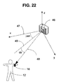
図22及び図23は、自動ビデオ記録システムの様々なコンポーネントの関係を示す概略図を示している。更に詳しくは、照準ベクトル48の向きは、カメラ46の元々の照準方向47からの角度における逸脱として表現されてもよい。カメラ46の場所に中心を有する地球固定座標系においては、向きの角度は、パン角とチルト角の合計として見なしてもよい。地球固定座標系を、カメラ46の初期方向47に沿ってx軸を有するものとして見なすことが便利である。パン角は、方向47及び49の間において座標系のxyプレーン内に位置している。チルト角は、xyプレーンに対して垂直であるプレーン内において、方向49と方向48の間である。
22 and 23 show schematic diagrams illustrating the relationship between the various components of the automatic video recording system. More specifically, the orientation of the aiming
基地局18は、位置決め指示を位置決め器に対して出力し、且つ、カメラ動作指示をカメラ46に対して出力する。位置決め器32は、リモート装置16に対して相対位置照準ベクトル48に沿って照準合わせするようにカメラ46を位置決めし、且つ、カメラ46のズームレベルは、カメラ46の視野が被写体12を上回るように設定されている。更には、カメラ46の焦点距離は、被写体12が合焦状態となるように制御される。最適なフレームサイズの選択肢は、一般に、使用される場所判定技術のなんらかの制限が付与された状態において、過剰に迅速なカメラの運動を伴うことなしに被写体12を視野内に維持しつつ、可能な限り詳細に示すべく可能な限りズームインするという所望の妥協の産物である。これらの制限には、限られた精度及び有限の応答速度が含まれる。
The
最適なフレームサイズの選択は、様々な方法によって実現されてもよい。ビデオを生成する好適な一実施形態においては、自動ビデオ記録システム10の既定の仕様は、人間のサイズよりも多少大きなフレームを記録するというものである。望ましいズームレベルのためのユーザー制御を提供することが有用である。例えば、大きな波が存在しているサーフィンセッションを記録するためには、ユーザーは、波の全体が視野に収まることを所望することになろう。別の好適な実施形態においては、迅速な運動を伴うスポーツの用途を記録するためには、人間の被写体12よりも格段に大きなフレームを記録することが有用である。このような用途においては、記録フレームが被写体との関係において小さ過ぎる場合には、被写体は、非常に迅速にフレームのエッジに到達することになる。カメラの向きは、被写体12を追跡するように調節され、且つ、視野が狭い場合には、快適な閲覧経験のために、カメラの向きを過剰に迅速に調節しなければならなくなるであろう。
The selection of the optimal frame size may be achieved by various methods. In one preferred embodiment for generating video, the default specification of the automatic
図23には、ズーム角の計算が概略的に示されている。カメラ46と被写体12の間の距離dは、場所判定技術によって判明することから、サイズhの視野について、カメラ46の視野60のラインの間のズーム角αが算出されることになる。例えば、h=40フィートであり、且つ、距離が、d=400フィートである場合には、ズーム角は、

又、場所判定技術の精度に疑義が生じた際には、或いは、場所判定技術信号が失われるか又は一時的に中断状態となった際には、ズームアウトすることも有利である。 It is also advantageous to zoom out when there is doubt about the accuracy of the location determination technique, or when the location determination technology signal is lost or temporarily interrupted.
図24は、本発明の好適な一実施形態によるズーム及び焦点制御を有する自動ビデオ記録システムを動作させる方法を示すフローチャートを示している。場所判定技術により、毎秒複数回にわたって定期的にリモート装置16の場所データを生成する。基地局18は、カメラ46の場所及び現在の向きに関するデータを保存する。基地局18とリモート装置16の間には、通信リンクが存在している。自動ビデオ記録システムの動作が継続している間に、リモート装置16(記録のターゲット)の場所の更新が予想される。自動ビデオ記録システム10の基地局18は、使用されている場所判定技術からのリモート装置16の更新済みの場所の受取りを待っている(ステップ500)。ステップ510において、更新済みの場所が受け取られた際に、ステップ520において、パン及びチルト照準角及びカメラ46とリモート装置16の間の距離の更新済みの値が判定される。好ましくは、不感帯が設定されており、これは、照準ベクトル48の向き及び/又は長さの変化が、特定の予め設定された限度外とならない限り、カメラ向き及びズームが変更されないことを意味している。ステップ530において、ステップ520の更新済みの角度及び距離が不感帯外にあるかどうかの判定が実行されている。新しい場所の座標が、被写体12が大きく動いたこと(即ち、不感帯の外部に動いたこと)を示している場合には、いくつかのイベントが発生することになる。ステップ540において、ターゲット照準角が算出されている。ターゲット照準角とは、場所判定技術から受け取った最新の情報に基づいてカメラ46を運動させるパン及びチルト角である。ターゲット照準角は、現在のカメラ向きの角度ではなく、むしろ、被写体12の現在の運動が変化を伴うことなしに継続した場合にカメラ46を回転させることになる角度である。ステップ550において、バックラッシュ補償により、ターゲット照準角を変更している。更なる詳細については、先程引用した第’203号特許出願明細書を参照されたい。ステップ560において、(パン及びチルト運動を生成するための)有効な駆動電圧を算出している。ステップ570において、有効電圧に基づいた指示を出力している。これらの電圧は、φによって表記されたパン及びチルト回転角とvによって表記されたパン及びチルト回転速度の両方を調節する。同時に、ステップ580において、被写体12の新しい位置についてズーム及び焦点を算出している。ステップ590において、新しいズーム角α及び新しい焦点距離dの指示を生成している。回転角及び回転速度の指示は、位置決め器32について出力され、ズーム及び焦点の指示は、カメラ46について出力される。図24のプロセスは、場所の更新がリモート装置16内において生成されるたびに、反復される。
FIG. 24 shows a flowchart illustrating a method of operating an automatic video recording system with zoom and focus control according to a preferred embodiment of the present invention. The location data of the
ステップ500の待機時間が過大である場合には、出力指示により、被写体12の最後の検出された位置に対してカメラ46を再方向付けすると共に再合焦させる。ここで、「過大な待機時間」は、例えば、2つの連続的な更新を逃すこととして定義されてもよい。この例を使用した場合には、「過大な待機時間」は、通常の更新周波数が約5Hzである場合には、約500ミリ秒となろう。基地局18は、場所判定技術からの更新を再度受け取る時点までズームアウトするように、カメラ46に対して指示するべくプログラムされてもよい。ステップ520において、リモート装置16の更新済みの場所座標が、カメラの角度における向きの観点において再算出され、且つ、ステップ530において、向きの変化がカメラの運動を正当化するかどうかを判定するべく、更新済みの向きと以前の向きの差が不感帯と比較される。一例として、角度の変化が約1度未満である場合には、カメラは運動しない。この機能は、不必要な小さな運動を防止する。例えば、被写体がスピードスケーターであり、且つ、リモート装置が彼の腕に装着されている場合には、左腕と右腕の交互の振りが、ほぼ毎秒ごとに発生することになろう。これらの腕の振りに追随するビデオを閲覧することは、非常に不愉快なものとなろう。被写体が不感帯外において運動している場合には、ステップ540において、ターゲットカメラの角度が算出されることになり、ステップ520において算出された角度は、ステップ540における計算用の1つの入力である。
If the waiting time in
設定された限度を超過する速度においては、カメラの運動が被写体12から大幅に遅延することになると予想され、且つ、最後の2つ又は3つ又はこれ以上の数の角度位置に基づいて、後続の位置を予測してもよい。これは、例えば、2つのデータ点からの線形補間を使用することにより、2つを上回る数の点からの最小二乗フィット線形補間を使用することにより、又は少なくとも3つの点に対する二次フィットを使用することにより、実行可能であり、この結果がターゲット角である。ステップ550において、ソフトウェアにより、バックラッシュについて補正した後に、ステップ560において、有効駆動電圧が演算される。このステップにおいては、比例−積分−微分法が適用されてもよい。好適な一実施形態においては、差が大きい場合に、カメラの運動の角速度も同様に大きくなるように、有効駆動電圧は、ターゲット角と現在のカメラの向きの間の差に比例している。
At speeds exceeding the set limits, the camera movement is expected to be significantly delayed from the subject 12, and the subsequent, based on the last two, three or more angular positions. May be predicted. This can be done, for example, by using linear interpolation from two data points, by using least squares fitting linear interpolation from more than two points, or by using a quadratic fit for at least three points. The result is the target angle. After correcting for backlash by software at
好適な一実施形態においては、場所の更新を受け取った後に、角度の変化が相対的に大きい場合には、駆動電圧は、相対的に高く(且つ、カメラの運動は、相対的に高速であり)、且つ、カメラの向きが既に遅延している場合には、更に高速になる。電圧は、V=K*(ターゲット角−カメラ角)として算出され、ここで、Kは、比例定数である。Vは、頻繁に更新され、例えば、ターゲット角は、場合によっては、約5Hzにおいて更新されてもよいが、Vは、約200Hzにおいて更新されてもよく、この更新の周波数は、基地局18がカメラ46の実際の角度位置に関する更新を位置決め器32から受け取る周波数によって左右される。自動ビデオ記録システム10の好適な実施形態においては、位置決め器32は、任意の所与の瞬間において実際の角度位置に関する情報を生成する1つ又は複数のエンコードホイールシステムを有する。
In a preferred embodiment, after receiving a location update, if the change in angle is relatively large, the drive voltage is relatively high (and the camera motion is relatively fast). ), And if the camera orientation is already delayed, the speed is further increased. The voltage is calculated as V = K * (target angle−camera angle), where K is a proportionality constant. V is frequently updated, for example, the target angle may be updated at about 5 Hz in some cases, but V may be updated at about 200 Hz, and the frequency of this update is determined by the
カメラ46がターゲット角に近づいた場合には、その運動は、オーバーシューティングを回避するために減速する。好適な一実施形態においては、被写体がその境界を過ぎて運動した際には、好ましくは、不感帯が再算出されている。好ましくは、不感帯は、以前の運動の方向における被写体12の中程度の運動さえもがカメラを運動させるが、逆方向における被写体12の類似の運動は、カメラを運動させないように、被写体よりも低速で運動するべきである。この方式により、不必要なカメラの運動(即ち、記録の不安定性)が大幅に低減される。
When the
比例−積分−微分制御の代替肢として、パルス幅変調が、単独で、又は電圧の調節との組合せにおいて、適用されてもよい。本発明の異なる実施形態においては、カメラ46を方向付けするべく位置決め器32内において使用されるモーターのタイプに応じて、その他の制御方式が利用されてもよい。例えば、ステップ又はマイクロステップ指示の間の時間インターバルを調節することにより、ステッパモーターの速度を制御してもよい。ステップの計数及び方向の追跡を維持することにより、エンコードホイールからなどのフィードバックに対する必要性を除去する開ループ制御を使用してもよい。
As an alternative to proportional-integral-derivative control, pulse width modulation may be applied alone or in combination with voltage regulation. In different embodiments of the present invention, other control schemes may be utilized, depending on the type of motor used in the
ステップ550において、駆動モーター及びギアボックスの既知の又は推定されたバックラッシュに基づいて、ターゲット角が変更されている。ステップ570において、モーター(例えば、パンドライブ)を調節する2つの指示パラメータが存在していることから、有効電圧及びターゲット角が位置決め器に対して出力されている。複数のドライブが使用されている実施形態においては、それぞれのドライブが、類似の処理の結果として得られる指示を受け取っている。
In
更には、ステップ590において、基地局18は、カメラ46と被写体12の間の距離に応じて、焦点及びズームと、従って、視野が、調節されるように、駆動信号を直接的にカメラに送信している。又、ズームも、被写体12の速度に応じて調節される。高速度においては、自動ビデオ記録システムは、カメラ46がズームアウトしない限り(即ち、フレームが拡大されない限り)、フレーム内に被写体を維持することができない場合がある。このようになる理由は、被写体12の運動との関係におけるカメラの位置決め運動の遅延に関係しており、且つ、不感帯にも起因している。不感帯の効果が割り引かれてもよい一定速度の状況においては、遅延は、主には、場所判定技術の時間遅延に起因している。遅延を生成しうるその他の要因には、場所判定技術の有限な更新周波数、基地局18内の電子装置の有限な処理速度、及びカメラ46の慣性との組合せにおける位置決め器32のモーターの限られたトルクが含まれる。例えば、上述の例の値を使用すれば、カメラのズーム角がα=5.7度であると仮定することにより、被写体12とカメラ46の間の距離は、400フィートであり、この結果、40フィートのフレーム幅が得られる。遅延時間が0.6秒であり、且つ、被写体12が40フィート/秒の速度で運動していると仮定すれば、0.6秒において、被写体12は、フレームの中心から約26フィートだけ移動することになり、これは、場所判定技術が被写体の場所を更新する前に、被写体がフレームの外に運動していることを意味している。この状況を回避するには、被写体12が画面から消える前に、即ち、被写体の速度が、例えば、20フィート/秒であり、且つ、加速している際には、ズームを調節しなければならない。遅延時間、速度、及び予測速度が大きいほど、被写体12の記録を維持するべく選択されるカメラ角αが大きくなる。
Furthermore, in
カメラの運動の遅延が大きい用途の場合には、過去の場所、速度、及び加速度情報に基づいてターゲットの予想位置を推定することにより、且つ、予想ターゲット角まで運動するように位置決め器に対して指示することにより、これを相殺してもよい。当業者には既知の方法を使用することにより、プロセスにより、最近の過去のs、v、及びα(場所、速度、及び加速度)値に基づいて被写体12の「次」の位置を予測する。カメラ46を位置決めする角速度は、被写体12の現在の位置と「次」の位置の間の角度の大きさに比例している。予測された「次」の位置を使用することにより、必要に応じて、相対的に高速のカメラの運動が可能となる。
For applications with large camera movement delays, the estimated position of the target is estimated based on past location, velocity, and acceleration information, and to the positioner to move to the expected target angle. This may be offset by instructing. By using methods known to those skilled in the art, the process predicts the “next” position of subject 12 based on the most recent past s, v, and α (location, velocity, and acceleration) values. The angular velocity for positioning the
基地局18によって使用されるプロセスは、遅延時間に起因して、且つ、場所判定技術の不確定性に起因して、発生可能な向きの誤差の大きさを推定又は予測する。基地局18は、視野が十分に広くなるようにズームを調節するべく、信号をカメラ46に送信するようにプログラムされている。実際には、遅延時間は、一秒程度であってもよい。好ましくは、カメラは、遅延時間における被写体12の運動が被写体を視野から外に移動させないように、ズームアウトするべきである。
The process used by the
ズーム調節の別の理由は、被写体の場所が、一時的に入手不能であるか、又は所定の期間にわたって失われているというものであってもよい。このような失われたデータ点は、様々な原因に起因するものであってもよい。例えば、全地球測位システムに基づいた場所判定技術の場合には、衛星−アンテナ間の通信における様々な短期的な問題に起因し、単一のデータ点が失われる場合がある。相対的に長い失われたデータシーケンスは、例えば、サーフィンの用途においては、被写体が水中に沈んでいることに起因するものであってもよい。又、基地局18とリモート装置16の間の無線通信が干渉によって中断される場合もある。基地局18によって使用されるプロセスは、好ましくは、単一の失われたデータ点を無視すると共にデータが複数のサイクルについて失われた際にはズームアウトするように、カメラ46に対して指示するべく設計されている。信号が再度出現した際に、被写体12は、被写体がある程度のかなりの距離を移動している場合にも、フレーム内に存在している確率が高くなる。
Another reason for zoom adjustment may be that the location of the subject is temporarily unavailable or has been lost for a predetermined period of time. Such lost data points may be due to various causes. For example, in the case of a location determination technique based on a global positioning system, a single data point may be lost due to various short-term problems in satellite-antenna communication. The relatively long lost data sequence may be due to the subject being submerged, for example, in surfing applications. Also, wireless communication between the
ズームアウトの要因が存在していない場合には、基地局18は、可能な限り高い分解能によって記録を生成するべく、ズームイン状態に戻るように、カメラ46に対して指示を送信する。
If there is no zoom-out factor, the
好適な一実施形態においては、自動ビデオ記録システム10は、複数のリモート装置16を追跡するべく、単一の位置決め器32と、単一のカメラ46と、を有している。例えば、スポーツイベントにおいて、複数の被写体12がカメラ46の視野内に存在する場合がある。基地局18は、複数の被写体12がカメラ46の視野内に出現することを保証するために、複数のリモート装置16の場所に基づいて、適切なズーム及び焦点との組合せにおいて、カメラの最適な方向を演算する。好適な一実施形態においては、可能な場合には、すべての被写体12をその視野内においてキャプチャするべく、且つ、すべての被写体の記録が可能でない場合には、記録のためにいくつかの被写体を選択するべく、カメラ46の方向付けと、そのズーム及び焦点の調節と、について、指示が送付される。好適な一実施形態においては、自動ビデオ記録システム10は、被写体が視野内に存在している又はカメラ46によって記録されていることを被写体が認知するように、記録されている複数の被写体に対してフィードバックを提供している。
In one preferred embodiment, the automated
複数の被写体12が単一のカメラ46によって記録されると共にすべての被写体12が同時に視野内に出現することができない実施形態においては、被写体の組の選択を実行しなければならない。選択される1つ又は複数の被写体は、複数の代替方法によって判定されてもよい。例えば、システムは、予め設定された最小ズームにおいて視野内においてキャプチャされうる被写体の数を極大化したり、或いは、システムは、予め設定された階層において被写体を追跡し、第1被写体が追跡されるが、更なる被写体が第1被写体の近傍にある際には、システムは、第1被写体と近傍の1つ又は複数の第2被写体をキャプチャするべく、カメラの向き及び/又はズームを調節する。
In embodiments where
別の好適な実施形態においては、カメラ46は、その向きを変更することなしに望ましい被写体の運動をキャプチャするのに十分な広い視野角を有する高分解能カメラである。既知であるカメラ46の場所及び向きと、場所判定技術を使用して判定された被写体12の場所と、により、システムは、フルビデオを、ちょうど被写体12を取り囲むと共に包含するエリアにトリミングし、カメラ46が被写体12を追いかけていた様子を高ズームレベルによってトリミング済みのビデオにおいて付与することができる。この実施形態の一例は、カメラの視野がゲレンデの大部分を包含するように、雪のスキーのゲレンデに対向した高分解能の固定カメラを利用している。リモート装置16を有するスキーヤーがカメラ46の視野内においてスキーをした際に、ソフトウェアは、フルビデオをデジタルトリミングし、スキーヤーが山をスキーで滑り降りるのに伴って、スキーヤーのズームインされた視野を含むビデオファイルを出力する。複数のスキーヤーが、それぞれ、その独自のリモート装置16を担持してもよく、且つ、システムは、別個に、それぞれの個々の被写体12の部分をトリミングして取り出すことができる。システムは、いずれのビデオセクションがいずれの特定のリモート装置16と関連付けられているかの情報を維持している。例えば、一日のスキーの終わりに、それぞれのユーザーは、その日にスキーしたユーザーのトリミングされたビデオを有するDVD又はその他の媒体ストレージ装置を収集してもよい。或いは、この代わりに、ビデオは、サーバーにアップロードされてもよく、このサーバー上において、それぞれのユーザーは、各自の特定のトリミングされたビデオファイルにアクセスしてもよい。本実施形態は、1つの広角ショットを記録し、且つ、視野内における被写体の場所に基づいて、そのショットのセクションをデジタルトリミングしていることから、この実施形態は、視野の異なる部分に同時に存在している複数のユーザーのトリミングされたビデオ記録を生成する能力を有する。リモート装置16を担持している複数のスキーヤーが、同時に、カメラ46の視野の異なる部分を通じてスキーをした場合には、システムは、それぞれのユーザーのビデオファイルを別個にトリミングし、且つ、トリミング済みのビデオファイルを保存する。本実施形態においては、ビデオのトリミングは、ポストリアルタイムで実行される。デジタルトリミングプロセスを遅延させることにより、ビデオのトリミングの前に、被写体12の経路全体が判明する。被写体の場所データのタイムスタンプとキャプチャされたビデオ上のタイムスタンプを同期化させることにより、且つ、データコレクション内の遅延時間を考慮することにより、カメラの視野内におけるターゲットの場所の正確な判定を決定可能であり、且つ、ビデオを適切にトリミングすることができる。
In another preferred embodiment, the
自動ビデオ記録システム10の好適な一実施形態においては、一意の無線チャネルが、同一のユーザーに属するリモート装置16と基地局18のペアによる双方向通信のために使用されている。別の好適な実施形態においては、複数の基地局18及びリモート装置16は、いずれもが、同一のチャネルを使用して通信しているが、一意の識別コードを利用して特定の基地局18を特定のリモート装置16とペア化している。このような実施形態においては、パケットの衝突回避プロセスを使用することにより、ペア化されたユニットが、同一エリア内において使用中であってもよいその他の基地局−リモート装置のペアを妨げたり又はそれらによって妨げられたりすることのない状態において、相互に容易に通信可能であることを保証してもよい。これは、通信を一意とするために使用され、且つ、同一の近傍領域内におけるいくつかの自動ビデオ記録システムの同時使用を許容する。
In a preferred embodiment of the automatic
以上の説明において、カメラという用語は、ビデオカメラ、写真カメラ、スマートフォン、ビデオキャプチャ装置などに言及すべく使用されていることに留意されたい。 It should be noted that in the above description, the term camera is used to refer to a video camera, a photo camera, a smartphone, a video capture device, and the like.
以上、本発明の様々な好適な実施形態、方法、用途、利点、及び特徴について説明したが、これらの具体的な実施形態、方法、用途、利点、及び特徴が本発明の実施を構成する唯一のものであると解釈してはならない。実際に、本発明の最も広範な範囲は、変更形態を含むことを理解されたい。更には、以上の説明及び添付の請求項から、当業者には、本出願人の発明の多くのその他の用途及び利点について明らかとなろう。 Although various preferred embodiments, methods, applications, advantages and features of the present invention have been described above, these specific embodiments, methods, applications, advantages and features constitute the only implementation of the present invention. Should not be interpreted as Indeed, it should be understood that the broadest scope of the invention includes modifications. Furthermore, from the foregoing description and the appended claims, many other uses and advantages of Applicant's invention will become apparent to those skilled in the art.
Claims (39)
基地局と、
前記自由運動する被写体と関連付けられたリモート装置と、
カメラを方向付けするための位置決め器と、
を有し、
前記基地局は、前記リモート装置と通信自在に結合され、且つ、前記リモート装置の場所に関する情報を受け取るように構成されており、且つ、前記基地局は、前記リモート装置とのやり取りに少なくとも部分的に基づいて前記カメラを方向付けするように前記位置決め器を制御することを特徴とするシステム。 In a system for automatic video recording of freely moving subjects,
A base station,
A remote device associated with the free-moving subject;
A positioner for orienting the camera;
Have
The base station is communicatively coupled to the remote device and configured to receive information regarding the location of the remote device, and the base station is at least partially in communication with the remote device. Controlling the positioner to orient the camera based on the system.
a)前記第1装置を支持するためのプラットフォームであって、
b)前記第1装置を前記プラットフォームに接続する際に前記第2装置の類似の向きに対して前記第1装置を視覚的に位置合わせするように構成されたプラットフォームと、
c)前記第1装置を前記プラットフォームに接続し、且つ、前記第2装置の向きと適応した状態において前記第1装置を保持するための第1留め具であって、
d)前記プラットフォームは、第2留め具により、前記第2装置に接続され、
e)前記プラットフォームは、前記第2留め具の軸を中心として回転してもよい、第1留め具と、
を有することを特徴とする装置。 A device for mounting the first device on the second device such that the first device and the second device remain aligned;
a) a platform for supporting the first device,
b) a platform configured to visually align the first device with respect to a similar orientation of the second device when connecting the first device to the platform;
c) a first fastener for connecting the first device to the platform and holding the first device in a state adapted to the orientation of the second device;
d) the platform is connected to the second device by a second fastener;
e) a first fastener that may rotate about the axis of the second fastener;
A device characterized by comprising:
内側表面と、外側表面と、を有する軟質ポリマーエンクロージャと、
電子的及び電気機械的コンポーネントと、
を有し、
前記内側表面は、前記電子的及び電気機械的コンポーネントと直接接触していることを特徴とする装置。 In waterproof electronic devices,
A soft polymer enclosure having an inner surface and an outer surface;
Electronic and electromechanical components;
Have
The apparatus wherein the inner surface is in direct contact with the electronic and electromechanical components.
前記被写体と関連付けられたリモート装置を有し、
前記リモート装置は、音声及び音響を検知するためのマイクロフォンを有し、前記リモート装置は、前記被写体を自動的に追跡するために使用されることを特徴とする装置。 In a device for automatic video recording of freely moving subjects,
A remote device associated with the subject;
The remote device includes a microphone for detecting sound and sound, and the remote device is used to automatically track the subject.
a)前記カメラ及び前記被写体の場所データを取得するステップと、
b)前記カメラと前記被写体の間の距離を判定するステップと、
c)前記カメラと前記被写体の間の前記距離に部分的に基づいて必要とされる視野を算出するステップと、
d)前記算出された必要とされる視野に基づいて前記カメラ用のズーム制御指示を提供するステップと、
を有することを特徴とする方法。 In a method of controlling a camera in automatic video recording of a subject by using a microcontroller with input and output control and connection,
a) obtaining location data of the camera and the subject;
b) determining a distance between the camera and the subject;
c) calculating a required field of view based in part on the distance between the camera and the subject;
d) providing a zoom control instruction for the camera based on the calculated required field of view;
A method characterized by comprising:
Applications Claiming Priority (13)
| Application Number | Priority Date | Filing Date | Title |
|---|---|---|---|
| US201261606358P | 2012-03-02 | 2012-03-02 | |
| US61/606,358 | 2012-03-02 | ||
| US201261606975P | 2012-03-05 | 2012-03-05 | |
| US201261606981P | 2012-03-05 | 2012-03-05 | |
| US201261606976P | 2012-03-05 | 2012-03-05 | |
| US61/606,976 | 2012-03-05 | ||
| US61/606,975 | 2012-03-05 | ||
| US61/606,981 | 2012-03-05 | ||
| US201261607549P | 2012-03-06 | 2012-03-06 | |
| US61/607,549 | 2012-03-06 | ||
| US201261745346P | 2012-12-21 | 2012-12-21 | |
| US61/745,346 | 2012-12-21 | ||
| PCT/US2013/028933 WO2013131100A1 (en) | 2012-03-02 | 2013-03-04 | Multifunction automatic video recording device |
Publications (2)
| Publication Number | Publication Date |
|---|---|
| JP2015513858A true JP2015513858A (en) | 2015-05-14 |
| JP2015513858A5 JP2015513858A5 (en) | 2016-05-12 |
Family
ID=49042894
Family Applications (1)
| Application Number | Title | Priority Date | Filing Date |
|---|---|---|---|
| JP2014560133A Pending JP2015513858A (en) | 2012-03-02 | 2013-03-04 | Multi-function automatic video recorder |
Country Status (6)
| Country | Link |
|---|---|
| US (1) | US9313394B2 (en) |
| EP (1) | EP2820840A4 (en) |
| JP (1) | JP2015513858A (en) |
| AU (1) | AU2013225635B2 (en) |
| CA (1) | CA2866131A1 (en) |
| WO (1) | WO2013131100A1 (en) |
Families Citing this family (29)
| Publication number | Priority date | Publication date | Assignee | Title |
|---|---|---|---|---|
| US8704904B2 (en) | 2011-12-23 | 2014-04-22 | H4 Engineering, Inc. | Portable system for high quality video recording |
| EP2618566A1 (en) * | 2012-01-23 | 2013-07-24 | FilmMe Group Oy | Controlling controllable device during performance |
| US10291725B2 (en) | 2012-11-21 | 2019-05-14 | H4 Engineering, Inc. | Automatic cameraman, automatic recording system and automatic recording network |
| WO2014182638A2 (en) | 2013-05-04 | 2014-11-13 | Christopher Decharms | Mobile security technology |
| CN105745915B (en) * | 2013-09-06 | 2019-02-15 | 索尼公司 | Image capturing device, methods and procedures |
| US20150288857A1 (en) * | 2014-04-07 | 2015-10-08 | Microsoft Corporation | Mount that facilitates positioning and orienting a mobile computing device |
| USD750693S1 (en) | 2014-07-03 | 2016-03-01 | H4 Engineering, Inc. | Electronic communication device with wearable housing |
| WO2016098458A1 (en) * | 2014-12-15 | 2016-06-23 | ソニー株式会社 | Information processing method, video processing device, and program |
| WO2016151925A1 (en) | 2015-03-26 | 2016-09-29 | 富士フイルム株式会社 | Tracking control device, tracking control method, tracking control program, and automatic tracking/image-capturing system |
| EP3317880A1 (en) | 2015-07-03 | 2018-05-09 | H4 Engineering, Inc. | Tracking camera network |
| US9992517B2 (en) | 2016-02-23 | 2018-06-05 | Comcast Cable Communications, Llc | Providing enhanced content based on user interactions |
| JP6685827B2 (en) * | 2016-05-09 | 2020-04-22 | キヤノン株式会社 | Image processing apparatus, image processing method and program |
| WO2017197174A1 (en) | 2016-05-11 | 2017-11-16 | H4 Engineering, Inc. | Apparatus and method for automatically orienting a camera at a target |
| US10564303B2 (en) * | 2016-07-26 | 2020-02-18 | International Business Machines Corporation | Parallel dipole line trap seismometer and vibration sensor |
| CN108297703A (en) * | 2017-01-11 | 2018-07-20 | 宁波轩悦行电动汽车服务有限公司 | Electric vehicle operational support method |
| WO2018164932A1 (en) * | 2017-03-08 | 2018-09-13 | Vid Scale, Inc. | Zoom coding using simultaneous and synchronous multiple-camera captures |
| US11394931B2 (en) * | 2017-03-13 | 2022-07-19 | Sony Group Corporation | Multimedia capture and editing using wireless sensors |
| WO2018177564A1 (en) * | 2017-03-30 | 2018-10-04 | Grau Paniello Sergi | Mounts for mobile devices |
| TWM560035U (en) * | 2017-11-13 | 2018-05-11 | 鄭宇傑 | Image tracking device |
| US10672243B2 (en) * | 2018-04-03 | 2020-06-02 | Chengfu Yu | Smart tracker IP camera device and method |
| US20190340768A1 (en) * | 2018-05-04 | 2019-11-07 | Tti (Macao Commercial Offshore) Limited | System and method of tracking an object |
| JP7146444B2 (en) * | 2018-05-11 | 2022-10-04 | キヤノン株式会社 | Control device, control method and program |
| CN109525752A (en) * | 2018-06-13 | 2019-03-26 | 幻想动力(上海)文化传播有限公司 | Capture apparatus and image pickup method |
| CN109688305A (en) * | 2018-08-27 | 2019-04-26 | 幻想动力(上海)文化传播有限公司 | Automatically snap control method, device and computer readable storage medium |
| CN109688306A (en) * | 2018-08-27 | 2019-04-26 | 幻想动力(上海)文化传播有限公司 | Automatically snap control method, device, system, equipment and computer readable storage medium |
| CN109547689A (en) * | 2018-08-27 | 2019-03-29 | 幻想动力(上海)文化传播有限公司 | Automatically snap control method, device and computer readable storage medium |
| US10939203B2 (en) * | 2019-06-28 | 2021-03-02 | International Business Machines Corporation | Forecasting sound in a live performance to determine microphone position |
| US11711616B2 (en) * | 2020-05-12 | 2023-07-25 | Electroapp, Llc | Portable system including motorized base controller and transmitter for tracking a moving target |
| CN113685682B (en) * | 2020-05-18 | 2023-02-21 | 北京小米移动软件有限公司 | Cloud platform |
Citations (5)
| Publication number | Priority date | Publication date | Assignee | Title |
|---|---|---|---|---|
| JP2002229672A (en) * | 2001-01-31 | 2002-08-16 | Hitachi Ltd | Portable information terminal |
| JP2005295222A (en) * | 2004-03-31 | 2005-10-20 | Casio Comput Co Ltd | Portable communication device |
| JP2008288151A (en) * | 2007-05-21 | 2008-11-27 | Casio Hitachi Mobile Communications Co Ltd | Waterproofing terminal structure |
| JP2010511111A (en) * | 2006-11-27 | 2010-04-08 | コンティネンタル オートモーティブ システムズ ユーエス, インコーポレイティッド | Reinforced key fob |
| JP2011124746A (en) * | 2009-12-10 | 2011-06-23 | Nec Casio Mobile Communications Ltd | Electronic device and program |
Family Cites Families (131)
| Publication number | Priority date | Publication date | Assignee | Title |
|---|---|---|---|---|
| US3469148A (en) * | 1967-11-08 | 1969-09-23 | Gen Motors Corp | Protectively covered hybrid microcircuits |
| US4041507A (en) * | 1975-07-02 | 1977-08-09 | W. Haking Industries, Ltd. | Camera for underwater and above water use |
| DE2650524B1 (en) * | 1976-11-04 | 1978-01-12 | Preussag Ag | Underwater camera |
| JPS53164140U (en) * | 1977-05-30 | 1978-12-22 | ||
| US4814711A (en) | 1984-04-05 | 1989-03-21 | Deseret Research, Inc. | Survey system and method for real time collection and processing of geophysicals data using signals from a global positioning satellite network |
| US4683729A (en) | 1985-06-24 | 1987-08-04 | Rogers Kermett A | Anti-theft apparatus for a riding saddle |
| US4980871A (en) | 1989-08-22 | 1990-12-25 | Visionary Products, Inc. | Ultrasonic tracking system |
| US5179421A (en) | 1990-08-20 | 1993-01-12 | Parkervision, Inc. | Remote tracking system particularly for moving picture cameras and method |
| US5572317A (en) * | 1990-05-31 | 1996-11-05 | Parkervision, Inc. | Remote-controlled tracking system for tracking a remote control unit and positioning and operating a camera and method |
| US5073824A (en) | 1990-06-15 | 1991-12-17 | Vertin Gregory D | Remote control and camera combination |
| JPH05509181A (en) | 1990-08-08 | 1993-12-16 | ディジタル アーツ フィルム アンド テレビジョン プロプライアトリー リミテッド | Motion control system for movie shooting |
| CA2081041C (en) | 1992-01-03 | 1996-08-06 | Robert Louis Beecher | Camera field of view indicator |
| US5363297A (en) | 1992-06-05 | 1994-11-08 | Larson Noble G | Automated camera-based tracking system for sports contests |
| GB9308952D0 (en) | 1993-04-30 | 1993-06-16 | Philips Electronics Uk Ltd | Tracking objects in video sequences |
| US5463432A (en) | 1993-05-24 | 1995-10-31 | Kahn; Philip | Miniature pan/tilt tracking mount |
| US5764786A (en) | 1993-06-10 | 1998-06-09 | Kuwashima; Shigesumi | Moving object measurement device employing a three-dimensional analysis to obtain characteristics of the moving object |
| FR2707159B1 (en) | 1993-07-09 | 1995-09-08 | Peaudouce | Disposable absorbent hygiene article. |
| US5438357A (en) | 1993-11-23 | 1995-08-01 | Mcnelley; Steve H. | Image manipulating teleconferencing system |
| EP0660131A1 (en) | 1993-12-23 | 1995-06-28 | Karl Osen | Camera guidance system |
| US5491632A (en) | 1994-05-26 | 1996-02-13 | General Motors Corporation | Rotary encoder with neutral position |
| US6002428A (en) | 1994-10-21 | 1999-12-14 | Sanyo Electric Co., Ltd. | Motion vector detection circuit and object tracking camera device utilizing the same |
| US5640007A (en) | 1995-06-21 | 1997-06-17 | Limitorque Corporation | Optical encoder comprising a plurality of encoder wheels |
| US5912980A (en) | 1995-07-13 | 1999-06-15 | Hunke; H. Martin | Target acquisition and tracking |
| JP4079463B2 (en) | 1996-01-26 | 2008-04-23 | ソニー株式会社 | Subject detection apparatus and subject detection method |
| US6173066B1 (en) | 1996-05-21 | 2001-01-09 | Cybernet Systems Corporation | Pose determination and tracking by matching 3D objects to a 2D sensor |
| US5878151A (en) | 1996-10-31 | 1999-03-02 | Combustion Engineering, Inc. | Moving object tracking |
| BR9805971A (en) | 1997-02-06 | 1999-08-31 | Koninkl Philips Electronics Nv | Process and system for object segmentation and tracking |
| US5973732A (en) | 1997-02-19 | 1999-10-26 | Guthrie; Thomas C. | Object tracking system for monitoring a controlled space |
| GB2324428A (en) | 1997-04-17 | 1998-10-21 | Sharp Kk | Image tracking; observer tracking stereoscopic display |
| US6355881B1 (en) * | 1997-05-05 | 2002-03-12 | Brant P. Braeges | Means for sealing an electronic or optical component within an enclosure housing |
| US6188777B1 (en) | 1997-08-01 | 2001-02-13 | Interval Research Corporation | Method and apparatus for personnel detection and tracking |
| JP3481430B2 (en) | 1997-09-11 | 2003-12-22 | 富士通株式会社 | Mobile tracking device |
| KR100295201B1 (en) * | 1998-05-25 | 2001-09-17 | 이정훈 | Location tracking relay broadcasting system |
| US6603408B1 (en) * | 1998-06-01 | 2003-08-05 | Brenda Lewellen Gaba | Flexible membrane keyboard |
| US6690978B1 (en) | 1998-07-08 | 2004-02-10 | Jerry Kirsch | GPS signal driven sensor positioning system |
| US7920163B1 (en) * | 1999-06-15 | 2011-04-05 | Tessera International, Inc. | Sealed, waterproof digital electronic camera system and method of fabricating same |
| US6795110B1 (en) * | 1999-06-15 | 2004-09-21 | Philip Kossin | Weatherproof and watertight digital electronic camera, including a solid or fluid-filled digital camera operating at great depths |
| US6172640B1 (en) | 1999-06-18 | 2001-01-09 | Jennifer Durst | Pet locator |
| TW519826B (en) | 1999-11-29 | 2003-02-01 | Koninkl Philips Electronics Nv | Personality-based intelligent camera system |
| US6596976B2 (en) | 1999-12-07 | 2003-07-22 | American Gnc Corporation | Method and system for pointing and stabilizing a device |
| US6909381B2 (en) | 2000-02-12 | 2005-06-21 | Leonard Richard Kahn | Aircraft collision avoidance system |
| AU2001247302A1 (en) | 2000-03-10 | 2001-09-24 | Sensormatic Electronics Corporation | Method and apparatus for object surveillance with a movable camera |
| GB2360972A (en) | 2000-04-05 | 2001-10-10 | Nokia Mobile Phones Ltd | Portable electronic apparatus with a moulded cover |
| US20020005902A1 (en) | 2000-06-02 | 2002-01-17 | Yuen Henry C. | Automatic video recording system using wide-and narrow-field cameras |
| US7006950B1 (en) | 2000-06-12 | 2006-02-28 | Siemens Corporate Research, Inc. | Statistical modeling and performance characterization of a real-time dual camera surveillance system |
| DE60143357D1 (en) | 2000-06-23 | 2010-12-09 | Sportvision Inc | GPS-BASED TRACKING SYSTEM |
| EP1168830A1 (en) | 2000-06-30 | 2002-01-02 | Wells & Verne Investments Ltd | Computer aided image capturing system |
| US6519860B1 (en) | 2000-10-19 | 2003-02-18 | Sandia Corporation | Position feedback control system |
| JP4107810B2 (en) * | 2001-03-21 | 2008-06-25 | 株式会社リコー | Waterproof case for mobile devices |
| GB2373943A (en) | 2001-03-28 | 2002-10-02 | Hewlett Packard Co | Visible and infrared imaging camera |
| GB2373942A (en) | 2001-03-28 | 2002-10-02 | Hewlett Packard Co | Camera records images only when a tag is present |
| US20030169339A1 (en) * | 2001-10-01 | 2003-09-11 | Digeo. Inc. | System and method for tracking an object during video communication |
| JP4147054B2 (en) | 2002-05-17 | 2008-09-10 | オリンパス株式会社 | Stereoscopic observation device |
| US6751409B2 (en) * | 2002-05-31 | 2004-06-15 | Fuji Photo Film Co., Ltd. | Exterior case of electronic appliance |
| US20040006424A1 (en) | 2002-06-28 | 2004-01-08 | Joyce Glenn J. | Control system for tracking and targeting multiple autonomous objects |
| US6972787B1 (en) | 2002-06-28 | 2005-12-06 | Digeo, Inc. | System and method for tracking an object with multiple cameras |
| US7349008B2 (en) | 2002-11-30 | 2008-03-25 | Microsoft Corporation | Automated camera management system and method for capturing presentations using videography rules |
| KR100507780B1 (en) | 2002-12-20 | 2005-08-17 | 한국전자통신연구원 | Apparatus and method for high-speed marker-free motion capture |
| US6952646B2 (en) | 2003-05-14 | 2005-10-04 | Chang Industry, Inc. | Tracking device and associated system and method |
| JP2005020205A (en) | 2003-06-24 | 2005-01-20 | Casio Comput Co Ltd | Picture photographing device |
| CA2445814A1 (en) | 2003-10-20 | 2005-04-20 | Colin Wishart | Automated audio/video recording system |
| WO2005039394A2 (en) | 2003-10-23 | 2005-05-06 | Tsx Products Corporation | An apparatus for automatically pointing a device at a target |
| US7081822B2 (en) | 2003-12-18 | 2006-07-25 | Se-Kure Controls, Inc. | Sensing assembly for article to be monitored |
| JP4385768B2 (en) | 2004-01-09 | 2009-12-16 | 株式会社デンソー | Motor control device |
| JP4414773B2 (en) * | 2004-01-15 | 2010-02-10 | オリンパス株式会社 | Waterproof drop structure for sound generation or sound collection member and electronic device having the same |
| JP4478510B2 (en) | 2004-06-03 | 2010-06-09 | キヤノン株式会社 | Camera system, camera, and camera control method |
| US7060921B2 (en) * | 2004-08-25 | 2006-06-13 | Sony Corporation | Water-resistant case for electronic devices |
| US7204107B2 (en) | 2004-08-26 | 2007-04-17 | Se-Kure Controls, Inc. | Adjustable tethering system for securing an article |
| US20080105527A1 (en) | 2004-09-16 | 2008-05-08 | Steven Andrew Leftly | Switches and Devices for Integrated Soft Component Systems |
| US7426338B2 (en) * | 2004-11-29 | 2008-09-16 | Olympus Imaging Corp. | Switch mechanism usable underwater |
| JP4413771B2 (en) * | 2004-12-28 | 2010-02-10 | Hoya株式会社 | Camera with waterproof function |
| JP2006243074A (en) * | 2005-02-28 | 2006-09-14 | Olympus Imaging Corp | Water-proof housing |
| ES2790885T3 (en) | 2005-03-29 | 2020-10-29 | Sportvu Ltd | Real-time object tracking and motion capture at sporting events |
| US7239975B2 (en) | 2005-04-02 | 2007-07-03 | American Gnc Corporation | Method and system for automatic stabilization and pointing control of a device |
| US20080002031A1 (en) | 2005-05-06 | 2008-01-03 | John-Paul P. Cana | Multi-axis control of a fixed or moving device based on a wireless tracking location of one or many target devices |
| GB0510312D0 (en) | 2005-05-20 | 2005-06-29 | Wearable Technologies Ltd | Garment |
| US7672781B2 (en) | 2005-06-04 | 2010-03-02 | Microstrain, Inc. | Miniaturized wireless inertial sensing system |
| CN101222957B (en) | 2005-07-14 | 2012-01-11 | 查尔斯·D·休斯顿 | GPS based spectator and participant sport system and method |
| US8471812B2 (en) | 2005-09-23 | 2013-06-25 | Jesse C. Bunch | Pointing and identification device |
| US7728264B2 (en) | 2005-10-05 | 2010-06-01 | Raytheon Company | Precision targeting |
| WO2007059301A2 (en) | 2005-11-16 | 2007-05-24 | Integrated Equine Technologies Llc | Automated video system for context-appropriate object tracking |
| US7450835B2 (en) | 2005-12-14 | 2008-11-11 | Lackey Robert C | Tripod device for mounting a camera and tracking movable objects |
| US7508352B2 (en) | 2006-01-18 | 2009-03-24 | Motorola, Inc. | Embedded assembly including moveable element and antenna element |
| JP4241742B2 (en) * | 2006-01-31 | 2009-03-18 | パナソニック株式会社 | Automatic tracking device and automatic tracking method |
| KR101001060B1 (en) | 2006-03-15 | 2010-12-14 | 오므론 가부시키가이샤 | Tracking device, tracking method, tracking device control program, and comuter readable recording medium |
| WO2007115097A2 (en) | 2006-03-31 | 2007-10-11 | Checkpoint Systems, Inc. | System and method for securing and displaying items for merchandising |
| CN101427155B (en) | 2006-04-21 | 2011-09-28 | 法罗技术股份有限公司 | Camera based six degree-of-freedom target measuring and target tracking device with rotatable mirror |
| US20070292118A1 (en) * | 2006-06-14 | 2007-12-20 | Sony Ericsson Mobile Communications Ab | Underwater image capture |
| KR101186608B1 (en) * | 2006-07-14 | 2012-09-27 | 엘지전자 주식회사 | Mobile communication device |
| US7843322B2 (en) | 2006-08-14 | 2010-11-30 | Honeywell International Inc. | Instant messaging applications in security systems |
| DE112007001950T5 (en) | 2006-08-21 | 2009-07-02 | Innotec Corporation, Zeeland | Electrical device with platinum-free mounting arrangement for electrical components |
| US7578357B2 (en) | 2006-09-12 | 2009-08-25 | Black & Decker Inc. | Driver with external torque value indicator integrated with spindle lock and related method |
| JP2008227877A (en) | 2007-03-13 | 2008-09-25 | Hitachi Ltd | Video information processor |
| US7712933B2 (en) | 2007-03-19 | 2010-05-11 | Interlum, Llc | Light for vehicles |
| US8408773B2 (en) * | 2007-03-19 | 2013-04-02 | Innotec Corporation | Light for vehicles |
| US7730852B2 (en) | 2007-05-18 | 2010-06-08 | Kramer Robert H | Portable animal restraint and feeding station |
| US8264584B2 (en) | 2007-05-31 | 2012-09-11 | Panasonic Corporation | Image capturing apparatus, additional information providing server, and additional information filtering system |
| US7933122B2 (en) * | 2007-06-06 | 2011-04-26 | Otter Products, Llc | Protective enclosure for a computer |
| WO2009076579A2 (en) | 2007-12-12 | 2009-06-18 | Innotec Corporation | Overmolded circuit board and method |
| TWI369135B (en) | 2007-12-31 | 2012-07-21 | Nat Applied Res Lab Nat Ct For High Performance Computing | Camera control system capable of positioning and tracking object in space and method thereof |
| US20090206077A1 (en) * | 2008-02-19 | 2009-08-20 | Daymen Photo Marketing Lp, A Canadian Limited Partnership | Protective Camera Enclosure |
| US7547875B1 (en) | 2008-05-29 | 2009-06-16 | Delta Electronics, Inc. | Absolute type encoder apparatus and method for operating the same |
| US20090300101A1 (en) | 2008-05-30 | 2009-12-03 | Carl Johan Freer | Augmented reality platform and method using letters, numbers, and/or math symbols recognition |
| ES2400310T3 (en) | 2008-06-18 | 2013-04-09 | Saab Ab | Verification of the validity of the position information of a vehicle |
| FR2933511A1 (en) | 2008-07-04 | 2010-01-08 | Optinnova | INTERACTIVE VISUALIZATION DEVICE AND METHOD USING DETECTION CAMERA AND OPTICAL POINTER |
| US9185361B2 (en) | 2008-07-29 | 2015-11-10 | Gerald Curry | Camera-based tracking and position determination for sporting events using event information and intelligence data extracted in real-time from position information |
| US8760520B2 (en) | 2008-11-10 | 2014-06-24 | Eduard Levin | System and method for tracking and monitoring personnel and equipment |
| US9141860B2 (en) | 2008-11-17 | 2015-09-22 | Liveclips Llc | Method and system for segmenting and transmitting on-demand live-action video in real-time |
| US8274544B2 (en) | 2009-03-23 | 2012-09-25 | Eastman Kodak Company | Automated videography systems |
| US8237771B2 (en) | 2009-03-26 | 2012-08-07 | Eastman Kodak Company | Automated videography based communications |
| US20100298025A1 (en) * | 2009-05-19 | 2010-11-25 | Cezar Spence | Waterproof cell phone |
| US8374495B2 (en) * | 2009-06-04 | 2013-02-12 | Sanwa Technologies Limited | User-configurable waterproof camera case |
| US8253792B2 (en) | 2009-08-28 | 2012-08-28 | GM Global Technology Operations LLC | Vision system for monitoring humans in dynamic environments |
| KR101048856B1 (en) | 2009-09-04 | 2011-07-13 | 주식회사 에스원 | Image Intrusion Detection System and Method Using Dot Lighting |
| JP5514506B2 (en) | 2009-10-21 | 2014-06-04 | 株式会社日立国際電気 | Intruder monitoring system and intruder monitoring method |
| US9602776B2 (en) | 2010-02-02 | 2017-03-21 | Verizon Patent And Licensing Inc. | Accessing web-based cameras arranged by category |
| WO2011100480A1 (en) | 2010-02-10 | 2011-08-18 | Brian Lamb | Automatic motion tracking, event detection and video image capture and tagging |
| US8953117B2 (en) * | 2010-03-19 | 2015-02-10 | Balboa Water Group, Inc. | Vented waterproof touch screen panel |
| US8294843B2 (en) * | 2010-03-19 | 2012-10-23 | Balboa Instruments, Inc. | Waterproof touch screen panel with protective film |
| US8525340B2 (en) * | 2010-06-11 | 2013-09-03 | Premitec, Inc. | Flexible electronic devices and related methods |
| USD640679S1 (en) * | 2010-10-22 | 2011-06-28 | Otter Products, Llc | Cover for an electronic device |
| TWI448803B (en) * | 2010-12-31 | 2014-08-11 | Altek Corp | Water-proofing image-capturing apparatus |
| US20120262618A1 (en) * | 2011-04-14 | 2012-10-18 | Amphibian Labs Llc | Waterproof case for hand held computing device |
| US8995713B2 (en) | 2011-04-25 | 2015-03-31 | Fujitsu Limited | Motion tracking using identifying feature requiring line of sight of camera |
| US8944614B2 (en) * | 2011-04-29 | 2015-02-03 | xDEV, INC. | Protective cover for an electronic device |
| US9025948B2 (en) * | 2011-06-20 | 2015-05-05 | A.G. Findings & Mfg. Co., Inc. | Camera protection module for portable device case |
| TW201303469A (en) * | 2011-07-14 | 2013-01-16 | Altek Corp | Water-proofing camera |
| US8750674B2 (en) | 2011-09-26 | 2014-06-10 | Intellectual Ventures Fund 83 Llc | Remotely controllable digital video camera system |
| US20130278845A1 (en) | 2012-04-18 | 2013-10-24 | Kent Displays Incorporated | Embedded electrooptical display |
| WO2013181644A1 (en) * | 2012-06-01 | 2013-12-05 | Treefrog Developments, Inc. | Housing for an electronic device with camera, microphone and flash isolation |
| US20140226062A1 (en) * | 2013-02-11 | 2014-08-14 | Matthew B. Parrill | Protective cover for an electronic device |
-
2013
- 2013-03-04 WO PCT/US2013/028933 patent/WO2013131100A1/en active Application Filing
- 2013-03-04 US US13/784,536 patent/US9313394B2/en active Active
- 2013-03-04 EP EP13754983.8A patent/EP2820840A4/en not_active Withdrawn
- 2013-03-04 CA CA2866131A patent/CA2866131A1/en not_active Abandoned
- 2013-03-04 JP JP2014560133A patent/JP2015513858A/en active Pending
- 2013-03-04 AU AU2013225635A patent/AU2013225635B2/en not_active Ceased
Patent Citations (5)
| Publication number | Priority date | Publication date | Assignee | Title |
|---|---|---|---|---|
| JP2002229672A (en) * | 2001-01-31 | 2002-08-16 | Hitachi Ltd | Portable information terminal |
| JP2005295222A (en) * | 2004-03-31 | 2005-10-20 | Casio Comput Co Ltd | Portable communication device |
| JP2010511111A (en) * | 2006-11-27 | 2010-04-08 | コンティネンタル オートモーティブ システムズ ユーエス, インコーポレイティッド | Reinforced key fob |
| JP2008288151A (en) * | 2007-05-21 | 2008-11-27 | Casio Hitachi Mobile Communications Co Ltd | Waterproofing terminal structure |
| JP2011124746A (en) * | 2009-12-10 | 2011-06-23 | Nec Casio Mobile Communications Ltd | Electronic device and program |
Also Published As
| Publication number | Publication date |
|---|---|
| AU2013225635B2 (en) | 2017-10-26 |
| EP2820840A1 (en) | 2015-01-07 |
| WO2013131100A1 (en) | 2013-09-06 |
| CA2866131A1 (en) | 2013-06-09 |
| US20130230293A1 (en) | 2013-09-05 |
| AU2013225635A1 (en) | 2014-10-23 |
| US9313394B2 (en) | 2016-04-12 |
| EP2820840A4 (en) | 2015-12-30 |
Similar Documents
| Publication | Publication Date | Title |
|---|---|---|
| US9313394B2 (en) | Waterproof electronic device | |
| JP6227553B2 (en) | Portable system for high quality automatic recording | |
| US9723192B1 (en) | Application dependent video recording device architecture | |
| US11831983B2 (en) | Portable digital video camera configured for remote image acquisition control and viewing | |
| US9684056B2 (en) | Automatic object tracking camera | |
| AU2013225712B2 (en) | Apparatus and method for automatic video recording | |
| US10048755B2 (en) | Systems and methods for converting sensory data to haptic effects | |
| US20150036047A1 (en) | Orientation control of an image sensor of a portable digital video camera | |
| US20190313020A1 (en) | Mobile Tracking Camera Device | |
| EP2826239A1 (en) | System and method for video recording and webcasting sporting events | |
| US20230388640A1 (en) | Portable system including motorized base controller and transmitter for tracking a moving target | |
| EP3422693A1 (en) | Application dependent video recording device architecture | |
| JP2005277845A (en) | Photographing controller | |
| WO2020095647A1 (en) | Image processing device, image processing server, image processing method, computer program, and storage medium | |
| JP2022122720A (en) | Platform control device and camera | |
| TWM459641U (en) | Automatic target tracking system | |
| JPH05103247A (en) | Unmanned photographing device |
Legal Events
| Date | Code | Title | Description |
|---|---|---|---|
| A521 | Request for written amendment filed |
Free format text: JAPANESE INTERMEDIATE CODE: A523 Effective date: 20160302 |
|
| A621 | Written request for application examination |
Free format text: JAPANESE INTERMEDIATE CODE: A621 Effective date: 20160302 |
|
| A521 | Request for written amendment filed |
Free format text: JAPANESE INTERMEDIATE CODE: A523 Effective date: 20160311 |
|
| A977 | Report on retrieval |
Free format text: JAPANESE INTERMEDIATE CODE: A971007 Effective date: 20170321 |
|
| A131 | Notification of reasons for refusal |
Free format text: JAPANESE INTERMEDIATE CODE: A131 Effective date: 20170328 |
|
| A02 | Decision of refusal |
Free format text: JAPANESE INTERMEDIATE CODE: A02 Effective date: 20171031 |