JP2015512358A - Shock absorbing protective structure with internal reinforcement and its material - Google Patents
Shock absorbing protective structure with internal reinforcement and its material Download PDFInfo
- Publication number
- JP2015512358A JP2015512358A JP2015501860A JP2015501860A JP2015512358A JP 2015512358 A JP2015512358 A JP 2015512358A JP 2015501860 A JP2015501860 A JP 2015501860A JP 2015501860 A JP2015501860 A JP 2015501860A JP 2015512358 A JP2015512358 A JP 2015512358A
- Authority
- JP
- Japan
- Prior art keywords
- layer
- pad
- case
- foam
- hinge
- Prior art date
- Legal status (The legal status is an assumption and is not a legal conclusion. Google has not performed a legal analysis and makes no representation as to the accuracy of the status listed.)
- Pending
Links
- 239000000463 material Substances 0.000 title claims description 65
- 230000001681 protective effect Effects 0.000 title abstract description 23
- 230000002787 reinforcement Effects 0.000 title description 7
- 230000035939 shock Effects 0.000 title description 7
- 230000003014 reinforcing effect Effects 0.000 claims abstract description 23
- 239000006260 foam Substances 0.000 claims description 38
- 239000004744 fabric Substances 0.000 claims description 31
- 230000004888 barrier function Effects 0.000 claims description 13
- 239000004745 nonwoven fabric Substances 0.000 claims description 6
- 239000010410 layer Substances 0.000 description 136
- 239000000853 adhesive Substances 0.000 description 7
- 230000001070 adhesive effect Effects 0.000 description 7
- 230000008901 benefit Effects 0.000 description 7
- 238000004519 manufacturing process Methods 0.000 description 7
- 238000005452 bending Methods 0.000 description 6
- 230000006835 compression Effects 0.000 description 6
- 238000007906 compression Methods 0.000 description 6
- 230000006378 damage Effects 0.000 description 6
- 210000001513 elbow Anatomy 0.000 description 6
- 125000006850 spacer group Chemical group 0.000 description 6
- 239000000126 substance Substances 0.000 description 6
- 230000000694 effects Effects 0.000 description 5
- 238000000034 method Methods 0.000 description 5
- 238000010521 absorption reaction Methods 0.000 description 4
- 239000013543 active substance Substances 0.000 description 4
- 239000012790 adhesive layer Substances 0.000 description 4
- 208000014674 injury Diseases 0.000 description 4
- 230000002093 peripheral effect Effects 0.000 description 4
- 230000002829 reductive effect Effects 0.000 description 4
- 239000011347 resin Substances 0.000 description 4
- 229920005989 resin Polymers 0.000 description 4
- 230000000844 anti-bacterial effect Effects 0.000 description 3
- 230000015572 biosynthetic process Effects 0.000 description 3
- 239000012530 fluid Substances 0.000 description 3
- 210000000497 foam cell Anatomy 0.000 description 3
- 238000003780 insertion Methods 0.000 description 3
- 230000037431 insertion Effects 0.000 description 3
- 210000001503 joint Anatomy 0.000 description 3
- 238000009940 knitting Methods 0.000 description 3
- 239000004033 plastic Substances 0.000 description 3
- 229920003023 plastic Polymers 0.000 description 3
- 229920000728 polyester Polymers 0.000 description 3
- 229910052709 silver Inorganic materials 0.000 description 3
- 239000004332 silver Substances 0.000 description 3
- 229920002725 thermoplastic elastomer Polymers 0.000 description 3
- 230000008733 trauma Effects 0.000 description 3
- 239000002759 woven fabric Substances 0.000 description 3
- RYGMFSIKBFXOCR-UHFFFAOYSA-N Copper Chemical compound [Cu] RYGMFSIKBFXOCR-UHFFFAOYSA-N 0.000 description 2
- 229920002334 Spandex Polymers 0.000 description 2
- 238000005299 abrasion Methods 0.000 description 2
- 239000002313 adhesive film Substances 0.000 description 2
- 210000003423 ankle Anatomy 0.000 description 2
- 230000008859 change Effects 0.000 description 2
- 229910052802 copper Inorganic materials 0.000 description 2
- 239000010949 copper Substances 0.000 description 2
- 238000013461 design Methods 0.000 description 2
- 239000011521 glass Substances 0.000 description 2
- 210000003127 knee Anatomy 0.000 description 2
- 238000012986 modification Methods 0.000 description 2
- 230000004048 modification Effects 0.000 description 2
- 230000036961 partial effect Effects 0.000 description 2
- 239000011148 porous material Substances 0.000 description 2
- 230000008569 process Effects 0.000 description 2
- 210000002832 shoulder Anatomy 0.000 description 2
- 239000004759 spandex Substances 0.000 description 2
- OKTJSMMVPCPJKN-UHFFFAOYSA-N Carbon Chemical compound [C] OKTJSMMVPCPJKN-UHFFFAOYSA-N 0.000 description 1
- 229920000544 Gore-Tex Polymers 0.000 description 1
- 229920000271 Kevlar® Polymers 0.000 description 1
- 239000004721 Polyphenylene oxide Substances 0.000 description 1
- 239000004433 Thermoplastic polyurethane Substances 0.000 description 1
- 208000027418 Wounds and injury Diseases 0.000 description 1
- 239000012190 activator Substances 0.000 description 1
- 239000003242 anti bacterial agent Substances 0.000 description 1
- 230000000843 anti-fungal effect Effects 0.000 description 1
- 229940121375 antifungal agent Drugs 0.000 description 1
- 239000003429 antifungal agent Substances 0.000 description 1
- 238000013459 approach Methods 0.000 description 1
- 230000000386 athletic effect Effects 0.000 description 1
- 229910052799 carbon Inorganic materials 0.000 description 1
- 125000002915 carbonyl group Chemical group [*:2]C([*:1])=O 0.000 description 1
- 210000004027 cell Anatomy 0.000 description 1
- 230000001413 cellular effect Effects 0.000 description 1
- 239000003086 colorant Substances 0.000 description 1
- 150000001875 compounds Chemical class 0.000 description 1
- 230000001010 compromised effect Effects 0.000 description 1
- 238000005336 cracking Methods 0.000 description 1
- 229920003020 cross-linked polyethylene Polymers 0.000 description 1
- 239000004703 cross-linked polyethylene Substances 0.000 description 1
- 230000032798 delamination Effects 0.000 description 1
- 238000003795 desorption Methods 0.000 description 1
- 239000003599 detergent Substances 0.000 description 1
- 239000000428 dust Substances 0.000 description 1
- 229920001971 elastomer Polymers 0.000 description 1
- 239000000806 elastomer Substances 0.000 description 1
- 210000002310 elbow joint Anatomy 0.000 description 1
- 238000004146 energy storage Methods 0.000 description 1
- 238000001704 evaporation Methods 0.000 description 1
- 230000008020 evaporation Effects 0.000 description 1
- 239000000835 fiber Substances 0.000 description 1
- 238000007667 floating Methods 0.000 description 1
- 239000006261 foam material Substances 0.000 description 1
- 210000001624 hip Anatomy 0.000 description 1
- 125000004435 hydrogen atom Chemical group [H]* 0.000 description 1
- 238000010348 incorporation Methods 0.000 description 1
- 238000009413 insulation Methods 0.000 description 1
- 230000010354 integration Effects 0.000 description 1
- 239000004761 kevlar Substances 0.000 description 1
- 230000000670 limiting effect Effects 0.000 description 1
- 238000005259 measurement Methods 0.000 description 1
- 229910052751 metal Inorganic materials 0.000 description 1
- 239000002184 metal Substances 0.000 description 1
- 239000003607 modifier Substances 0.000 description 1
- 239000013518 molded foam Substances 0.000 description 1
- 238000000465 moulding Methods 0.000 description 1
- 239000002245 particle Substances 0.000 description 1
- 230000035699 permeability Effects 0.000 description 1
- 229920000570 polyether Polymers 0.000 description 1
- 239000002861 polymer material Substances 0.000 description 1
- 229920001296 polysiloxane Polymers 0.000 description 1
- 229920006264 polyurethane film Polymers 0.000 description 1
- 230000002265 prevention Effects 0.000 description 1
- 239000011241 protective layer Substances 0.000 description 1
- 230000001012 protector Effects 0.000 description 1
- 239000011435 rock Substances 0.000 description 1
- 229920006395 saturated elastomer Polymers 0.000 description 1
- 238000000926 separation method Methods 0.000 description 1
- 239000007779 soft material Substances 0.000 description 1
- 239000007787 solid Substances 0.000 description 1
- 230000003068 static effect Effects 0.000 description 1
- 125000001424 substituent group Chemical group 0.000 description 1
- 239000002344 surface layer Substances 0.000 description 1
- 210000004243 sweat Anatomy 0.000 description 1
- 238000003856 thermoforming Methods 0.000 description 1
- 229920001169 thermoplastic Polymers 0.000 description 1
- 229920002803 thermoplastic polyurethane Polymers 0.000 description 1
- 239000004416 thermosoftening plastic Substances 0.000 description 1
- 239000013585 weight reducing agent Substances 0.000 description 1
Images


Classifications
-
- A—HUMAN NECESSITIES
- A41—WEARING APPAREL
- A41D—OUTERWEAR; PROTECTIVE GARMENTS; ACCESSORIES
- A41D13/00—Professional, industrial or sporting protective garments, e.g. surgeons' gowns or garments protecting against blows or punches
- A41D13/0015—Sports garments other than provided for in groups A41D13/0007 - A41D13/088
-
- A—HUMAN NECESSITIES
- A41—WEARING APPAREL
- A41D—OUTERWEAR; PROTECTIVE GARMENTS; ACCESSORIES
- A41D13/00—Professional, industrial or sporting protective garments, e.g. surgeons' gowns or garments protecting against blows or punches
- A41D13/05—Professional, industrial or sporting protective garments, e.g. surgeons' gowns or garments protecting against blows or punches protecting only a particular body part
-
- A—HUMAN NECESSITIES
- A45—HAND OR TRAVELLING ARTICLES
- A45C—PURSES; LUGGAGE; HAND CARRIED BAGS
- A45C11/00—Receptacles for purposes not provided for in groups A45C1/00-A45C9/00
-
- A—HUMAN NECESSITIES
- A63—SPORTS; GAMES; AMUSEMENTS
- A63B—APPARATUS FOR PHYSICAL TRAINING, GYMNASTICS, SWIMMING, CLIMBING, OR FENCING; BALL GAMES; TRAINING EQUIPMENT
- A63B71/00—Games or sports accessories not covered in groups A63B1/00 - A63B69/00
- A63B71/08—Body-protectors for players or sportsmen, i.e. body-protecting accessories affording protection of body parts against blows or collisions
-
- B—PERFORMING OPERATIONS; TRANSPORTING
- B32—LAYERED PRODUCTS
- B32B—LAYERED PRODUCTS, i.e. PRODUCTS BUILT-UP OF STRATA OF FLAT OR NON-FLAT, e.g. CELLULAR OR HONEYCOMB, FORM
- B32B15/00—Layered products comprising a layer of metal
- B32B15/02—Layer formed of wires, e.g. mesh
-
- B—PERFORMING OPERATIONS; TRANSPORTING
- B32—LAYERED PRODUCTS
- B32B—LAYERED PRODUCTS, i.e. PRODUCTS BUILT-UP OF STRATA OF FLAT OR NON-FLAT, e.g. CELLULAR OR HONEYCOMB, FORM
- B32B3/00—Layered products comprising a layer with external or internal discontinuities or unevennesses, or a layer of non-planar form; Layered products having particular features of form
- B32B3/26—Layered products comprising a layer with external or internal discontinuities or unevennesses, or a layer of non-planar form; Layered products having particular features of form characterised by a particular shape of the outline of the cross-section of a continuous layer; characterised by a layer with cavities or internal voids ; characterised by an apertured layer
- B32B3/263—Layered products comprising a layer with external or internal discontinuities or unevennesses, or a layer of non-planar form; Layered products having particular features of form characterised by a particular shape of the outline of the cross-section of a continuous layer; characterised by a layer with cavities or internal voids ; characterised by an apertured layer characterised by a layer having non-uniform thickness
-
- B—PERFORMING OPERATIONS; TRANSPORTING
- B32—LAYERED PRODUCTS
- B32B—LAYERED PRODUCTS, i.e. PRODUCTS BUILT-UP OF STRATA OF FLAT OR NON-FLAT, e.g. CELLULAR OR HONEYCOMB, FORM
- B32B3/00—Layered products comprising a layer with external or internal discontinuities or unevennesses, or a layer of non-planar form; Layered products having particular features of form
- B32B3/26—Layered products comprising a layer with external or internal discontinuities or unevennesses, or a layer of non-planar form; Layered products having particular features of form characterised by a particular shape of the outline of the cross-section of a continuous layer; characterised by a layer with cavities or internal voids ; characterised by an apertured layer
- B32B3/28—Layered products comprising a layer with external or internal discontinuities or unevennesses, or a layer of non-planar form; Layered products having particular features of form characterised by a particular shape of the outline of the cross-section of a continuous layer; characterised by a layer with cavities or internal voids ; characterised by an apertured layer characterised by a layer comprising a deformed thin sheet, i.e. the layer having its entire thickness deformed out of the plane, e.g. corrugated, crumpled
-
- B—PERFORMING OPERATIONS; TRANSPORTING
- B32—LAYERED PRODUCTS
- B32B—LAYERED PRODUCTS, i.e. PRODUCTS BUILT-UP OF STRATA OF FLAT OR NON-FLAT, e.g. CELLULAR OR HONEYCOMB, FORM
- B32B3/00—Layered products comprising a layer with external or internal discontinuities or unevennesses, or a layer of non-planar form; Layered products having particular features of form
- B32B3/26—Layered products comprising a layer with external or internal discontinuities or unevennesses, or a layer of non-planar form; Layered products having particular features of form characterised by a particular shape of the outline of the cross-section of a continuous layer; characterised by a layer with cavities or internal voids ; characterised by an apertured layer
- B32B3/30—Layered products comprising a layer with external or internal discontinuities or unevennesses, or a layer of non-planar form; Layered products having particular features of form characterised by a particular shape of the outline of the cross-section of a continuous layer; characterised by a layer with cavities or internal voids ; characterised by an apertured layer characterised by a layer formed with recesses or projections, e.g. hollows, grooves, protuberances, ribs
-
- B—PERFORMING OPERATIONS; TRANSPORTING
- B32—LAYERED PRODUCTS
- B32B—LAYERED PRODUCTS, i.e. PRODUCTS BUILT-UP OF STRATA OF FLAT OR NON-FLAT, e.g. CELLULAR OR HONEYCOMB, FORM
- B32B5/00—Layered products characterised by the non- homogeneity or physical structure, i.e. comprising a fibrous, filamentary, particulate or foam layer; Layered products characterised by having a layer differing constitutionally or physically in different parts
- B32B5/02—Layered products characterised by the non- homogeneity or physical structure, i.e. comprising a fibrous, filamentary, particulate or foam layer; Layered products characterised by having a layer differing constitutionally or physically in different parts characterised by structural features of a fibrous or filamentary layer
- B32B5/022—Non-woven fabric
-
- B—PERFORMING OPERATIONS; TRANSPORTING
- B32—LAYERED PRODUCTS
- B32B—LAYERED PRODUCTS, i.e. PRODUCTS BUILT-UP OF STRATA OF FLAT OR NON-FLAT, e.g. CELLULAR OR HONEYCOMB, FORM
- B32B5/00—Layered products characterised by the non- homogeneity or physical structure, i.e. comprising a fibrous, filamentary, particulate or foam layer; Layered products characterised by having a layer differing constitutionally or physically in different parts
- B32B5/02—Layered products characterised by the non- homogeneity or physical structure, i.e. comprising a fibrous, filamentary, particulate or foam layer; Layered products characterised by having a layer differing constitutionally or physically in different parts characterised by structural features of a fibrous or filamentary layer
- B32B5/024—Woven fabric
-
- B—PERFORMING OPERATIONS; TRANSPORTING
- B32—LAYERED PRODUCTS
- B32B—LAYERED PRODUCTS, i.e. PRODUCTS BUILT-UP OF STRATA OF FLAT OR NON-FLAT, e.g. CELLULAR OR HONEYCOMB, FORM
- B32B5/00—Layered products characterised by the non- homogeneity or physical structure, i.e. comprising a fibrous, filamentary, particulate or foam layer; Layered products characterised by having a layer differing constitutionally or physically in different parts
- B32B5/02—Layered products characterised by the non- homogeneity or physical structure, i.e. comprising a fibrous, filamentary, particulate or foam layer; Layered products characterised by having a layer differing constitutionally or physically in different parts characterised by structural features of a fibrous or filamentary layer
- B32B5/026—Knitted fabric
-
- B—PERFORMING OPERATIONS; TRANSPORTING
- B32—LAYERED PRODUCTS
- B32B—LAYERED PRODUCTS, i.e. PRODUCTS BUILT-UP OF STRATA OF FLAT OR NON-FLAT, e.g. CELLULAR OR HONEYCOMB, FORM
- B32B5/00—Layered products characterised by the non- homogeneity or physical structure, i.e. comprising a fibrous, filamentary, particulate or foam layer; Layered products characterised by having a layer differing constitutionally or physically in different parts
- B32B5/18—Layered products characterised by the non- homogeneity or physical structure, i.e. comprising a fibrous, filamentary, particulate or foam layer; Layered products characterised by having a layer differing constitutionally or physically in different parts characterised by features of a layer of foamed material
-
- B—PERFORMING OPERATIONS; TRANSPORTING
- B32—LAYERED PRODUCTS
- B32B—LAYERED PRODUCTS, i.e. PRODUCTS BUILT-UP OF STRATA OF FLAT OR NON-FLAT, e.g. CELLULAR OR HONEYCOMB, FORM
- B32B5/00—Layered products characterised by the non- homogeneity or physical structure, i.e. comprising a fibrous, filamentary, particulate or foam layer; Layered products characterised by having a layer differing constitutionally or physically in different parts
- B32B5/22—Layered products characterised by the non- homogeneity or physical structure, i.e. comprising a fibrous, filamentary, particulate or foam layer; Layered products characterised by having a layer differing constitutionally or physically in different parts characterised by the presence of two or more layers which are next to each other and are fibrous, filamentary, formed of particles or foamed
- B32B5/24—Layered products characterised by the non- homogeneity or physical structure, i.e. comprising a fibrous, filamentary, particulate or foam layer; Layered products characterised by having a layer differing constitutionally or physically in different parts characterised by the presence of two or more layers which are next to each other and are fibrous, filamentary, formed of particles or foamed one layer being a fibrous or filamentary layer
- B32B5/245—Layered products characterised by the non- homogeneity or physical structure, i.e. comprising a fibrous, filamentary, particulate or foam layer; Layered products characterised by having a layer differing constitutionally or physically in different parts characterised by the presence of two or more layers which are next to each other and are fibrous, filamentary, formed of particles or foamed one layer being a fibrous or filamentary layer another layer next to it being a foam layer
-
- B—PERFORMING OPERATIONS; TRANSPORTING
- B32—LAYERED PRODUCTS
- B32B—LAYERED PRODUCTS, i.e. PRODUCTS BUILT-UP OF STRATA OF FLAT OR NON-FLAT, e.g. CELLULAR OR HONEYCOMB, FORM
- B32B7/00—Layered products characterised by the relation between layers; Layered products characterised by the relative orientation of features between layers, or by the relative values of a measurable parameter between layers, i.e. products comprising layers having different physical, chemical or physicochemical properties; Layered products characterised by the interconnection of layers
- B32B7/04—Interconnection of layers
- B32B7/05—Interconnection of layers the layers not being connected over the whole surface, e.g. discontinuous connection or patterned connection
-
- B—PERFORMING OPERATIONS; TRANSPORTING
- B32—LAYERED PRODUCTS
- B32B—LAYERED PRODUCTS, i.e. PRODUCTS BUILT-UP OF STRATA OF FLAT OR NON-FLAT, e.g. CELLULAR OR HONEYCOMB, FORM
- B32B7/00—Layered products characterised by the relation between layers; Layered products characterised by the relative orientation of features between layers, or by the relative values of a measurable parameter between layers, i.e. products comprising layers having different physical, chemical or physicochemical properties; Layered products characterised by the interconnection of layers
- B32B7/04—Interconnection of layers
- B32B7/12—Interconnection of layers using interposed adhesives or interposed materials with bonding properties
-
- H—ELECTRICITY
- H05—ELECTRIC TECHNIQUES NOT OTHERWISE PROVIDED FOR
- H05K—PRINTED CIRCUITS; CASINGS OR CONSTRUCTIONAL DETAILS OF ELECTRIC APPARATUS; MANUFACTURE OF ASSEMBLAGES OF ELECTRICAL COMPONENTS
- H05K5/00—Casings, cabinets or drawers for electric apparatus
- H05K5/02—Details
-
- B—PERFORMING OPERATIONS; TRANSPORTING
- B32—LAYERED PRODUCTS
- B32B—LAYERED PRODUCTS, i.e. PRODUCTS BUILT-UP OF STRATA OF FLAT OR NON-FLAT, e.g. CELLULAR OR HONEYCOMB, FORM
- B32B2260/00—Layered product comprising an impregnated, embedded, or bonded layer wherein the layer comprises an impregnation, embedding, or binder material
- B32B2260/02—Composition of the impregnated, bonded or embedded layer
- B32B2260/021—Fibrous or filamentary layer
-
- B—PERFORMING OPERATIONS; TRANSPORTING
- B32—LAYERED PRODUCTS
- B32B—LAYERED PRODUCTS, i.e. PRODUCTS BUILT-UP OF STRATA OF FLAT OR NON-FLAT, e.g. CELLULAR OR HONEYCOMB, FORM
- B32B2260/00—Layered product comprising an impregnated, embedded, or bonded layer wherein the layer comprises an impregnation, embedding, or binder material
- B32B2260/04—Impregnation, embedding, or binder material
- B32B2260/046—Synthetic resin
-
- B—PERFORMING OPERATIONS; TRANSPORTING
- B32—LAYERED PRODUCTS
- B32B—LAYERED PRODUCTS, i.e. PRODUCTS BUILT-UP OF STRATA OF FLAT OR NON-FLAT, e.g. CELLULAR OR HONEYCOMB, FORM
- B32B2262/00—Composition or structural features of fibres which form a fibrous or filamentary layer or are present as additives
- B32B2262/02—Synthetic macromolecular fibres
- B32B2262/0261—Polyamide fibres
- B32B2262/0269—Aromatic polyamide fibres
-
- B—PERFORMING OPERATIONS; TRANSPORTING
- B32—LAYERED PRODUCTS
- B32B—LAYERED PRODUCTS, i.e. PRODUCTS BUILT-UP OF STRATA OF FLAT OR NON-FLAT, e.g. CELLULAR OR HONEYCOMB, FORM
- B32B2262/00—Composition or structural features of fibres which form a fibrous or filamentary layer or are present as additives
- B32B2262/10—Inorganic fibres
- B32B2262/103—Metal fibres
-
- B—PERFORMING OPERATIONS; TRANSPORTING
- B32—LAYERED PRODUCTS
- B32B—LAYERED PRODUCTS, i.e. PRODUCTS BUILT-UP OF STRATA OF FLAT OR NON-FLAT, e.g. CELLULAR OR HONEYCOMB, FORM
- B32B2274/00—Thermoplastic elastomer material
-
- B—PERFORMING OPERATIONS; TRANSPORTING
- B32—LAYERED PRODUCTS
- B32B—LAYERED PRODUCTS, i.e. PRODUCTS BUILT-UP OF STRATA OF FLAT OR NON-FLAT, e.g. CELLULAR OR HONEYCOMB, FORM
- B32B2305/00—Condition, form or state of the layers or laminate
- B32B2305/10—Fibres of continuous length
- B32B2305/20—Fibres of continuous length in the form of a non-woven mat
-
- B—PERFORMING OPERATIONS; TRANSPORTING
- B32—LAYERED PRODUCTS
- B32B—LAYERED PRODUCTS, i.e. PRODUCTS BUILT-UP OF STRATA OF FLAT OR NON-FLAT, e.g. CELLULAR OR HONEYCOMB, FORM
- B32B2307/00—Properties of the layers or laminate
- B32B2307/50—Properties of the layers or laminate having particular mechanical properties
- B32B2307/558—Impact strength, toughness
-
- B—PERFORMING OPERATIONS; TRANSPORTING
- B32—LAYERED PRODUCTS
- B32B—LAYERED PRODUCTS, i.e. PRODUCTS BUILT-UP OF STRATA OF FLAT OR NON-FLAT, e.g. CELLULAR OR HONEYCOMB, FORM
- B32B2307/00—Properties of the layers or laminate
- B32B2307/50—Properties of the layers or laminate having particular mechanical properties
- B32B2307/56—Damping, energy absorption
-
- B—PERFORMING OPERATIONS; TRANSPORTING
- B32—LAYERED PRODUCTS
- B32B—LAYERED PRODUCTS, i.e. PRODUCTS BUILT-UP OF STRATA OF FLAT OR NON-FLAT, e.g. CELLULAR OR HONEYCOMB, FORM
- B32B2307/00—Properties of the layers or laminate
- B32B2307/70—Other properties
- B32B2307/726—Permeability to liquids, absorption
- B32B2307/7265—Non-permeable
-
- B—PERFORMING OPERATIONS; TRANSPORTING
- B32—LAYERED PRODUCTS
- B32B—LAYERED PRODUCTS, i.e. PRODUCTS BUILT-UP OF STRATA OF FLAT OR NON-FLAT, e.g. CELLULAR OR HONEYCOMB, FORM
- B32B2571/00—Protective equipment
-
- Y—GENERAL TAGGING OF NEW TECHNOLOGICAL DEVELOPMENTS; GENERAL TAGGING OF CROSS-SECTIONAL TECHNOLOGIES SPANNING OVER SEVERAL SECTIONS OF THE IPC; TECHNICAL SUBJECTS COVERED BY FORMER USPC CROSS-REFERENCE ART COLLECTIONS [XRACs] AND DIGESTS
- Y10—TECHNICAL SUBJECTS COVERED BY FORMER USPC
- Y10T—TECHNICAL SUBJECTS COVERED BY FORMER US CLASSIFICATION
- Y10T428/00—Stock material or miscellaneous articles
- Y10T428/249921—Web or sheet containing structurally defined element or component
- Y10T428/249953—Composite having voids in a component [e.g., porous, cellular, etc.]
- Y10T428/249981—Plural void-containing components
-
- Y—GENERAL TAGGING OF NEW TECHNOLOGICAL DEVELOPMENTS; GENERAL TAGGING OF CROSS-SECTIONAL TECHNOLOGIES SPANNING OVER SEVERAL SECTIONS OF THE IPC; TECHNICAL SUBJECTS COVERED BY FORMER USPC CROSS-REFERENCE ART COLLECTIONS [XRACs] AND DIGESTS
- Y10—TECHNICAL SUBJECTS COVERED BY FORMER USPC
- Y10T—TECHNICAL SUBJECTS COVERED BY FORMER US CLASSIFICATION
- Y10T428/00—Stock material or miscellaneous articles
- Y10T428/249921—Web or sheet containing structurally defined element or component
- Y10T428/249953—Composite having voids in a component [e.g., porous, cellular, etc.]
- Y10T428/249987—With nonvoid component of specified composition
- Y10T428/249991—Synthetic resin or natural rubbers
- Y10T428/249992—Linear or thermoplastic
-
- Y—GENERAL TAGGING OF NEW TECHNOLOGICAL DEVELOPMENTS; GENERAL TAGGING OF CROSS-SECTIONAL TECHNOLOGIES SPANNING OVER SEVERAL SECTIONS OF THE IPC; TECHNICAL SUBJECTS COVERED BY FORMER USPC CROSS-REFERENCE ART COLLECTIONS [XRACs] AND DIGESTS
- Y10—TECHNICAL SUBJECTS COVERED BY FORMER USPC
- Y10T—TECHNICAL SUBJECTS COVERED BY FORMER US CLASSIFICATION
- Y10T442/00—Fabric [woven, knitted, or nonwoven textile or cloth, etc.]
- Y10T442/60—Nonwoven fabric [i.e., nonwoven strand or fiber material]
- Y10T442/647—Including a foamed layer or component
Abstract
【解決手段】補強層を有する整合的な保護パッドが開示されている。【選択図】図1An aligned protective pad having a reinforcing layer is disclosed. [Selection] Figure 1
Description
[関連事例の相互参照]
本明細書において、2012年3月19日に提出された本願と所有者を同じくする同時係属の米国仮出願第61/612,949号につき、米国特許法第119条(e)に基づく優先権を主張する。前記出願の発明対象は、参照によりその全体がここに組み込まれる。
[Cross-reference of related cases]
Priority in accordance with US Patent Act 119 (e) is hereby incorporated by reference for co-pending US Provisional Application No. 61 / 612,949, filed Mar. 19, 2012, which is the same owner as the present application. Insist. The subject matter of said application is hereby incorporated in its entirety by reference.
[技術分野]
本発明は、概して、人体の一部を外傷から保護するように、並びに、感受性の高いアイテムを損傷から保護するように設計され、及び/又は、一方で個々の表面の形状に一致する、及び/又は、触り心地のよい外面を提供する、衝撃吸収用保護構造体に関する。
[Technical field]
The present invention is generally designed to protect parts of the human body from trauma and to protect sensitive items from damage and / or conform to the shape of individual surfaces, and The present invention relates to a shock-absorbing protective structure that provides an outer surface that is comfortable to touch.
多くの活動、特に運動は、衝撃が体に与える潜在的危険性を孕んでいる。肘、膝、肩、足首、股および他の関節は、特に衝撃によって損傷を受ける可能性が高く、しかも、個人の可動域および動きを制限することなく保護することは難しい。衝撃保護物は、重く、非通気性であり、または拘束的である可能性があり、あるいは、特定の身体部位を正確に標的(ターゲット)としておらず、または標的に一貫性がない。 Many activities, especially exercise, enshrine the potential danger of shock to the body. The elbows, knees, shoulders, ankles, hips and other joints are particularly likely to be damaged by impact, and are difficult to protect without limiting the individual's range of motion and movement. Impact protectors can be heavy, air-impermeable, or restrained, or do not accurately target a specific body part, or the target is inconsistent.
衝撃保護システムの中には、重く、動作を制限する別々の硬質パッドより成るものがある。硬質のコンポーネントは、身体への当たりを心地よくするために何らかの形式の軟らかいクッション材料で裏打ちされる可能性があり、身体への衝撃を緩衝する試みではあるものの、余分な層によってパッドの重量は増し、不快感も増す。さらに、パッディングシステムは、着用するには暑く、湿気および汗の蒸発を制限する可能性もある。 Some impact protection systems consist of separate hard pads that are heavy and limit movement. Rigid components may be lined with some form of soft cushioning material to make the body feel comfortable, and while attempting to cushion the body impact, the extra layer increases the weight of the pad. , Also increases discomfort. In addition, the padding system is hot to wear and may limit moisture and sweat evaporation.
他の保護用パッドは、より軟らかい材料から製造され、よって曲がるものの、重大な衝撃、特に岩石または他の堅い物体からの衝撃に対する保護としての効果は少ない。これらの材料には、一般的な化学的に発泡されたポリエーテルまたはポリエステルフォームが含まれる。 Other protective pads are made from a softer material and, therefore, bend, but are less effective at protecting against severe impacts, particularly impacts from rocks or other hard objects. These materials include common chemically foamed polyether or polyester foams.
他のパッドは、架橋ポリエチレンフォームまたはEVAフォーム等の、より硬いフォーム材料から製造されることが可能である。このようなフォームは、保護性をもう少し高めるものの、ユーザの可動域を制限する。全体として、このような材料が提供する保護性は不十分であり、同時に動作も制限する。 Other pads can be made from a harder foam material, such as cross-linked polyethylene foam or EVA foam. Such foams provide a little more protection but limit the user's range of motion. Overall, the protection provided by such materials is inadequate and at the same time limits operation.
より硬いフォームをパッドとして用いることも試行されているが、中実の一体フォームによって引き起こされる動作の制限を低減するためには、フォームをストリップ状に切断しなければならなかった。残念ながら、着用者にとって、これらのストリップが提供する保護は最適とは言えないものであった。 Attempts have also been made to use stiffer foam as a pad, but the foam had to be cut into strips in order to reduce the operational limitations caused by solid monolithic foam. Unfortunately, for the wearer, the protection provided by these strips was not optimal.
フォームは、熱成形によって曲がった形状または複雑な形状にされ、かつストリップまたは小片を所定の位置に保持する物質の層間に綴じられることも可能である。パッディングには、より優れた衝撃吸収性を提供する、d30等の他の材料も使用されているが、これらの材料も硬い。 The foam can be bent or complex by thermoforming and can be bound between layers of material that hold the strips or pieces in place. Other materials, such as d30, are also used for padding, which provide better shock absorption, but these materials are also hard.
前出の材料を着用者にとってさほど硬くないものにさせる試みが、各小片内により優れた屈曲性を可能にする薄い部分を生成することによって行われてきた。しかしながら、こうして製造される保護用パッドは、より薄い部位で曲げられると材料がばらばらになることから、パッドのロケーションにおいて全可動域を提供することができない。また、これらの材料は、耐久性がない、または美観上露出に堪えないことから、布の層の下に埋め込まれる必要がある。カバーリング材料を用いても、パッド重量を不必要に重くし、かつパッドのコストを高める。 Attempts have been made to make the above materials less stiff to the wearer by creating thin sections that allow better bendability within each piece. However, the protective pads produced in this way cannot provide full range of motion at the location of the pads, as the material will break apart when bent at thinner sites. Also, these materials need to be embedded under the fabric layer because they are not durable or aesthetically unbearable. Use of a covering material increases the pad weight unnecessarily and increases the cost of the pad.
したがって、具体的には、可動域を要求する部位のための、及び、関節用の、改良された保護用パッドが必要とされている。 Thus, there is a particular need for improved protective pads for sites requiring range of motion and for joints.
本開示は、ある実施形態において、クッション材料のセクション(構造部位、構造体)に関する。本セクションは、対向する第1および第2のバリア層間に配置されるフォーム層(発泡体層)と、第2のバリア層とフォーム層との間に配置される補強層とを含む。 In certain embodiments, the present disclosure relates to a section of cushion material. This section includes a foam layer (foam layer) disposed between opposing first and second barrier layers, and a reinforcing layer disposed between the second barrier layer and the foam layer.
実施形態によっては、クッション材料は、有孔(多孔性)の補強層を含む。補強層は、不織布であることが可能である。 In some embodiments, the cushion material includes a perforated (porous) reinforcing layer. The reinforcing layer can be a nonwoven fabric.
他の実施形態において、クッション材料は、水流絡合(ハイドロ交絡)不織布(hydro-entangled nonwoven)であることが可能である。 In other embodiments, the cushion material can be a hydro-entangled nonwoven.
次に、図を参照するが、本開示の特徴および優位点は、添付の図面に示されているような例示的実施形態に関する以下のより具体的な説明から明らかとなるであろう。異なる図面を通じて、同じ参照符号は、同一のパーツを指す。諸図は、必ずしも縮尺通りではなく、開示内容の原理を示す際には強調が行われている。 Referring now to the drawings, the features and advantages of the present disclosure will become apparent from the following more specific description of exemplary embodiments as illustrated in the accompanying drawings. Throughout the different drawings, the same reference numerals refer to the same parts. The drawings are not necessarily to scale, emphasis is placed on illustrating the principles of the disclosure.
本発明は、概して、人体の一部を外傷から保護するように、並びに、感受性の高いアイテムを損傷から保護するように設計され、及び/又は、一方で個々の表面の形状に適合する、及び/又は、触り心地のよい外面を提供する、衝撃吸収用および緩衝用保護構造体に関する。 The present invention is generally designed to protect parts of the human body from trauma and to protect sensitive items from damage and / or while conforming to the shape of individual surfaces, and And / or a shock absorbing and cushioning protective structure that provides a comfortable outer surface.
本構造体は、様々な形状、サイズ、構造および厚さの緩衝域を含む。論考を容易にするために、「緩衝域」(cushioning region)、「メダリオン」(medallion)および「バンパ」(bumper)という用語は、本明細書本文を通じて交換可能に使用される。後述するように、メダリオン(訳注:略円形の模様や浮き彫り)には、様々な材料を用いることができる。 The structure includes buffer areas of various shapes, sizes, structures and thicknesses. For ease of discussion, the terms “cushioning region”, “medallion” and “bumper” are used interchangeably throughout the specification. As will be described later, various materials can be used for the medallion.
本構造体は、衣服、運動用器材およびアクセサリに組み込まれることが可能であり、かつ特有の機能特性を有するように設計されることが可能である。パッドは、衣料品に、衣料品の素材がぴったりとフィットし、しかも延伸して体に、または特定の関節形状に適合し、結果的に、衝撃から着用者を他の製品より良く保護する組込み式パッディングシステムが生じるようにして組み込まれることが可能であるが、これは、パッドが着用者に全可動域に渡って一定して、かつ直に接触していることに起因する。本パッドを組み込む衣料品は、パッドのベース、またはパッドのベースが付着される材料が、弾性衣料等の延伸した、ぴったりフィットする衣服に組み込まれると、使用中にユーザの体に直に接触した状態に保持され得ることから、着用されると外傷に対する向上された防護を提供する。パッドのフレキシブルさ(柔軟性)は、パッドがユーザの体に適合することを可能にし、よって、パッドは、ユーザの体に接触した状態で保持されることが可能である。即ち、本パッドが有する度合いのフレキシブルさ(柔軟性)がなければ、パッドは、動作中にユーザの変化する体輪郭に沿うことができない。論考を容易にするために、本明細書において、「フレキシブル」という用語は、パッドが曲げ、捻り、屈曲および/または延伸などによって動く能力を意味する。 The structure can be incorporated into clothing, exercise equipment and accessories, and can be designed to have unique functional characteristics. The pad is built into the apparel, the material of the apparel fits snugly, and stretches to fit the body or specific joint shape, resulting in better protection of the wearer from impact than other products It can be incorporated in such a way as to result in a padding system due to the fact that the pad is in constant and direct contact with the wearer over the entire range of motion. Apparel that incorporates the pad is in direct contact with the user's body during use when the pad base, or the material to which the pad base is attached, is incorporated into stretched, close-fitting clothing such as elastic clothing. Because it can be held in state, it provides improved protection against trauma when worn. The flexibility of the pad allows the pad to conform to the user's body so that the pad can be held in contact with the user's body. That is, without the degree of flexibility (flexibility) of the present pad, the pad cannot follow the body contour that the user changes during operation. For ease of discussion, the term “flexible” as used herein refers to the ability of a pad to move by bending, twisting, bending and / or stretching.
メダリオン、ヒンジ、溝および/または周囲フランジの特有の形状、サイズ、構成、輪郭および方向性を特有のパッドおよび衣料材料と組み合わせることにより、衣料品は、特定の標的である身体部位、具体的には関節、を保護しながら、ユーザの自由可動域を最大化するように設計されることが可能である。このような衣料品は、見て感じが良く、より耐久性があり、コストがより低く、より心地よく、かつかなりの可動域および標的を絞った正確な身体保護を提供する。 By combining the unique shape, size, configuration, contour and orientation of medallions, hinges, grooves and / or peripheral flanges with specific pads and clothing materials, the garment can be specifically targeted to the body part, specifically Can be designed to maximize the user's free range of motion while protecting the joint. Such apparel is aesthetically pleasing, more durable, lower cost, more comfortable, and provides significant range of motion and targeted and accurate body protection.
同様に、本クッションパッドは、保護ケース等の他のアイテムに組み込まれることが可能である。例えば、本パッドは、ラップトップコンピュータまたは媒体デバイス等の電子デバイスの形状およびサイズに対応するスリーブまたはケースへと組み込まれることが可能であり、よってこれらは、ケースの外側にぴったりとフィットし、しかもケースの外側に一致して延びる。本パッドを備えるケースは、軽量でフレキシブルな耐衝撃保護を提供することができる。本開示は、具体的にはケースの縁に対する向上された衝撃保護、重量軽減、改良された美観、より低い製造コストおよび包含される物品の摩耗の低下を提供する、改良されたケースを記述するものである。本開示の改良されたケースは、保護されるべき物品の外面に略一致する分離可能な内側および外側の相互接続されたパーツを備える。本保護ケースは、これまでに述べたものに加えて、保護を必要とする任意タイプの製品用に適合されることが可能である。また、本開示は、前述のケースの製造方法および材料についても記述する。 Similarly, the cushion pad can be incorporated into other items such as a protective case. For example, the pads can be incorporated into a sleeve or case that corresponds to the shape and size of an electronic device, such as a laptop computer or media device, so that they fit snugly outside the case and yet It extends in line with the outside of the case. A case with this pad can provide lightweight and flexible impact protection. The present disclosure describes an improved case that specifically provides improved impact protection to the edge of the case, weight reduction, improved aesthetics, lower manufacturing costs and reduced wear of the included articles. Is. The improved case of the present disclosure comprises separable inner and outer interconnected parts that generally conform to the outer surface of the article to be protected. The protective case can be adapted for any type of product that requires protection in addition to those previously described. The present disclosure also describes methods and materials for manufacturing the aforementioned case.
本パッドおよびこのようなパッドを含むアイテムの構造は、頑丈で耐久性があり且つ産業用および/または商業用洗濯で使用される温度、洗剤および機械的作用に耐えることができるアイテムを提供し、このような過酷な条件下では劣化しがちな他のパッド入り衣料とは異なる。本構造体の材料および製造方法は、2011年8月11日に提出された米国特許出願第13/208,229号、及び、2011年10月12日に提出された米国特許出願第13/271,594号に開示されている。前記各出願は、参照によりその全体が開示に組み込まれる。 The present pad and the structure of the item comprising such a pad provides an item that is sturdy and durable and can withstand the temperatures, detergents and mechanical effects used in industrial and / or commercial laundry, It differs from other padded clothing that tends to deteriorate under such harsh conditions. The material and manufacturing method of this structure are described in U.S. Patent Application No. 13 / 208,229 filed on August 11, 2011 and U.S. Patent Application No. 13/271 filed on October 12, 2011. 594. Each of the above applications is incorporated by reference in its entirety into the disclosure.
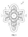
図1〜図3は、全体で、本開示による1つの例示的なクッションパッド100を示している。パッド100は、先に述べたように、肘関節の輪郭に適応された形状、サイズおよび構成を有するが、パッドが、具体的な設計または用途に関して実際的である、または望ましいような任意の形状、サイズまたは構造を含み得ることは理解されるべきである。図示されているように、パッド100は、前面10と、裏面12と、外側の縁/周囲14とを備える。図2および図3における断面に示されているように、パッド100は、任意選択の外側および内側の層16、17間に配置されるクッション層15と、クッション層15と内層17との間に配置される補強層Rとを備える。
1-3 generally illustrate one
図4〜図6は、全体で、本開示による例示的なクッションパッド200の別の実施形態を示している。図5および図6における断面に示されているように、パッド200は、前記パッド100に類似する構造を有していて、前面10と、裏面12と、外側の縁/周囲14とを備え、クッション層15が任意選択の外側および内側の層16、17間に配置され、かつ補強層「R」がクッション層15と内層17との間に配置されている。
4-6 generally illustrate another embodiment of an
パッド100、200は、内部に画定された複数のメダリオンを備え、かつ場合により、メダリオンの上面34内に1つまたは複数の溝42が形成されてもよい。パッド100、200は、複数のメダリオンを離隔された関係で保持するために、かつパッドにフレキシブルさを与えるために、ヒンジ38も備える。パッド200は、さらに、パッド周囲の形状に一致する周囲ヒンジ50を備える。ヒンジ38、50は、隣接するメダリオンの外周間のスペーシングによって画定される幅「W1」と、メダリオンの上面34とパッド200の上面10との間のスペーシングによって画定される深さ「D1」と、補強層R、外側および内側の層16、17およびもしあればこれらの層間に配置されるクッション材料15による結合厚さによって画定される厚さ「T2」とを有する。前述の構造体における補強材層Rは、構造体に、具体的にはヒンジ38、58において向上された引裂強さおよびフレキシブルさ、ならびに後述する他の利点を与える。図示されているように、層Rは、層15に隣接しかつその下に配置される。あるいは、所望されれば、層Rは、層Rが多孔質(多孔性)であることを条件として、層17へラミネートされることが可能である。あるいはまた、所望されれば、前述の構造体は、さらに、層Rと層17との間に配置される接着層(不図示)を含むことが可能である。
The
層15、層16および層17および(使用されれば)接着剤に適する材料は、前述の特許出願に、および各々参照によりその全体が開示に含まれる米国公報第US2008/0034614号および第US2009/0255625号に開示されている。
Materials suitable for
補強層Rの、層15、16、17に対する相対位置は、上述の構造に限定されず、所望される通りに変えられてもよい。さらに、層15、16、17および層Rのうちの任意のもの、または全てに使用される材料のタイプも、所望される通りに変えられてもよい。図3Aには、このような材料セクションの例示的な層状配置の幾つかが示されている。例えば、外層として織物層(ファブリック層)を用いることが望ましい実施形態によっては、内層17は、この織物層へラミネートされてもよく、補強層が層15、17間に配置される形で層15に隣接して配置されてもよい。実施形態によっては、セクションには、1つまたは複数の補強材層がクッション材層と上側および/または下側のバリア層との間に配置された状態で、バリア層の対向する上下層間に配置されるポリマー材料が含まれる可能性がある。前述の任意の実施形態において、セクションには、さらに、必要に応じて、または所望される通りに、任意の層間に配置される一層または複層の接着剤が含まれてもよい。さらに、これまでに述べた構造体は何れも、層の相対的方向性が上下逆さとなるように反転されてもよい(図示せず)。
The relative position of the reinforcing layer R with respect to the
補強材層Rに適する材料には、クッション材料がバリア層へ直に接触してこれに接着するように、成形プロセスの間にクッション材料が補強材の細孔または細隙を介して流れることを可能にする有孔性(多孔性)の材料が含まれるが、この限りではない。接着プロセスは、化学的、機械的、熱的などであっても、これらの組合せなどであってもよい。 Suitable materials for the reinforcement layer R include that the cushion material flows through the pores or slits of the reinforcement during the molding process so that the cushion material is in direct contact with and adheres to the barrier layer. This includes, but is not limited to, porous (porous) materials that enable it. The bonding process may be chemical, mechanical, thermal, etc., or a combination thereof.
適切な有孔補強材Rには、織布および不織布、編物(ニット)、スペーサファブリック、スクリム、交絡ポリエステル(ハイドロ交絡および/またはエア交絡を含む)などが含まれるが、この限りではない。補強層Rに適する他の材料には、編物または織物であって、やはりラミネートされる場合も浮動性である場合も含まれるが、この限りではない。編物(ニット)は、丸編み、縦編み、スペーサ編物などである可能性もある。有孔補強層Rの使用は、層が成形可能材料で飽和状態になると共に有孔層による僅かな表面剛性の形成を可能にし、これにより、衝撃時に余分な保護層が提供され、かつインサートの構造的一体性が追加される。 Suitable perforated reinforcements R include, but are not limited to, woven and non-woven fabrics, knitted fabrics, spacer fabrics, scrims, entangled polyesters (including hydroentangled and / or air entangled). Other materials suitable for the reinforcing layer R include, but are not limited to, knitted fabrics or woven fabrics, both laminated and floating. The knitted fabric (knit) may be circular knitting, warp knitting, spacer knitting, or the like. The use of the perforated reinforcing layer R allows the layer to become saturated with the moldable material and allows the perforated layer to form a slight surface stiffness, thereby providing an extra protective layer upon impact and the insert Structural integrity is added.
適切な不織材料には、エアレイド、スパンボンド、ポイントボンド、ステッチボンド、フォームなどが含まれるが、この限りではない。適切な不織材料の1つは、ハイドロ交絡ポリエステルであり、その重量は、1平方ヤード当たり約0.1オンスから約15オンスまでの範囲、より具体的には、1平方ヤード当たり約0.5オンスから約5オンスまでの範囲、かつさらに具体的には、1平方ヤード当たり約1オンスから約4オンスまでの範囲である。不織布であれば、層Rは、より少ない重量、嵩または経費のかからない布で、構造体内の折り畳みおよび/またはヒンジポイントにおける改良された引裂および屈曲を提供する。前述の改良は、任意選択の布および/またはライニングなしでも増大される。Rへの不織布の使用は、艶があり、防水性で洗浄可能な外面も提供し、同時になおも、縫い目における耐引裂性を提供する。ランダム不織繊維の優位点は、編物または織布とは対照的に、柔らかさが向上し、かつ屈曲または曲げられるとはじく傾向が低減される、またはなくされることにある。不織構造のランダム性は、柔らかさを向上させ、かつ実装によっては、折り目および/またはヒンジにおいて向上された引裂強さを提供する場合がある。 Suitable nonwoven materials include, but are not limited to airlaid, spunbond, pointbond, stitchbond, foam and the like. One suitable nonwoven material is hydro-entangled polyester, which weighs in the range of about 0.1 ounces to about 15 ounces per square yard, and more specifically about 0.000 per square yard. The range is from 5 ounces to about 5 ounces, and more specifically from about 1 ounce to about 4 ounces per square yard. If non-woven, layer R is a less weight, bulk or costly fabric and provides improved tearing and bending at the folding and / or hinge points in the structure. The aforementioned improvements are enhanced without optional fabrics and / or linings. The use of nonwovens for R provides a glossy, waterproof and washable outer surface while still providing tear resistance at the seam. The advantage of random nonwoven fibers is that, in contrast to knitted or woven fabrics, softness is improved and the tendency to repel when bent or bent is reduced or eliminated. The randomness of the nonwoven structure may improve softness and in some implementations may provide improved tear strength at the folds and / or hinges.
ケブラー(Kevlar)(商標)、金属織布または編織物を用いる補強層Rは、尖った物体による穿孔および/または突刺に対する保護を提供し、ワイヤメッシュまたは曲げることができる有孔物質の使用は、インサートを成形する能力を提供し、スペーサファブリックの使用は、引裂強さを向上させかつ追加的な撓み性衝撃層を提供し、エーロゲル不織布の使用は、超断熱を提供し、アウトラスト等の相変化ファブリックの使用は、エネルギー貯蔵特性を提供し、静電気放散性のファブリックまたは不織布の使用は、静電気放電を提供し、銀等の活性剤の使用は、抗菌活性等の性質を提供し、選択的にダイカットされるファブリックまたはスクリムの使用は、補強層の選択部分のサイズ、形状および位置合わせに依存する選択的延伸または強度の部位を提供し、シリコーンまたは他のプラスチックメッシュの使用は、耐熱性および/または強度を提供する。 Reinforcement layer R using Kevlar ™, metal woven or knitted fabric provides protection against piercing and / or piercing by pointed objects, the use of wire mesh or bendable porous materials Provides the ability to mold inserts, the use of a spacer fabric improves tear strength and provides an additional flexible impact layer, and the use of an airgel nonwoven provides super-insulation and phases such as outlast The use of change fabric provides energy storage properties, the use of static dissipative fabrics or nonwovens provides electrostatic discharge, the use of active agents such as silver provides properties such as antibacterial activity, and selective The use of a fabric or scrim that is die-cut into a part of the selective stretch or strength that depends on the size, shape and alignment of the selected part of the reinforcing layer It provides the use of a silicone or other plastic mesh provides heat resistance and / or strength.
内層、外層、補強層および/またはクッション層のうちの1つまたはそれ以上においては、活性剤の使用が望ましい。例えば、銀または銅ベースの活性剤を添加すると、材料に抗菌性または抗真菌性を与えることができる。内層または外層またはフォーム自体における活性剤の使用は、抗菌剤または抗真菌剤として作用するための銀または銅ベース活性剤の添加のように、望ましい。 In one or more of the inner layer, outer layer, reinforcing layer and / or cushion layer, the use of an active agent is desirable. For example, the addition of a silver or copper based activator can impart antibacterial or antifungal properties to the material. The use of active agents in the inner or outer layer or foam itself is desirable, such as the addition of silver or copper based active agents to act as antibacterial or antifungal agents.
本実施形態において、ヒンジ38、50でのクッション層15の厚さは、製造プロセス中に、ヒンジ38、50におけるその厚さがゼロに近づくように最小化される。その結果、ヒンジ38、50におけるクッション材料は、裸眼では見えない場合があり、または超高感度の厚さ計を用いなければ検出できない場合がある。
In this embodiment, the thickness of the
層間に留まる残りのクッション材料は、ヒンジ38、50において層同士を接着する手助けをする場合がある。使用される材料によって、層間の接着は、少なくとも部分的に化学的、熱的および/または機械的接着であってもよい。例えば、クッション層として使用される材料が樹脂であれば、ヒンジ38、50内の残留樹脂は、層を互いに接着するための接着剤として機能することができる。接着剤としての樹脂の使用は、極薄いヒンジ部位における別々の接着剤の必要性をなくし、かつ接着をパッドを通じて一貫してかつ等しく柔軟に保ち、これにより、パッドの耐久性が向上される、という理由で効果的である。
The remaining cushion material that remains between the layers may help bond the layers together at the
あるいは、層16、17のうちの一方として布が使用されれば、ヒンジ内の層間の接着は、樹脂が布内の開口または孔内へ圧搾される結果として、少なくとも部分的に機械的であってもよく、よって、層Rおよび層16、17の一部は製造中に接着し、その結果、接着された層16、17のアイランド間に接着層15、16、17の「アイランド(islands)」(島)が生じる。
Alternatively, if a fabric is used as one of the
ヒンジ38、50内のクッション層15を最小限に抑える又は無くすることにより、ヒンジのフレキシブルさ(柔軟性)は最大化され、よって、パッド200全体は、様々な方向へ曲がる、屈曲する、折り畳む、および捻れることができる。例えば、パッド200は、図5に示されているように、ヒンジ38、50に沿って矢印「A」の方向へ180度も曲がる、または屈曲することができる。反対方向「B」におけるフレキシブルさは、メダリオンの厚さおよびスペーシングによってのみ制限される。
By minimizing or eliminating the
本実施形態において、ヒンジ38、50における外側および内側の層16、17間の連続的な接着の存在は、メダリオンを所定位置に「ロック」し、パッドからクッション材料が出ることを最小限に抑えるか防止する、あるいは、流体等の物質がパッド内へ進入することを最小限に抑えるか防止する、という理由で効果的である。したがって、ヒンジ38、50は、そうでなければ層剥離に繋がりかねない流体および他の材料のパッドへの貫入を不可能にするように、パッド、具体的にはクッション材料を安定させる。さらに、ヒンジ部位における補強層Rの存在は、ヒンジ部位における引裂強さを増大させる。
In this embodiment, the presence of continuous adhesion between the outer and
パッドが前層、後層または双方の層と共に成形される場合、パッドの最大のフレキシブルさは、ヒンジの厚さが層15を除く層の組み合わされた厚さに略一致するとき、またはクッション層15の厚さがゼロに近似するときに達成されることがある。
If the pad is molded with the front layer, the back layer, or both layers, the maximum flexibility of the pad is when the thickness of the hinge approximately matches the combined thickness of the layers except
例えば、上述の実施形態において、外側および内側の層16、17の双方は、ヒンジ内を含むパッド全体に渡ってクッション層15へ連続式に接着される。パッドの構造によって、ヒンジ内の材料の量が最小限に抑えられるか、またはなくされる場合、外層および内層は、クッション層15へ接着されてもよく、または互いに接着されてもよい。前層をクッション層15へ接着する1つの重大な利点は、クッション層15の上下に連続する不断の表面を提供すること、即ち、パッドの外周部分を除いてクッション層15を封入することにある。ヒンジおよび/または溝はメダリオンより薄いことから、連続性の上下層は、ヒンジおよび溝部位を強化し、そうでなければ使用中のパッドの屈曲によって発生し得るヒンジおよび/または溝内の破損が最小限に抑えられる。少なくとも1つの接着層は、屈曲中の薄いヒンジ部位を保護するために使用されてもよい。熱可塑性ポリウレタンフィルムは、外層16として使用されると、ヒンジまたは溝内の層17の亀裂または破損を防止する上で特に優れている。内層は、フォームへ接着されていれば、ヒンジまたは溝へ力を与えることができ、または、多くの実施形態では、内層および外層の双方がフォームへ接着される。ヒンジの厚さが極小さい場合、特に、ヒンジ内にフィルムがほとんど存在しない、または全く存在しない場合、内側および外側双方の接着層は、補強層Rの有無に関わらず、パッドの構造的完全性(構造的一体性)を保持することが望ましい。内層および外層には、TPEフィルム(訳注:「TPE」とは、Thermo-Plastic Elastomer、熱可塑性エラストマーを意味する)、スパンデックスファブリックなどの、かなりの弾性を有する材料を用いることが望ましい。実施形態によっては、内層または外層として、積層式フィルム裏当てを有するファブリックを用いることが望ましい場合がある。ポリウレタンフィルム積層体等の、ファブリックとフィルムとの積層体である内層は、ヒンジの耐久性を最大化するために望ましい。
For example, in the embodiment described above, both the outer and
先に述べたように、本開示の別の態様は、身体の特定部位を保護するために、上述のパッドを、衣料品、具体的には弾性衣料へ組み込むことである。これまでに述べたパッドのうちの1つが、着用者にぴったりとフィットする弾性スリーブまたは衣料へ組み込まれる場合、ヒンジ式および/または溝付きの多層パッド構造体は、ヒンジ式パッドが保護されるべき部位にフィットして接触する形に保たれるようにして、スパンデックスファブリック、その他延伸可能な材料へ縫合、粘着または他の方法で付着される。パッドは、衣料品の内部または外部へ縫合されることが可能である。パッドには、スリーブがなおも著しく延伸して着用者にフィットできるように、スリーブの全外周の一部のみをカバーさせることが望ましい場合がある。独自的なヒンジ式保護パッドと弾性衣料との統合は、衣料品全体を替えることなく、重要な衝撃吸収パッドを特定の身体部位へ追加する単純な方法を作り上げることによって、特別な相乗効果をもたらす。 As previously mentioned, another aspect of the present disclosure is the incorporation of the above-described pad into a garment, specifically an elastic garment, to protect a particular part of the body. When one of the pads described so far is incorporated into an elastic sleeve or apparel that fits snugly into the wearer, the hinged and / or grooved multilayer pad structure should protect the hinged pad It is sutured, glued or otherwise attached to spandex fabric, or other stretchable material, so that it remains in contact with the site. The pad can be sewn into or out of the garment. It may be desirable for the pad to cover only a portion of the entire outer periphery of the sleeve so that the sleeve can still stretch significantly to fit the wearer. The integration of the unique hinged protective pad and elastic garment provides a special synergy by creating a simple way to add critical shock absorbing pads to specific body parts without changing the entire garment .
図7は、スリーブ(袖)の本体64へ付着されたクッションパッドを備える、圧縮(弾性)スリーブ300を示す。図示されているように、パッドは、使用時に中央のメダリオン18の位置がユーザの肘に一致するように、周囲フランジ40をスリーブ300の本体64へ綴じ付けることによってスリーブ300へ付着される。使用時に、ユーザの腕が曲げられると、フレキシブルなヒンジ38と溝42とのコンビネーションにより、パッドは、中央のメダリオン18の肘に対する位置合わせを保持しながら、ユーザの腕の曲がった構造へ適合することができる。
FIG. 7 shows a compression (elastic)
パッドが圧縮(弾性)スリーブと統合される場合、動作する関節を保護する他の方法に比べて、幾つかの固有の特性および利点が提供される。圧縮(弾性)スリーブへ組み込まれると、パッドは、保護されるべき関節と連続的に密接な接触状態になることが可能であるが、これは、適切に設計されたヒンジが、保護用スリーブが自然に正しい位置および方向性に留まることを可能にするという理由で、膝、肘、肩および足首等のフレキシブルな関節を保護する場合に望ましいことがある。ヒンジが適正に設計されると、保護用圧縮(弾性)スリーブは、腕と一体式に動き、従来のパッドより遙かに広い可動域を可能にする。 When the pad is integrated with a compression (elastic) sleeve, several unique properties and advantages are provided compared to other methods of protecting a working joint. When incorporated into a compression (elastic) sleeve, the pad can be in continuous and intimate contact with the joint to be protected, as the properly designed hinge is used by the protective sleeve. It may be desirable to protect flexible joints such as knees, elbows, shoulders and ankles because they naturally remain in the correct position and orientation. When the hinge is properly designed, the protective compression (elastic) sleeve moves integrally with the arm, allowing a much wider range of motion than conventional pads.
また、保護用スリーブが関節および皮膚と密接に接触した状態では、外部の物質からの衝撃後、パッドに起因して皮膚または関節に当たる追加的な衝撃は存在しない。より硬いパッドは、フレキシブルでもなく形状にフィットもしないことから、特定の身体部位または関節と連続的に密接な接触状態になり得ない場合がある。形状にぴったり合わなければ、パッドは、着用者を傷つける衝撃の一部となる場合がある。スリーブ構造のパッドは、広範な半径に渡って包むことができかつ、ある例によっては関節全体を包むことにより360度の保護を提供することによって、動作する関節を独自に、より良く保護することができる。概して、スリーブが延伸して腕への適合性を高めることができるように、圧縮(弾性)スリーブの幾分かの部位は、パッド層を追加せずに残すことが望ましい。 Also, when the protective sleeve is in intimate contact with the joint and skin, there is no additional impact on the skin or joint due to the pad after impact from external material. Stiffer pads may not be in close contact with a particular body part or joint because they are neither flexible nor fit in shape. If the shape does not fit exactly, the pad may become part of the impact that hurts the wearer. Sleeve-structured pads can be wrapped over a wide range of radii and in some cases provide 360 degrees of protection by wrapping the entire joint, thereby uniquely protecting the working joint Can do. Generally, it is desirable to leave some portions of the compression (elastic) sleeve without adding a pad layer so that the sleeve can be stretched to improve fit to the arm.
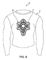
図8は、シャツの本体80へ付着されたクッションパッドを備える、圧縮(弾性)シャツ400を示す。図示されているように、パッドは、中央のメダリオン18の位置がユーザの胸の中心に一致するように、周囲フランジ40をシャツの本体80へ綴じ付けることによってシャツ400へ付着される。使用時に、フレキシブルなヒンジ38と溝42とのコンビネーションは、パッドが、パッドをユーザの体に近接して保持しながら、ユーザの胸の領域へ適合することを可能にし、これにより、ユーザが胸部域に衝撃を受けた場合のパッドの衝撃吸収能力が最大化される。衣料品は、皮膚層から湿気を逃がすように設計されるウィッキングファブリックからも製造されることが可能である。
FIG. 8 shows a compression (elastic)
また、本パッドは、保護機能を損なうことなく、空気および/または湿気の透過を強化するように設計される場合もあるが、他の保護パッドにこのオプションは存在しない。ヒンジ、溝および/またはメダリオンは、穿孔(図示略)を備えてもよく、これにより、湿気または空気の透過率が上がる。ウィック素材の内層としての使用、または内層であるTPEフィルム層との組合せによる使用は、心地よさも高めることができ、かつヒンジを介して湿気を逃がすことができる。また、高い水蒸気透過性(「MVT」)(moisture vapor transmissive)フィルム層の使用は、心地よさをさらに高めることができる。このようなフィルムは、化学的吸収/脱離によって機能することができる。このようなフィルムの例は、Omniflex社からSympatexまたはTX1540の商品名で販売されている。また、GoretexまたはPorelle(Porvair社)等の微孔質高MVTフィルム、または他の類似フィルムも使用可能である。 The pad may also be designed to enhance air and / or moisture permeation without compromising the protection function, but this option does not exist for other protection pads. The hinge, groove and / or medallion may be provided with perforations (not shown), thereby increasing moisture or air permeability. The use of the wick material as an inner layer, or in combination with the inner layer of the TPE film layer, can also increase comfort and allow moisture to escape through the hinge. Also, the use of a moisture vapor transmissive film layer can further enhance comfort. Such films can function by chemical absorption / desorption. Examples of such films are sold by Omniflex under the trade name Sympatex or TX1540. Also, microporous high MVT films such as Goretex or Porelle (Porair) or other similar films can be used.
本パッド/構造体は、前述の第’614号特許公報に開示されている技術を用いて製造されてもよい。本パッド用の金型は、化学的、熱的および/または機械的接着であり得る接着で層を互いに接着させながら、パッドの所定の実施形態ではヒンジ38、50におけるフォームを最小限に抑える、またはなくすに足る条件下で、層15、16、17、Rが互いに圧縮されることが可能であるように設計される。
The pad / structure may be manufactured using the techniques disclosed in the aforementioned '614 patent. The mold for the pad minimizes the foam at the
クッション層15用に、厚さゼロに接近する接着ヒンジを用いることは、極めてユニーク(独自的)である。このようなゼロに近い厚さのヒンジ部位において、外層の頂面は、なおもヒンジ全体にわたって内層へ接着され、これにより、特定の選択された部位における劇的に改良された可動域を可能にすることができる。記述しているように、ヒンジ部位は、クッション材料のより厚い部位より少ないことを条件として、ゼロに近い厚さ(フォームの0.001インチ(1ミル)未満)からの、またはこれより高い、何れかであることが可能である。実施形態の中には、ゼロに近いヒンジ部位を有するものがあり、一方で他のヒンジ部位は、0.010インチ(10ミル)、0.020インチ(20ミル)にあり、または0.080インチ(80ミル)または0.120インチ(120ミル)ですらある。複数の方向性におけるヒンジ部位および溝部位双方のコンビネーションは、必要とされる場合に全可動域を組み合わせるパッドの形成、但しさほど屈曲が要求されない他の部位における保護パッドの形成を可能にする。
The use of an adhesive hinge approaching zero thickness for the
ヒンジ部位の厚さがゼロに接近する付近、または薄いヒンジ部位(0.100インチ(100ミル)未満のフォーム)において、パッド全体が連続して接着された内層または外層(もしくは双方)を有する、という事実は、スペーシング(間隔)を保持し、かつ保護されない部位の分離を防止する。カット片は圧迫されると分離し、よってユーザは露出されて怪我を負う可能性があることから、これは、パッドを作るために別々のカット片が使用されるパッドとは対照的である。 In the vicinity of the hinge part thickness approaching zero, or in a thin hinge part (foam less than 0.100 inch (100 mils)), the entire pad has an inner layer or an outer layer (or both) bonded continuously, This fact preserves spacing and prevents separation of unprotected sites. This is in contrast to pads where separate cut pieces are used to make the pad, since the cut pieces will separate when squeezed, thus exposing the user to injury.
本パッドは、軽量でありながら、特定の身体部位へのより優れた保護を提供するように製造されることが可能であるが、これは、運動選手および活動的な個人にとって重大な利点である。 The pad can be manufactured to provide better protection to specific body parts while being lightweight, but this is a significant advantage for athletes and active individuals .
同様に、具体的にはヒンジが「ゼロに近い」ヒンジである場合、クッションパッドを通じたヒンジの「ネットワーク」が、パッドの耐久性をさらに向上させるが、それは、フォームまたはヒンジ部位内の他のクッション材料をなくす、または最小限に抑えることでヒンジ内の接着強さを増大させるからである。補強層が包含される場合、引裂強さは増大される。ヒンジ部位では、ヒンジ部位における残りのクッション材料がフォーム構造体(フォームの場合)を支持するには不十分であることから、接着強さが増大される。ヒンジ内にフォームが残れば、接着強さは、フォームの引裂強さまで制限されてもよい。したがって、フォームまたは他のクッション材料の厚さが最小限に抑えられると、裂けるべきフォームセルの薄壁は存在しないことから、ヒンジ内の接着は増大する。即ち、ヒンジ内にセル状のフォーム構造体が存在しなければ、流体および/または微粒子が周囲フランジを超えて浸透する空間はない。その結果、1つのメダリオンまたはヒンジが損傷される、または危うくされても、損傷が及び得る場所は隣接するパッドおよび/またはヒンジでしかないことから、パッド全体への損傷は最小限におさえられるか、部分的なものとなる。 Similarly, specifically when the hinge is a “near zero” hinge, the “network” of the hinges through the cushion pad further increases the durability of the pad, but it is This is because eliminating or minimizing the cushioning material increases the bond strength within the hinge. If a reinforcing layer is included, the tear strength is increased. At the hinge site, the bond strength is increased because the remaining cushion material at the hinge site is insufficient to support the foam structure (in the case of foam). If foam remains in the hinge, the bond strength may be limited to the tear strength of the foam. Thus, when the thickness of the foam or other cushioning material is minimized, adhesion within the hinge is increased because there is no thin wall of foam cell to tear. That is, if there is no cellular foam structure in the hinge, there is no space for fluid and / or particulates to penetrate beyond the surrounding flange. As a result, if a single medallion or hinge is damaged or compromised, damage to the entire pad is minimized because the damage can only be made to the adjacent pads and / or hinges. , Become partial.
本開示の別の態様は、具体的にはケースの縁における衝撃保護の向上、さらなる軽量化、審美性の向上、製造コストの低減、およびケースに入れる物品の摩耗の低減をもたらす、改良されたケースである。本開示の改良されたケースは、保護されるべき物品の外面に略適合する分離可能な内側および外側の相互接続パーツを備える。本保護ケースは、これまでに述べたものに加えて、保護を必要とする任意タイプの製品用に適合化されることが可能である。 Another aspect of the present disclosure is improved, specifically resulting in improved impact protection at the edge of the case, further weight savings, improved aesthetics, reduced manufacturing costs, and reduced wear on articles placed in the case. It is a case. The improved case of the present disclosure comprises separable inner and outer interconnect parts that generally conform to the outer surface of the article to be protected. The protective case can be adapted for any type of product that requires protection, in addition to those previously described.
図9〜図15は、全体で、携帯電話のための保護ケースに関連する本開示の例示的な一実施形態を示している。本明細書では、携帯電話を参照して説明を行っているが、一般的な当業者には、本ケースが、様々なアプリケーション(応用例)において、保護を必要とする任意タイプの製品用に使用され得ることが理解されるであろう。例えば、本明細書に記述される概念は、iPad(商標)等のデバイス用のより大きいケース、ハードシェルの付いた任意の鞄、運動用防護服などにも当てはまる。したがって、ケース本体およびインサートは、中に入れる製品の外面へ少なくとも部分的に適合する形状に形成されることが可能である。 9-15 generally illustrate an exemplary embodiment of the present disclosure related to a protective case for a mobile phone. Although described herein with reference to a mobile phone, the general person skilled in the art will recognize that this case is suitable for any type of product that requires protection in various applications. It will be understood that it can be used. For example, the concepts described herein also apply to larger cases for devices such as iPad ™, any heel with a hard shell, athletic protective clothing, and the like. Thus, the case body and the insert can be formed into a shape that at least partially conforms to the outer surface of the product to be contained.
図9に示されているように、ケース500は、ケースインサート600と、ケース本体700とを備える。ケースインサート600は、ケースインサート600に入れるための物品、本例では携帯電話の外面の少なくとも一部に適合するように構築されてもよく、かつケース本体700は、ケースインサート600の少なくとも一部の外面に適合するように構築されてもよい。
As shown in FIG. 9, the
ケース本体700は、図10にさらに詳しく示されている。図示されているように、ケース本体700は、内面702と、外面704と、これらを通じて延びる複数の開口706とを備える。また、ケース本体700は、1つまたは複数の開口または孔708も含んでもよく、その形状、サイズおよびロケーション(位置)は、機能キーまたは他のアイテム(充電ポート、アンテナ、カメラのファインダなど)のサイズ、形状およびロケーション(位置)に対応して、このようなアイテムを障害物のない状態に保持する。
The
ケース本体700は、略硬質、半硬質および/または軟質材料で製造されてもよい。硬質である場合、ケース本体700は、典型的には携帯電話カバーに使用されるタイプの硬質プラスチック材料から製造されてもよい。ケース本体700は、ケース本体の内面と携帯電話の外面との間にケースインサートを置けるだけのスペース(空間)を含んで、ケースインサートに対応するサイズおよび構造を有する。
図示されているように、ケース本体700は、1つの単一パーツとして示されているが、所望されれば、ケース本体は、携帯電話の前面および裏面へ組み立てられる、連動エッジの付いた2つ以上のパーツとして製造されてもよい。同様に、ケースインサート600も、各ケース本体部分に対応する、かつ組立て前に各ケース本体部分へ挿入されることが可能な2つの別々のパーツとして製造されてもよい。
As shown, the
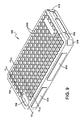
図11は、ケースインサート600をより詳しく示している。ケースインサート600は、ケースインサート600に入れるための物品、本例では携帯電話の外面の少なくとも一部に適合するように構築されてもよい。この例示的実施形態において、ケースインサート600は、離隔された外側および内側の表面602、604と、外面604内に画定されかつ外面604から上方へ延びる、ケース本体700内に配置された(先に述べたような)開口706に対応する複数のメダリオン(以下、「バンパ618」)とを備える。バンパ618は、先に述べたように、チャネルによって互いから離隔され、かつ所望される通りに変わり得る厚さT1および幅W1を有する。バンパ618は、チャネルの厚さT1より大きい厚さT3を有し、かつインサートの外面より上へ厚さT2だけ突き出す。
FIG. 11 shows the
前述の厚さ、幅およびスペーシングは全て、所望される通りに変わってもよい。 All of the aforementioned thicknesses, widths and spacings may vary as desired.
バンパ618は、上面618aと、上面618aから下へ延びる側壁618bとを備える。バンパ618は、ケース本体700の外面より上へ突き出すことによって、保護効果または心地よい効果を提供するに足る任意の厚さを有してもよい。したがって、所定の機能的効果のために、バンパ618の厚さは、組み立てられた場合の構造でケース外面より上へ突き出すように設計されてもよい。例えば、例示的な本携帯電話デバイスのケースでは、バンパ618は、ケースインサート600の外面より上へ約1/16インチから約1/2インチだけ突き出してもよい。所望されれば、または必要であれば、ケースインサート600は、落下に際して画面を保護するために画面側面(例えば、ベゼル(bezel))に隣接して突き出すように設計されるバンパも備えることができる。
The
ケースインサート600の厚さは、所望される通りに変えられてもよいが、ケースの総重量を最小限に抑えるだけの薄さでありながら、デバイスを衝撃から保護するに足る厚さであることが望ましい。 The thickness of the case insert 600 may vary as desired, but should be thin enough to protect the device from impact while being thin enough to minimize the total weight of the case Is desirable.
所望されれば、ケースインサート600は、フォームの一部が、画面側面(図示略)を保護するための軟らかいベゼルとして作用すべくガラス画面上へ突き出すように製造されることが可能である。 If desired, the case insert 600 can be manufactured such that a portion of the foam projects onto the glass screen to act as a soft bezel to protect the screen side (not shown).
本明細書では略正方形として示されているが、バンパ618は、衝撃保護という機能上の効果、または消費者にアピールするための美的設計を達成するように、所望される通りの任意の形状または構造を有してもよい。バンパのサイズ、形状、数量、構造およびロケーション(位置)は、前述の目的を達成すべく所望される通りに変えられてもよい。審美性を目的として、ケース本体およびインサートの色は、同じであっても、異なってもよく、それらはまた、グラフィック(画像)の使用に順応してもよい。
Although shown herein as generally square, the
また、ケースインサート600は、ケース本体700内のものに対応する1つまたは複数の開口または孔620も備え、その形状、サイズおよびロケーション(位置)は、機能キー、または障害物のない状態に置かれなければならない他のアイテム(充電ポート、アンテナ、カメラのファインダなど)のサイズ、形状およびロケーション(位置)に対応する。
The
所望されれば、ケースインサート600は、フォームの一部が、画面側面(図示略)を保護するための軟らかいベゼル(bezel)(枠)として作用すべくガラス画面上へ突き出すように製造されることが可能である。 If desired, the case insert 600 may be manufactured such that a portion of the foam projects onto the glass screen to act as a soft bezel to protect the screen side (not shown). Is possible.
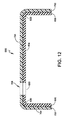
図11には、ケースインサート600が、ケース本体700へ挿入される前の平坦な、または広げられた形状で示されている。ケース本体700へのケースインサート600の挿入を容易にするために、ケースインサート600は、携帯電話の輪郭、縁および/または角に対応する折り目630および/または折り畳み領域630’(図16において最もよく分かる)も備えてもよい。所望されれば、折り目630および/または折り畳み領域630’は、スペーサ域Sの厚さT1より少ない厚さT4を有してもよい。
In FIG. 11, the
図15は、ケース本体700へ挿入されつつあるケースインサート600を示す。先に述べたように、平坦な形状にある場合、ケースインサートは、折り目630を含んでもよい。したがって、組立てに際して、ケースインサートは、対応するバンパおよび開口が揃えられかつケース上面から突き出るまでバンパが対応する開口へ挿入されるようにして、折り目630および/または折り畳み領域630’に沿って折り畳まれ、ケースに挿入される。
FIG. 15 shows the case insert 600 being inserted into the
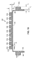
組み立てられると、バンパは、ケース本体上の対応する開口から突き出し、かつバンパ間のスペーサ域Sは、バンパ間でケース本体より下に配置される。突き出すバンパは、少なくともケース本体を衝撃から保護する機能を果たし、かつケース本体の下に配置されるスペーサ域も、デバイスとケース本体との間に配置される材料を介してエネルギーを吸収する。したがって、ケース10は、独自の特徴である、外側にバンパが露出され、かつ内側ではケースインサートがケース本体の下に配置される結果として、耐衝撃性およびエネルギー吸収性を提供する。本明細書では、バンパ618を開口706がその内部に受け入れるように適合化されて示されているが、本ケース本体は、バンパ618を内部に受け入れるために、開口ではなく、窪んだ領域(不図示)を備えるように形成されることも可能である。
When assembled, the bumper protrudes from a corresponding opening on the case body, and the spacer area S between the bumpers is disposed below the case body between the bumpers. The protruding bumper functions to protect at least the case body from impact, and the spacer area disposed under the case body also absorbs energy through the material disposed between the device and the case body. Thus, the
先の実施形態におけるものと同じケース本体700を備える、ケースの別の実施形態500’を、図16〜図19を参照して示す。ケースインサート600’は、ケースインサート600に類似する構造を有し、かつさらに、折り目630ではなく折り畳み領域630’を含む。
Another embodiment 500 'of the case comprising the
先に述べたように、ケース本体およびケースインサート双方の色および/またはパターンは、審美的理由で替えられてもよい。ケースは、消費者がケース本体とケースインサートとを希望通りに交換できるように、異なる色、パターンおよび/またはグラフィック(画像)を有する2つ以上のケース本体および/または2つ以上のケースインサートを備えるキットとして販売されてもよい。 As stated above, the color and / or pattern of both the case body and the case insert may be changed for aesthetic reasons. The case may include two or more case bodies and / or two or more case inserts having different colors, patterns and / or graphics (images) so that the consumer can exchange the case body and the case insert as desired. It may be sold as a kit provided.
図示されているように、セクション100は、上側のバリア層と下側のファブリック層との間に配置されるポリマー材料を含む。あるいは、セクション200は、下側のバリア層がファブリック層へラミネートされた状態で、上下バリア層間に配置されるポリマー材料を含んでもよい。また更に、セクション300は、2つのファブリック材料層であって、その2つのファブリック材料層の一方が上下バリア層の各々に隣接して配置されるものを備えてもよく、そして、補強層が両バリア層の各々に隣接して配置されてもよい。
As shown,
フォームを含む多くの材料は、摩耗および擦過によって経時的に劣化する場合があり、これにより、デバイス内へ透通して機能障害を発生させ得る粒子が生じる。未加工のフォームセルを露出させることは、フォームセルが汚れまたは塵を閉じ込めて美的でなくなり、かつデバイスを擦傷する可能性もあることから望ましくない。したがって、成形フォームには、適切な美観および/または、それが露出される外層として使用される場合には表面特性を提供するために、適切な頂面を接着させることが望ましい場合もある。これは、フィルム、フィルムラミネート、もしくは織物もしくは皮、又は、これらの組合せである可能性もある。 Many materials, including foams, can degrade over time due to wear and abrasion, resulting in particles that can penetrate into the device and cause functional failure. Exposing the raw foam cells is undesirable because the foam cells trap dirt or dust and become aesthetic and can scratch the device. Thus, it may be desirable for the molded foam to have a suitable top surface to provide the proper aesthetics and / or surface properties when used as an exposed outer layer. This can be a film, a film laminate, or a fabric or skin, or a combination thereof.
ケースインサート600の対向する両面の一方または双方上に保護層またはバリア層を包含することによるケースインサート600フォームの封入は、摩耗、擦過、微粒子形成を防止する、または最小限に抑えることができ、かつフォームに対する湿気防止を提供することができる。したがって、ケースインサートは、連続して接着される上面層を有する柔らかいフォームパーツ等の複数の層を備えることができ、柔らかいパーツの上面は、硬質ケース内の開口を介して突き出す。このようなケースにおいて、平坦な側面層または底層の織物またはフィルムは、ケースのライニングを作るように選択されることが可能である。インサート全体に渡って延びる連続する接着フィルムまたはファブリック層は、連続層のないフォームよりも実質的に向上した耐久性を提供する。 Encapsulating the case insert 600 foam by including a protective or barrier layer on one or both opposing sides of the case insert 600 can prevent or minimize wear, abrasion, particulate formation, In addition, moisture prevention for the foam can be provided. Thus, the case insert can comprise a plurality of layers, such as a soft foam part having a top surface layer that is bonded together, the upper surface of the soft part protruding through an opening in the hard case. In such cases, a flat side layer or bottom layer fabric or film can be selected to make the lining of the case. A continuous adhesive film or fabric layer extending across the insert provides substantially improved durability over foam without a continuous layer.
連続する接着フィルムが使用される場合、バンパ間に配置されるケースインサートの厚さは、0.020インチ(20/1000インチ)からの範囲であってもよいが、これより厚い、または薄い可能性もあり、または(全体的な衝撃保護が不要であれば)ゼロである可能性もある。衝撃吸収用には、大きすぎる厚さを追加することなく、約0.020インチから約0.060インチまでの厚さが望ましい。バンパの全体(開口フォーム間)および外部への延伸およびサイズを変える能力は、ケースの衝撃からの保護およびデバイスの打撃からの保護の双方において重要である。これらの厚さは、カメラケース、レンズケース、鞄、ipad(商標)等の他のデバイス用に必要に応じてカスタマイズされることが可能である。 If a continuous adhesive film is used, the thickness of the case insert placed between the bumpers may range from 0.020 inches (20/1000 inches), but can be thicker or thinner Or it may be zero (if overall shock protection is not needed). For shock absorption, a thickness of about 0.020 inches to about 0.060 inches is desirable without adding too much thickness. The ability to change the overall bumper (between the open foam) and outward stretch and size is important both in protecting the case from impact and from protecting the device. These thicknesses can be customized as needed for other devices such as camera cases, lens cases, bags, ipad ™.
電子デバイスの保護ケースとして使用される硬質プラスチックケースの1つの欠点は、デバイスが落下した場合にケースが割れることが多く、ケースを交換しなければならないことにある。本保護ケースは、突き出している隆起した衝突域がまず衝撃を削ぐことから、硬質ケースを破壊から保護するという追加の優位点を有する。 One drawback of a hard plastic case used as a protective case for electronic devices is that if the device falls, the case often breaks and must be replaced. The protective case has the additional advantage of protecting the hard case from breakage, since the protruding raised impact zone first scrapes the impact.
多くの保護ケースにおける別の欠点は、内部のデバイスが正面又は背面の衝撃からよりも側面又は縁側の衝撃からの方が破壊されやすいことにある。本ケースでは、インサートにPORON XRDのような衝撃吸収フォームを用いることで、このような衝撃からの保護を提供する。 Another drawback in many protective cases is that internal devices are more susceptible to destruction from side or edge impacts than from front or back impacts. In this case, the use of an impact absorbing foam such as PORON XRD for the insert provides protection from such an impact.
本明細書における「第1」、「第2」などの用語は、順序または重要性を示すものではなく、あるエレメントを別のエレメントから区別するために使用され、かつ本明細書における不定冠詞は、量的制限を示すものではなく、参照されるアイテムのうちの少なくとも1つの存在を示すものであることは留意されるべきである。同様に、「底」および「上」という言い回しは、本明細書では、別段の指摘のない限り、単に説明の便宜上使用されるものであり、任意の1つのポジションまたは空間的方向性に限定されないことも留意されるべきである。さらに、量に関連して使用される修飾成句「約」は、記載値を含むものであって、文脈により示される意味を有する(例えば、具体的な量の測定に関連づけられる誤差の度合いを含む)。 Terms such as “first”, “second”, etc. in this specification do not indicate order or importance, are used to distinguish one element from another, and the indefinite article in this specification is It should be noted that it does not indicate a quantitative limit, but rather indicates the presence of at least one of the referenced items. Similarly, the phrases “bottom” and “top” are used herein for convenience only and are not limited to any one position or spatial orientation unless otherwise indicated. It should also be noted. Further, the modifier “about” used in connection with a quantity is inclusive of the stated value and has the meaning indicated by the context (eg, including the degree of error associated with a particular quantity measurement). ).
化合物は、標準的な命名法を用いて記述されている。例えば、指摘された基により置換されないポジションは何れも、その原子価が指摘された通りの化学結合で充填されているものと理解され、または2つのアルファベットまたは記号間でない水素原子Aダッシュ(「−」)は、置換基の付着点を指すために使用される。例えば、−CHOは、カルボニル基の炭素を介して付着される。本明細書において別段の規定のない限り、本明細書における百分率は全て、重量パーセント(「wt.%」)を意味する。さらに、本明細書に開示されている全ての範囲は、包含的でありかつ結合可能である(例えば、「約25重量パーセント(wt.%)まで、望ましくは約5wt.%から約20wt.%まで、より望ましくは約10wt.%から約15wt.%まで」の範囲は、これらの端点およびその範囲内の全ての中間値、例えば「約5wt.%から約25wt.%まで、約5wt.%から約15wt.%まで」、他を含む)。「+/−10%」という表記は、指示される測定値が、記載値のマイナス10%の量からプラス10%の量までであり得ることを意味する。 Compounds are described using standard nomenclature. For example, any position not substituted by the indicated group is understood to be filled with a chemical bond whose valence is as indicated, or a hydrogen atom A dash that is not between two alphabets or symbols (“− ")" Is used to refer to the point of attachment of the substituent. For example, -CHO is attached through the carbon of the carbonyl group. Unless otherwise specified herein, all percentages herein refer to weight percent (“wt.%”). Further, all ranges disclosed herein are inclusive and bindable (eg, “up to about 25 weight percent (wt.%), Desirably from about 5 wt.% To about 20 wt.%). , More desirably from about 10 wt.% To about 15 wt.%, Ranges from these endpoints and all intermediate values within that range, such as “from about 5 wt.% To about 25 wt.%, About 5 wt. To about 15 wt.% ", Including others). The notation “+/− 10%” means that the indicated measured value can be from an amount of minus 10% to an amount of plus 10% of the stated value.
最後に、別段の規定のない限り、本明細書において使用される技術用語および科学用語は、本開示が属する分野の当業者によって一般的に理解されるものと同じ意味を有する。 Finally, unless defined otherwise, technical and scientific terms used herein have the same meaning as commonly understood by one of ordinary skill in the art to which this disclosure belongs.
本開示を例示的な実施形態を参照して記述したが、当業者には、本開示におけるエレメントについては、開示の範囲を逸脱することなく、様々な変更が行われてもよく、かつ等価物により置換されてもよいことが理解されるであろう。さらに、本開示の教示内容に対しては、その本質的範囲を逸脱することなく、特定の状況または材料を適合させるために多くの変形が行われてもよい。したがって、本開示は、本開示を実行するために企図される最良の態様として開示された特定の実施形態に限定されず、開示は、添付の請求の範囲に含まれる全ての実施形態を包含することが意図されている。 Although the present disclosure has been described with reference to exemplary embodiments, it will be apparent to those skilled in the art that various modifications may be made in the elements of the present disclosure without departing from the scope of the disclosure and equivalents thereof. It will be understood that may be substituted by: In addition, many modifications may be made to adapt a particular situation or material to the teachings of the disclosure without departing from the essential scope thereof. Accordingly, this disclosure is not limited to the specific embodiments disclosed as the best mode contemplated for carrying out this disclosure, and the disclosure encompasses all embodiments that fall within the scope of the appended claims. Is intended.
Claims (7)
前記第2のバリア層と前記フォーム層との間に配置される補強層と、
を備えるクッション材料構造体。 A foam layer (foam layer) disposed between opposing first and second barrier layers;
A reinforcing layer disposed between the second barrier layer and the foam layer;
A cushion material structure comprising:
Applications Claiming Priority (3)
| Application Number | Priority Date | Filing Date | Title |
|---|---|---|---|
| US201261612949P | 2012-03-19 | 2012-03-19 | |
| US61/612,949 | 2012-03-19 | ||
| PCT/US2013/033016 WO2013142523A1 (en) | 2012-03-19 | 2013-03-19 | Protective impact absorbing structures with internal reinforcement and materials therefor |
Related Child Applications (1)
| Application Number | Title | Priority Date | Filing Date |
|---|---|---|---|
| JP2018090426A Division JP2018131724A (en) | 2012-03-19 | 2018-05-09 | Impact absorbing protective structure having internal reinforcement and its material |
Publications (2)
| Publication Number | Publication Date |
|---|---|
| JP2015512358A true JP2015512358A (en) | 2015-04-27 |
| JP2015512358A5 JP2015512358A5 (en) | 2016-05-12 |
Family
ID=49158051
Family Applications (2)
| Application Number | Title | Priority Date | Filing Date |
|---|---|---|---|
| JP2015501860A Pending JP2015512358A (en) | 2012-03-19 | 2013-03-19 | Shock absorbing protective structure with internal reinforcement and its material |
| JP2018090426A Pending JP2018131724A (en) | 2012-03-19 | 2018-05-09 | Impact absorbing protective structure having internal reinforcement and its material |
Family Applications After (1)
| Application Number | Title | Priority Date | Filing Date |
|---|---|---|---|
| JP2018090426A Pending JP2018131724A (en) | 2012-03-19 | 2018-05-09 | Impact absorbing protective structure having internal reinforcement and its material |
Country Status (9)
| Country | Link |
|---|---|
| US (2) | US20130244526A1 (en) |
| EP (1) | EP2828074A4 (en) |
| JP (2) | JP2015512358A (en) |
| KR (1) | KR20140142301A (en) |
| CN (1) | CN104321189A (en) |
| CA (1) | CA2868027A1 (en) |
| GB (1) | GB2516184B (en) |
| RU (1) | RU2014141977A (en) |
| WO (1) | WO2013142523A1 (en) |
Families Citing this family (10)
| Publication number | Priority date | Publication date | Assignee | Title |
|---|---|---|---|---|
| EA028487B1 (en) | 2010-08-11 | 2017-11-30 | ДЖИ-ФОРМ, ЭлЭлСи | Cushioning pad |
| US9615611B2 (en) * | 2011-08-11 | 2017-04-11 | G-Form, LLC | Breathable impact absorbing cushioning and constructions |
| US20130303041A1 (en) * | 2012-03-14 | 2013-11-14 | Applied Ft Composite Solutions Inc. | Composite cushioning material with multiple strata |
| GB2502351A (en) * | 2012-05-23 | 2013-11-27 | Sanseva Ltd | A housing for an electronic device comprising cleaning material |
| CN104191701B (en) * | 2014-08-12 | 2016-04-13 | 隆扬电子(昆山)有限公司 | A kind of buffering, dustproof foam and production technology thereof |
| US10064273B2 (en) | 2015-10-20 | 2018-08-28 | MR Label Company | Antimicrobial copper sheet overlays and related methods for making and using |
| US10245809B2 (en) * | 2016-10-02 | 2019-04-02 | Pu Feng Enterprise Corp. | Heterogeneous composites and products thereof |
| JP6442105B1 (en) | 2017-07-14 | 2018-12-19 | カルソニックカンセイ株式会社 | Double pipe and method for manufacturing the same |
| US11793244B2 (en) * | 2020-06-08 | 2023-10-24 | Unstoppable Protective Gear, LLC | Athletic protective breast cup |
| KR102378772B1 (en) * | 2021-01-14 | 2022-03-28 | 배은정 | Shock absorbable work shirt |
Citations (6)
| Publication number | Priority date | Publication date | Assignee | Title |
|---|---|---|---|---|
| JPS6226193Y2 (en) * | 1981-09-04 | 1987-07-04 | ||
| JPH04110505U (en) * | 1991-03-15 | 1992-09-25 | 日本バイリーン株式会社 | Toe protection pads |
| JP3125428U (en) * | 2006-07-03 | 2006-09-21 | 株式会社アシックス | protector |
| US20090186189A1 (en) * | 2006-04-28 | 2009-07-23 | Lenzing Aktiengesellschaft | Hydroentangled Product Comprising Cellulose Fibers |
| US20120011656A1 (en) * | 2009-03-18 | 2012-01-19 | Patrick Noel Daly | Cushion, kit and method of manufacture |
| WO2012021737A1 (en) * | 2010-08-11 | 2012-02-16 | G-Form, LLC | Flexible cushioning pads, items incorporating such pads, and methods of making and using |
Family Cites Families (9)
| Publication number | Priority date | Publication date | Assignee | Title |
|---|---|---|---|---|
| JP3188936B2 (en) * | 1996-04-26 | 2001-07-16 | モリト株式会社 | Sports buttocks protector |
| US7147911B2 (en) * | 1996-11-12 | 2006-12-12 | Solidawater Holdings | Waterproof/breathable technical apparel |
| US20050034330A1 (en) * | 1996-11-12 | 2005-02-17 | Baychar | Running shoes, hiking shoes and boots, snowboard boots, alpine boots, hiking boots, and the like, having waterproof/breathable moisture transfer characteristics |
| JP3759042B2 (en) * | 2002-01-21 | 2006-03-22 | 株式会社モルテン | Supporter |
| JP4547546B2 (en) * | 2004-03-31 | 2010-09-22 | 本田技研工業株式会社 | Lumbar protection pad |
| TWI609788B (en) * | 2008-04-14 | 2018-01-01 | 波利渥克股份有限公司 | Deep draw method of making impact and vibration absorbing articles and the articles formed thereby |
| US8256034B2 (en) * | 2008-08-01 | 2012-09-04 | Nike, Inc. | Article of apparel with inner and outer layer and an insert element in between |
| US8186514B2 (en) * | 2008-10-14 | 2012-05-29 | Samsill Corporation | Transparent carrying case for portable electronic devices |
| MX2011005413A (en) * | 2008-11-24 | 2011-11-18 | Applied Ft Composite Solutions Inc | Resilient pad composite and process for making same. |
-
2013
- 2013-03-19 EP EP13764650.1A patent/EP2828074A4/en not_active Withdrawn
- 2013-03-19 CN CN201380026204.6A patent/CN104321189A/en active Pending
- 2013-03-19 US US13/847,422 patent/US20130244526A1/en not_active Abandoned
- 2013-03-19 JP JP2015501860A patent/JP2015512358A/en active Pending
- 2013-03-19 WO PCT/US2013/033016 patent/WO2013142523A1/en active Application Filing
- 2013-03-19 CA CA2868027A patent/CA2868027A1/en not_active Abandoned
- 2013-03-19 KR KR1020147029381A patent/KR20140142301A/en not_active IP Right Cessation
- 2013-03-19 RU RU2014141977A patent/RU2014141977A/en not_active Application Discontinuation
- 2013-03-19 GB GB1418560.7A patent/GB2516184B/en not_active Expired - Fee Related
-
2016
- 2016-10-18 US US15/297,101 patent/US20170036416A1/en not_active Abandoned
-
2018
- 2018-05-09 JP JP2018090426A patent/JP2018131724A/en active Pending
Patent Citations (6)
| Publication number | Priority date | Publication date | Assignee | Title |
|---|---|---|---|---|
| JPS6226193Y2 (en) * | 1981-09-04 | 1987-07-04 | ||
| JPH04110505U (en) * | 1991-03-15 | 1992-09-25 | 日本バイリーン株式会社 | Toe protection pads |
| US20090186189A1 (en) * | 2006-04-28 | 2009-07-23 | Lenzing Aktiengesellschaft | Hydroentangled Product Comprising Cellulose Fibers |
| JP3125428U (en) * | 2006-07-03 | 2006-09-21 | 株式会社アシックス | protector |
| US20120011656A1 (en) * | 2009-03-18 | 2012-01-19 | Patrick Noel Daly | Cushion, kit and method of manufacture |
| WO2012021737A1 (en) * | 2010-08-11 | 2012-02-16 | G-Form, LLC | Flexible cushioning pads, items incorporating such pads, and methods of making and using |
Also Published As
| Publication number | Publication date |
|---|---|
| GB201418560D0 (en) | 2014-12-03 |
| RU2014141977A (en) | 2016-05-20 |
| EP2828074A1 (en) | 2015-01-28 |
| JP2018131724A (en) | 2018-08-23 |
| WO2013142523A1 (en) | 2013-09-26 |
| US20130244526A1 (en) | 2013-09-19 |
| CA2868027A1 (en) | 2013-09-26 |
| US20170036416A1 (en) | 2017-02-09 |
| CN104321189A (en) | 2015-01-28 |
| EP2828074A4 (en) | 2015-04-22 |
| KR20140142301A (en) | 2014-12-11 |
| GB2516184B (en) | 2016-07-20 |
| GB2516184A (en) | 2015-01-14 |
Similar Documents
| Publication | Publication Date | Title |
|---|---|---|
| JP2018131724A (en) | Impact absorbing protective structure having internal reinforcement and its material | |
| JP6117770B2 (en) | Protective case and manufacturing method thereof | |
| JP5976646B2 (en) | Flexible cushion pad, item incorporating the pad, and method of manufacture and use | |
| KR102132731B1 (en) | Breathable impact absorbing cushioning and constructions | |
| EP2967161B1 (en) | Protective pad using a damping component | |
| US20180144410A1 (en) | Flexible Cushioning Pads, Items Incorporating Such Pads, and Methods of Making and Using |
Legal Events
| Date | Code | Title | Description |
|---|---|---|---|
| A521 | Request for written amendment filed |
Free format text: JAPANESE INTERMEDIATE CODE: A523 Effective date: 20160316 |
|
| A621 | Written request for application examination |
Free format text: JAPANESE INTERMEDIATE CODE: A621 Effective date: 20160316 |
|
| A131 | Notification of reasons for refusal |
Free format text: JAPANESE INTERMEDIATE CODE: A131 Effective date: 20170509 |
|
| A601 | Written request for extension of time |
Free format text: JAPANESE INTERMEDIATE CODE: A601 Effective date: 20170727 |
|
| A02 | Decision of refusal |
Free format text: JAPANESE INTERMEDIATE CODE: A02 Effective date: 20180109 |