JP2015199470A - vehicle control system - Google Patents
vehicle control system Download PDFInfo
- Publication number
- JP2015199470A JP2015199470A JP2014081005A JP2014081005A JP2015199470A JP 2015199470 A JP2015199470 A JP 2015199470A JP 2014081005 A JP2014081005 A JP 2014081005A JP 2014081005 A JP2014081005 A JP 2014081005A JP 2015199470 A JP2015199470 A JP 2015199470A
- Authority
- JP
- Japan
- Prior art keywords
- battery
- power
- voltage battery
- vehicle
- high voltage
- Prior art date
- Legal status (The legal status is an assumption and is not a legal conclusion. Google has not performed a legal analysis and makes no representation as to the accuracy of the status listed.)
- Pending
Links
- 230000001172 regenerating effect Effects 0.000 claims description 16
- 239000000446 fuel Substances 0.000 claims description 12
- 230000001133 acceleration Effects 0.000 claims description 4
- 230000003247 decreasing effect Effects 0.000 abstract 2
- 230000007423 decrease Effects 0.000 description 15
- 238000006243 chemical reaction Methods 0.000 description 3
- 230000005540 biological transmission Effects 0.000 description 1
- 238000010586 diagram Methods 0.000 description 1
- 230000000694 effects Effects 0.000 description 1
- 239000003507 refrigerant Substances 0.000 description 1
Images


Classifications
-
- H—ELECTRICITY
- H02—GENERATION; CONVERSION OR DISTRIBUTION OF ELECTRIC POWER
- H02J—CIRCUIT ARRANGEMENTS OR SYSTEMS FOR SUPPLYING OR DISTRIBUTING ELECTRIC POWER; SYSTEMS FOR STORING ELECTRIC ENERGY
- H02J7/00—Circuit arrangements for charging or depolarising batteries or for supplying loads from batteries
- H02J7/007—Regulation of charging or discharging current or voltage
- H02J7/007188—Regulation of charging or discharging current or voltage the charge cycle being controlled or terminated in response to non-electric parameters
- H02J7/007192—Regulation of charging or discharging current or voltage the charge cycle being controlled or terminated in response to non-electric parameters in response to temperature
- H02J7/007194—Regulation of charging or discharging current or voltage the charge cycle being controlled or terminated in response to non-electric parameters in response to temperature of the battery
-
- B—PERFORMING OPERATIONS; TRANSPORTING
- B60—VEHICLES IN GENERAL
- B60K—ARRANGEMENT OR MOUNTING OF PROPULSION UNITS OR OF TRANSMISSIONS IN VEHICLES; ARRANGEMENT OR MOUNTING OF PLURAL DIVERSE PRIME-MOVERS IN VEHICLES; AUXILIARY DRIVES FOR VEHICLES; INSTRUMENTATION OR DASHBOARDS FOR VEHICLES; ARRANGEMENTS IN CONNECTION WITH COOLING, AIR INTAKE, GAS EXHAUST OR FUEL SUPPLY OF PROPULSION UNITS IN VEHICLES
- B60K6/00—Arrangement or mounting of plural diverse prime-movers for mutual or common propulsion, e.g. hybrid propulsion systems comprising electric motors and internal combustion engines ; Control systems therefor, i.e. systems controlling two or more prime movers, or controlling one of these prime movers and any of the transmission, drive or drive units Informative references: mechanical gearings with secondary electric drive F16H3/72; arrangements for handling mechanical energy structurally associated with the dynamo-electric machine H02K7/00; machines comprising structurally interrelated motor and generator parts H02K51/00; dynamo-electric machines not otherwise provided for in H02K see H02K99/00
- B60K6/20—Arrangement or mounting of plural diverse prime-movers for mutual or common propulsion, e.g. hybrid propulsion systems comprising electric motors and internal combustion engines ; Control systems therefor, i.e. systems controlling two or more prime movers, or controlling one of these prime movers and any of the transmission, drive or drive units Informative references: mechanical gearings with secondary electric drive F16H3/72; arrangements for handling mechanical energy structurally associated with the dynamo-electric machine H02K7/00; machines comprising structurally interrelated motor and generator parts H02K51/00; dynamo-electric machines not otherwise provided for in H02K see H02K99/00 the prime-movers consisting of electric motors and internal combustion engines, e.g. HEVs
- B60K6/42—Arrangement or mounting of plural diverse prime-movers for mutual or common propulsion, e.g. hybrid propulsion systems comprising electric motors and internal combustion engines ; Control systems therefor, i.e. systems controlling two or more prime movers, or controlling one of these prime movers and any of the transmission, drive or drive units Informative references: mechanical gearings with secondary electric drive F16H3/72; arrangements for handling mechanical energy structurally associated with the dynamo-electric machine H02K7/00; machines comprising structurally interrelated motor and generator parts H02K51/00; dynamo-electric machines not otherwise provided for in H02K see H02K99/00 the prime-movers consisting of electric motors and internal combustion engines, e.g. HEVs characterised by the architecture of the hybrid electric vehicle
- B60K6/44—Series-parallel type
- B60K6/442—Series-parallel switching type
-
- B—PERFORMING OPERATIONS; TRANSPORTING
- B60—VEHICLES IN GENERAL
- B60K—ARRANGEMENT OR MOUNTING OF PROPULSION UNITS OR OF TRANSMISSIONS IN VEHICLES; ARRANGEMENT OR MOUNTING OF PLURAL DIVERSE PRIME-MOVERS IN VEHICLES; AUXILIARY DRIVES FOR VEHICLES; INSTRUMENTATION OR DASHBOARDS FOR VEHICLES; ARRANGEMENTS IN CONNECTION WITH COOLING, AIR INTAKE, GAS EXHAUST OR FUEL SUPPLY OF PROPULSION UNITS IN VEHICLES
- B60K6/00—Arrangement or mounting of plural diverse prime-movers for mutual or common propulsion, e.g. hybrid propulsion systems comprising electric motors and internal combustion engines ; Control systems therefor, i.e. systems controlling two or more prime movers, or controlling one of these prime movers and any of the transmission, drive or drive units Informative references: mechanical gearings with secondary electric drive F16H3/72; arrangements for handling mechanical energy structurally associated with the dynamo-electric machine H02K7/00; machines comprising structurally interrelated motor and generator parts H02K51/00; dynamo-electric machines not otherwise provided for in H02K see H02K99/00
- B60K6/20—Arrangement or mounting of plural diverse prime-movers for mutual or common propulsion, e.g. hybrid propulsion systems comprising electric motors and internal combustion engines ; Control systems therefor, i.e. systems controlling two or more prime movers, or controlling one of these prime movers and any of the transmission, drive or drive units Informative references: mechanical gearings with secondary electric drive F16H3/72; arrangements for handling mechanical energy structurally associated with the dynamo-electric machine H02K7/00; machines comprising structurally interrelated motor and generator parts H02K51/00; dynamo-electric machines not otherwise provided for in H02K see H02K99/00 the prime-movers consisting of electric motors and internal combustion engines, e.g. HEVs
- B60K6/50—Architecture of the driveline characterised by arrangement or kind of transmission units
- B60K6/54—Transmission for changing ratio
- B60K6/547—Transmission for changing ratio the transmission being a stepped gearing
-
- B—PERFORMING OPERATIONS; TRANSPORTING
- B60—VEHICLES IN GENERAL
- B60L—PROPULSION OF ELECTRICALLY-PROPELLED VEHICLES; SUPPLYING ELECTRIC POWER FOR AUXILIARY EQUIPMENT OF ELECTRICALLY-PROPELLED VEHICLES; ELECTRODYNAMIC BRAKE SYSTEMS FOR VEHICLES IN GENERAL; MAGNETIC SUSPENSION OR LEVITATION FOR VEHICLES; MONITORING OPERATING VARIABLES OF ELECTRICALLY-PROPELLED VEHICLES; ELECTRIC SAFETY DEVICES FOR ELECTRICALLY-PROPELLED VEHICLES
- B60L50/00—Electric propulsion with power supplied within the vehicle
- B60L50/10—Electric propulsion with power supplied within the vehicle using propulsion power supplied by engine-driven generators, e.g. generators driven by combustion engines
- B60L50/16—Electric propulsion with power supplied within the vehicle using propulsion power supplied by engine-driven generators, e.g. generators driven by combustion engines with provision for separate direct mechanical propulsion
-
- B—PERFORMING OPERATIONS; TRANSPORTING
- B60—VEHICLES IN GENERAL
- B60L—PROPULSION OF ELECTRICALLY-PROPELLED VEHICLES; SUPPLYING ELECTRIC POWER FOR AUXILIARY EQUIPMENT OF ELECTRICALLY-PROPELLED VEHICLES; ELECTRODYNAMIC BRAKE SYSTEMS FOR VEHICLES IN GENERAL; MAGNETIC SUSPENSION OR LEVITATION FOR VEHICLES; MONITORING OPERATING VARIABLES OF ELECTRICALLY-PROPELLED VEHICLES; ELECTRIC SAFETY DEVICES FOR ELECTRICALLY-PROPELLED VEHICLES
- B60L53/00—Methods of charging batteries, specially adapted for electric vehicles; Charging stations or on-board charging equipment therefor; Exchange of energy storage elements in electric vehicles
- B60L53/20—Methods of charging batteries, specially adapted for electric vehicles; Charging stations or on-board charging equipment therefor; Exchange of energy storage elements in electric vehicles characterised by converters located in the vehicle
- B60L53/24—Using the vehicle's propulsion converter for charging
-
- B—PERFORMING OPERATIONS; TRANSPORTING
- B60—VEHICLES IN GENERAL
- B60L—PROPULSION OF ELECTRICALLY-PROPELLED VEHICLES; SUPPLYING ELECTRIC POWER FOR AUXILIARY EQUIPMENT OF ELECTRICALLY-PROPELLED VEHICLES; ELECTRODYNAMIC BRAKE SYSTEMS FOR VEHICLES IN GENERAL; MAGNETIC SUSPENSION OR LEVITATION FOR VEHICLES; MONITORING OPERATING VARIABLES OF ELECTRICALLY-PROPELLED VEHICLES; ELECTRIC SAFETY DEVICES FOR ELECTRICALLY-PROPELLED VEHICLES
- B60L58/00—Methods or circuit arrangements for monitoring or controlling batteries or fuel cells, specially adapted for electric vehicles
- B60L58/10—Methods or circuit arrangements for monitoring or controlling batteries or fuel cells, specially adapted for electric vehicles for monitoring or controlling batteries
- B60L58/12—Methods or circuit arrangements for monitoring or controlling batteries or fuel cells, specially adapted for electric vehicles for monitoring or controlling batteries responding to state of charge [SoC]
- B60L58/13—Maintaining the SoC within a determined range
-
- B—PERFORMING OPERATIONS; TRANSPORTING
- B60—VEHICLES IN GENERAL
- B60W—CONJOINT CONTROL OF VEHICLE SUB-UNITS OF DIFFERENT TYPE OR DIFFERENT FUNCTION; CONTROL SYSTEMS SPECIALLY ADAPTED FOR HYBRID VEHICLES; ROAD VEHICLE DRIVE CONTROL SYSTEMS FOR PURPOSES NOT RELATED TO THE CONTROL OF A PARTICULAR SUB-UNIT
- B60W10/00—Conjoint control of vehicle sub-units of different type or different function
- B60W10/04—Conjoint control of vehicle sub-units of different type or different function including control of propulsion units
- B60W10/06—Conjoint control of vehicle sub-units of different type or different function including control of propulsion units including control of combustion engines
-
- B—PERFORMING OPERATIONS; TRANSPORTING
- B60—VEHICLES IN GENERAL
- B60W—CONJOINT CONTROL OF VEHICLE SUB-UNITS OF DIFFERENT TYPE OR DIFFERENT FUNCTION; CONTROL SYSTEMS SPECIALLY ADAPTED FOR HYBRID VEHICLES; ROAD VEHICLE DRIVE CONTROL SYSTEMS FOR PURPOSES NOT RELATED TO THE CONTROL OF A PARTICULAR SUB-UNIT
- B60W10/00—Conjoint control of vehicle sub-units of different type or different function
- B60W10/04—Conjoint control of vehicle sub-units of different type or different function including control of propulsion units
- B60W10/08—Conjoint control of vehicle sub-units of different type or different function including control of propulsion units including control of electric propulsion units, e.g. motors or generators
-
- B—PERFORMING OPERATIONS; TRANSPORTING
- B60—VEHICLES IN GENERAL
- B60W—CONJOINT CONTROL OF VEHICLE SUB-UNITS OF DIFFERENT TYPE OR DIFFERENT FUNCTION; CONTROL SYSTEMS SPECIALLY ADAPTED FOR HYBRID VEHICLES; ROAD VEHICLE DRIVE CONTROL SYSTEMS FOR PURPOSES NOT RELATED TO THE CONTROL OF A PARTICULAR SUB-UNIT
- B60W10/00—Conjoint control of vehicle sub-units of different type or different function
- B60W10/24—Conjoint control of vehicle sub-units of different type or different function including control of energy storage means
- B60W10/26—Conjoint control of vehicle sub-units of different type or different function including control of energy storage means for electrical energy, e.g. batteries or capacitors
-
- B—PERFORMING OPERATIONS; TRANSPORTING
- B60—VEHICLES IN GENERAL
- B60W—CONJOINT CONTROL OF VEHICLE SUB-UNITS OF DIFFERENT TYPE OR DIFFERENT FUNCTION; CONTROL SYSTEMS SPECIALLY ADAPTED FOR HYBRID VEHICLES; ROAD VEHICLE DRIVE CONTROL SYSTEMS FOR PURPOSES NOT RELATED TO THE CONTROL OF A PARTICULAR SUB-UNIT
- B60W20/00—Control systems specially adapted for hybrid vehicles
- B60W20/10—Controlling the power contribution of each of the prime movers to meet required power demand
- B60W20/13—Controlling the power contribution of each of the prime movers to meet required power demand in order to stay within battery power input or output limits; in order to prevent overcharging or battery depletion
- B60W20/14—Controlling the power contribution of each of the prime movers to meet required power demand in order to stay within battery power input or output limits; in order to prevent overcharging or battery depletion in conjunction with braking regeneration
-
- B—PERFORMING OPERATIONS; TRANSPORTING
- B60—VEHICLES IN GENERAL
- B60W—CONJOINT CONTROL OF VEHICLE SUB-UNITS OF DIFFERENT TYPE OR DIFFERENT FUNCTION; CONTROL SYSTEMS SPECIALLY ADAPTED FOR HYBRID VEHICLES; ROAD VEHICLE DRIVE CONTROL SYSTEMS FOR PURPOSES NOT RELATED TO THE CONTROL OF A PARTICULAR SUB-UNIT
- B60W30/00—Purposes of road vehicle drive control systems not related to the control of a particular sub-unit, e.g. of systems using conjoint control of vehicle sub-units
- B60W30/18—Propelling the vehicle
- B60W30/18009—Propelling the vehicle related to particular drive situations
- B60W30/18109—Braking
- B60W30/18127—Regenerative braking
-
- H—ELECTRICITY
- H02—GENERATION; CONVERSION OR DISTRIBUTION OF ELECTRIC POWER
- H02J—CIRCUIT ARRANGEMENTS OR SYSTEMS FOR SUPPLYING OR DISTRIBUTING ELECTRIC POWER; SYSTEMS FOR STORING ELECTRIC ENERGY
- H02J7/00—Circuit arrangements for charging or depolarising batteries or for supplying loads from batteries
- H02J7/14—Circuit arrangements for charging or depolarising batteries or for supplying loads from batteries for charging batteries from dynamo-electric generators driven at varying speed, e.g. on vehicle
- H02J7/1423—Circuit arrangements for charging or depolarising batteries or for supplying loads from batteries for charging batteries from dynamo-electric generators driven at varying speed, e.g. on vehicle with multiple batteries
-
- H—ELECTRICITY
- H02—GENERATION; CONVERSION OR DISTRIBUTION OF ELECTRIC POWER
- H02J—CIRCUIT ARRANGEMENTS OR SYSTEMS FOR SUPPLYING OR DISTRIBUTING ELECTRIC POWER; SYSTEMS FOR STORING ELECTRIC ENERGY
- H02J7/00—Circuit arrangements for charging or depolarising batteries or for supplying loads from batteries
- H02J7/14—Circuit arrangements for charging or depolarising batteries or for supplying loads from batteries for charging batteries from dynamo-electric generators driven at varying speed, e.g. on vehicle
- H02J7/1446—Circuit arrangements for charging or depolarising batteries or for supplying loads from batteries for charging batteries from dynamo-electric generators driven at varying speed, e.g. on vehicle in response to parameters of a vehicle
-
- B—PERFORMING OPERATIONS; TRANSPORTING
- B60—VEHICLES IN GENERAL
- B60W—CONJOINT CONTROL OF VEHICLE SUB-UNITS OF DIFFERENT TYPE OR DIFFERENT FUNCTION; CONTROL SYSTEMS SPECIALLY ADAPTED FOR HYBRID VEHICLES; ROAD VEHICLE DRIVE CONTROL SYSTEMS FOR PURPOSES NOT RELATED TO THE CONTROL OF A PARTICULAR SUB-UNIT
- B60W50/00—Details of control systems for road vehicle drive control not related to the control of a particular sub-unit, e.g. process diagnostic or vehicle driver interfaces
- B60W2050/0062—Adapting control system settings
- B60W2050/0075—Automatic parameter input, automatic initialising or calibrating means
-
- B—PERFORMING OPERATIONS; TRANSPORTING
- B60—VEHICLES IN GENERAL
- B60W—CONJOINT CONTROL OF VEHICLE SUB-UNITS OF DIFFERENT TYPE OR DIFFERENT FUNCTION; CONTROL SYSTEMS SPECIALLY ADAPTED FOR HYBRID VEHICLES; ROAD VEHICLE DRIVE CONTROL SYSTEMS FOR PURPOSES NOT RELATED TO THE CONTROL OF A PARTICULAR SUB-UNIT
- B60W2510/00—Input parameters relating to a particular sub-units
- B60W2510/24—Energy storage means
- B60W2510/242—Energy storage means for electrical energy
- B60W2510/244—Charge state
-
- B—PERFORMING OPERATIONS; TRANSPORTING
- B60—VEHICLES IN GENERAL
- B60W—CONJOINT CONTROL OF VEHICLE SUB-UNITS OF DIFFERENT TYPE OR DIFFERENT FUNCTION; CONTROL SYSTEMS SPECIALLY ADAPTED FOR HYBRID VEHICLES; ROAD VEHICLE DRIVE CONTROL SYSTEMS FOR PURPOSES NOT RELATED TO THE CONTROL OF A PARTICULAR SUB-UNIT
- B60W2510/00—Input parameters relating to a particular sub-units
- B60W2510/24—Energy storage means
- B60W2510/242—Energy storage means for electrical energy
- B60W2510/246—Temperature
-
- B—PERFORMING OPERATIONS; TRANSPORTING
- B60—VEHICLES IN GENERAL
- B60W—CONJOINT CONTROL OF VEHICLE SUB-UNITS OF DIFFERENT TYPE OR DIFFERENT FUNCTION; CONTROL SYSTEMS SPECIALLY ADAPTED FOR HYBRID VEHICLES; ROAD VEHICLE DRIVE CONTROL SYSTEMS FOR PURPOSES NOT RELATED TO THE CONTROL OF A PARTICULAR SUB-UNIT
- B60W2510/00—Input parameters relating to a particular sub-units
- B60W2510/30—Auxiliary equipments
- B60W2510/305—Power absorbed by auxiliaries
-
- B—PERFORMING OPERATIONS; TRANSPORTING
- B60—VEHICLES IN GENERAL
- B60W—CONJOINT CONTROL OF VEHICLE SUB-UNITS OF DIFFERENT TYPE OR DIFFERENT FUNCTION; CONTROL SYSTEMS SPECIALLY ADAPTED FOR HYBRID VEHICLES; ROAD VEHICLE DRIVE CONTROL SYSTEMS FOR PURPOSES NOT RELATED TO THE CONTROL OF A PARTICULAR SUB-UNIT
- B60W2556/00—Input parameters relating to data
- B60W2556/10—Historical data
-
- B—PERFORMING OPERATIONS; TRANSPORTING
- B60—VEHICLES IN GENERAL
- B60W—CONJOINT CONTROL OF VEHICLE SUB-UNITS OF DIFFERENT TYPE OR DIFFERENT FUNCTION; CONTROL SYSTEMS SPECIALLY ADAPTED FOR HYBRID VEHICLES; ROAD VEHICLE DRIVE CONTROL SYSTEMS FOR PURPOSES NOT RELATED TO THE CONTROL OF A PARTICULAR SUB-UNIT
- B60W2710/00—Output or target parameters relating to a particular sub-units
- B60W2710/08—Electric propulsion units
- B60W2710/086—Power
-
- B—PERFORMING OPERATIONS; TRANSPORTING
- B60—VEHICLES IN GENERAL
- B60W—CONJOINT CONTROL OF VEHICLE SUB-UNITS OF DIFFERENT TYPE OR DIFFERENT FUNCTION; CONTROL SYSTEMS SPECIALLY ADAPTED FOR HYBRID VEHICLES; ROAD VEHICLE DRIVE CONTROL SYSTEMS FOR PURPOSES NOT RELATED TO THE CONTROL OF A PARTICULAR SUB-UNIT
- B60W2710/00—Output or target parameters relating to a particular sub-units
- B60W2710/24—Energy storage means
- B60W2710/242—Energy storage means for electrical energy
- B60W2710/244—Charge state
-
- B—PERFORMING OPERATIONS; TRANSPORTING
- B60—VEHICLES IN GENERAL
- B60W—CONJOINT CONTROL OF VEHICLE SUB-UNITS OF DIFFERENT TYPE OR DIFFERENT FUNCTION; CONTROL SYSTEMS SPECIALLY ADAPTED FOR HYBRID VEHICLES; ROAD VEHICLE DRIVE CONTROL SYSTEMS FOR PURPOSES NOT RELATED TO THE CONTROL OF A PARTICULAR SUB-UNIT
- B60W2710/00—Output or target parameters relating to a particular sub-units
- B60W2710/24—Energy storage means
- B60W2710/242—Energy storage means for electrical energy
- B60W2710/248—Current for loading or unloading
-
- Y—GENERAL TAGGING OF NEW TECHNOLOGICAL DEVELOPMENTS; GENERAL TAGGING OF CROSS-SECTIONAL TECHNOLOGIES SPANNING OVER SEVERAL SECTIONS OF THE IPC; TECHNICAL SUBJECTS COVERED BY FORMER USPC CROSS-REFERENCE ART COLLECTIONS [XRACs] AND DIGESTS
- Y02—TECHNOLOGIES OR APPLICATIONS FOR MITIGATION OR ADAPTATION AGAINST CLIMATE CHANGE
- Y02T—CLIMATE CHANGE MITIGATION TECHNOLOGIES RELATED TO TRANSPORTATION
- Y02T10/00—Road transport of goods or passengers
- Y02T10/60—Other road transportation technologies with climate change mitigation effect
- Y02T10/62—Hybrid vehicles
-
- Y—GENERAL TAGGING OF NEW TECHNOLOGICAL DEVELOPMENTS; GENERAL TAGGING OF CROSS-SECTIONAL TECHNOLOGIES SPANNING OVER SEVERAL SECTIONS OF THE IPC; TECHNICAL SUBJECTS COVERED BY FORMER USPC CROSS-REFERENCE ART COLLECTIONS [XRACs] AND DIGESTS
- Y02—TECHNOLOGIES OR APPLICATIONS FOR MITIGATION OR ADAPTATION AGAINST CLIMATE CHANGE
- Y02T—CLIMATE CHANGE MITIGATION TECHNOLOGIES RELATED TO TRANSPORTATION
- Y02T10/00—Road transport of goods or passengers
- Y02T10/60—Other road transportation technologies with climate change mitigation effect
- Y02T10/70—Energy storage systems for electromobility, e.g. batteries
-
- Y—GENERAL TAGGING OF NEW TECHNOLOGICAL DEVELOPMENTS; GENERAL TAGGING OF CROSS-SECTIONAL TECHNOLOGIES SPANNING OVER SEVERAL SECTIONS OF THE IPC; TECHNICAL SUBJECTS COVERED BY FORMER USPC CROSS-REFERENCE ART COLLECTIONS [XRACs] AND DIGESTS
- Y02—TECHNOLOGIES OR APPLICATIONS FOR MITIGATION OR ADAPTATION AGAINST CLIMATE CHANGE
- Y02T—CLIMATE CHANGE MITIGATION TECHNOLOGIES RELATED TO TRANSPORTATION
- Y02T10/00—Road transport of goods or passengers
- Y02T10/60—Other road transportation technologies with climate change mitigation effect
- Y02T10/7072—Electromobility specific charging systems or methods for batteries, ultracapacitors, supercapacitors or double-layer capacitors
-
- Y—GENERAL TAGGING OF NEW TECHNOLOGICAL DEVELOPMENTS; GENERAL TAGGING OF CROSS-SECTIONAL TECHNOLOGIES SPANNING OVER SEVERAL SECTIONS OF THE IPC; TECHNICAL SUBJECTS COVERED BY FORMER USPC CROSS-REFERENCE ART COLLECTIONS [XRACs] AND DIGESTS
- Y02—TECHNOLOGIES OR APPLICATIONS FOR MITIGATION OR ADAPTATION AGAINST CLIMATE CHANGE
- Y02T—CLIMATE CHANGE MITIGATION TECHNOLOGIES RELATED TO TRANSPORTATION
- Y02T10/00—Road transport of goods or passengers
- Y02T10/80—Technologies aiming to reduce greenhouse gasses emissions common to all road transportation technologies
- Y02T10/92—Energy efficient charging or discharging systems for batteries, ultracapacitors, supercapacitors or double-layer capacitors specially adapted for vehicles
-
- Y—GENERAL TAGGING OF NEW TECHNOLOGICAL DEVELOPMENTS; GENERAL TAGGING OF CROSS-SECTIONAL TECHNOLOGIES SPANNING OVER SEVERAL SECTIONS OF THE IPC; TECHNICAL SUBJECTS COVERED BY FORMER USPC CROSS-REFERENCE ART COLLECTIONS [XRACs] AND DIGESTS
- Y02—TECHNOLOGIES OR APPLICATIONS FOR MITIGATION OR ADAPTATION AGAINST CLIMATE CHANGE
- Y02T—CLIMATE CHANGE MITIGATION TECHNOLOGIES RELATED TO TRANSPORTATION
- Y02T90/00—Enabling technologies or technologies with a potential or indirect contribution to GHG emissions mitigation
- Y02T90/10—Technologies relating to charging of electric vehicles
- Y02T90/14—Plug-in electric vehicles
Landscapes
- Engineering & Computer Science (AREA)
- Transportation (AREA)
- Mechanical Engineering (AREA)
- Chemical & Material Sciences (AREA)
- Combustion & Propulsion (AREA)
- Power Engineering (AREA)
- Automation & Control Theory (AREA)
- Life Sciences & Earth Sciences (AREA)
- Sustainable Development (AREA)
- Sustainable Energy (AREA)
- Electric Propulsion And Braking For Vehicles (AREA)
- Control Of Vehicle Engines Or Engines For Specific Uses (AREA)
- Hybrid Electric Vehicles (AREA)
Abstract
Description
本発明は、バッテリの残存容量が下限閾値以下の場合、バッテリの残存容量が目標値になるように、制御装置が、エンジン、及び、モータジェネレータの発生電力を変換するための電力変換装置を制御する車両制御システムに関する。 In the present invention, when the remaining capacity of the battery is equal to or lower than the lower limit threshold, the control device controls the power converter for converting the generated power of the engine and the motor generator so that the remaining capacity of the battery becomes a target value. The present invention relates to a vehicle control system.
従来、バッテリの残存容量が下限閾値以下の場合、バッテリの残存容量が目標値になるように、制御装置が、エンジン、及び、モータジェネレータの発生電力を変換するための電力変換装置を制御する車両制御システムとして、例えば以下に示す特許文献1に開示されているハイブリッド車制御システムがある。 Conventionally, when the remaining capacity of the battery is equal to or lower than the lower limit threshold, the control device controls the power converter for converting the generated power of the engine and the motor generator so that the remaining capacity of the battery becomes a target value. As a control system, for example, there is a hybrid vehicle control system disclosed in Patent Document 1 shown below.
このハイブリッド車制御システムは、エンジンと、蓄電装置と、モータジェネレータと、電力変換器と、ECUとを備えている。ここで、蓄電装置、電力変換器及びECUが、バッテリ、電力変換装置及び制御装置に相当する。 This hybrid vehicle control system includes an engine, a power storage device, a motor generator, a power converter, and an ECU. Here, the power storage device, the power converter, and the ECU correspond to a battery, a power conversion device, and a control device.
特許文献1の図4に示すように、蓄電装置のSOCが下限閾値SLまで低下すると、ECUは、エンジンを駆動してモータジェネレータに電力を発生させる。ここで、SOCは、バッテリの残存容量を示すものであり、満充電時の容量に対する残存容量の比率を表したものである。そして、ECUは、電力変換器を制御してモータジェネレータの発生した電力を変換させ、蓄電装置を充電する。 As shown in FIG. 4 of Patent Document 1, when the SOC of the power storage device decreases to the lower limit threshold SL, the ECU drives the engine to cause the motor generator to generate electric power. Here, the SOC indicates the remaining capacity of the battery, and represents the ratio of the remaining capacity to the capacity when fully charged. Then, the ECU controls the power converter to convert the electric power generated by the motor generator, and charges the power storage device.
その後、蓄電装置のSOCが上限閾値SUになると、ECUは、エンジンを停止し蓄電装置の充電を終了する。 Thereafter, when the SOC of the power storage device reaches the upper limit threshold SU, the ECU stops the engine and ends the charging of the power storage device.
ところで、蓄電装置は、その温度が低下すると、最大入力電力が小さくなるという特性を有している。そのため、SOCの目標値である上限閾値SUが蓄電装置の温度に関係なく一定である場合、蓄電装置の温度が低下すると、蓄電装置にさらに供給することができる電力、つまり、許容入力電力が小さくなってしまう。許容入力電力が小さくなると、蓄電装置に供給する電力をモータジェネレータによって発生させる場合、エンジンの駆動条件が制約されることになる。例えば、効率のよい駆動条件でエンジンを駆動することができなくなってしまう。そのため、車両の燃費が悪化してしまう。 By the way, the power storage device has a characteristic that the maximum input power decreases as the temperature decreases. Therefore, when the upper limit threshold value SU that is the SOC target value is constant regardless of the temperature of the power storage device, when the temperature of the power storage device decreases, the power that can be further supplied to the power storage device, that is, the allowable input power is small. turn into. When the allowable input power decreases, the engine driving conditions are restricted when the motor generator generates power to be supplied to the power storage device. For example, the engine cannot be driven under efficient driving conditions. Therefore, the fuel consumption of the vehicle is deteriorated.
本発明はこのような事情に鑑みてなされたものであり、バッテリの温度が低下しても、バッテリの許容入力電力を充分に確保することができる車両制御システムを提供することを目的とする。 The present invention has been made in view of such circumstances, and an object of the present invention is to provide a vehicle control system capable of sufficiently ensuring the allowable input power of the battery even when the temperature of the battery is lowered.
上記課題を解決するためになされた本発明は、車両に搭載され、燃料を燃焼することで駆動力を発生するエンジンと、充放電可能なバッテリと、バッテリから電力を供給されることで駆動力を発生し、エンジンから駆動力を供給されることでバッテリを充電するための電力を発生するモータジェネレータと、バッテリから供給される電力を変換してモータジェネレータに供給することでモータジェネレータに駆動力を発生させ、モータジェネレータの発生した電力を変換してバッテリに供給することでバッテリを充電する電力変換装置と、エンジン及び電力変換装置を制御する制御装置と、を備え、バッテリの残存容量が下限閾値以下の場合、制御装置が、バッテリの残存容量が目標値になるように、エンジン及び電力変換装置を制御する車両制御システムにおいて、制御装置は、バッテリの温度が閾値未満の場合には、バッテリの温度が閾値以上の場合に比べ、バッテリの残存容量の目標値を小さくすることを特徴とする。 The present invention, which has been made to solve the above-described problems, is mounted on a vehicle and generates a driving force by burning fuel, a chargeable / dischargeable battery, and a driving force by supplying power from the battery. The motor generator generates electric power for charging the battery by being supplied with driving power from the engine, and the driving power to the motor generator by converting the power supplied from the battery and supplying it to the motor generator A power converter that charges the battery by converting the power generated by the motor generator and supplying the battery to the battery, and a control device that controls the engine and the power converter. When the vehicle is below the threshold, the control device controls the engine and the power conversion device so that the remaining battery capacity becomes the target value. In the control system, the control device, when the battery temperature is less than the threshold value, compared with the case where the temperature of the battery is not less than the threshold value, characterized by reducing the target value of charge of the battery.
この構成によれば、バッテリの温度が閾値未満の場合、従来のようにバッテリの残存容量の目標値を一定に設定にする場合に比べ、バッテリの残存容量の上昇を抑えられ、許容入力電力を大きくすることができる。そのため、バッテリの温度低下に伴って最大入力電力が小さくなっても、バッテリの許容入力電力を充分に確保することができる。従って、効率のよい条件でエンジンを駆動し、バッテリを充電することができる。これにより、車両の燃費が悪化してしまうような事態を抑えることができる。 According to this configuration, when the battery temperature is lower than the threshold value, the increase in the remaining battery capacity can be suppressed and the allowable input power can be reduced as compared with the conventional case where the target value of the remaining battery capacity is set to be constant. Can be bigger. For this reason, even when the maximum input power is reduced as the temperature of the battery decreases, the allowable input power of the battery can be sufficiently secured. Therefore, it is possible to drive the engine under efficient conditions and charge the battery. Thereby, the situation where the fuel consumption of a vehicle deteriorates can be suppressed.
次に、実施形態を挙げ、本発明をより詳しく説明する。 Next, the present invention will be described in more detail with reference to embodiments.
(第1実施形態)
まず、図1を参照して第1実施形態の車両制御システムの構成について説明する。
(First embodiment)
First, the configuration of the vehicle control system of the first embodiment will be described with reference to FIG.
図1に示す車両制御システム1は、ハイブリッド車に搭載され、ハイブリッド車を制御するシステムである。車両制御システム1は、ハイブリッド車の制御の1つとして、車両に搭載された高電圧バッテリの充電に関する制御を行う。車両制御システム1は、エンジン10と、モータジェネレータ11、12と、高電圧バッテリ13(バッテリ)と、インバータ装置14(電力変換装置)と、電動コンプレッサ装置15(電気負荷)と、コンバータ装置16(電力供給源)と、低電圧バッテリ17(電力供給源)と、補機18と、制御装置19とを備えている。
A vehicle control system 1 shown in FIG. 1 is a system that is mounted on a hybrid vehicle and controls the hybrid vehicle. The vehicle control system 1 performs control related to charging of a high-voltage battery mounted on the vehicle as one control of the hybrid vehicle. The vehicle control system 1 includes an
エンジン10は、制御装置19によって制御され、燃料を燃焼させることで車両やモータジェネレータ11、12を駆動するための駆動力を発生する機器である。
The
モータジェネレータ11、12は、高電圧バッテリ13から電力を供給されることでモータとして動作し、車両を駆動するための駆動力を発生する機器である。また、エンジン10から駆動力を供給されることでジェネレータとして動作し、高電圧バッテリ13を充電するための電力を発生する機器でもある。モータジェネレータ11は、インバータ装置14に接続され、エンジン10に連結されるとともに、クラッチCLを介してモータジェネレータ12に連結されている。モータジェネレータ12は、インバータ装置14に接続され、変速機TM及びディファレンシャルDFを介して車輪WHに連結されている。
The
高電圧バッテリ13は、モータジェネレータ11、12がモータとして動作する際には、モータジェネレータ11、12に電力を供給し、モータジェネレータ11、12がジェネレータとして動作する際には、モータジェネレータ11、12の発生した電力によって充電される、高電圧の充放電可能な電池である。
The
インバータ装置14は、制御装置19によって制御され、高電圧バッテリ13から供給される電力を変換してモータジェネレータ11、12に供給することでモータジェネレータ11、12をモータとして動作させ、モータジェネレータ11、12に駆動力を発生させる装置である。また、モータジェネレータ11、12の発生した電力を変換して高電圧バッテリ13に供給することで高電圧バッテリ13を充電する装置でもある。インバータ装置14は、高電圧バッテリ13から供給される直流を3相交流に変換してモータジェネレータ11、12に供給し、モータジェネレータ11、12に駆動力を発生させる。また、モータジェネレータ11、12から供給される3相交流を直流に変換して高電圧バッテリ13に供給し、高電圧バッテリ13を充電する。インバータ装置14は、高電圧バッテリ13、モータジェネレータ11、12及び制御装置19に接続されている。
The
電動コンプレッサ装置15は、制御装置19によって制御され、高電圧バッテリ13から電力を供給されることで動作し、車室内の温度調整のための冷媒を圧縮する装置である。電動コンプレッサ装置15は、高電圧バッテリ13及び制御装置19に接続されている。
The
コンバータ装置16は、制御装置19によって制御され、高電圧バッテリ13から供給される電力を変換して低電圧バッテリ17に供給することで低電圧バッテリ17を充電する装置である。また、低電圧バッテリ17から供給される電力を変換して高電圧バッテリ13に供給することで高電圧バッテリ13を充電する装置でもある。コンバータ装置16は、高電圧バッテリ13から供給される直流を低電圧バッテリ17の充電に適した低電圧の直流に変換して低電圧バッテリ17に供給し、低電圧バッテリ17を充電する。また、低電圧バッテリ17から供給される直流を高電圧バッテリ13の充電に適した高電圧の直流に変換して高電圧バッテリ13に供給し、高電圧バッテリ13を充電する。コンバータ装置16は、高電圧バッテリ13、低電圧バッテリ17及び制御装置19に接続されている。
The
低電圧バッテリ17は、高電圧バッテリ13からコンバータ装置16を介して電力を供給されることで充電され、補機18に電力を供給する、高電圧バッテリ13より低電圧の充放電可能な電池である。
The
補機18は、低電圧バッテリ17から電力を供給されることで動作する装置である。補機18は、低電圧バッテリ17に接続されている。
The
制御装置19は、車両各部の情報に基づいてエンジン10、インバータ装置14、電動コンプレッサ装置15及びコンバータ装置16を制御する装置である。制御装置19は、高電圧バッテリ13のSOCがそれに対する下限閾値以下の場合、高電圧バッテリ13のSOCが目標SOC(目標値)になるようにエンジン10及びインバータ装置14を制御する。ここで、SOCは、高電圧バッテリ13の残存容量を示すものであり、満充電時の容量に対する残存容量の比率を表したものである。制御装置19は、高電圧バッテリ13の温度がそれに対する閾値未満の場合には、高電圧バッテリ13の温度が閾値以上の場合に比べ、高電圧バッテリ13の目標SOCを小さくする。制御装置19は、エンジン10、インバータ装置14、電動コンプレッサ装置15及びコンバータ装置16に接続されている。
The
次に、図1〜図6を参照して第1実施形態の車両制御システムにおける高電圧バッテリの充電制御の動作について説明する。具体的には、周期的に繰り返される高電圧バッテリ充電制御ルーチンについて説明する。 Next, with reference to FIGS. 1-6, the operation | movement of charge control of the high voltage battery in the vehicle control system of 1st Embodiment is demonstrated. Specifically, a high voltage battery charge control routine that is repeated periodically will be described.
図1に示す制御装置19は、図2に示すように、車両の状態に応じて変化する車両各部に情報を読込む(S100)。
As shown in FIG. 2, the
その後、制御装置19は、読込んだ情報に基づいて高電圧バッテリ13のSOCを算出する(S101)。そして、算出した高電圧バッテリ13のSOCがそれに対する下限閾値以下であるか否かを判定する(S102)。ステップS102において、算出した高電圧バッテリ13のSOCがそれに対する下限閾値より大きいと判定した場合、エンジン10を駆動してモータジェネレータ11、12に電力を発生させ、高電圧バッテリ13を充電する必要がない。そのため、制御装置19は、高電圧バッテリ充電制御ルーチンを終了する。
Thereafter, the
一方、ステップS102において、算出した高電圧バッテリ13のSOCがそれに対する下限閾値以下であると判定した場合、制御装置19は、読込んだ情報に基づいて高電圧バッテリ13の温度を算出する(S103)。
On the other hand, when it is determined in step S102 that the calculated SOC of the
そして、制御装置19は、予め設定されている高電圧バッテリ13の温度と目標SOCの関係を示すマップと、算出した高電圧バッテリ13の温度に基づいて高電圧バッテリ13の目標SOCを設定する(S104)。ここで、高電圧バッテリ13の温度と目標SOCの関係を示すマップは、図3に示すように、高電圧バッテリ13の温度がそれに対する閾値以上の場合には、目標SOCが所定の一定値になるように設定されている。一方、高電圧バッテリ13の温度がそれに対する閾値未満の場合には、閾値以上の場合に比べ、目標SOCが小さくなるように設定されている。しかも、高電圧バッテリ13の温度に応じて目標SOCが変化するように設定されている。具体的には、高電圧バッテリ13の温度が低くなるに従って目標SOCが小さくなるように設定されている。
Then, the
その後、制御装置19は、読込んだ情報に基づいて車両の走行パターン指標を算出する(S105)。ここで、走行パターン指標は、車両の過去又は将来の走行パターンに関する指標である。将来の走行パターンに関する指標は、車両に搭載されたナビゲーションシステムから得られるものである。具体的には、平均車両速度、平均車両駆動出力及び平均車両加減速度の少なくともいずれかである。
Thereafter, the
そして、制御装置19は、予め設定されている走行パターン指標と目標SOCの補正値の関係を示すマップと、算出した走行パターン指標に基づいて目標SOCの補正値を求め、目標SOCを補正する(S106)。ここで、走行パターン指標と目標SOCの補正値の関係を示すマップは、図4に示すように、走行パターン指標の値が大きくなるに従って目標SOCの補正値が増加し、その後減少するように設定されている。なお、目標SOCの補正値は、目標SOCを補正しても、高電圧バッテリ13の温度がそれに対する閾値以上の場合における目標SOCより小さくなるように設定されている。
Then, the
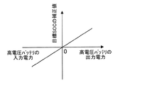
その後、制御装置19は、読込んだ情報に基づいて高電圧バッテリ13の入出力電力を算出する(S107)。ここで、高電圧バッテリ13の入力電力は、モータジェネレータ11、12からインバータ装置14を介して高電圧バッテリ13に供給される電力、及び、低電圧バッテリ17からコンバータ装置16を介して高電圧バッテリ13に供給される電力である。また、高電圧バッテリ13の出力電力は、高電圧バッテリ13からインバータ装置14を介してモータジェネレータ11、12に供給される電力、及び、高電圧バッテリ13から電動コンプレッサ装置15に供給される電力である。
Thereafter, the
そして、制御装置19は、予め設定されている高電圧バッテリ13の入出力電力と目標SOCの補正値の関係を示すマップと、算出した高電圧バッテリ13の入出力電力に基づいて目標SOCの補正値を求め、さらに目標SOCを補正する(S108)。ここで、高電圧バッテリ13の入出力電力と目標SOCの補正値の関係を示すマップは、高電圧バッテリ13の出力電力を正とした場合、図5に示すように、入力電力が大きくなるに従って目標SOCの補正値が小さくなり、出力電力が大きくなるに従って目標SOCの補正値が大きくなるように設定されている。なお、目標SOCの補正値は、目標SOCを補正しても、高電圧バッテリ13の温度がそれに対する閾値以上の場合における目標SOCより小さくなるように設定されている。
Then, the
その後、制御装置19は、読込んだ情報に基づいて予想されるモータジェネレータ11、12の回生動作によって発生する回生電力を算出する(S109)。具体的には、前述した車両の走行パターン指標に基づいて算出する。
Thereafter, the
そして、制御装置19は、予め設定されている回生電力と目標SOCの補正値の関係を示すマップと、算出した予想回生電力に基づいて目標SOCの補正値を求め、さらに目標SOCを補正する(S110)。ここで、回生電力と目標SOCの補正値の関係を示すマップは、図6に示すように、回生電力の値が大きくなるに従って目標SOCの補正値が減少するように設定されている。なお、目標SOCの補正値は、目標SOCを補正しても、高電圧バッテリ13の温度がそれに対する閾値以上の場合における目標SOCより小さくなるように設定されている。
Then, the
その後、制御装置19は、高電圧バッテリ13のSOCが補正した目標SOCになるようにエンジン10及びインバータ装置14を制御する(S111)。これにより、高電圧バッテリ13が充電され、高電圧バッテリ13のSOCが補正した目標SOCになる。そして、その後、制御装置19は高電圧バッテリ充電制御ルーチンを終了する。
Thereafter, the
次に、第1実施形態の車両制御システムの効果について説明する。 Next, the effect of the vehicle control system of the first embodiment will be described.
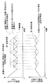
図7に示すように、高電圧バッテリ13のSOCがそれに対する下限閾値まで低下すると、高電圧バッテリ13に電力が供給され、高電圧バッテリ13が充電される。その結果、高電圧バッテリ13のSOCが上昇する。従来は、高電圧バッテリ13の温度に関係なく高電圧バッテリ13の目標SOCを一定値に設定していた。しかし、第1実施形態によれば、制御装置19は、図3に示すように、高電圧バッテリ13の温度がそれに対する閾値未満の場合には、高電圧バッテリ13の温度が閾値以上の場合に比べ、高電圧バッテリ13の目標SOCを小さくする。そのため、図7に示すように、高電圧バッテリ13の温度がそれに対する閾値未満の場合、従来のように目標SOCを一定に設定にする場合に比べ、高電圧バッテリ13のSOCの上昇が抑えられ、許容入力電力を大きくすることができる。従って、高電圧バッテリ13の温度低下に伴って最大入力電力が小さくなっても、高電圧バッテリ13の許容入力電力を充分に確保することができる。その結果、効率のよい条件でエンジン10を駆動し、高電圧バッテリ13を充電することができる。これにより、車両の燃費が悪化してしまうような事態を抑えることができる。
As shown in FIG. 7, when the SOC of the
高電圧バッテリ13の最大入力電力は、高電圧バッテリ13の温度によって変化する。第1実施形態によれば、制御装置19は、図3に示すように、高電圧バッテリ13の温度に基づいて高電圧バッテリ13の目標SOCを設定する。そのため、高電圧バッテリ13の温度に応じた目標SOCを適切に設定することができる。従って、高電圧バッテリ13の温度が低下しても、高電圧バッテリ13の許容入力電力を充分に確保することができる。
The maximum input power of the
高電圧バッテリ13の温度低下に伴って目標SOCを小さくすると、高電圧バッテリ13への電力の供給と停止が頻繁に繰り返されることになる。その結果、エンジン10の駆動と停止が頻繁に繰り返されることになり、車両の燃費が悪化してしまう可能性がある。しかし、第1実施形態によれば、制御装置19は、図4に示すように、車両の走行パターンに関する指標に基づいて設定した高電圧バッテリ13の目標SOCの補正値を求め、目標SOCを補正する。つまり、車両の走行パターンに関する指標に基づいて高電圧バッテリ13の目標SOCを設定する。高電圧バッテリ13に供給できる電力は、車両の走行パターンに応じて変化する。そのため、高電圧バッテリ13に供給できる電力に応じて目標SOCを適切に設定することができる。従って、エンジン10の駆動と停止が頻繁に繰り返され、車両の燃費が悪化するような事態を極力抑えることができる。
If the target SOC is reduced as the temperature of the
第1実施形態によれば、制御装置19は、車両の過去又は将来の走行パターンに関する指標に基づいて高電圧バッテリ13の目標SOCを設定する。そのため、高電圧バッテリ13に供給できる電力に応じて目標SOCを適切に設定することができる。
According to the first embodiment, the
第1実施形態によれば、車両の走行パターンに関する指標は、平均車両速度、平均車両駆動出力及び平均車両加減速度の少なくともいずれかである。そのため、高電圧バッテリ13に供給できる電力を確実に求めることができる。
According to the first embodiment, the index related to the travel pattern of the vehicle is at least one of an average vehicle speed, an average vehicle drive output, and an average vehicle acceleration / deceleration. Therefore, the power that can be supplied to the high-
高電圧バッテリ13の入力電力が大きい場合、目標SOCに達するまでの時間が早くなる。また、高電圧バッテリ13の出力電力が大きい場合、SOCの下限閾値に達するまでの時間が早くなる。そのため、高電圧バッテリ13への電力の供給と停止が頻繁に繰り返されることになる。その結果、エンジン10の駆動と停止が頻繁に繰り返されることになり、車両の燃費が悪化してしまう可能性がある。しかし、第1実施形態によれば、制御装置19は、図5に示すように、高電圧バッテリ13の入力電力及び出力電力に基づいて設定した高電圧バッテリ13の目標SOCの補正値を求め、目標SOCを補正する。つまり、高電圧バッテリ13の入力電力及び出力電力に基づいて高電圧バッテリ13の目標SOCを設定する。ここで、高電圧バッテリ13の入力電力は、モータジェネレータ11、12から高電圧バッテリ13に供給される電力、及び、低電圧バッテリ17から高電圧バッテリ13に供給される電力である。高電圧バッテリ13の出力電力は、高電圧バッテリ13からモータジェネレータ11、12に供給される電力、及び、高電圧バッテリ13から電動コンプレッサ装置15に供給される電力である。そのため、高電圧バッテリ13への電力の供給と停止が頻繁に繰り返されるような事態を極力抑えることができる。従って、エンジン10の駆動と停止が頻繁に繰り返され、車両の燃費が悪化するような事態を極力抑えることができる。
When the input power of the
モータジェネレータ11、12の回生動作によって発生する電力が大きい場合、目標SOCに達するまでの時間が早くなる。そのため、高電圧バッテリ13への電力の供給と停止が頻繁に繰り返されることになる。その結果、エンジン10の駆動と停止が頻繁に繰り返されることになり、車両の燃費が悪化してしまう可能性がある。しかし、第1実施形態によれば、制御装置19は、図6に示すように、モータジェネレータ11、12の回生動作によって発生する電力に基づいて設定した高電圧バッテリ13の目標SOCの補正値を求め、目標SOCを補正する。つまり、モータジェネレータ11、12の回生動作によって発生する電力に基づいて高電圧バッテリ13の目標SOCを設定する。そのため、高電圧バッテリ13への電力の供給と停止が頻繁に繰り返されるような事態を極力抑えることができる。従って、エンジン10の駆動と停止が頻繁に繰り返され、車両の燃費が悪化するような事態を極力抑えることができる。
When the electric power generated by the regenerative operation of
モータジェネレータ11、12の回生電力は、車両の駆動状態に応じて変化する。第1実施形態によれば、制御装置19は、車両の走行パターンに関する指標に基づいてモータジェネレータ11、12の回生動作によって発生する電力を求める。具体的には、車両の過去又は将来の走行パターンに関する指標に基づいて求める。ここで、車両の走行パターンに関する指標は、平均車両速度、平均車両駆動出力及び平均車両加減速度の少なくともいずれかである。そのため、モータジェネレータ11、12の回生電力を確実に求めることができる。
The regenerative power of
なお、第1実施形態では、車両制御システム1が、高電圧バッテリ13から電力を供給されることで動作する電気負荷として、電動コンプレッサ装置15を有している例を挙げているが、これに限られるものではない。車両制御システム1は、高電圧バッテリ13から電力を供給されることで動作する電気負荷として、ブロアファンや電気ヒータを有していてもよい。電動コンプレッサ、ブロアファン及び電気ヒータの少なくともいずれかを有していればよい。
In the first embodiment, an example in which the vehicle control system 1 includes the
また、第1実施形態では、低電圧バッテリ17からコンバータ装置16を介して高電圧バッテリ13に電力を供給できる例を挙げているが、これに限られるものではない。低電圧バッテリ17から高電圧バッテリ13に電力を供給できなくてもよい。この場合、高電圧バッテリ13の入力電力は、モータジェネレータ11、12からインバータ装置14を介して高電圧バッテリ13に供給される電力だけになる。
In the first embodiment, an example in which power can be supplied from the
1・・・車両制御システム、10・・・エンジン、11、12・・・モータジェネレータ、13・・・高電圧バッテリ(バッテリ)、14・・・インバータ装置(電力変換装置)、15・・・電動コンプレッサ装置(電気負荷)、16・・・コンバータ装置(電力供給源)、17・・・低電圧バッテリ(電力供給源)、18・・・補機、19・・・制御装置 DESCRIPTION OF SYMBOLS 1 ... Vehicle control system, 10 ... Engine, 11, 12 ... Motor generator, 13 ... High voltage battery (battery), 14 ... Inverter device (power converter device), 15 ... Electric compressor device (electric load), 16 ... converter device (power supply source), 17 ... low voltage battery (power supply source), 18 ... auxiliary equipment, 19 ... control device
Claims (12)
充放電可能なバッテリ(13)と、
前記バッテリから電力を供給されることで駆動力を発生し、前記エンジンから駆動力を供給されることで前記バッテリを充電するための電力を発生するモータジェネレータ(11、12)と、
前記バッテリから供給される電力を変換して前記モータジェネレータに供給することで前記モータジェネレータに駆動力を発生させ、前記モータジェネレータの発生した電力を変換して前記バッテリに供給することで前記バッテリを充電する電力変換装置(14)と、
前記エンジン及び前記電力変換装置を制御する制御装置(19)と、
を備え、前記バッテリの残存容量が下限閾値以下の場合、前記制御装置が、前記バッテリの残存容量が目標値になるように、前記エンジン及び前記電力変換装置を制御する車両制御システムにおいて、
前記制御装置は、前記バッテリの温度が閾値未満の場合には、前記バッテリの温度が閾値以上の場合に比べ、前記バッテリの残存容量の目標値を小さくすることを特徴とする車両制御システム。 An engine (10) mounted on a vehicle and generating a driving force by burning fuel;
A chargeable / dischargeable battery (13);
Motor generators (11, 12) that generate driving force by being supplied with electric power from the battery, and generate electric power for charging the battery by being supplied with driving force from the engine;
The power supplied from the battery is converted and supplied to the motor generator to generate a driving force in the motor generator, and the electric power generated by the motor generator is converted and supplied to the battery. A power converter (14) for charging;
A control device (19) for controlling the engine and the power converter;
And when the remaining capacity of the battery is equal to or lower than a lower threshold, the control device controls the engine and the power converter so that the remaining capacity of the battery becomes a target value.
When the temperature of the battery is lower than the threshold, the control device reduces the target value of the remaining capacity of the battery as compared with the case where the temperature of the battery is equal to or higher than the threshold.
前記バッテリの入力電力は、前記モータジェネレータから前記バッテリに供給される電力、及び、前記電力供給源から前記バッテリに供給される電力であることを特徴とする請求項5に記載の車両制御システム。 A power supply source (16, 17) for supplying power to the battery;
The vehicle control system according to claim 5, wherein the input power of the battery is power supplied from the motor generator to the battery and power supplied from the power supply source to the battery.
前記バッテリの出力電力は、前記バッテリから前記モータジェネレータに供給される電力、及び、前記バッテリから前記電気負荷に供給される電力であることを特徴とする請求項5又は6に記載の車両制御システム。 An electric load (15) that operates by being supplied with electric power from the battery;
The vehicle control system according to claim 5 or 6, wherein the output power of the battery is power supplied from the battery to the motor generator and power supplied from the battery to the electric load. .
Priority Applications (2)
| Application Number | Priority Date | Filing Date | Title |
|---|---|---|---|
| JP2014081005A JP2015199470A (en) | 2014-04-10 | 2014-04-10 | vehicle control system |
| US14/681,253 US9895994B2 (en) | 2014-04-10 | 2015-04-08 | Vehicle control system |
Applications Claiming Priority (1)
| Application Number | Priority Date | Filing Date | Title |
|---|---|---|---|
| JP2014081005A JP2015199470A (en) | 2014-04-10 | 2014-04-10 | vehicle control system |
Publications (1)
| Publication Number | Publication Date |
|---|---|
| JP2015199470A true JP2015199470A (en) | 2015-11-12 |
Family
ID=54264397
Family Applications (1)
| Application Number | Title | Priority Date | Filing Date |
|---|---|---|---|
| JP2014081005A Pending JP2015199470A (en) | 2014-04-10 | 2014-04-10 | vehicle control system |
Country Status (2)
| Country | Link |
|---|---|
| US (1) | US9895994B2 (en) |
| JP (1) | JP2015199470A (en) |
Cited By (2)
| Publication number | Priority date | Publication date | Assignee | Title |
|---|---|---|---|---|
| JP2018074812A (en) * | 2016-10-31 | 2018-05-10 | 株式会社東芝 | Vehicle control device and charge target determination method |
| US10351011B2 (en) | 2017-01-17 | 2019-07-16 | Toyota Jidosha Kabushiki Kaisha | Electric vehicle |
Families Citing this family (10)
| Publication number | Priority date | Publication date | Assignee | Title |
|---|---|---|---|---|
| DE102014218738A1 (en) * | 2014-09-18 | 2016-03-24 | Continental Automotive Gmbh | Electrical system for an electrically driven vehicle |
| JP6237708B2 (en) * | 2015-06-11 | 2017-11-29 | トヨタ自動車株式会社 | Vehicle control device |
| FR3060889B1 (en) * | 2016-12-21 | 2020-12-04 | Commissariat Energie Atomique | METHOD AND DEVICE FOR CHARGING A BATTERY |
| US11453382B2 (en) * | 2017-05-01 | 2022-09-27 | Cummins Inc. | Systems and methods for controlling energy generation in a hybrid powertrain |
| JP6874702B2 (en) * | 2018-01-29 | 2021-05-19 | トヨタ自動車株式会社 | Hybrid vehicle |
| JP6939606B2 (en) * | 2018-01-29 | 2021-09-22 | トヨタ自動車株式会社 | Hybrid vehicle |
| US11167745B2 (en) * | 2018-04-19 | 2021-11-09 | Toyota Jidosha Kabushiki Kaisha | Control system of hybrid vehicle |
| CN109494854A (en) * | 2018-12-05 | 2019-03-19 | 合肥同智机电控制技术有限公司 | A kind of vehicle-mounted power taking driving power generation battery charging system and control method |
| CN110816307A (en) * | 2019-11-20 | 2020-02-21 | 太原科技大学 | Hydrogen fuel turbine range extender system for electric automobile and control method |
| JP7306415B2 (en) * | 2021-02-15 | 2023-07-11 | トヨタ自動車株式会社 | vehicle controller |
Family Cites Families (6)
| Publication number | Priority date | Publication date | Assignee | Title |
|---|---|---|---|---|
| JP3573206B2 (en) * | 2002-03-12 | 2004-10-06 | トヨタ自動車株式会社 | Vehicle control device |
| JP5089883B2 (en) * | 2005-12-16 | 2012-12-05 | 日立ビークルエナジー株式会社 | Battery management device |
| JP4183013B1 (en) | 2007-05-15 | 2008-11-19 | トヨタ自動車株式会社 | Vehicle and control method thereof |
| JP5051794B2 (en) * | 2009-12-17 | 2012-10-17 | トヨタ自動車株式会社 | Charger |
| JP5879768B2 (en) | 2011-06-22 | 2016-03-08 | トヨタ自動車株式会社 | Hybrid vehicle |
| US20130015814A1 (en) * | 2011-07-13 | 2013-01-17 | Tesla Motors, Inc. | Charge Disruption Monitoring and Notification System |
-
2014
- 2014-04-10 JP JP2014081005A patent/JP2015199470A/en active Pending
-
2015
- 2015-04-08 US US14/681,253 patent/US9895994B2/en active Active
Cited By (2)
| Publication number | Priority date | Publication date | Assignee | Title |
|---|---|---|---|---|
| JP2018074812A (en) * | 2016-10-31 | 2018-05-10 | 株式会社東芝 | Vehicle control device and charge target determination method |
| US10351011B2 (en) | 2017-01-17 | 2019-07-16 | Toyota Jidosha Kabushiki Kaisha | Electric vehicle |
Also Published As
| Publication number | Publication date |
|---|---|
| US20150291051A1 (en) | 2015-10-15 |
| US9895994B2 (en) | 2018-02-20 |
Similar Documents
| Publication | Publication Date | Title |
|---|---|---|
| JP2015199470A (en) | vehicle control system | |
| JP4793237B2 (en) | Secondary battery charge / discharge control device and vehicle equipped with the same | |
| JP5382238B2 (en) | Hybrid vehicle and control method thereof | |
| US11097624B2 (en) | Driving system | |
| EP2918442B1 (en) | Charge/discharge system | |
| JP5454789B2 (en) | Control device for electric vehicle | |
| JP6274386B2 (en) | Hybrid vehicle engine operation control device | |
| EP2851229B1 (en) | Control device for hybrid vehicle and control method for hybrid vehicle | |
| JP2009027774A (en) | Vehicle | |
| US9834100B2 (en) | Charge/discharge system | |
| JP6768813B2 (en) | vehicle | |
| JP2009201170A (en) | Charge control system | |
| JP2019119392A (en) | Control device of hybrid system in vehicle | |
| JP5344090B2 (en) | Vehicle regeneration control system | |
| JP2013133061A (en) | Hybrid vehicle | |
| JP2013133062A (en) | Hybrid vehicle | |
| JP2013133060A (en) | Hybrid vehicle | |
| WO2016132580A1 (en) | Charging and discharging control device, mobile body, and electric power allocation amount determining method | |
| JP2013097961A (en) | Temperature control device for battery and vehicle | |
| JP2012044805A (en) | Vehicular power supply system | |
| JP2011239629A (en) | Control device for electric vehicle | |
| JP6470947B2 (en) | Drive system and diesel car | |
| JP2015080328A (en) | Electric vehicle power supply system | |
| JP5879768B2 (en) | Hybrid vehicle | |
| JP2020102926A (en) | Battery temperature adjusting device for vehicle |