JP2014502545A - Method and apparatus for decoction of material in a solvent - Google Patents
Method and apparatus for decoction of material in a solvent Download PDFInfo
- Publication number
- JP2014502545A JP2014502545A JP2013546796A JP2013546796A JP2014502545A JP 2014502545 A JP2014502545 A JP 2014502545A JP 2013546796 A JP2013546796 A JP 2013546796A JP 2013546796 A JP2013546796 A JP 2013546796A JP 2014502545 A JP2014502545 A JP 2014502545A
- Authority
- JP
- Japan
- Prior art keywords
- container
- solvent
- pipe
- outlet
- inlet
- Prior art date
- Legal status (The legal status is an assumption and is not a legal conclusion. Google has not performed a legal analysis and makes no representation as to the accuracy of the status listed.)
- Ceased
Links
Images


Classifications
-
- A—HUMAN NECESSITIES
- A47—FURNITURE; DOMESTIC ARTICLES OR APPLIANCES; COFFEE MILLS; SPICE MILLS; SUCTION CLEANERS IN GENERAL
- A47J—KITCHEN EQUIPMENT; COFFEE MILLS; SPICE MILLS; APPARATUS FOR MAKING BEVERAGES
- A47J31/00—Apparatus for making beverages
- A47J31/002—Apparatus for making beverages following a specific operational sequence, e.g. for improving the taste of the extraction product
-
- A—HUMAN NECESSITIES
- A23—FOODS OR FOODSTUFFS; TREATMENT THEREOF, NOT COVERED BY OTHER CLASSES
- A23F—COFFEE; TEA; THEIR SUBSTITUTES; MANUFACTURE, PREPARATION, OR INFUSION THEREOF
- A23F3/00—Tea; Tea substitutes; Preparations thereof
- A23F3/16—Tea extraction; Tea extracts; Treating tea extract; Making instant tea
- A23F3/18—Extraction of water soluble tea constituents
-
- A—HUMAN NECESSITIES
- A23—FOODS OR FOODSTUFFS; TREATMENT THEREOF, NOT COVERED BY OTHER CLASSES
- A23F—COFFEE; TEA; THEIR SUBSTITUTES; MANUFACTURE, PREPARATION, OR INFUSION THEREOF
- A23F3/00—Tea; Tea substitutes; Preparations thereof
- A23F3/16—Tea extraction; Tea extracts; Treating tea extract; Making instant tea
- A23F3/22—Drying or concentrating tea extract
- A23F3/24—Drying or concentrating tea extract by freezing out the water
-
- A—HUMAN NECESSITIES
- A23—FOODS OR FOODSTUFFS; TREATMENT THEREOF, NOT COVERED BY OTHER CLASSES
- A23F—COFFEE; TEA; THEIR SUBSTITUTES; MANUFACTURE, PREPARATION, OR INFUSION THEREOF
- A23F5/00—Coffee; Coffee substitutes; Preparations thereof
- A23F5/20—Reducing or removing alkaloid content; Preparations produced thereby; Extracts or infusions thereof
- A23F5/206—Reducing or removing alkaloid content; Preparations produced thereby; Extracts or infusions thereof by extraction of the beans with selective solvents other than water or aqueous bean extracts, including supercritical gases
-
- A—HUMAN NECESSITIES
- A23—FOODS OR FOODSTUFFS; TREATMENT THEREOF, NOT COVERED BY OTHER CLASSES
- A23F—COFFEE; TEA; THEIR SUBSTITUTES; MANUFACTURE, PREPARATION, OR INFUSION THEREOF
- A23F5/00—Coffee; Coffee substitutes; Preparations thereof
- A23F5/24—Extraction of coffee; Coffee extracts; Making instant coffee
- A23F5/26—Extraction of water-soluble constituents
- A23F5/262—Extraction of water-soluble constituents the extraction liquid flows through a stationary bed of solid substances, e.g. in percolation columns
-
- A—HUMAN NECESSITIES
- A23—FOODS OR FOODSTUFFS; TREATMENT THEREOF, NOT COVERED BY OTHER CLASSES
- A23F—COFFEE; TEA; THEIR SUBSTITUTES; MANUFACTURE, PREPARATION, OR INFUSION THEREOF
- A23F5/00—Coffee; Coffee substitutes; Preparations thereof
- A23F5/44—Coffee substitutes
-
- A—HUMAN NECESSITIES
- A23—FOODS OR FOODSTUFFS; TREATMENT THEREOF, NOT COVERED BY OTHER CLASSES
- A23F—COFFEE; TEA; THEIR SUBSTITUTES; MANUFACTURE, PREPARATION, OR INFUSION THEREOF
- A23F5/00—Coffee; Coffee substitutes; Preparations thereof
- A23F5/46—Coffee flavour; Coffee oil; Flavouring of coffee or coffee extract
- A23F5/48—Isolation or recuperation of coffee flavour or coffee oil
- A23F5/483—Isolation or recuperation of coffee flavour or coffee oil by solvent extraction of the beans, ground or not
-
- A—HUMAN NECESSITIES
- A23—FOODS OR FOODSTUFFS; TREATMENT THEREOF, NOT COVERED BY OTHER CLASSES
- A23L—FOODS, FOODSTUFFS, OR NON-ALCOHOLIC BEVERAGES, NOT COVERED BY SUBCLASSES A21D OR A23B-A23J; THEIR PREPARATION OR TREATMENT, e.g. COOKING, MODIFICATION OF NUTRITIVE QUALITIES, PHYSICAL TREATMENT; PRESERVATION OF FOODS OR FOODSTUFFS, IN GENERAL
- A23L27/00—Spices; Flavouring agents or condiments; Artificial sweetening agents; Table salts; Dietetic salt substitutes; Preparation or treatment thereof
- A23L27/10—Natural spices, flavouring agents or condiments; Extracts thereof
- A23L27/11—Natural spices, flavouring agents or condiments; Extracts thereof obtained by solvent extraction
-
- A—HUMAN NECESSITIES
- A23—FOODS OR FOODSTUFFS; TREATMENT THEREOF, NOT COVERED BY OTHER CLASSES
- A23L—FOODS, FOODSTUFFS, OR NON-ALCOHOLIC BEVERAGES, NOT COVERED BY SUBCLASSES A21D OR A23B-A23J; THEIR PREPARATION OR TREATMENT, e.g. COOKING, MODIFICATION OF NUTRITIVE QUALITIES, PHYSICAL TREATMENT; PRESERVATION OF FOODS OR FOODSTUFFS, IN GENERAL
- A23L33/00—Modifying nutritive qualities of foods; Dietetic products; Preparation or treatment thereof
- A23L33/10—Modifying nutritive qualities of foods; Dietetic products; Preparation or treatment thereof using additives
- A23L33/105—Plant extracts, their artificial duplicates or their derivatives
-
- A—HUMAN NECESSITIES
- A47—FURNITURE; DOMESTIC ARTICLES OR APPLIANCES; COFFEE MILLS; SPICE MILLS; SUCTION CLEANERS IN GENERAL
- A47J—KITCHEN EQUIPMENT; COFFEE MILLS; SPICE MILLS; APPARATUS FOR MAKING BEVERAGES
- A47J31/00—Apparatus for making beverages
-
- A—HUMAN NECESSITIES
- A47—FURNITURE; DOMESTIC ARTICLES OR APPLIANCES; COFFEE MILLS; SPICE MILLS; SUCTION CLEANERS IN GENERAL
- A47J—KITCHEN EQUIPMENT; COFFEE MILLS; SPICE MILLS; APPARATUS FOR MAKING BEVERAGES
- A47J31/00—Apparatus for making beverages
- A47J31/04—Coffee-making apparatus with rising pipes
- A47J31/053—Coffee-making apparatus with rising pipes with repeated circulation of the extract through the filter
-
- A—HUMAN NECESSITIES
- A47—FURNITURE; DOMESTIC ARTICLES OR APPLIANCES; COFFEE MILLS; SPICE MILLS; SUCTION CLEANERS IN GENERAL
- A47J—KITCHEN EQUIPMENT; COFFEE MILLS; SPICE MILLS; APPARATUS FOR MAKING BEVERAGES
- A47J31/00—Apparatus for making beverages
- A47J31/18—Apparatus in which ground coffee or tea-leaves are immersed in the hot liquid in the beverage container
-
- B—PERFORMING OPERATIONS; TRANSPORTING
- B01—PHYSICAL OR CHEMICAL PROCESSES OR APPARATUS IN GENERAL
- B01D—SEPARATION
- B01D11/00—Solvent extraction
- B01D11/02—Solvent extraction of solids
- B01D11/0215—Solid material in other stationary receptacles
-
- B—PERFORMING OPERATIONS; TRANSPORTING
- B01—PHYSICAL OR CHEMICAL PROCESSES OR APPARATUS IN GENERAL
- B01D—SEPARATION
- B01D11/00—Solvent extraction
- B01D11/02—Solvent extraction of solids
- B01D11/0215—Solid material in other stationary receptacles
- B01D11/0219—Fixed bed of solid material
-
- B—PERFORMING OPERATIONS; TRANSPORTING
- B01—PHYSICAL OR CHEMICAL PROCESSES OR APPARATUS IN GENERAL
- B01D—SEPARATION
- B01D11/00—Solvent extraction
- B01D11/02—Solvent extraction of solids
- B01D11/0261—Solvent extraction of solids comprising vibrating mechanisms, e.g. mechanical, acoustical
- B01D11/0265—Applying ultrasound
Landscapes
- Engineering & Computer Science (AREA)
- Food Science & Technology (AREA)
- Chemical & Material Sciences (AREA)
- Life Sciences & Earth Sciences (AREA)
- Polymers & Plastics (AREA)
- Health & Medical Sciences (AREA)
- Nutrition Science (AREA)
- Chemical Kinetics & Catalysis (AREA)
- Physics & Mathematics (AREA)
- Acoustics & Sound (AREA)
- Mycology (AREA)
- Botany (AREA)
- Oil, Petroleum & Natural Gas (AREA)
- Mechanical Engineering (AREA)
- Extraction Or Liquid Replacement (AREA)
- General Health & Medical Sciences (AREA)
- Birds (AREA)
- Epidemiology (AREA)
- Animal Behavior & Ethology (AREA)
- Microbiology (AREA)
- Public Health (AREA)
- Veterinary Medicine (AREA)
- Biotechnology (AREA)
- Apparatus For Making Beverages (AREA)
- Tea And Coffee (AREA)
- Physical Or Chemical Processes And Apparatus (AREA)
- Fluid-Pressure Circuits (AREA)
Abstract
本発明は、溶媒(3)中に材料(2)を煎じるための装置(1)であり、前記装置は:
・前記溶媒を含む第1の容器(4);前記第1の容器の入口(I1)と前記第1の容器の出口(O1)を接続するパイプ(5)、前記溶媒を前記出口(O1)から前記入口(I1)へ循環させるための前記パイプに直列に設けられるポンプ(6)、前記材料を含む第2の容器を含み、前記第2の容器(7)が、前記パイプと直列して設けられ、前記パイプ内を循環する溶媒が前記材料間で循環することができ、前記第2の容器に隣接して設けられる波発生装置(8)を含み、前記材料に向かって波(FW)を発生させる、を含む。前記材料に向けた波場を適用することと組合せて、前記溶媒の動的循環は、前記材料中の化合物の抽出を促進し、改善された抽出効率を達成することができる。The present invention is an apparatus (1) for decocting material (2) in solvent (3), said apparatus:
A first container (4) containing the solvent; a pipe (5) connecting the inlet (I1) of the first container and the outlet (O1) of the first container; and the solvent to the outlet (O1) A pump (6) provided in series with the pipe for circulation to the inlet (I1), a second container containing the material, the second container (7) in series with the pipe A wave generator (8) is provided and can be circulated between the materials and circulated between the pipes and is provided adjacent to the second container, wherein the waves (FW) toward the material Generating. In combination with applying a wave field directed at the material, the dynamic circulation of the solvent can facilitate the extraction of the compounds in the material and achieve improved extraction efficiency.
Description
本発明は材料を溶媒中で煎じる方法及び装置に関する。本発明は、ドリンク又は飲料を製造する分野で使用可能である。 The present invention relates to a method and apparatus for decocting a material in a solvent. The present invention can be used in the field of producing drinks or beverages.
(源)材料を溶媒中で煎じることで飲料を製造することは、種々の飲料又は中国の伝統的医用飲料を製造するためにしばしば使用されている。例えば、伝統的中国医薬は、ハーブ/植物を材料として、溶媒としての熱/沸騰水中で、材料に含まれる固体/化合物(すなわち活性栄養成分)が溶媒中に抽出/拡散されるまで煎じることで製造される。所定の時間後、材料を前記溶媒から取り出して得られる飲料は直ぐに飲むことができる。伝統的に、この工程は次のステップを含む:
・材料を準備すること:サイズを整える(例えば切断又は粉砕)、材料を洗浄すること。材料は又粉末状であり得る。
・浸漬させること:前記材料を冷水中にある時間漬ける。このステップの目的は、水を前記材料の細胞構造中に侵入させて前記溶媒で抽出が容易になるようにすることである。
・煎じること:材料を沸騰水を含む受容器内に置き、前記水中の材料から化合物を抽出する。
・濾過すること:前記材料を溶媒から分離し、ユーザーが残渣のないきれいな飲料を消費することができる。
Making beverages by decocting the (source) material in a solvent is often used to make various beverages or traditional Chinese medical beverages. For example, traditional Chinese medicine uses herbs / plants as ingredients, decocting heat / boiling water as solvent until the solids / compounds (ie active nutrients) contained in the material are extracted / spread into the solvent. Manufactured. After a predetermined time, the beverage obtained by removing the material from the solvent can be drunk immediately. Traditionally, this process involves the following steps:
Preparing the material: cleaning the material, sizing (eg cutting or grinding). The material can also be in powder form.
-Soaking: Soak the material in cold water for a period of time. The purpose of this step is to allow water to penetrate into the cellular structure of the material to facilitate extraction with the solvent.
Infusion: Place the material in a receiver containing boiling water and extract the compound from the material in the water.
Filtering: The material is separated from the solvent, allowing the user to consume a clean beverage with no residue.
しかし、かかる工程は、ユーザーにとって簡便ではない、というのはこの工程は連続的に多くのステップを必要とするからであり、また抽出に数時間を要するからであり、即ち飲料が準備できるようになるまでに相当な時間がかかるからである。この工程を迅速化するために、ユーザーは煎じる時間を短縮しようとするが、こうすると全ての栄養物が材料から抽出されない恐れがあり、その結果飲料に含まれる固体/化合物に関して最適ではない飲料となる可能性があり、これはユーザーへの味又は健康についての有効性に影響を与えるおそれがある。 However, such a process is not convenient for the user, because this process requires many steps in a row and because it takes several hours to extract, i.e. the beverage can be prepared. This is because it takes a considerable amount of time. To speed up this process, the user tries to reduce the time to brew, but this may not extract all the nutrients from the ingredients, resulting in a non-optimal beverage with respect to the solids / compounds contained in the beverage. This may affect the user's taste or health effectiveness.
本発明の課題は、材料を溶媒中に煎じる改善された方法及び装置を提供することである。 It is an object of the present invention to provide an improved method and apparatus for decocting material in a solvent.
この課題を解決するために、本発明の装置は:
・前記溶媒を含む第1の容器;
・前記第1の容器の入口と前記第1の容器の出口を接続するパイプ、
・前記溶媒を前記出口から前記入口へ循環させるための前記パイプに直列に設けられるポンプ、
・前記材料を含む第2の容器を含み、前記第2の容器が、前記パイプと直列して設けられ、前記パイプ内を循環する溶媒が前記材料間で循環することができ、
・前記第2の容器に隣接して設けられる波発生装置を含み、前記材料に向かって波を発生させる、を含む。
To solve this problem, the device of the present invention:
A first container containing the solvent;
A pipe connecting the inlet of the first container and the outlet of the first container;
A pump provided in series with the pipe for circulating the solvent from the outlet to the inlet;
Including a second container containing the material, wherein the second container is provided in series with the pipe, and a solvent circulating in the pipe can be circulated between the materials;
-Including a wave generating device provided adjacent to the second container, and generating a wave toward the material.
前記溶媒が前記受容器内で静的であり、前記材料の周囲で迅速に飽和する傾向があり、これにより前記材料に含まれる化合物の抽出が遅くなる従来の煎じる工程と比較して、本発明による装置は、前記材料間の溶媒の循環を可能にし、材料の周囲に存在する溶媒を連続的に交換させ、及び低濃度の化合物を含む新たな溶媒により、抽出化合物の濃度が高まる(すなわち飽和する)こととなる。従って、これは材料中の化合物の抽出を促進し、飲料製造の全時間を短縮する。前記波発生装置による波の場は、分極効果により前記材料内の細胞膜中にポア(孔)を生じさせ、及び/又はキャビテーション効果によりこれらの細胞壁を破壊し得る。波の場は従って、前記材料の内部で前記化合物の抽出効率の増加に寄与し、このことはかかる装置を用いることで従来技術での材料の浸漬は必要なくなる。本発明を用いると、前記溶媒の動的循環は、前記材料に向けた波の場の適用と組合せて、前記材料中の化合物の抽出を促進させ、改善された抽出効率を可能とする。 Compared to the conventional decocting process, the solvent is static in the receptor and tends to saturate rapidly around the material, thereby slowing the extraction of the compounds contained in the material. According to the apparatus allows the circulation of the solvent between the materials, continuously exchanges the solvent present around the material, and the concentration of the extracted compound is increased by a new solvent containing a low concentration of compound (ie saturation). Will be). This therefore facilitates the extraction of the compounds in the material and reduces the overall time of beverage production. The wave field generated by the wave generator can cause pores in the cell membrane within the material due to polarization effects and / or destroy these cell walls due to cavitation effects. The wave field thus contributes to an increase in the extraction efficiency of the compound within the material, which eliminates the need for material immersion in the prior art using such an apparatus. With the present invention, the dynamic circulation of the solvent, in combination with the application of a wave field directed at the material, facilitates the extraction of compounds in the material, allowing improved extraction efficiency.
本発明はまた、本発明の装置により実施される種々のステップを含む方法に関する。 The invention also relates to a method comprising various steps carried out by the device of the invention.
以下、本発明の他の側面及び詳細な説明が与えられる。 Other aspects and detailed descriptions of the present invention are given below.
本発明の具体的な側面は、以下実施態様に基づき、添付の図面を参照しつつ説明される。図面中では同じ要素には同じ符号で示される。 Specific aspects of the present invention will be described below based on embodiments with reference to the accompanying drawings. In the drawings, the same elements are denoted by the same reference numerals.
図1は、溶媒3中に材料2を煎じるための本発明による装置1の第1の実施態様を示す。前記装置は:
・前記溶媒を含む第の容器4、
・前記第1の容器の入口11へ前記第1の容器の出口O1を接続するパイプ5、
・前記出O1から前記入口I1へ循環させるための前記パイプと直列に設けられるポンプ6、
・前記材料を含むための第2の容器7を含み、前記第2の容器は前記パイプに直列に設けられ、前記パイプ内を循環する前記溶媒が前記材料内を循環することを可能にし、
・前記材料に向けて波の場FWを発生するための前記第2の容器に隣接して設けられる波発生装置8を含む。
FIG. 1 shows a first embodiment of an
A
A
A pump 6 provided in series with the pipe for circulation from the outlet O1 to the inlet I1;
Including a second container 7 for containing the material, the second container being provided in series with the pipe, allowing the solvent circulating in the pipe to circulate in the material;
A wave generator 8 provided adjacent to the second container for generating a wave field FW towards the material;
材料は、例えば茶葉、植物、葉、コーヒー豆、ハーブ、植物根、果実又はこれらの材料の組合せであり得る。前記溶媒は、例えば水、ミネラルウオーター、水道水、塩水、アルコール又はこれらの溶媒の混合物であり得る。 The material can be, for example, tea leaves, plants, leaves, coffee beans, herbs, plant roots, fruits or combinations of these materials. The solvent can be, for example, water, mineral water, tap water, salt water, alcohol, or a mixture of these solvents.
前記容器4は、前記煎じる工程を開始する際にユーザーにより前記溶媒3が注ぎ込まれるタンクである。説明のために、前記溶媒は、複数の点線で表されている。
The
前記パイプは前記溶媒の外側に設けられる。
例えば、プラスチック又はガラスなどの材料から形成されたパイプが使用され得る。前記パイプ5の第1の部分は前記第1の容器の出口O1から出て、前記第2の容器の入口I2へ接続される。前記溶媒が前記第2の容器に入ると、それは前記材料を通過し、これらの材料中の化合物の中抽出を容易にする。
The pipe is provided outside the solvent.
For example, pipes formed from materials such as plastic or glass can be used. The first part of the
前記パイプ5の第2の部分は、前記第2の容器の出口O2から出て、前記ポンプ6の前記入口へ接続される。前記ポンプ6は、前記第1の容器の外部で前記溶媒の閉鎖循環を作るために使用され、溶媒の循環の方向は図1の短い矢印で示されている。全てのタイプのポンプが使用され、例えば電気水ポンプであり得る。好ましくは、前記ポンプの流速は、1分間当たり数リットルの程度である。好ましくは、溶媒の容積が多くなるほど、流速は増加される。前記パイプ5の第3部分は前記ポンプの出口から出て、前記第1の容器の入口I1へ接続される。前記第1の容器に入り、かつ前記材料から抽出された化合物のより高濃度を持つ前記溶媒は、前記第1の容器内に既に存在する新鮮な溶媒、即ちより低濃度の化合物を含む溶媒と混合される。次に前記第1の溶媒は、前記パイプ5の前記第1の部分へ出ていく。
The second part of the
前記第1の容器の前記出口O1及び入口I1は、異なる位置に設けられ得る:
・図1に示されるように、前記第1の容器の出口O1は、前記第1の容器の壁の底部に設けられ、及び前記入口I1は前記第1の容器の底部に設けられ、
・図9Aに示されるように、前記出口O1及び入口I1はそれぞれ、前記第1の容器の壁の底部に、例えばお互いに対抗して設けられ、
・図9Bに示されるように、前記出口O1及び入口I1はそれぞれ、前記第1の容器の壁の中間部に、例えばお互いに対抗して設けられ、
・図9Cに示されるように、前記出口O1は前記第1の容器に上部に設けられ、かつ入口I1はそれぞれ、前記第1の容器の底部に設けられ、
・図9Dに示されるように、前記出O1及び入口I1は前記第1の容器に底部に設けられる。
The outlet O1 and inlet I1 of the first container may be provided at different positions:
As shown in FIG. 1, the outlet O1 of the first container is provided at the bottom of the wall of the first container, and the inlet I1 is provided at the bottom of the first container,
As shown in FIG. 9A, the outlet O1 and the inlet I1 are each provided at the bottom of the wall of the first container, for example, facing each other,
As shown in FIG. 9B, the outlet O1 and the inlet I1 are each provided in the middle part of the wall of the first container, for example, facing each other,
9C, the outlet O1 is provided at the top of the first container, and the inlets I1 are each provided at the bottom of the first container,
As shown in FIG. 9D, the outlet O1 and the inlet I1 are provided at the bottom of the first container.
留意すべきことは、前記出口O1及び入口I1の位置は、前記入口I1に入る前記溶媒が、出口O1を通って前記第1の容器を出る前に前記第1の容器内に既に存在する溶媒と十分混合される限り、考えられ得る、ということである。 It should be noted that the location of the outlet O1 and the inlet I1 is such that the solvent entering the inlet I1 is already present in the first container before exiting the first container through the outlet O1. As long as it is well mixed with.
前記第2の容器から流れ出た高濃度の化合物を含む前記溶媒が、低濃度の化合物を含む前記第1の容器内のより大きい容積の溶媒により希釈され得ることを保証するために、前記第1の容器の容積は、前記第2の容器の容積よりも大きく、好ましくは最大数百倍大きい。 To ensure that the solvent containing a high concentration of compound flowing out of the second container can be diluted with a larger volume of solvent in the first container containing a low concentration of compound, the first The volume of the container is larger than the volume of the second container, preferably a maximum of several hundred times.
前記第2の容器に隣接して設けられる波発生装置8は、前記材料に向かって波の場FWを生成することを目的とする。この波の場は、分極効果により前記材料の細胞膜に孔(ポア)を生じさせ、及び/又はキャビテーション効果で細胞壁を破壊する。これにより、前記材料の内部の化合物をより容易に抽出することを可能にする。前記溶媒が前記材料の周りを循環する(即ち溶媒が動的であり静的ではない)ことを考慮すると、比較的低い強度の波場が使用可能である。 The wave generator 8 provided adjacent to the second container aims to generate a wave field FW toward the material. This wave field creates pores in the cell membrane of the material due to the polarization effect and / or destroys the cell wall due to the cavitation effect. This makes it possible to extract compounds inside the material more easily. Considering that the solvent circulates around the material (ie, the solvent is dynamic and not static), a relatively low intensity wave field can be used.
溶媒に循環と波場の適用の工程は、所定の時間、例えば前記溶媒中の化合物の濃度や前記溶媒の味見により殆どの化合物が材料から抽出されると分かるまで、続けられる。留意すべきことは、この時間は使用される材料に依存して変更され得るということであり、これはこの側面をさらに詳細に説明することは本発明の目的ではない、ということである。 The process of cycling and applying the wave field to the solvent is continued for a predetermined time, eg, until it is found that most of the compound is extracted from the material by concentration of the compound in the solvent and taste of the solvent. It should be noted that this time can be varied depending on the material used, which is not the purpose of the present invention to describe this aspect in more detail.
図2は、溶媒3中に材料2を煎じるための本発明による装置1の第2の実施態様の部分を示す。図1に示された装置に含まれる要素に加えて、この波発生装置8は、超音波場を発生させるための超音波プローブ9を含む。超音波の場は矢印FW1で示される。前記超音波プローブは、前記第2の容器に壁に隣接して設けられ、超音波が前記第1の容器を進行することを可能にし、これは所謂超音波浴又は超音波洗浄装置での波伝播と類似する。例えば、前記超音波プローブは圧電材料トランスデューサに対応し、周波数範囲が[20kHz;400kHz]の超音波を生成するための外部制御装置(図示されていない)に接続されている。超音波の場は、キャビテーション効果により材料中の細胞壁を破壊することを可能にする。又は(図示されていない)、前記超音波プローブは前記第2の容器に隣接されるのではなく、前記第2の容器に空間内部に直接設けられ、前記空間で循環する溶媒内に触れることとなる。
FIG. 2 shows part of a second embodiment of the
図3は、溶媒3に材料2を煎じるための、本発明による装置1の第3の実施態様の部分を示す。図2に示された装置に含まれる要素に加えて、前記超音波プローブ9は、前記第2の容器7の周りに設けられる。前記超音波プローブは、前記第2の容器の壁に隣接して設けられ、超音波が前記第1の容器を進行することを可能にし、これは所謂超音波浴又は超音波洗浄装置での波伝播と類似する。前記第2の容器の周りに複数のプローブを設けることで、多重の波場が生成され、2つのプローブが使用される場合には、超音波の第1の場FW1a及び超音波の第2の場FW1bが発生する。これにより、前記材料への異なる方向に超音波の場を供することが可能となり、キャビテーション効果による前記材料の細胞壁の破壊を最大化することを可能にする。
FIG. 3 shows part of a third embodiment of the
図4は、溶媒3に材料2を煎じるための、本発明による装置1の第4の実施態様の部分を示す。図1に示された装置に含まれる要素に加えて、前記超音波プローブ8は、パルス電波FW2の場を発生させるための1対の電極10を含む。前記電極は、プレートに対応し、例えばステンレス鋼から形成され、外部制御装置(図示されていない)により与えられる電圧が供給される。第1の電圧が第1の電極に与えられ、第2の電圧が第2の電極に与えられると、この電圧差により前記電極間に電場が形成される。好ましくは、前記電場は、周波数範囲が[1Hz;100Hz]を持ち、電場勾配の範囲が[1kV/cm:100kV/cm]であり、パルス間隔は数マイクロ秒の範囲である。パルス電波の場は、材料の膜内にポアを形成し、及び/又は前記分極効果による材料の膜孔を開口/拡大させる。又は(図示されていない)、前記電極は前記第2の容器の壁の外部に設けられずに、前記第2の容器の空間内部に直接設けられる。
FIG. 4 shows part of a fourth embodiment of the
好ましくは前記電極10は前記第2の容器7の周りに設けられる。前記第2の容器に周りに複数の電極対を設けることで、波の多重場が発生される。これにより、前記材料の異なる方向に向けて電波の場を与えることができ、材料中の膜のポアの形成を最大化し、及び/又は分極効果による材料の膜の開口及び/又は拡大を可能にする。例えば、前記第2の容器が立方体形状である場合、3組の電極が使用でき、それぞれの対は所定の側に置かれる電極と、対抗する側に置かれた第2の電極により形成される。例えば、前記第2の容器が円筒形状である場合、電極の組みは、この円筒形状の長手軸に沿って平行に置かれ、半径方向でお互いに対抗する。
Preferably, the
好ましくは、図4の装置は、前記電極10間の距離を変更し得るシステム(図示されていない)を含む。電極間の距離を変更することで、電場の勾配を変更でき、これは煎じられる材料のタイプに前記電場の特徴を適合させるために有用である。例えば、所定の勾配が前記材料に孔を形成させるため、及び/又は孔を開口したり拡張したりするためにより高い電場密度が必要となる場合に、電極間の距離を減少させる。電極間の距離を変更するシステムは、スライドキャリッジが対応し、これは前記装置のユーザーにより手動で動かすか又は、前記装置のユーザーインタフェースにより生成される信号に依存し、前記信号値が煎じられる材料のタイプを反映して前記装置自体により始動させるものである。
Preferably, the apparatus of FIG. 4 includes a system (not shown) that can change the distance between the
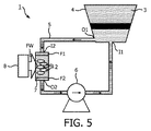
図5は、溶媒3に材料2を煎じるための、本発明による装置1の第5の実施態様を示す。図1に示される装置に含まれる要素に加えて、前記第2の容器は、入口I2を持ち、これは第1のフィルターF1を介して前記パイプへ接続され、及び出口O2を持ち、これは第2のフィルターF2を介して前記パイプに接続される。これらのフィルターは、材料が前記第2の容器から出ないことを保証するためである。前記溶媒が前記第2の容器へ入ると、前記溶媒の循環により材料を前記第2の容器から押し出してパイプに沿って分散させる。これらのフィルターを用いることは、前記溶媒流速が、前記材料の量に照らしてむしろ重要である場合や、材料が前記パイプの内部断面よりも小さい場合に特にそうである。このフィルターにより、材料は受容器内に保持される。例えば、プラスチック又は金属からなり、メッシュ又はネット構造を持つフィルターが使用され得る。前記フィルターは、煎じる工程を開始する前に、ユーザーにより前記材料が受容器内に導入された後、受容器に密閉されるか付設され得る。
FIG. 5 shows a fifth embodiment of the
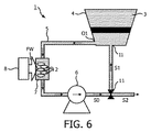
図6は、溶媒3に材料2を煎じるための、本発明による装置1の第6の実施態様を示す。図1に示される装置に含まれる要素に加えて、この装置は、弁11を持ち、これが前記パイプ5の直列に設けられている。前記バルブは、前記溶媒を前記第1の容器の出口O1から前記第1の容器の前記入口I1への循環のための第1の位置と、前記溶媒を前記第1の容器から排出するための第2の位置を取る。前記第1の位置では、前記弁は前記パイプの区分S0を前記パイプの区分S1へ接続し、これは材料を煎じる間前記位置に対応する。前記第2の位置では、前記弁は前記パイプの区分S0を前記パイプの外部区分S2へ接続し、これは前記容器から排出する位置に対応する。結局、前記煎じる工程が終了すると、前記第1の容器内の溶媒は、材料から抽出された化合物を含むドリンク/飲料に対応する。前記第2の位置に前記弁が位置することで、容器4からの溶媒が、例えば前記溶媒を例えばグラスなどの他の受容器へ注ぎ込まれる。前記弁は、ユーザーにより手動で起動される弁、又はシステムにより煎じ時間が終了した場合にシステムにより起動される電気弁(図示されていない)であり得る。留意すべきは、弁11を用いる代わりに、前記第1の容器の底部に直接接続されたユーザーにより手動で起動されるタップを使用することも可能である。
FIG. 6 shows a sixth embodiment of the
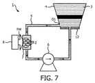
図7は、溶媒3に材料2を煎じるための、本発明による装置1の第7の実施態様を示す。図1に示される装置に含まれる要素に加えて、この装置は、加熱システム12を持ち、これが前記溶媒を加熱するために前記第1の容器に隣接して設けられている。前記加熱システムは、図示されているように前記第1の容器の基部内に設けられるか、又は前記第1の容器の壁に沿って設けられ得る(図示されていない)。前記加熱システムは、有利には、電流により供給される抵抗に対応するものである。前記加熱システムは、前記第1の容器内の溶媒を加熱するものであり、それにより加熱された溶媒が前記第2の容器内の材料間を循環することとなる。
FIG. 7 shows a seventh embodiment of the
図8は、溶媒3に材料2を煎じるための、本発明による装置1の第8の実施態様を示す。図1に示される装置に含まれる要素に加えて、この装置は、加熱システム13を持ち、これが前記溶媒を加熱するために前記パイプに隣接して設けられている。前記加熱システムは前記パイプの隣接する任意の区分に沿って設けられ得る。前記加熱システムは有利には、電流で供給される抵抗に対応するものである。前記加熱システムは、前記第1の容器内の溶媒を加熱するためであり、それにより加熱された溶媒が前記第2の容器内の材料間を循環することとなる。
FIG. 8 shows an eighth embodiment of the
図10は、溶媒内に材料を煎じる本発明による方法を示す。この方法は:
・記溶媒を含む第1の容器の出口から、前記第1の容器の入口へ、パイプ内の溶媒を循環させるステップST1、
・前記パイプに直列に設けられる第2の容器に含まれる前記材料に向けて波場を生成するステップST2を含む。
この方法は、図1から図8に示されるような本発明の装置により実施される種々のステップを含む。
FIG. 10 shows the method according to the invention of decocting material in a solvent. This method is:
Step ST1 of circulating the solvent in the pipe from the outlet of the first container containing the solvent to the inlet of the first container,
-Step ST2 which generates a wave field toward the material contained in the 2nd container provided in series with the pipe is included.
This method includes various steps performed by the apparatus of the present invention as shown in FIGS.
ここまで本発明は、図面及び発明の詳細な説明に基づき説明されてきたが、かかる図面及び説明は例示的なものであり、なんらを限定するものではない;本発明は開示された実施態様に限定されるものではない。例えば、前記容器及び受容器の形状は異なるものであってよく、これらは同じ機能を持つものであってもよい。図5から図8に示される装置の追加の構成は、ここでは図1に示された装置に基づき別々に説明されたが、これらの構成は、図1で示される装置に共に組み込まれることができる。特許請求の範囲で、用語「含む」とは、他の要素、ステップを除外するものではなく、用語「ひとつの」とは複数を除外するものではない。特許請求の範囲の符号は、本発明の範囲を限定するように解釈されるものではない。 Although the present invention has been described with reference to the drawings and detailed description of the invention, such drawings and description are illustrative and not restrictive; the present invention is not limited to the disclosed embodiments. It is not limited. For example, the shape of the container and the receptacle may be different and they may have the same function. Although additional configurations of the apparatus shown in FIGS. 5-8 have been described separately here based on the apparatus shown in FIG. 1, these configurations may be incorporated together in the apparatus shown in FIG. it can. In the claims, the term “comprising” does not exclude other elements and steps, and the term “single” does not exclude a plurality. The reference signs in the claims should not be construed as limiting the scope of the invention.
Claims (11)
・前記溶媒を含む第1の容器;
・前記第1の容器の入口と前記第1の容器の出口を接続するパイプ、
・前記溶媒を前記出口から前記入口へ循環させるための前記パイプに直列に設けられるポンプ、
・前記材料を含む第2の容器を含み、前記第2の容器が、前記パイプと直列して設けられ、前記パイプ内を循環する溶媒が前記材料間で循環することができ、
・前記第2の容器に隣接して設けられる波発生装置を含み、前記材料に向かって波を発生させる、装置。 An apparatus for decocting material in a solvent, said apparatus:
A first container containing the solvent;
A pipe connecting the inlet of the first container and the outlet of the first container;
A pump provided in series with the pipe for circulating the solvent from the outlet to the inlet;
Including a second container containing the material, wherein the second container is provided in series with the pipe, and a solvent circulating in the pipe can be circulated between the materials;
An apparatus comprising a wave generator provided adjacent to the second container and generating a wave toward the material.
・記溶媒を含む第1の容器の出口から、前記第1の容器の入口へ、パイプ内の溶媒を循環させるステップ、
・前記パイプに直列に設けられる第2の容器に含まれる前記材料に向けて波場を生成するステップ、を含む方法。 A method of decocting a material in a solvent, said method:
Circulating the solvent in the pipe from the outlet of the first container containing the solvent to the inlet of the first container;
Generating a wave field towards the material contained in a second container provided in series with the pipe.
Applications Claiming Priority (3)
| Application Number | Priority Date | Filing Date | Title |
|---|---|---|---|
| CNPCT/CN2010/002221 | 2010-12-30 | ||
| CN2010002221 | 2010-12-30 | ||
| PCT/IB2011/055845 WO2012090126A1 (en) | 2010-12-30 | 2011-12-21 | Method and apparatus for decocting ingredients in a solvent |
Publications (2)
| Publication Number | Publication Date |
|---|---|
| JP2014502545A true JP2014502545A (en) | 2014-02-03 |
| JP2014502545A5 JP2014502545A5 (en) | 2015-07-09 |
Family
ID=45560939
Family Applications (1)
| Application Number | Title | Priority Date | Filing Date |
|---|---|---|---|
| JP2013546796A Ceased JP2014502545A (en) | 2010-12-30 | 2011-12-21 | Method and apparatus for decoction of material in a solvent |
Country Status (6)
| Country | Link |
|---|---|
| US (1) | US9066619B2 (en) |
| EP (1) | EP2658384A1 (en) |
| JP (1) | JP2014502545A (en) |
| BR (1) | BR112013016412A2 (en) |
| RU (1) | RU2013135474A (en) |
| WO (1) | WO2012090126A1 (en) |
Cited By (1)
| Publication number | Priority date | Publication date | Assignee | Title |
|---|---|---|---|---|
| KR20170014599A (en) | 2015-07-30 | 2017-02-08 | (주)웰크론한텍 | Batch Type Concentrated Fluid Extractor |
Families Citing this family (7)
| Publication number | Priority date | Publication date | Assignee | Title |
|---|---|---|---|---|
| US9421477B2 (en) * | 2013-08-12 | 2016-08-23 | Green Extraction Technologies | Biomass fractionation and extraction apparatus |
| US11849877B2 (en) | 2013-12-31 | 2023-12-26 | Adrian Rivera Maynez Enterprises, Inc. | Portable coffee brewing system |
| DE102014018381A1 (en) * | 2014-12-15 | 2016-06-16 | Häussler & Sauter KG | Process for the preparation of beverages and apparatus for carrying out the process |
| CN105125407B (en) * | 2015-09-22 | 2019-01-18 | 王爱英 | A kind of decocting container |
| EP3381293A1 (en) * | 2017-03-28 | 2018-10-03 | De Jong Beheer B.V. | Method for treating a caffeine containing object, in particular coffee beans or tea leaves |
| US11399653B2 (en) * | 2018-08-24 | 2022-08-02 | Adrian Rivera | Beverage brewing system |
| US11627832B2 (en) | 2018-11-30 | 2023-04-18 | Adrian Rivera | Beverage brewer |
Citations (17)
| Publication number | Priority date | Publication date | Assignee | Title |
|---|---|---|---|---|
| JPS53101752A (en) * | 1977-02-17 | 1978-09-05 | Mitsubishi Electric Corp | High frequency defreezer |
| JPS54160786A (en) * | 1978-06-09 | 1979-12-19 | Sato Reiji | Preventing of precipitation and improving of flavor of coffee extract |
| JPS5683888U (en) * | 1979-11-28 | 1981-07-06 | ||
| JPS6096217A (en) * | 1983-10-31 | 1985-05-29 | 日本自動販売株式会社 | Coffee extractor |
| JPS6427432A (en) * | 1987-05-07 | 1989-01-30 | Bentz & Sohn Melitta | Method and apparatus for producing aromatic extract from coffee |
| JPH09192022A (en) * | 1996-01-19 | 1997-07-29 | Enomoto Koichi | Coffee percolator |
| JP2001300205A (en) * | 2000-04-24 | 2001-10-30 | Nissee:Kk | Polyfunctional extractor |
| JP2001521578A (en) * | 1997-02-14 | 2001-11-06 | マテリアルズ イノヴェーション、インコーポレイティッド | Pulsed and pressurized powder feed system and method of uniform particulate material delivery |
| JP2002028685A (en) * | 2000-07-17 | 2002-01-29 | Kobe Steel Ltd | Method and apparatus for aerobically treating organic liquid waste |
| US20060153758A1 (en) * | 2005-01-12 | 2006-07-13 | Vasco Cheung | Method and apparatus for the extraction of plant constituents |
| JP2006246704A (en) * | 2005-03-08 | 2006-09-21 | Yasuo Ishikawa | Apparatus for aging beverage |
| JP2006346372A (en) * | 2005-05-19 | 2006-12-28 | Duskin Co Ltd | Drinking water extraction and production machine |
| KR100788306B1 (en) * | 2006-08-02 | 2007-12-27 | 백관운 | Vacuum low temperature extraction equipment with ultrasonic vibrator |
| JP2008178439A (en) * | 2007-01-23 | 2008-08-07 | Tiger Vacuum Bottle Co Ltd | Beverage extractor |
| CN201182919Y (en) * | 2008-03-06 | 2009-01-21 | 永定采善堂生物质提炼有限公司 | Device for extracting alcohol-soluble plant composition |
| US20090041864A1 (en) * | 2007-08-09 | 2009-02-12 | John Warlick | Apparatus and Method for Cellular Extract Enhancement |
| JP2009082562A (en) * | 2007-10-01 | 2009-04-23 | Hoshizaki Electric Co Ltd | Beverage extraction apparatus |
Family Cites Families (7)
| Publication number | Priority date | Publication date | Assignee | Title |
|---|---|---|---|---|
| CN2535032Y (en) | 2001-11-09 | 2003-02-12 | 姚明勤 | High-efficient rapid acoustomagnetic radiating extractor for Chinese medicine |
| CN2600094Y (en) | 2003-02-28 | 2004-01-21 | 宜兴市爱康制药设备有限公司 | Improved microwave traditional Chinese medicine extracting device |
| CN2799038Y (en) | 2005-06-22 | 2006-07-26 | 宝士力(天津)科技发展有限公司 | Multifunctional extracting equipment |
| US20090246341A1 (en) | 2008-04-01 | 2009-10-01 | Pitner James H | System and Method for Brewing Tea |
| CN101371856B (en) | 2008-09-10 | 2011-09-28 | 长春海纳生物科技有限公司 | Device for continuously extracting Chinese medicine effective ingredient at normal temperature |
| GB2464806B (en) | 2008-10-31 | 2012-10-03 | Marigold Internat Pty Ltd | Kava extract production method and apparatus |
| CN202078768U (en) | 2011-05-25 | 2011-12-21 | 姚明勤 | Efficient, fast, super-strong and energy-collecting extraction device for traditional Chinese medicine |
-
2011
- 2011-12-21 RU RU2013135474/10A patent/RU2013135474A/en not_active Application Discontinuation
- 2011-12-21 WO PCT/IB2011/055845 patent/WO2012090126A1/en active Application Filing
- 2011-12-21 US US13/997,856 patent/US9066619B2/en not_active Expired - Fee Related
- 2011-12-21 BR BR112013016412A patent/BR112013016412A2/en not_active IP Right Cessation
- 2011-12-21 EP EP11815632.2A patent/EP2658384A1/en not_active Withdrawn
- 2011-12-21 JP JP2013546796A patent/JP2014502545A/en not_active Ceased
Patent Citations (17)
| Publication number | Priority date | Publication date | Assignee | Title |
|---|---|---|---|---|
| JPS53101752A (en) * | 1977-02-17 | 1978-09-05 | Mitsubishi Electric Corp | High frequency defreezer |
| JPS54160786A (en) * | 1978-06-09 | 1979-12-19 | Sato Reiji | Preventing of precipitation and improving of flavor of coffee extract |
| JPS5683888U (en) * | 1979-11-28 | 1981-07-06 | ||
| JPS6096217A (en) * | 1983-10-31 | 1985-05-29 | 日本自動販売株式会社 | Coffee extractor |
| JPS6427432A (en) * | 1987-05-07 | 1989-01-30 | Bentz & Sohn Melitta | Method and apparatus for producing aromatic extract from coffee |
| JPH09192022A (en) * | 1996-01-19 | 1997-07-29 | Enomoto Koichi | Coffee percolator |
| JP2001521578A (en) * | 1997-02-14 | 2001-11-06 | マテリアルズ イノヴェーション、インコーポレイティッド | Pulsed and pressurized powder feed system and method of uniform particulate material delivery |
| JP2001300205A (en) * | 2000-04-24 | 2001-10-30 | Nissee:Kk | Polyfunctional extractor |
| JP2002028685A (en) * | 2000-07-17 | 2002-01-29 | Kobe Steel Ltd | Method and apparatus for aerobically treating organic liquid waste |
| US20060153758A1 (en) * | 2005-01-12 | 2006-07-13 | Vasco Cheung | Method and apparatus for the extraction of plant constituents |
| JP2006246704A (en) * | 2005-03-08 | 2006-09-21 | Yasuo Ishikawa | Apparatus for aging beverage |
| JP2006346372A (en) * | 2005-05-19 | 2006-12-28 | Duskin Co Ltd | Drinking water extraction and production machine |
| KR100788306B1 (en) * | 2006-08-02 | 2007-12-27 | 백관운 | Vacuum low temperature extraction equipment with ultrasonic vibrator |
| JP2008178439A (en) * | 2007-01-23 | 2008-08-07 | Tiger Vacuum Bottle Co Ltd | Beverage extractor |
| US20090041864A1 (en) * | 2007-08-09 | 2009-02-12 | John Warlick | Apparatus and Method for Cellular Extract Enhancement |
| JP2009082562A (en) * | 2007-10-01 | 2009-04-23 | Hoshizaki Electric Co Ltd | Beverage extraction apparatus |
| CN201182919Y (en) * | 2008-03-06 | 2009-01-21 | 永定采善堂生物质提炼有限公司 | Device for extracting alcohol-soluble plant composition |
Cited By (1)
| Publication number | Priority date | Publication date | Assignee | Title |
|---|---|---|---|---|
| KR20170014599A (en) | 2015-07-30 | 2017-02-08 | (주)웰크론한텍 | Batch Type Concentrated Fluid Extractor |
Also Published As
| Publication number | Publication date |
|---|---|
| US20130287908A1 (en) | 2013-10-31 |
| WO2012090126A1 (en) | 2012-07-05 |
| US9066619B2 (en) | 2015-06-30 |
| BR112013016412A2 (en) | 2019-09-24 |
| EP2658384A1 (en) | 2013-11-06 |
| RU2013135474A (en) | 2015-02-10 |
Similar Documents
| Publication | Publication Date | Title |
|---|---|---|
| JP2014502545A (en) | Method and apparatus for decoction of material in a solvent | |
| JP2014502545A5 (en) | ||
| US20200154929A1 (en) | Coffee maker with features for rapid and/or multiple extraction processes, and associated systems and methods | |
| JP2014502544A (en) | Method and apparatus for decoction of material in a solvent | |
| JPH0614716A (en) | Method for extracting active ingredient of dry plant and extracting apparatus | |
| JP2014502544A5 (en) | ||
| US20080032030A1 (en) | Method and Apparatus for Producing Beverages from Coffee Beans Using Ultrasound Energy | |
| KR102181088B1 (en) | Extractor and Extraction System with High Efficiency and Hybrid Extraction Method Using This | |
| CN105543062A (en) | Preparation method of rosemary tea vinegar | |
| CN103907877A (en) | Method for preparing ginger extract with aid of efficient and circulatory pulsed ultrasound wave | |
| JP2006223531A (en) | Extraction method and extraction apparatus | |
| CN103555425B (en) | A kind of method utilizing high-frequency ultrasonic cavitation technology to prepare jasmine concrete | |
| CN107156361A (en) | A kind of cold brew tea preparation method and its device | |
| CN107126091A (en) | A kind of folliculus formula coffee strainer | |
| CN103281912B (en) | For the method and apparatus of the batching of infusion in a solvent | |
| JPH07135955A (en) | Alcoholic beverage | |
| CN108094623A (en) | Honeysuckle tea electuary and preparation method thereof | |
| CN104367704B (en) | A kind of extracting method of matrimony vine | |
| CN106212696A (en) | A kind of preparation method of refrigerant green bean juice beverage | |
| CN103298353B (en) | For the method and apparatus of the batching of infusion in a solvent | |
| RU2532989C1 (en) | Alcohol-free beverage production method | |
| CN109096344A (en) | A kind of extracting method of panoxadiol type saponin(e | |
| TW201521589A (en) | Method for extracting tea from tealeaf and tealeaf extracting apparatus thereof | |
| CN205181076U (en) | Health -preserving pot | |
| CN106338566A (en) | Detection method of residual pesticides in jasmine tea |
Legal Events
| Date | Code | Title | Description |
|---|---|---|---|
| A621 | Written request for application examination |
Free format text: JAPANESE INTERMEDIATE CODE: A621 Effective date: 20141218 |
|
| A521 | Request for written amendment filed |
Free format text: JAPANESE INTERMEDIATE CODE: A523 Effective date: 20150522 |
|
| A977 | Report on retrieval |
Free format text: JAPANESE INTERMEDIATE CODE: A971007 Effective date: 20151028 |
|
| A131 | Notification of reasons for refusal |
Free format text: JAPANESE INTERMEDIATE CODE: A131 Effective date: 20151117 |
|
| A521 | Request for written amendment filed |
Free format text: JAPANESE INTERMEDIATE CODE: A523 Effective date: 20151228 |
|
| A02 | Decision of refusal |
Free format text: JAPANESE INTERMEDIATE CODE: A02 Effective date: 20160405 |
|
| A521 | Request for written amendment filed |
Free format text: JAPANESE INTERMEDIATE CODE: A523 Effective date: 20160620 |
|
| A911 | Transfer to examiner for re-examination before appeal (zenchi) |
Free format text: JAPANESE INTERMEDIATE CODE: A911 Effective date: 20160705 |
|
| A01 | Written decision to grant a patent or to grant a registration (utility model) |
Free format text: JAPANESE INTERMEDIATE CODE: A01 Effective date: 20160802 |
|
| A045 | Written measure of dismissal of application [lapsed due to lack of payment] |
Free format text: JAPANESE INTERMEDIATE CODE: A045 Effective date: 20161220 |