JP2014202702A - Inspection device and inspection method - Google Patents
Inspection device and inspection method Download PDFInfo
- Publication number
- JP2014202702A JP2014202702A JP2013081280A JP2013081280A JP2014202702A JP 2014202702 A JP2014202702 A JP 2014202702A JP 2013081280 A JP2013081280 A JP 2013081280A JP 2013081280 A JP2013081280 A JP 2013081280A JP 2014202702 A JP2014202702 A JP 2014202702A
- Authority
- JP
- Japan
- Prior art keywords
- axis
- wiring
- supply unit
- inspection
- signal
- Prior art date
- Legal status (The legal status is an assumption and is not a legal conclusion. Google has not performed a legal analysis and makes no representation as to the accuracy of the status listed.)
- Pending
Links
Images


Classifications
-
- G—PHYSICS
- G09—EDUCATION; CRYPTOGRAPHY; DISPLAY; ADVERTISING; SEALS
- G09G—ARRANGEMENTS OR CIRCUITS FOR CONTROL OF INDICATING DEVICES USING STATIC MEANS TO PRESENT VARIABLE INFORMATION
- G09G3/00—Control arrangements or circuits, of interest only in connection with visual indicators other than cathode-ray tubes
- G09G3/006—Electronic inspection or testing of displays and display drivers, e.g. of LED or LCD displays
-
- G—PHYSICS
- G09—EDUCATION; CRYPTOGRAPHY; DISPLAY; ADVERTISING; SEALS
- G09G—ARRANGEMENTS OR CIRCUITS FOR CONTROL OF INDICATING DEVICES USING STATIC MEANS TO PRESENT VARIABLE INFORMATION
- G09G2330/00—Aspects of power supply; Aspects of display protection and defect management
- G09G2330/12—Test circuits or failure detection circuits included in a display system, as permanent part thereof
Abstract
Description
本発明は、タッチパネルの電気的特性を検出して、タッチパネルを検査する検査装置に関し、より詳しくは、交流信号の印加と電流信号の測定を複数の配線同時に実施することにより、タッチパネルの位置検出機能を高速で検査することができる検査装置及び検査方法に関する。
尚、本発明は、タッチパネルのように、x軸方向及びy軸方向にマトリクス状に配列される配線(又はパタ−ン)を有する検査対象物に対して検査を好適に実施することができ、そのような検査対象物を総称して、本明細書では「タッチパネル」と称する。
The present invention relates to an inspection apparatus for inspecting a touch panel by detecting electrical characteristics of the touch panel. More specifically, the present invention relates to a position detection function of a touch panel by simultaneously applying an AC signal and measuring a plurality of wires. The present invention relates to an inspection apparatus and an inspection method capable of inspecting at high speed.
In addition, this invention can test suitably with respect to the test object which has the wiring (or pattern) arranged in a matrix form in the x-axis direction and the y-axis direction like a touch panel, Such inspection objects are collectively referred to as “touch panel” in this specification.
従来、タッチパネル(又は、タッチスクリ−ンやタッチ画面)と呼ばれるITO膜上に形成されるx軸方向及びy軸方向に形成されるマトリクス状に配置される配線を有する検査対象物は、x軸方向とy軸方向に配置される夫々の配線に夫々接触子(針状の導通プロ−ブ)を接触させて、各配線の導通と隣接する配線との短絡の検査が実施されていた。 Conventionally, an inspection object having wiring arranged in a matrix formed in an x-axis direction and a y-axis direction formed on an ITO film called a touch panel (or a touch screen or a touch screen) is an x-axis. A contact (needle-like conduction probe) is brought into contact with each of the wirings arranged in the direction and the y-axis direction, and inspection of a short circuit between each wiring and an adjacent wiring has been performed.
しかしながら、このように接触子を各配線に接触させて検査を実施する方法では、ITO膜に形成される配線と接触子に安定性がなく、酸化膜による接触抵抗の不安定性から電気的特性が正確に測定できない問題を有していた。また、接触子がタッチパネルの表示部位を形成する表示配線と圧接されることになるため、表示配線に接触子が触れることによる打痕が形成される問題を有していた。 However, in the method in which the contact is in contact with each wiring as described above, the wiring formed on the ITO film and the contact are not stable, and the electrical characteristics are unstable due to the instability of the contact resistance due to the oxide film. It had a problem that could not be measured accurately. Further, since the contact is pressed into contact with the display wiring forming the display part of the touch panel, there is a problem that a dent is formed when the contact touches the display wiring.
一方、特許文献1に開示されるように、組み立てられたタッチパネル上の所定のタッチ入力位置の検出を精度良く行うことができるタッチパネル全体の抵抗値等の電気的特性を正確に検査する検査技術が提案されている。このように、組み立てられたタッチパネルの機能の電気的特性を検査する技術が開示されている。 On the other hand, as disclosed in Patent Document 1, there is an inspection technique for accurately inspecting electrical characteristics such as a resistance value of the entire touch panel that can accurately detect a predetermined touch input position on the assembled touch panel. Proposed. Thus, a technique for inspecting the electrical characteristics of the function of the assembled touch panel is disclosed.
また、特許文献1に開示される技術以外にも、タッチパネルは、上記の如く、x軸配線とy軸配線がクロスするように配置されているため、このx軸配線とy軸配線がクロスする交点箇所に接触子を接触させ、x軸配線とy軸配線から夫々検査信号を供給して、接触子からの検出信号からx軸配線とy軸配線の良/不良の判定を実施している。 In addition to the technique disclosed in Patent Document 1, since the touch panel is arranged so that the x-axis wiring and the y-axis wiring cross as described above, the x-axis wiring and the y-axis wiring cross. A contact is brought into contact with the intersection, an inspection signal is supplied from each of the x-axis wiring and the y-axis wiring, and whether the x-axis wiring and the y-axis wiring are good or bad is determined from the detection signal from the contact. .
しかしながら、このような検査方法では、x軸配線の総数とy軸配線の総数との乗算分だけ検査を実施する必要があり、このため、検査時間が冗長してしまう問題を有していた。 However, in such an inspection method, it is necessary to perform the inspection by the product of the total number of x-axis wirings and the total number of y-axis wirings, and thus there is a problem that the inspection time becomes redundant.
近年では、生産性を向上させる要求が高まっており、タクトタイムを短縮し、短時間で検査を完了させる必要がある。また特に近年では、タッチパネルがマルチタッチできる入力手段として利用されるため、パネル面全体が正確に位置検出機能を有しているか短時間で評価する要求が高まっている。 In recent years, demands for improving productivity are increasing, and it is necessary to shorten the tact time and complete the inspection in a short time. Particularly in recent years, since the touch panel is used as an input means capable of multi-touch, there is an increasing demand for evaluating in a short time whether the entire panel surface has a position detecting function accurately.
本発明は、このような実情に鑑みてなされたもので交流信号の印加と電流信号の測定を複数の配線同時に実施することにより、タッチパネルの位置検出機能を高速で検査することができる検査装置及び検査方法に関する。 The present invention has been made in view of such circumstances, and an inspection apparatus that can inspect the position detection function of a touch panel at high speed by simultaneously applying an AC signal and measuring a plurality of wirings, and It relates to inspection methods.
請求項1記載の発明は、複数のx軸配線のx軸表示配線と複数のy軸配線のy軸表示配線が直交して配置される検査物の表示配線の検査装置であって、所定の電圧を有する交流信号を供給する第一供給部と、該所定の電圧を有するとともに該交流信号と180度位相の相違する交流信号を供給する第二供給部を有する電源手段と、前記複数のy軸配線から所望のy軸配線を、前記電源手段の第一供給部及び/又は第二供給部と、電気接続させる接続手段と、前記複数のx軸配線と電気的に夫々接続される電流検出部を複数備える電流検出手段と、前記電流検出手段の電流検出部からの検出値を基に配線の評価を行う評価手段と、前記電源手段、前記接続手段、前記電流検出手段と前記評価手段の制御を行い、表示配線の検査を実施する制御手段を有し、前記制御手段は、前記接続手段が行う前記電源手段と前記y軸配線の接続において、前記第一供給部と接続される前記y軸配線の数と前記第二供給部と接続される前記y軸配線の数を一定となるよう制御を促すことを特徴とする。
請求項2記載の発明は、前記制御手段は、前記接続手段の制御が全ての前記y軸配線に対して順番に行われることを特徴とする。
請求項3記載の発明は、前記第一供給部に接続される前記y軸配線と前記第二供給部に接続される前記y軸配線の配置が、所定の順番に設定されていることを特徴とする。
請求項4記載の発明は、前記配置は、前記第一供給部又は前記第二供給部に接続される前記y軸配線が、三つ及び/又は二つ連続して並設される配置を有することを特徴とする。
請求項5記載の発明は、前記配置は、前記第一供給部又は前記第二供給部に接続される前記y軸配線が、該第二供給部又は該第一供給部に接続される一つの前記y軸配線を挟み込むような配置を有していることを特徴とする。
請求項6記載の発明は、前記第一供給部に接続される前記y軸配線と、前記第二供給部に接続される前記y軸配線が同数であることを特徴とする。
請求項7記載の発明は、前記電源手段は、電圧値がゼロである第三供給部を有し、
前記接続手段が、前記第三供給部を所望の前記y軸配線に接続することを特徴とする。
請求項8記載の発明は、前記評価手段は、前記電流検出部からの検出値を基に、検査物の平面度を算出することにより、前記検査物の評価を行うことを特徴とする。
請求項9記載の発明は、複数のx軸配線のx軸表示配線と複数のy軸配線のy軸表示配線が直交して配置される検査物の表示配線の検査方法であって、所定のy軸配線に第一交流信号を供給するとともに、他の所定のy軸配線に該交流信号と大きさが同じで180度位相の相違する第二交流信号を供給するステップと、複数のx軸配線から夫々の該x軸配線からの電気信号を検出するステップと、これらのステップが繰り返し行われて、複数の前記電気信号を収集して、これらの電気信号を基に表示配線の評価を行うステップとを有し、前記交流信号を供給するステップにおいて、第一交流信号が供給されるy軸配線の数と、第二交流信号が供給されるy軸配線の数が一定となるよう制御されていることを特徴とする。
The invention described in claim 1 is an inspection device display wiring inspection apparatus in which an x-axis display wiring of a plurality of x-axis wirings and a y-axis display wiring of a plurality of y-axis wirings are arranged orthogonally, Power supply means having a first supply part for supplying an AC signal having a voltage, a second supply part for supplying an AC signal having the predetermined voltage and having a phase difference of 180 degrees from the AC signal, and the plurality of y Connection means for electrically connecting a desired y-axis wiring from the axial wiring to the first supply part and / or the second supply part of the power supply means, and current detection electrically connected to the plurality of x-axis wirings, respectively. A plurality of current detection means, an evaluation means for evaluating wiring based on a detection value from the current detection section of the current detection means, the power supply means, the connection means, the current detection means, and the evaluation means. Control means to control and inspect the display wiring In the connection of the power supply means and the y-axis wiring performed by the connecting means, the control means is connected to the number of the y-axis wirings connected to the first supply unit and the second supply unit. Control is urged to keep the number of y-axis wirings constant.
The invention according to
The invention according to
According to a fourth aspect of the present invention, the arrangement has an arrangement in which three and / or two y-axis wirings connected to the first supply unit or the second supply unit are continuously arranged in parallel. It is characterized by that.
According to a fifth aspect of the present invention, the arrangement is such that the y-axis wiring connected to the first supply unit or the second supply unit is connected to the second supply unit or the first supply unit. It has an arrangement that sandwiches the y-axis wiring.
The invention described in
The invention according to claim 7 is characterized in that the power supply means has a third supply unit whose voltage value is zero,
The connection means connects the third supply unit to a desired y-axis wiring.
The invention according to claim 8 is characterized in that the evaluation means evaluates the inspection object by calculating a flatness of the inspection object based on a detection value from the current detection unit.
The invention according to
請求項1及び9記載の発明によれば、大きさが同じで180度位相が相違する二つの交流信号を第一供給部と第二供給部によりy軸配線へ供給するとともに、この第一供給部と第二供給部に接続されるy軸配線の数を一定にして、表示配線の検査が実施されるため、一定出力での表示配線の動作検査を行うことで、検査物の表示配線の特性を基に検査が実施される。このため、タッチパネルの位置検出機能を高速で検査することができる。
請求項2記載の発明によれば、接続手段が全てのy軸配線に対して順番に実施されるので、タッチパネルの表示配線全体に対して効率良く検査を実施することができる。
請求項3記載の発明によれば、第一供給部に接続されるy軸配線と第二供給部に接続されるy軸配線の配置が、所定の順番に設定されているので、供給される交流信号により検査状態を設定して検査することができる。
請求項4記載の発明によれば、第一供給部と第二供給部の配置が、少なくとも第一供給部又は第二供給部に接続されるy軸配線が、三つ及び/又は二つ連続して並設されているので、三つに並設される場合には真ん中のy軸配線は両隣のy軸配線と等電位で検査することができ、二つに並設される場合にはy軸配線の一方片側のy軸配線は等電位で他方片側のy軸配線は非等電位という検査条件を設定することができる。
請求項5記載の発明によれば、第一供給部又は第二供給部に接続されるy軸配線に挟まれるように第二供給部又は第一供給部に接続されるy軸配線となるよう配置されるので、他の供給部からの交流信号の影響を確認することができる。
請求項6記載の発明によれば、第一供給部に接続されるy軸配線と、第二供給部に接続されるy軸配線が同数であるので、タッチパネルに供給される交流信号の出力をゼロとして検査することができる。
請求項7記載の発明によれば、電源手段が電圧値がゼロである第三供給部を利用して、y軸配線に供給することになるので、信号印加の無いy軸配線を設定して検査を行うことができる。
請求項8記載の発明によれば、評価手段は、電流検出部からの検出値を基に、検査物の平面度を算出することができるので、平面度が突出するような位置情報を把握し、当該位置情報によりタッチパネルの不良部位を特定することができる。
According to the first and ninth aspects of the present invention, the two AC signals having the same magnitude but different in phase by 180 degrees are supplied to the y-axis wiring by the first supply unit and the second supply unit. The display wiring is inspected with a constant number of y-axis wirings connected to the second supply section and the second supply section. Therefore, by performing an operation inspection of the display wiring at a constant output, Inspection is performed based on the characteristics. For this reason, the position detection function of the touch panel can be inspected at high speed.
According to the second aspect of the present invention, since the connecting means is sequentially performed on all the y-axis wirings, the entire display wiring of the touch panel can be efficiently inspected.
According to the invention described in
According to the invention described in
According to the fifth aspect of the present invention, the y-axis wiring is connected to the second supply unit or the first supply unit so as to be sandwiched between the y-axis wirings connected to the first supply unit or the second supply unit. Since it is arrange | positioned, the influence of the alternating current signal from another supply part can be confirmed.
According to the sixth aspect of the invention, since the number of y-axis wirings connected to the first supply unit and the number of y-axis wirings connected to the second supply unit are the same, the output of the AC signal supplied to the touch panel can be performed. Can be tested as zero.
According to the seventh aspect of the present invention, since the power supply means supplies the y-axis wiring using the third supply unit whose voltage value is zero, the y-axis wiring without signal application is set. Inspection can be performed.
According to the invention described in claim 8, since the evaluation means can calculate the flatness of the inspection object based on the detection value from the current detection unit, the evaluation means grasps position information where the flatness protrudes. The defective part of the touch panel can be specified by the position information.
本発明を実施するための最良の形態を説明する。
本検査装置は、タッチパネルのようなx軸方向とy軸方向のマトリクス状に配置される複数の配線を有する基板やガラス基板に対して、検査効率を向上させることができる。
このため、まず、本検査装置の検査対象となるタッチパネルについて簡単に説明する。
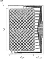
図1は、本発明の検査対象となるタッチパネルの一実施形態を示す概略平面図である。この図1のタッチパネルTPでは、ガラス基板上にx軸方向に配置されるx軸配線とy軸方向に配置されるy軸配線が夫々複数配置されている。この図1では、x軸配線が14本(符号で示されるLine:X1〜Line:Xe)形成され、y軸配線が8本(符号で示されるLine:Y1〜Line:Y8)形成されている。
タッチパネルTPのx軸配線とy軸配線は、これらの配線にて画面上のタッチエリア(P1とP2で覆われる部分)を覆うように配置されるため、図1で示す如き1本のx軸配線(及びy軸配線)が幅広部と幅狭部が繰り返して形成されることにより、タッチエリア全体を覆うように形成される。このように形成されることにより、タッチパネルTPが使用された場合に、タッチされた箇所(接触箇所)がどのx軸配線とどのy軸配線上に位置するのかを検出することができる。このタッチエリアは、x軸配線のx軸表示配線xPと、y軸配線のy軸表示配線yPから形成される。
The best mode for carrying out the present invention will be described.
This inspection apparatus can improve inspection efficiency with respect to a substrate or a glass substrate having a plurality of wirings arranged in a matrix in the x-axis direction and the y-axis direction, such as a touch panel.
For this reason, first, a touch panel to be inspected by this inspection apparatus will be briefly described.
FIG. 1 is a schematic plan view showing an embodiment of a touch panel to be inspected according to the present invention. In the touch panel TP of FIG. 1, a plurality of x-axis wirings arranged in the x-axis direction and y-axis wirings arranged in the y-axis direction are arranged on the glass substrate. In FIG. 1, 14 x-axis wirings (line: X1 to Line: Xe indicated by reference numerals) are formed, and eight x-axis wirings (line: Y1 to Line: Y8 indicated by reference numerals) are formed. .
Since the x-axis wiring and y-axis wiring of the touch panel TP are arranged so as to cover the touch area (the portion covered by P1 and P2) on the screen with these wirings, one x-axis as shown in FIG. The wiring (and the y-axis wiring) is formed so as to cover the entire touch area by repeatedly forming the wide portion and the narrow portion. By being formed in this way, when the touch panel TP is used, it is possible to detect on which x-axis wiring and on which y-axis wiring the touched location (contact location) is located. This touch area is formed by x-axis display wiring xP of x-axis wiring and y-axis display wiring yP of y-axis wiring.
図1のタッチパネルTPでは、x軸配線とy軸配線が、夫々14本と8本に形成されているが、これは特に限定されるものではなく、タッチパネル製造者によって適宜調整される。また、タッチパネルTPのタッチエリアや後述するタブ配線もその製造者により適宜調整されて形成され、幅広部と幅狭部の長さやその大きさもタッチパネル製造者により適宜調整される。 In the touch panel TP of FIG. 1, the x-axis wiring and the y-axis wiring are formed in 14 and 8, respectively, but this is not particularly limited, and is appropriately adjusted by the touch panel manufacturer. Further, the touch area of the touch panel TP and tab wiring described later are also formed by being adjusted as appropriate by the manufacturer, and the length and the size of the wide portion and the narrow portion are also appropriately adjusted by the touch panel manufacturer.
これらのx軸配線とy軸配線は、その一端がドライバなどの電子部品と接続が可能なように夫々、x軸タブ配線xTとy軸タブ配線yT(タブ配線部T)が形成されており、他の電子部品との電気的接続部が夫々延設されて形成されている。このタブ配線部Tは、タッチエリアから平面視において離間した場所に形成され、電気的接続ができるようにされている。図1のタッチパネルTPでは、紙面に向かって右側に夫々(x軸配線とy軸配線)のタブ配線部Tが形成されている。このタブ配線部Tは、タッチエリア以外の場所に一箇所に並列して形成されることができる。x軸配線は、x軸表示配線xPとx軸タブ配線xTとから形成されてなり、y軸配線は、y軸表示配線yPとy軸タブ配線yTとから形成されている。
なお、本明細書では、説明の都合上、x軸表示配線xP及び/又はy軸表示配線yPを示す場合には表示配線w1とし、x軸タグ配線xT及び/又はy軸タグ配線yTをタグ配線w2とする。
These x-axis wiring and y-axis wiring are respectively formed with x-axis tab wiring xT and y-axis tab wiring yT (tab wiring portion T) so that one end can be connected to an electronic component such as a driver. The electrical connection portions with other electronic components are formed so as to extend. The tab wiring portion T is formed at a location separated from the touch area in plan view so as to be electrically connected. In the touch panel TP of FIG. 1, tab wiring portions T of (x-axis wiring and y-axis wiring) are formed on the right side as viewed in the drawing. The tab wiring portion T can be formed in parallel at one place in a place other than the touch area. The x-axis wiring is formed by the x-axis display wiring xP and the x-axis tab wiring xT, and the y-axis wiring is formed by the y-axis display wiring yP and the y-axis tab wiring yT.
In this specification, for convenience of explanation, when the x-axis display wiring xP and / or the y-axis display wiring yP is shown, the display wiring w1 is used, and the x-axis tag wiring xT and / or the y-axis tag wiring yT is used as a tag. The wiring is w2.
本検査装置1は、電源手段2、接続手段3、電流検出手段4、評価手段5と制御手段6を有している。図2では、本検査装置1の概略構成を示す図である。尚、図2で示されるタッチパネルTPはx軸配線が5本形成され、y軸配線が4本形成されている。
The inspection apparatus 1 includes a
電源手段2は、所定の電圧を有する交流信号を供給する第一供給部21と、この所定の電圧を有するとともに交流信号と180度位相の相違する交流信号を供給する第二供給部22を有している。第一供給部21と第二供給部22は、交流信号を発生させる交流電源を用いることができる。なお、第一供給部21と第二供給部22は互いに180度位相の相違する交流信号を発生させるため、出力が合計されるとゼロになる。
The power supply means 2 includes a
第一供給部21と第二供給部22は、例えば、二つの交流電源をその間を接地して、二つの交流電源を直列接続し、位相を調整することで設定することができる(図2参照)。この第一供給部21と第二供給部22が供給する交流信号は、例えば、周波数が10k〜1000kHzの範囲で、実効値が1〜10Vの範囲の電圧値を有する交流信号に設定することができる。
The
電源手段2には、図示しない第三供給部(図示せず)を設けることができる。この第三供給部は、出力がゼロである信号を供給するように設定される。この第三供給部は、例えば、第一供給部21と第二供給部22の間の接地点される電位を、供給信号として設定することができる。
The power supply means 2 can be provided with a third supply section (not shown) (not shown). This third supply is set to supply a signal whose output is zero. The third supply unit can set, for example, a potential grounded between the
接続手段3は、複数のy軸配線ywから所望のy軸配線ywを選出して、電源手段2の第一供給部21及び/又は第二供給部22と、選出されたy軸配線ywを電気接続させる。この接続手段3は、y軸配線ywのy軸タブ配線ytwと接続され、y軸タブ配線ytwを経由して、y軸表示配線ytwに検査信号が供給されることになる。接続手段3は、例えば、y軸タブ配線ytwに接続する接触子31と、電源手段2の第一供給部21と第二供給部22との電気的接続される切替部32を利用することができる。接触子31はy軸タブ配線ytwの数と同数用意される。切替部32は、例えばON/OFF動作するスイッチ素子を採用することができる。電源手段2が第一供給部21と第二供給部22を備える場合には、夫々に接続される二つの切替部32が設けられ、第一乃至第三供給部の三つの供給部が設定される場合には三つの切替部32が設けられることになる。この切替部32の動作により、y軸配線ywと電源手段2のいずれからの供給部が導通接続されることになる。
The connecting
この接続手段3は、第一供給部21と接続されるy軸配線ywの数と、第二供給部22と接続されるy軸配線ywとが一定となるように制御されている。接続手段3が第一供給部21に接続されるy軸配線の数と第二供給部22に接続されるy軸配線の数を一定とすることによって、x軸配線xwに供給される検査信号の出力は常に一定となる。
The connecting means 3 is controlled such that the number of y-axis wirings yw connected to the
接続手段3は、第一供給部21と第二供給部22が夫々接続されるy時配線ywの数は一定であるが、第一供給部21と第二供給部22のy軸配線ywは同数であることが好ましい。この場合、x軸配線xwにはy軸配線ywからの信号の影響が結果的にゼロとなり、電流検出部41がx軸配線xwから検出する電流もゼロとなる。また、第三供給部を設定する場合も、第三供給部の供給する検査信号はゼロであるため、接続手段3によりx軸配線xwに供給される検査信号の出力は一定又はゼロとなる。
なお、接続手段3は、上記のような条件で動作するように制御手段6に制御されることになる。
In the connection means 3, the number of y-time wirings yw to which the
The connecting means 3 is controlled by the control means 6 so as to operate under the above conditions.
また、接続手段3は、第一供給部21に接続されるy軸配線ywと第二供給部22に接続されるy軸配線ywの配置が、所定の順番に設定されるように、後述する制御手段6に制御されることもできる。
例えば、接続手段3による配置には、第一供給部21に接続されるy軸配線ywを、三つ及び/又は二つ連続して並設される配置を採用することができる。第一供給部21に三つの連続したy軸配線ywが接続される組み合わせを持つよう制御される。三つ連続で第一又は第二供給部に接続されたy軸配線ywでは、その真ん中に位置するy軸配線ywは、両隣のy軸配線ywと等電位に接続されることになり、このような条件の場合のx軸配線xwの影響を電流検出部41は検出することになる。
The connecting means 3 will be described later so that the arrangement of the y-axis wiring yw connected to the
For example, the arrangement by the connection means 3 can employ an arrangement in which three and / or two y-axis wirings yw connected to the
また、接続手段3は、第一供給部21に二つの連続したy軸配線ywが接続される組み合わせを持つよう制御されることもできる。また同様に、第二供給部22と三つ又は二つの連続したy軸配線ywが接続される組み合わせを持つように制御される。この場合、第一又は第二供給部に接続される一方側のy軸配線ywは、一方隣側のy軸配線yw(第一又は第二供給部に接続される他方側のy軸配線yw)とは等電位となるが、他方隣側のy軸配線ywとは相違する電位となり、このような条件の場合のx軸配線xwの影響を電流検出部41は検出することになる。
Further, the connecting
また更に、接続手段3は、第一供給部21又は第二供給部22に接続されるy軸配線ywが、第二供給部22又は第一供給部21に接続される一つのy軸配線ywを挟み込むような配置となるよう制御される。この場合、挟み込まれたy軸配線ywは、相違する交流信号に接続されるy軸配線ywに挟まれることになり、このような条件の場合のx軸配線xwの影響を電流検出部41は検出することになる。
Further, the connecting
接続手段3の上記の如き配置は、制御手段6により制御されており、これら配置の組み合わせを順番に処理することで、タッチパネルTPの後述する評価を行うことができるようになる。
The arrangement of the connecting
電流検出手段4は、複数のx軸配線xwと電気的に夫々接続される電流検出部41を複数備えている。この電流検出手段4は、電流検出部41を検査対象となるタッチパネルTPのx軸配線xwの数だけ準備されることになる。電流検出部41は、例えば、電流計を採用することができる。電流検出部41は夫々が後述する評価手段5へ検出結果を送信する。この電流検出部41は、上記の電源手段2から接続手段3を介してy軸配線ywに供給される交流信号による影響をx軸配線xwが受け、その影響がx軸配線xwの電流として検出することになる。
The
評価手段5は、電流検出手段4の電流検出部41からの検出値を基に配線の評価を行う。この評価手段5は、電流検出部41の検出値の情報をy軸配線ywの情報と紐付けして記憶する記憶部(図示せず)を有しており、電流検出部41の検出結果を記憶する。この評価手段5は、電源手段2から供給される検査信号の状態情報も合わせて記憶される。この検査信号の状態情報とは、例えば、第一供給部21と接続されるy軸配線ywの情報や、第二供給部22と接続されるy軸配線ywの情報、更には第三供給部と接続されるy軸配線ywの情報などであり、第一乃至第三供給部が夫々供給した検査信号がどのy軸配線ywに供給されたかを把握することができる。
The
本検査装置1では、x軸配線xwに供給される電源手段2からの供給される検査信号は一定の出力であり、この一定出力の検査信号が繰り返し供給されることになるので、配線が良好に形成されている場合には検出値も一定となる。このため、評価手段5は収集される複数の検出値を基に、一定ではない検出値を測定し、その部位を特定することで、タッチパネルTPの位置検出機能の不良を検出することができる。 In this inspection apparatus 1, the inspection signal supplied from the power supply means 2 supplied to the x-axis wiring xw is a constant output, and this constant output inspection signal is repeatedly supplied, so that the wiring is good. The detection value is also constant when formed. For this reason, the evaluation means 5 can detect a defect in the position detection function of the touch panel TP by measuring a non-constant detection value based on a plurality of detection values collected and specifying the part.
評価手段5は、上記の如く、電流検出部41からの検出値を基に、タッチパネルTPの平面度を算出することにより、タッチパネルTPの配線(特に表示配線)の評価を行うことができる。具体的には、電流検出部41からの検出値を基にして平均値との差や偏差を求めたり、予め設定される基準値から検出値の差を算出したりすることで、各配線又はx軸配線とy軸配線の交点毎の出力を算出し、この算出結果を平面度としてプロットする。このとき、良好なタッチパネルTPであれば、各配線又は各交点で均一な出力を有するため、平面度は均一となる。しかしながら、配線に不良が存在すると、不良の影響を受けた出力が検出されることになり、平面度が粗いものとなる。
なお、評価手段5は、上記の如き検査値を基にタッチパネルTPの表示配線の評価を行うが、可視化することで、タッチパネルTPの評価を単純に且つ容易に行うことができるようになる。
As described above, the
The
制御手段6は、電源手段2、接続手段3、電流検出手段4(電流検出部41)又は評価手段5の制御を行い、上記の表示配線の検査を実施する。この制御手段6は、接続手段3の制御が全てのy軸配線ywに対して順番に行われることによって、タッチパネルTPに形成される全ての表示配線の検査を実施することができる。
The control means 6 controls the power supply means 2, the connection means 3, the current detection means 4 (current detection unit 41) or the evaluation means 5 to perform the above-described display wiring inspection. The
本検査装置1が行う接続手段の電源手段の接続動作を説明する。
なお、図3では、電源手段2として第一乃至第三供給部が設定されており、便宜的に第一供給部21の交流信号を(+)とし、第二供給部22の交流信号を(−)とし、第三供給部からの信号を(0)としている。図3(a)はタッチパネルTPを模式的に示した図であり、x軸配線xwが8本、y軸配線ywが12本描かれている。(b)は第一乃至第三供給部を用いた検査手順(ステップS1からステップS12)が示されている。この図3の検査方法では、電源手段2と接続されるy軸配線ywは6本と設定されるとともに、6本から供給される交流信号は、その合計の出力がゼロとなるよう設定されている。
The connection operation of the power supply means of the connection means performed by the inspection apparatus 1 will be described.
In FIG. 3, first to third supply units are set as the power supply means 2. For convenience, the AC signal of the
この検査方法では、第一供給部21の交流信号(+)が二つのy軸配線ywに供給され、第二供給部22の交流信号(−)が二つのy軸配線ywに供給され、第三供給部の交流信号(0)が二つのy軸配線ywに供給されるようになっている。ステップS1では、y軸配線yw1とy軸配線yw2に第一供給部21が接続され、y軸配線yw3とy軸配線yw4に第二供給部22が接続され、y軸配線yw5とy軸配線yw6が接続されている。なお、制御手段6は、上記のように接続手段3が動作するように制御信号を送信するとともに、各x軸配線xwに接続される電流検出部41からの検出信号を評価手段5へ送信するように設定される。
In this inspection method, the AC signal (+) of the
次の検査工程として、y軸配線yw2とy軸配線yw3に第一供給部21が接続され、y軸配線yw4とy軸配線yw5に第二供給部22が接続され、y軸配線yw6とy軸配線yw7が接続される。この接続が実施されると、電流検出部41が夫々の電気信号を検出し、評価手段5へ検出値を送信する。
なお、この検査方法では、交流信号は(+)(+)(−)(−)(0)(0)の順番になっているが、上記の如き交流信号の合計がゼロとなれば、特にこの順番に限定されるものではない。
As the next inspection process, the
In this inspection method, the AC signals are in the order of (+) (+) (−) (−) (0) (0). If the sum of the AC signals as described above becomes zero, in particular, It is not limited to this order.
ステップS2の検査工程にて検出値が評価手段5へ送信されると、次のステップS3へ検査工程が移行される。ステップS3では、y軸配線yw3とy軸配線yw4に第一供給部21が接続され、y軸配線yw5とy軸配線yw6に第二供給部22が接続され、y軸配線yw7とy軸配線yw8が接続される。この接続が実施されると、電流検出部41が夫々の電気信号を検出し、評価手段5へ検出値を送信する。
同様の処理が、ステップS4からステップS12まで繰り返し実施され、y軸配線yw1からy軸配線yw12まで繰り返し処理が実施されることになる。
そして、y軸配線yw1からy軸配線yw12までの接続手段3により切替が行われ、その各検査工程での検出値が評価手段5に送信され、これらの検出値に基づいて評価が実施されることになる。なお、この場合、タッチパネルTPの位置検出機能に問題がなければ、供給される検査信号の合計出力がゼロであるため、電流検出手段4の検出値も一定値(例えば、ゼロ)が検出されることになる。もし、位置検出機能に問題があれば、特異な検出値が測定結果として得られ、その特異な部位をx軸配線とy軸配線からの位置情報により特定されることになる。
When the detected value is transmitted to the evaluation means 5 in the inspection process of step S2, the inspection process is shifted to the next step S3. In step S3, the
The same processing is repeatedly performed from step S4 to step S12, and the repeated processing is performed from the y-axis wiring yw1 to the y-axis wiring yw12.
Then, switching is performed by the connecting means 3 from the y-axis wiring yw1 to the y-axis wiring yw12, and the detection values in the respective inspection steps are transmitted to the evaluation means 5, and evaluation is performed based on these detection values. It will be. In this case, if there is no problem with the position detection function of the touch panel TP, the total output of the supplied inspection signals is zero, so that the detection value of the current detection means 4 is also detected as a constant value (for example, zero). It will be. If there is a problem with the position detection function, a specific detection value is obtained as a measurement result, and the specific part is specified by position information from the x-axis wiring and the y-axis wiring.
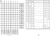
本検査装置1が行う接続手段の電源手段の他の接続動作を説明する。
なお、図4では、電源手段2として第一及び第二供給部が設定されており、便宜的に第一供給部21の交流信号を(+)とし、第二供給部22の交流信号を(−)としている。図4(a)はタッチパネルTPを模式的に示した図であり、x軸配線xwが8本、y軸配線ywが12本描かれている。(b)は第一及び第二供給部を用いた検査手順(ステップS1からステップS12)が示されている。
Another connection operation of the power supply means of the connection means performed by the inspection apparatus 1 will be described.
In FIG. 4, the first and second supply units are set as the power supply means 2. For convenience, the AC signal of the
この図4の検査方法では、電源手段2と接続されるy軸配線ywは9本と設定される。また、この検査方法では、第一供給部21と接続されるy軸配線ywが三つ連続して設定され、第二供給部22に接続される一つのy軸配線ywが設定され、第一供給部21と接続されるy軸配線ywが二つ連続して設定され、第二供給部22に接続される一つのy軸配線ywが設定され、第一供給部21に接続される一つのy軸配線ywが設定され、第二供給部22に接続される一つのy軸配線ywが設定され、この順番を一つの組として実施される。つまり、この検査方法では、交流信号は(+)(+)(+)(−)(+)(+)(−)(+)(−)の順に設定されることになる。なお、制御手段6は、上記のように接続手段3が動作するように制御信号を送信するとともに、各x軸配線xwに接続される電流検出部41からの検出信号を評価手段5へ送信するように設定される。
In the inspection method of FIG. 4, nine y-axis wirings yw connected to the power supply means 2 are set. In this inspection method, three y-axis wirings yw connected to the
次の検査工程(ステップS2)として、y軸配線yw2からy軸配線yw10までのy軸配線ywに対して、交流信号が(+)(+)(+)(−)(+)(+)(−)(+)(−)の順に設定されるように、制御手段6が接続手段3を動作制御することになる。この接続が実施されると、電流検出部41が夫々の電気信号を検出し、評価手段5へ検出値を送信する。
As the next inspection step (step S2), the AC signal is (+) (+) (+) (−) (+) (+) for the y-axis wiring yw from the y-axis wiring yw2 to the y-axis wiring yw10. The control means 6 controls the operation of the connection means 3 so as to be set in the order of (−) (+) (−). When this connection is carried out, the
ステップS2の検査工程にて検出値が評価手段5へ送信されると、次のステップS3へ検査工程が移行される。このステップS3でも、y軸配線yw3からy軸配線yw11に交流信号が(+)(+)(+)(−)(+)(+)(−)(+)(−)の順に設定されるように、制御手段6が接続手段3を動作制御することになる。この接続が実施されると、電流検出部41が夫々の電気信号を検出し、評価手段5へ検出値を送信する。
同様の処理が、ステップS4からステップS12まで繰り返し実施され、y軸配線yw1からy軸配線yw12まで繰り返し処理が実施されることになる。
そして、y軸配線yw1からy軸配線yw12までの接続手段3により切替が行われ、その各検査工程での検出値が評価手段5に送信され、これらの検出値に基づいて評価が実施されることになる。なお、この場合も、タッチパネルTPの位置検出機能に問題がなければ、供給される検査信号の合計出力が一定であるため、電流検出手段4の検出値も一定値が検出されることになる。もし、位置検出機能に問題があれば、特異な検出値が測定結果として得られ、その特異な部位をx軸配線とy軸配線からの位置情報により特定されることになる。
以上が本検査装置に関する構成の説明である。
When the detected value is transmitted to the evaluation means 5 in the inspection process of step S2, the inspection process is shifted to the next step S3. Also in this step S3, AC signals are set in the order of (+) (+) (+) (-) (+) (+) (-) (+) (-) from the y-axis wiring yw3 to the y-axis wiring yw11. Thus, the control means 6 controls the operation of the connection means 3. When this connection is carried out, the
The same processing is repeatedly performed from step S4 to step S12, and the repeated processing is performed from the y-axis wiring yw1 to the y-axis wiring yw12.
Then, switching is performed by the connecting means 3 from the y-axis wiring yw1 to the y-axis wiring yw12, and the detection values in the respective inspection steps are transmitted to the evaluation means 5, and evaluation is performed based on these detection values. It will be. In this case as well, if there is no problem with the position detection function of the touch panel TP, the total output of the supplied inspection signals is constant, so that the detection value of the current detection means 4 is also detected as a constant value. If there is a problem with the position detection function, a specific detection value is obtained as a measurement result, and the specific part is specified by position information from the x-axis wiring and the y-axis wiring.
The above is the description of the configuration relating to the present inspection apparatus.
次に、本発明の検査装置の動作について説明する。
本検査装置1にタッチパネルTPが設定されると、y軸配線ywには接続手段3の接触子31が導通接続され、x軸配線xwには電流検出手段4の電流検出部41が夫々導通接続される。このとき、制御手段6には、タッチパネルTPの検査に必要な情報が格納されることになる。例えば、タッチパネルTPのx/y軸配線の本数・位置情報などや第一供給部や第二供給部が供給する交流信号の出力情報や接続手順などの検査方法が格納される。
また、タッチパネルTPのx軸配線xwとy軸配線ywが夫々電流検出部41と接続手段3に接続される。このようにしてタッチパネルTPの検査準備が整えられる。検査準備が整うと検査が開始される。
Next, the operation of the inspection apparatus of the present invention will be described.
When the touch panel TP is set in the inspection apparatus 1, the
In addition, the x-axis wiring xw and the y-axis wiring yw of the touch panel TP are connected to the
制御手段6は、接続手段3を動作するための動作信号を送信する。このとき、所望する検査が実施されるよう電源手段2の第一供給部21と第二供給部22を、y軸配線yw1乃至yw4に夫々所望の組み合わせにより接続される。なお、電源手段3へ接続される組み合わせは、予め検査実施者により設定されることになる(例えば、図3又は図4参照)。
The control means 6 transmits an operation signal for operating the connection means 3. At this time, the
制御手段6が接続手段3に制御信号を送信した後に、x軸配線xw1乃至xw5に接続される電流検出部41が動作するよう促し、電流検出部41は電流を測定して検出値を評価手段5へ送信する。次に、制御手段6は、次の順番の検査を実施するよう接続手段3へ制御信号を送信し、同様に、電流検出部41が検出値を評価手段5へ送信する。
After the
この順番が最後まで繰り返されると、評価手段5は収集された検出値を基に検査対象のタッチパネルTPの平面度が算出される。この平面度に応じてタッチパネルTPの位置検出機能が良好であるか、不良箇所が存在するかが評価されることになる。特に、本検査装置や本検査方法では、一方の配線の数の検査手順で検査が可能となるため、従来の位置検査方法では約20秒の検査時間が必要であったものが、約2秒で検査することが可能となり、大幅に検査時間を短縮することが可能となる。 When this order is repeated to the end, the evaluation means 5 calculates the flatness of the touch panel TP to be inspected based on the collected detection values. Depending on the flatness, whether the position detection function of the touch panel TP is good or a defective part is evaluated. In particular, with this inspection device and this inspection method, inspection can be performed with the number of wiring inspection procedures, so the conventional position inspection method required about 20 seconds of inspection time, but about 2 seconds. It is possible to inspect with this, and the inspection time can be greatly shortened.
1・・・・検査装置
2・・・・電源手段
3・・・・接続手段
4・・・・電流検出手段
5・・・・評価手段
6・・・・制御手段
DESCRIPTION OF SYMBOLS 1 ...
Claims (9)
所定の電圧を有する交流信号を供給する第一供給部と、該所定の電圧を有するとともに該交流信号と180度位相の相違する交流信号を供給する第二供給部を有する電源手段と、
前記複数のy軸配線から所望のy軸配線を、前記電源手段の第一供給部及び/又は第二供給部と、電気接続させる接続手段と、
前記複数のx軸配線と電気的に夫々接続される電流検出部を複数備える電流検出手段と、
前記電流検出手段の電流検出部からの検出値を基に配線の評価を行う評価手段と、
前記電源手段、前記接続手段、前記電流検出手段と前記評価手段の制御を行い、表示配線の検査を実施する制御手段を有し、
前記制御手段は、
前記接続手段が行う前記電源手段と前記y軸配線の接続において、前記第一供給部と接続される前記y軸配線の数と前記第二供給部と接続される前記y軸配線の数を一定となるよう制御を促すことを特徴とする検査装置。 An inspection apparatus for a display wiring of an inspection object in which an x-axis display wiring of a plurality of x-axis wirings and a y-axis display wiring of a plurality of y-axis wirings are orthogonally arranged,
A first supply unit that supplies an AC signal having a predetermined voltage; and a power supply unit that includes a second supply unit that supplies the AC signal having the predetermined voltage and having a phase difference of 180 degrees from the AC signal;
Connection means for electrically connecting a desired y-axis wiring from the plurality of y-axis wirings to the first supply unit and / or the second supply unit of the power supply unit;
Current detection means comprising a plurality of current detection units electrically connected to the plurality of x-axis wirings,
Evaluation means for evaluating wiring based on a detection value from a current detection unit of the current detection means;
Control means for controlling the power supply means, the connection means, the current detection means and the evaluation means to inspect the display wiring;
The control means includes
In the connection between the power supply means and the y-axis wiring performed by the connecting means, the number of the y-axis wiring connected to the first supply unit and the number of the y-axis wiring connected to the second supply unit are constant. An inspection device characterized by prompting control so that
前記接続手段が、前記第三供給部を所望の前記y軸配線に接続することを特徴とする請求項6記載の検査装置。 The power supply means has a third supply unit whose voltage value is zero,
The inspection apparatus according to claim 6, wherein the connection unit connects the third supply unit to the desired y-axis wiring.
所定のy軸配線に第一交流信号を供給するとともに、他の所定のy軸配線に該交流信号と大きさが同じで180度位相の相違する第二交流信号を供給するステップと、
複数のx軸配線から夫々の該x軸配線からの電気信号を検出するステップと、
これらのステップが繰り返し行われて、複数の前記電気信号を収集して、これらの電気信号を基に表示配線の評価を行うステップとを有し、
前記交流信号を供給するステップにおいて、第一交流信号が供給されるy軸配線の数と、第二交流信号が供給されるy軸配線の数が一定となるよう制御されていることを特徴とする検査方法。 An inspection method for display wiring of an inspection object in which an x-axis display wiring of a plurality of x-axis wirings and a y-axis display wiring of a plurality of y-axis wirings are arranged orthogonally,
Supplying a first AC signal to a predetermined y-axis wiring and supplying a second AC signal having the same magnitude as that of the AC signal and a phase difference of 180 degrees to another predetermined y-axis wiring;
Detecting an electrical signal from each x-axis wiring from a plurality of x-axis wirings;
These steps are repeatedly performed, collecting a plurality of the electrical signals, and evaluating the display wiring based on these electrical signals,
In the step of supplying the AC signal, the number of y-axis wirings supplied with the first AC signal and the number of y-axis wirings supplied with the second AC signal are controlled to be constant. Inspection method to do.
Priority Applications (3)
| Application Number | Priority Date | Filing Date | Title |
|---|---|---|---|
| JP2013081280A JP2014202702A (en) | 2013-04-09 | 2013-04-09 | Inspection device and inspection method |
| PCT/JP2014/002006 WO2014167839A1 (en) | 2013-04-09 | 2014-04-08 | Inspection apparatus and inspection method |
| TW103113111A TWI489123B (en) | 2013-04-09 | 2014-04-09 | Inspecting apparatus and inspecting method |
Applications Claiming Priority (1)
| Application Number | Priority Date | Filing Date | Title |
|---|---|---|---|
| JP2013081280A JP2014202702A (en) | 2013-04-09 | 2013-04-09 | Inspection device and inspection method |
Publications (1)
| Publication Number | Publication Date |
|---|---|
| JP2014202702A true JP2014202702A (en) | 2014-10-27 |
Family
ID=51689260
Family Applications (1)
| Application Number | Title | Priority Date | Filing Date |
|---|---|---|---|
| JP2013081280A Pending JP2014202702A (en) | 2013-04-09 | 2013-04-09 | Inspection device and inspection method |
Country Status (3)
| Country | Link |
|---|---|
| JP (1) | JP2014202702A (en) |
| TW (1) | TWI489123B (en) |
| WO (1) | WO2014167839A1 (en) |
Cited By (1)
| Publication number | Priority date | Publication date | Assignee | Title |
|---|---|---|---|---|
| KR20160098038A (en) * | 2015-02-09 | 2016-08-18 | 니혼덴산리드가부시키가이샤 | Connection inspecting apparatus |
Families Citing this family (1)
| Publication number | Priority date | Publication date | Assignee | Title |
|---|---|---|---|---|
| CN106066237A (en) * | 2016-05-25 | 2016-11-02 | 广州市祈丰机电科技有限公司 | Touch screen maintenance craft flow process |
Family Cites Families (6)
| Publication number | Priority date | Publication date | Assignee | Title |
|---|---|---|---|---|
| DE3608148A1 (en) * | 1986-03-12 | 1987-09-24 | Schwab Technologieberatung | ARRANGEMENT FOR MONITORING AND DISPLAYING CHESS PARTIES |
| JP3359732B2 (en) * | 1994-03-29 | 2002-12-24 | 大日本印刷株式会社 | Defect detection method and defect detection device for linear electrode |
| US7151432B2 (en) * | 2001-09-19 | 2006-12-19 | Immersion Corporation | Circuit and method for a switch matrix and switch sensing |
| EP2330492B1 (en) * | 2006-06-09 | 2017-10-18 | Apple Inc. | Touch screen liquid crystal display |
| JP4634353B2 (en) * | 2006-09-20 | 2011-02-16 | オー・エイチ・ティー株式会社 | Circuit pattern inspection device |
| JP5533169B2 (en) * | 2010-04-13 | 2014-06-25 | 日本電産リード株式会社 | Inspection device |
-
2013
- 2013-04-09 JP JP2013081280A patent/JP2014202702A/en active Pending
-
2014
- 2014-04-08 WO PCT/JP2014/002006 patent/WO2014167839A1/en active Application Filing
- 2014-04-09 TW TW103113111A patent/TWI489123B/en not_active IP Right Cessation
Cited By (2)
| Publication number | Priority date | Publication date | Assignee | Title |
|---|---|---|---|---|
| KR20160098038A (en) * | 2015-02-09 | 2016-08-18 | 니혼덴산리드가부시키가이샤 | Connection inspecting apparatus |
| KR102469505B1 (en) * | 2015-02-09 | 2022-11-22 | 니혼덴산리드가부시키가이샤 | Connection inspecting apparatus |
Also Published As
| Publication number | Publication date |
|---|---|
| TW201439562A (en) | 2014-10-16 |
| TWI489123B (en) | 2015-06-21 |
| WO2014167839A1 (en) | 2014-10-16 |
Similar Documents
| Publication | Publication Date | Title |
|---|---|---|
| JP5391819B2 (en) | Touch panel inspection device | |
| JP6311223B2 (en) | Inspection device, calibration method of inspection device, and inspection method | |
| KR101005624B1 (en) | Inspection apparatus of touch panel | |
| JP6248406B2 (en) | Inspection apparatus and inspection method | |
| JP5533169B2 (en) | Inspection device | |
| JP5305111B2 (en) | Circuit pattern inspection device | |
| JP6368927B2 (en) | Single layer inspection object inspection apparatus and inspection method | |
| JP2014202702A (en) | Inspection device and inspection method | |
| JP5317554B2 (en) | Circuit board inspection apparatus and circuit board inspection method | |
| JP2007298422A (en) | Board inspection system and board inspection method | |
| JP6569506B2 (en) | Connection inspection device | |
| JP2014020858A (en) | Insulation inspection method and insulation inspection device | |
| JP2023057530A (en) | Measurement device, measurement system, and measurement method | |
| JP5899961B2 (en) | Insulation inspection device and insulation inspection method | |
| JP5415134B2 (en) | Inspection apparatus and inspection method | |
| JP5420303B2 (en) | Circuit board inspection apparatus and circuit board inspection method | |
| JP5944121B2 (en) | Circuit board inspection apparatus and circuit board inspection method | |
| KR101750446B1 (en) | test apparatus and method for pin miss | |
| JP2001084905A (en) | Inspection device for electrode and method therefor | |
| CN105866606B (en) | Connection inspection device | |
| JP2007298277A (en) | Board inspection system and board inspection method |