JP2014187771A - Vehicle - Google Patents
Vehicle Download PDFInfo
- Publication number
- JP2014187771A JP2014187771A JP2013060013A JP2013060013A JP2014187771A JP 2014187771 A JP2014187771 A JP 2014187771A JP 2013060013 A JP2013060013 A JP 2013060013A JP 2013060013 A JP2013060013 A JP 2013060013A JP 2014187771 A JP2014187771 A JP 2014187771A
- Authority
- JP
- Japan
- Prior art keywords
- power
- vehicle
- power supply
- external
- external device
- Prior art date
- Legal status (The legal status is an assumption and is not a legal conclusion. Google has not performed a legal analysis and makes no representation as to the accuracy of the status listed.)
- Pending
Links
Images


Classifications
-
- Y—GENERAL TAGGING OF NEW TECHNOLOGICAL DEVELOPMENTS; GENERAL TAGGING OF CROSS-SECTIONAL TECHNOLOGIES SPANNING OVER SEVERAL SECTIONS OF THE IPC; TECHNICAL SUBJECTS COVERED BY FORMER USPC CROSS-REFERENCE ART COLLECTIONS [XRACs] AND DIGESTS
- Y02—TECHNOLOGIES OR APPLICATIONS FOR MITIGATION OR ADAPTATION AGAINST CLIMATE CHANGE
- Y02T—CLIMATE CHANGE MITIGATION TECHNOLOGIES RELATED TO TRANSPORTATION
- Y02T10/00—Road transport of goods or passengers
- Y02T10/60—Other road transportation technologies with climate change mitigation effect
- Y02T10/70—Energy storage systems for electromobility, e.g. batteries
Landscapes
- Electric Propulsion And Braking For Vehicles (AREA)
Abstract
Description
本発明は、車両に関し、より特定的には、外部機器に対して電力を供給することが可能な車両の制御に関する。 The present invention relates to a vehicle, and more particularly to control of a vehicle capable of supplying electric power to an external device.
近年、環境に配慮した車両として、蓄電装置(たとえば二次電池やキャパシタなど)を搭載し、蓄電装置に蓄えられた電力から生じる駆動力を用いて走行する車両が注目されている。このような車両には、たとえば電気自動車、ハイブリッド自動車、燃料電池車などが含まれる。そして、これらの車両に搭載される蓄電装置を発電効率の高い商用電源により充電する技術が提案されている。 2. Description of the Related Art In recent years, attention has been paid to a vehicle that is mounted with a power storage device (for example, a secondary battery or a capacitor) and travels using driving force generated from electric power stored in the power storage device as an environment-friendly vehicle. Such vehicles include, for example, electric vehicles, hybrid vehicles, fuel cell vehicles, and the like. And the technique which charges the electrical storage apparatus mounted in these vehicles with a commercial power source with high electric power generation efficiency is proposed.
ハイブリッド車においても、電気自動車と同様に、車両外部の電源(以下、「外部電源」とも称する。)から車載の蓄電装置の充電(以下、「外部充電」とも称する。)が可能な車両が知られている。たとえば、家屋に設けられたコンセントと車両に設けられた充電口とを充電ケーブルで接続することにより、一般家庭の電源から蓄電装置の充電が可能ないわゆる「プラグイン・ハイブリッド車」が知られている。これにより、ハイブリッド自動車の燃料消費効率を高めることが期待できる。 Also in a hybrid vehicle, a vehicle capable of charging an on-vehicle power storage device (hereinafter also referred to as “external charging”) from a power source outside the vehicle (hereinafter also referred to as “external power supply”) is known. It has been. For example, a so-called “plug-in hybrid vehicle” is known in which a power storage device can be charged from a general household power source by connecting an outlet provided in a house and a charging port provided in the vehicle with a charging cable. Yes. This can be expected to increase the fuel consumption efficiency of the hybrid vehicle.
このような外部充電が可能な車両においては、スマートグリッドなどに見られるように、車両を電力供給源として考え、車両外部の一般の電気機器に対して車両から電力を供給する(以下、「外部給電」とも称する。)構想が検討されている。また、キャンプや屋外での作業あるいは災害発生時などにおいて、屋外で電気機器を使用する場合の電源として車両が使用される場合もある。 In such a vehicle capable of external charging, the vehicle is considered as a power supply source as seen in a smart grid and the like, and power is supplied from the vehicle to general electric devices outside the vehicle (hereinafter referred to as “external”). Also referred to as “power supply.”) The concept is being studied. In addition, a vehicle may be used as a power source when an electric device is used outdoors during camping, outdoor work, or disaster.
特開2010−239849号公報(特許文献1)は、充電プラグを介して供給される外部電源からの電力を用いて外部充電を行なうことが可能な車両において、降雨を検知する雨滴センサが設けられる構成を開示する。 Japanese Patent Laying-Open No. 2010-239849 (Patent Document 1) is provided with a raindrop sensor for detecting rainfall in a vehicle capable of performing external charging using electric power from an external power source supplied via a charging plug. The configuration is disclosed.
特開2009−225587号公報(特許文献2)は、外部充電および外部給電が可能な車両を開示する。 Japanese Patent Laying-Open No. 2009-225587 (Patent Document 2) discloses a vehicle capable of external charging and external power feeding.
特許第5099281号公報(特許文献3)は、外部充電の際に充電ケーブルを接続するインレットに接続可能であり、インレットに接続することによって外部給電を行なうことが可能な給電用コネクタを開示する。 Japanese Patent No. 5099281 (Patent Document 3) discloses a power feeding connector that can be connected to an inlet to which a charging cable is connected during external charging and can be externally fed by being connected to the inlet.
上記のような外部給電が可能な車両を用いることによって、屋外においても屋内と同じように一般の電気機器を使用することが可能となる。しかしながら、使用される電気機器によっては、防水性,防沫性を十分に有していない場合があり得る。そのため、雨天時にこのような電気機器を屋外で使用した場合には、電気機器内や電源コネクタ周辺などに水が浸入して絶縁低下が生じ、それによって短絡や漏電が生じる可能性がある。そうすると、電気機器だけでなく電源を供給している車両にも影響が及ぶ可能性がある。 By using a vehicle capable of external power feeding as described above, it is possible to use general electric equipment outdoors as well as indoors. However, depending on the electric equipment used, there may be a case where the waterproofness and the splashproofness are not sufficient. For this reason, when such an electric device is used outdoors in the rain, water may enter the electric device or the vicinity of the power connector, resulting in a decrease in insulation, which may cause a short circuit or leakage. This may affect not only the electric equipment but also the vehicle that supplies power.
本発明はこのような課題を解決するためになされたものであって、その目的は、外部給電が可能な車両において、外部給電中の屋外の天候変化に伴う車両および電気機器の故障のリスクを低減することである。 The present invention has been made to solve such a problem, and an object of the present invention is to reduce the risk of failure of vehicles and electrical equipment due to outdoor weather changes during external power supply in vehicles capable of external power supply. It is to reduce.
本発明による車両は、車載の蓄電装置からの電力を接続部を通して外部機器に供給可能である。車両は、降雨を検知するように構成された検知部と、検知部により降雨が検知されると、蓄電装置から外部機器への電力供給を制限する制御装置とを備える。 The vehicle according to the present invention can supply electric power from an on-vehicle power storage device to an external device through a connecting portion. The vehicle includes a detection unit configured to detect rainfall, and a control device that limits power supply from the power storage device to an external device when the detection unit detects rain.
好ましくは、制御装置は、外部機器への電力供給中に降雨が検知された場合は、所定期間が経過したことに応答して、外部機器への電力供給を停止する。 Preferably, when rain is detected during power supply to the external device, the control device stops power supply to the external device in response to the elapse of a predetermined period.
好ましくは、車両は、外部機器への電力供給中に降雨が検知されたことを通知するための通知部をさらに備える。 Preferably, the vehicle further includes a notification unit for notifying that rain has been detected during power supply to the external device.
好ましくは、制御装置は、通知部による通知の開始から所定期間が経過すると外部機器への電力供給を停止する。 Preferably, the control device stops power supply to the external device when a predetermined period has elapsed from the start of notification by the notification unit.
好ましくは、制御装置は、降雨が検知されると、外部機器への電力供給を停止するか否かをユーザの設定に応じて切換える。 Preferably, when the rain is detected, the control device switches whether to stop the power supply to the external device according to the setting of the user.
好ましくは、車両は、蓄電装置からの電力を変換して接続部へ供給する電力変換装置をさらに備える。外部機器への電力供給中に降雨が検知されると、制御装置は電力変換装置を停止することによって外部機器への電力供給を停止する。 Preferably, the vehicle further includes a power conversion device that converts the power from the power storage device and supplies the converted power to the connection unit. When rain is detected during power supply to the external device, the control device stops power supply to the external device by stopping the power conversion device.
好ましくは、車両は、充電ケーブルを介して供給される外部電源からの電力を用いて蓄電装置を充電することが可能である。接続部は、充電ケーブルが接続可能に構成されるインレットである。 Preferably, the vehicle can charge the power storage device using electric power from an external power source supplied via a charging cable. The connecting portion is an inlet configured to be connectable with a charging cable.
好ましくは、外部機器は、電力取出装置を介して接続部に電気的に接続される。接続部に電力取出装置が取り付けられると、制御装置は外部機器への電力の供給を許可する。 Preferably, the external device is electrically connected to the connection portion via the power extraction device. When the power extraction device is attached to the connection unit, the control device permits the supply of power to the external device.
好ましくは、車両は、内燃機関と、内燃機関によって駆動されることによって電力を発生することが可能に構成された発電機とをさらに備える。制御装置は、蓄電装置からの電力および発電機からの電力の少なくともいずれか一方の電力を外部機器へ供給する。 Preferably, the vehicle further includes an internal combustion engine and a generator configured to be able to generate electric power when driven by the internal combustion engine. The control device supplies at least one of the power from the power storage device and the power from the generator to an external device.
本発明によれば、外部給電が可能な車両において、降雨等の天候変化に応答して車両からの電源供給が制限される。これによって、電気機器の絶縁が低下した状態で継続して使用されることが抑制されるので、車両および電気機器の故障のリスクを低減することができる。 According to the present invention, in a vehicle capable of external power supply, power supply from the vehicle is limited in response to weather changes such as rainfall. Thereby, since it is suppressed that it is continuously used in the state in which the insulation of the electrical equipment is lowered, the risk of failure of the vehicle and the electrical equipment can be reduced.
以下、本発明の実施の形態について、図面を参照しながら詳細に説明する。なお、図中同一または相当部分には同一符号を付してその説明は繰り返さない。 Hereinafter, embodiments of the present invention will be described in detail with reference to the drawings. In the drawings, the same or corresponding parts are denoted by the same reference numerals and description thereof will not be repeated.
[車両システムの説明]
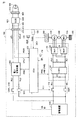
図1は、外部充電および外部給電が可能なハイブリッド車両の全体ブロック図の例である。図1を参照して、車両100は、蓄電装置110と、システムメインリレー(System Main Relay:SMR)115と、駆動装置であるPCU(Power Control Unit)120と、モータジェネレータ130,135と、動力伝達ギヤ140と、駆動輪150と、内燃機関であるエンジン160と、制御装置であるECU(Electronic Control Unit)300とを備える。PCU120は、コンバータ121と、インバータ122,123と、コンデンサC1,C2とを含む。
[Description of vehicle system]
FIG. 1 is an example of an overall block diagram of a hybrid vehicle capable of external charging and external power feeding. Referring to FIG. 1,
蓄電装置110は、充放電可能に構成された電力貯蔵要素である。蓄電装置110は、たとえば、リチウムイオン電池、ニッケル水素電池または鉛蓄電池などの二次電池、あるいは電気二重層キャパシタなどの蓄電素子を含んで構成される。
The
蓄電装置110は、電力線PL1,NL1を介してPCU120に接続される。そして、蓄電装置110は、車両100の駆動力を発生させるための電力をPCU120に供給する。また、蓄電装置110は、モータジェネレータ130、135で発電された電力を蓄電する。蓄電装置110の出力はたとえば200V程度である。
蓄電装置110は、いずれも図示しないが電圧センサおよび電流センサを含み、これらのセンサによって検出された、蓄電装置110の電圧VBおよび電流IBをECU300へ出力する。
Although not shown,
SMR115は、蓄電装置110の正極端と電力線PL1とに接続されるリレー、および蓄電装置110の負極端と電力線NL1とに接続されるリレーを含む。SMR115は、ECU300からの制御信号SE1に基づいて、蓄電装置110とPCU120との間で電力の供給と遮断とを切換える。
SMR 115 includes a relay connected to the positive end of
コンバータ121は、ECU300からの制御信号PWCに基づいて、電力線PL1,NL1と電力線PL2,電力線NL1との間で電圧変換を行なう。
Converter 121 performs voltage conversion between power lines PL1, NL1 and power lines PL2, NL1 based on control signal PWC from
インバータ122,123は、電力線PL2および電力線NL1に並列に接続される。インバータ122,123は、ECU300からの制御信号PWI1,PWI2にそれぞれ基づいて、コンバータ121から供給される直流電力を交流電力に変換し、モータジェネレータ130,135をそれぞれ駆動する。
コンデンサC1は、電力線PL1および電力線NL1の間に設けられ、電力線PL1および電力線NL1間の電圧変動を減少させる。また、コンデンサC2は、電力線PL2および電力線NL1の間に設けられ、電力線PL2および電力線NL1間の電圧変動を減少させる。 Capacitor C1 is provided between power line PL1 and power line NL1, and reduces voltage fluctuation between power line PL1 and power line NL1. Capacitor C2 is provided between power line PL2 and power line NL1, and reduces voltage fluctuation between power line PL2 and power line NL1.
モータジェネレータ130,135は交流回転電機であり、たとえば、永久磁石が埋設されたロータを備える永久磁石型同期電動機である。
モータジェネレータ130,135の出力トルクは、減速機や動力分割機構を含んで構成される動力伝達ギヤ140を介して駆動輪150に伝達されて、車両100を走行させる。モータジェネレータ130,135は、車両100の回生制動動作時には、駆動輪150の回転力によって発電することができる。そして、その発電電力は、PCU120によって蓄電装置110の充電電力に変換される。
The output torque of
また、モータジェネレータ130,135は動力伝達ギヤ140を介してエンジン160とも結合される。そして、ECU300により、モータジェネレータ130,135およびエンジン160が協調的に動作されて必要な車両駆動力が発生される。さらに、モータジェネレータ130,135は、エンジン160の回転により発電が可能であり、この発電電力を用いて蓄電装置110を充電することができる。なお、本実施の形態においては、モータジェネレータ135を専ら駆動輪150を駆動するための電動機として用い、モータジェネレータ130を専らエンジン160により駆動される発電機として用いるものとする。エンジン160は、制御信号DRVを用いてECU300により制御される。
なお、図1においては、モータジェネレータが2つ設けられる構成が例として示されるが、モータジェネレータの数はこれに限定されず、モータジェネレータが1つの場合、あるいは2つより多くのモータジェネレータを設ける構成としてもよい。 In FIG. 1, a configuration in which two motor generators are provided is shown as an example. However, the number of motor generators is not limited to this, and the number of motor generators is one, or more than two motor generators are provided. It is good also as a structure.
車両100は、外部電源500からの電力によって蓄電装置110を充電するための構成として、電力変換装置200と、充電リレーCHR210と、接続部であるインレット220とを含む。
インレット220には、充電ケーブル400の充電コネクタ410が接続される。そして、外部電源500からの電力が、充電ケーブル400を介して車両100に伝達される。
A charging
充電ケーブル400は、充電コネクタ410に加えて、外部電源500のコンセント510に接続するためのプラグ420と、充電コネクタ410およびプラグ420とを接続するケーブル部440とを含む。ケーブル部440には、外部電源500からの電力の供給および遮断を切換えるための充電回路遮断装置(以下、CCID(Charging Circuit Interrupt Device)とも称する。)430が介挿される。
In addition to charging
充電コネクタ410がインレット220に接続されると、接続状態を示す接続検知信号PISWがECU300に出力される。ECU300は、この接続検知信号PISWを受けることによって充電ケーブル400がインレット220に接続されたことを認識する。
When charging
また、充電コネクタ410がインレット220に接続されると、CCID430は、パイロット信号CPLTをECU300に出力する。パイロット信号CPLTは、たとえば、所定の周期で発振するパルス信号である。ECU300は、このパイロット信号CPLTのデューティおよび電圧に基づいて、充電ケーブル400の電流容量を認識したり、充電動作の実行/停止を制御する。
When charging
電力変換装置200は、電力線ACL1,ACL2を介して、インレット220に接続される。また、電力変換装置200は、CHR210を介して、電力線PL2および電力線NL2によって蓄電装置110に接続される。
電力変換装置200は、ECU300からの制御信号PWDによって制御され、インレット220から供給される交流電力を、蓄電装置110の充電電力に変換する。また、後述するように、電力変換装置200は、蓄電装置110からの直流電力またはモータジェネレータ130,135により発電されてPCU120で変換された直流電力を交流電力に変換して、車両外部へ給電することも可能である。電力変換装置200は、充電および給電の双方向の電力変換が可能な1つの装置であってもよいし、充電用の装置および給電用の装置を個別の装置として含むものであってもよい。
CHR210は、ECU300からの制御信号SE2によって制御され、電力変換装置200と蓄電装置110との間の電力の供給と遮断とを切換える。
車両100から外部給電を行なう場合には、図2に示すように、充電ケーブル400の充電コネクタ410と同一の形状の接続部を有する給電用コネクタ410Aがインレット220に接続される。給電用コネクタ410Aは、インレット220と接続される接続部とは反対の端部に、外部機器である電気機器700の電源プラグ710を接続することが可能に構成される。なお、図2のように、延長ケーブル750を用いることで車両100から離れた場所で電気機器700を使用することができる。
When external power feeding is performed from the
給電用コネクタ410Aは、インレット220に接続されると、充電ケーブル400と同様に接続検知信号PISWを出力するように構成される。ただし、給電用コネクタ410Aから出力される接続検知信号PISWの電圧は、充電コネクタ410から出力される接続検知信号PISWの電圧とは異なる電圧値となるように設定される。このようにすることによって、ECU300は、接続検知信号PISWの電圧を検出することによって、外部充電を行なうか、あるいは外部給電を行なうかを認識することができる。なお、外部充電と外部給電との区別ができれば、電圧値に限らず、たとえば電流値や発振周波数などを変化させるようにしてもよい。
When connected to
再び図1を参照して、車両100は、切換スイッチ170と、雨滴検知装置180と、通知部190とをさらに備える。
Referring again to FIG. 1,
雨滴検知装置180(以下、「雨滴センサ」とも称する。)は、降雨の有無を判定するための装置であり、たとえば、降雨時に自動的にワイパーを作動させるために用いられる。雨滴センサ180は、降雨の有無を示す信号RAINをECU300に出する。なお、後述するように、ECU300は、外部給電中に、雨滴センサ180からの信号RAINにより降雨が検出されると、外部給電を制限する外部給電制限制御を実行する。
The raindrop detection device 180 (hereinafter also referred to as “raindrop sensor”) is a device for determining the presence or absence of rain, and is used, for example, to automatically operate a wiper during rain.
切換スイッチ170は、この降雨時の外部給電制限制御の有効と無効とを切換えるためのスイッチであり、ユーザの操作により選択される。切換スイッチ170は、ユーザによる選択信号SELをECU300に出力する。
The
通知部190は、ユーザに対して異常等の各種情報を通知する。通知部190としては、チャイムやブザーあるいはボイスアナウンスのように聴覚的にユーザに通知するものであってもよいし、ランプなどの視覚的に通知するものであってもよい。通知部190として、クラクションやヘッドライトなどを用いることも可能である。また、通知部190は、ユーザの携帯端末に対して無線で情報を送信して通知するための通信部を含んでもよい。
The
ECU300は、いずれも図1には図示しないがCPU(Central Processing Unit)、記憶装置および入出力バッファを含み、各センサ等からの信号の入力や各機器への制御信号の出力を行なうとともに、蓄電装置110および車両100の各機器の制御を行なう。なお、これらの制御については、ソフトウェアによる処理に限られず、専用のハードウェア(電子回路)で処理することも可能である。
Although not shown in FIG. 1,
ECU300は、蓄電装置110からの電圧VBおよび電流IBの検出値に基づいて、蓄電装置110の充電状態SOC(State of Charge)を演算する。
ECU300は、充電ケーブル400の充電コネクタ410、および給電用コネクタ410Aから接続検知信号PISWを受ける。ECU300は、接続検知信号PISWに基づいてインレット220に接続されたコネクタの種類を判断し、外部充電を行なうか外部給電を行なうかを判定する。
なお、図1においては、ECU300として1つの制御装置を設ける構成としているが、たとえば、PCU120用の制御装置や蓄電装置110用の制御装置などのように、機能ごとまたは制御対象機器ごとに個別の制御装置を設ける構成としてもよい。
In FIG. 1, one control device is provided as the
[外部給電制限制御の説明]
図2のように、給電用コネクタ410Aを用いて屋外に設置された電気機器700に対して外部給電を行なっている状態において、天候の変化によって降雨(降雪も含む)が生じた場合を考える。このとき、使用する電気機器700が、屋外での使用に適した防水性,防沫性を有している場合には、雨等に濡れた状態で使用しても特に差支えはない。しかしながら、主に屋内での使用を目的とした機器が屋外で使用される場合に、雨等によって濡れた状態になると、電気機器700の筐体内に水が浸入して電気回路部が濡れてしまったり、電源プラグ710の端子部分が濡れてしまったりすることによって、電力または信号の伝達経路における絶縁が低下してしまい、地絡や短絡が生じる可能性がある。これによって、電力伝達経路に定格以上の電流が流れてしまい、機器の破損や故障を招くおそれがある。
[Description of external power supply restriction control]
Consider the case where rainfall (including snowfall) occurs due to a change in weather in a state where external power is supplied to the
そのため、本実施の形態においては、外部給電を実施している間に、車両において降雨を検出した場合には、外部給電動作を制限することによって、給電対象の電気機器が雨等に濡れた状態のままで使用されることを抑制する。これによって、電気機器および車両の破損や故障の発生を防止することができる。 Therefore, in the present embodiment, when rain is detected in the vehicle while external power feeding is being performed, the electric power supply target is wetted by rain or the like by restricting the external power feeding operation. Suppressing being used as it is. As a result, it is possible to prevent electrical equipment and vehicles from being damaged or malfunctioning.
なお、外部給電を行なっている場合であっても、使用される電気機器が十分な防水性を有している場合や、適切な防水対策が施されていたり、テントや軒下などの雨がかからない場所で使用される場合においては、車両で降雨が検出されたとしても、外部給電を継続して差支えない。そのため、当該外部給電動作の制限を行なうか否かを、ユーザにより設定可能とすることが好ましい。 Even when external power is being supplied, if the electrical equipment used is sufficiently waterproof, appropriate waterproofing measures have been taken, and rain such as under tents or eaves is not applied. When used in a place, even if rain is detected in the vehicle, external power feeding can be continued. Therefore, it is preferable that the user can set whether or not to limit the external power supply operation.
図3は、本実施の形態において、ECU300で実行される降雨時の外部給電制限制御を説明するためのフローチャートである。図3および後述する図4のフローチャートは、ECU300に予め格納されたプログラムが所定周期で実行されることによって処理が実現される。あるいは、一部のステップについては、専用のハードウェア(電子回路)を構築して処理を実現することも可能である。
FIG. 3 is a flowchart for explaining the external power supply restriction control at the time of rainfall executed by
図1および図3を参照して、ECU300は、接続検知信号PISWによって、給電用コネクタ410A(図2)がインレット220に接続されたことを検知すると、ステップ(以下、ステップをSと略す。)100において、ユーザにより給電スイッチ(図示せず)がオンとされて給電開始が指示されたか否かを判定する。給電スイッチは、車内のコンソール上あるいはナビゲーションシステムのような操作表示用の液晶パネルなどに組み込まれてもよいし、給電用コネクタ410Aに個別の開始ボタンなどを設けるようにしてもよい。
Referring to FIGS. 1 and 3,
給電開始が指示されていない場合(S100にてNO)は、給電が実行されないので、ECU300は処理を終了する。一方、給電開始が指示された場合(S100にてYES)は、処理がS110に進められて、ECU300は、ユーザにより設定された切換スイッチ170からの選択信号SELによって、降雨時の給電制限機能が有効とされているか否かを判定する。
If power supply start is not instructed (NO in S100), power supply is not executed, and
給電制限機能が無効とされている場合(S110にてNO)は、S120,S130がスキップされて、処理がS140に進められる。 If the power supply restriction function is disabled (NO in S110), S120 and S130 are skipped, and the process proceeds to S140.
給電制限機能が有効とされている場合(S110にてYES)は、処理がS120に進められ、ECU300は雨滴センサ180を作動させる。そして、ECU300は、S190にて、雨滴センサ180によって雨滴が検出されたか否かを判定する。
If the power supply restriction function is enabled (YES in S110), the process proceeds to S120, and
雨滴が検出された場合(S130にてYES)は、ECU300は、処理をS150に進めて、給電動作を実行せずに処理を終了する。一方、雨滴が検出されなかった場合(S130にてNO)は、処理がS140に進められる。
If raindrops are detected (YES in S130),
S140においては、ECU300は、雨滴検出以外の他の給電停止条件が成立したか否かを判定する。他の給電停止条件は、たとえば、蓄電装置110のSOCが低下したり、エンジンを160を駆動するための燃料が不足して発電が行なえなくなったりして給電自体ができなくなった場合、車両100に異常が生じた場合、給電用コネクタ410Aが意図せずに引き抜かれてしまった場合などが含まれる。
In S140,
他の給電停止条件が成立した場合(S140にてYES)は、処理がS150に進められて、外部給電を実行中であれば給電動作を停止し、給電動作がまだ行なわれていない場合には給電動作を開始せずに処理を終了する。 If another power supply stop condition is satisfied (YES in S140), the process proceeds to S150, and if the external power supply is being executed, the power supply operation is stopped, and if the power supply operation has not been performed yet. The process ends without starting the power feeding operation.
他の給電停止条件が成立していない場合(S140にてNO)は、外部給電を行なうことができる状態であるので、ECU300は、処理をS145に進めて、現在給電動作が実行中であるか否かを判定する。現在給電動作が実行中でない場合(S145にてNO)は、処理がS146に進められて、ECU300は給電動作を開始し、その後処理をS110に戻す。一方、現在給電動作が実行中である場合(S145にてYES)は、ECU300は給電動作を継続しつつ、処理をS110に戻す。
If other power supply stop conditions are not satisfied (NO in S140), the external power supply can be performed. Therefore,
処理がS110に戻されると、ECU300は、外部給電を実行しながら、雨滴センサ180による降雨の有無、および他の給電停止条件が成立したか否かをさらに判定する(S130,S140)。そして、雨滴の検知あるいは他の停止条件が成立した場合(S130,S140にてYES)には給電動作を停止し(S150)、これらの停止条件が成立していない場合には給電動作を継続する。
When the process returns to S110,
なお、図3のフローチャートにおいては、雨滴が検出された場合に即座に給電動作を停止する場合を例として説明したが、雨滴が検出されないときよりも給電電力を低下した状態にするようにしてもよいし、給電電力を徐々にゼロまで低下させてもよい。 In the flowchart of FIG. 3, the case where the power feeding operation is immediately stopped when raindrops are detected has been described as an example. However, the power feeding power may be made lower than when no raindrops are detected. Alternatively, the feed power may be gradually reduced to zero.
以上のような処理に従って制御を行なうことによって、外部給電を実行中に天候が変化して降雨または降雪が生じた場合に外部給電が制限されるので、電気機器が濡れて絶縁低下した状態で継続して使用されることが抑制される。これによって、電気機器および車両の破損および故障を抑制することが可能となる。 By performing control according to the above process, external power supply is restricted when the weather changes and rain or snowfall occurs while external power supply is being executed. To be used. As a result, it is possible to suppress damage and failure of the electric equipment and the vehicle.
(変形例)
図3で説明した処理においては、外部給電中に雨滴が検知されると、ECUにより即座に給電が停止される場合を例として説明したが、使用する電気機器によっては所定の手順で停止させることが必要な場合や、誤って雨滴センサに水をかけて誤作動させてしまった場合など、即座に給電が停止されるとかえって不都合が生じてしまう場合があり得る。
(Modification)
In the process described with reference to FIG. 3, the case where the power supply is immediately stopped by the ECU when raindrops are detected during external power supply has been described as an example. However, depending on the electric equipment used, the process may be stopped in a predetermined procedure. When the power supply is immediately stopped, such as when the raindrop sensor is necessary or when the raindrop sensor is accidentally operated by water, there is a possibility that inconvenience may occur.
そこで、図4のフローチャートに示す変形例においては、雨滴センサにより雨滴が検出された場合でも即座に給電を停止せず、一定期間給電を継続しながらユーザに雨滴を検出したことを通知し、一定期間が経過した後に給電を停止する。 Therefore, in the modification shown in the flowchart of FIG. 4, even when a raindrop is detected by the raindrop sensor, the power supply is not stopped immediately, and the user is notified that the raindrop has been detected while continuing the power supply for a certain period. Power supply is stopped after the period has elapsed.
図4は、ECU300で実行される降雨時の外部給電制限制御の変形例を説明するためのフローチャートである。図4は、図3のフローチャートに、ステップS135,S136が追加されたものとなっている。図4において、図3と重複するステップの説明は繰り返さない。
FIG. 4 is a flowchart for explaining a modified example of the external power supply restriction control at the time of rainfall executed by
図1および図4を参照して、外部給電を実行中に雨滴センサ180によって雨滴が検出されると(S130にてYES)、処理がS135に進められて、ECU300は、ユーザに対して、通知部190を用いて雨滴が検出された旨の通知を行なう。そして、ECU300は、S136にて、予め定められた一定期間が経過したか否かを判定する。これにより、ECU300は、ユーザに対して、この一定期間中に、電気機器の停止あるいは適切な防水措置を実施することを促す。
Referring to FIGS. 1 and 4, if a raindrop is detected by
一定期間が経過していない場合(S136にてNO)は、処理がS110に戻されて、ECU300は一定期間が経過するまでユーザへの通知を継続する。一方、一定期間が経過した場合(S136にてYES)は、処理がS150に進められて、ECU300は給電動作を停止する。
If the certain period has not elapsed (NO in S136), the process returns to S110, and
なお、たとえば、一定期間が経過するのを待っている間に適切な防水措置が施された場合や誤作動であることが明らかである場合に、ユーザにより切換スイッチ170が操作されて降雨時の外部給電制限機能が無効とされると(S110にてNO)、ECU300はユーザへの通知を停止して給電動作を継続する。この場合は、他の給電停止条件が成立するまで給電動作が継続される。
In addition, for example, when appropriate waterproofing measures are taken while waiting for a certain period of time or when it is clear that a malfunction has occurred, the user operates the
以上の処理に従って制御を行なうことによって、外部給電中に降雨が検出された場合に、ユーザへの通知がなされて、それに応じてユーザに適切な処置を行なわせることが可能となる。そして、所定期間経過後に外部給電を停止することで、電気機器が雨に濡れたままの状態で継続して動作されることを防止し、電気機器および車両の破損および故障を抑制することができる。 By performing control according to the above processing, when rain is detected during external power feeding, the user is notified and appropriate measures can be taken by the user accordingly. And by stopping the external power supply after the lapse of a predetermined period, it is possible to prevent the electric device from being operated continuously in the state of being wet with rain, and to suppress the damage and failure of the electric device and the vehicle. .
以下に、本発明を、図面の各要素と対応させて要約する。
車両100は、車載の蓄電装置110からの電力をインレット220を通して車両外部の電気機器700に供給可能である。車両100は、降雨を検知するように構成された雨滴センサ180と、雨滴センサ180により降雨が検知されたことに応答して、蓄電装置110から電気機器700への電力供給を制限するECU300とをさらに備える。
The invention is summarized below in correspondence with the elements of the drawing.
The
ECU300は、電気機器700への電力供給中に降雨が検知された場合は、所定期間が経過したことに応答して、電気機器700への電力供給を停止する。
When rain is detected during power supply to
車両100は、電気機器700への電力供給中に降雨が検知されたことを通知するための通知部190をさらに備える。
ECU300は、通知部190による通知の開始から所定期間が経過したことに応答して、電気機器700への電力供給を停止する。
ECU300は、降雨が検知されたことに応答して車両100からの電力供給を停止するか否かを、ユーザからの設定に応じて切換える。
車両100は、蓄電装置110からの電力を変換してインレット220へ供給する電力変換装置200をさらに備える。ECU300は、電気機器700への電力供給中に降雨が検知されたことに応答して、電力変換装置200を停止することによって、電気機器700への電力供給を停止する。
車両100は、充電ケーブル400を介して供給される外部電源500からの電力を用いて蓄電装置110を充電することが可能である。充電ケーブル400はインレット220に接続可能である。
電気機器700は、給電用コネクタ410Aを介してインレット220に電気的に接続される。ECU300は、インレット220に給電用コネクタ410Aが取り付けられたことに応答して、電気機器700への電力の供給を許可する。
The
車両100は、エンジン160と、エンジン160により駆動されることによって電力を発生することが可能に構成されたモータジェネレータ130とをさらに備える。ECU300は、蓄電装置110からの電力およびモータジェネレータ130からの電力の少なくともいずれか一方の電力を電気機器700へ供給する。
なお、本実施の形態における「雨滴検知装置(雨滴センサ)180」は、本発明における「検知部」の一例である。 The “raindrop detection device (raindrop sensor) 180” in the present embodiment is an example of the “detection unit” in the present invention.
今回開示された実施の形態はすべての点で例示であって制限的なものではないと考えられるべきである。本発明の範囲は上記した説明ではなく、特許請求の範囲によって示され、特許請求の範囲と均等の意味および範囲内でのすべての変更が含まれることが意図される。 The embodiment disclosed this time should be considered as illustrative in all points and not restrictive. The scope of the present invention is defined by the terms of the claims, rather than the description above, and is intended to include any modifications within the scope and meaning equivalent to the terms of the claims.
100 車両、110 蓄電装置、115 SMR、120 PCU、121 コンバータ、122,123 インバータ、130,135 モータジェネレータ、140 動力伝達ギヤ、150 駆動輪、160 エンジン、170 切換スイッチ、180 雨滴検知装置、190 通知部、200 電力変換装置、210 CHR、220 インレット、300 ECU、400 充電ケーブル、410 充電コネクタ、410A 給電用コネクタ、420 プラグ、440 ケーブル部、500 外部電源、510 コンセント、700 電気機器、710 電源プラグ、750 延長ケーブル、ACL1,ACL2,NL1,NL2,PL1,PL2 電力線、C1,C2 コンデンサ。
100 vehicle, 110 power storage device, 115 SMR, 120 PCU, 121 converter, 122, 123 inverter, 130, 135 motor generator, 140 power transmission gear, 150 drive wheel, 160 engine, 170 changeover switch, 180 raindrop detection device, 190 notification Part, 200 power converter, 210 CHR, 220 inlet, 300 ECU, 400 charging cable, 410 charging connector, 410A power supply connector, 420 plug, 440 cable part, 500 external power supply, 510 outlet, 700 electrical equipment, 710
Claims (9)
降雨を検知するように構成された検知部と、
前記検知部により降雨が検知されると、前記蓄電装置から前記外部機器への電力供給を制限する制御装置とを備える、車両。 A vehicle capable of supplying electric power from an in-vehicle power storage device to an external device through a connection part,
A detector configured to detect rainfall;
A vehicle comprising: a control device that restricts power supply from the power storage device to the external device when rain is detected by the detection unit.
前記外部機器への電力供給中に降雨が検知されると、前記制御装置は、前記電力変換装置を停止することによって前記外部機器への電力供給を停止する、請求項1に記載の車両。 It further comprises a power conversion device that converts power from the power storage device and supplies the power to the connection unit,
2. The vehicle according to claim 1, wherein, when rain is detected during power supply to the external device, the control device stops power supply to the external device by stopping the power conversion device.
前記接続部は、前記充電ケーブルが接続可能に構成されるインレットである、請求項1に記載の車両。 The vehicle is capable of charging the power storage device using electric power from an external power source supplied via a charging cable,
The vehicle according to claim 1, wherein the connection portion is an inlet configured to be connectable to the charging cable.
前記接続部に前記電力取出装置が取り付けられると、前記制御装置は前記外部機器への電力の供給を許可する、請求項1に記載の車両。 The external device is electrically connected to the connecting portion via a power extraction device,
The vehicle according to claim 1, wherein when the power extraction device is attached to the connecting portion, the control device permits supply of power to the external device.
前記内燃機関によって駆動されることによって電力を発生することが可能に構成された発電機とをさらに備え、
前記制御装置は、前記蓄電装置からの電力および前記発電機からの電力の少なくともいずれか一方の電力を前記外部機器へ供給する、請求項1に記載の車両。 An internal combustion engine;
A generator configured to generate electric power when driven by the internal combustion engine,
The vehicle according to claim 1, wherein the control device supplies at least one of electric power from the power storage device and electric power from the generator to the external device.
Priority Applications (1)
| Application Number | Priority Date | Filing Date | Title |
|---|---|---|---|
| JP2013060013A JP2014187771A (en) | 2013-03-22 | 2013-03-22 | Vehicle |
Applications Claiming Priority (1)
| Application Number | Priority Date | Filing Date | Title |
|---|---|---|---|
| JP2013060013A JP2014187771A (en) | 2013-03-22 | 2013-03-22 | Vehicle |
Publications (1)
| Publication Number | Publication Date |
|---|---|
| JP2014187771A true JP2014187771A (en) | 2014-10-02 |
Family
ID=51834798
Family Applications (1)
| Application Number | Title | Priority Date | Filing Date |
|---|---|---|---|
| JP2013060013A Pending JP2014187771A (en) | 2013-03-22 | 2013-03-22 | Vehicle |
Country Status (1)
| Country | Link |
|---|---|
| JP (1) | JP2014187771A (en) |
Cited By (1)
| Publication number | Priority date | Publication date | Assignee | Title |
|---|---|---|---|---|
| JP2020068633A (en) * | 2018-10-26 | 2020-04-30 | トヨタ自動車株式会社 | Charging control device, charging system, and vehicle |
Citations (4)
| Publication number | Priority date | Publication date | Assignee | Title |
|---|---|---|---|---|
| JPH10290529A (en) * | 1997-04-14 | 1998-10-27 | Denso Corp | Power unit for electric automobile |
| JP2010098845A (en) * | 2008-10-16 | 2010-04-30 | Toyota Motor Corp | Charge controller of vehicle, and vehicle |
| JP2011244667A (en) * | 2010-05-21 | 2011-12-01 | Autonetworks Technologies Ltd | Vehicle charging device |
| JP2013051772A (en) * | 2011-08-30 | 2013-03-14 | Toyota Motor Corp | Power supply connector, vehicle and control method therefor |
-
2013
- 2013-03-22 JP JP2013060013A patent/JP2014187771A/en active Pending
Patent Citations (4)
| Publication number | Priority date | Publication date | Assignee | Title |
|---|---|---|---|---|
| JPH10290529A (en) * | 1997-04-14 | 1998-10-27 | Denso Corp | Power unit for electric automobile |
| JP2010098845A (en) * | 2008-10-16 | 2010-04-30 | Toyota Motor Corp | Charge controller of vehicle, and vehicle |
| JP2011244667A (en) * | 2010-05-21 | 2011-12-01 | Autonetworks Technologies Ltd | Vehicle charging device |
| JP2013051772A (en) * | 2011-08-30 | 2013-03-14 | Toyota Motor Corp | Power supply connector, vehicle and control method therefor |
Cited By (5)
| Publication number | Priority date | Publication date | Assignee | Title |
|---|---|---|---|---|
| JP2020068633A (en) * | 2018-10-26 | 2020-04-30 | トヨタ自動車株式会社 | Charging control device, charging system, and vehicle |
| CN111098726A (en) * | 2018-10-26 | 2020-05-05 | 丰田自动车株式会社 | Charging controller, charging system and vehicle |
| JP7063234B2 (en) | 2018-10-26 | 2022-05-09 | トヨタ自動車株式会社 | Charge control device, charging system, and vehicle |
| US11420526B2 (en) | 2018-10-26 | 2022-08-23 | Toyota Jidosha Kabushiki Kaisha | Charge controller, charging system, and vehicle |
| CN111098726B (en) * | 2018-10-26 | 2024-02-23 | 丰田自动车株式会社 | Charging controller, charging system and vehicle |
Similar Documents
| Publication | Publication Date | Title |
|---|---|---|
| US9434257B2 (en) | Power supply connector, vehicle and control method for vehicle | |
| JP6156484B2 (en) | vehicle | |
| US9614379B2 (en) | Adapter, and vehicle and method for performing power feeding using adapter | |
| EP3036128B1 (en) | Charging system, vehicle, and charging facility | |
| JP5601385B2 (en) | Adapter, vehicle including the same, and vehicle control method | |
| US9090169B2 (en) | Adapter and vehicle for performing power feeding using adapter | |
| KR101150911B1 (en) | Charging control device for vehicle | |
| US10000137B2 (en) | Hybrid vehicle with means for disconnection of a depleted auxiliary battery in order to allow for more rapid main battery charging | |
| JP6044460B2 (en) | Vehicle power supply | |
| EP2752331A1 (en) | Vehicle, charging system, and method for controlling vehicle | |
| JPWO2013057775A1 (en) | Power supply connector, vehicle, and method for recognizing power supply connector | |
| JP2010098845A (en) | Charge controller of vehicle, and vehicle | |
| WO2015071721A1 (en) | Charging and discharging system and vehicle used therein | |
| WO2011132054A2 (en) | Charging apparatus and vehicle equipped with the charging apparatus | |
| JP2012249384A (en) | Vehicle | |
| WO2012164681A1 (en) | Vehicle and method for controlling vehicle | |
| JP2014187771A (en) | Vehicle | |
| JP5994718B2 (en) | Vehicle and power supply system | |
| JP5682509B2 (en) | Vehicle charging device, charging line communication system | |
| JP5929813B2 (en) | Electric power take-out device | |
| JP2011239556A (en) | Vehicle |
Legal Events
| Date | Code | Title | Description |
|---|---|---|---|
| A621 | Written request for application examination |
Free format text: JAPANESE INTERMEDIATE CODE: A621 Effective date: 20150612 |
|
| A977 | Report on retrieval |
Free format text: JAPANESE INTERMEDIATE CODE: A971007 Effective date: 20160113 |
|
| A131 | Notification of reasons for refusal |
Free format text: JAPANESE INTERMEDIATE CODE: A131 Effective date: 20160119 |
|
| A02 | Decision of refusal |
Free format text: JAPANESE INTERMEDIATE CODE: A02 Effective date: 20160524 |