JP2014155674A - Radiographic device and control method for radiographic device - Google Patents
Radiographic device and control method for radiographic device Download PDFInfo
- Publication number
- JP2014155674A JP2014155674A JP2013029436A JP2013029436A JP2014155674A JP 2014155674 A JP2014155674 A JP 2014155674A JP 2013029436 A JP2013029436 A JP 2013029436A JP 2013029436 A JP2013029436 A JP 2013029436A JP 2014155674 A JP2014155674 A JP 2014155674A
- Authority
- JP
- Japan
- Prior art keywords
- imaging
- radiation
- unit
- radiation imaging
- rotation
- Prior art date
- Legal status (The legal status is an assumption and is not a legal conclusion. Google has not performed a legal analysis and makes no representation as to the accuracy of the status listed.)
- Pending
Links
- 238000000034 method Methods 0.000 title claims description 5
- 238000003384 imaging method Methods 0.000 claims abstract description 265
- 238000001514 detection method Methods 0.000 claims abstract description 56
- 230000005855 radiation Effects 0.000 claims description 175
- 230000007246 mechanism Effects 0.000 description 19
- 238000010586 diagram Methods 0.000 description 11
- 238000002601 radiography Methods 0.000 description 11
- 239000000758 substrate Substances 0.000 description 7
- 239000011521 glass Substances 0.000 description 6
- OAICVXFJPJFONN-UHFFFAOYSA-N Phosphorus Chemical compound [P] OAICVXFJPJFONN-UHFFFAOYSA-N 0.000 description 2
- 238000013459 approach Methods 0.000 description 2
- 230000008901 benefit Effects 0.000 description 2
- 230000008859 change Effects 0.000 description 2
- 238000006243 chemical reaction Methods 0.000 description 2
- 230000003028 elevating effect Effects 0.000 description 2
- 210000003141 lower extremity Anatomy 0.000 description 2
- 230000002685 pulmonary effect Effects 0.000 description 2
- 210000001015 abdomen Anatomy 0.000 description 1
- 230000005540 biological transmission Effects 0.000 description 1
- 239000004918 carbon fiber reinforced polymer Substances 0.000 description 1
- 210000000038 chest Anatomy 0.000 description 1
- 239000000470 constituent Substances 0.000 description 1
- 230000000694 effects Effects 0.000 description 1
- 210000003128 head Anatomy 0.000 description 1
- 210000004072 lung Anatomy 0.000 description 1
- 238000012986 modification Methods 0.000 description 1
- 230000004048 modification Effects 0.000 description 1
- 230000003287 optical effect Effects 0.000 description 1
- 230000008569 process Effects 0.000 description 1
- 238000012545 processing Methods 0.000 description 1
- 238000012360 testing method Methods 0.000 description 1
Images


Classifications
-
- G—PHYSICS
- G03—PHOTOGRAPHY; CINEMATOGRAPHY; ANALOGOUS TECHNIQUES USING WAVES OTHER THAN OPTICAL WAVES; ELECTROGRAPHY; HOLOGRAPHY
- G03B—APPARATUS OR ARRANGEMENTS FOR TAKING PHOTOGRAPHS OR FOR PROJECTING OR VIEWING THEM; APPARATUS OR ARRANGEMENTS EMPLOYING ANALOGOUS TECHNIQUES USING WAVES OTHER THAN OPTICAL WAVES; ACCESSORIES THEREFOR
- G03B42/00—Obtaining records using waves other than optical waves; Visualisation of such records by using optical means
-
- A—HUMAN NECESSITIES
- A61—MEDICAL OR VETERINARY SCIENCE; HYGIENE
- A61B—DIAGNOSIS; SURGERY; IDENTIFICATION
- A61B6/00—Apparatus or devices for radiation diagnosis; Apparatus or devices for radiation diagnosis combined with radiation therapy equipment
- A61B6/42—Arrangements for detecting radiation specially adapted for radiation diagnosis
- A61B6/4208—Arrangements for detecting radiation specially adapted for radiation diagnosis characterised by using a particular type of detector
- A61B6/4233—Arrangements for detecting radiation specially adapted for radiation diagnosis characterised by using a particular type of detector using matrix detectors
-
- A—HUMAN NECESSITIES
- A61—MEDICAL OR VETERINARY SCIENCE; HYGIENE
- A61B—DIAGNOSIS; SURGERY; IDENTIFICATION
- A61B6/00—Apparatus or devices for radiation diagnosis; Apparatus or devices for radiation diagnosis combined with radiation therapy equipment
- A61B6/44—Constructional features of apparatus for radiation diagnosis
- A61B6/4429—Constructional features of apparatus for radiation diagnosis related to the mounting of source units and detector units
- A61B6/4435—Constructional features of apparatus for radiation diagnosis related to the mounting of source units and detector units the source unit and the detector unit being coupled by a rigid structure
- A61B6/4441—Constructional features of apparatus for radiation diagnosis related to the mounting of source units and detector units the source unit and the detector unit being coupled by a rigid structure the rigid structure being a C-arm or U-arm
-
- A—HUMAN NECESSITIES
- A61—MEDICAL OR VETERINARY SCIENCE; HYGIENE
- A61B—DIAGNOSIS; SURGERY; IDENTIFICATION
- A61B6/00—Apparatus or devices for radiation diagnosis; Apparatus or devices for radiation diagnosis combined with radiation therapy equipment
- A61B6/54—Control of apparatus or devices for radiation diagnosis
- A61B6/547—Control of apparatus or devices for radiation diagnosis involving tracking of position of the device or parts of the device
Landscapes
- Health & Medical Sciences (AREA)
- Life Sciences & Earth Sciences (AREA)
- Engineering & Computer Science (AREA)
- Medical Informatics (AREA)
- Physics & Mathematics (AREA)
- Molecular Biology (AREA)
- High Energy & Nuclear Physics (AREA)
- Radiology & Medical Imaging (AREA)
- Surgery (AREA)
- Pathology (AREA)
- Nuclear Medicine, Radiotherapy & Molecular Imaging (AREA)
- Biomedical Technology (AREA)
- Heart & Thoracic Surgery (AREA)
- Biophysics (AREA)
- Optics & Photonics (AREA)
- Animal Behavior & Ethology (AREA)
- General Health & Medical Sciences (AREA)
- Public Health (AREA)
- Veterinary Medicine (AREA)
- Mathematical Physics (AREA)
- General Physics & Mathematics (AREA)
- Apparatus For Radiation Diagnosis (AREA)
- Spectroscopy & Molecular Physics (AREA)
Abstract
Description
本発明は、放射線をその強度に応じて電気信号に変換する放射線検出パネルを用いた放射線撮影装置および放射線撮影装置の制御方法に関するものである。 The present invention relates to a radiation imaging apparatus using a radiation detection panel that converts radiation into an electrical signal according to its intensity, and a method for controlling the radiation imaging apparatus.
近年、蛍光体と大面積固体撮像素子を密着させた放射線検出パネルを使用し、放射線像を直接デジタル化するデジタル放射線撮影装置が実用化され、従来のアナログ撮影装置に置き換わり、広く使われるようになってきた。放射線検出パネルを使用したデジタル放射線撮影装置によれば、放射線像を瞬時にデジタル情報として得ることができ、技師による撮影作業の省力化、医師による読影の効率化等、多くの利点が得られている。 In recent years, a digital radiation imaging device that directly digitizes a radiation image using a radiation detection panel in which a phosphor and a large-area solid-state imaging device are in close contact with each other has been put into practical use, and has been replaced with a conventional analog imaging device so that it is widely used. It has become. According to a digital radiography apparatus using a radiation detection panel, a radiographic image can be obtained instantly as digital information, and many advantages such as labor saving of imaging work by an engineer and efficiency of interpretation by a doctor are obtained. Yes.
このようなデジタル放射線撮影装置の画像取得部である放射線撮像部の内部構造としては、筐体内に、放射線検出パネルが支持部材に保持された状態で内蔵された構成が知られている(特許文献1参照)。 As an internal structure of a radiation imaging unit that is an image acquisition unit of such a digital radiography apparatus, a configuration in which a radiation detection panel is held in a support member is known (Patent Document). 1).
特許文献1の図1のように、X線像検出パネル(以下、放射線検出パネル)24の両端に、放射線検出パネル24を駆動する信号を送る為の、また、放射線検出パネル24で得られた信号を取り出す為のフレキシブル配線基板27(FPC)が接続されている。そして、放射線検出パネル24上の撮影領域の外側には、FPC27を接続する為の接続用電極26が設けられている。接続用電極26に接続されたFPC27は、放射線検出パネル24と筐体21の内壁との間を通り、後方に配置された回路基板28、29に接続されている。
As shown in FIG. 1 of
放射線検出パネル24における撮影領域は、接続用電極26の内側の領域となる。この為、筐体21の外壁から撮影領域までの間には、筐体側面の厚みと、筐体内壁とパネルとの間のFPCの配置スペースと、放射線検出パネル24上の接続用電極26が必要であり、有る程度の距離を有していた。 An imaging region in the radiation detection panel 24 is a region inside the connection electrode 26. For this reason, between the outer wall of the casing 21 and the imaging region, the thickness of the casing side surface, the space for arranging the FPC between the casing inner wall and the panel, and the connection electrode 26 on the radiation detection panel 24 are provided. It was necessary and had some distance.
一方、これらの放射線撮像部は、撮影目的に応じて立位スタンドや撮影台などに取り付けられ、撮影に供されている。また、放射線撮像部とX線管球部とを対向状態で保持する保持部を有し、保持部の位置を変更することにより、被検体を様々な方向から撮影を行うことが可能な撮影装置も提案されている(特許文献2参照:これを従来例1とする)。 On the other hand, these radiation imaging units are attached to a standing stand, an imaging stand or the like according to the imaging purpose, and are used for imaging. In addition, an imaging apparatus that has a holding unit that holds the radiation imaging unit and the X-ray tube unit in an opposed state, and can image the subject from various directions by changing the position of the holding unit. Has also been proposed (see Patent Document 2: this is referred to as Conventional Example 1).
特許文献2の撮影装置では、放射線撮像部を保持する保持部を移動させて、放射線撮像部の端部を被検体に近づけた状態で撮影を行うことが可能である。この場合、放射線入射面と平行な平面方向で、放射線撮像部の筐体の側面から撮影領域までの距離が短いことにより、被検部位に対してより接近した位置に放射線撮像部を配置することができる。ここで、筐体の側面から撮影領域までの距離が短い側面を狭額縁という。また、被検体から若干離して放射線撮像部を配置する場合には、狭額縁は、被検体と放射線撮像部との間により広く隙間を確保することができ、被検体にとっては、圧迫感を和らげることができる。
In the imaging apparatus of
図9は、立位スタンド1に放射線撮像部2を取り付けた図である。胸部単純撮影では、被検体Pは、放射線撮像部2の上部の側面に顎を載せた姿勢で撮影が行われる。放射線撮像部2の撮影領域をAで表すと、被検体Pの肺の上端(肺尖)まで撮影を行う為には、放射線撮像部2の上部の側面から撮影領域Aまでの距離L1が短いこと、即ち、上部が狭額縁となっていることが好ましい。(これを従来例2とする。)
また従来は、特許文献1の図3のように、放射線検出パネル24の4辺すべてにFPC27を配置していたが、近年、放射線検出パネルの改良により、FPCが接続されていない辺を設けた放射線検出パネルが開発されている。FPCが接続されていない放射線検出パネルの辺では、放射線検出パネルの端部に形成されていた接続用電極(例えば、特許文献1の図1の接続用電極26)が不要となる。更にFPCの配置スペースを必要としない為、筐体を狭額縁の構造に作り込むことが容易である。但し、FPCの接続をすべての辺について無くすことはできず、通常、駆動用FPCと読み出し用FPCを、放射線検出パネルの隣り合う2辺に配置したものが実用化されている。そして、このような放射線検出パネルを用いた場合、FPCが接続されていない辺に対応する筐体側面は、FPCが接続されている辺に対応する筐体側面より狭額縁となる。これにより、放射線検出パネルの4つの側面の内、額縁の長さが短い側面を有する放射線撮影部を提供できるようになった。
FIG. 9 is a diagram in which the
Conventionally, as shown in FIG. 3 of
また、狭額縁を有する放射線撮像部を提供する別の構成として、特許文献3では、放射線検出パネルを保持する内部構造体が筐体の内部で移動することにより狭額縁が作られる構成が示されている(これを従来例3とする)。
In addition, as another configuration for providing a radiation imaging unit having a narrow frame,
上記の従来例では、次のような課題がある。狭額縁を作り込んだ構造を考えた場合、直方体形状の筐体を有する放射線撮影部は、筐体の側面から有効撮影領域までの長さ(額縁長さ)が異なる側面を有する。 The above conventional example has the following problems. When considering a structure in which a narrow frame is formed, a radiation imaging unit having a rectangular parallelepiped housing has side surfaces with different lengths (frame lengths) from the side surface of the housing to the effective imaging region.
例えば、従来例1のようなCアームに取り付けた撮影装置では、額縁長さが異なる放射線撮像部については考慮されておらず、また、狭額縁を有効に利用した撮影手法についても想定されていない。 For example, in the imaging apparatus attached to the C-arm as in Conventional Example 1, the radiation imaging units having different frame lengths are not considered, and the imaging technique that effectively uses the narrow frame is not assumed. .
また、従来例2のような狭額縁の位置を上方に固定した放射線撮像部では、放射線検出パネルにおけるFPCの配置の関係上、下方も狭額縁に作り込むことが困難である。これにより、異なる撮影部位に対して、例えば、腰かけた状態で撮影するような場合、下方に狭額縁が必要な撮影形態に対しては、対応することができなかった。 In addition, in the radiation imaging unit in which the position of the narrow frame is fixed upward as in Conventional Example 2, it is difficult to make the lower part into the narrow frame because of the arrangement of the FPC in the radiation detection panel. As a result, for example, in the case of photographing in a sitting state with respect to different photographing parts, it has not been possible to cope with a photographing form that requires a narrow frame below.
一方、従来例3の構成においては、放射線検出パネルが筐体内部を移動することにより、狭額縁の位置を変更することができる。但し、前述のように、最大に移動した後に形成される狭額縁の長さは、筐体内部に収納する放射線検出パネルのFPCの接続状態に依存しており、筐体側面の場所により狭額縁の長さに差が生じる状況は、解決されていない。即ち、狭額縁を可能な限り有効に利用すること、すなわち、狭額縁を撮影条件に応じた方向に向けた撮影ができない。 On the other hand, in the configuration of Conventional Example 3, the position of the narrow frame can be changed by moving the radiation detection panel inside the housing. However, as described above, the length of the narrow frame formed after the maximum movement depends on the connection state of the FPC of the radiation detection panel housed in the housing, and the narrow frame depends on the location on the side of the housing. The situation in which there is a difference in length is not solved. That is, the narrow frame cannot be used as effectively as possible, that is, the narrow frame cannot be photographed in the direction corresponding to the photographing condition.
上記の課題を鑑み、本発明は、放射線撮像部の狭額縁を撮影条件に応じた方向に向けた撮影を容易に行うことができる放射線撮像技術の提供を目的とする。 In view of the above-described problems, an object of the present invention is to provide a radiation imaging technique that can easily perform imaging with a narrow frame of a radiation imaging unit directed in a direction according to imaging conditions.
上記目的を達成するための本発明の一つの側面に係る放射線撮影装置は、筐体と矩形の撮影領域を有する検出部とを有し、前記筐体の一つの側面から前記撮影領域までの距離が他の側面から前記撮影領域までの距離よりも短くなる前記筐体内の位置に前記検出部が配置されている放射線撮像部と、
前記撮影領域に対して交差する方向の回転軸を中心として前記放射線撮像部を回転する回転手段と、 前記撮影領域との距離が短い前記筐体の一つの側面を、撮影条件に応じた方向に向けるように、前記回転手段の回転を制御する制御手段と、
を有することを特徴とする。
In order to achieve the above object, a radiation imaging apparatus according to one aspect of the present invention includes a housing and a detection unit having a rectangular imaging region, and a distance from one side surface of the housing to the imaging region. A radiation imaging unit in which the detection unit is disposed at a position in the housing that is shorter than the distance from the other side surface to the imaging region;
Rotating means for rotating the radiation imaging unit around a rotation axis in a direction intersecting the imaging area, and one side surface of the housing having a short distance from the imaging area in a direction according to imaging conditions Control means for controlling the rotation of the rotating means,
It is characterized by having.
本発明によれば、放射線撮像部の狭額縁を撮影条件に応じた方向に向けた撮影を容易に行うことができる。 ADVANTAGE OF THE INVENTION According to this invention, imaging | photography which orient | assigned the narrow frame of the radiation imaging part to the direction according to imaging | photography conditions can be performed easily.
以下、図面を参照して、本発明の実施形態を例示的に詳しく説明する。ただし、実施形態に記載されている構成要素はあくまで例示であり、本発明の技術的範囲は、特許請求の範囲によって確定されるのであって、以下の個別の実施形態によって限定されるわけではない。 Hereinafter, exemplary embodiments of the present invention will be described in detail with reference to the drawings. However, the constituent elements described in the embodiments are merely examples, and the technical scope of the present invention is determined by the claims, and is not limited by the following individual embodiments. .
(第1実施形態)
図1は、第1実施形態に係る放射線撮影装置の構成例として、放射線撮像部を側方から見た内部構造図を示している。放射線撮像部101は、筐体102内に収納された放射線検出パネル103(検出部)と、支持部材104と、回路基板105、106を有する。支持部材104は、放射線検出パネル103を支持するパネル支持構造体であり、放射線検出パネル103を支持する面の反対面に、脚部104aを複数箇所備え、これら脚部104aが筐体102の内壁に接合されている。
(First embodiment)
FIG. 1 shows an internal structure diagram of a radiation imaging unit viewed from the side as a configuration example of the radiation imaging apparatus according to the first embodiment. The
矩形の撮影領域Aを有する放射線検出パネル103は、筐体102の一つの側面(例えば、S1、S2)から撮影領域Aまでの距離が筐体102の他の側面(例えば、S3、S4)から撮影領域Aまでの距離よりも短くなる筐体内の位置に配置されている。
The
放射線検出パネル103は、X方向から入射した放射線を可視光に変換する蛍光体107と、変換された可視光を電気信号に変換する格子状に配列された光電変換素子108と、光電変換素子108を支持するガラス基板109とが積層されている。ガラス基板109の右側端部には、フレキシブルプリント配線板(FPC)110が接続され、FPC110の他端は、脚部104aにより支持部材104と筐体102との間に設けられた空隙に配置された回路基板105に接続されている。また、筐体102の放射線入射部102aは、放射線の吸収の少ないCFRP等の部材により構成されている。
The
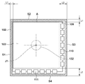
図2は、図1における放射線撮像部101をX方向(正面)から見た内部構造図である。図2において、筐体102の断面形状は斜線部で表され、放射線の入射面(X方向)から見て、4つの側面S1〜S4を有している。放射線検出パネル103において、放射線像を取得することが可能な撮影領域はAのような矩形領域で示される。なお、図2で説明する放射線検出パネル103は、その撮影領域Aが、縦横で長さが等しい正方形の撮影領域を有している。縦横で長さが異なる長方形の撮影領域を放射線検出パネル103が有している場合については、第3実施形態で説明する。
FIG. 2 is an internal structure diagram of the
ガラス基板109の右端側の側面と下端側の側面には、FPC110、111が接続されており、残りの2辺には、FPCは接続されていない。FPCが接続される2辺では、撮影領域Aの外側にFPCを接続する接続用電極を有する為、これらを有さない辺に対して、ガラス基板109端部から撮影領域Aまでの距離が長くなる。また、FPCが接続される2辺では、FPCを引き回すスペースを、ガラス基板109端部と筐体102内壁との間に必要とする。筐体102の側面S1、S2における額縁長さは、筐体102とガラス基板109との間に介在する部材がほぼ同じであることから、同一長さL1と仮定する。側面S3、S4における額縁長さも同様の考えよりL2と仮定すると、接続用電極部の有無、FPCの配置スペースの差により、L1<L2の関係が成り立つ。すなわち、撮影領域Aと平行な平面内において筐体102の少なくとも一つの側面から撮影領域Aまでの距離(L1)が筐体102の他の側面から撮影領域Aまでの距離(L2)よりも短くなる。
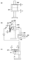
図3は、第1実施形態に係る放射線撮影装置の全体構成を示す図であり、放射線撮像部とX線管球を支持する支持構造の構成例を示している。放射線撮像部101は、C型の形状を成す支持アーム121の一端に支持されている。支持アーム121の反対側の端部には、X線管球122が放射線撮像部101と対向するように支持されている。また、支持アーム121はアームホルダ124により保持されている。アームホルダ124は、支持アーム121を円弧形状に沿った方向(C方向)に摺動させる機構を有している。
FIG. 3 is a diagram illustrating an overall configuration of the radiation imaging apparatus according to the first embodiment, and illustrates a configuration example of a support structure that supports the radiation imaging unit and the X-ray tube. The
更に、アームホルダ124は、基台部125により保持されている。基台部125は、アームホルダ124を回転軸J2を中心に、D方向に回転する回転機構を有している。また、基台部125は、支持アーム121を上下方向に昇降移動し、床からの高さを変えることができる昇降機構も内蔵している。
Further, the
支持アーム121は、C方向の摺動とD方向の回転及び昇降による上下移動を組み合わせることにより、放射線撮像部101とX線管球122とを対向状態を維持したまま、被検体Pに対して任意の方向から撮影を行うことが可能となっている。
The
また、放射線撮像部101と支持アーム121の接続箇所には、回転機構部131を有する。図1に示すように、回転機構部131は、支持アーム121に固定された固定部132に対して、放射線撮像部101に取り付けられた回転部133が回転可能に接続されている。回転機構部131の回転軸J1は、放射線撮像部101の撮影平面に対して交差する方向(垂直方向)にあり、図2に示すように、撮影領域Aの中心を通る位置にある。また、この回転軸J1は、X線管球122の光軸とも一致している。
In addition, a
回転機構部131の駆動は、モータ及びこのモータを駆動するドライバ等からなる回転駆動部134により行われ、回転制御部135により制御される。回転機構部131の近傍には、放射線撮像部101の傾斜状態を測定する傾斜検出部136を有し、傾斜検出部136の検出結果は回転制御部135に送られる。
The
図4は、図3の構成をY方向から見た図であり、図4を用いて放射線撮影装置の撮影時の各部の動作を説明する。図4において、被検体Pは天板137上に横たわっており、天板137は脚部138を介して床上に支持されている。なお、本実施形態では、基台部125に昇降機構を設けているが、昇降機構を基台部125の代わりに脚部138に設けた構成としても良い。
FIG. 4 is a diagram of the configuration of FIG. 3 viewed from the Y direction, and the operation of each unit during imaging of the radiation imaging apparatus will be described with reference to FIG. In FIG. 4, the subject P lies on a
放射線撮影装置の各構成要素は初期位置として任意の位置に設定可能であるが、説明の為、図4(a)の状態を初期位置とする。図4(a)では、X線管球122が下方に、放射線撮像部101が上方に位置し、放射線撮像部101の狭額縁である側面S2が右側に有る状態である。この状態から被検体Pの右斜め下方から放射線を照射し、透過画像を得る配置に変更する。支持アーム121を回転軸J2周りに左回転させることにより、X線管球122と放射線撮像部101を結ぶ回転軸J1を傾けていく。支持アーム121の回転軸J2周りの左回転に伴い、放射線撮像部101は、図4(b)のように、被検体Pに対する左端の位置が被検体Pに対する右端の位置より低く傾いた状態となる。この傾きは、傾斜情報として傾斜検出部136により検出され、検出された傾斜情報は、回転制御部135に送られる。回転制御部135は、傾斜情報より放射線撮像部101の狭額縁が左側に位置するように、回転駆動部134に駆動信号を送り、放射線撮像部101を回転軸J1回りに回転させる。本実施形態では、側面S1とS2における額縁長さを同じ長さとしたので、S1面が左側に位置するように放射線撮像部101を入射面側から見て90°左回転させれば良い。放射線撮像部101の傾斜及び回転移動により、放射線撮像部101の狭額縁の側面S1が被検体Pに近づいた位置(撮影条件に応じた方向に向けられた位置)に配置された状態になる(図4(b))。この状態から必要に応じて、基台部125により支持アーム121を鉛直方向に移動し、被検体Pに対して放射線撮像部101の位置を調整した後、撮影が行われる。
Each component of the radiation imaging apparatus can be set to an arbitrary position as an initial position. For the sake of explanation, the state shown in FIG. FIG. 4A shows a state in which the
また、支持アーム121をC方向に摺動させて撮影を行う場合や、C方向の摺動とD方向の回転移動を組み合わせて撮影を行う場合にも、傾斜検出部136は放射線撮像部101の姿勢を検出する。そして、回転制御部135は、傾斜検出部136の検出結果に応じて放射線撮像部101の狭額縁が被検体Pに近づいた位置(撮影条件に応じた方向に向けられた位置)に配置されるように制御する。
In addition, the
更に、放射線撮像部101の姿勢を傾斜検出部136を用いて求める代わりに、支持アーム121のC方向とD方向の回転移動量から算出し、この値を制御に用いる構成としても良い。
Further, instead of obtaining the posture of the
以上の述べたように、放射線撮像部101の姿勢に応じて、最も被検体Pに近い位置(撮影条件に応じた方向に向けられた位置)に狭額縁が配置されるように放射線撮像部101の回転が制御されるので、撮影領域Aを被検体Pに近接して配置することができる。
As described above, according to the posture of the
また、被検体から若干離して放射線撮像部101を配置する場合には、狭額縁は、被検体と放射線撮像部との間により広く隙間を確保することができ、被検体に対する圧迫感を和らげることができる。
In addition, when the
また、被検体Pが所定の距離以内に接近していることを検知する不図示の近接検出部が放射線撮像部101の筐体102に設けられており、近接検出部検出結果は回転制御部135に入力される。回転制御部135は、放射線撮像部101が被検体Pに対して所定の距離以内に接近した場合、回転を禁止するように制御する。この場合、回転制御部135は、放射線撮像部101が被検体Pに対して所定の距離以内に接近したことを作業者に知らせるための警告を出力する。
Further, a proximity detection unit (not shown) that detects that the subject P is approaching within a predetermined distance is provided in the
また、これらの動作は、放射線撮像部の姿勢に連動して変更されるので、作業者の負荷を軽減しつつ、放射線撮像部101の狭額縁を有効に利用した撮影を行うことができる。
Moreover, since these operations are changed in conjunction with the posture of the radiation imaging unit, it is possible to perform imaging using the narrow frame of the
(第2実施形態)
図5は、本発明の第2実施形態に係る放射線撮影装置の構成および動作を説明する図である。第1実施形態では、放射線撮像部101の姿勢に応じて狭額縁の配置を変更する構成を示したが、第2実施形態では被検体Pの撮影部位に関する撮影情報に基づいて、放射線撮像部201の狭額縁の配置を変更する構成を説明する。
(Second Embodiment)
FIG. 5 is a diagram for explaining the configuration and operation of a radiation imaging apparatus according to the second embodiment of the present invention. In the first embodiment, the configuration in which the arrangement of the narrow frame is changed according to the posture of the
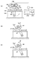
図5(a)は、放射線入射方向から見た図であり、放射線撮像部201は立位スタンド202に取り付けられている。図5(b)は、図5(a)の側面図である。放射線撮像部201は、側面から撮影領域までの距離がL3である狭額縁側が上側に配置され、L3よりも距離の長いL4の額縁長さを有する側面が下側に配置されている。立位スタンド202は、スライダ203と支柱204からなる。スライダ203は、支柱204に対して、上下方向に移動するスライド機能と、任意の高さで固定するロック機能を有している。放射線撮像部201とスライダ203との接続部には、回転軸J3を中心に放射線撮像部201を回転させる回転機構部205、及び、放射線撮像部201を水平状態に変位させるチルト機構部206を有している。
FIG. 5A is a diagram viewed from the radiation incident direction, and the
回転機構部205には、モータ及びこのモータを駆動するドライバ等の回転駆動部207が組み込まれ、回転駆動部207は、回転制御部208により制御され回転、停止を行う。回転制御部208は、コンソール209内の撮影制御部210に接続される。
The
コンソール209には、撮影装置全体の動作を司るCPUや、制御プログラムを含む各種プログラムが記憶させたROM等を備えた撮影制御部210、及び、操作メニューを表示し、表示した各種情報に対して操作指示を入力する操作パネル211を備える。
The
操作パネル211より入力される情報として、例えば、被検体の撮影部位の情報がある。頭部、胸部、腹部、下肢等の撮影部位の選択メニューを用意しておき、入力された撮影部位の情報に応じて、撮影制御部210は、照射する放射線の管電圧、管電流等の撮影条件を設定する。作業者は、撮影オーダに応じて、部位を選択することにより撮影条件が設定され、設定作業の簡略化が図られている。
As information input from the
同時に、撮影制御部210は、入力された撮影部位の情報により、放射線撮像部201の狭額縁の位置を決め、信号を回転制御部208に送る。回転制御部208は、狭額縁が所定の位置となるように、回転駆動部207を駆動させ、所定量回転させた後、固定する。
At the same time, the
例えば、胸部撮影では、撮影条件に応じた方向に向けられた位置として、被検体の撮影部位に近い上側に狭額縁を配置することにより、被検体の肺野上部(肺尖)まで撮影が行える。反対に、座った状態での撮影や下肢撮影では、被検体の撮影部位に近い下側に狭額縁を配置することにより、下側での撮影領域を広げることができる。 For example, in chest radiography, an image can be taken up to the upper lung field (pulmonary apex) of the subject by arranging a narrow frame on the upper side close to the imaging region of the subject as a position oriented in the direction according to the imaging conditions. . On the other hand, in imaging in a sitting state or in lower limbs, the imaging area on the lower side can be expanded by arranging a narrow frame on the lower side near the imaging site of the subject.
チルト機構部206を使用して放射線撮像部201を水平状態にして撮影を行う場合、図5(c)のように被検体に近接する側(筐体の側面から撮影領域までの距離がL3である狭額縁側が左側)が狭額縁となるように放射線撮像部201の配置を制御する。これにより、被検体が撮影姿勢を取ることを容易としている。
When imaging is performed with the
このように、撮影情報に応じて放射線撮像部201の狭額縁の配置が自動で変更されるので、作業者の負荷を軽減しつつ、放射線撮像部201の狭額縁を有効に利用した撮影を行うことができる。
As described above, since the arrangement of the narrow frame of the
(第3実施形態)
図6、図7は、本発明の第3実施形態に係る放射線撮影装置の説明図である。第3実施形態では、放射線撮像部の姿勢と共に、入力された撮影情報を利用して、放射線撮像部の狭額縁の配置を制御している。
(Third embodiment)
6 and 7 are explanatory views of a radiation imaging apparatus according to the third embodiment of the present invention. In 3rd Embodiment, the arrangement | positioning of the narrow frame of a radiation imaging part is controlled using the imaging | photography information input together with the attitude | position of a radiation imaging part.
第3実施形態の構成は、第1実施形態で示した構成とほぼ同じであるが、放射線撮像部の撮影領域が図6で示すような長方形(第1実施形態では正方形)である点と、第2実施形態と同様に回転制御部に撮影情報が入力されている点が異なる。すなわち、放射線撮像部の狭額縁の配置は、傾斜検出部136の傾斜情報と、操作パネル211を介して入力される被検体の撮影部位の情報を用いて制御される。
The configuration of the third embodiment is almost the same as the configuration shown in the first embodiment, but the imaging region of the radiation imaging unit is a rectangle (square in the first embodiment) as shown in FIG. Similar to the second embodiment, imaging information is input to the rotation control unit. That is, the arrangement of the narrow frame of the radiation imaging unit is controlled using the tilt information of the
図6は、図2と同様に放射線撮像部301を正面から見た内部構造図を示し、放射線検出パネル303の撮影領域Bは、縦横で長さが異なり、長辺を横方向に、短辺を縦方向に配置してある。FPCの接続場所については、図2と同様の位置とし、筐体302の4つの側面をS5〜S8とする。側面S5、S6における額縁長さをL5、側面S7、S8における額縁長さをL6とする。接続用電極部とFPCの配線スペースの有無により、横方向の額縁長さ及び縦方向の額縁長さにおいて、共にL5<L6の関係が成り立つ。すなわち、撮影領域Bと平行な平面内において筐体302の少なくとも一つの側面から撮影領域Bまでの距離(L5)が筐体302の他の側面から撮影領域Bまでの距離(L6)よりも短くなる。
6 shows an internal structure diagram of the
図7を用いて撮影時の各部の動作を説明する。放射線撮像部301の筐体302は直方体形状を成している。また、回転制御部333には、傾斜検出部136(姿勢検知部)からの信号と共に、撮影制御部210からの情報も入力される。また、撮影制御部210には操作パネル211が接続されている。操作パネル211を介して被検体の撮影部位の情報が入力される。
The operation of each unit during shooting will be described with reference to FIG. The
図7(a)を初期状態として、図4と同様に、右斜め下方から放射線を照射する配置に変更する動作を説明する。図7(a)では、放射線撮像部301の狭額縁である側面S6(L5)が右側に、撮影領域Bの短辺側が被検体Pの体軸J7に沿う方向に配置してある状態である。図7(a)の状態から、支持アーム121を回転軸J2の回りに左回転させることで、放射線撮像部301は左下がりに傾斜が生じ、傾斜検出部136で検出された傾斜情報は、回転制御部333に送られる。回転制御部333は、放射線撮像部301の狭額縁の面が下部に位置するように回転制御を行うが、この時、操作パネル211からの入力情報も参照する。撮影領域が長方形で有る為、操作パネル211より撮影に適した配置を選択可能としている。また、この選択は、撮影部位と対応するように設定しておくことにより、撮影部位の選択により配置が決まるようにしても良い。
With reference to FIG. 7A as an initial state, an operation for changing to an arrangement in which radiation is irradiated from the lower right side in the same manner as in FIG. 4 will be described. In FIG. 7A, the side surface S6 (L5), which is a narrow frame of the
撮影領域Bの長辺側が、被検体Pの体軸J7に沿って配置するように選択されている場合、回転制御部333は、側面S5が左側になるように、放射線撮像部301を回転させ、図7(b)の状態に変更する。また、撮影領域Bの短辺側を体軸J7に沿って配置するように選択されている場合、回転制御部333は、側面S6が左側になるように、放射線撮像部301を回転させ、図7(c)の状態に変更する。回転制御部333は、側面S5または側面S6を左側に配置するかを、撮影部位の選択に応じて判定し、判定結果に基づいて放射線撮像部301を回転させる。
When the long side of the imaging region B is selected so as to be arranged along the body axis J7 of the subject P, the
このように、放射線撮像部301の姿勢(傾斜情報)とともに、撮影情報を使用することにより、撮影領域Bが指定した向きに配置されると共に、放射線撮影部の狭額縁の辺が配置される。
In this way, by using the imaging information together with the posture (tilt information) of the
(第4実施形態)
図8は第4実施形態に係る放射線撮影装置の構成および動作を説明する図である。第4実施形態では、放射線撮像部の水平方向の位置情報に応じて、狭額縁の配置を制御している。
(Fourth embodiment)
FIG. 8 is a diagram illustrating the configuration and operation of the radiation imaging apparatus according to the fourth embodiment. In 4th Embodiment, arrangement | positioning of a narrow frame is controlled according to the positional information on the horizontal direction of a radiation imaging part.
図8(a)は、被検体を載せる天板402を上方より見た図であり、放射線撮像部401は撮影台(保持部材800)に保持された状態を示している。図8(b)は、図8(a)を側方から見た図である。放射線撮像部401は、天板402の下でキャリッジ403に載り、キャリッジ403は、不図示の駆動機構によってレール404上を水平方向に移動することにより、水平方向の任意の位置に移動することが可能である。放射線撮像部401とキャリッジ403との間には、放射線撮像部を回転させる回転機構部405を有する。回転機構部405の回転は、回転制御部406からの信号により行われる。
FIG. 8A is a view of the
図8(c)は、放射線撮像部401の移動に伴い、天板402の面内に対する狭額縁の配置が相対的に変更される動作を説明する図である。放射線撮像部401のX方向の移動において、全移動距離L6の両側から距離L8の範囲に放射線撮像部401が位置する場合、放射線撮像部の狭額縁が外側に向くように、回転制御部406は回転機構部405の制御を行う。同様に、Y方向の移動においては、全移動距離L7の両側から距離L9の範囲に放射線撮像部401が位置する場合、放射線撮像部401の狭額縁が外側に向くように、制御が行われる。なお、これらの領域に放射線撮像部が有るか否かは、位置検出器407で検出され、検出された位置情報は回転制御部406に入力される。回転制御部406は入力された位置情報を用いて回転機構部405の駆動を制御する。
FIG. 8C is a diagram illustrating an operation in which the arrangement of the narrow frame relative to the surface of the
放射線撮像部401を移動して撮像を行う場合、天板402の面内で、放射線撮像部401の狭額縁が外側に向くように放射線撮像部401を回転させることにより、同じ撮影領域を有する放射線撮像部でカバーできる撮影領域を可能な限り広げることができる。
When imaging is performed by moving the
上記の各実施形態によれば、放射線撮像部の狭額縁を撮影条件に応じた方向に向けた撮影を容易に行うことができ、撮影条件に応じた画像を取得可能な撮影技術の提供が可能になる。 According to each of the above embodiments, it is possible to easily perform imaging with the narrow frame of the radiation imaging unit directed in the direction according to the imaging condition, and it is possible to provide an imaging technique capable of acquiring an image according to the imaging condition. become.
以上の説明は本発明の好ましい実施形態について行ったが、本発明は、この実施形態に限定されず、種々の変形及び変更が可能である。また、放射線撮像部の撮影領域から筐体の側面までの距離の違いの要因として、放射線パネルの構造によるもので説明してきたが、他の構造的な要因で側面からの距離が異なる場合にも、同様な効果を得ることができる。 Although the above description has been given with respect to a preferred embodiment of the present invention, the present invention is not limited to this embodiment, and various modifications and changes can be made. In addition, as a factor of the difference in distance from the imaging area of the radiation imaging unit to the side of the housing, it has been explained by the structure of the radiation panel, but also when the distance from the side differs due to other structural factors A similar effect can be obtained.
(その他の実施形態)
また、本発明は、以下の処理を実行することによっても実現される。即ち、上述した実施形態の機能を実現するソフトウェア(プログラム)を、ネットワーク又は各種記憶媒体を介してシステム或いは装置に供給し、そのシステム或いは装置のコンピュータ(またはCPUやMPU等)がプログラムを読み出して実行する処理である。
(Other embodiments)
The present invention can also be realized by executing the following processing. That is, software (program) that realizes the functions of the above-described embodiments is supplied to a system or apparatus via a network or various storage media, and a computer (or CPU, MPU, etc.) of the system or apparatus reads the program. It is a process to be executed.
Claims (6)
前記撮影領域に対して交差する方向の回転軸を中心として前記放射線撮像手段を回転する回転手段と、
前記撮影領域との距離が短い前記筐体の一つの側面を、撮影条件に応じた方向に向けるように、前記回転手段の回転を制御する制御手段と、
を有することを特徴とする放射線撮影装置。 A detection unit having a rectangular imaging region and a position in the casing where a distance from one side surface of the casing to the imaging region is shorter than a distance from the other side surface to the imaging region Radiation imaging means in which the detector is disposed;
Rotating means for rotating the radiation imaging means around a rotation axis in a direction intersecting the imaging region;
Control means for controlling the rotation of the rotating means so that one side surface of the housing having a short distance to the imaging region is directed in a direction according to imaging conditions;
A radiation imaging apparatus comprising:
前記支持手段に支持された前記放射線撮像手段を、被検体に対して傾ける傾斜手段と、
前記撮影条件として、前記被検体に対する前記放射線撮像手段の傾斜情報を検出する傾斜検出手段と、を更に有し、
前記制御手段は、前記傾斜情報を用いて前記回転手段の回転を制御することを特徴とする請求項1に記載の放射線撮影装置。 Support means for supporting the radiation imaging means;
Inclining means for inclining the radiation imaging means supported by the supporting means with respect to the subject;
An inclination detecting means for detecting inclination information of the radiation imaging means with respect to the subject as the imaging condition;
The radiographic apparatus according to claim 1, wherein the control unit controls rotation of the rotation unit using the tilt information.
前記制御手段は、前記撮影部位の情報を用いて前記回転手段の回転を制御することを特徴とする請求項1または2に記載の放射線撮影装置。 As the imaging condition, further comprising an input means for inputting information on the imaging region of the subject,
The radiation imaging apparatus according to claim 1, wherein the control unit controls rotation of the rotation unit using information on the imaging region.
前記撮影条件として、前記被検体の撮影部位の情報を入力する入力手段と、を更に有し、
前記傾斜情報と前記被検体の撮影部位の情報とを用いて、前記制御手段は前記回転手段の回転を制御することを特徴とする請求項1に記載の放射線撮影装置。 Inclination detection means for detecting inclination information of the radiation imaging means with respect to the subject as the imaging condition;
An input means for inputting information on the imaging region of the subject as the imaging condition;
The radiation imaging apparatus according to claim 1, wherein the control unit controls the rotation of the rotation unit using the tilt information and information on the imaging region of the subject.
前記面内において前記放射線撮像手段を水平方向に移動する移動手段と、
前記撮影条件として、前記面内における前記放射線撮像手段の位置情報を検出する位置検出手段と、を更に有し、
前記制御手段は、前記位置情報を用いて前記回転手段の回転を制御することを特徴とする請求項1に記載の放射線撮影装置。 Holding means for holding the radiation imaging means in a plane parallel to the imaging region;
Moving means for moving the radiation imaging means in a horizontal direction within the plane;
As the imaging condition, further comprising position detection means for detecting position information of the radiation imaging means in the plane,
The radiographic apparatus according to claim 1, wherein the control unit controls rotation of the rotating unit using the position information.
前記撮影領域に対して交差する方向の回転軸を中心として前記放射線撮像手段を回転する回転手段と、
を有する放射線撮影装置の制御方法であって、
前記放射線撮影装置の制御手段が、前記撮影領域との距離が短い前記筐体の一つの側面を、撮影条件に応じた方向に向けるように、前記回転手段の回転を制御する制御工程
を有することを特徴とする放射線撮影装置の制御方法。 A detection unit having a rectangular imaging region and a position in the casing where a distance from one side surface of the casing to the imaging region is shorter than a distance from the other side surface to the imaging region Radiation imaging means in which the detector is disposed;
Rotating means for rotating the radiation imaging means around a rotation axis in a direction intersecting the imaging region;
A method for controlling a radiation imaging apparatus comprising:
The control unit of the radiation imaging apparatus has a control step of controlling the rotation of the rotating unit so that one side surface of the housing having a short distance from the imaging region is directed in a direction according to imaging conditions. A control method for a radiographic apparatus characterized by the above.
Priority Applications (2)
| Application Number | Priority Date | Filing Date | Title |
|---|---|---|---|
| JP2013029436A JP2014155674A (en) | 2013-02-18 | 2013-02-18 | Radiographic device and control method for radiographic device |
| US14/164,881 US20140231662A1 (en) | 2013-02-18 | 2014-01-27 | Radiation imaging apparatus and method of controlling radiation imaging apparatus |
Applications Claiming Priority (1)
| Application Number | Priority Date | Filing Date | Title |
|---|---|---|---|
| JP2013029436A JP2014155674A (en) | 2013-02-18 | 2013-02-18 | Radiographic device and control method for radiographic device |
Publications (2)
| Publication Number | Publication Date |
|---|---|
| JP2014155674A true JP2014155674A (en) | 2014-08-28 |
| JP2014155674A5 JP2014155674A5 (en) | 2016-03-31 |
Family
ID=51350520
Family Applications (1)
| Application Number | Title | Priority Date | Filing Date |
|---|---|---|---|
| JP2013029436A Pending JP2014155674A (en) | 2013-02-18 | 2013-02-18 | Radiographic device and control method for radiographic device |
Country Status (2)
| Country | Link |
|---|---|
| US (1) | US20140231662A1 (en) |
| JP (1) | JP2014155674A (en) |
Families Citing this family (1)
| Publication number | Priority date | Publication date | Assignee | Title |
|---|---|---|---|---|
| JP6609105B2 (en) | 2015-03-24 | 2019-11-20 | キヤノン株式会社 | Radiation imaging apparatus and radiation imaging system |
Citations (4)
| Publication number | Priority date | Publication date | Assignee | Title |
|---|---|---|---|---|
| JP2000201909A (en) * | 1999-01-11 | 2000-07-25 | Toshiba Corp | X-ray diagnostic device |
| JP2002143138A (en) * | 2000-11-07 | 2002-05-21 | Canon Inc | Cassette type x-ray picture image radiographic equipment |
| JP2005323733A (en) * | 2004-05-13 | 2005-11-24 | Fuji Photo Film Co Ltd | Mammographic x-ray equipment |
| JP2010057596A (en) * | 2008-09-02 | 2010-03-18 | Canon Inc | Radiation imaging apparatus and imaging method of the same |
Family Cites Families (3)
| Publication number | Priority date | Publication date | Assignee | Title |
|---|---|---|---|---|
| WO2006085232A1 (en) * | 2005-02-10 | 2006-08-17 | Koninklijke Philips Electronics N.V. | Portable x-ray detector plate with shock absorption |
| JP5576620B2 (en) * | 2009-04-16 | 2014-08-20 | キヤノン株式会社 | Control device and control method thereof |
| US9055913B2 (en) * | 2011-04-29 | 2015-06-16 | General Electric Company | System and method for orienting an X-ray detector |
-
2013
- 2013-02-18 JP JP2013029436A patent/JP2014155674A/en active Pending
-
2014
- 2014-01-27 US US14/164,881 patent/US20140231662A1/en not_active Abandoned
Patent Citations (4)
| Publication number | Priority date | Publication date | Assignee | Title |
|---|---|---|---|---|
| JP2000201909A (en) * | 1999-01-11 | 2000-07-25 | Toshiba Corp | X-ray diagnostic device |
| JP2002143138A (en) * | 2000-11-07 | 2002-05-21 | Canon Inc | Cassette type x-ray picture image radiographic equipment |
| JP2005323733A (en) * | 2004-05-13 | 2005-11-24 | Fuji Photo Film Co Ltd | Mammographic x-ray equipment |
| JP2010057596A (en) * | 2008-09-02 | 2010-03-18 | Canon Inc | Radiation imaging apparatus and imaging method of the same |
Also Published As
| Publication number | Publication date |
|---|---|
| US20140231662A1 (en) | 2014-08-21 |
Similar Documents
| Publication | Publication Date | Title |
|---|---|---|
| KR101390190B1 (en) | X-ray photographing apparatus and method for using the same and x-ray image obtaining method | |
| WO2012144230A1 (en) | X-ray image diagnostic apparatus | |
| JP6400307B2 (en) | X-ray diagnostic imaging equipment | |
| JPWO2015011987A1 (en) | X-ray equipment | |
| JP2019213583A (en) | Proximity operation x-ray fluoroscopic imaging apparatus | |
| KR100923097B1 (en) | X-ray photographing device | |
| JP2014155674A (en) | Radiographic device and control method for radiographic device | |
| JP5317757B2 (en) | Radiography equipment | |
| JP2010264054A (en) | X-ray imaging apparatus | |
| JP6083240B2 (en) | Mobile X-ray equipment | |
| JP2022174736A (en) | Panoramic x-ray imaging apparatus | |
| JP2018186842A (en) | Control device, radiographic imaging apparatus, radiographic imaging method, and radiographic imaging program | |
| JP6687036B2 (en) | X-ray equipment | |
| JP2015051236A (en) | X-ray imaging apparatus | |
| JP4577214B2 (en) | X-ray inspection equipment | |
| JP6541883B1 (en) | Dental X-ray equipment | |
| JP3908711B2 (en) | X-ray equipment | |
| JP2011072582A (en) | X-ray imaging apparatus | |
| JP5676883B2 (en) | X-ray CT system | |
| JP5966647B2 (en) | X-ray equipment | |
| JP2005021470A (en) | X-ray tube supporting device | |
| JP2005021328A (en) | X-ray tomography system | |
| JP7458613B2 (en) | Panoramic X-ray imaging device | |
| JP6947429B2 (en) | Dental X-ray equipment and line-of-sight derivatives | |
| JP2001120526A (en) | Fluoroscopic photographing apparatus |
Legal Events
| Date | Code | Title | Description |
|---|---|---|---|
| A521 | Request for written amendment filed |
Free format text: JAPANESE INTERMEDIATE CODE: A523 Effective date: 20160215 |
|
| A621 | Written request for application examination |
Free format text: JAPANESE INTERMEDIATE CODE: A621 Effective date: 20160215 |
|
| A977 | Report on retrieval |
Free format text: JAPANESE INTERMEDIATE CODE: A971007 Effective date: 20161221 |
|
| A131 | Notification of reasons for refusal |
Free format text: JAPANESE INTERMEDIATE CODE: A131 Effective date: 20170105 |
|
| A02 | Decision of refusal |
Free format text: JAPANESE INTERMEDIATE CODE: A02 Effective date: 20170718 |