JP6400307B2 - X-ray diagnostic imaging equipment - Google Patents
X-ray diagnostic imaging equipment Download PDFInfo
- Publication number
- JP6400307B2 JP6400307B2 JP2014046830A JP2014046830A JP6400307B2 JP 6400307 B2 JP6400307 B2 JP 6400307B2 JP 2014046830 A JP2014046830 A JP 2014046830A JP 2014046830 A JP2014046830 A JP 2014046830A JP 6400307 B2 JP6400307 B2 JP 6400307B2
- Authority
- JP
- Japan
- Prior art keywords
- information
- top plate
- position information
- ray
- unit
- Prior art date
- Legal status (The legal status is an assumption and is not a legal conclusion. Google has not performed a legal analysis and makes no representation as to the accuracy of the status listed.)
- Active
Links
- 238000002059 diagnostic imaging Methods 0.000 title claims description 39
- 238000001514 detection method Methods 0.000 claims description 119
- 238000006073 displacement reaction Methods 0.000 claims description 33
- 238000012937 correction Methods 0.000 claims description 26
- 238000003384 imaging method Methods 0.000 claims description 21
- 238000004364 calculation method Methods 0.000 claims description 19
- 230000001678 irradiating effect Effects 0.000 claims description 9
- 238000012545 processing Methods 0.000 description 18
- 238000010586 diagram Methods 0.000 description 10
- 238000003780 insertion Methods 0.000 description 9
- 230000037431 insertion Effects 0.000 description 9
- 238000000034 method Methods 0.000 description 9
- 238000006243 chemical reaction Methods 0.000 description 7
- 238000013500 data storage Methods 0.000 description 7
- 239000000725 suspension Substances 0.000 description 7
- 238000004891 communication Methods 0.000 description 6
- 230000006870 function Effects 0.000 description 6
- 238000012360 testing method Methods 0.000 description 4
- 238000012423 maintenance Methods 0.000 description 3
- UNPLRYRWJLTVAE-UHFFFAOYSA-N Cloperastine hydrochloride Chemical compound Cl.C1=CC(Cl)=CC=C1C(C=1C=CC=CC=1)OCCN1CCCCC1 UNPLRYRWJLTVAE-UHFFFAOYSA-N 0.000 description 2
- 238000003745 diagnosis Methods 0.000 description 2
- 238000002583 angiography Methods 0.000 description 1
- 239000002131 composite material Substances 0.000 description 1
- 230000008602 contraction Effects 0.000 description 1
- 210000003746 feather Anatomy 0.000 description 1
- 239000000696 magnetic material Substances 0.000 description 1
- 239000002184 metal Substances 0.000 description 1
- 238000012986 modification Methods 0.000 description 1
- 230000004048 modification Effects 0.000 description 1
- 230000003287 optical effect Effects 0.000 description 1
- 230000008054 signal transmission Effects 0.000 description 1
- 229920002379 silicone rubber Polymers 0.000 description 1
- 238000004846 x-ray emission Methods 0.000 description 1
Images


Classifications
-
- A—HUMAN NECESSITIES
- A61—MEDICAL OR VETERINARY SCIENCE; HYGIENE
- A61B—DIAGNOSIS; SURGERY; IDENTIFICATION
- A61B6/00—Apparatus or devices for radiation diagnosis; Apparatus or devices for radiation diagnosis combined with radiation therapy equipment
- A61B6/54—Control of apparatus or devices for radiation diagnosis
- A61B6/547—Control of apparatus or devices for radiation diagnosis involving tracking of position of the device or parts of the device
-
- A—HUMAN NECESSITIES
- A61—MEDICAL OR VETERINARY SCIENCE; HYGIENE
- A61B—DIAGNOSIS; SURGERY; IDENTIFICATION
- A61B6/00—Apparatus or devices for radiation diagnosis; Apparatus or devices for radiation diagnosis combined with radiation therapy equipment
- A61B6/04—Positioning of patients; Tiltable beds or the like
- A61B6/0487—Motor-assisted positioning
-
- A—HUMAN NECESSITIES
- A61—MEDICAL OR VETERINARY SCIENCE; HYGIENE
- A61B—DIAGNOSIS; SURGERY; IDENTIFICATION
- A61B6/00—Apparatus or devices for radiation diagnosis; Apparatus or devices for radiation diagnosis combined with radiation therapy equipment
- A61B6/42—Arrangements for detecting radiation specially adapted for radiation diagnosis
- A61B6/4208—Arrangements for detecting radiation specially adapted for radiation diagnosis characterised by using a particular type of detector
- A61B6/4233—Arrangements for detecting radiation specially adapted for radiation diagnosis characterised by using a particular type of detector using matrix detectors
-
- A—HUMAN NECESSITIES
- A61—MEDICAL OR VETERINARY SCIENCE; HYGIENE
- A61B—DIAGNOSIS; SURGERY; IDENTIFICATION
- A61B6/00—Apparatus or devices for radiation diagnosis; Apparatus or devices for radiation diagnosis combined with radiation therapy equipment
- A61B6/44—Constructional features of apparatus for radiation diagnosis
- A61B6/4429—Constructional features of apparatus for radiation diagnosis related to the mounting of source units and detector units
- A61B6/4435—Constructional features of apparatus for radiation diagnosis related to the mounting of source units and detector units the source unit and the detector unit being coupled by a rigid structure
- A61B6/4441—Constructional features of apparatus for radiation diagnosis related to the mounting of source units and detector units the source unit and the detector unit being coupled by a rigid structure the rigid structure being a C-arm or U-arm
-
- A—HUMAN NECESSITIES
- A61—MEDICAL OR VETERINARY SCIENCE; HYGIENE
- A61B—DIAGNOSIS; SURGERY; IDENTIFICATION
- A61B6/00—Apparatus or devices for radiation diagnosis; Apparatus or devices for radiation diagnosis combined with radiation therapy equipment
- A61B6/44—Constructional features of apparatus for radiation diagnosis
- A61B6/4429—Constructional features of apparatus for radiation diagnosis related to the mounting of source units and detector units
- A61B6/4464—Constructional features of apparatus for radiation diagnosis related to the mounting of source units and detector units the source unit or the detector unit being mounted to ceiling
-
- A—HUMAN NECESSITIES
- A61—MEDICAL OR VETERINARY SCIENCE; HYGIENE
- A61B—DIAGNOSIS; SURGERY; IDENTIFICATION
- A61B6/00—Apparatus or devices for radiation diagnosis; Apparatus or devices for radiation diagnosis combined with radiation therapy equipment
- A61B6/44—Constructional features of apparatus for radiation diagnosis
- A61B6/4476—Constructional features of apparatus for radiation diagnosis related to motor-assisted motion of the source unit
-
- A—HUMAN NECESSITIES
- A61—MEDICAL OR VETERINARY SCIENCE; HYGIENE
- A61B—DIAGNOSIS; SURGERY; IDENTIFICATION
- A61B6/00—Apparatus or devices for radiation diagnosis; Apparatus or devices for radiation diagnosis combined with radiation therapy equipment
- A61B6/48—Diagnostic techniques
- A61B6/486—Diagnostic techniques involving generating temporal series of image data
- A61B6/487—Diagnostic techniques involving generating temporal series of image data involving fluoroscopy
-
- A—HUMAN NECESSITIES
- A61—MEDICAL OR VETERINARY SCIENCE; HYGIENE
- A61B—DIAGNOSIS; SURGERY; IDENTIFICATION
- A61B6/00—Apparatus or devices for radiation diagnosis; Apparatus or devices for radiation diagnosis combined with radiation therapy equipment
- A61B6/54—Control of apparatus or devices for radiation diagnosis
- A61B6/545—Control of apparatus or devices for radiation diagnosis involving automatic set-up of acquisition parameters
Landscapes
- Health & Medical Sciences (AREA)
- Life Sciences & Earth Sciences (AREA)
- Medical Informatics (AREA)
- Engineering & Computer Science (AREA)
- Physics & Mathematics (AREA)
- Radiology & Medical Imaging (AREA)
- Heart & Thoracic Surgery (AREA)
- Nuclear Medicine, Radiotherapy & Molecular Imaging (AREA)
- Optics & Photonics (AREA)
- Pathology (AREA)
- Biophysics (AREA)
- Biomedical Technology (AREA)
- High Energy & Nuclear Physics (AREA)
- Molecular Biology (AREA)
- Surgery (AREA)
- Animal Behavior & Ethology (AREA)
- General Health & Medical Sciences (AREA)
- Public Health (AREA)
- Veterinary Medicine (AREA)
- Mathematical Physics (AREA)
- Apparatus For Radiation Diagnosis (AREA)
Description
本発明は、X線画像診断装置に関する。 The present invention relates to an X-ray image diagnostic apparatus.
患者(被検体)を撮影する患者撮影像において、撮影方向を示す座標系として臨床角を用いた座標系(これを臨床角座標ともいう。)が一般的に利用されている。 In a patient photographed image for photographing a patient (subject), a coordinate system using clinical angles (also referred to as clinical angle coordinates) is generally used as a coordinate system indicating a photographing direction.
この臨床角座標系が示す座標位置は、X線管球とX線検出器とを有する保持装置の駆動軸(可動軸)の位置決め結果として、保持装置側で決定される。 The coordinate position indicated by the clinical angular coordinate system is determined on the holding device side as a positioning result of the drive shaft (movable shaft) of the holding device having the X-ray tube and the X-ray detector.
すなわち、一般的なX線画像診断装置では、寝台位置(天板位置)を固定した状態を想定しており、保持装置側で制御する駆動軸(可動軸)の駆動制御に基づいて、X線管球とX線検出器との位置決め結果により臨床角座標系の座標位置を決定している。 That is, in a general X-ray diagnostic imaging apparatus, it is assumed that the bed position (top position) is fixed, and based on the drive control of the drive shaft (movable shaft) controlled on the holding device side, The coordinate position of the clinical angular coordinate system is determined by the positioning result of the tube and the X-ray detector.
このように、一般的なX線画像診断装置は、保持装置側の駆動制御のみに基づいて装置の位置決めを行い、固定された状態の寝台位置(天板位置)との位置関係により、患者(被検体)を撮影する際の角度として臨床角座標を算出している。 As described above, the general X-ray diagnostic imaging apparatus positions the apparatus based only on the drive control on the holding device side, and determines the patient (by the positional relationship with the bed position (top position) in a fixed state) The clinical angle coordinates are calculated as the angle when the subject is imaged.
臨床角座標は、上述したように、X線管球とX線検出器とを有する保持装置の駆動軸(可動軸)の駆動制御のみから算出されていた。そのため、従来では、撮影対象となる患者を含めた寝台位置または天板位置を、全く考慮していなかった。 As described above, the clinical angular coordinates are calculated only from the drive control of the drive shaft (movable shaft) of the holding device having the X-ray tube and the X-ray detector. For this reason, conventionally, no consideration has been given to the bed position or the top board position including the patient to be imaged.
したがって、保持装置が算出する臨床角座標には、寝台に設けられた天板の回転角度や天板の起倒角度などは一切反映されておらず、例えば、寝台の回転軸(駆動軸)が駆動し天板位置が変化することにより、天板の回転角度や天板の起倒角度が変化した場合には、保持装置側で算出する臨床角座標は、不正確な座標位置となってしまうことがある。 Therefore, the clinical angle coordinates calculated by the holding device do not reflect the rotation angle of the couch provided on the couch or the tilting angle of the couch, for example, the rotation axis (drive axis) of the couch If the rotation angle of the top plate or the tilting angle of the top plate changes as a result of driving and changing the top plate position, the clinical angle coordinates calculated on the holding device side will be inaccurate coordinate positions. Sometimes.
そこで、常に正確な位置と角度を示す臨床角座標を算出することができるX線画像診断装置が望まれていた。 Therefore, there has been a demand for an X-ray diagnostic imaging apparatus that can calculate clinical angular coordinates that always indicate an accurate position and angle.
本実施形態に係るX線画像診断装置は、上述した課題を解決するために、X線を照射するX線照射部と、前記X線を検出する検出部と、被検体を載置する移動可能な天板と、前記天板の位置情報を取得する天板位置情報取得部と、前記X線照射部の位置情報、前記X線照射部の角度情報、前記検出部の位置情報または前記検出部の角度情報の少なくともいずれかを取得して、前記被検体に前記X線を照射する際の関心位置を算出する関心位置算出部と、前記X線照射部の位置情報、前記X線照射部の角度情報、前記検出部の位置情報または前記検出部の角度情報の少なくともいずれかと、前記天板の位置情報との相対的な位置関係に基づいて、算出した前記関心位置を前記被検体の中心座標系の中心位置に置き換える中心座標置換部と、前記天板の位置情報の変位を、置き換えた前記中心位置からの相対的な移動量として、前記X線照射部の位置情報、前記X線照射部の角度情報、前記検出部の位置情報または前記検出部の角度情報の少なくともいずれかを補正する情報補正部と、補正した前記X線照射部の位置情報、前記X線照射部の角度情報、前記検出部の位置情報または前記検出部の角度情報に基づいて、前記X線照射部及び前記検出部を駆動する駆動制御部と、を備える。前記天板の位置情報の変位は、前記天板の鉛直軸中心の回転動作に伴う移動量を少なくとも含む。前記駆動制御部は、前記天板の位置情報の変位に応じて、前記関心位置に対する前記X線照射部の相対的な位置と、前記関心位置に対する前記検出部の相対的な位置との位置関係を保持するように前記X線照射部と前記検出部とを駆動する。 In order to solve the above-described problem, the X-ray diagnostic imaging apparatus according to the present embodiment can move an X-ray irradiation unit that irradiates X-rays, a detection unit that detects the X-rays, and a subject. A top plate, a top plate position information acquisition unit that acquires position information of the top plate , position information of the X-ray irradiation unit, angle information of the X-ray irradiation unit, position information of the detection unit, or the detection unit At least one of the angle information, and calculating a position of interest when the subject is irradiated with the X-ray; position information of the X-ray irradiation unit; Based on the relative positional relationship between the angle information, the position information of the detection unit or the angle information of the detection unit, and the position information of the top plate, the calculated position of interest is the center coordinates of the subject. a center coordinate replacement unit replacing the central position of the system, the The displacement of the position information of the plate, as the amount of relative movement from the center position is replaced, the position information of the X-ray irradiation unit, the angle information of the X-ray irradiation unit, position information or the detector of the detection unit Information correction unit that corrects at least one of the angle information, and the corrected position information of the X-ray irradiation unit, angle information of the X-ray irradiation unit, position information of the detection unit, or angle information of the detection unit A drive control unit that drives the X-ray irradiation unit and the detection unit . The displacement of the position information of the top plate includes at least a movement amount associated with the rotation operation of the top plate about the vertical axis. The drive control unit, in accordance with the displacement of the position information of the top plate, front Stories and relative position of the X-ray irradiation unit for Seki heart position, the relative position of the detector relative to the point of interest The X-ray irradiation unit and the detection unit are driven so as to maintain the positional relationship.
本実施形態に係るX線画像診断装置は、X線を照射するX線照射部と、前記X線を検出する検出部と、被検体を載置する移動可能な天板と、前記天板の位置情報を取得する天板位置情報取得部と、前記X線照射部の位置情報、前記X線照射部の角度情報、前記検出部の位置情報または前記検出部の角度情報の少なくともいずれかを取得して、前記被検体に前記X線を照射する際の関心位置を算出する関心位置算出部と、前記X線照射部の位置情報、前記X線照射部の角度情報、前記検出部の位置情報または前記検出部の角度情報の少なくともいずれかと、前記天板の位置情報との相対的な位置関係に基づいて、算出した前記関心位置を前記被検体の中心座標系の中心位置に置き換える中心座標置換部と、前記天板の位置情報の変位を、置き換えた前記中心位置からの相対的な移動量として、前記X線照射部の位置情報、前記X線照射部の角度情報、前記検出部の位置情報または前記検出部の角度情報の少なくともいずれかを補正する情報補正部と、補正した前記X線照射部の位置情報、前記X線照射部の角度情報、前記検出部の位置情報または前記検出部の角度情報に基づいて、前記X線照射部及び前記検出部を駆動する駆動制御部と、を備える。前記天板の位置情報の変位は、前記天板の鉛直軸中心の回転動作に伴う移動量を少なくとも含む。前記駆動制御部は、前記天板の位置情報の変位に応じて、前記関心位置に対する前記X線照射部の相対的な位置と、前記関心位置に対する前記検出部の相対的な位置との位置関係を保持するように前記X線照射部と前記検出部とを駆動する。 An X-ray diagnostic imaging apparatus according to this embodiment includes an X-ray irradiation unit that irradiates X-rays, a detection unit that detects the X-rays, a movable top plate on which a subject is placed, and the top plate Obtain at least one of a top board position information acquisition unit that acquires position information, position information of the X-ray irradiation unit, angle information of the X-ray irradiation unit, position information of the detection unit, or angle information of the detection unit And a position of interest calculation unit that calculates a position of interest when the subject is irradiated with the X-ray, position information of the X-ray irradiation unit, angle information of the X-ray irradiation unit, and position information of the detection unit. Alternatively, based on the relative positional relationship between at least one of the angle information of the detection unit and the position information of the top plate, the center coordinate replacement replaces the calculated position of interest with the center position of the center coordinate system of the subject. and parts, the displacement of the position information of the top plate, placed conversion As the relative movement amount from the center position, at least one of the position information of the X-ray irradiation unit, the angle information of the X-ray irradiation unit, the position information of the detection unit, or the angle information of the detection unit is corrected. And the corrected position information of the X-ray irradiation unit, the angle information of the X-ray irradiation unit, the position information of the detection unit, or the angle information of the detection unit, and the X-ray irradiation unit and the angle information of the detection unit A drive control unit that drives the detection unit . The displacement of the position information of the top plate includes at least a movement amount associated with the rotation operation of the top plate about the vertical axis. The drive control unit, in accordance with the displacement of the position information of the top plate, front Stories and relative position of the X-ray irradiation unit for Seki heart position, the relative position of the detector relative to the point of interest The X-ray irradiation unit and the detection unit are driven so as to maintain the positional relationship.
これにより、本実施形態に係るX線画像診断装置によれば、臨床角座標を利用する際に、天板の位置情報も考慮した、被検体を中心とした単一座標系の位置情報による撮影を行うことができる。 Thereby, according to the X-ray image diagnostic apparatus according to the present embodiment, when clinical angular coordinates are used, imaging is performed based on position information of a single coordinate system centered on the subject in consideration of position information of the top plate. It can be performed.
また、本実施形態に係るX線画像診断装置によれば、天板の位置情報も考慮して被検体を撮影することができるので、常に正確な位置と角度を示す臨床角座標を算出することができ、より精度の高い撮影画像データを得ることができる。 In addition, according to the X-ray image diagnostic apparatus according to the present embodiment, the subject can be imaged in consideration of the position information of the top board, so that clinical angular coordinates that always indicate an accurate position and angle can be calculated. And more accurate captured image data can be obtained.
本実施形態に係る実施形態を説明する前に、上述した従来の課題を明確にするため、課題について図面を用いて説明する。 Before describing the embodiment according to the present embodiment, the problem will be described with reference to the drawings in order to clarify the conventional problem described above.
図9は、従来のX線画像診断装置において、移動可能な天板29aに載置された被検体Pに対し、X線を照射する概略を示した説明図である。
FIG. 9 is an explanatory view showing an outline of irradiating a subject P placed on a
図9に示すように、従来のX線画像診断装置では、X線照射装置27と、検出装置28とによってX線撮影を行うようになっている。また、関心位置Kは、X線照射装置27及び検出装置28の位置情報と、X線の照射情報とに基づいて、被検体PにX線を照射する際の関心位置を示している。
As shown in FIG. 9, in the conventional X-ray image diagnostic apparatus, X-ray imaging is performed by an
従来のX線画像診断装置では、X線照射装置27と検出装置28とを保持する保持装置の駆動軸(可動軸)の動作のみから臨床角座標を算出し、関心位置Kを求めるようになっていた。
In a conventional X-ray diagnostic imaging apparatus, a clinical angular coordinate is calculated only from the operation of the drive shaft (movable shaft) of a holding device that holds the
そのため、従来のX線画像診断装置では、天板29aの位置や寝台(図示せず)の移動が考慮されておらず、天板29aや寝台の位置によっては正しい撮影像を得ることができなかった。
Therefore, in the conventional X-ray diagnostic imaging apparatus, the position of the
例えば、図9に示すように、被検体Pの関心位置Kは、被検体Pが天板29aに固定された状態であっても、天板29aの位置が上方向Uまたは下方向Dにずれた場合は、関心位置Kがずれてしまうので、医師や検査技師が得たい正確な撮影像を得ることができなかった。
For example, as shown in FIG. 9, the position of interest K of the subject P is shifted in the upward direction U or the downward direction D even when the subject P is fixed to the
なお、天板29aは、天板29aの下部に寝台が設けられており、その寝台は、天板29aを上下に移動させたり、体軸方向に天板29aを移動させたり、またはX−Z平面において回転させる駆動軸(可動軸)等を備えているものとする。
The
図10は、従来のX線画像診断装置において、天板29aに載置された被検体Pに対し、X線を照射する状態を、横から見た概略の説明図である。
FIG. 10 is a schematic explanatory view of a state in which X-rays are irradiated to the subject P placed on the
図10も同様に、X線照射装置27と、検出装置28とによってX線撮影を行うようになっている。従来のX線画像診断装置では、図9と同様に、X線照射装置27と検出装置28とを保持する保持装置の駆動軸(可動軸)の動作のみから臨床角座標を算出していたため、天板29aの位置や寝台の移動が考慮されておらず、天板29aや寝台の位置によっては正しい撮影像を得ることができなかった。
Similarly in FIG. 10, X-ray imaging is performed by the
例えば、図10の場合には、天板29aの位置が左方向Lまたは右方向Rに位置がずれた場合には、関心位置Kがずれてしまうため、医師や検査技師の得たい正確な撮影像を得ることができなかった。
For example, in the case of FIG. 10, when the position of the
図11は、従来のX線画像診断装置において、天板29aに載置された被検体Pに対し、天板29aを起倒してX線を照射する状態を、横から見た概略の説明図である。
FIG. 11 is a schematic explanatory diagram viewed from the side of a conventional X-ray diagnostic imaging apparatus, in which the subject P placed on the
図11も同様に、X線照射装置27と、検出装置28とによってX線撮影を行うようになっている。図11では、X線照射装置27と検出装置28とを保持する保持装置の駆動軸(可動軸)は固定であっても、天板29aの位置が、被検体Pの頭側(紙面に対して左側)がX線照射装置27の方に下がった状態になっており(後述する長手チルトのことである。)、天板29aの位置が考慮されていない状態で、医師や検査技師は、撮影作業を行っていた。
Similarly in FIG. 11, X-ray imaging is performed by the
すなわち、図11の場合には、天板29aの被検体Pの頭側の位置が、X線照射装置27が位置する方向にずれているため、関心位置Kの上下の位置がずれてしまい、医師や検査技師の得たい正確な撮影像を得ることができなかった。
That is, in the case of FIG. 11, since the position of the top side of the subject P of the top 29a is shifted in the direction in which the
図12は、従来のX線画像診断装置において、天板29aに載置された被検体Pに対し、X線を照射する状態を、頭頂部から足元方向を見た概略の説明図である。
FIG. 12 is a schematic explanatory diagram of the state of irradiating the subject P placed on the
図12も同様に、X線照射装置27と、検出装置28とによってX線撮影を行うようになっている。図12では、X線照射装置27と検出装置28とを保持する保持装置の駆動軸(可動軸)は固定であっても、天板29aの位置が、被検体Pの右側(紙面に対して右側)が下がった状態になっており(後述する横手チルトのことである。)、天板29aの位置が考慮されていない状態で、医師や検査技師は、撮影作業を行っていた。
Similarly in FIG. 12, X-ray imaging is performed by the
図12の場合、天板29aの位置が、体軸を中心に右側方向に回転してずれているため、関心位置Kの左右の位置がずれてしまい、医師や検査技師の得たい正確な撮影像を得ることができなかった。
In the case of FIG. 12, since the position of the
以上説明したように、従来のX線画像診断装置では、例えば、天板29aのy方向への平行移動(図9)、天板29aのz方向への平行移動(図10)、yz面内での回転(長手チルト)(図11)、及びxy面内での回転(横手チルト)(図12)等により、関心位置Kの位置がずれていた。
As described above, in the conventional X-ray diagnostic imaging apparatus, for example, the parallel movement of the
そこで、本実施形態に係るX線画像診断装置では、このような天板29aの位置を示す位置情報を取得し、臨床角座標に天板29aの位置情報を考慮して撮影等を実施することができる広義の臨床角制御を利用するものである。
Therefore, in the X-ray image diagnostic apparatus according to this embodiment, position information indicating the position of the
以下に、本実施形態に係るX線画像診断装置の実施形態について、添付図面を参照して説明する。 Hereinafter, embodiments of an X-ray image diagnostic apparatus according to the present embodiment will be described with reference to the accompanying drawings.
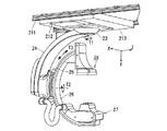
図1は、本実施形態のX線画像診断装置のハードウェア構成を示す概略図である。図2は、本実施形態のX線画像診断装置における保持装置の外観構成を示す斜視図である。 FIG. 1 is a schematic diagram illustrating a hardware configuration of the X-ray image diagnostic apparatus according to the present embodiment. FIG. 2 is a perspective view showing an external configuration of the holding device in the X-ray image diagnostic apparatus of the present embodiment.
図1及び図2は、本実施形態の天井走行式Cアームを備えるX線画像診断装置10を示す。X線画像診断装置10は、大きくは、保持装置11及びDF(Digital Fluorography)装置12から構成される。保持装置11及びDF装置12は、一般的には、検査室や治療室に設置される。
FIG.1 and FIG.2 shows the X-ray-image
なお、本実施形態に係るX線画像診断装置は、天井走行式Cアームを備えるX線画像診断装置10に限定されるものではなく、床走行式Cアームを備えるX線画像診断装置であってもよく、また、床置き式Cアームを備えるX線画像診断装置であってもよい。また、本実施形態に係るX線画像診断装置では、一例として、Cアームを備える装置により説明するが、これに限定されるものではない。例えば、X線照射装置とX線検出装置とがそれぞれ独立したアームに保持される形態であってもよく、また、Cアームを使用しないX線画像診断装置であってもよい。
Note that the X-ray image diagnostic apparatus according to the present embodiment is not limited to the X-ray image
保持装置11は、スライド機構21、鉛直軸回転機構23、懸垂アーム24、Cアーム回転機構25、Cアーム26、X線照射装置27(X線照射部)、検出装置28(検出部)、寝台29、コントローラ30、高電圧供給装置31、及び駆動制御部32を設ける。
The holding
スライド機構21は、Z軸方向レール211、X軸方向レール212、及び台車213を設ける。スライド機構21は、駆動制御部32を介したコントローラ30による制御によって、鉛直軸回転機構23、懸垂アーム24、Cアーム回転機構25、Cアーム26、X線照射装置27、及び検出装置28を一体として水平方向にスライドさせる。
The
Z軸方向レール211は、Z軸方向(天板29aの長軸方向)に延設され、天井に支持される。
The Z-
X軸方向レール212は、X軸方向(天板29aの短軸方向)に延設され、その両端のローラ(図示しない)を介してZ軸方向レール211に支持される。X軸方向レール212は、駆動制御部32を介したコントローラ30による制御によって、Z軸方向レール211上をZ軸方向に移動される。
The
台車213は、ローラ(図示しない)を介してX軸方向レール212に支持される。台車213は、駆動制御部32を介したコントローラ30による制御によって、X軸方向レール212上をX軸方向に移動される。
The
台車213を支持するX軸方向レール212がZ軸方向レール211上をZ軸方向に移動可能であり、台車213がX軸方向レール212上をX軸方向に移動可能であるので、台車213は、検査室内を、水平方向(X軸方向及びZ軸方向)に移動可能である。
Since the
鉛直軸回転機構23は、台車213に回転可能に支持される。鉛直軸回転機構23は、駆動制御部32を介したコントローラ30による制御によって、懸垂アーム24、Cアーム回転機構25、Cアーム26、X線照射装置27、及び検出装置28を一体として鉛直軸回転方向T1(図2に図示)に回転させる。
The vertical
懸垂アーム24は、鉛直軸回転機構23によって支持される。
The
Cアーム回転機構25は、懸垂アーム24に回転可能に支持される。Cアーム回転機構25は、駆動制御部32を介したコントローラ30による制御によって、Cアーム26、X線照射装置27、及び検出装置28を一体として懸垂アーム24に対する回転方向T2(図2に図示)に回転させる。
The C
Cアーム26は、Cアーム回転機構25によって支持され、X線照射装置27と検出装置28とを、被検体Pを中心に対向配置させる。Cアーム26の背面又は側面にはレール(図示しない)が設けられ、Cアーム回転機構25とCアーム26とによって挟み込まれる当該レールを介してCアーム26は、駆動制御部32を介したコントローラ30による制御によって、X線照射装置27、及び検出装置28を一体としてCアーム26の円弧方向T3(図2に図示)に円弧動させる。
The
X線照射装置27は、Cアーム26の一端に設けられる。X線照射装置27は、駆動制御部32を介したコントローラ30による制御によって、前後動が可能なように設けられる。X線照射装置27は、X線管球を有しており、高電圧供給装置31から高電圧電力の供給を受けて、高電圧電力の条件に応じて被検体Pの所定部位に向かってX線を照射する。X線照射装置27は、X線の出射側に、複数枚の鉛羽で構成されるX線照射野絞りや、シリコンゴム等で形成されハレーションを防止するために所定量の照射X線を減衰させる補償フィルタ等を設ける。また、X線照射装置27は、X線を照射する照射情報に基づいて、X線照射野絞りを調節するとともに、X線を被検体Pに照射する際の被検体Pの関心位置を特定する。
The
検出装置28は、Cアーム26の他端であってX線照射装置27の出射側に設けられる。検出装置28は、駆動制御部32を介したコントローラ30による制御によって、前後動が可能なように設けられる。検出装置28は、I.I.(Image Intensifier)−TV系であり、大きくは、I.I.28a、TVカメラ28b及びA/D(Analog to Digital)変換回路28cを備える。I.I.28aは、被検体Pを透過したX線及び直接入射されるX線を可視光に変換し、さらに、光−電子−光変換の過程で輝度の倍増を行なって感度のよい投影データを形成させる。TVカメラ28bは、CCD(Charge Coupled Device)撮像素子を用いて光学的な投影データを電気信号に変換する。A/D変換回路28cは、TVカメラ28bから出力された時系列的なアナログ信号(ビデオ信号)をデジタル信号に変換する。
The
なお、検出装置28は、平面検出器(FPD:Flat Panel Detector)を含むものであってもよい。検出装置28が平面検出器を含む場合、検出装置28は、2D状に配列された検出素子によりX線を検出して電気信号に変換する。このように、検出装置28は、被検体Pを透過したX線または直接入射されるX線を検出できさえすればよい。
The
寝台29は、床面に支持され、天板(カテーテルテーブル)29aを支持する。寝台29は、駆動制御部32を介したコントローラ30による制御によって、天板29aを水平(X、Z軸方向)動、上下(Y軸方向)動及びローリングさせる。天板29aは、被検体Pを載置可能であり、移動可能となっている。なお、保持装置11は、X線照射装置27が天板29aの下方に位置するアンダーチューブタイプである場合を説明するが、X線照射装置27が天板29aの上方に位置するオーバーチューブタイプである場合であってもよく、また、Cアームを有さないX線画像診断装置により、寝台29が天板29aを駆動するようにしてもよい。
The
コントローラ30は、図示しないCPU(Central Processing Unit)及びメモリを含んでいる。コントローラ30は、高電圧供給装置31、及び駆動制御部32等の動作を制御する。コントローラ30は、寝台29や天板29aを駆動する駆動制御部32等を制御していることにより、寝台29の位置を示す位置情報や天板29aの位置を示す位置情報を算出可能である。
The
高電圧供給装置31は、コントローラ30の制御に従って、X線照射装置27に高電圧電力を供給可能である。
The high
駆動制御部32は、コントローラ30の制御に従って、スライド機構21、鉛直軸回転機構23、Cアーム回転機構25、Cアーム26、X線照射装置27、検出装置28、及び寝台29の天板29aをそれぞれ駆動可能である。
The
DF装置12は、コンピュータをベースとして構成されており、病院基幹のLAN(Local Area Network)等のネットワークNと相互通信可能である。DF装置12は、大きくは、プロセッサとしてのCPU41、メモリ42、HDD(Hard Disc Drive)43、入力装置44、通信制御装置45、投影データ記憶部51、画像処理回路52、画像データ記憶部53、及び表示装置54等のハードウェアから構成される。CPU41は、共通信号伝送路としてのバスを介して、DF装置12を構成する各ハードウェア構成要素に相互接続されている。なお、DF装置12は、記録媒体用のドライブ(図示しない)を具備する場合もある。
The
CPU41は、医師及び検査技師等のオペレータによって入力装置44が操作等されることにより指令が入力されると、メモリ42に記憶しているプログラムを実行する。又は、CPU41は、HDD43に記憶しているプログラム、ネットワークNから転送され通信制御装置45で受信されてHDD43にインストールされたプログラム、又は記録媒体用のドライブ(図示しない)に装着された記録媒体から読み出されてHDD43にインストールされたプログラムを、メモリ42にロードして実行する。
The
メモリ42は、ROM(Read Only Memory)及びRAM(Random Access Memory)等の要素を兼ね備える構成をもつ記憶装置である。メモリ42は、IPL(Initial Program Loading)、BIOS(Basic Input/Output System)のデータを記憶したり、CPU41のワークメモリやデータの一時的な記憶に用いたりする。
The
HDD43は、磁性体を塗布又は蒸着した金属のHD(Hard Disk)が着脱不能で内蔵されている構成をもつ記憶装置である。HDD43は、DF装置12にインストールされたプログラム(アプリケーションプログラムの他、OS(Operating System)等も含まれる)や、データを記憶する。また、OSに、検査実施者に対する情報の表示にグラフィックを多用し、基礎的な操作を入力装置44によって行なうことができるGUI(Graphical User Interface)を提供させることもできる。
The
入力装置44としては、オペレータによって操作が可能なキーボード及びマウス等が挙げられ、操作に従った入力信号がCPU41に送られる。入力装置44は、大きくは、メインコンソール及びシステムコンソールによって構成される。
Examples of the
通信制御装置45は、各規格に応じた通信制御を行なう。通信制御装置45は、電話回線を通じてネットワークNに接続することができる機能を有している。DF装置12は、通信制御装置45を介してネットワークN網に接続することができる。
The communication control device 45 performs communication control according to each standard. The communication control device 45 has a function capable of connecting to the network N through a telephone line. The
投影データ記憶部51は、CPU41の制御によって、保持装置11のA/D変換回路28cから出力された投影データを記憶する。
The projection
画像処理回路52は、CPU41の制御によって、投影データ記憶部51に記憶される投影データに対して対数変換処理(LOG処理)行なって必要に応じて加算処理して、透視画像及び撮影画像(DA(Digital Angiography)画像)のデータを生成する。また、画像処理回路52は、画像データ記憶部53に記憶される透視画像及び撮影画像に対して画像処理を施す。画像処理としては、データに対する拡大/階調/空間フィルタ処理や、時系列に蓄積されたデータの最小値/最大値トレース処理、及びノイズを除去するための加算処理等が挙げられる。なお、画像処理回路52による画像処理後のデータは、表示装置54に出力されると共に、画像データ記憶部53等の記憶装置に記憶される。
Under the control of the
画像データ記憶部53は、CPU41の制御によって、画像処理回路52から出力された透視画像及び撮影画像をデータとして記憶する。
The image
表示装置54は、CPU41の制御によって、画像処理回路52によって生成される透視画像及び撮影画像のデータに、患者名等の検査情報(パラメータの文字情報及び目盛等)を合成し、合成信号をD/A(Digital to Analog)変換後、ビデオ信号として表示する。表示装置54は、画像処理回路52から出力される透視画像及び撮影画像をライブ表示するライブモニタや、画像処理回路52から出力される撮影画像を静止画像表示、また、動画再生表示する参照モニタや、FOV(Field Of View)切り替えのためのデータ等、主に保持装置11の制御を行なうためのデータを表示するシステムモニタ等を含む。
Under the control of the
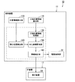
図3は、本実施形態のX線画像診断装置の機能を示すブロック図である。 FIG. 3 is a block diagram illustrating functions of the X-ray image diagnostic apparatus according to the present embodiment.
図1に示すコントローラ30(又はCPU41)がプログラムを実行することによって、図3に示すように、X線画像診断装置10(図1)は、天板位置情報算出部110、天板位置情報取得部120、位置情報算出部130、関心位置算出部140、中心座標置換部150、情報補正部160、駆動制御部32及び表示装置54として機能する。なお、各部110乃至160、及び駆動制御部32は、X線画像診断装置10の機能として保持装置11に備えられるものとして説明するが、各部110乃至160、及び駆動制御部32の全部又は一部は、X線画像診断装置10にハードウェアとして備えられるものであってもよい。また、表示装置54は、DF装置12に設けられている。
When the controller 30 (or CPU 41) shown in FIG. 1 executes the program, as shown in FIG. 3, the X-ray image diagnostic apparatus 10 (FIG. 1) includes a top board position
天板位置情報算出部110は、天板29aの位置情報を算出するようになっている。例えば、コントローラ30が駆動制御部32を制御するため、天板位置情報算出部110は、寝台29の移動位置(または、位置情報)を算出するとともに、天板29aの位置情報を算出することができるようなっている。
The top board position
天板位置情報取得部120は、天板29aの位置情報を天板位置情報算出部110から取得するようになっている。
The top plate position
位置情報算出部130は、X線照射装置27と検出装置28の位置情報または角度情報の少なくともいずれかを算出するようになっている。例えば、コントローラ30が駆動制御部32を制御するため、位置情報算出部130は、X線照射装置27と検出装置28の位置情報または角度情報の少なくともいずれかを算出することができるようなっている。
The position
関心位置算出部140は、位置情報算出部130で算出したX線照射装置27及び検出装置28の位置情報または角度情報の少なくともいずれかを取得して、被検体PにX線を照射する際の関心位置を算出することができるようになっている。
The position-of-
中心座標置換部150は、X線照射装置27及び検出装置28の位置情報または角度情報の少なくともいずれかと、天板29aの位置情報との相対的な位置関係に基づいて、関心位置算出部140において算出した関心位置を被検体Pの中心座標系の中心位置に置き換えるようになっている。
The central coordinate
情報補正部160は、天板29aの位置情報の変位を、置き換えた被検体Pの中心座標系の中心位置からの相対的な移動量として、X線照射装置27及び検出装置28の位置情報または角度情報を補正するようになっている。
The
駆動制御部32(図1参照)は、補正したX線照射装置27及び検出装置28の位置情報または角度情報に基づいて、X線照射装置27及び検出装置28を駆動するようになっている。
The drive control unit 32 (see FIG. 1) drives the
表示装置54(図1参照)は、情報補正部160で補正された被検体Pの中心座標系の中心位置を臨床角座標により表示するようになっている。
The display device 54 (see FIG. 1) displays the center position of the center coordinate system of the subject P corrected by the
本実施形態に係るX線画像診断装置10は、被検体Pを様々な角度から撮影することがあるため、天板29aを傾ける動作を行うことがある。そのため、本実施形態では、天板29aを傾ける動作のことをチルトという。また、本実施形態では、天板29aの長手方向に傾ける動作のことを長手チルトといい(図11参照)、天板29aの横手方向に傾ける動作のことを横手チルトということにする(図12参照)。
The X-ray
以上説明したように、本実施形態に係るX線画像診断装置10は、天板29aの位置情報を取得し、また、被検体PにX線を照射する際の関心位置を算出し、X線照射装置27及び検出装置28の位置情報または角度情報の少なくともいずれかと、天板29aの位置情報との相対的な位置関係に基づいて、算出した関心位置を被検体Pの中心座標系の中心位置に置き換えるようになっている。
As described above, the X-ray
これにより、本実施形態に係るX線画像診断装置10は、天板29aの位置情報の変位を、置き換えた被検体Pの中心座標系の中心位置からの相対的な移動量として、X線照射装置27及び検出装置28の位置情報または角度情報を補正することができる。
Thereby, the X-ray image
この場合、情報補正部160は、天板29aの位置情報の変位を相対的な移動量として補正する度に、被検体Pの中心座標系の中心位置を、その都度補正することができるので、臨床角座標を利用する際に、天板の位置情報も考慮した、被検体を中心とした単一座標系の位置情報による撮影を行うことができる。
In this case, the
ここで、本実施形態におけるX線画像診断装置10が行う補正方法について、2つの例を挙げて説明する。
Here, the correction method performed by the X-ray image
(第1の補正方法)
例えば、天板29aが横に移動してずれていた場合の補正方法について、図を参照しながら説明する。
(First correction method)
For example, a correction method in the case where the
図4は、本実施形態に係るX線画像診断装置10が、天板29aの位置情報の変位を、被検体Pの中心座標系の中心位置(関心位置K)からの相対的な移動量として、X線照射装置27及び検出装置28の位置情報を補正する概念を示した説明図である。
FIG. 4 shows that the X-ray
図4の説明図では、天板29aに被検体Pが載置されている。本実施形態に係るX線画像診断装置10は、X線照射装置27及び検出装置28の位置情報を取得して、被検体PにX線を照射する際の関心位置Kを算出する。
In the explanatory view of FIG. 4, the subject P is placed on the
また、本実施形態に係るX線画像診断装置10は、中心座標置換部150を備えることにより、X線照射装置27及び検出装置28の位置情報と、天板29aの位置情報との相対的な位置関係に基づいて、関心位置Kを被検体Pの中心座標系の中心位置に置き換えるようになっている。
In addition, the X-ray
ここで、被検体Pを載置した状態で、天板29aが、紙面に対して左方向(z軸方向)に距離Lだけ移動したとする。この場合、天板29aは、天板29bに移動したものとする。本実施形態に係るX線画像診断装置10は、天板位置情報算出部110により、天板29bの位置情報を取得することができるので、天板29aから天板29bへの位置情報の変位を取得することができる。
Here, it is assumed that the
また、本実施形態に係るX線画像診断装置10は、情報補正部160を備えることにより、天板29bへの位置情報の変位を、被検体Pの中心座標系の中心位置(関心位置K)からの相対的な移動量として、X線照射装置27及び検出装置28の位置情報を補正することができる。
In addition, the X-ray
この場合、天板29bの関心位置K1が、天板29aの関心位置Kに対して距離Lの差分を有しているため、X線照射装置27及び検出装置28の位置情報は、天板29bに対して、距離Lの差分が生じる。そのため、本実施形態に係るX線画像診断装置10の情報補正部160は、X線照射装置27及び検出装置28の位置情報を、相対的な移動量として、距離Lの差分を補正する。
In this case, since the position of interest K1 of the
これにより、本実施形態に係るX線画像診断装置10は、X線照射装置27及び検出装置28の位置情報を、X線を照射する際の関心位置K1に補正することができるので、天板29bの位置情報を考慮した、被検体Pを中心とした単一座標系の位置情報による撮影を行うことができる。
Thereby, the X-ray image
また、本実施形態に係るX線画像診断装置によれば、天板29bの位置情報を考慮して被検体Pを撮影することができるので、より精度の高い撮影画像データ(撮影像)を得ることができる。
In addition, according to the X-ray image diagnostic apparatus according to the present embodiment, the subject P can be imaged in consideration of the position information of the
(第2の補正方法)
次に、例えば、天板29aが起倒していた場合の補正方法について、図を参照しながら説明する。
(Second correction method)
Next, for example, a correction method when the
図5は、本実施形態に係るX線画像診断装置10が、天板29aの位置情報の変位を、被検体Pの中心座標系の中心位置(関心位置K)からの相対的な移動量として、X線照射装置27及び検出装置28の角度情報を補正する概念を示した説明図である。
FIG. 5 shows that the X-ray
図5の説明図では、天板29aに被検体Pが載置されている。本実施形態に係るX線画像診断装置10は、天板29aに対して、X線照射装置27及び検出装置28の角度情報を取得して、被検体PにX線を照射する際の関心位置Kを算出する。
In the explanatory view of FIG. 5, the subject P is placed on the
また、本実施形態に係るX線画像診断装置10は、中心座標置換部150を備えることにより、X線照射装置27及び検出装置28の角度情報と、天板29aの位置情報との相対的な位置関係に基づいて、関心位置Kを被検体Pの中心座標系の中心位置に置き換えるようになっている。
In addition, the X-ray image
ここで、被検体Pを載置した状態で、天板29aが、紙面に対して下方向に、後述するCAU(Caudal)θ(度)だけ移動したとする。この場合、例えば天板29aは、30度の角度で天板29cに移動したものとする(すなわち、長手チルトである。)。
Here, it is assumed that the
本実施形態に係るX線画像診断装置10では、天板位置情報算出部110により、天板29cの位置情報を取得することができるので、長手チルトを検出すると、天板29aから天板29cへの位置情報の変位を取得することができる。
In the X-ray
また、本実施形態に係るX線画像診断装置10は、情報補正部160を備えることにより、天板29cの位置情報の変位を、被検体Pの中心座標系の中心位置(関心位置K)からの相対的な移動量として、X線照射装置27及び検出装置28の角度情報を補正することができる。
In addition, the X-ray image
この場合、天板29cが天板29aに対してCAU30(度)の角度を有しているため、X線照射装置27及び検出装置28の角度情報は、天板29cに対して、CRA(Cranial)30(度)の差分が生じる。そのため、本実施形態に係るX線画像診断装置10の情報補正部160は、X線照射装置27及び検出装置28の角度情報を、相対的な移動量として、CAU30(度)の補正をする。
In this case, since the
これにより、本実施形態に係るX線画像診断装置10は、X線照射装置27及び検出装置28の角度情報を、X線を照射する際の関心位置Kと同じ位置に補正することができるので、天板29cの角度情報を考慮した、被検体Pを中心とした単一座標系の位置情報による撮影を行うことができる。
Thereby, the X-ray image
また、本実施形態に係るX線画像診断装置10によれば、天板29cの角度情報を考慮して被検体Pを撮影することができるので、より精度の高い撮影画像データ(撮影像)を得ることができる。
Further, according to the X-ray image
次に、3つの実施例を例示して、それぞれ詳細に説明する。 Next, three examples will be illustrated and described in detail.
<実施例1:臨床角制御動作>
本実施形態に係るX線画像診断装置10は、天板29aの位置情報を取得するようになっている。ここで、天板29aの位置情報の変位は、被検体Pを撮影する際の天板29aの移動動作に伴う移動量、天板29aの回転動作に伴う移動量、及び天板29aの位置の傾きに伴う移動量に大別することができる。
<Example 1: Clinical angle control operation>
The X-ray image
本実施形態に係るX線画像診断装置10は、天板29aのいずれの移動量であっても、コントローラ30が駆動制御部32を制御しているため、移動後の位置情報を算出することができる。
The X-ray
例えば、本実施形態に係るX線画像診断装置10は、実施例1として、天板29aの位置情報の変位を相対的に打ち消すように、X線照射装置27及び検出装置28の位置情報または角度情報を補正して、その補正後のX線照射装置27及び検出装置28の位置情報または角度情報を、被検体Pの中心座標系の中心位置とすることができる。
For example, the X-ray
図6は、本実施形態に係るX線画像診断装置10が、関心位置Kを被検体Pの中心座標系の中心位置に置き換えた臨床角座標を示した説明図である。
FIG. 6 is an explanatory diagram showing clinical angular coordinates in which the X-ray image
本実施形態に係る中心座標置換部150(図3)は、被検体PにX線を照射する際の関心位置Kと、天板29aの位置情報との相対的な位置関係に基づいて、関心位置Kを被検体Pの中心座標系の中心位置に置き換える。また、情報補正部160は、天板29aの位置情報の変位を、被検体Pの中心座標系の中心位置(関心位置K)からの相対的な移動量として、X線照射装置27及び検出装置28の位置情報または角度情報を補正する。
The central coordinate replacement unit 150 (FIG. 3) according to the present embodiment is based on the relative positional relationship between the position of interest K when the subject P is irradiated with X-rays and the position information of the
そこで、図6では、例えば、図5の説明図で説明した、補正後のX線照射装置27及び検出装置28の位置情報または角度情報により、関心位置Kを被検体Pの中心座標系の中心位置として臨床角座標により表示している。
Therefore, in FIG. 6, for example, the position of interest K is the center of the central coordinate system of the subject P based on the positional information or angle information of the corrected
すなわち、図6では、X線照射装置27及び検出装置28の角度情報に対して、CRA30(度)の差分を、X線照射装置27及び検出装置28の角度情報にCAU30(度)の補正を行い、その補正後の臨床角座標を、被検体Pの中心座標系の中心位置(基準)として表示している。
That is, in FIG. 6, the difference of CRA 30 (degrees) with respect to the angle information of the
また、図6に示すように、本実施形態では、被検体Pを照射する際に、X線照射装置27と、検出装置28とがCアーム26(図2)によって回転する回転方向を示している。
Further, as shown in FIG. 6, in this embodiment, when irradiating the subject P, the
例えば、図6(a)では、被検体Pの体軸と平行に、被検体Pの頭部から足部を見た図を示している。被検体Pの長手方向(体軸方向)を軸とした場合の右手方向(紙面に対して右方向)に回転させた角度付けを、RAO(Right Anterior Oblique)という。また、被検体Pの長手方向(体軸方向)を軸とした場合の左手方向(紙面に対して左方向)に回転させた角度付けを、LAO(Left Anterior Oblique)という。 For example, FIG. 6A shows a view of the foot from the head of the subject P in parallel with the body axis of the subject P. The angle that is rotated in the right-hand direction (rightward with respect to the paper surface) when the longitudinal direction (body axis direction) of the subject P is used as an axis is referred to as RAO (Right Antenna Oblique). In addition, the angle that is rotated in the left-hand direction (left direction with respect to the paper surface) when the longitudinal direction (body axis direction) of the subject P is used as an axis is referred to as LAO (Left Antenna Oblique).
すなわち、Cアーム26(図2)がT2方向(図2)に動作する際は、被検体Pの左手側方向をLAO方向、右手側方向をRAO方向という。 That is, when the C arm 26 (FIG. 2) operates in the T2 direction (FIG. 2), the left-hand side direction of the subject P is referred to as the LAO direction, and the right-hand side direction is referred to as the RAO direction.
また、図6(b)では、図6(a)の被検体Pの右手側から左手側を見た図を示している。被検体Pの短手方向を軸とした場合の頭部方向(紙面に対して左方向)に回転させた角度付けを、CRAという。また、被検体Pの短手方向を軸とした場合の足部方向(紙面に対して右方向)に回転させた角度付けを、CAUという。 FIG. 6B shows a view of the left hand side from the right hand side of the subject P in FIG. The angle that is rotated in the head direction (leftward with respect to the paper surface) with the short direction of the subject P as the axis is referred to as CRA. Further, the angle that is rotated in the foot direction (rightward with respect to the paper surface) with the short direction of the subject P as an axis is referred to as CAU.
すなわち、Cアーム26(図2)がT3方向(図2)に動作する際は、被検体Pの頭部方向をCRA方向、脚部方向をCAU方向という。 That is, when the C arm 26 (FIG. 2) operates in the T3 direction (FIG. 2), the head direction of the subject P is referred to as the CRA direction, and the leg direction is referred to as the CAU direction.
そして、RAO、LAO、CRA及びCAUにCアーム26を回転させた角度を付すことにより、被検体Pに対するCアーム26の位置を表すことができる。例えば、RAO10(度)、CAU10(度)、LAO20(度)、CRA20(度)などと表示することができる。
Then, the position of the
本実施形態に係るX線画像診断装置10は、補正後のX線照射装置27及び検出装置28の位置情報または角度情報により、被検体Pの中心座標系の中心位置(関心位置K)として臨床角座標により表示し、補正後の臨床角座標を基準として角度を付して表示や撮影を行うことができる。
The X-ray
したがって、本実施形態に係るX線画像診断装置10は、従来技術で示した図9から図12の天板29aの位置情報を算出し、図9から図12で示した天板29aの位置情報のずれを相対的な移動量としてそれぞれ補正した状態で、臨床角座標系を示す角度を付して表示することができる。
Therefore, the X-ray
また、本実施形態に係るX線画像診断装置10では、天板29aの位置情報を逐次算出(リアルタイムで算出)することができるので、臨床角座標系の角度を変更しても、または、天板29aの位置情報が変動しても、その都度、天板29aの位置情報の変位を補正することができる。
In the X-ray image
このように、本実施形態のX線画像診断装置10では、寝台29(図1)の駆動軸(可動軸)と、天板29aの長手チルト及び横手チルト等を考慮して、被検体Pの中心位置を座標系とした臨床角座標に補正することができる。
As described above, in the X-ray
これにより、オペレータは、入力装置44を使用して、被検体Pの撮影したい関心位置Kの角度(CRA/CAU、LAO/RAO)を変更しても、常に関心位置Kを中心位置とした状態で、天板29aの位置情報の変位を被検体Pの中心位置からの相対的な移動量として補正して臨床角制御を行うことができる。
Thus, even if the operator changes the angle (CRA / CAU, LAO / RAO) of the position of interest K to be imaged of the subject P using the
以上説明したように、実施例1では、本実施形態に係るX線画像診断装置10は、天板29aの位置情報の変位を相対的に打ち消すように、X線照射装置27及び検出装置28の位置情報または角度情報を補正して、その補正後のX線照射装置27及び検出装置28の位置情報または角度情報を、被検体Pの中心座標系の中心位置とすることができる。
As described above, in Example 1, the X-ray image
これにより、本実施形態に係るX線画像診断装置10は、被検体Pの関心位置Kを空間的に固定した状態で、被検体Pの関心位置Kに対して撮影等を行うことができる。
Thereby, the X-ray image
<実施例2:検出器正対補正動作>
次に、天板29aの位置情報の変位として、天板29aの回転動作に伴う移動量に着目して、X線検出器の回転動作に伴う移動量の補正方法について説明する。なお、基本的な構成は実施例1と同様であり、補正の対象となる天板29aの移動動作のみが異なっている。
<Example 2: Detector corrective operation>
Next, as a displacement of the position information of the
図7は、本実施形態において、X線照射装置27と検出装置28とから構成されるX線検出器の正対補正動作(これを単にX線検出器正対補正動作ともいう。)を示した説明図である(図1と図2を参照)。
FIG. 7 shows a corrective correction operation of the X-ray detector composed of the
図7では、X線照射装置27と検出装置28がCアーム26によって正対しているため、天板29aを真上方向から見た場合、X線照射装置27は検出装置28の真下に位置する。そのため、Cアーム26と検出装置28により、X線検出器正対補正動作について説明する。
In FIG. 7, since the
図7(a)は、天板29aに被検体が載置されていると仮定した場合に、天板29aが固定されていれば、被検体の関心位置Kも固定されることを示している。
FIG. 7A shows that if the subject is placed on the
図7(b)は、Cアーム26と検出装置28が、撮影動作のため被検体Pの関心位置Kを中心として移動した場合の状態を示した説明図である。Cアーム26は、回転機構と伸縮機構を備えているため、被検体の関心位置Kと相対位置関係を維持した状態で、被検体の関心位置Kを中心として回転撮影することができる。
FIG. 7B is an explanatory diagram showing a state where the C-
図7(c)は、図7(b)の位置の状態から、天板29aのみが、寝台29の回転軸(駆動軸)に従って回転動作した状態を示している。通常の撮影では、例えば、被検体の頭頂部の撮影を行いたい場合、関心位置Kを固定した状態で、医師や検査技師などの指示により、回転撮影を行うようになっている。
FIG. 7C shows a state in which only the
しかしながら、Cアーム26により回転撮影する際は、被検体の頭頂部を撮影するために、寝台29の回転軸(駆動軸)によって天板29aを動かす必要が生じることがある。この場合、天板29aに載置された被検体の関心位置Kは、天板29aの回転移動に従って移動すべきであるが、従来のX線画像診断装置では、寝台29の回転軸(駆動軸)による天板29aの位置の変位を加味(考慮)することができなかった。
However, when rotational imaging is performed with the C-
そこで、本実施形態に係るX線画像診断装置10は、図7(a)または(b)において、天板29aの位置情報を取得して、被検体の関心位置Kと、天板29aの位置情報との相対的な位置関係に基づいて、被検体の関心位置Kを被検体の中心座標系の中心位置に変換する。
Therefore, the X-ray image
図7(d)では、本実施形態に係るX線画像診断装置10は、寝台29の回転軸(駆動軸)による天板29aの位置情報の変位を(図7(c))、例えば、図7(b)における関心位置Kからの相対的な移動量として、X線照射装置27及び検出装置28の位置情報を補正する。
In FIG. 7D, the X-ray
以上説明したように、本実施形態に係るX線画像診断装置10は、被検体の関心位置Kを被検体の中心座標系の中心位置に一致させることができるので、本実施形態に係るX線画像診断装置10は、寝台29の回転軸(駆動軸)の回転角度によらず、常に正しい臨床角座標により撮影像を得ることができる。
As described above, the X-ray
<実施例3:挿入方向指示動作(オートポジショニング動作)>
本実施形態に係るX線画像診断装置10は、挿入方向指示動作(オートポジショニング動作)の機能を備えている。
<Example 3: Insertion direction instruction operation (auto positioning operation)>
The X-ray image
挿入方向指示動作(オートポジショニング動作)とは、X線照射装置27や検出装置28を保持するCアーム26や保持装置11等の任意の位置に、任意の番号に関連付けて予め位置を登録し、検査時に、医師や検査技師などのオペレータが検査に応じた番号を入力することにより、Cアーム26や保持装置11等が自動的にその番号に関連付けられた位置に配置される機能のことをいう。
The insertion direction instruction operation (auto-positioning operation) is to register a position in advance in association with an arbitrary number at an arbitrary position such as the C-
図8は、本実施形態において、本実施形態に係るX線画像診断装置10の挿入方向指示動作(オートポジショニング動作)を示す説明図である。
8, in the present embodiment, Ru illustration der the insertion direction indicating operation of the X-ray image
図8(a)は、X線照射装置27と検出装置28がCアーム26によって正対し、天板29aを真上方向から見た場合の配置を示している。天板29aを真上方向から見た場合、X線照射装置27は検出装置28の真下に位置する。そのため、Cアーム26と検出装置28により、挿入方向指示動作(オートポジショニング動作)について説明する。
FIG. 8A shows an arrangement when the
図8(a)に示すように、天板29aに被検体が載置されているとした場合、天板29aが固定されていれば、X線照射装置27と検出装置28を備えるCアーム26により、被検体の関心位置Kは固定されることを示している。
As shown in FIG. 8A, when the subject is placed on the
図8(b)は、Cアーム26と検出装置28が撮影動作において、被検体の関心位置Kを中心とした状態で、Cアーム26と検出装置28とが、一時的に移動した場合の状態を示した説明図である。なお、実施例3では、挿入方向指示動作(オートポジショニング動作)により、Cアーム26や保持装置11の位置情報を保持しているものとする。
FIG. 8B shows a state where the
図8(c)では、挿入方向指示動作(オートポジショニング動作)によって、Cアーム26や保持装置11等を所定の位置に戻す際、例えば、医師や検査技師の操作位置の関係で、天板29aの位置をずらしたことを示している。なお、天板29aは、寝台29によって可動するが、天板29aの位置は自動または手動に限定されることなく、自由に移動させることができる。
In FIG. 8C, when the C-
図8(c)に示す被検体の関心位置Kは、医師や検査技師が天板29aの位置をずらしたことにより、図8(a)や図8(b)の天板29aの位置とは異なっている。
The position of interest K of the subject shown in FIG. 8C is the position of the
図8(d)は、挿入方向指示動作(オートポジショニング動作)により、Cアーム26や保持装置11等を元の位置に戻す様子を示している。
FIG. 8D shows a state in which the
例えば、図8(a)や図8(b)において、本実施形態に係るX線画像診断装置10は、中心座標置換部150において、X線照射装置27及び検出装置28の位置情報と、天板29aの位置情報との相対的な位置関係に基づいて、関心位置Kを被検体の中心座標系の中心位置に置き換える。
For example, in FIGS. 8A and 8B, the X-ray
図8(d)では、本実施形態に係るX線画像診断装置10は、情報補正部160において、天板29aの位置情報の変位を、被検体の中心座標系の中心位置(関心位置K)からの相対的な移動量として、X線照射装置27及び検出装置28の位置情報を補正することができる。
8D, in the X-ray image
本実施形態に係るX線画像診断装置10は、情報補正部160が、X線照射装置27及び検出装置28と、天板29aとの相対的な位置関係を維持し、天板29aの位置情報の変位を、被検体の座標系の中心位置(関心位置K)からの相対的な移動量として、X線照射装置27及び検出装置28の位置情報を補正することができるので、挿入方向指示動作(オートポジショニング動作)により復元動作機能を実現することができる。
In the X-ray image
以上説明したように、本実施形態に係るX線画像診断装置10は、天板29aの位置情報を取得して、被検体にX線を照射する際の関心位置と、天板29aの位置情報との相対的な位置関係に基づいて、関心位置を被検体の中心座標系の中心位置に変換し、天板29aの位置情報の変位を、被検体の座標系の中心位置からの相対的な移動量として補正することができる。
As described above, the X-ray
また、実施例1から実施例3で例示した本実施形態に係るX線画像診断装置10によれば、被検体を中心とした中心座標系によって正確な位置情報により撮影画像データ(撮影像)を撮影することができるとともに、単一の座標系として表示させることができるので、利用効率が向上し、ユーザビリティを改善することができるとともに、手技効率化を促進することができる。
In addition, according to the X-ray image
さらに、手技中に誤って寝台29や天板29aの位置がずれた場合でも、その寝台29や天板29aの位置のずれ分を考慮(加味)した各種制御動作を行うことができるので、正確で確実な手技を継続することができる。
Furthermore, even if the position of the
本発明のいくつかの実施形態を説明したが、これらの実施形態は、例として提示したものであり、発明の範囲を限定することは意図していない。これら実施形態は、その他の様々な形態で実施されることが可能であり、発明の要旨を逸脱しない範囲で、種々の省略、置き換え、変更を行うことができる。これら実施形態やその変形は、発明の範囲や要旨に含まれると同様に、特許請求の範囲に記載された発明とその均等の範囲に含まれるものである。 Although several embodiments of the present invention have been described, these embodiments are presented by way of example and are not intended to limit the scope of the invention. These embodiments can be implemented in various other forms, and various omissions, replacements, and changes can be made without departing from the spirit of the invention. These embodiments and their modifications are included in the scope and gist of the invention, and are also included in the invention described in the claims and the equivalents thereof.
10 X線画像診断装置
11 保持装置
12 DF装置
21 スライド機構
211 Z軸方向レール
212 X軸方向レール
213 台車
23 鉛直軸回転機構
24 懸垂アーム
25 Cアーム回転機構
26 Cアーム
27 X線照射装置
28 検出装置
30 コントローラ
32 駆動制御部
44 入力装置
54 表示装置
110 天板位置情報算出部
120 天板位置情報取得部
130 位置情報算出部
140 関心位置算出部
150 中心座標置換部
160 情報補正部
DESCRIPTION OF
Claims (6)
前記X線を検出する検出部と、
被検体を載置する移動可能な天板と、
前記天板の位置情報を取得する天板位置情報取得部と、
前記X線照射部の位置情報、前記X線照射部の角度情報、前記検出部の位置情報または前記検出部の角度情報の少なくともいずれかを取得して、前記被検体に前記X線を照射する際の関心位置を算出する関心位置算出部と、
前記X線照射部の位置情報、前記X線照射部の角度情報、前記検出部の位置情報または前記検出部の角度情報の少なくともいずれかと、前記天板の位置情報との相対的な位置関係に基づいて、算出した前記関心位置を前記被検体の中心座標系の中心位置に置き換える中心座標置換部と、
前記天板の位置情報の変位を、置き換えた前記中心位置からの相対的な移動量として、前記X線照射部の位置情報、前記X線照射部の角度情報、前記検出部の位置情報または前記検出部の角度情報の少なくともいずれかを補正する情報補正部と、
補正した前記X線照射部の位置情報、前記X線照射部の角度情報、前記検出部の位置情報または前記検出部の角度情報に基づいて、前記X線照射部及び前記検出部を駆動する駆動制御部と、
を備え、
前記天板の位置情報の変位は、
前記天板の鉛直軸中心の回転動作に伴う移動量を少なくとも含み、
前記駆動制御部は、
前記天板の位置情報の変位に応じて、前記関心位置に対する前記X線照射部の相対的な位置と、前記関心位置に対する前記検出部の相対的な位置との位置関係を保持するように前記X線照射部と前記検出部とを駆動する、
X線画像診断装置。 An X-ray irradiation unit for irradiating X-rays;
A detection unit for detecting the X-ray;
A movable top plate on which the subject is placed;
A top plate position information acquisition unit for acquiring position information of the top plate;
At least one of position information of the X-ray irradiation unit, angle information of the X-ray irradiation unit, position information of the detection unit, or angle information of the detection unit is acquired, and the subject is irradiated with the X-ray. A position-of-interest calculation unit for calculating a position of interest at the time,
At least one of position information of the X-ray irradiation unit, angle information of the X-ray irradiation unit, position information of the detection unit or angle information of the detection unit, and a relative positional relationship between the position information of the top plate A center coordinate replacement unit that replaces the calculated position of interest with the center position of the center coordinate system of the subject;
The displacement of the position information of the top plate is used as a relative movement amount from the replaced center position, the position information of the X-ray irradiation unit, the angle information of the X-ray irradiation unit, the position information of the detection unit or the An information correction unit for correcting at least one of the angle information of the detection unit;
Driving to drive the X-ray irradiation unit and the detection unit based on the corrected position information of the X-ray irradiation unit, angle information of the X-ray irradiation unit, position information of the detection unit or angle information of the detection unit A control unit;
With
The displacement of the position information of the top plate is
At least the amount of movement associated with the rotational movement of the vertical axis center of the top plate,
The drive control unit
The positional relationship between the relative position of the X-ray irradiation unit with respect to the position of interest and the relative position of the detection unit with respect to the position of interest is maintained according to the displacement of the position information of the top plate. Driving the X-ray irradiation unit and the detection unit;
X-ray image diagnostic apparatus.
前記被検体を撮影する際の前記天板の位置の平行移動動作に伴う移動量をさらに含む、
請求項1に記載のX線画像診断装置。 The displacement of the position information of the top plate is
Further including a movement amount associated with a parallel movement operation of the position of the top plate when imaging the subject;
The X-ray image diagnostic apparatus according to claim 1 .
前記被検体を撮影する際の前記天板の位置の傾きに伴う移動量をさらに含む、
請求項1または2に記載のX線画像診断装置。 The displacement of the position information of the top plate is
Further including a movement amount associated with a tilt of the position of the top plate when imaging the subject;
The X-ray diagnostic imaging apparatus according to claim 1 or 2 .
さらに備える請求項1ないし3のいずれか1項に記載のX線画像診断装置。 The top-plate position information calculation part which calculates the movement position of the bed which supports the said top board, and calculates the positional information on the said top board from the movement position of the said bed is further provided in any one of Claim 1 thru | or 3. X-ray diagnostic imaging equipment.
前記X線照射部及び前記検出部の位置情報と、前記天板の位置情報との相対的な位置関係に基づいて、前記天板の位置情報の変位を、置き換えた前記中心位置からの相対的な移動量として、前記X線照射部の位置情報、前記X線照射部の角度情報、前記検出部の位置情報または前記検出部の角度情報の少なくともいずれかを補正する
請求項1ないし4のいずれか1項に記載のX線画像診断装置。 The information correction unit
Based on the relative positional relationship between the positional information of the X-ray irradiating unit and the detecting unit and the positional information of the top plate, the displacement of the positional information of the top plate is relative to the replaced center position. as Do movement amount, position information of the X-ray irradiation unit, the angle information of the X-ray irradiation unit, any of claims 1 to 4 for correcting at least one of angular information of the position information or the detector of the detection unit The X-ray diagnostic imaging apparatus of Claim 1.
前記情報補正部は、
前記相対的な移動量として、前記X線照射部の位置情報、前記X線照射部の角度情報、前記検出部の位置情報または前記検出部の角度情報のいずれかを補正する度に、補正した前記X線照射部の位置情報、前記X線照射部の角度情報、前記検出部の位置情報または前記検出部の角度情報に基づく臨床角座標を前記表示装置に表示させる
請求項1ないし5のいずれか1項に記載のX線画像診断装置。 A display device for displaying the center position of the center coordinate system of the subject;
The information correction unit
Each time the position information of the X-ray irradiation unit, the angle information of the X-ray irradiation unit, the position information of the detection unit or the angle information of the detection unit is corrected as the relative movement amount, the correction is performed. position information of the X-ray irradiation unit, the angle information of the X-ray irradiation unit, any of claims 1 to 5 to display the clinical angle coordinates based on the position information or angle information of the detection portion of the detection unit to the display device The X-ray diagnostic imaging apparatus of Claim 1.
Priority Applications (2)
| Application Number | Priority Date | Filing Date | Title |
|---|---|---|---|
| JP2014046830A JP6400307B2 (en) | 2014-03-10 | 2014-03-10 | X-ray diagnostic imaging equipment |
| US14/633,465 US9962139B2 (en) | 2014-03-10 | 2015-02-27 | X-ray image diagnostic apparatus that acquires position information associated with a table top |
Applications Claiming Priority (1)
| Application Number | Priority Date | Filing Date | Title |
|---|---|---|---|
| JP2014046830A JP6400307B2 (en) | 2014-03-10 | 2014-03-10 | X-ray diagnostic imaging equipment |
Publications (3)
| Publication Number | Publication Date |
|---|---|
| JP2015167826A JP2015167826A (en) | 2015-09-28 |
| JP2015167826A5 JP2015167826A5 (en) | 2017-03-23 |
| JP6400307B2 true JP6400307B2 (en) | 2018-10-03 |
Family
ID=54016201
Family Applications (1)
| Application Number | Title | Priority Date | Filing Date |
|---|---|---|---|
| JP2014046830A Active JP6400307B2 (en) | 2014-03-10 | 2014-03-10 | X-ray diagnostic imaging equipment |
Country Status (2)
| Country | Link |
|---|---|
| US (1) | US9962139B2 (en) |
| JP (1) | JP6400307B2 (en) |
Families Citing this family (6)
| Publication number | Priority date | Publication date | Assignee | Title |
|---|---|---|---|---|
| JP6559966B2 (en) * | 2015-02-04 | 2019-08-14 | キヤノンメディカルシステムズ株式会社 | X-ray diagnostic equipment |
| JP6687036B2 (en) * | 2015-12-09 | 2020-04-22 | 株式会社島津製作所 | X-ray equipment |
| CN206228357U (en) * | 2016-06-03 | 2017-06-09 | 北京东软医疗设备有限公司 | One kind suspention frame |
| CN107518907A (en) * | 2016-06-22 | 2017-12-29 | 沈阳东软医疗系统有限公司 | A kind of medical imaging device and its frame |
| US10973720B2 (en) * | 2017-04-07 | 2021-04-13 | Hill-Rom Services, Inc. | Image based monitoring of the state of a device |
| CN112716509B (en) * | 2020-12-24 | 2023-05-02 | 上海联影医疗科技股份有限公司 | Motion control method and system for medical equipment |
Family Cites Families (52)
| Publication number | Priority date | Publication date | Assignee | Title |
|---|---|---|---|---|
| JP3523729B2 (en) | 1995-10-27 | 2004-04-26 | 株式会社東芝 | X-ray diagnostic equipment |
| WO1998002091A1 (en) * | 1996-07-11 | 1998-01-22 | The Board Of Trustees Of The Leland Stanford Junior University | High-speed inter-modality image registration via iterative feature matching |
| US6200024B1 (en) * | 1998-11-27 | 2001-03-13 | Picker International, Inc. | Virtual C-arm robotic positioning system for use in radiographic imaging equipment |
| DE19855213C2 (en) * | 1998-11-30 | 2001-03-15 | Siemens Ag | X-ray device |
| US6463121B1 (en) * | 1999-10-13 | 2002-10-08 | General Electric Company | Interactive x-ray position and exposure control using image data as reference information |
| DE19953177A1 (en) * | 1999-11-04 | 2001-06-21 | Brainlab Ag | Method to position patient exactly for radiation therapy or surgery; involves comparing positions in landmarks in X-ray image and reconstructed image date, to determine positioning errors |
| DE10051370A1 (en) * | 2000-10-17 | 2002-05-02 | Brainlab Ag | Method and appliance for exact positioning of patient for radiation therapy and radio surgery with which only one camera is used to determine and compensate for positional error |
| JP2002143139A (en) * | 2000-11-15 | 2002-05-21 | Fuji Photo Film Co Ltd | Portable radiographic system and radiographic image detector to be used for the system |
| JP3926120B2 (en) * | 2001-02-16 | 2007-06-06 | 株式会社モリタ製作所 | X-ray imaging position setting means for an object, and X-ray imaging apparatus provided with this means |
| JP4269307B2 (en) * | 2002-10-03 | 2009-05-27 | 東芝医用システムエンジニアリング株式会社 | X-ray diagnostic equipment |
| JP4149230B2 (en) * | 2002-10-16 | 2008-09-10 | 富士フイルム株式会社 | Radiographic imaging system and radiographic image detector |
| US6935779B2 (en) * | 2002-11-29 | 2005-08-30 | Ge Medical Systems Global Technology Company, Llc | Method and apparatus for aligning an X-ray source and detector at various source to image distances |
| JP4163991B2 (en) * | 2003-04-30 | 2008-10-08 | 株式会社モリタ製作所 | X-ray CT imaging apparatus and imaging method |
| US7187792B2 (en) * | 2003-08-29 | 2007-03-06 | Accuray, Inc. | Apparatus and method for determining measure of similarity between images |
| DE102004004604B4 (en) * | 2004-01-29 | 2016-12-29 | Siemens Healthcare Gmbh | Method and imaging system for compensating patient motion during continuous shooting in medical imaging |
| JP4703119B2 (en) * | 2004-03-05 | 2011-06-15 | 株式会社東芝 | X-ray diagnostic equipment |
| EP1729647A1 (en) * | 2004-03-23 | 2006-12-13 | Koninklijke Philips Electronics N.V. | X-ray examination apparatus and method |
| US7654739B2 (en) * | 2004-07-13 | 2010-02-02 | Koninklijke Philips Electronics N.V. | X-ray equipment and method for controlling it |
| FI118356B (en) * | 2004-07-22 | 2007-10-15 | Planmeca Oy | Arrangements in connection with intraoral X-ray imaging |
| US7581885B2 (en) * | 2004-11-24 | 2009-09-01 | General Electric Company | Method and system of aligning x-ray detector for data acquisition |
| JP4868775B2 (en) * | 2005-05-31 | 2012-02-01 | 株式会社東芝 | X-ray diagnostic apparatus, image processing apparatus, and image processing program |
| DE102005032288B4 (en) * | 2005-07-11 | 2008-10-16 | Siemens Ag | X-ray system |
| US7488107B2 (en) * | 2005-08-18 | 2009-02-10 | General Electric Company | Method and apparatus to detect and correct alignment errors in x-ray systems used to generate 3D volumetric images |
| US7522701B2 (en) * | 2005-12-20 | 2009-04-21 | General Electric Company | System and method for image composition using position sensors |
| US7453984B2 (en) * | 2006-01-19 | 2008-11-18 | Carestream Health, Inc. | Real-time target confirmation for radiation therapy |
| DE102006025411B4 (en) * | 2006-05-31 | 2013-07-04 | Siemens Aktiengesellschaft | Mobile X-ray receiver for an X-ray device |
| US7620147B2 (en) * | 2006-12-13 | 2009-11-17 | Oraya Therapeutics, Inc. | Orthovoltage radiotherapy |
| US7894649B2 (en) * | 2006-11-02 | 2011-02-22 | Accuray Incorporated | Target tracking using direct target registration |
| US7744279B2 (en) * | 2006-11-02 | 2010-06-29 | Carestream Health, Inc. | Orientation sensing apparatus for radiation imaging system |
| US7627084B2 (en) * | 2007-03-30 | 2009-12-01 | General Electric Compnay | Image acquisition and processing chain for dual-energy radiography using a portable flat panel detector |
| US7572057B2 (en) * | 2007-06-21 | 2009-08-11 | Canon Kabushiki Kaisha | Radiography control apparatus and radiography control method |
| US7632014B2 (en) * | 2007-07-25 | 2009-12-15 | General Electric Company | Large X-ray detector variable centering for angulation enhancement |
| US7737427B2 (en) * | 2007-07-30 | 2010-06-15 | Fujifilm Corporation | Radiation image capturing system |
| JP5398133B2 (en) * | 2007-10-23 | 2014-01-29 | キヤノン株式会社 | X-ray imaging apparatus, control method for X-ray imaging apparatus, program, and storage medium |
| US7934869B2 (en) * | 2009-06-30 | 2011-05-03 | Mitsubishi Electric Research Labs, Inc. | Positioning an object based on aligned images of the object |
| JP2011019707A (en) * | 2009-07-15 | 2011-02-03 | Fujifilm Corp | X-ray imaging device, control method for x-ray imaging device, and program |
| CN101991427B (en) * | 2009-08-19 | 2013-02-13 | 株式会社东芝 | Medical image processing apparatus and medical image processing method |
| JP5550355B2 (en) * | 2010-01-12 | 2014-07-16 | 株式会社東芝 | X-ray diagnostic imaging equipment |
| US9541509B2 (en) * | 2010-03-26 | 2017-01-10 | Fujifilm Corporation | Radiation imaging apparatus, radiation imaging method, body movement measuring method, and body movement measuring program |
| US8174358B2 (en) * | 2010-05-24 | 2012-05-08 | General Electric Company | Handheld X-ray system interface with tracking feature |
| US8690426B2 (en) * | 2010-06-14 | 2014-04-08 | General Electric Company | Position sensing device for a portable detection device |
| DE102010038800B4 (en) * | 2010-08-02 | 2024-03-07 | Kuka Deutschland Gmbh | Medical workplace |
| JP5881290B2 (en) * | 2010-12-16 | 2016-03-09 | 株式会社東芝 | X-ray imaging system |
| KR20120093677A (en) * | 2011-02-15 | 2012-08-23 | 삼성전자주식회사 | X-ray imaging system and position calibration method of the same |
| DE102011005492B4 (en) * | 2011-03-14 | 2014-08-14 | Siemens Aktiengesellschaft | X-ray device and method for controlling the movement of an X-ray device |
| DE102011083876B4 (en) * | 2011-09-30 | 2018-12-27 | Siemens Healthcare Gmbh | Method for controlling the movement of an X-ray device and X-ray system |
| JP6104601B2 (en) * | 2012-03-06 | 2017-03-29 | 東芝メディカルシステムズ株式会社 | X-ray diagnostic imaging apparatus and control program |
| WO2013154179A1 (en) * | 2012-04-13 | 2013-10-17 | 富士フイルム株式会社 | Radiographic system and method for operating same |
| KR101431781B1 (en) * | 2012-06-20 | 2014-08-20 | 삼성전자주식회사 | X-ray image apparatus and control method for the same |
| KR101429068B1 (en) * | 2012-12-05 | 2014-08-13 | 삼성전자 주식회사 | X-ray image apparatus and control method for the same |
| KR20150052769A (en) * | 2013-11-06 | 2015-05-14 | 삼성전자주식회사 | X-ray detector, x-ray imaging apparatus and control method for the same |
| US9247920B2 (en) * | 2014-02-27 | 2016-02-02 | General Electric Company | System and method for performing bi-plane tomographic acquisitions |
-
2014
- 2014-03-10 JP JP2014046830A patent/JP6400307B2/en active Active
-
2015
- 2015-02-27 US US14/633,465 patent/US9962139B2/en active Active
Also Published As
| Publication number | Publication date |
|---|---|
| JP2015167826A (en) | 2015-09-28 |
| US9962139B2 (en) | 2018-05-08 |
| US20150250442A1 (en) | 2015-09-10 |
Similar Documents
| Publication | Publication Date | Title |
|---|---|---|
| JP6400307B2 (en) | X-ray diagnostic imaging equipment | |
| JP4703119B2 (en) | X-ray diagnostic equipment | |
| JP6466132B2 (en) | Medical image processing apparatus and X-ray image diagnostic apparatus | |
| JP6026104B2 (en) | X-ray diagnostic equipment | |
| JP5675117B2 (en) | X-ray CT apparatus and control program for X-ray CT apparatus | |
| US7845851B2 (en) | Low-dose iso-centering | |
| JP6625347B2 (en) | X-ray angiography device | |
| JP6662390B2 (en) | X-ray equipment | |
| JP2013233413A (en) | X-ray diagnostic apparatus | |
| US9888899B2 (en) | X-ray diagnostic apparatus | |
| JP2012061196A (en) | Tomographic image displaying method and apparatus | |
| JP4966120B2 (en) | X-ray angiography equipment | |
| JP2017080042A (en) | X-ray image diagnostic apparatus | |
| JP6540399B2 (en) | Radioscopic imaging apparatus | |
| US11464474B2 (en) | Medical image processing apparatus, X-ray diagnostic apparatus, and medical image processing method | |
| JP6325236B2 (en) | X-ray diagnostic equipment | |
| JP6687036B2 (en) | X-ray equipment | |
| JP2006192217A (en) | C-arm holding device and x-ray diagnostic device | |
| JP7160529B2 (en) | MEDICAL IMAGE PROCESSING APPARATUS, X-RAY DIAGNOSTIC APPARATUS, AND MEDICAL IMAGE PROCESSING METHOD | |
| JP6716196B2 (en) | X-ray equipment | |
| JP6355895B2 (en) | X-ray diagnostic equipment | |
| JP2018114361A (en) | X-ray diagnostic apparatus | |
| JP2019097769A (en) | X-ray diagnostic apparatus, positioning information creation apparatus, and x-ray diagnostic system | |
| JP2023162664A (en) | X-ray diagnostic apparatus | |
| JP2005253572A (en) | Image processor, x-ray diagnosis apparatus, medical image information system and calibration table attaching method |
Legal Events
| Date | Code | Title | Description |
|---|---|---|---|
| A711 | Notification of change in applicant |
Free format text: JAPANESE INTERMEDIATE CODE: A711 Effective date: 20160511 |
|
| A521 | Request for written amendment filed |
Free format text: JAPANESE INTERMEDIATE CODE: A523 Effective date: 20170215 |
|
| A621 | Written request for application examination |
Free format text: JAPANESE INTERMEDIATE CODE: A621 Effective date: 20170215 |
|
| A131 | Notification of reasons for refusal |
Free format text: JAPANESE INTERMEDIATE CODE: A131 Effective date: 20171114 |
|
| A977 | Report on retrieval |
Free format text: JAPANESE INTERMEDIATE CODE: A971007 Effective date: 20171110 |
|
| A521 | Request for written amendment filed |
Free format text: JAPANESE INTERMEDIATE CODE: A523 Effective date: 20171222 |
|
| A131 | Notification of reasons for refusal |
Free format text: JAPANESE INTERMEDIATE CODE: A131 Effective date: 20180327 |
|
| A521 | Request for written amendment filed |
Free format text: JAPANESE INTERMEDIATE CODE: A523 Effective date: 20180528 |
|
| TRDD | Decision of grant or rejection written | ||
| A01 | Written decision to grant a patent or to grant a registration (utility model) |
Free format text: JAPANESE INTERMEDIATE CODE: A01 Effective date: 20180807 |
|
| A61 | First payment of annual fees (during grant procedure) |
Free format text: JAPANESE INTERMEDIATE CODE: A61 Effective date: 20180905 |
|
| R150 | Certificate of patent or registration of utility model |
Ref document number: 6400307 Country of ref document: JP Free format text: JAPANESE INTERMEDIATE CODE: R150 |