JP2014145604A - Operation system - Google Patents
Operation system Download PDFInfo
- Publication number
- JP2014145604A JP2014145604A JP2013012874A JP2013012874A JP2014145604A JP 2014145604 A JP2014145604 A JP 2014145604A JP 2013012874 A JP2013012874 A JP 2013012874A JP 2013012874 A JP2013012874 A JP 2013012874A JP 2014145604 A JP2014145604 A JP 2014145604A
- Authority
- JP
- Japan
- Prior art keywords
- unit
- main body
- drive mechanism
- probe
- operator
- Prior art date
- Legal status (The legal status is an assumption and is not a legal conclusion. Google has not performed a legal analysis and makes no representation as to the accuracy of the status listed.)
- Granted
Links
Images


Landscapes
- Length Measuring Devices With Unspecified Measuring Means (AREA)
Abstract
Description
本発明は、操作システムに関し、例えば三次元測定機等を備える操作システムに関する。 The present invention relates to an operation system, for example, an operation system including a coordinate measuring machine or the like.
工作機械で被加工物を加工したり、測定機で被測定物を測定したりするとき、工作機械や測定機等の本体部を操作部によって遠隔操作することがある。このとき、被加工物や被測定物を目視し易いように、操作部を持った操作者が本体部の周辺を移動するが、本体部に対する操作部の位置が変わっても、操作者が操作部を操作する方向と被加工物や被測定物が移動する方向とが一致することが好ましい。 When processing a workpiece with a machine tool or measuring a workpiece with a measuring machine, the main body of the machine tool, the measuring machine, or the like may be remotely operated by an operation unit. At this time, the operator with the operation unit moves around the main unit so that the work piece and the measurement target can be easily seen, but even if the position of the operation unit with respect to the main unit changes, the operator can operate It is preferable that the direction in which the part is operated coincides with the direction in which the workpiece or the measurement object moves.
そこで、特許文献1の遠隔操作装置は、被測定物の移動方向と操作者が操作部を操作する方向とを一致させるための切替スイッチを操作部に備えている。
In view of this, the remote operation device of
特許文献1の遠隔操作装置は、本体部に対する操作部の位置に応じて、操作者が切替スイッチを適宜切り替える必要があり、操作が煩雑になる上、人的な誤動作につながる恐れがある。
In the remote control device of
本発明は、このような問題点を解決するためになされたものであり、簡単な操作で本体部を遠隔操作できる操作システムを提供することを目的とする。 The present invention has been made to solve such problems, and an object of the present invention is to provide an operation system capable of remotely operating the main body by a simple operation.
本発明の一形態に係る操作システムは、部材の駆動機構を有する本体部と、前記駆動機構を遠隔操作するために操作者が操作する操作部と、前記本体部に対する前記操作部の位置を検出する検出部と、前記検出部の検出結果に基づいて、前記部材の移動方向と操作者が前記操作部を操作する方向とを一致させる制御部を備える。 An operation system according to an aspect of the present invention includes a main body having a member drive mechanism, an operation section operated by an operator to remotely operate the drive mechanism, and a position of the operation section with respect to the main body. And a control unit that matches the moving direction of the member with the direction in which the operator operates the operation unit based on the detection result of the detection unit.
上述の操作システムにおいて、前記検出部は、前記本体部に設けられた周辺情報取得部を有し、前記周辺情報取得部が取得した前記本体部の周辺情報に基づいて、前記本体部に対する前記操作部の位置を検出することが好ましい。 In the operation system described above, the detection unit includes a peripheral information acquisition unit provided in the main body unit, and the operation on the main body unit based on the peripheral information of the main body unit acquired by the peripheral information acquisition unit. It is preferable to detect the position of the part.
上述の操作システムにおいて、前記検出部は、前記操作部に設けられた位置情報取得部を有し、前記位置情報取得部が取得した前記操作部の位置情報に基づいて、前記本体部に対する前記操作部の位置を検出することが好ましい。 In the operation system described above, the detection unit includes a position information acquisition unit provided in the operation unit, and the operation on the main body unit based on the position information of the operation unit acquired by the position information acquisition unit. It is preferable to detect the position of the part.
上述の操作システムにおいて、前記検出部は、前記本体部及び前記操作部のいずれか一方に設けられ、識別信号を出射する出射部と、他方に設けられ、前記出射部の識別信号を受信する受信部を有し、前記受信部の受信結果に基づいて、前記本体部に対する前記操作部の位置を検出することが好ましい。 In the above-described operation system, the detection unit is provided in one of the main body unit and the operation unit and emits an identification signal, and is provided in the other and receives the identification signal of the emission unit. It is preferable that a position of the operation unit with respect to the main body unit is detected based on a reception result of the reception unit.
上述の操作システムにおいて、前記本体部は、プローブと、前記プローブと被測定物とを相対的に移動させる駆動機構を備える三次元測定機であることが好ましい。 In the above-described operation system, it is preferable that the main body is a coordinate measuring machine including a probe and a drive mechanism that relatively moves the probe and the object to be measured.
本発明によれば、簡単な操作で本体部を遠隔操作できる操作システムを提供することを目的とする。 An object of the present invention is to provide an operation system capable of remotely operating a main body by a simple operation.
以下、本発明を実施するための最良の形態について、添付図面を参照しながら説明する。但し、本発明が以下の実施の形態に限定される訳ではない。また、説明を明確にするため、以下の記載及び図面は、適宜、簡略化されている。 The best mode for carrying out the present invention will be described below with reference to the accompanying drawings. However, the present invention is not limited to the following embodiment. In addition, for clarity of explanation, the following description and drawings are simplified as appropriate.
<実施の形態1>
先ず、本実施の形態の操作システムの基本構成を説明する。図1は、本実施の形態の操作システム1を概略的に示す斜視図である。図2は、本実施の形態の操作システム1の制御系ブロック図である。
<
First, the basic configuration of the operation system according to the present embodiment will be described. FIG. 1 is a perspective view schematically showing an
図1及び図2に示すように、操作システム1は、本体部2、操作部3及びホストコンピュータ4を備えている。本体部2は、部材を移動させるための駆動機構を有する。本実施の形態の本体部2は、三次元測定機である。本体部2は、基台5、門型フレーム6、プローブ7、X方向駆動機構8、Y方向駆動機構9、Z方向駆動機構10、検出部11及び制御装置12を備えている。
As shown in FIGS. 1 and 2, the
なお、本実施の形態においては、基台5の上面で互いに直交する二方向をそれぞれX方向(左右方向)、Y方向(前後方向)とする。また、基台5の上面に垂直な方向をZ方向(上下方向)とする。
In the present embodiment, two directions orthogonal to each other on the upper surface of the
基台5は門型フレーム6等を支持する。ここで、基台5は、積層ゴム等の除振台上に配置されていることが好ましい。基台5におけるZ方向の+側の面は、被測定物を載せるために精密平坦加工されている。門型フレーム6は、基台5をX方向に跨ぐように配置されており、基台5に対してY方向に移動可能な構成とされている。プローブ7は、駆動機構で移動する部材の一例であり、例えば被測定物に接触し、接触信号をホストコンピュータ4に出力する。但し、プローブ7は、非接触式のプローブでもよい。
The
X方向駆動機構8は、プローブ7をX方向に移動させる。本実施の形態のX方向駆動機構8は、門型フレーム6内に収容されている。Y方向駆動機構9は、門型フレーム6をY方向に移動させる。本実施の形態のY方向駆動機構9は、基台5内に収容されている。Z方向駆動機構10は、プローブ7をZ方向に移動させる。本実施の形態のZ方向駆動機構10は、門型フレーム6内に収容されている。但し、X方向駆動機構8、Y方向駆動機構9及びZ方向駆動機構10は、プローブ7を良好に移動されることができれば、構成は特に限定されない。
The X
検出部11は、本体部2に対する操作部3の位置を検出する。検出部11は、本体部2の周辺情報を取得する周辺情報取得部11aを備えている。周辺情報取得部11aは、例えば画像センサを備えている。周辺情報取得部11aは、本体部2に設けられている。
The
ここで、図3は、周辺情報取得部11aの配置を示す図である。図3に示すように、周辺情報取得部11aは、本体部2の基台5の四辺に夫々設けられている。例えば、周辺情報取得部11aは、Z方向から見て本体部2の基台5におけるX方向の+側の辺の略中央部、本体部2の基台5におけるX方向の−側の辺の略中央部、本体部2の基台5におけるY方向の+側の辺の略中央部、及び本体部2の基台5におけるY方向の−側の辺の略中央部に配置されている。
Here, FIG. 3 is a diagram illustrating an arrangement of the peripheral
これらの周辺情報取得部11aが取得した周辺情報に基づいて、検出部11は操作者や操作部3を検出し、本体部2に対する操作部3の位置を検出する。検出部11が操作者や操作部3を検出する方法は、一般的な方法を用いることができ、例えば検出部11は、取得した周辺情報を画像処理して特徴点を抽出し、操作者や操作部3を検出し、グローバル座標系等の基準座標を用いて本体部2に対する操作部3の位置を検出する。つまり、検出部11は、本体部2に対して操作部3がX方向の+−どちらの側に在るのか、Y方向の+−どちらの側に在るのかを検出する。言い換えると、検出部11は、操作者が本体部2に対して奥側、手前側、左側及び右側のいずれの側で操作部3を操作しているのかを検出する。検出部11は、検出信号を制御装置12に出力する。
Based on the peripheral information acquired by the peripheral
但し、本実施の形態では、周辺情報取得部11aを用いて本体部2に対する操作部3の位置を検出したが、本体部2に対する操作部3の位置を検出することができれば、手段は特に限定されない。また、周辺情報取得部11aの配置は、上述の限りでなく、本体部2に対する操作部3の位置を検出することができればよく、例えば基台5の四隅に配置されてもよい。
However, in the present embodiment, the position of the
制御装置12は、詳細は後述するが、操作部3から入力される操作信号及び検出部11から入力される検出信号に基づいて、X方向駆動機構8、Y方向駆動機構9及びZ方向駆動機構10の制御信号を夫々生成し、当該制御信号に基づいてX方向駆動機構8、Y方向駆動機構9及びZ方向駆動機構10を夫々制御する。
Although details will be described later, the
操作部3は、X方向駆動機構8、Y方向駆動機構9及びZ方向駆動機構10を遠隔操作するために操作者が操作する。ここで、図4は、本実施の形態の操作部3を概略的に示す図である。図4に示すように、操作部3は、X方向駆動機構8及びY方向駆動機構9を操作するための操作レバー13、及びZ方向駆動機構10を操作するための操作レバー14を備えている。操作者が操作レバー13及び14を傾動させることで、操作部3はX方向駆動機構8、Y方向駆動機構9及びZ方向駆動機構10の操作信号を生成し、当該操作信号を制御装置12に出力する。なお、操作部3の操作信号の処理については後述する。
The
ホストコンピュータ4は、プローブ7から入力される接触信号に基づいて、被測定物の位置及び座標の一方又は両方を測定する。
The
次に、本実施の形態の操作システム1における、制御装置12での操作信号の処理動作を説明する。制御装置12は、入力される検出信号に基づいて、プローブ8の移動方向と操作レバー13の操作方向とが略一致するように、操作信号を処理する。ここで、以下の説明における前後左右方向は、操作者が操作部3を操作する際に当該操作部3をZ方向から見た方向である。
Next, an operation signal processing operation in the
本体部2に対して操作部3がX方向の−側に在る旨の検出信号が入力されたとき、操作者が操作レバー13を前側に傾動させると、プローブ7をX方向の+側に移動させるべくX方向駆動機構8が駆動し、操作者が操作レバー13を後側に傾動させると、プローブ7をX方向の−側に移動させるべくX方向駆動機構8が駆動するように、制御装置12が操作信号を処理する。そして、操作者が操作レバー13を左側に傾動させると、プローブ7をY方向の+側に移動させるべくY方向駆動機構9が駆動し、操作者が操作レバー13を右側に傾動させると、プローブ7をY方向の−側に移動させるべくY方向駆動機構9が駆動するように、制御装置12が操作信号を処理する。
When a detection signal indicating that the
本体部2に対して操作部3がX方向の+側に在る旨の検出信号が入力されたとき、操作者が操作レバー13を前側に傾動させると、プローブ7をX方向の−側に移動させるべくX方向駆動機構8が駆動し、操作者が操作レバー13を後側に傾動させると、プローブ7をX方向の+側に移動させるべくX方向駆動機構8が駆動するように、制御装置12が操作信号を処理する。そして、操作者が操作レバー13を左側に傾動させると、プローブ7をY方向の−側に移動させるべくY方向駆動機構9が駆動し、操作者が操作レバー13を右側に傾動させると、プローブ7をY方向の+側に移動させるべくY方向駆動機構9が駆動するように、制御装置12が操作信号を処理する。
When a detection signal indicating that the
本体部2に対して操作部3がY方向の−側に在る旨の検出信号が入力されたとき、操作者が操作レバー13を前側に傾動させると、プローブ7をY方向の+側に移動させるべくY方向駆動機構9が駆動し、操作者が操作レバー13を後側に傾動させると、プローブ7をY方向の−側に移動させるべくY方向駆動機構9が駆動するように、制御装置12が操作信号を処理する。そして、操作者が操作レバー13を左側に傾動させると、プローブ7をX方向の−側に移動させるべくX方向駆動機構8が駆動し、操作者が操作レバー13を右側に傾動させると、プローブ7をX方向の+側に移動させるべくX方向駆動機構8が駆動するように、制御装置12が操作信号を処理する。
When a detection signal indicating that the
本体部2に対して操作部3がY方向の+側に在る旨の検出信号が入力されたとき、操作者が操作レバー13を前側に傾動させると、プローブ7をY方向の−側に移動させるべくY方向駆動機構9が駆動し、操作者が操作レバー13を後側に傾動させると、プローブ7をY方向の+側に移動させるべくY方向駆動機構9が駆動するように、制御装置12が操作信号を処理する。そして、操作者が操作レバー13を左側に傾動させると、プローブ7をX方向の+側に移動させるべくX方向駆動機構8が駆動し、操作者が操作レバー13を右側に傾動させると、プローブ7をX方向の−側に移動させるべくX方向駆動機構8が駆動するように、制御装置12が操作信号を処理する。
When a detection signal indicating that the
一方、操作者が操作レバー14を前側に傾動させると、プローブ7をZ方向の+側に移動させるべくZ方向駆動機構10が駆動し、操作者が操作レバー14を後側に傾動させると、プローブ7をZ方向の−側に移動させるべくZ方向駆動機構10が駆動するように、制御装置12が操作信号を処理する。
On the other hand, when the operator tilts the
このような操作システム1は、本体部2に対する操作部3の位置を検出し、検出結果に基づいて、プローブ7の移動方向と当該プローブ7を移動させるべく操作者が操作部3を操作する方向とを一致させる。つまり、操作者が本体部2に向かって立っている状態において、プローブ7の移動方向と操作者が操作部3を操作する方向とを一致させる。そのため、操作者は特別な操作を行わなくても、本体部2に対する操作者の立ち位置に対応するようにプローブ7を移動させることができ、簡単な操作で本体部を遠隔操作でき、しかも操作者の誤操作を防ぐことができる。
Such an
<実施の形態2>
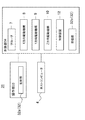
図5は、本実施の形態の操作システム21の制御系ブロック図である。なお、以下の説明において、重複する説明は省略し、同一の要素には同一の符号を用いて説明する。
<
FIG. 5 is a control system block diagram of the
図5に示すように、本実施の形態の検出部22は、操作部23に備えられている。この検出部22も、本体部24に対する操作部23の位置を検出する。検出部22は、操作部23の位置情報を取得する位置情報取得部22aを備えている。位置情報取得部22aは、例えばGPS(Global Positioning System)を備えている。
As shown in FIG. 5, the
位置情報取得部22aが取得した位置情報及び予め設定された本体部24の位置情報に基づいて、検出部22は本体部24に対する操作部23の位置を検出する。つまり、検出部22は、本体部24に対して操作部23がX方向の+−どちらの側に在るのか、Y方向の+−どちらの側に在るのかを検出する。言い換えると、検出部22は、操作者が本体部24に対して奥側、手前側、左側及び右側のいずれの側で操作部3を操作しているのかを検出する。
The
このような操作システム21も、本体部24に対する操作部23の位置を検出し、検出結果に基づいて、プローブ7の移動方向と当該プローブ7を移動させるべく操作者が操作部23を操作する方向とを一致させる。そのため、操作者は特別な操作を行わなくても、本体部24に対する操作者の立ち位置に対応するようにプローブ7を移動させることができ、簡単な操作で本体部24を遠隔操作でき、しかも操作者の誤操作を防ぐことができる。
Such an
<実施の形態3>
図6は、本実施の形態の操作システム31の制御系ブロック図である。なお、以下の説明において、重複する説明は省略し、同一の要素には同一の符号を用いて説明する。
<
FIG. 6 is a control system block diagram of the
図6に示すように、本実施の形態の検出部32は、出射部32a及び受信部32bを備えている。出射部32aは、操作部33に備えられている。この出射部32aは、例えば操作部33の識別信号を出射する。
As shown in FIG. 6, the
受信部32bは、本体部34に備えられている。例えば受信部32bは、本体部34の基台5の四辺に夫々設けられている。但し、受信部32bは、本体部34の周辺の出射部32aの識別信号を受信できるように配置されていればよく、例えば基台5の四隅に配置されてもよい。
The
この受信部32bは、出射部32aから出射された識別信号を受信し、受信した識別信号に基づいて、本体部34に対する操作部33の位置を検出し、検出信号を制御装置12に出力する。つまり、本体部34の基台5の四辺に設けた受信部32bの内、いずれの受信部32bが識別信号を受信したかに基づいて、操作者が本体部34に対して奥側、手前側、左側及び右側のいずれの側で操作部33を操作しているのかを検出する。
The
このような操作システム31も、本体部34に対する操作部33の位置を検出し、検出結果に基づいて、プローブ7の移動方向と当該プローブ7を移動させるべく操作者が操作部33を操作する方向とを一致させる。そのため、操作者は特別な操作を行わなくても、本体部34に対する操作者の立ち位置に対応するようにプローブ7を移動させることができ、簡単な操作で本体部34を遠隔操作でき、しかも操作者の誤操作を防ぐことができる。
Such an
なお、本実施の形態では、出射部32aを操作部33に備え、受信部32bを本体部34に備えたが、逆の構成でもよい。このとき、本体部34の基台5の四辺に夫々、異なる識別信号を出射する出射部32aを設け、出射部32aから出射した識別信号を受信部32bが受信したとき、いずれの出射部32aからの識別信号を受信したのかを識別することで、本体部34に対する操作部33の位置を検出するとよい。
In the present embodiment, the
本発明は上記実施の形態に限られたものではなく、趣旨を逸脱しない範囲で適宜変更することが可能である。 The present invention is not limited to the above-described embodiment, and can be changed as appropriate without departing from the spirit of the present invention.
1 操作システム
2 本体部
3 操作部
4 ホストコンピュータ
5 基台
6 門型フレーム
7 プローブ
8 X方向駆動機構
9 Y方向駆動機構
10 Z方向駆動機構
11 検出部、11a 周辺情報取得部
12 制御装置
13、14 操作レバー
21 操作システム
22 検出部、22a 位置情報取得部
23 操作部
31 操作システム
32 検出部、32a 出射部、32b 受信部
33 操作部
34 本体部
DESCRIPTION OF
Claims (5)
前記駆動機構を遠隔操作するために操作者が操作する操作部と、
前記本体部に対する前記操作部の位置を検出する検出部と、
前記検出部の検出結果に基づいて、前記部材の移動方向と操作者が前記操作部を操作する方向とを一致させる制御部と、
を備える操作システム。 A main body having a member drive mechanism;
An operation unit operated by an operator to remotely operate the drive mechanism;
A detection unit for detecting a position of the operation unit with respect to the main body unit;
Based on the detection result of the detection unit, a control unit that matches the movement direction of the member with the direction in which the operator operates the operation unit,
An operation system comprising:
前記本体部及び前記操作部のいずれか一方に設けられ、識別信号を出射する出射部と、
他方に設けられ、前記出射部の識別信号を受信する受信部と、
を有し、
前記受信部の受信結果に基づいて、前記本体部に対する前記操作部の位置を検出する請求項1に記載の操作システム。 The detector is
An emission part that is provided on either the main body part or the operation part and emits an identification signal;
A receiving unit provided on the other side for receiving an identification signal of the emitting unit;
Have
The operation system according to claim 1, wherein a position of the operation unit with respect to the main body unit is detected based on a reception result of the reception unit.
プローブと、
前記プローブと被測定物とを相対的に移動させる駆動機構と、
を備える三次元測定機である請求項1乃至4のいずれか1項に記載の操作システム。 The body part is
A probe,
A drive mechanism for relatively moving the probe and the object to be measured;
The operation system according to claim 1, wherein the operation system is a three-dimensional measuring machine.
Priority Applications (1)
| Application Number | Priority Date | Filing Date | Title |
|---|---|---|---|
| JP2013012874A JP6154615B2 (en) | 2013-01-28 | 2013-01-28 | Operation system |
Applications Claiming Priority (1)
| Application Number | Priority Date | Filing Date | Title |
|---|---|---|---|
| JP2013012874A JP6154615B2 (en) | 2013-01-28 | 2013-01-28 | Operation system |
Publications (2)
| Publication Number | Publication Date |
|---|---|
| JP2014145604A true JP2014145604A (en) | 2014-08-14 |
| JP6154615B2 JP6154615B2 (en) | 2017-06-28 |
Family
ID=51425972
Family Applications (1)
| Application Number | Title | Priority Date | Filing Date |
|---|---|---|---|
| JP2013012874A Active JP6154615B2 (en) | 2013-01-28 | 2013-01-28 | Operation system |
Country Status (1)
| Country | Link |
|---|---|
| JP (1) | JP6154615B2 (en) |
Cited By (4)
| Publication number | Priority date | Publication date | Assignee | Title |
|---|---|---|---|---|
| JP2017520843A (en) * | 2015-05-28 | 2017-07-27 | 小米科技有限責任公司Xiaomi Inc. | Flight control method, flight control device, and electronic apparatus |
| WO2019172406A1 (en) * | 2018-03-09 | 2019-09-12 | 株式会社タダノ | Remote operation terminal and mobile crane comprising remote operation terminal |
| JP2019172434A (en) * | 2018-03-28 | 2019-10-10 | 株式会社タダノ | Remote control terminal and work vehicle comprising the same |
| JP2019177978A (en) * | 2018-03-30 | 2019-10-17 | 株式会社タダノ | Remote operation terminal and work vehicle comprising remote operation terminal |
Citations (5)
| Publication number | Priority date | Publication date | Assignee | Title |
|---|---|---|---|---|
| JPS5931008U (en) * | 1982-08-23 | 1984-02-27 | 株式会社ミツトヨ | Remote control device for coordinate measuring machine |
| JP2007122580A (en) * | 2005-10-31 | 2007-05-17 | Equos Research Co Ltd | Vehicle and remote control device |
| JP2007265288A (en) * | 2006-03-29 | 2007-10-11 | Equos Research Co Ltd | Vehicle and remote operation device |
| US20110119025A1 (en) * | 2009-11-18 | 2011-05-19 | Hexagon Metrology, Inc. | Manipulable aid for dimensional metrology |
| JP2011115884A (en) * | 2009-12-02 | 2011-06-16 | Shima Seiki Mfg Ltd | Cutter |
-
2013
- 2013-01-28 JP JP2013012874A patent/JP6154615B2/en active Active
Patent Citations (5)
| Publication number | Priority date | Publication date | Assignee | Title |
|---|---|---|---|---|
| JPS5931008U (en) * | 1982-08-23 | 1984-02-27 | 株式会社ミツトヨ | Remote control device for coordinate measuring machine |
| JP2007122580A (en) * | 2005-10-31 | 2007-05-17 | Equos Research Co Ltd | Vehicle and remote control device |
| JP2007265288A (en) * | 2006-03-29 | 2007-10-11 | Equos Research Co Ltd | Vehicle and remote operation device |
| US20110119025A1 (en) * | 2009-11-18 | 2011-05-19 | Hexagon Metrology, Inc. | Manipulable aid for dimensional metrology |
| JP2011115884A (en) * | 2009-12-02 | 2011-06-16 | Shima Seiki Mfg Ltd | Cutter |
Cited By (11)
| Publication number | Priority date | Publication date | Assignee | Title |
|---|---|---|---|---|
| JP2017520843A (en) * | 2015-05-28 | 2017-07-27 | 小米科技有限責任公司Xiaomi Inc. | Flight control method, flight control device, and electronic apparatus |
| US10569874B2 (en) | 2015-05-28 | 2020-02-25 | Xiaomi Inc. | Flight control method and apparatus |
| WO2019172406A1 (en) * | 2018-03-09 | 2019-09-12 | 株式会社タダノ | Remote operation terminal and mobile crane comprising remote operation terminal |
| JP2019156527A (en) * | 2018-03-09 | 2019-09-19 | 株式会社タダノ | Remote control terminal and mobile crane comprising remote control terminal |
| CN111801294A (en) * | 2018-03-09 | 2020-10-20 | 株式会社多田野 | Remote operation terminal and mobile crane provided with same |
| JP7087475B2 (en) | 2018-03-09 | 2022-06-21 | 株式会社タダノ | Mobile crane with remote control terminal and remote control terminal |
| CN111801294B (en) * | 2018-03-09 | 2022-06-21 | 株式会社多田野 | Remote operation terminal and mobile crane provided with same |
| JP2019172434A (en) * | 2018-03-28 | 2019-10-10 | 株式会社タダノ | Remote control terminal and work vehicle comprising the same |
| JP7167464B2 (en) | 2018-03-28 | 2022-11-09 | 株式会社タダノ | Remote control terminal and work vehicle equipped with remote control terminal |
| JP2019177978A (en) * | 2018-03-30 | 2019-10-17 | 株式会社タダノ | Remote operation terminal and work vehicle comprising remote operation terminal |
| JP7167469B2 (en) | 2018-03-30 | 2022-11-09 | 株式会社タダノ | Remote control terminal and work vehicle equipped with remote control terminal |
Also Published As
| Publication number | Publication date |
|---|---|
| JP6154615B2 (en) | 2017-06-28 |
Similar Documents
| Publication | Publication Date | Title |
|---|---|---|
| US10546167B2 (en) | System and method of operating a manufacturing cell | |
| AU2014235971B2 (en) | Noncontact measuring device | |
| US10940573B2 (en) | Hand-held tool system | |
| JP6154615B2 (en) | Operation system | |
| US8169604B2 (en) | Parameter detection system | |
| US8629987B2 (en) | Optical-type position detecting device, hand apparatus, and touch panel | |
| US9862097B2 (en) | Industrial robot system having sensor assembly | |
| US8650767B2 (en) | Coordinates measuring head unit and coordinates measuring machine | |
| CN106535766A (en) | Method and device for positioning an emitter | |
| US9618649B2 (en) | Detecting an overall dimension of a plate-shaped workpiece by a non-contact sensor | |
| WO2005116809A3 (en) | System and method for operating in virtual 3d space and system for selecting an operation via a visualizing system | |
| JP2013188858A (en) | Fastening tool, fastening position management system, and fastening position detection method | |
| JP2011048467A (en) | Machining system | |
| JP2013025478A (en) | Work detection system | |
| CN104316012A (en) | Industrial robot for measuring size of large part | |
| CN110385695A (en) | Checking job robot system and Work robot | |
| JP4431446B2 (en) | Self-propelled robot | |
| EP3434411B1 (en) | Programmable device provided in a production environment for assisting an operator | |
| JP5516974B2 (en) | Vision sensor mounting apparatus and method | |
| WO2012111510A1 (en) | Position detection device | |
| JP2019174177A (en) | Movement amount detector | |
| KR20140008658A (en) | Welding point aautomatic recognition system and recognition method | |
| KR101799280B1 (en) | High-precision 3D meαsuring system αnd the method thereof | |
| KR101741498B1 (en) | A device for measuring performance of a remote controlling system | |
| JP2009008533A (en) | Optical measuring system |
Legal Events
| Date | Code | Title | Description |
|---|---|---|---|
| A621 | Written request for application examination |
Free format text: JAPANESE INTERMEDIATE CODE: A621 Effective date: 20151208 |
|
| A977 | Report on retrieval |
Free format text: JAPANESE INTERMEDIATE CODE: A971007 Effective date: 20161014 |
|
| A131 | Notification of reasons for refusal |
Free format text: JAPANESE INTERMEDIATE CODE: A131 Effective date: 20161018 |
|
| A521 | Request for written amendment filed |
Free format text: JAPANESE INTERMEDIATE CODE: A523 Effective date: 20161216 |
|
| TRDD | Decision of grant or rejection written | ||
| A01 | Written decision to grant a patent or to grant a registration (utility model) |
Free format text: JAPANESE INTERMEDIATE CODE: A01 Effective date: 20170516 |
|
| A61 | First payment of annual fees (during grant procedure) |
Free format text: JAPANESE INTERMEDIATE CODE: A61 Effective date: 20170602 |
|
| R150 | Certificate of patent or registration of utility model |
Ref document number: 6154615 Country of ref document: JP Free format text: JAPANESE INTERMEDIATE CODE: R150 |
|
| R250 | Receipt of annual fees |
Free format text: JAPANESE INTERMEDIATE CODE: R250 |
|
| R250 | Receipt of annual fees |
Free format text: JAPANESE INTERMEDIATE CODE: R250 |