JP2014085861A - Display system, terminal device, display device, display system control method, terminal device control method and display device control method - Google Patents
Display system, terminal device, display device, display system control method, terminal device control method and display device control method Download PDFInfo
- Publication number
- JP2014085861A JP2014085861A JP2012234581A JP2012234581A JP2014085861A JP 2014085861 A JP2014085861 A JP 2014085861A JP 2012234581 A JP2012234581 A JP 2012234581A JP 2012234581 A JP2012234581 A JP 2012234581A JP 2014085861 A JP2014085861 A JP 2014085861A
- Authority
- JP
- Japan
- Prior art keywords
- image
- processor
- image signal
- display
- unit
- Prior art date
- Legal status (The legal status is an assumption and is not a legal conclusion. Google has not performed a legal analysis and makes no representation as to the accuracy of the status listed.)
- Pending
Links
- 238000000034 method Methods 0.000 title claims abstract description 123
- 238000007781 pre-processing Methods 0.000 claims abstract description 23
- 230000008569 process Effects 0.000 claims description 77
- 230000004044 response Effects 0.000 claims description 42
- 230000005540 biological transmission Effects 0.000 claims description 18
- APTZNLHMIGJTEW-UHFFFAOYSA-N pyraflufen-ethyl Chemical compound C1=C(Cl)C(OCC(=O)OCC)=CC(C=2C(=C(OC(F)F)N(C)N=2)Cl)=C1F APTZNLHMIGJTEW-UHFFFAOYSA-N 0.000 claims description 5
- 239000002131 composite material Substances 0.000 description 16
- 230000015572 biosynthetic process Effects 0.000 description 13
- 230000006870 function Effects 0.000 description 13
- 238000003786 synthesis reaction Methods 0.000 description 13
- 238000006243 chemical reaction Methods 0.000 description 12
- 238000001514 detection method Methods 0.000 description 12
- 230000003111 delayed effect Effects 0.000 description 9
- 230000001360 synchronised effect Effects 0.000 description 7
- 230000002194 synthesizing effect Effects 0.000 description 7
- 230000008859 change Effects 0.000 description 5
- 238000010586 diagram Methods 0.000 description 5
- 238000009434 installation Methods 0.000 description 4
- 230000004913 activation Effects 0.000 description 3
- 230000008054 signal transmission Effects 0.000 description 3
- 230000000694 effects Effects 0.000 description 2
- 230000002093 peripheral effect Effects 0.000 description 2
- 238000004891 communication Methods 0.000 description 1
- 238000005516 engineering process Methods 0.000 description 1
- 239000000203 mixture Substances 0.000 description 1
- 230000002028 premature Effects 0.000 description 1
- 238000011946 reduction process Methods 0.000 description 1
- 230000003252 repetitive effect Effects 0.000 description 1
Images


Classifications
-
- G—PHYSICS
- G09—EDUCATION; CRYPTOGRAPHY; DISPLAY; ADVERTISING; SEALS
- G09G—ARRANGEMENTS OR CIRCUITS FOR CONTROL OF INDICATING DEVICES USING STATIC MEANS TO PRESENT VARIABLE INFORMATION
- G09G5/00—Control arrangements or circuits for visual indicators common to cathode-ray tube indicators and other visual indicators
- G09G5/003—Details of a display terminal, the details relating to the control arrangement of the display terminal and to the interfaces thereto
- G09G5/006—Details of the interface to the display terminal
-
- G—PHYSICS
- G09—EDUCATION; CRYPTOGRAPHY; DISPLAY; ADVERTISING; SEALS
- G09G—ARRANGEMENTS OR CIRCUITS FOR CONTROL OF INDICATING DEVICES USING STATIC MEANS TO PRESENT VARIABLE INFORMATION
- G09G2370/00—Aspects of data communication
- G09G2370/04—Exchange of auxiliary data, i.e. other than image data, between monitor and graphics controller
- G09G2370/042—Exchange of auxiliary data, i.e. other than image data, between monitor and graphics controller for monitor identification
-
- G—PHYSICS
- G09—EDUCATION; CRYPTOGRAPHY; DISPLAY; ADVERTISING; SEALS
- G09G—ARRANGEMENTS OR CIRCUITS FOR CONTROL OF INDICATING DEVICES USING STATIC MEANS TO PRESENT VARIABLE INFORMATION
- G09G2370/00—Aspects of data communication
- G09G2370/04—Exchange of auxiliary data, i.e. other than image data, between monitor and graphics controller
- G09G2370/045—Exchange of auxiliary data, i.e. other than image data, between monitor and graphics controller using multiple communication channels, e.g. parallel and serial
- G09G2370/047—Exchange of auxiliary data, i.e. other than image data, between monitor and graphics controller using multiple communication channels, e.g. parallel and serial using display data channel standard [DDC] communication
-
- G—PHYSICS
- G09—EDUCATION; CRYPTOGRAPHY; DISPLAY; ADVERTISING; SEALS
- G09G—ARRANGEMENTS OR CIRCUITS FOR CONTROL OF INDICATING DEVICES USING STATIC MEANS TO PRESENT VARIABLE INFORMATION
- G09G2370/00—Aspects of data communication
- G09G2370/10—Use of a protocol of communication by packets in interfaces along the display data pipeline
-
- G—PHYSICS
- G09—EDUCATION; CRYPTOGRAPHY; DISPLAY; ADVERTISING; SEALS
- G09G—ARRANGEMENTS OR CIRCUITS FOR CONTROL OF INDICATING DEVICES USING STATIC MEANS TO PRESENT VARIABLE INFORMATION
- G09G5/00—Control arrangements or circuits for visual indicators common to cathode-ray tube indicators and other visual indicators
- G09G5/36—Control arrangements or circuits for visual indicators common to cathode-ray tube indicators and other visual indicators characterised by the display of a graphic pattern, e.g. using an all-points-addressable [APA] memory
- G09G5/363—Graphics controllers
Landscapes
- Engineering & Computer Science (AREA)
- Physics & Mathematics (AREA)
- Computer Hardware Design (AREA)
- General Physics & Mathematics (AREA)
- Theoretical Computer Science (AREA)
- Controls And Circuits For Display Device (AREA)
- Digital Computer Display Output (AREA)
Abstract
Description
本発明は、表示システム、端末装置、表示装置、表示システムの制御方法、端末装置の制御方法、及び、表示装置の制御方法に関する。 The present invention relates to a display system, a terminal device, a display device, a display system control method, a terminal device control method, and a display device control method.
PC(Personal Computer)などの端末装置から表示装置(ディスプレイ装置)に画像信号を伝送するための規格にはDP(DisplayPort)などがある。
また、装置内で信号を伝送するための規格にはPCIe(Peripheral Component Interconnect Express)などがある。例えば、PC内部では、PCIeバスが使用されている。
表示装置で画像を表示する方法の一例を説明する。PC内部で、CPU(Central Processing Unit)がGPU(Graphics Processing Unit;画像処理プロセッサ)に画像信号を生成する指示を行う。そして、GPUが、上記指示に応じて画像信号を生成し、生成した画像信号をDPインターフェースを介してPC外部へ出力する。表示装置には、PCから出力された画像信号が入力される。表示装置は、入力された画像信号に基づく画像を表示する。
A standard for transmitting an image signal from a terminal device such as a PC (Personal Computer) to a display device (display device) includes DP (Display Port).
In addition, standards for transmitting signals within the apparatus include PCIe (Peripheral Component Interconnect Express). For example, a PCIe bus is used inside the PC.
An example of a method for displaying an image on a display device will be described. Inside the PC, a CPU (Central Processing Unit) instructs a GPU (Graphics Processing Unit) to generate an image signal. Then, the GPU generates an image signal in response to the instruction, and outputs the generated image signal to the outside of the PC via the DP interface. An image signal output from the PC is input to the display device. The display device displays an image based on the input image signal.
一方、インターフェース(ハードウェアインターフェース)の規格には、Thunderbolt(登録商標;以後、TBと記載する)がある。DPの信号とPCIeの信号は、1本のTBケーブルで伝送することができる(非特許文献1参照)。
TBケーブルを用いて端末装置が表示装置に接続された表示システムにおいて、表示装置は、外部からTBケーブルを介して入力されたDPの画像信号に基づいて画像を表示することができる。更に、上記表示システムにおいて、表示装置がGPUを有する場合には、端末装置(外部装置)のCPUから表示装置のGPUへTBケーブルを介してPCIeの信号を伝送することが可能となる。それにより、端末装置のCPUが表示装置のGPUに画像信号の生成の指示を行い、表示装置が自身のGPUで生成された画像信号に基づいて画像を表示することが可能となる。
上記表示システム(端末装置と、GPUを有する表示装置とを有する表示システム)では、端末装置のGPUと表示装置のGPUのうち性能が高い方のGPUを使用して画像を表示する制御が行われることが考えられる。
On the other hand, an interface (hardware interface) standard includes Thunderbolt (registered trademark; hereinafter referred to as TB). The DP signal and the PCIe signal can be transmitted with one TB cable (see Non-Patent Document 1).
In a display system in which a terminal device is connected to a display device using a TB cable, the display device can display an image based on a DP image signal input from the outside via the TB cable. Further, in the above display system, when the display device has a GPU, a PCIe signal can be transmitted from the CPU of the terminal device (external device) to the GPU of the display device via the TB cable. Thereby, the CPU of the terminal device instructs the GPU of the display device to generate an image signal, and the display device can display an image based on the image signal generated by its own GPU.
In the display system (a display system having a terminal device and a display device having a GPU), control is performed to display an image using a GPU having a higher performance of the GPU of the terminal device and the GPU of the display device. It is possible.
複数の装置の描画性能を比較して、描画性能が高い方の装置を画像の描画に用いる方法は、例えば、特許文献1に開示されている。具体的には、特許文献1に開示の方法では、テレビとカメラのGUI(Graphics User Interface)描画性能が比較され、GUI描画性能が高い方の装置が描画に用いられる。
A method of comparing the drawing performance of a plurality of devices and using the device having the higher drawing performance for drawing an image is disclosed in, for example,
しかしながら、表示装置に内蔵されているGPUをPCのCPUが制御するためには、当該GPUのドライバ(ドライバソフトウェア)をPCにインストールしたり、PCのCPUがドライバを読み込んで起動(実行)したりする必要がある。即ち、表示装置のGPUをPCのCPUが制御するためには、ドライバのインストール、PCのCPUによるドライバの読み込み及び起動などを含む前処理が必要となる。
そのため、表示装置のGPUを表示に用いる場合に、端末装置を表示装置に接続してすぐに画像を表示することができず、ユーザが上記前処理が完了するまで画像の表示を待つことになるという課題がある。
However, in order for the CPU of the PC to control the GPU built in the display device, a driver (driver software) of the GPU is installed in the PC, or the driver of the PC reads and starts (executes) the driver. There is a need to. That is, in order for the PC CPU to control the GPU of the display device, pre-processing including driver installation, driver reading and activation by the PC CPU, and the like is necessary.
Therefore, when the GPU of the display device is used for display, an image cannot be displayed immediately after the terminal device is connected to the display device, and the user waits for display of the image until the above preprocessing is completed. There is a problem.
本発明は、表示装置の画像処理プロセッサを表示に用いる場合において、端末装置と表示装置の接続後により短時間で画像を表示することのできる技術を提供することを目的とする。 An object of the present invention is to provide a technique capable of displaying an image in a shorter time after connection between a terminal device and a display device when an image processor of the display device is used for display.
本発明の第1の態様は、
端末装置と表示装置を有する表示システムであって、
前記端末装置は、
画像処理プロセッサに画像データから画像信号を生成する指示を行う制御部と、
前記制御部からの指示に応じて画像データから画像信号を生成する第1画像処理プロセッサと、
を有し、
前記表示装置は、
前記制御部からの指示に応じて画像データから画像信号を生成する第2画像処理プロセッサと、
画像信号に基づく画像を表示する表示部と、
前記表示部で表示する画像を、前記第1画像処理プロセッサで生成された画像信号に基づく画像と、前記第2画像処理プロセッサで生成された画像信号に基づく画像との間で切り替える切り替え部と、
を有し、
前記制御部は、
前記端末装置が前記表示装置に接続された際に、前記第1画像処理プロセッサと前記第2画像処理プロセッサのどちらの画像処理プロセッサを用いるかを判断し、
前記第2画像処理プロセッサを用いると判断した場合に、前記第2画像処理プロセッサに前記指示を行うための前処理を行うと共に、前記第1画像処理プロセッサに、表示用画像データから画像信号を生成する指示を行い、前記前処理が完了した後に、前記第2画像処理プロセッサに、前記表示用画像データから画像信号を生成する指示を行い、
前記切り替え部は、
少なくとも前記第2画像処理プロセッサで画像信号が生成されるまで、前記表示部に、前記第1画像処理プロセッサで生成された画像信号に基づく画像を表示させ、
前記第2画像処理プロセッサで画像信号が生成された後に、前記表示部で表示する画像を、前記第1画像処理プロセッサで生成された画像信号に基づく画像から、前記第2画像処理プロセッサで生成された画像信号に基づく画像に切り替える
ことを特徴とする表示システムである。
The first aspect of the present invention is:
A display system having a terminal device and a display device,
The terminal device
A control unit that instructs the image processor to generate an image signal from the image data;
A first image processor that generates an image signal from image data in response to an instruction from the control unit;
Have
The display device
A second image processor that generates an image signal from image data in response to an instruction from the control unit;
A display unit for displaying an image based on the image signal;
A switching unit that switches an image to be displayed on the display unit between an image based on the image signal generated by the first image processor and an image based on the image signal generated by the second image processor;
Have
The controller is
When the terminal device is connected to the display device, it is determined which of the first image processing processor and the second image processing processor to use,
When it is determined that the second image processor is to be used, pre-processing for giving the instruction to the second image processor is performed, and an image signal is generated from the display image data in the first image processor. After the preprocessing is completed, the second image processor is instructed to generate an image signal from the display image data,
The switching unit is
Until the image signal is generated at least by the second image processor, the display unit displays an image based on the image signal generated by the first image processor,
After the image signal is generated by the second image processor, an image to be displayed on the display unit is generated by the second image processor from an image based on the image signal generated by the first image processor. The display system is characterized by switching to an image based on the received image signal.
本発明の第2の態様は、
表示装置に接続可能な端末装置であって、
画像処理プロセッサに画像データから画像信号を生成する指示を行う制御部と、
前記制御部からの指示に応じて画像データから画像信号を生成する第1画像処理プロセッサと、
を有し、
前記表示装置は、前記制御部からの指示に応じて画像データから画像信号を生成する第2画像処理プロセッサを有し、
前記制御部は、
前記端末装置が前記表示装置に接続された際に、前記第1画像処理プロセッサと前記第2画像処理プロセッサのどちらの画像処理プロセッサを用いるかを判断し、
前記第2画像処理プロセッサを用いると判断した場合に、前記第2画像処理プロセッサに前記指示を行うための前処理を行うと共に、前記第1画像処理プロセッサに、表示用画像データから画像信号を生成する指示を行い、前記前処理が完了した後に、前記第2画像処理プロセッサに、前記表示用画像データから画像信号を生成する指示を行う
ことを特徴とする端末装置である。
The second aspect of the present invention is:
A terminal device connectable to a display device,
A control unit that instructs the image processor to generate an image signal from the image data;
A first image processor that generates an image signal from image data in response to an instruction from the control unit;
Have
The display device includes a second image processor that generates an image signal from image data in response to an instruction from the control unit,
The controller is
When the terminal device is connected to the display device, it is determined which of the first image processing processor and the second image processing processor to use,
When it is determined that the second image processor is to be used, pre-processing for giving the instruction to the second image processor is performed, and an image signal is generated from the display image data in the first image processor. The terminal device is characterized in that after the preprocessing is completed, an instruction to generate an image signal from the display image data is given to the second image processing processor.
本発明の第3の態様は、
画像処理プロセッサに画像データから画像信号を生成する指示を行う制御部と、前記制御部からの指示に応じて画像データから画像信号を生成する第1画像処理プロセッサとを有する端末装置に接続可能な表示装置であって、
前記制御部からの指示に応じて画像データから画像信号を生成する第2画像処理プロセッサと、
画像信号に基づく画像を表示する表示部と、
前記表示部で表示する画像を、前記第1画像処理プロセッサで生成された画像信号に基づく画像と、前記第2画像処理プロセッサで生成された画像信号に基づく画像との間で切り替える切り替え部と、
を有し、
前記切り替え部は、
少なくとも前記第2画像処理プロセッサで画像信号が生成されるまで、前記表示部に、前記第1画像処理プロセッサで生成された画像信号に基づく画像を表示させ、
前記第2画像処理プロセッサで画像信号が生成された後に、前記表示部で表示する画像を、前記第1画像処理プロセッサで生成された画像信号に基づく画像から、前記第2画像処理プロセッサで生成された画像信号に基づく画像に切り替える
ことを特徴とする表示装置である。
The third aspect of the present invention is:
Connectable to a terminal device having a control unit that instructs the image processor to generate an image signal from image data, and a first image processor that generates an image signal from the image data in response to the instruction from the control unit A display device,
A second image processor that generates an image signal from image data in response to an instruction from the control unit;
A display unit for displaying an image based on the image signal;
A switching unit that switches an image to be displayed on the display unit between an image based on the image signal generated by the first image processor and an image based on the image signal generated by the second image processor;
Have
The switching unit is
Until the image signal is generated at least by the second image processor, the display unit displays an image based on the image signal generated by the first image processor,
After the image signal is generated by the second image processor, an image to be displayed on the display unit is generated by the second image processor from an image based on the image signal generated by the first image processor. The display device is characterized by switching to an image based on the received image signal.
本発明の第4の態様は、
端末装置と表示装置を有する表示システムの制御方法であって、
前記端末装置は、
画像処理プロセッサに画像データから画像信号を生成する指示を行う制御部と、
前記制御部からの指示に応じて画像データから画像信号を生成する第1画像処理プロセッサと、
を有し、
前記表示装置は、
前記制御部からの指示に応じて画像データから画像信号を生成する第2画像処理プロセッサと、
画像信号に基づく画像を表示する表示部と、
前記表示部で表示する画像を、前記第1画像処理プロセッサで生成された画像信号に基づく画像と、前記第2画像処理プロセッサで生成された画像信号に基づく画像との間で切り替える切り替え部と、
を有し、
前記制御部が、前記端末装置が前記表示装置に接続された際に、前記第1画像処理プロセッサと前記第2画像処理プロセッサのどちらの画像処理プロセッサを用いるかを判断する判断ステップと、
前記制御部が、前記第2画像処理プロセッサを用いると判断した場合に、前記第2画像処理プロセッサに前記指示を行うための前処理を行うと共に、前記第1画像処理プロセッ
サに、表示用画像データから画像信号を生成する指示を行い、前記前処理が完了した後に、前記第2画像処理プロセッサに、前記表示用画像データから画像信号を生成する指示を行う指示ステップと、
前記切り替え部が、少なくとも前記第2画像処理プロセッサで画像信号が生成されるまで、前記表示部に、前記第1画像処理プロセッサで生成された画像信号に基づく画像を表示させる表示ステップと、
前記切り替え部が、前記第2画像処理プロセッサで画像信号が生成された後に、前記表示部で表示する画像を、前記第1画像処理プロセッサで生成された画像信号に基づく画像から、前記第2画像処理プロセッサで生成された画像信号に基づく画像に切り替える切り替えステップと、
を有することを特徴とする表示システムの制御方法である。
The fourth aspect of the present invention is:
A control method of a display system having a terminal device and a display device,
The terminal device
A control unit that instructs the image processor to generate an image signal from the image data;
A first image processor that generates an image signal from image data in response to an instruction from the control unit;
Have
The display device
A second image processor that generates an image signal from image data in response to an instruction from the control unit;
A display unit for displaying an image based on the image signal;
A switching unit that switches an image to be displayed on the display unit between an image based on the image signal generated by the first image processor and an image based on the image signal generated by the second image processor;
Have
A determination step for determining, when the terminal device is connected to the display device, whether the control unit uses the first image processing processor or the second image processing processor;
When the control unit determines to use the second image processing processor, the control unit performs preprocessing for giving the instruction to the second image processing processor, and displays image data for display in the first image processing processor. An instruction step for instructing the second image processor to generate an image signal from the display image data after the preprocessing is completed,
A display step of causing the display unit to display an image based on the image signal generated by the first image processing processor until the switching unit generates at least the image signal by the second image processing processor;
After the image signal is generated by the second image processor, the switching unit displays an image to be displayed on the display unit from an image based on the image signal generated by the first image processor. A switching step of switching to an image based on the image signal generated by the processing processor;
A display system control method characterized by comprising:
本発明の第5の態様は、
表示装置に接続可能な端末装置の制御方法であって、
前記端末装置は、
画像処理プロセッサに画像データから画像信号を生成する指示を行う制御部と、
前記制御部からの指示に応じて画像データから画像信号を生成する第1画像処理プロセッサと、
を有し、
前記表示装置は、前記制御部からの指示に応じて画像データから画像信号を生成する第2画像処理プロセッサを有し、
前記制御部が、前記端末装置が前記表示装置に接続された際に、前記第1画像処理プロセッサと前記第2画像処理プロセッサのどちらの画像処理プロセッサを用いるかを判断する判断ステップと、
前記制御部が、前記第2画像処理プロセッサを用いると判断した場合に、前記第2画像処理プロセッサに前記指示を行うための前処理を行うと共に、前記第1画像処理プロセッサに、表示用画像データから画像信号を生成する指示を行い、前記前処理が完了した後に、前記第2画像処理プロセッサに、前記表示用画像データから画像信号を生成する指示を行う指示ステップと、
を有することを特徴とする端末装置の制御方法である。
According to a fifth aspect of the present invention,
A control method for a terminal device connectable to a display device,
The terminal device
A control unit that instructs the image processor to generate an image signal from the image data;
A first image processor that generates an image signal from image data in response to an instruction from the control unit;
Have
The display device includes a second image processor that generates an image signal from image data in response to an instruction from the control unit,
A determination step for determining, when the terminal device is connected to the display device, whether the control unit uses the first image processing processor or the second image processing processor;
When the control unit determines to use the second image processing processor, the control unit performs preprocessing for giving the instruction to the second image processing processor, and displays image data for display in the first image processing processor. An instruction step for instructing the second image processor to generate an image signal from the display image data after the preprocessing is completed,
It is the control method of the terminal device characterized by having.
本発明の第6の態様は、
画像処理プロセッサに画像データから画像信号を生成する指示を行う制御部と、前記制御部からの指示に応じて画像データから画像信号を生成する第1画像処理プロセッサとを有する端末装置に接続可能な表示装置の制御方法であって、
前記表示装置は、
前記制御部からの指示に応じて画像データから画像信号を生成する第2画像処理プロセッサと、
画像信号に基づく画像を表示する表示部と、
前記表示部で表示する画像を、前記第1画像処理プロセッサで生成された画像信号に基づく画像と、前記第2画像処理プロセッサで生成された画像信号に基づく画像との間で切り替える切り替え部と、
を有し、
前記切り替え部が、少なくとも前記第2画像処理プロセッサで画像信号が生成されるまで、前記表示部に、前記第1画像処理プロセッサで生成された画像信号に基づく画像を表示させる表示ステップと、
前記切り替え部が、前記第2画像処理プロセッサで画像信号が生成された後に、前記表示部で表示する画像を、前記第1画像処理プロセッサで生成された画像信号に基づく画像から、前記第2画像処理プロセッサで生成された画像信号に基づく画像に切り替える切り替えステップと、
を有することを特徴とする表示装置の制御方法である。
The sixth aspect of the present invention is:
Connectable to a terminal device having a control unit that instructs the image processor to generate an image signal from image data, and a first image processor that generates an image signal from the image data in response to the instruction from the control unit A display device control method comprising:
The display device
A second image processor that generates an image signal from image data in response to an instruction from the control unit;
A display unit for displaying an image based on the image signal;
A switching unit that switches an image to be displayed on the display unit between an image based on the image signal generated by the first image processor and an image based on the image signal generated by the second image processor;
Have
A display step of causing the display unit to display an image based on the image signal generated by the first image processing processor until the switching unit generates at least the image signal by the second image processing processor;
After the image signal is generated by the second image processor, the switching unit displays an image to be displayed on the display unit from an image based on the image signal generated by the first image processor. A switching step of switching to an image based on the image signal generated by the processing processor;
A control method for a display device, comprising:
本発明によれば、表示装置の画像処理プロセッサを表示に用いる場合において、端末装置と表示装置の接続後により短時間で画像を表示することができる。 According to the present invention, when an image processor of a display device is used for display, an image can be displayed in a shorter time after the terminal device and the display device are connected.
<実施例1>
以下、本発明の実施例1について説明する。
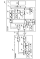
図1は、本実施例に係る表示システムの一例を示す図である。本実施例に係る表示システムは、互いに接続可能な端末装置100と表示装置200を有する。端末装置100は、1本のThunderbolt(登録商標)ケーブル300(TBケーブル)を用いて、表示装置200に接続されている。
端末装置100は、PC(Personal Computer)、タブレットコンピュータといった情報機器である。端末装置100は、DP(DisplayPort)の信号の出力と、PCIe(Peripheral Component Interconnect Express)の信号の入出力とに対応している。
表示装置200は、内部にGPU(Graphics Processing Unit;第2画像処理プロセッサ)を有する。表示装置200は、DPの信号(DP信号)の入力と、PCIeの信号(PCIe信号)の入出力とに対応している。
<Example 1>
FIG. 1 is a diagram illustrating an example of a display system according to the present embodiment. The display system according to the present embodiment includes a
The
The
本実施例では、端末装置100から表示装置200へDP信号が伝送される。また、端末装置100と表示装置200の間でPCIe信号が伝送される。なお、図1では、わかり易くするために、端末装置100から表示装置200へのDP信号の伝送路と、端末装置100と表示装置200の間のPCIe信号の伝送路とを分けて図示している。しかし、端末装置100から表示装置200へのDP信号の伝送と、端末装置100と表示装置200の間のPCIe信号の伝送とは、1本のTBケーブル300を用いて行われる。即ち、1本のTBケーブル300を用いて端末装置100を表示装置200に接続することにより、端末装置100から表示装置200へのDP信号の伝送と、端末装置100と表示装置200の間のPCIe信号の伝送との両方が可能となる。
In this embodiment, a DP signal is transmitted from the
端末装置100について説明する。
The
第1制御部101は、端末装置100の各機能部を制御するCPUである。また、第1制御部101は、表示装置200のGPU(後述する第2画像処理部204)を制御する。
第1メモリ部102は、第1制御部101が使用するワークメモリである。
第1信号変換部103は、第1制御部101からの信号をPCIe信号に変換する。また、第1信号変換部103は、入力されたPCIe信号を第1制御部101で処理可能な信号に変換し、変換後の信号を第1制御部101に出力する。
The first control unit 101 is a CPU that controls each functional unit of the
The
The first
第1画像処理部104は、画像データから画像信号を生成する生成処理を行うGPU(第1画像処理プロセッサ)である。第1画像処理部104は、第1制御部101からの指示に応じて生成処理を行う。具体的には、第1制御部101は、画像データとコマンドを含む信号を、第1信号変換部103を介して第1画像処理部104に出力する。第1画像処理部104は、コマンドの入力に応じて、入力された画像データから画像信号を生成する。
第1GPUメモリ部105は、第1画像処理部104が使用するグラフィックスメモリである。
The first
The first
画像出力部106は、第1画像処理部104で生成された画像信号をDP信号に変換して、当該DP信号を端末装置100の外部に出力する。本実施例では、端末装置100から出力されたDP信号は、TBケーブル300を介して表示装置200に入力される。
第1信号入出力部107は、端末装置100の内部から外部へのPCIe信号の出力、端末装置100の外部から内部へのPCIe信号の入力を行う。第1制御部101は、第1信号入出力部107を用いてコマンドを外部機器に出力することにより、外部機器を制御することができる。本実施例では、第1制御部101は、第1信号入出力部107を用いて、第2画像処理部204に生成処理を行わせるための信号(画像データとコマンド)を表示装置200に出力する。それにより、第2画像処理部204に生成処理を行わせることができる。なお、第2画像処理部204に生成処理を行わせるための信号は、TBケーブル300を介して表示装置200に入力される。
The
The first signal input /
表示装置200について説明する。
The
第2制御部201は、表示装置200の各機能部を制御するCPUである。
第2メモリ部202は、第2制御部201が使用するワークメモリである。
第2信号変換部203は、第2制御部201からの信号をPCIe信号に変換する。
また、第2信号変換部203は、入力されたPCIe信号を第2信号変換部203で処理可能な信号に変換し、変換後の信号を第2制御部201に出力する。
The
The
The second
The second
第2画像処理部204は、画像データから画像信号を生成する生成処理を行うGPU(第2画像処理プロセッサ)である。第2画像処理部204は、第2制御部201からの指示に応じて生成処理を行う。具体的には、第2制御部201は、画像データとコマンドを含む信号を、第2信号変換部203を介して第2画像処理部204に出力する。第2画像処理部104は、コマンドの入力に応じて、入力された画像データから画像信号を生成する。
また、第2画像処理部204は、外部機器からの指示に応じて生成処理を行うこともできる。本実施例では、第2画像処理部204は、端末装置100(具体的には第1制御部101)からの指示に応じて生成処理を行う。具体的には、第1制御部101から出力された画像データとコマンドが第2画像処理部204に入力されると、第2画像処理部204は、当該画像データから画像信号を生成する。
第2GPUメモリ部205は、第2画像処理部204が使用するグラフィックスメモリである。また、第2GPUメモリ部205は、複数フレーム分の画像信号を保持するフレームメモリとしても機能する。
The second
The second
The second
画像入力部206は、表示装置200の外部から入力されたDP信号を画像信号に変換する。上述したように、本実施例では、端末装置100(画像出力部106)から出力さ
れたDP信号が、TBケーブル300を介して表示装置200(画像入力部206)に入力される。
第2信号入出力部207は、表示装置200の内部から外部へのPCIe信号の出力、表示装置200の外部から内部へのPCIe信号の入力を行う。第2制御部201は、第2信号入出力部207を用いて外部機器からの要求に対して応答することができる。本実施例では、第2制御部201は、第2信号入出力部207を用いて、端末装置100(第1制御部101)からの要求に対する応答を表す応答信号を端末装置100に出力する。なお、応答信号は、TBケーブル300を介して端末装置100に入力される。
The
The second signal input /
出力選択部208は、画像表示部209で表示する画像を、画像入力部206に入力されたDP信号を変換して得られた画像信号(第1画像信号)と、第2画像処理部204で生成された画像信号(第2画像信号)との間で切り替える。具体的には、出力選択部208は、第2制御部201からの指示に応じて、第1画像信号または第2画像信号を、表示する画像信号として選択する。そして、出力選択部208は、選択した画像信号を出力する。画像入力部206に入力されたDP信号を変換して得られた第1画像信号は、第1画像処理部104で生成された画像信号である。
画像表示部209は、出力選択部208で選択された画像信号に基づく画像を表示する。
The
The
同期信号検出部210は、第1画像信号の同期信号と第2画像信号の同期信号を検出し、検出したそれらの同期信号を第2制御部201に通知する。第2制御部201は、第1画像信号と第2画像信号の同期をとる同期処理を行う。この処理の詳細は後述する。また、第1画像信号と第2画像信号の同期がとれた後に、第2制御部201は、同期信号検出部210から通知された垂直同期信号(第1画像信号と第2画像信号の垂直同期信号)のタイミングで出力選択部208の出力を切り替える。これにより、表示装置200(画像表示部209)の表示を垂直同期信号に同期して切り替えることができる。
なお、同期処理は第2制御部201以外の機能部により行われてもよい。例えば、同期処理は、不図示の同期部(表示装置200が有する同期部)により行われてもよい。
The synchronization
Note that the synchronization process may be performed by a functional unit other than the
制御選択部211は、第2制御部201からの指示に応じて、PCIe信号の伝送路を切り替える。本実施例では、制御選択部211は、3つの伝送路の間で切り替えを行う。1つ目の伝送路は、第2画像処理部204と第2信号変換部203の間の伝送路である。第2画像処理部204と第2信号変換部203を接続することにより、第2画像処理部204において、第2制御部201からの指示に応じた生成処理が実行可能となる。2つ目の伝送路は、第2画像処理部204と第2信号入出力部207の間の伝送路である。第2画像処理部204と第2信号入出力部207を接続することにより、端末装置100から表示装置200に入力されたPCIe信号を第2画像処理部204に伝送することができるようになる。その結果、第2画像処理部204において、第1制御部101からの指示に応じた生成処理が実行可能となる。3つ目の伝送路は、第2信号入出力部207と第2信号変換部203の間の伝送路である。第2信号入出力部207と第2信号変換部203を接続することにより、端末装置100から表示装置200に入力されたPCIe信号を、第2制御部201で処理可能な信号に変換し、変換後の信号を第2制御部201に伝送することができるようになる。また、第2制御部201から出力された信号をPCIe信号に変換し、当該PCIe信号を表示装置200から端末装置100に出力することができるようになる。その結果、第2制御部201と第1制御部101の間での通信が可能となる。
The
キャプチャ部212は、第1画像信号を取得し、第2画像処理部204へ出力する。第2画像処理部204は、キャプチャ部212から出力された第1画像信号に基づいて種々の処理を行うことができる。例えば、第2画像処理部204は、第1画像信号のフレーム
番号(動画内の時間位置)に基づいて、生成する第2画像信号のフレームを調整することができる。また、第2画像処理部204は、第2画像信号に第1画像信号を用いた画像処理を施すことができる。
The
本実施例では、第1制御部101は、端末装置100が表示装置200に接続された際に、第1画像処理部104と第2画像処理部204のどちらを用いるかを判断する。ユーザのニーズを考えると、第1画像処理部104と第2画像処理部204のうち、より性能が高い方の画像処理部で生成された画像信号に基づく画像を表示することが好ましい。そこで、本実施例では、第1制御部101は、第1画像処理部104と第2画像処理部204のうち、より性能が高い方の画像処理部を用いると判断する。
しかし、第1制御部101が第2画像処理部204を制御する(第1制御部101が第2画像処理部204に生成処理の実行の指示を行う)ためには、第2画像処理部204のドライバ(ドライバソフトウェア)のインストールや起動といった前処理が必要である。そのため、第2画像処理部204を表示に用いる場合に、画像が表示されるまでの時間が長くなってしまうという課題がある。
そこで、本実施例では、第1制御部101は、第2画像処理部204を用いると判断した場合に、上記前処理を行うと共に、第1画像処理部104に表示用画像データから画像信号を生成する指示を行う。第1制御部101は、上記前処理が完了した後に、第2画像処理部204に上記表示用画像データから画像信号を生成する指示を行う。そして、出力選択部208は、少なくとも第2画像処理部204で画像信号が生成されるまで、画像表示部209に、第1画像処理部104で生成された画像信号を表示させる。具体的には、少なくとも第2画像処理部204で画像信号が生成されるまで第1画像処理部104で生成された画像信号が選択されるように、第1制御部101が出力選択部208を制御する。それにより、短い時間で画像を表示することができる。また、出力選択部208は、第2画像処理部204で画像信号が生成された後に、画像表示部209で表示する画像を、第1画像処理部104で生成された画像信号に基づく画像から、第2画像処理部204で生成された画像信号に基づく画像に切り替える。
In the present embodiment, the first control unit 101 determines whether to use the first
However, in order for the first control unit 101 to control the second image processing unit 204 (the first control unit 101 instructs the second
Therefore, in the present embodiment, when the first control unit 101 determines that the second
なお、第2画像処理部204の性能が第1画像処理部104の性能より高いか否かの判定は、例えば、第2画像処理部204の性能を表す情報と、第1画像処理部104の性能を表す情報とを比較することにより行うことができる。第2画像処理部204の性能を表す情報は、端末装置100内に予め記憶されていてもよいし、ユーザによって入力されてもよい。第1画像処理部104の性能を表す情報は、表示装置200内に予め記憶されていてもよいし、ユーザによって入力されてもよい。
なお、使用する画像処理部は、表示用画像データの種類に基づいて決定されてもよい。例えば、表示用画像データが静止画データである場合に第1画像処理部104を用いると判断され、表示用画像データが動画データである場合に第2画像処理部204を用いると判断されてもよい。医用画像データである場合に第1画像処理部104を用いると判断され、表示用画像データがイラストデータである場合に第2画像処理部204を用いると判断されてもよい。また、ユーザによって選択された画像処理部が、使用する画像処理部として判断されてもよい。
Note that the determination of whether or not the performance of the second
The image processing unit to be used may be determined based on the type of display image data. For example, it is determined that the first
本実施例に係る表示システムの動作の一例について説明する。
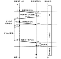
図2は、第2画像処理部204のドライバがインストールされておらず、DP信号を出力している状態の端末装置100が、表示装置200に接続されたときの、表示システム(端末装置100と表示装置200)の動作の一例を示すタイミングチャートである。図2には、画像表示部209の表示状態の変化が図示されている。表示状態「OFF」は、表示が行われていない状態(または外部機器から表示装置200へのDP信号の入力が無い状態)を意味する。表示状態「DP表示」は、端末装置100から出力されたDP信号(即ち、第1画像信号)に基づく画像が表示されている状態を意味する。表示状態「PC
Ie表示」は、制御部101からの指示に応じて第2画像処理部204で生成された第2画像信号に基づく画像が表示されている状態を意味する。
An example of the operation of the display system according to the present embodiment will be described.
2 shows a display system (with the
“Ie display” means a state in which an image based on the second image signal generated by the second
時刻t0では、端末装置100が表示装置200に接続されていないため、表示状態は「OFF」となっている。
時刻t1で、端末装置100がTBケーブル300を用いて表示装置200に接続される。このとき、端末装置100(画像出力部106)からはDP信号が出力されている。このDP信号は、TBケーブル300を介して表示装置200(画像入力部206)に入力され、画像信号(第1画像信号)に変換される。
時刻t2で、表示状態が「DP表示」に切り替わる。具体的には、時刻t2で、同期信号検出部210は、DP信号を変換して得られた第1画像信号の同期信号を検出し、第2制御部201へ通知する。そして、第2制御部201は、第1画像信号の垂直同期信号に同期して、第1画像信号を選択するように出力選択部208を制御する。それにより、画像表示部209では、DP信号を変換して得られた第1画像信号に基づく画像が表示される。
時刻t3で、第2制御部201は、制御選択部211を介して第2信号入出力部207と接続し、TBケーブル300を介して端末装置100の第1制御部101との接続を試みる。
At time t0, since the
At time t1, the
At time t2, the display state is switched to “DP display”. Specifically, at time t2, the synchronization
At time t <b> 3, the
時刻t4で、第2制御部201と第1制御部101のPCIe接続が確立し、表示装置200が有するGPU(第2画像処理部204)の情報が第1制御部101へと通知される。第1制御部101は、上記GPUの情報を基に、第2画像処理部204を直接制御するためのドライバをインストールするか否かを検討する。
ここで、ドライバをインストールするか否かの検討方法の一例を挙げる。
VGA(Video Graphics Array)サイズの単純なグラフィック(矩形画像など)を生成する処理を予め第1画像処理部104で実行しておく。そして、1秒間に生成可能なグラフィックの数をカウントして第1メモリ部に保存しておく。第1制御部101は、上記処理(グラフィックの繰り返し生成)と同じ処理を第2画像処理部204に実行させるための命令(PCIe信号)を、TBケーブル300を介して第2制御部201に伝送する。そして、第2制御部201が、上記命令を用いて、上記処理と同じ処理を第2画像処理部204に実行させる。第2画像処理部204は、1秒間に生成できたグラフィックの数をカウントして、第2制御部201に通知する。第2制御部201が、第2画像処理部204から通知されたカウント数(グラフィックの数)を第1制御部101に通知する。第1制御部101は、表示装置200(第2画像処理部204)と端末装置100(第1画像処理部104)のカウント数を比較する。表示装置200が1秒間に端末装置100よりも多くのグラフィックを生成できるならば、第1制御部101は、第2画像処理部204の性能が第1画像処理部104の性能よりも高いと判断する。そして、第1制御部101は、第2画像処理部204のドライバを端末装置100にインストールすると判定する。
なお、第2画像処理部204の性能が第1画像処理部104の性能よりも高いか否か(ドライバをインストールするか否か)の判定方法は、上記方法に限らない。例えば、GPUの性能を判断するベンチマークソフトを予め各々の装置で実行し、ソフトの実行結果(スコア)がデータベース化されていてもよい。この場合、時刻t4の時点で第1制御部101に通知されたGPU(第2画像処理部204)の型番に対応するスコアと、第1画像処理部104の型番に対応するスコアとを上記データベースから参照すればよい。そして、第2画像処理部204のスコアと、第1画像処理部104のスコアとに基づいて、ドライバをインストールするか否かが検討されてもよい。性能が高いほどスコアが高いならば、第2画像処理部204のスコアが第1画像処理部104のスコアより高い場合に、ドライバをインストールすると判定すればよい。また、上記データベースは必ずしも端末装置100が保持する必要はない。端末装置100がインターネット接続できるのであれば、
上記データベースはネットワークから取得されてもよい。
At time t4, the PCIe connection between the
Here, an example of a method for examining whether or not to install a driver is given.
A process for generating a simple graphic (rectangular image or the like) having a VGA (Video Graphics Array) size is executed in advance by the first
Note that a method for determining whether or not the performance of the second
The database may be obtained from a network.
第2画像処理部204のドライバを端末装置100にインストールすると判定されると、時刻t5で、第1制御部101は、TBケーブル300を介して、第2制御部201に、第2画像処理部204のドライバを要求するPCIe信号を伝送する。
時刻t6で、第2制御部201は、端末装置100(第1制御部101)からの要求(ドライバの送信の要求)を受け付ける。
時刻t7で、第2制御部201は、第1制御部101へのドライバの送信を開始する。ドライバ(PCIe信号)は、TBケーブル300を介して第2制御部201から第1制御部101へ送信される。なお、ここでは、表示装置200が第2画像処理部204のドライバを保持していることを前提としている。しかし、表示装置200や端末装置100がインターネットに接続できるのであれば、ネットワークからドライバを取得することが可能となるため、表示装置200は必ずしもドライバを保持する必要はない。また、端末装置100がインターネットに接続できる場合は、端末装置100は、表示装置200を介さずに、直接ネットワークからドライバを取得してもよい。
When it is determined that the driver of the second
At time t6, the
At time t7, the
時刻t8で、第1制御部101によるドライバ(インストールするドライバ;第2画像処理部204のドライバ)の取得が完了する。そして、第1制御部101は、ドライバのインストールを開始する。
時刻t9で、第2画像処理部204のドライバのインストールが完了し、第1制御部101は、当該ドライバの起動を行う。
時刻t10で、第2制御部201は、制御選択部211を制御して、第2信号入出力部207と第2画像処理部204を接続する。それにより、端末装置100の第1制御部101から第2画像処理部204を直接制御できるようになる。第1制御部101は、ドライバの起動が完了し、第2画像処理部204との接続が確立すると、TBケーブル300を介して、直接第2画像処理部204に対して生成処理の実行指示(具体的には画像データとコマンド)を送り始める。ここで、画像データは、DP信号の生成のために使用された画像データと同じ画像データ(表示用画像データ)である。
At time t8, acquisition of the driver (driver to be installed; driver of the second image processing unit 204) by the first control unit 101 is completed. Then, the first control unit 101 starts driver installation.
At time t9, the driver installation of the second
At time t <b> 10, the
時刻t11で、第2画像処理部204による生成処理が開始する。また、このタイミングで、第2制御部201が同期処理を行う。同期処理は、「生成フレームの調整」と「Vsyncの同期」を含む。「生成フレームの調整」は、第2画像処理部で生成される画像信号(第2画像信号)のフレーム(動画像内の時間位置)と、第1画像処理部で生成される画像信号(DP信号から生成される画像信号;第1画像信号)のフレームとを一致させる処理である。「Vsyncの同期」は、第2画像信号の垂直同期信号と第1画像信号の垂直同期信号との同期をとる処理である。具体的には、「生成フレームの調整」では、第2画像信号と、DP信号から生成された画像信号(第1画像信号)の比較が行われる。そして、比較結果に基づき、出力選択部208に同じフレームの第1画像信号と第2画像信号が入力されるように、それぞれのGPUが生成するフレームが調整される。「Vsyncの同期」では、同期信号検出部210が、第1画像信号と第2画像信号の同期信号を検知して、第2制御部201へと通知する。第2制御部201は、通知された同期信号に基づいて、それらの画像信号の垂直同期信号の同期をとる処理を行う。同期処理の詳細な説明は、後述する。
At time t11, generation processing by the second
時刻t12で、同期信号検出部210が、第2画像処理部204の出力する垂直同期信号を第2制御部201に通知する。この垂直同期信号のタイミングで表示が第1画像信号に基づく画像から第2画像信号に基づく画像に切り替わるように、第2制御部201は、出力選択部208を制御する。時刻t12以降、画像表示部209には、第2画像処理部204において生成された第2画像信号に基づく画像が表示される。
At time t12, the synchronization
なお、上述した動作は、第1制御部101が第2画像処理部204を直接制御する場合(端末装置100にドライバをインストールすると判定された場合)の例である。第1制御部101が第2画像処理部204を直接制御しない場合(例えば、端末装置100にドライバをインストールしないと判定された場合)には、時刻t4より後の上記処理(時刻t5〜t12の処理)は行われず、表示状態「DP表示」が維持される。
なお、表示状態が「DP表示」から「PCIe表示」に切り替わった後は、第1画像処理部104による生成処理は、実行され続けてもよいし、停止されてもよい。
The above-described operation is an example when the first control unit 101 directly controls the second image processing unit 204 (when it is determined to install a driver in the terminal device 100). When the first control unit 101 does not directly control the second image processing unit 204 (for example, when it is determined not to install a driver in the terminal device 100), the above processing after time t4 (from time t5 to t12). Processing) is not performed, and the display state “DP display” is maintained.
Note that after the display state is switched from “DP display” to “PCIe display”, the generation processing by the first
図3は、第2画像処理部204のドライバがインストールされており、DP信号を出力している状態の端末装置100が、表示装置200に接続されたときの、表示システムの動作の一例を示すタイミングチャートである。なお、以下の説明における各時刻は、特にことわりが無い限り、図3に記載の時刻を意味する。
時刻t0〜t3の処理は、それぞれ図2の時刻t0〜t3の処理と同じであるため、それらの説明は省略する。
時刻t4で、表示装置200(第2制御部201)と端末装置100(第1制御部101)とのPCIe接続が確立し、表示装置200が有するGPU(第2画像処理部204)の情報が第1制御部101へと通知される。第1制御部101は、上記GPUの情報を基に、第2画像処理部204を直接制御するためのドライバが既にインストールされていると判断する。そして、第1制御部101は、上記GPUの情報を基に、ドライバ(第2画像処理部204のドライバ)を起動するか否かの検討を行う。なお、ドライバを起動するか否かの判定方法(検討方法)は、図2を用いて説明した判定方法(ドライバをインストールするか否かの判定方法)と同じであるため、その説明は省略する。
第2画像処理部204のドライバを起動すると判定されると、時刻t5で、第1制御部101は、ドライバ(第2画像処理部204のドライバ)を起動する。
時刻t6、時刻t7、時刻t8の処理は、それぞれ、図2の時刻t10、時刻t11、時刻t12の処理と同じであるため、それらの説明は省略する。
FIG. 3 shows an example of the operation of the display system when the
Since the processes at times t0 to t3 are the same as the processes at times t0 to t3 in FIG. 2, their descriptions are omitted.
At time t4, the PCIe connection between the display device 200 (second control unit 201) and the terminal device 100 (first control unit 101) is established, and information on the GPU (second image processing unit 204) included in the
If it is determined to activate the driver of the second
The processes at time t6, time t7, and time t8 are the same as the processes at time t10, time t11, and time t12 in FIG.
なお、上述した動作は、第1制御部101が第2画像処理部204を直接制御する場合(第2画像処理部204のドライバを起動すると判定された場合)の例である。第1制御部101が第2画像処理部204を直接制御しない場合(例えば、第2画像処理部204のドライバを起動しないと判定された場合)には、時刻t4より後の上記処理(時刻t5〜t8の処理)は行われず、表示状態「DP表示」が維持される。 The above-described operation is an example when the first control unit 101 directly controls the second image processing unit 204 (when it is determined to activate the driver of the second image processing unit 204). When the first control unit 101 does not directly control the second image processing unit 204 (for example, when it is determined not to activate the driver of the second image processing unit 204), the above processing after time t4 (time t5) The process of -t8) is not performed, and the display state “DP display” is maintained.
図4は、画像処理部204のドライバがインストールされておらず、DP信号を出力していない状態の端末装置100が、表示装置200に接続されたときの、表示システムの動作の一例を示すタイミングチャートである。なお、以下の説明における各時刻は、特にことわりが無い限り、図4に記載の時刻を意味する。
FIG. 4 is a timing diagram illustrating an example of the operation of the display system when the
時刻t1で、端末装置100がTBケーブル300を用いて表示装置200に接続される。そして、第1制御部101が、第1信号入出力部107とTBケーブル300を介して表示装置200の第2制御部201との接続(PCIe接続)を試みる。
時刻t2で、第2信号入出力部207が外部からのPCIe接続要求(PCIe信号)を検知し、当該要求を第2制御部201に通知する。第2制御部201は、当該通知に応じて、第2信号入出力部207と第2信号変換部203が接続されるように、制御選択部211を制御する。これにより、第2制御部201と第1制御部101のPCIe接続が確立する。
時刻t3で、第2制御部201は、TBケーブル300を介して、DP信号の出力を要求するPCIe信号を端末装置100(第1制御部101)へ伝送する。また、第2制御部201は、TBケーブル300を介して、表示装置200が有するGPU(第2画像処理部204)の情報であるPCIe信号を端末装置100(第1制御部101)へ伝送す
る。
At time t1, the
At time t2, the second signal input /
At time t3, the
時刻t4で、第1制御部101は、表示装置200(第2制御部201)からのDP出力要求(DP信号の出力の要求)を受け付ける。第1制御部101は、DP出力要求に応じて、第1画像処理部104に生成処理の実行指示(表示用画像データとコマンド)を送る。それにより、第1画像処理部104で表示用画像データから第1画像信号を生成する処理が行われる。また、時刻t4で、第1制御部101に、第2画像処理部204の情報が通知される。そして、第1制御部101は、上記第2画像処理部204の情報を基に、第2画像処理部204を直接制御するためのドライバをインストールするか否かを検討する。ドライバをインストールするか否かの判定方法(検討方法)は、図2を用いて説明した判定方法と同じであるため、その説明は省略する。
At time t4, the first control unit 101 receives a DP output request (DP signal output request) from the display device 200 (second control unit 201). In response to the DP output request, the first control unit 101 sends a generation process execution instruction (display image data and command) to the first
時刻t101で、画像出力部106からDP信号(表示用画像データから生成された第1画像信号を変換して得られたDP信号)が出力される。そして、このDP信号は、TBケーブル300を介して表示装置200(画像入力部206)に入力され、画像信号(第1画像信号)に変換される。
時刻t102で、同期信号検出部210は、DP信号を変換して得られた上記第1画像信号の同期信号を検知して第2制御部201へ通知する。第2制御部201は上記第1画像信号の垂直同期信号のタイミングで当該第1画像信号に基づく画像の表示が開始されるように、出力選択部208を制御する。時刻t102以降、画像表示部209には、第1画像処理部104において生成された第1画像信号に基づく画像が表示される。なお、時刻t102以前では、画像表示部209の表示状態は「OFF」である。
第2画像処理部204のドライバを端末装置100にインストールすると判定されると、時刻t5から時刻t12の処理が行われる。時刻t5から時刻t12の処理は、図2の時刻t5〜t12の処理と同じであるため、それらの説明は省略する。
At time t101, the
At time t102, the synchronization
When it is determined that the driver of the second
なお、上述した動作は、第1制御部101が第2画像処理部204を直接制御する場合(端末装置100にドライバをインストールすると判定された場合)の例である。第1制御部101が第2画像処理部204を直接制御しない場合(例えば、端末装置100にドライバをインストールしないと判定された場合)には、時刻t5〜t12の処理は行われず、時刻t102から表示状態「DP表示」が維持される。 The above-described operation is an example when the first control unit 101 directly controls the second image processing unit 204 (when it is determined to install a driver in the terminal device 100). When the first control unit 101 does not directly control the second image processing unit 204 (for example, when it is determined not to install a driver in the terminal device 100), the processing from time t5 to t12 is not performed, and from time t102 The display state “DP display” is maintained.
図5は、第2画像処理部204のドライバがインストールされており、DP信号を出力していない状態の端末装置100が、表示装置200に接続されたときの、表示システムの動作の一例を示すタイミングチャートである。なお、以下の説明における各時刻は、特にことわりが無い限り、図5に記載の時刻を意味する。
時刻t0〜t3の処理は、図4の時刻t0〜t3の処理と同じであるため、それらの説明は省略する。
時刻t4で、第1制御部101は、表示装置200(第2制御部201)からのDP出力要求(DP信号の出力の要求)を受け付ける。第1制御部101は、DP出力要求に応じて、第1画像処理部104に生成処理の実行指示(表示用画像データとコマンド)を送る。それにより、第1画像処理部104で表示用画像データから第1画像信号を生成する処理が行われる。また、時刻t4で、第1制御部101に、第2画像処理部204の情報が通知される。第1制御部101は、上記第2画像処理部204の情報を基に、第2画像処理部204を直接制御するためのドライバが既にインストールされていると判断する。そして、第1制御部101は、上記第2画像処理部204の情報を基に、第2画像処理部204のドライバを起動するか否かを検討する。ドライバを起動するか否かの判定方法(検討方法)は、図2を用いて説明した判定方法(ドライバをインストールするか否かの判定方法)と同じであるため、その説明は省略する。
時刻t101、時刻t102の処理は、それぞれ、図4の時刻t101、時刻t102
の処理と同じであるため、それらの説明は省略する。
第2画像処理部204のドライバを起動すると判定されると、時刻t5で、第1制御部はドライバ(第2画像処理部204のドライバ)を起動する。
そして、時刻t6、時刻t7、時刻t8の処理は、それぞれ、図4の時刻t10、時刻t11、時刻t12の処理と同じであるため、それらの説明は省略する。
FIG. 5 shows an example of the operation of the display system when the
The processing at times t0 to t3 is the same as the processing at times t0 to t3 in FIG.
At time t4, the first control unit 101 receives a DP output request (DP signal output request) from the display device 200 (second control unit 201). In response to the DP output request, the first control unit 101 sends a generation process execution instruction (display image data and command) to the first
The processes at time t101 and time t102 are respectively performed at time t101 and time t102 in FIG.
Since the processing is the same as those in FIG.
If it is determined that the driver of the second
The processes at time t6, time t7, and time t8 are the same as the processes at time t10, time t11, and time t12 in FIG.
なお、上述した動作は、第1制御部101が第2画像処理部204を直接制御する場合(第2画像処理部204のドライバを起動と判定された場合)の例である。第1制御部101が第2画像処理部204を直接制御しない場合(例えば、第2画像処理部204のドライバを起動しないと判定された場合)には、時刻t5〜t8の処理は行われず、時刻t102から表示状態「DP表示」が維持される。
The above-described operation is an example when the first control unit 101 directly controls the second image processing unit 204 (when it is determined that the driver of the second
図6は、端末装置100を表示装置200に接続したときの表示システムの動作の一例を示すフローチャートである。
まず、S101で、TBケーブル300を用いて、端末装置100が表示装置200に接続される。図2の例では、時刻t1にS101の処理が行われる。
次に、S102で、端末装置100がDP信号を出力し、表示装置200が入力されたDP信号に基づく画像を画像表示部209に表示する。図2の例では、時刻t2にS102の処理による画像の表示が開始される。
そして、S103で、端末装置100が、表示装置200が有するGPU(第2画像処理部204)の性能を見積もる。図2の例では、時刻t4にS103の処理が開始される。
FIG. 6 is a flowchart illustrating an example of the operation of the display system when the
First, in S <b> 101, the
Next, in S102, the
In step S103, the
次に、S104で、端末装置100が、表示装置200が有するGPU(第2画像処理部204)を直接制御するか否かを決める。本実施例では、第2画像処理部204の性能よりも第1画像処理部104の性能が高い場合に、端末装置100は、第2画像処理部204を(直接)制御しないと判断する。そして、本処理フローが終了される(表示状態「DP表示」が維持される)。第1画像処理部104の性能よりも第2画像処理部204の性能が高い場合には、S105に処理が進められる。図2の例では、時刻t5にS104の処理が完了し、S105に処理が進められる。
Next, in S104, the
S105で、第1制御部101が、端末装置100に第2画像処理部204のドライバがインストールされているか否かを判断する。端末装置100に第2画像処理部204のドライバがインストールされている場合には、S106に処理が進められる。端末装置100に第2画像処理部204のドライバがインストールされていない場合には、S107に処理が進められる。図2の例では、時刻t5にS105の処理が開始され、S106に処理が進められる。図3の例では、時刻t5にS105の処理が開始され、S107に処理が進められる。
In step S <b> 105, the first control unit 101 determines whether the driver for the second
S106で、第1制御部101が、端末装置100に第2画像処理部204のドライバをインストールする処理を行う。そして、S107に処理が進められる。図2の例では、時刻t5から時刻t9までの期間にS106の処理が行われる。
S107で、第1制御部101が、端末装置100にインストールされたドライバ(第2画像処理部204のドライバ)を起動する処理を行う。図2の例では、時刻t9から時刻t10までの期間にS107の処理が行われる。
In step S <b> 106, the first control unit 101 performs processing for installing the driver of the second
In step S <b> 107, the first control unit 101 performs processing for starting a driver installed in the terminal device 100 (a driver of the second image processing unit 204). In the example of FIG. 2, the process of S107 is performed during a period from time t9 to time t10.
S107の次に、S108で、第1制御部101から第2画像処理部204へ、生成処理の実行指示(画像データとコマンド)が伝送される。具体的には、生成処理の実行指示を表すPCIe信号が、TBケーブル300を介して、第1制御部101から第2画像処理部204へ伝送される。図2の例では、時刻t10にS108の処理が開始される。
そして、S109で、第2画像処理部204が、第1制御部101からの指示に応じて生成処理を開始する。図2の例では、時刻t11にS109の処理が開始される。
次に、S110で、第2制御部201が同期処理を行う。その後、第2制御部201が出力選択部208を制御することにより、第2画像処理部204で生成された第2画像信号が画像表示部209に伝送される。それにより、第1画像信号に基づく画像から第2画像信号に基づく画像へ表示が切り替えられる。図2の例では、時刻t11から時刻t12までの期間において、S110の処理が行われる。
Following S107, the generation control execution instruction (image data and command) is transmitted from the first control unit 101 to the second
In step S <b> 109, the second
Next, in S110, the
S110の同期処理の詳細について、図7のフローチャートを用いて説明する。上述したように、同期処理は、「生成フレームの調整」と「Vsyncの同期」を含む。また、S110では、「Vsyncに同期した出力切り替え」も行われる。 Details of the synchronization processing in S110 will be described with reference to the flowchart of FIG. As described above, the synchronization processing includes “adjustment of generated frames” and “synchronization of Vsync”. In S110, “output switching synchronized with Vsync” is also performed.
(1)「生成フレームの調整」
「生成フレームの調整」は、出力選択部208に同じフレームの第2画像信号と第1画像信号を入力するための調整処理である。第2画像信号のフレームと第1画像信号のフレームとを合わせることにより、出力選択部208の出力を切り替えたときに、表示される画像のフレームがスキップすることを防ぐことができる。
図8は「生成フレームの調整」を説明するための説明図である。
図7,8を用いて、「生成フレームの調整」の一例を説明する。
(1) “Adjustment of generated frames”
“Adjustment of generated frame” is an adjustment process for inputting the second image signal and the first image signal of the same frame to the
FIG. 8 is an explanatory diagram for explaining “adjustment of generated frames”.
An example of “adjustment of generated frame” will be described with reference to FIGS.
まず、S111で、第2画像処理部204は、第1制御部101からの指示に応じて生成したNフレーム分の第2画像信号を第2GPUメモリ部205に格納する。図8は、N=4の例を示している。
次に、S112で、キャプチャ部212が、第1画像信号を取得し、第2画像処理部204へ出力する。第2画像処理部204は、キャプチャされた第1画像信号を第2GPUメモリ部205に格納する。図8は、キャプチャ(取得)した第1画像信号が互いに異なる2つの場合(Case1とCase2)を示している。
そして、S113で、第2画像処理部204は、第1制御部101からの指示に応じて生成したMフレーム分の第2画像信号を第2GPUメモリ部205に格納する。ここで、第2GPUメモリ部205には、N+Mフレーム分の第2画像信号およびキャプチャした第1画像信号が格納されている。図8は、M=3の例を示している。
First, in step S <b> 111, the second
Next, in S <b> 112, the
In step S <b> 113, the second
次に、S114で、第2画像処理部204は、キャプチャされた第1画像信号と、N+Mフレームの第2画像信号との相関を求める。そして、第2画像処理部204は、上記N+Mフレームの中から、キャプチャされた第1画像信号と最も相関が高いフレームを選択する。本実施例では、上記N+Mフレームに対して、順番に1〜N+Mの番号(フレーム番号)が割り当てられる。そして、キャプチャされた第1画像信号と最も相関が高いフレームの番号Aが決定される。図8の例において、Case1の場合にはA=3となり、Case2の場合にはA=6となる。
2つのフレーム(2つの画像)の相関の度合いは、例えば、2画像間の画素毎の差の絶対値の総和から判断することができる。具体的には、上記総和が小さいほど相関が高いと判断することができる。そのため、キャプチャした第1画像信号の座標(x,y)における画素値をP0(x,y)、第2画像信号の座標(x,y)における画素値をP(x,y)とすると、以下の式1で得られる値が最も小さい第2画像信号のフレーム番号がAとなる。

なお、第1画像信号と第2画像信号の解像度(画像サイズ)が異なる場合には、第1画像信号と第2画像信号の解像度を互いに等しくするスケーリング処理(拡大処理または縮小処理)を行うことにより、上記計算が可能となる。なお、スケーリング処理は、第1画像信号に施されてもよいし、第2画像信号に施されてもよい。
Next, in S114, the second
The degree of correlation between two frames (two images) can be determined, for example, from the sum of the absolute values of differences for each pixel between the two images. Specifically, it can be determined that the smaller the sum is, the higher the correlation is. Therefore, if the pixel value at the coordinates (x, y) of the captured first image signal is P0 (x, y) and the pixel value at the coordinates (x, y) of the second image signal is P (x, y), The frame number of the second image signal having the smallest value obtained by the following
When the resolution (image size) of the first image signal and the second image signal is different, a scaling process (enlargement process or reduction process) is performed to make the resolutions of the first image signal and the second image signal equal to each other. Thus, the above calculation is possible. Note that the scaling process may be performed on the first image signal or the second image signal.
S114の次に、S115で、第2画像処理部204は、AがN以下か否かを判定する。AがN以下である場合、S116に処理が進められる。AがNより大きい場合、S117に処理が進められる。図8の例において、Case1の場合には、AがN以下と判定され、S116に処理が進められる。Case2の場合には、AがNより大きいと判定され、S117に処理が進められる。
S116では、第2画像処理部204の出力がN−Aフレーム分遅延される。第2画像処理部204の出力は、第2GPUメモリ部205を用いて遅延される。図8の例において、Case1の場合には、A=3、N=4であるため、第2GPUメモリ部205を用いて、第2画像処理部204の出力が1フレーム分遅延される。それにより、第2画像信号のフレームが第1画像信号のフレームと一致する。
S117では、第1画像処理部104の出力がA−Nフレーム分遅延される。第1画像処理部104の出力は、第1GPUメモリ部105を用いて遅延される。図8の例において、Case2の場合には、A=6、N=4であるため、第1GPUメモリ部105を用いて、第1画像処理部104の出力が2フレーム分遅延される。それにより、第2画像信号のフレームが第1画像信号のフレームと一致する。
フレームの遅延は、例えば、AとNの差を第2制御部201が取得し、第2制御部201が第2画像処理部204を制御したり、第2制御部201が第1画像処理部104を制御するよう第1制御部101に指示を送ることにより実現される。
なお、相関は第2制御部201により求められてもよい。
Following S114, in S115, the second
In S116, the output of the second
In S117, the output of the first
As for the delay of the frame, for example, the
The correlation may be obtained by the
以上により、「生成フレームの調整」が完了する。
S116またはS117の次に、S118に処理が進められる。
Thus, the “adjustment of generated frame” is completed.
Following S116 or S117, the process proceeds to S118.
(2)「Vsyncの同期」
S118で、同期信号検出部210は、第2画像処理部204で生成された第2画像信号のVsync(垂直同期信号)を検知して、その発生時刻tgを判断する。
次に、S119で、同期信号検出部210は、画像入力部206で得られた第1画像信号のVsyncを検知して、その発生時刻tdpを判断する。発生時刻tgと発生時刻tdpは、同じフレームの第2画像信号と第1画像信号のVsyncの発生時刻である。
なお、同期信号検出部210は時刻tgおよび時刻tdpをそれぞれ独立して判断できるものとする。このため、S119の処理の後にS118の処理が行われてもよい。
(2) “Synchronization of Vsync”
In S118, the synchronization
Next, in S119, the synchronization
Note that the synchronization
そして、S120で、時刻tgおよび時刻tdpの値が第2制御部201に送られる。第2制御部201は、これらの値(時刻tgおよび時刻tdpの値)を基に、第2画像処理部204を制御して、第2画像信号と第1画像信号の同期をとる。
例えば、時刻tgと時刻tdpの差の絶対値が算出され、この絶対値が所定の閾値(メーカやユーザによって設定された閾値)より小さいか否かが判定される。そして、絶対値が所定の閾値より小さい場合には、第2画像信号と第1画像信号の同期がとれていると判断され、S124に処理が進められる。絶対値が所定の閾値以上である場合には、第2画像信号と第1画像信号の同期がとれていないと判断され、S121に処理が進められる。
なお、上記所定の閾値は、第1画像信号の垂直同期信号のフロントポーチ期間の長さよりも小さい値であることが好ましい。上記所定の閾値を第1画像信号の垂直同期信号のフロントポーチ期間の長さよりも小さい値とすることにより、画像表示部209の表示が切り替え時に乱れることを防止することができる。換言すれば、出力選択部208による第1画像信号から第2画像信号への出力信号の切り替えを、第1画像信号のブランク期間に
実施することができる。
In S120, the values of time tg and time tdp are sent to the
For example, the absolute value of the difference between the time tg and the time tdp is calculated, and it is determined whether or not this absolute value is smaller than a predetermined threshold value (threshold value set by the manufacturer or user). If the absolute value is smaller than the predetermined threshold, it is determined that the second image signal and the first image signal are synchronized, and the process proceeds to S124. If the absolute value is greater than or equal to the predetermined threshold, it is determined that the second image signal and the first image signal are not synchronized, and the process proceeds to S121.
The predetermined threshold value is preferably a value smaller than the length of the front porch period of the vertical synchronization signal of the first image signal. By setting the predetermined threshold to a value smaller than the length of the front porch period of the vertical synchronization signal of the first image signal, it is possible to prevent the display of the
S121では、第2制御部201が、時刻tgと時刻tdpの前後関係を判断する。
tg<tdpである場合(tgがtdpより前の時刻である場合)、第2画像信号の同期信号が第1画像信号よりも早まっている(第1画像信号の同期信号が第2画像信号よりも遅れている)ことが分かる。この場合は、S122に処理が進められる。S122では、第2制御部201が、第2画像信号の同期信号が時間(tdp−tg)だけ遅れるように、第2画像処理部204を制御する。
tg<tdpでない場合(tgがtdpより後の時刻である場合)、第2画像信号の同期信号が第1画像信号よりも遅れている(第1画像信号の同期信号が第2画像信号よりも早まっている)ことが分かる。この場合は、S123に処理が進められる。S123では、第2制御部201が、生成する第2画像信号のフレームが1フレーム先のフレームとなるように(生成するフレームが1つ省略されるように)、第2画像処理部204を制御する。これにより、第2画像信号の同期信号が第1画像信号の同期信号を追い越すこととなる。
S121と、それに続くS122またはS123との処理が実行された後に、S118からの処理が再度行われる。そして、S120で第1画像信号と第2画像信号の同期がとれていると判断された場合に、S124に処理が進められる。
In S121, the
When tg <tdp (when tg is a time before tdp), the synchronization signal of the second image signal is earlier than the first image signal (the synchronization signal of the first image signal is greater than the second image signal). Is also late). In this case, the process proceeds to S122. In S122, the
When tg <tdp is not satisfied (when tg is a time after tdp), the synchronization signal of the second image signal is delayed from the first image signal (the synchronization signal of the first image signal is later than the second image signal). I know that it ’s premature. In this case, the process proceeds to S123. In S123, the
After the processing of S121 and the subsequent S122 or S123 is executed, the processing from S118 is performed again. If it is determined in S120 that the first image signal and the second image signal are synchronized, the process proceeds to S124.
(3)「Vsyncに同期した出力切り替え」
S124で、同期信号検出部210が第2画像処理部204からのVsyncを検出したタイミングで、第2制御部201が出力選択部208を制御する。それにより、第2画像信号のVsync(第1画像信号のVsyncと同期のとれたVsync)に同期して、画面表示部208の表示が第1画像信号に基づく画像から第2画像信号に基づく画像に切り替えられる。
(3) “Output switching synchronized with Vsync”
In S <b> 124, the
以上述べたように、本実施例によれば、表示装置の画像処理プロセッサを表示に用いる場合において、端末装置と表示装置の接続後により短時間で画像を表示することができる。
なお、本実施例では、端末装置が1本のケーブルを用いて表示装置に接続される場合の例を示したが、これに限らない。PCIe信号の伝送と、DP信号の伝送とは、互いに異なるケーブルを用いて伝送されてもよい。
なお、同期処理は行わなくてもよい。そのような構成であっても上記効果を得ることができる。同期処理を行い、第2画像信号の垂直同期信号に同期して画像を切り替えれば、画像の切り替え時における表示の乱れを抑制することができる。
As described above, according to this embodiment, when the image processor of the display device is used for display, an image can be displayed in a shorter time after the terminal device and the display device are connected.
In the present embodiment, an example in which the terminal device is connected to the display device using one cable is shown, but the present invention is not limited to this. The transmission of the PCIe signal and the transmission of the DP signal may be transmitted using different cables.
Note that the synchronization process may not be performed. Even if it is such a structure, the said effect can be acquired. If synchronization processing is performed and images are switched in synchronization with the vertical synchronization signal of the second image signal, it is possible to suppress display disturbance during image switching.
<実施例2>
以下、本発明の実施例2について説明する。なお、以下では、実施例1と異なる機能について詳しく説明し、実施例1と同じ機能については説明を省略する。
実施例1では、画像表示部209の表示を第1画像信号に基づく画像から第2画像信号に基づく画像へ切り替える例を示した。
本実施例では、この表示の切り替えの際に、表示が急変しないように画像処理を行う例を説明する。
<Example 2>
In the first embodiment, an example in which the display of the
In this embodiment, an example will be described in which image processing is performed so that the display does not change suddenly when the display is switched.
図9は、本実施例に係る表示システムの一例を示す図である。実施例1と同じ機能には同じ符号を付し、その説明は省略する。 FIG. 9 is a diagram illustrating an example of the display system according to the present embodiment. The same functions as those in the first embodiment are denoted by the same reference numerals, and the description thereof is omitted.
第2制御部401は、実施例1の第2制御部201の機能の他に、第2画像処理部404が画像信号を生成する際に使用する処理パラメータの少なくとも一部を端末装置100に通知する機能を有する。具体的には、第2制御部401は、処理パラメータを表すPC
Ie信号をTBケーブル300を介して端末装置100に伝送する。処理パラメータは、第2画像信号の輝度特性と色特性の少なくともいずれかを決めるパラメータである。例えば、処理パラメータは、第2画像信号の色空間やγ値などを表す情報である。
なお、本実施例では、処理パラメータは、第1制御部101で取得されるものとするが、第1制御部101以外の機能部により取得されてもよい。例えば、処理パラメータは、不図示の取得部(端末装置100が有する取得部)により取得されてもよい。また、端末装置100が処理パラメータを表示装置400から取得するのではなく、ユーザによって端末装置100に処理パラメータが入力されてもよい。
The second control unit 401 notifies the
The Ie signal is transmitted to the
In the present embodiment, the processing parameter is acquired by the first control unit 101, but may be acquired by a functional unit other than the first control unit 101. For example, the processing parameter may be acquired by an unillustrated acquisition unit (acquisition unit included in the terminal device 100). Further, instead of the
第2画像処理部404は、実施例1の画像処理部204の機能の他に、生成した第2画像信号を合成部413に出力し、合成結果(後述する合成画像信号)を受け取る機能を有する。本実施例では、第2画像処理部404は、生成した第2画像信号を合成部413に出力し、合成結果(後述する合成画像信号)を受け取る。そして、第2画像処理部404は、受け取った合成画像信号を出力選択部208に出力する。また、本実施例では、第2画像処理部404で第2画像信号が生成された後に、画像表示部209で表示する画像が、第1画像処理部104で生成された第1画像信号に基づく画像から、合成部413で生成された合成画像信号に基づく画像に切り替えられる。それにより、画像表示部209で表示する画像を、第1画像処理部104で生成された第1画像信号に基づく画像から、第2画像処理部404で生成された第2画像信号に基づく画像に徐々に変化させることができる。なお、表示の切り替え方法は実施例1と同じである。
キャプチャ部412は、実施例1のキャプチャ部112の機能の他に、取得した第1画像信号を合成部413に出力する機能を有する。
In addition to the function of the
The
合成部413は、第2画像処理部404で生成された第2画像信号と、第1画像処理部104で生成された第1画像信号とを合成することにより、合成画像信号を生成する。具体的には、合成部413は、第2画像処理部404およびキャプチャ部412から入力された画像信号を合成することにより、合成画像信号を生成する。そして、合成部413は、合成画像信号を第2画像処理部404に出力する。
また、本実施例では、合成部413は、第1画像信号から第2画像信号へ合成画像信号が徐々に変化するように、合成画像信号における第1画像信号の割合を徐々に低減する。
合成部413の動作の詳細は後述する。
The synthesizing
In the present embodiment, the
Details of the operation of the combining
遅延部414は、画像入力部206で得られた第1画像信号を遅延させる機能を有する。具体的には、遅延部414は、合成部413による処理(合成画像信号を生成する処理)に要する時間に対応する遅延時間を第1画像信号に与える処理を行う。
The
なお、本実施例では、「Vsyncの同期」は、合成部413で生成される合成画像信号の垂直同期信号と、第1画像処理部104で生成される画像信号の垂直同期信号との同期をとる処理である。本実施例に係る「Vsyncの同期」の方法は、実施例1の「Vsyncの同期」と同様である。具体的には、合成画像信号のVsyncの発生時刻が、時刻tgとして判断される。そして、tg<tdpである場合に、合成画像信号の同期信号が時間(tdp−tg)だけ遅れるように、第2画像処理部204が制御される。他の処理は、実施例1と同じである。
そして、本実施例では、同期処理後に合成部413で生成された合成画像信号の垂直同期信号に同期して、画像表示部209で表示する画像が、第1画像信号に基づく画像から、合成画像信号に基づく画像に切り替えられる。
なお、合成部413による処理に要する時間分の遅延は、遅延部414によって第1画像信号に与えられるのではなく、「Vsyncの同期」において与えられてもよい。
In this embodiment, “Vsync synchronization” is the synchronization between the vertical synchronization signal of the synthesized image signal generated by the
In this embodiment, the image displayed on the
Note that a delay corresponding to the time required for processing by the
図10は、第2画像処理部404が使用する処理パラメータを端末装置100に通知す
る処理に関連した表示システムの動作の一例を示すフローチャートである。
まず、S201で、端末装置100が、TBケーブル300を用いて表示装置400に接続される。
次に、S202で、第2画像処理部404が使用する処理パラメータの少なくとも一部が、端末装置100(第1制御部101)に通知される。
そして、S203で、第1制御部101が、第2画像処理部404が使用する処理パラメータ(S202で通知された処理パラメータ)を、第1画像処理部104で使用する処理パラメータとして設定する。これにより、第1画像処理部104に、第2画像処理部404が使用する処理パラメータを用いた生成処理を行わせることが可能となる。第1画像処理部104にそのような生成処理を行わせることにより、第1画像信号に基づく画像から第2画像信号に基づく画像に表示を切り替えた際に、画像の色や輝度が急激に変化することを抑制することができる。なお、第1制御部101は、第2画像処理部404を用いると判断した場合にのみ、第1画像処理部104に第2画像処理部404が使用する処理パラメータを用いた生成処理を行わせてもよい。
第1制御部101からの指示に応じて第1画像処理部104が第1画像信号を生成すると、S204で、生成された第1画像信号がDP信号に変換され、TBケーブル300を介して表示装置400に出力される。画像入力部206によりDP信号が第1画像信号に変換される。そして、第1画像信号を出力選択部208を介して画像表示部209に伝送することにより、第1画像信号に基づく画像が表示される。
FIG. 10 is a flowchart illustrating an example of the operation of the display system related to the process of notifying the
First, in step S <b> 201, the
Next, in S202, at least part of the processing parameters used by the second
In step S <b> 203, the first control unit 101 sets the processing parameter used by the second image processing unit 404 (processing parameter notified in step S <b> 202) as the processing parameter used by the first
When the first
図11は、合成画像信号を生成する処理に関連した表示システムの動作の一例を示すフローチャートである。
まず、S211で、表示用画像データから生成された第1画像信号と第2画像信号を合成する際の割合B(合成画像信号における第2画像信号の割合)を0に初期化する。Bは0以上1以下の値である。即ち、S211では、合成画像信号における第1画像信号の割合が1に初期化される。
次に、S212で、合成部413は、割合Bを用いて第1画像信号と第2画像信号を合成(ブレンド)することにより、合成画像信号を生成する。具体的には、第1画像信号:第2画像信号=(1−B):Bの割合で、第1画像信号と第2画像信号を合成する。そして、合成部413は、生成した合成画像信号を第2画像処理部404に出力する。第2画像処理部404は、出力選択部208を介して画像表示部209に合成画像信号を出力する。それにより、合成画像信号に基づく画像が表示される。一回目の処理では、B=0であるため、合成部413で生成される合成画像信号は、第1画像信号と一致する。即ち、一回目の処理の後に、表示が第1画像信号に基づく画像から合成画像信号に基づく画像に切り替えられるが、合成画像信号は第1画像信号と一致するため、表示は変わらない。
S212の次に、S213で、合成部413は、割合Bが1と等しいか否かを判定する。割合Bが1でない場合には、合成部413が割合Bに所定値を加算し、S212へ処理が戻される。合成部413が割合Bに所定値を加算する処理は、合成画像信号における第1画像信号の割合を所定値だけ低減する処理と等価である。割合Bが1と等しい場合には、合成画像信号は第2合成画像信号と一致する。この場合、合成部413は合成画像信号を生成する処理を終了する。合成画像信号を生成する処理が終了された後は、第2画像処理部404は、出力選択部208を介して画像表示部209に第2画像信号を出力する。
FIG. 11 is a flowchart illustrating an example of the operation of the display system related to the process of generating the composite image signal.
First, in step S211, a ratio B (a ratio of the second image signal in the combined image signal) when the first image signal and the second image signal generated from the display image data are combined is initialized to zero. B is a value of 0 or more and 1 or less. That is, in S211, the ratio of the first image signal in the composite image signal is initialized to 1.
Next, in S212, the
Following S212, in S213, the
以上述べたように、本実施例によれば、実施例1と同様に、表示装置の画像処理プロセッサを表示に用いる場合において、端末装置と表示装置の接続後により短時間で画像を表示することができる。さらに、第2画像信号を生成する際に使用される処理パラメータを用いて第1画像信号が生成される。そのため、第1画像信号に基づく画像から第2画像信号に基づく画像へ表示を切り替えた場合に、画像の色や輝度が急激に変化することを抑制することができる。また、第1画像信号に基づく画像から合成画像信号に基づく画像へ表示が切り替えられる。第1画像信号に基づく画像から第2画像信号に基づく画像へ表示を
切り替えた場合に、画像の色や輝度が急激に変化することを抑制することができる。
なお、実施例1に、第2画像信号を生成する際に使用される処理パラメータを用いて第1画像信号を生成する機能と、第1画像信号に基づく画像から合成画像信号に基づく画像へ表示を切り替える機能とのいずれか一方が追加されてもよい。
なお、同期処理は行わなくてもよい。そのような構成であっても上記効果を得ることができる。同期処理を行い、合成画像信号の垂直同期信号に同期して画像を切り替えれば、画像の切り替え時における表示の乱れを抑制することができる。
As described above, according to the present embodiment, as in the first embodiment, when the image processor of the display device is used for display, an image can be displayed in a shorter time after the terminal device and the display device are connected. Can do. Further, the first image signal is generated using the processing parameters used when generating the second image signal. Therefore, when the display is switched from the image based on the first image signal to the image based on the second image signal, it is possible to suppress a sudden change in the color or brightness of the image. Further, the display is switched from the image based on the first image signal to the image based on the composite image signal. When the display is switched from the image based on the first image signal to the image based on the second image signal, it is possible to suppress a sudden change in the color or luminance of the image.
In the first embodiment, the function of generating the first image signal using the processing parameters used when generating the second image signal and the display based on the composite image signal from the image based on the first image signal are displayed. Any one of the functions for switching between may be added.
Note that the synchronization process may not be performed. Even if it is such a structure, the said effect can be acquired. If synchronization processing is performed and images are switched in synchronization with the vertical synchronization signal of the composite image signal, it is possible to suppress display disturbance during image switching.
100 端末装置
101 第1制御部
104 第1画像処理部
200,400 表示装置
204,404 第2画像処理部
208 出力選択部
209 画像表示部
DESCRIPTION OF
Claims (20)
前記端末装置は、
画像処理プロセッサに画像データから画像信号を生成する指示を行う制御部と、
前記制御部からの指示に応じて画像データから画像信号を生成する第1画像処理プロセッサと、
を有し、
前記表示装置は、
前記制御部からの指示に応じて画像データから画像信号を生成する第2画像処理プロセッサと、
画像信号に基づく画像を表示する表示部と、
前記表示部で表示する画像を、前記第1画像処理プロセッサで生成された画像信号に基づく画像と、前記第2画像処理プロセッサで生成された画像信号に基づく画像との間で切り替える切り替え部と、
を有し、
前記制御部は、
前記端末装置が前記表示装置に接続された際に、前記第1画像処理プロセッサと前記第2画像処理プロセッサのどちらの画像処理プロセッサを用いるかを判断し、
前記第2画像処理プロセッサを用いると判断した場合に、前記第2画像処理プロセッサに前記指示を行うための前処理を行うと共に、前記第1画像処理プロセッサに、表示用画像データから画像信号を生成する指示を行い、前記前処理が完了した後に、前記第2画像処理プロセッサに、前記表示用画像データから画像信号を生成する指示を行い、
前記切り替え部は、
少なくとも前記第2画像処理プロセッサで画像信号が生成されるまで、前記表示部に、前記第1画像処理プロセッサで生成された画像信号に基づく画像を表示させ、
前記第2画像処理プロセッサで画像信号が生成された後に、前記表示部で表示する画像を、前記第1画像処理プロセッサで生成された画像信号に基づく画像から、前記第2画像処理プロセッサで生成された画像信号に基づく画像に切り替える
ことを特徴とする表示システム。 A display system having a terminal device and a display device,
The terminal device
A control unit that instructs the image processor to generate an image signal from the image data;
A first image processor that generates an image signal from image data in response to an instruction from the control unit;
Have
The display device
A second image processor that generates an image signal from image data in response to an instruction from the control unit;
A display unit for displaying an image based on the image signal;
A switching unit that switches an image to be displayed on the display unit between an image based on the image signal generated by the first image processor and an image based on the image signal generated by the second image processor;
Have
The controller is
When the terminal device is connected to the display device, it is determined which of the first image processing processor and the second image processing processor to use,
When it is determined that the second image processor is to be used, pre-processing for giving the instruction to the second image processor is performed, and an image signal is generated from the display image data in the first image processor. After the preprocessing is completed, the second image processor is instructed to generate an image signal from the display image data,
The switching unit is
Until the image signal is generated at least by the second image processor, the display unit displays an image based on the image signal generated by the first image processor,
After the image signal is generated by the second image processor, an image to be displayed on the display unit is generated by the second image processor from an image based on the image signal generated by the first image processor. A display system characterized by switching to an image based on the image signal.
ことを特徴とする請求項1に記載の表示システム。 2. The display system according to claim 1, wherein the control unit determines to use an image processor having a higher performance of the second image processor and the first image processor.
ことを特徴とする請求項1または2に記載の表示システム。 The display device further includes a synchronization unit that performs a synchronization process for synchronizing the image signal generated by the second image processor and the image signal generated by the first image processor. The display system according to claim 1 or 2.
ことを特徴とする請求項1〜3のいずれか1項に記載の表示システム。 After the image signal is generated by the second image processing processor, the switching unit changes an image to be displayed on the display unit from an image based on the image signal generated by the first image processing processor. The display system according to claim 1, wherein the display system is gradually changed to an image based on an image signal generated by a processing processor.
前記第1画像処理プロセッサは、前記取得部で取得された処理パラメータを用いて画像信号を生成する
ことを特徴とする請求項1〜4のいずれか1項に記載の表示システム。 The terminal device further includes an acquisition unit that acquires, from the display device, processing parameters used when the second image processing processor generates an image signal,
The display system according to claim 1, wherein the first image processor generates an image signal using the processing parameter acquired by the acquisition unit.
ことを特徴とする請求項5に記載の表示システム。 The display system according to claim 5, wherein the processing parameter is a parameter that determines at least one of a luminance characteristic and a color characteristic of an image signal.
ことを特徴とする請求項1〜6のいずれか1項に記載の表示システム。 The transmission of the image signal from the terminal device to the display device and the transmission of the instruction from the terminal device to the display device are performed using a single cable. 7. The display system according to any one of 6.
ことを特徴とする請求項7に記載の表示システム。 The display system according to claim 7, wherein the cable is a Thunderbolt (registered trademark) cable.
画像処理プロセッサに画像データから画像信号を生成する指示を行う制御部と、
前記制御部からの指示に応じて画像データから画像信号を生成する第1画像処理プロセッサと、
を有し、
前記表示装置は、前記制御部からの指示に応じて画像データから画像信号を生成する第2画像処理プロセッサを有し、
前記制御部は、
前記端末装置が前記表示装置に接続された際に、前記第1画像処理プロセッサと前記第2画像処理プロセッサのどちらの画像処理プロセッサを用いるかを判断し、
前記第2画像処理プロセッサを用いると判断した場合に、前記第2画像処理プロセッサに前記指示を行うための前処理を行うと共に、前記第1画像処理プロセッサに、表示用画像データから画像信号を生成する指示を行い、前記前処理が完了した後に、前記第2画像処理プロセッサに、前記表示用画像データから画像信号を生成する指示を行う
ことを特徴とする端末装置。 A terminal device connectable to a display device,
A control unit that instructs the image processor to generate an image signal from the image data;
A first image processor that generates an image signal from image data in response to an instruction from the control unit;
Have
The display device includes a second image processor that generates an image signal from image data in response to an instruction from the control unit,
The controller is
When the terminal device is connected to the display device, it is determined which of the first image processing processor and the second image processing processor to use,
When it is determined that the second image processor is to be used, pre-processing for giving the instruction to the second image processor is performed, and an image signal is generated from the display image data in the first image processor. A terminal device, wherein after the preprocessing is completed, an instruction to generate an image signal from the display image data is given to the second image processing processor.
前記制御部からの指示に応じて画像データから画像信号を生成する第2画像処理プロセッサと、
画像信号に基づく画像を表示する表示部と、
前記表示部で表示する画像を、前記第1画像処理プロセッサで生成された画像信号に基づく画像と、前記第2画像処理プロセッサで生成された画像信号に基づく画像との間で切り替える切り替え部と、
を有し、
前記切り替え部は、
少なくとも前記第2画像処理プロセッサで画像信号が生成されるまで、前記表示部に、前記第1画像処理プロセッサで生成された画像信号に基づく画像を表示させ、
前記第2画像処理プロセッサで画像信号が生成された後に、前記表示部で表示する画像を、前記第1画像処理プロセッサで生成された画像信号に基づく画像から、前記第2画像処理プロセッサで生成された画像信号に基づく画像に切り替える
ことを特徴とする表示装置。 Connectable to a terminal device having a control unit that instructs the image processor to generate an image signal from image data, and a first image processor that generates an image signal from the image data in response to the instruction from the control unit A display device,
A second image processor that generates an image signal from image data in response to an instruction from the control unit;
A display unit for displaying an image based on the image signal;
A switching unit that switches an image to be displayed on the display unit between an image based on the image signal generated by the first image processor and an image based on the image signal generated by the second image processor;
Have
The switching unit is
Until the image signal is generated at least by the second image processor, the display unit displays an image based on the image signal generated by the first image processor,
After the image signal is generated by the second image processor, an image to be displayed on the display unit is generated by the second image processor from an image based on the image signal generated by the first image processor. A display device characterized by switching to an image based on the received image signal.
前記端末装置は、
画像処理プロセッサに画像データから画像信号を生成する指示を行う制御部と、
前記制御部からの指示に応じて画像データから画像信号を生成する第1画像処理プロセッサと、
を有し、
前記表示装置は、
前記制御部からの指示に応じて画像データから画像信号を生成する第2画像処理プロセッサと、
画像信号に基づく画像を表示する表示部と、
前記表示部で表示する画像を、前記第1画像処理プロセッサで生成された画像信号に基づく画像と、前記第2画像処理プロセッサで生成された画像信号に基づく画像との間で切り替える切り替え部と、
を有し、
前記制御部が、前記端末装置が前記表示装置に接続された際に、前記第1画像処理プロセッサと前記第2画像処理プロセッサのどちらの画像処理プロセッサを用いるかを判断する判断ステップと、
前記制御部が、前記第2画像処理プロセッサを用いると判断した場合に、前記第2画像処理プロセッサに前記指示を行うための前処理を行うと共に、前記第1画像処理プロセッサに、表示用画像データから画像信号を生成する指示を行い、前記前処理が完了した後に、前記第2画像処理プロセッサに、前記表示用画像データから画像信号を生成する指示を行う指示ステップと、
前記切り替え部が、少なくとも前記第2画像処理プロセッサで画像信号が生成されるまで、前記表示部に、前記第1画像処理プロセッサで生成された画像信号に基づく画像を表示させる表示ステップと、
前記切り替え部が、前記第2画像処理プロセッサで画像信号が生成された後に、前記表示部で表示する画像を、前記第1画像処理プロセッサで生成された画像信号に基づく画像から、前記第2画像処理プロセッサで生成された画像信号に基づく画像に切り替える切り替えステップと、
を有することを特徴とする表示システムの制御方法。 A control method of a display system having a terminal device and a display device,
The terminal device
A control unit that instructs the image processor to generate an image signal from the image data;
A first image processor that generates an image signal from image data in response to an instruction from the control unit;
Have
The display device
A second image processor that generates an image signal from image data in response to an instruction from the control unit;
A display unit for displaying an image based on the image signal;
A switching unit that switches an image to be displayed on the display unit between an image based on the image signal generated by the first image processor and an image based on the image signal generated by the second image processor;
Have
A determination step for determining, when the terminal device is connected to the display device, whether the control unit uses the first image processing processor or the second image processing processor;
When the control unit determines to use the second image processing processor, the control unit performs preprocessing for giving the instruction to the second image processing processor, and displays image data for display in the first image processing processor. An instruction step for instructing the second image processor to generate an image signal from the display image data after the preprocessing is completed,
A display step of causing the display unit to display an image based on the image signal generated by the first image processing processor until the switching unit generates at least the image signal by the second image processing processor;
After the image signal is generated by the second image processor, the switching unit displays an image to be displayed on the display unit from an image based on the image signal generated by the first image processor. A switching step of switching to an image based on the image signal generated by the processing processor;
A display system control method comprising:
ことを特徴とする請求項11に記載の表示システムの制御方法。 12. The determination unit according to claim 11, wherein in the determination step, the control unit determines to use an image processing processor having a higher performance of the second image processing processor and the first image processing processor. Display system control method.
ことを特徴とする請求項11または12に記載の表示システムの制御方法。 The display device further includes a synchronization unit that performs a synchronization process for synchronizing the image signal generated by the second image processor and the image signal generated by the first image processor. The control method of the display system of Claim 11 or 12.
ことを特徴とする請求項11〜13のいずれか1項に記載の表示システムの制御方法。 In the switching step, after the image signal is generated by the second image processing processor, the switching unit displays an image to be displayed on the display unit from an image based on the image signal generated by the first image processing processor. The display system control method according to claim 11, wherein the display system gradually changes to an image based on an image signal generated by the second image processor.
前記第1画像処理プロセッサは、前記取得部で取得された処理パラメータを用いて画像信号を生成する
ことを特徴とする請求項11〜14のいずれか1項に記載の表示システムの制御方法。 The terminal device further includes an acquisition unit that acquires, from the display device, processing parameters used when the second image processing processor generates an image signal,
The display system control method according to claim 11, wherein the first image processor generates an image signal using the processing parameter acquired by the acquisition unit.
ラメータである
ことを特徴とする請求項15に記載の表示システムの制御方法。 16. The display system control method according to claim 15, wherein the processing parameter is a parameter that determines at least one of a luminance characteristic and a color characteristic of an image signal.
ことを特徴とする請求項11〜16のいずれか1項に記載の表示システムの制御方法。 The transmission of an image signal from the terminal device to the display device and the transmission of the instruction from the terminal device to the display device are performed using a single cable. 17. The display system control method according to any one of 16 above.
ことを特徴とする請求項17に記載の表示システムの制御方法。 The display system control method according to claim 17, wherein the cable is a Thunderbolt (registered trademark) cable.
前記端末装置は、
画像処理プロセッサに画像データから画像信号を生成する指示を行う制御部と、
前記制御部からの指示に応じて画像データから画像信号を生成する第1画像処理プロセッサと、
を有し、
前記表示装置は、前記制御部からの指示に応じて画像データから画像信号を生成する第2画像処理プロセッサを有し、
前記制御部が、前記端末装置が前記表示装置に接続された際に、前記第1画像処理プロセッサと前記第2画像処理プロセッサのどちらの画像処理プロセッサを用いるかを判断する判断ステップと、
前記制御部が、前記第2画像処理プロセッサを用いると判断した場合に、前記第2画像処理プロセッサに前記指示を行うための前処理を行うと共に、前記第1画像処理プロセッサに、表示用画像データから画像信号を生成する指示を行い、前記前処理が完了した後に、前記第2画像処理プロセッサに、前記表示用画像データから画像信号を生成する指示を行う指示ステップと、
を有することを特徴とする端末装置の制御方法。 A control method for a terminal device connectable to a display device,
The terminal device
A control unit that instructs the image processor to generate an image signal from the image data;
A first image processor that generates an image signal from image data in response to an instruction from the control unit;
Have
The display device includes a second image processor that generates an image signal from image data in response to an instruction from the control unit,
A determination step for determining, when the terminal device is connected to the display device, whether the control unit uses the first image processing processor or the second image processing processor;
When the control unit determines to use the second image processing processor, the control unit performs preprocessing for giving the instruction to the second image processing processor, and displays image data for display in the first image processing processor. An instruction step for instructing the second image processor to generate an image signal from the display image data after the preprocessing is completed,
A control method for a terminal device, comprising:
前記表示装置は、
前記制御部からの指示に応じて画像データから画像信号を生成する第2画像処理プロセッサと、
画像信号に基づく画像を表示する表示部と、
前記表示部で表示する画像を、前記第1画像処理プロセッサで生成された画像信号に基づく画像と、前記第2画像処理プロセッサで生成された画像信号に基づく画像との間で切り替える切り替え部と、
を有し、
前記切り替え部が、少なくとも前記第2画像処理プロセッサで画像信号が生成されるまで、前記表示部に、前記第1画像処理プロセッサで生成された画像信号に基づく画像を表示させる表示ステップと、
前記切り替え部が、前記第2画像処理プロセッサで画像信号が生成された後に、前記表示部で表示する画像を、前記第1画像処理プロセッサで生成された画像信号に基づく画像から、前記第2画像処理プロセッサで生成された画像信号に基づく画像に切り替える切り替えステップと、
を有することを特徴とする表示装置の制御方法。 Connectable to a terminal device having a control unit that instructs the image processor to generate an image signal from image data, and a first image processor that generates an image signal from the image data in response to the instruction from the control unit A display device control method comprising:
The display device
A second image processor that generates an image signal from image data in response to an instruction from the control unit;
A display unit for displaying an image based on the image signal;
A switching unit that switches an image to be displayed on the display unit between an image based on the image signal generated by the first image processor and an image based on the image signal generated by the second image processor;
Have
A display step of causing the display unit to display an image based on the image signal generated by the first image processing processor until the switching unit generates at least the image signal by the second image processing processor;
After the image signal is generated by the second image processor, the switching unit displays an image to be displayed on the display unit from an image based on the image signal generated by the first image processor. A switching step of switching to an image based on the image signal generated by the processing processor;
A control method for a display device, comprising:
Priority Applications (2)
| Application Number | Priority Date | Filing Date | Title |
|---|---|---|---|
| JP2012234581A JP2014085861A (en) | 2012-10-24 | 2012-10-24 | Display system, terminal device, display device, display system control method, terminal device control method and display device control method |
| US14/061,228 US20140111526A1 (en) | 2012-10-24 | 2013-10-23 | Terminal device and display apparatus |
Applications Claiming Priority (1)
| Application Number | Priority Date | Filing Date | Title |
|---|---|---|---|
| JP2012234581A JP2014085861A (en) | 2012-10-24 | 2012-10-24 | Display system, terminal device, display device, display system control method, terminal device control method and display device control method |
Publications (2)
| Publication Number | Publication Date |
|---|---|
| JP2014085861A true JP2014085861A (en) | 2014-05-12 |
| JP2014085861A5 JP2014085861A5 (en) | 2015-12-10 |
Family
ID=50484947
Family Applications (1)
| Application Number | Title | Priority Date | Filing Date |
|---|---|---|---|
| JP2012234581A Pending JP2014085861A (en) | 2012-10-24 | 2012-10-24 | Display system, terminal device, display device, display system control method, terminal device control method and display device control method |
Country Status (2)
| Country | Link |
|---|---|
| US (1) | US20140111526A1 (en) |
| JP (1) | JP2014085861A (en) |
Cited By (2)
| Publication number | Priority date | Publication date | Assignee | Title |
|---|---|---|---|---|
| CN105843569A (en) * | 2016-02-19 | 2016-08-10 | 乐视移动智能信息技术(北京)有限公司 | Mobile terminal image display method and system |
| WO2019221423A1 (en) * | 2018-05-18 | 2019-11-21 | 삼성전자(주) | Electronic device, control method therefor, and recording medium |
Families Citing this family (3)
| Publication number | Priority date | Publication date | Assignee | Title |
|---|---|---|---|---|
| US10523985B2 (en) | 2014-12-24 | 2019-12-31 | Activevideo Networks, Inc. | Managing deep and shallow buffers in a thin-client device of a digital media distribution network |
| US10264293B2 (en) | 2014-12-24 | 2019-04-16 | Activevideo Networks, Inc. | Systems and methods for interleaving video streams on a client device |
| JP7102814B2 (en) * | 2018-03-16 | 2022-07-20 | 富士フイルムビジネスイノベーション株式会社 | Electronic device |
Citations (12)
| Publication number | Priority date | Publication date | Assignee | Title |
|---|---|---|---|---|
| JPH1124652A (en) * | 1997-06-30 | 1999-01-29 | Kobe Nippon Denki Software Kk | Drawing synchronization method in pattern processing system |
| JP2009288430A (en) * | 2008-05-28 | 2009-12-10 | Toshiba Corp | Information processing apparatus |
| JP2009545770A (en) * | 2006-08-04 | 2009-12-24 | アップル インコーポレイテッド | Method and apparatus for switching graphics sources |
| US20100164963A1 (en) * | 2008-12-31 | 2010-07-01 | Apple Inc. | Switch for graphics processing units |
| US20100164962A1 (en) * | 2008-12-31 | 2010-07-01 | Apple Inc. | Timing controller capable of switching between graphics processing units |
| US20100315427A1 (en) * | 2009-06-15 | 2010-12-16 | Nvidia Corporation | Multiple graphics processing unit display synchronization system and method |
| JP2011013813A (en) * | 2009-06-30 | 2011-01-20 | Toshiba Corp | Information processor |
| JP2011507080A (en) * | 2007-12-13 | 2011-03-03 | エーティーアイ・テクノロジーズ・ユーエルシー | Setting control in a device having at least two graphics processors |
| US20110164051A1 (en) * | 2010-01-06 | 2011-07-07 | Apple Inc. | Color correction to facilitate switching between graphics-processing units |
| WO2011084829A1 (en) * | 2010-01-06 | 2011-07-14 | Apple Inc. | Facilitating efficient switching between graphics-processing units |
| WO2012044738A2 (en) * | 2010-10-01 | 2012-04-05 | Imerj, Llc | Instant remote rendering |
| US20120092351A1 (en) * | 2010-10-19 | 2012-04-19 | Apple Inc. | Facilitating atomic switching of graphics-processing units |
Family Cites Families (6)
| Publication number | Priority date | Publication date | Assignee | Title |
|---|---|---|---|---|
| US7007159B2 (en) * | 2002-05-10 | 2006-02-28 | Intel Corporation | System and method for loading and integrating a firmware extension onto executable base system firmware during initialization |
| US7478187B2 (en) * | 2006-03-28 | 2009-01-13 | Dell Products L.P. | System and method for information handling system hot insertion of external graphics |
| US8766989B2 (en) * | 2009-07-29 | 2014-07-01 | Nvidia Corporation | Method and system for dynamically adding and removing display modes coordinated across multiple graphics processing units |
| US8704732B2 (en) * | 2010-09-29 | 2014-04-22 | Qualcomm Incorporated | Image synchronization for multiple displays |
| US8786634B2 (en) * | 2011-06-04 | 2014-07-22 | Apple Inc. | Adaptive use of wireless display |
| US8839039B2 (en) * | 2012-01-24 | 2014-09-16 | Nvidia Corporation | Initialization of GPU using ROM-based initialization unit and programmable microcontroller |
-
2012
- 2012-10-24 JP JP2012234581A patent/JP2014085861A/en active Pending
-
2013
- 2013-10-23 US US14/061,228 patent/US20140111526A1/en not_active Abandoned
Patent Citations (13)
| Publication number | Priority date | Publication date | Assignee | Title |
|---|---|---|---|---|
| JPH1124652A (en) * | 1997-06-30 | 1999-01-29 | Kobe Nippon Denki Software Kk | Drawing synchronization method in pattern processing system |
| JP2009545770A (en) * | 2006-08-04 | 2009-12-24 | アップル インコーポレイテッド | Method and apparatus for switching graphics sources |
| JP2011507080A (en) * | 2007-12-13 | 2011-03-03 | エーティーアイ・テクノロジーズ・ユーエルシー | Setting control in a device having at least two graphics processors |
| JP2009288430A (en) * | 2008-05-28 | 2009-12-10 | Toshiba Corp | Information processing apparatus |
| JP2012514441A (en) * | 2008-12-31 | 2012-06-21 | アップル インコーポレイテッド | Timing controller that can switch between graphic processing units |
| US20100164963A1 (en) * | 2008-12-31 | 2010-07-01 | Apple Inc. | Switch for graphics processing units |
| US20100164962A1 (en) * | 2008-12-31 | 2010-07-01 | Apple Inc. | Timing controller capable of switching between graphics processing units |
| US20100315427A1 (en) * | 2009-06-15 | 2010-12-16 | Nvidia Corporation | Multiple graphics processing unit display synchronization system and method |
| JP2011013813A (en) * | 2009-06-30 | 2011-01-20 | Toshiba Corp | Information processor |
| WO2011084829A1 (en) * | 2010-01-06 | 2011-07-14 | Apple Inc. | Facilitating efficient switching between graphics-processing units |
| US20110164051A1 (en) * | 2010-01-06 | 2011-07-07 | Apple Inc. | Color correction to facilitate switching between graphics-processing units |
| WO2012044738A2 (en) * | 2010-10-01 | 2012-04-05 | Imerj, Llc | Instant remote rendering |
| US20120092351A1 (en) * | 2010-10-19 | 2012-04-19 | Apple Inc. | Facilitating atomic switching of graphics-processing units |
Non-Patent Citations (1)
| Title |
|---|
| "超高速インターフェース「Thunderbolt」登場 採用に慎重な構えを見せる機器メーカー", 日経エレクトロニクス 第1065号, JPN6016031224, 19 September 2011 (2011-09-19), JP, pages 112 - 116, ISSN: 0003381805 * |
Cited By (2)
| Publication number | Priority date | Publication date | Assignee | Title |
|---|---|---|---|---|
| CN105843569A (en) * | 2016-02-19 | 2016-08-10 | 乐视移动智能信息技术(北京)有限公司 | Mobile terminal image display method and system |
| WO2019221423A1 (en) * | 2018-05-18 | 2019-11-21 | 삼성전자(주) | Electronic device, control method therefor, and recording medium |
Also Published As
| Publication number | Publication date |
|---|---|
| US20140111526A1 (en) | 2014-04-24 |
Similar Documents
| Publication | Publication Date | Title |
|---|---|---|
| US11270410B2 (en) | Video display system | |
| JP5317161B2 (en) | On-screen display control system and control method | |
| US8279251B2 (en) | Display apparatus having video call function, method thereof, and video call system | |
| JP2014085861A (en) | Display system, terminal device, display device, display system control method, terminal device control method and display device control method | |
| US10070043B2 (en) | Image processing system, image processing method, and program | |
| US20140152761A1 (en) | Information processing apparatus, information processing system and program | |
| US9319468B2 (en) | Information processing apparatus and information processing method | |
| EP2637411A2 (en) | Image compositing apparatus | |
| JP2012212061A (en) | Multi-display device | |
| JP2015096920A (en) | Image processor and control method of image processing system | |
| JP6583932B2 (en) | Display device, display system, display method, and display program | |
| US9377875B2 (en) | Information processing apparatus, control method, and recording medium | |
| JP2006243324A (en) | Image transmission system and image transmission method | |
| CN109791755B (en) | Image processing apparatus, display apparatus, and control method thereof | |
| JP2012078393A (en) | Multi-display device and video signal generation device | |
| US20140176515A1 (en) | Display device and method for processing frame thereof | |
| JP6755701B2 (en) | Imaging device, display device and image processing device | |
| US10162428B2 (en) | KVM switch | |
| US20160041834A1 (en) | Virtual Desktop Client, Control Chip for Virtual Desktop Client and Method for Controlling Server Device | |
| US20190050962A1 (en) | Display control system and display control method | |
| JP2858554B2 (en) | Video conference system | |
| JP6766486B2 (en) | Display control device, display control system and program | |
| JP6759974B2 (en) | Transmission control program, transmission control method and information processing device | |
| EP2237564A1 (en) | Display method for determining attribute of image to be projected, according to user's manipulation on image projection screen, and display apparatus using the same | |
| JP5484020B2 (en) | Multi-projection system control device, control method, and program |
Legal Events
| Date | Code | Title | Description |
|---|---|---|---|
| A521 | Request for written amendment filed |
Free format text: JAPANESE INTERMEDIATE CODE: A523 Effective date: 20151023 |
|
| A621 | Written request for application examination |
Free format text: JAPANESE INTERMEDIATE CODE: A621 Effective date: 20151023 |
|
| A977 | Report on retrieval |
Free format text: JAPANESE INTERMEDIATE CODE: A971007 Effective date: 20160803 |
|
| A131 | Notification of reasons for refusal |
Free format text: JAPANESE INTERMEDIATE CODE: A131 Effective date: 20160823 |
|
| A02 | Decision of refusal |
Free format text: JAPANESE INTERMEDIATE CODE: A02 Effective date: 20170307 |