JP2013539384A - Simple motorized brewing unit - Google Patents
Simple motorized brewing unit Download PDFInfo
- Publication number
- JP2013539384A JP2013539384A JP2013525195A JP2013525195A JP2013539384A JP 2013539384 A JP2013539384 A JP 2013539384A JP 2013525195 A JP2013525195 A JP 2013525195A JP 2013525195 A JP2013525195 A JP 2013525195A JP 2013539384 A JP2013539384 A JP 2013539384A
- Authority
- JP
- Japan
- Prior art keywords
- assembly
- motor
- beverage machine
- closed position
- capsule
- Prior art date
- Legal status (The legal status is an assumption and is not a legal conclusion. Google has not performed a legal analysis and makes no representation as to the accuracy of the status listed.)
- Pending
Links
Images


Classifications
-
- A—HUMAN NECESSITIES
- A47—FURNITURE; DOMESTIC ARTICLES OR APPLIANCES; COFFEE MILLS; SPICE MILLS; SUCTION CLEANERS IN GENERAL
- A47J—KITCHEN EQUIPMENT; COFFEE MILLS; SPICE MILLS; APPARATUS FOR MAKING BEVERAGES
- A47J31/00—Apparatus for making beverages
- A47J31/24—Coffee-making apparatus in which hot water is passed through the filter under pressure, i.e. in which the coffee grounds are extracted under pressure
- A47J31/34—Coffee-making apparatus in which hot water is passed through the filter under pressure, i.e. in which the coffee grounds are extracted under pressure with hot water under liquid pressure
- A47J31/36—Coffee-making apparatus in which hot water is passed through the filter under pressure, i.e. in which the coffee grounds are extracted under pressure with hot water under liquid pressure with mechanical pressure-producing means
-
- A—HUMAN NECESSITIES
- A47—FURNITURE; DOMESTIC ARTICLES OR APPLIANCES; COFFEE MILLS; SPICE MILLS; SUCTION CLEANERS IN GENERAL
- A47J—KITCHEN EQUIPMENT; COFFEE MILLS; SPICE MILLS; APPARATUS FOR MAKING BEVERAGES
- A47J31/00—Apparatus for making beverages
- A47J31/44—Parts or details or accessories of beverage-making apparatus
- A47J31/4403—Constructional details
- A47J31/446—Filter holding means; Attachment of filters to beverage-making apparatus
-
- A—HUMAN NECESSITIES
- A47—FURNITURE; DOMESTIC ARTICLES OR APPLIANCES; COFFEE MILLS; SPICE MILLS; SUCTION CLEANERS IN GENERAL
- A47J—KITCHEN EQUIPMENT; COFFEE MILLS; SPICE MILLS; APPARATUS FOR MAKING BEVERAGES
- A47J31/00—Apparatus for making beverages
- A47J31/24—Coffee-making apparatus in which hot water is passed through the filter under pressure, i.e. in which the coffee grounds are extracted under pressure
- A47J31/34—Coffee-making apparatus in which hot water is passed through the filter under pressure, i.e. in which the coffee grounds are extracted under pressure with hot water under liquid pressure
- A47J31/36—Coffee-making apparatus in which hot water is passed through the filter under pressure, i.e. in which the coffee grounds are extracted under pressure with hot water under liquid pressure with mechanical pressure-producing means
- A47J31/3604—Coffee-making apparatus in which hot water is passed through the filter under pressure, i.e. in which the coffee grounds are extracted under pressure with hot water under liquid pressure with mechanical pressure-producing means with a mechanism arranged to move the brewing chamber between loading, infusing and ejecting stations
- A47J31/3623—Cartridges being employed
- A47J31/3633—Means to perform transfer from a loading position to an infusing position
-
- A—HUMAN NECESSITIES
- A47—FURNITURE; DOMESTIC ARTICLES OR APPLIANCES; COFFEE MILLS; SPICE MILLS; SUCTION CLEANERS IN GENERAL
- A47J—KITCHEN EQUIPMENT; COFFEE MILLS; SPICE MILLS; APPARATUS FOR MAKING BEVERAGES
- A47J31/00—Apparatus for making beverages
- A47J31/40—Beverage-making apparatus with dispensing means for adding a measured quantity of ingredients, e.g. coffee, water, sugar, cocoa, milk, tea
- A47J31/407—Beverage-making apparatus with dispensing means for adding a measured quantity of ingredients, e.g. coffee, water, sugar, cocoa, milk, tea with ingredient-containing cartridges; Cartridge-perforating means
-
- A—HUMAN NECESSITIES
- A47—FURNITURE; DOMESTIC ARTICLES OR APPLIANCES; COFFEE MILLS; SPICE MILLS; SUCTION CLEANERS IN GENERAL
- A47J—KITCHEN EQUIPMENT; COFFEE MILLS; SPICE MILLS; APPARATUS FOR MAKING BEVERAGES
- A47J31/00—Apparatus for making beverages
- A47J31/44—Parts or details or accessories of beverage-making apparatus
- A47J31/58—Safety devices
Landscapes
- Engineering & Computer Science (AREA)
- Food Science & Technology (AREA)
- Mechanical Engineering (AREA)
- Apparatus For Making Beverages (AREA)
- Devices For Dispensing Beverages (AREA)
Abstract
モータ付き飲料機(1)は、−モータ(3)を備える作動手段と、−共に協働する第1アセンブリ(13)及び第2アセンブリ(14)を備える淹出ユニット(2)であって、各アセンブリは、原料用カプセル(30)を含む為の淹出用チャンバ(29)の一部を限定する。これらのアセンブリのうち少なくとも一つは、−前記アセンブリ間に通路(31)を形成し、前記原料用カプセルを前記淹出ユニットの中に挿入し、更に/又は、前記原料用カプセルを前記淹出ユニットから取り外す為に、前記飲料機の内部で協働するアセンブリから離れて開位置に動くことができ、−前記淹出用チャンバを形成する為に、前記協働するアセンブリへと閉位置に動くことができる。このモータは、低電力モータであって、−50mNm以下の最大トルクを生成し、更に/又は、−50W以下の最大電力を消費し、可動アセンブリを開位置と閉位置との間で駆動する。
【選択図】 図3The motorized beverage machine (1) is a brewing unit (2) comprising an actuating means comprising a motor (3) and a first assembly (13) and a second assembly (14) cooperating together, Each assembly defines a portion of the brewing chamber (29) for containing the raw material capsule (30). At least one of these assemblies: forming a passageway (31) between the assemblies, inserting the raw material capsule into the brewing unit and / or removing the raw material capsule from the brewing Can be moved away from the cooperating assembly inside the beverage machine to an open position for removal from the unit, and moved to a closed position to the cooperating assembly to form the brewing chamber be able to. This motor is a low power motor that produces a maximum torque of −50 mNm or less and / or consumes a maximum power of −50 W or less and drives the movable assembly between an open position and a closed position.
[Selection] Figure 3
Description
本発明は、原料用カプセルから飲料を調製する為の飲料機に関する。より具体的に、この機械は、淹出ユニットを有し、この淹出ユニットを従来の安全な方法で閉じる為の簡単なモータリゼーションを備える。 The present invention relates to a beverage machine for preparing beverages from raw material capsules. More specifically, the machine has a brewing unit, with simple motorization to close the brewing unit in a conventional safe manner.
本願の説明のため、「飲料」は、ティー、コーヒー、ホットチョコレート、コールドチョコレート、ミルク、スープ、ベビーフード等のような人が摂取可能な、あらゆる液体物質を含むことを定める。「カプセル」は、あらゆる材料の封入包装、特に、(原料を含む堅いカートリッジ又は柔らかいポッドを含む)あらゆる形状及び構造の気密性の包装(例えば、プラスチック、アルミニウム、リサイクル可能な、更に/又は、生分解性の包装)内の風味付き原料のような予め小分けされた、あらゆる飲料原料を含むことを意味する。 For purposes of this application, “beverage” is defined as including any liquid substance that can be ingested by a person, such as tea, coffee, hot chocolate, cold chocolate, milk, soup, baby food, and the like. A “capsule” is an enclosed packaging of any material, in particular a hermetic packaging (eg, plastic, aluminum, recyclable and / or raw) of any shape and structure (including rigid cartridges or soft pods containing ingredients). It is meant to include all beverage ingredients, subdivided in advance, such as flavored ingredients in degradable packaging.
一定の飲料調製機は、抽出されるか分解される原料、及び/又は、当該機械内に自動的に保管され、分量され、或いは、飲料の調製時に追加される原料を含むカプセルを使用する。ある飲料機は、充填手段を持ち、充填手段は、水源から液体を汲み上げる液体(通常は、水)用ポンプを含み、水源は、冷たいか、加熱手段(例えば、サーモブロック等)を通して加熱される。 Certain beverage preparation machines use capsules that contain ingredients that are extracted or disassembled and / or ingredients that are automatically stored, dispensed, or added during beverage preparation in the machine. Some beverage machines have a filling means, which includes a liquid (usually water) pump that draws liquid from the water source, which is cold or heated through a heating means (eg, a thermoblock). .
特に、コーヒー調製分野において、当該機械は、広く開発され、ここで、飲料用原料を含むカプセルは、淹出装置に挿入される。淹出装置は、カプセル付近できつく閉鎖され、水はカプセルの第1面で注入され、飲料はカプセルの閉鎖された容積内で調製され、淹出飲料は、カプセルの第2面から排出され、カップやガラス製品のような入れ物に集められる。 In particular, in the coffee preparation field, the machine is widely developed, where capsules containing beverage ingredients are inserted into a brewing device. The brewing device is tightly closed near the capsule, water is injected at the first side of the capsule, the beverage is prepared within the closed volume of the capsule, the brewed beverage is drained from the second side of the capsule, Collected in containers such as cups and glassware.
淹出装置は、「新鮮な」カプセルの挿入及び使用時のカプセルの取り出しを容易にする為に開発されてきた。 The brewing device has been developed to facilitate the insertion of “fresh” capsules and the removal of the capsules in use.
WO2005/004683及びWO2007/135136は、そのような淹出装置に関する。この装置は、フレーム、カプセル用固定保持部、摺動関係でフレームに関連して取り付けられる可動保持部、一つ以上のナックルジョイント機構、ナックルジョイント機構を直接、こじあける為のハンドルを備え、ナックルジョイント機構は、定常かつ流体密に保持部をカプセル付近で閉鎖することができる一方、内部の淹出圧力により生成され再開放と同時に作用する反対の力に抵抗する。そのような装置は、フレーム内の通路を通る垂直落下によりカプセル挿入、挿入方向と同一方向に使用済みカプセルを取り出すことを可能にする単純アセンブリを形成する。ハンドルは、カプセルの通路を覆ったり、覆いを取ったりしてもよい。淹出装置の可動部分は、ハンドルを介して手動で作動される。可動部分を動かす為に必要な手動の力は、機械の開閉中に変化し、使用されるカプセルの寸法上の誤差、カプセルの位置決め及び種類、淹出ユニットの温度に依存する。 WO 2005/004683 and WO 2007/135136 relate to such a brewing device. This device comprises a frame, a capsule fixed holding part, a movable holding part attached to the frame in a sliding relationship, one or more knuckle joint mechanisms, and a handle for directly prying out the knuckle joint mechanism. The mechanism can close the retainer near the capsule in a steady and fluid tight manner, while resisting the opposite force generated by the internal squeezing pressure and acting upon reopening. Such a device forms a simple assembly that allows a used capsule to be removed in the same direction as the capsule insertion and insertion direction by vertical drop through a passage in the frame. The handle may cover or uncover the capsule passage. The movable part of the brewing device is manually actuated via a handle. The manual force required to move the moving part varies during opening and closing of the machine and depends on the dimensional error of the capsule used, the positioning and type of the capsule, and the temperature of the brewing unit.
WO2009/043630は、中へとカプセルを挿入する通路を備えた前部を有する淹出ユニットを含む飲料調製機を開示する。前部は、淹出ユニットの中へとカプセルを挿入する為の通路の覆いを取る為に機械のハウジングの外に伸び、更に、ハウジングの下の通路を摺動する為に、即ち、ハウジングによる通路を覆う為に淹出ユニットの中に縮めるようにアレンジされている。 WO 2009/043630 discloses a beverage preparation machine comprising a brewing unit having a front part with a passage for inserting a capsule into it. The front part extends out of the machine housing to uncover the passage for inserting the capsule into the brewing unit, and further to slide in the passage under the housing, i.e. by the housing Arranged to shrink into the brewing unit to cover the passage.
異なる導入から、淹出装置の可動部の作動は、動力化されてもよい。EP1767129は、カプセルに基づく飲料製造装置の為のモータ駆動型抽出用モジュールに関する。この場合、ユーザーは、淹出装置の開閉の為に手動労力を与える必要がない。淹出装置は、閉鎖中、通路内で望ましくない指の存在を検出する為のスイッチを介して、淹出装置の可動部に組み込まれた安全扉が設けられたカプセル挿入通路を有し、いかなる指も淹出装置にひっかかる前にモータを停止させることにより圧搾傷害を防ぐ。 From different introductions, the operation of the movable part of the brewing device may be motorized. EP 1767129 relates to a motor-driven extraction module for a capsule-based beverage production device. In this case, the user does not need to apply manual labor to open and close the brewing device. The brewing device has a capsule insertion passage provided with a safety door incorporated in the movable part of the brewing device via a switch for detecting the presence of an undesirable finger in the passage during closure, The finger is also prevented from squeezing injury by stopping the motor before it catches on the brewing device.
本発明は、淹出ユニットの動力化された閉鎖機能を与え、原料用カプセルの装着及び排出において、より多くの利便性を与え、ユーザーの介在を減らすことを目的とする。他の目的は、モータ付き飲料機を使用する間、怪我の危険性を減らすことにより、安全動作を与えることである。他の目的は、そのような半自動又は自動淹出、洗浄及び/又は湯垢除去モードのような付加価値機能性を与えることである。他の目的は、飲料機を洗浄及び/又は湯垢除去する為の最適条件を制御することである。本発明の更なる目的は、簡単な動力化された淹出ユニットの閉鎖機能を設けることである。 The present invention aims to provide a motorized closure function of the brewing unit, to provide more convenience and to reduce user intervention in the loading and unloading of raw material capsules. Another object is to provide safe operation by reducing the risk of injury while using a motorized beverage machine. Another object is to provide value-added functionality such as semi-automatic or automatic brewing, cleaning and / or descaling modes. Another object is to control the optimum conditions for washing and / or descaling the beverage machine. A further object of the invention is to provide a simple motorized brewing unit closing function.
これらの目的のうち一つ以上の目的は、独立形式請求項に従うモータ付き淹出機により満たされる。従属形式請求項は、これらの目的に対する解決策及び/又は付加的な利益を更に与える。 One or more of these objectives are met by a motorized feeder according to the independent claim. The dependent claims further provide solutions and / or additional benefits to these purposes.
本発明は、飲料を調製及び注出する為のモータ付き機械、より具体的には、モータ付き淹出ユニットを有する飲料機に関する。たとえば、機械は、コーヒー、ティー、チョコレート、カカオ、ミルク、スープ調製機である。特に、機械は、調製されるべき飲料(例えば、挽かれたコーヒー、ティ−、チョコレート、カカオ、ミルクパウダー)の原料(例えば、風味付き原料)を含むカプセルに、お湯、冷水、他の液体を通過させることにより、飲料処理モジュール内部で飲料を調製する為にアレンジされている。 The present invention relates to a motorized machine for preparing and dispensing beverages, and more specifically to a beverage machine having a motorized brewing unit. For example, the machine is a coffee, tea, chocolate, cacao, milk, soup preparation machine. In particular, the machine puts hot water, cold water, other liquids into capsules containing ingredients (eg, flavored ingredients) of the beverage to be prepared (eg, ground coffee, tea, chocolate, cacao, milk powder). Arranged to prepare a beverage within the beverage processing module by passing it through.
そのような飲料の調製は、通常、複数の飲料原料(例えば、水、ミルクパウダー)の混合及び/又は飲料原料の注入(例えば、摺られたコーヒー、ティーを水で注入すること)を含む。たとえば、所定量の飲料は、給仕に対応する、ユーザーの要請に応じて、形成され、注出される。そのような給仕の量は、飲料の種類によるが、例えば、カップやマグを満たす量、25ミリリットル〜200ミリリットルの範囲内でもよい。形成されて注出される飲料は、リストレット、エスプレッソ、ルンゴ、カプチーノ、カフェラッテ、アメリカンコーヒー、ティーなどから選択されてもよい。特に、コーヒーマシンは、給仕当たり20〜60ミリリットルの調整可能な量のエスプレッソを注出する為に、更に/或いは、給仕当たり70〜150ミリリットルの範囲の量のルンゴを注出する為に構成されてもよい。 The preparation of such beverages usually involves the mixing of a plurality of beverage ingredients (e.g. water, milk powder) and / or the injection of the beverage ingredients (e.g. brewed coffee, tea with water). For example, a predetermined amount of beverage is formed and dispensed in response to a user request corresponding to serving. The amount of such servings depends on the type of beverage, but may be, for example, an amount that fills a cup or mug, in the range of 25 ml to 200 ml. The beverage formed and dispensed may be selected from wristlets, espresso, Lungo, cappuccino, cafe latte, American coffee, tea and the like. In particular, the coffee machine is configured to dispense an adjustable amount of espresso from 20 to 60 ml per serving and / or to dispense a quantity of Lungo in the range of 70 to 150 ml per serving. May be.
特に、モータ付き飲料機は、
−モータを備える作動手段と、
−共に協働する第1アセンブリ(13)及び第2アセンブリ(14)を備える淹出ユニットであって、各アセンブリが、原料用カプセルを含む為の淹出用チャンバの一部を限定する、淹出ユニットと、
を有する。
In particular, motorized beverage machines
An actuating means comprising a motor;
A brewing unit comprising a first assembly (13) and a second assembly (14) cooperating together, each assembly defining a portion of the brewing chamber for containing the raw material capsule; The output unit,
Have
これらのアセンブリのうち少なくとも一つのアセンブリは、
−アセンブリ間に通路を形成する為に、原料用カプセルを淹出ユニットの中へと挿入し、更に/又は、原料用カプセルを淹出ユニットから取り外す為に、飲料機の内部で協働するアセンブリから離れて開位置に動くことができ、
−淹出用チャンバを形成する為に、協働するアセンブリへと(例えば、向かって)閉位置に動くことができる。
At least one of these assemblies is
An assembly that cooperates inside the beverage machine to insert the ingredient capsule into the brewing unit and / or to remove the ingredient capsule from the brewing unit to form a passage between the assemblies; Can move away from the open position,
-Can be moved to a closed position (e.g. towards) a cooperating assembly to form a brewing chamber.
アセンブリは、互いに相対的に動くことができる。一つのアセンブリは、飲料機内、例えば、飲料機の他のハウジング又はメインフレーム内で固定されてもよく、他のアセンブリは、そのアセンブリに対して可動であってもよい。あるいは、両方のアセンブリは、飲料機内、例えば、飲料機の他のハウジング又はメインフレーム内で可動であってもよい。 The assemblies can move relative to each other. One assembly may be fixed in the beverage machine, eg, in another housing or main frame of the beverage machine, and the other assembly may be movable relative to that assembly. Alternatively, both assemblies may be movable within the beverage machine, for example within another housing or main frame of the beverage machine.
本発明によると、前記開位置と閉位置との間で可動アセンブリを駆動する為に、モータは、
−50mNm以下の最大トルクを生成し、
更に/又は、
−50W以下の最大電力を消費するように構成される、低電力モータである。
According to the invention, in order to drive the movable assembly between the open position and the closed position, the motor
Produces a maximum torque of -50 mNm or less,
And / or
A low power motor configured to consume a maximum power of -50 W or less.
低電力モータを備えることにより、モータ付き機械の構成及び制御を簡単にすることが可能になる。高電力モータと比較すると、低電力モータは、減じられた機械的慣性及び低電力負荷のため、小さな慣性を有する。このため、例えば、障害又は追加摩擦を克服する為に、モータから要求される力(又はトルク)の一時的な変動は、機械的慣性、モータの電気的負荷のダンピング効果により吸収されない、又は、あまり吸収されないが、モータに必要な電気的電力供給の一時的増加で時間的に表現される。さらに、モータの機械的慣性及び電気的慣性が低いので、モータの電力供給の中断後に、モータの(機械的及び電気的)エネルギ負荷の機械的システムへの著しい放出は起こらない。低電力モータの使用により、相対的に動くことができるアセンブリの実際の機械的動作は、モータの電力消費を介してモニタ可能であることになる。さらに、機械は、モータが端部位置に達しようとするとき、モータを停止させる為の端部位置センサを必要としない。端部位置における障害物の到達は、モータの電力消費をモニタすることにより、ほぼ即ちに識別が可能であり、モータの電力供給は、モータの機械的慣性及び電気的慣性を放つことにより、モータが端部位置を超えてアセンブリを有害に押し出す危険性を有することなく停止可能である。 By providing the low power motor, the configuration and control of the motorized machine can be simplified. Compared to high power motors, low power motors have low inertia due to reduced mechanical inertia and low power load. Thus, for example, temporary fluctuations in the force (or torque) required from the motor to overcome obstacles or additional friction are not absorbed by the mechanical inertia, the damping effect of the motor's electrical load, or Although not so much absorbed, it is expressed in time with a temporary increase in the electrical power supply required for the motor. Furthermore, due to the low mechanical and electrical inertia of the motor, no significant release of the motor's (mechanical and electrical) energy load into the mechanical system occurs after the motor power supply is interrupted. With the use of a low power motor, the actual mechanical operation of the relatively movable assembly can be monitored via the motor power consumption. Furthermore, the machine does not require an end position sensor to stop the motor when the motor is about to reach the end position. The arrival of an obstacle at the end position can be identified almost by monitoring the power consumption of the motor, and the power supply of the motor releases the mechanical inertia and electrical inertia of the motor. Can be stopped without the danger of detrimentally pushing the assembly beyond the end position.
例えば、モータ3は、少なくとも20mNmの最大トルク、特に、25から40mNmの範囲内の最大トルクを生み出すようにアレンジされている。 For example, the motor 3 is arranged to produce a maximum torque of at least 20 mNm, in particular a maximum torque in the range of 25 to 40 mNm.
モータは、7〜25ワットの範囲内、特に、10〜15ワットの範囲内で、最大電力を消費するようにアレンジ可能である。 The motor can be arranged to consume maximum power within the range of 7-25 watts, in particular within the range of 10-15 watts.
モータは、0〜5000RPMのような最大10KRPMの角速度を持たせてもよい。 The motor may have an angular velocity of up to 10 KRPM, such as 0-5000 RPM.
作動手段は、通常、伝達手段を含み、モータから可動アセンブリ、例えば、一つ以上の伝達ギヤ及び/又はベルト及び/又はカルダン(cardans)まで駆動作用を伝達する。例えば、伝達手段は、ギヤアセンブリを備え、任意で、少なくとも1:100、特に、1:250から1:450(例えば、1:300)のように、1:200から1:500のギヤ比を有する。通常、伝達手段は、少なくとも1:50、特に、1:100から1:300又は1:500の、モータからアセンブリまでの力伝達比を有する。 The actuating means usually comprises transmission means and transmits the driving action from the motor to a movable assembly, for example one or more transmission gears and / or belts and / or cardans. For example, the transmission means comprises a gear assembly and optionally has a gear ratio of 1: 200 to 1: 500, such as at least 1: 100, in particular 1: 250 to 1: 450 (eg 1: 300). Have. Usually the transmission means has a force transmission ratio from the motor to the assembly of at least 1:50, in particular 1: 100 to 1: 300 or 1: 500.
このため、モータの低電力は、対応する伝達比により補正され、モータの出力速度を減少させ、生成される力(又はトルク)を増加させる。 Thus, the low power of the motor is corrected by the corresponding transmission ratio, reducing the motor output speed and increasing the generated force (or torque).
一実施形態において、伝達手段は、ウォーム駆動部を備える。 In one embodiment, the transmission means comprises a worm drive.
より一般的に、伝達手段は、有利なことに、例えば、ウォーム駆動部を含むことにより、一方向性である。このため、モータが停止すると、例えば、ウォーム駆動部を介する伝達手段は、動力を一方向のみ(すなわち、アセンブリからモータではなく、モータからアセンブリ)に送るように構成されていることから、モータは、アセンブリの移動による強制ができない。これは、アセンブリがモータにより駆動される位置にアセンブリを維持する為に、ブレーキや停止システムを必要としないことになる。 More generally, the transmission means is advantageously unidirectional, for example by including a worm drive. Thus, when the motor stops, for example, the transmission means via the worm drive is configured to send power in only one direction (i.e., from assembly to motor, not from motor to assembly). Cannot be forced by moving the assembly. This eliminates the need for a brake or stop system to maintain the assembly in a position where it is driven by a motor.
通常、作動手段は、
−淹出用チャンバに、お湯を供給する為の給水手段、例えば、給水手段、例えば、ポンプ及び/又はヒータを備えた水源、コントローラ及び任意のメモリ装置を備えたPCB及び/又は他の電子構成部品(すなわち、PCBA「プリント回路板アセンブリ」)のような制御ユニットと、
−モータの駆動作用を制御する為の制御手段、例えば、コントローラを備えたPCB又はPCBAのような制御ユニットと、を更に備え、制御手段は、通常、開位置及び/又は閉位置で端部位置センサを持たない。
Usually the actuating means is
A water supply means for supplying hot water to the brewing chamber, eg a water supply means, eg a water source with a pump and / or heater, a PCB and / or other electronic configuration with a controller and optional memory device A control unit such as a component (ie, PCBA “printed circuit board assembly”);
-Further comprising control means for controlling the driving action of the motor, for example a control unit such as PCB or PCBA with a controller, the control means usually in the open position and / or in the closed position Does not have a sensor.
制御手段は、
−モータによる電力の消費を表す少なくとも一つの電気的パラメータを測定する為の手段と、
−開位置から閉位置までアセンブリが移動する間の時間の関数として、この測定されたパラメータの変化を設定基準と比較する為の手段と、
−測定されたパラメータの変化と設定基準との比較から生じる入力を少なくとも一つの、この作動手段に与える為の手段と、任意で、
−前記測定されたパラメータの変化を比較した結果、入力を少なくとも一つの作動手段に与える為の手段と、を備えてもよい。
The control means
-Means for measuring at least one electrical parameter representative of power consumption by the motor;
Means for comparing this measured parameter change with a set criterion as a function of time during which the assembly moves from the open position to the closed position;
-At least one means for providing this actuating means with input resulting from the comparison of the measured parameter change with the set criteria, and optionally,
Means for providing an input to at least one actuating means as a result of comparing the measured changes of the parameters.
このため、アセンブリが開位置及び/又は閉位置まで動かされる状況は、モータの電力消費をモニタすることによりモニタ可能である。特に、運動を生み出す為に必要なモータの機械的出力エネルギは、その消費された入力エネルギ、例えば、電気エネルギと直接関連付けられ、測定可能である。 Thus, the situation in which the assembly is moved to the open position and / or the closed position can be monitored by monitoring the power consumption of the motor. In particular, the mechanical output energy of the motor required to produce the movement is directly related to the consumed input energy, for example electrical energy, and can be measured.
設定基準は、所定の条件の下で、例えば、淹出ユニット内の原料用カプセルの有無、特定の使用環境などの下で、電力消費のモデル化及び/又は経験的な電力消費測定に基づいてもよい。設定基準は、通常、例えば、使用環境及び/又は製造誤差及び/又は取り扱い誤差により生じ得る変動を考慮する為に誤差用マージンを含む。 Setting criteria are based on modeling power consumption and / or empirical power consumption measurements under certain conditions, for example, the presence or absence of raw material capsules in the brewing unit, specific usage environment, etc. Also good. The setting criteria usually includes an error margin in order to take into account variations that may occur due to, for example, the usage environment and / or manufacturing errors and / or handling errors.
例えば、モータは、所定の速度で、出力運動、例えば、ロータの回転を生み出す為に、更に/又は、例えば、一定の電圧において所定の入力電圧で作動させる為に、制御される。所定の速度及び/又は電圧を維持する為に、モータの入力電力の供給は、必要な出力電力の供給、例えば、(モータが所定の状況で動作されなければならない制限に依存する)角速度及びトルクで、伝送路において調整可能である。特に、モータの電力供給は、モータの入力電圧を制御する為にアレンジされてもよく、モータは、入力電圧を維持する為に必要な電流の要求量を引き出す為にアレンジ可能である。必要なモータ入力電力の供給を測定して所望のモータ出力速度及び/又は入力電圧を維持することによって、モータ出力に対して及ぼされる機械的な制約が確定できる。そのような制約は、モータ付き機械の正常な動作(例えば、カプセル原料の有無にかかわらず淹出ユニットのアセンブリを開閉すること)或いは、異常な動作(例えば、アセンブリの間にひっかかった人体の一部(例えば、指)のように、正常な開閉を妨げ、或いは、アセンブリの再開放を阻害する障害物(例えば、淹出ユニットのジャム)を伴う妨害)に対応してもよい。前者(正常な動作)の場合、モータ付き飲料機は、対応した動作(例えば、飲料の調製又は洗浄)を許容し、或いは、それを自動的に実行させる。後者(異常な動作)の場合、安全モードが与えられ、例えば、閉鎖を停止し、或いは、望ましくない障害物がアセンブリ間にひっかかったときにはアセンブリを再び開き、或いは、淹出ユニットがジャムになったときにはモータを停止させ(例えば、機械の中の望ましくない圧迫を妨げ、ユーザー及び/又は点検者により手動でジャムを取り除くことを許容する。
安全入力は、設定基準に関連して測定されたパラメータの異常な変化を検出するとき、モータに与えることができる。通常、変動は、測定されたパラメータが、
−設定基準より少なくとも20%以上、特に、50%以上のように30又は40%以上のレベルを超え、
更に/又は、
−障害物、特に、閉位置に向かって移動し、それが到達する前の、アセンブリ間の指のような人体の一部の存在により生じる閉鎖に対する抵抗、例えば、50〜200N、特に、75、100又は120から130又は150Nまでの範囲における淹出ユニットのアセンブリ間の抵抗に対応するとき、異常とみなされる。
For example, the motor is controlled to produce an output motion, eg, rotation of the rotor, at a predetermined speed and / or to operate with a predetermined input voltage, eg, at a constant voltage. In order to maintain a given speed and / or voltage, the supply of motor input power is a supply of the required output power, for example angular speed and torque (depending on the limit that the motor must be operated in a given situation). Thus, adjustment is possible in the transmission line. In particular, the motor power supply may be arranged to control the input voltage of the motor, and the motor can be arranged to derive the required amount of current required to maintain the input voltage. By measuring the required motor input power supply and maintaining the desired motor output speed and / or input voltage, the mechanical constraints imposed on the motor output can be determined. Such constraints may be due to normal operation of the motorized machine (for example, opening and closing the brewing unit assembly with or without capsule material) or abnormal operation (for example, one of the human bodies caught between the assemblies). A part (e.g., a finger) may correspond to an obstruction (e.g., an obstruction with an erection unit jam) that prevents normal opening and closing or obstructs reopening of the assembly. In the former case (normal operation), the motorized beverage machine allows or automatically performs a corresponding operation (eg, beverage preparation or washing). In the latter case (abnormal operation), a safety mode is provided, for example, stopping the closure, or reopening the assembly when an undesired obstacle is caught between the assemblies, or the brewing unit jammed Sometimes the motor is stopped (eg, preventing unwanted compression in the machine and allowing the user and / or inspector to remove the jam manually).
The safety input can be provided to the motor when detecting an abnormal change in the measured parameter relative to the set criteria. Usually the variation is the measured parameter is
-At least 20% above the set criteria, in particular exceeding the level of 30 or 40%, such as 50% or more,
And / or
-Resistance to closure caused by the presence of a part of the human body, such as a finger between the assemblies, before moving and reaching the closed position, e.g. 50-200 N, in particular 75, An abnormality is considered when it corresponds to the resistance between assemblies of the brewing unit in the range of 100 or 120 to 130 or 150N.
中央または平均の基準設定に関連して、誤差範囲、例えば、20,30,40、50%でさえ含む基準設定を与えることは、摩擦係数、温度及び湿度、製造誤差の変動のように、機械内で生じる機械的影響の正常な変動を考慮するのに適している。 In relation to a central or average reference setting, giving a reference setting that includes an error range, eg, 20, 30, 40, even 50%, can be used to reduce machine friction, temperature and humidity, manufacturing error variations, etc. It is suitable for taking into account normal fluctuations in the mechanical effects that occur within.
安全入力は、可動アセンブリを開位置に動かす為にモータの作用を逆にすること、又は、モータの駆動作用を減少または停止させることを含んでもよい。 The safety input may include reversing the action of the motor to move the movable assembly to the open position, or reducing or stopping the driving action of the motor.
制御手段は、
−可動アセンブリが、淹出用チャンバ内に原料用カプセルが挿入される閉位置に動かされるモード(以下、「カプセル閉鎖モード」という)
及び/又は
−可動アセンブリが、何もカプセルが淹出用チャンバに挿入されない閉位置に動かされるモード(以下、「空の閉鎖モード」という)に対応する時間の関数として、電気的パラメータの正常の変化を表す基準曲線との比較において異常な変動を検出するように構成されてもよい。
The control means
A mode in which the movable assembly is moved to a closed position in which the raw material capsule is inserted into the brewing chamber (hereinafter referred to as “capsule closed mode”);
And / or-the normality of the electrical parameters as a function of time corresponding to a mode in which the movable assembly is moved to a closed position in which no capsule is inserted into the brewing chamber (hereinafter referred to as "empty closed mode"). It may be configured to detect abnormal fluctuations in comparison with a reference curve representing changes.
お湯を淹出用チャンバに供給することから成る給水モードは、設定基準に関連して測定されたパラメータにおいて異常な変動が何も検出されず、アセンブリが閉位置(カプセル閉鎖モード或いは空の閉鎖モード)にあるとき、始められてもよい。お湯の供給は、源(例えば、水タンク)からの水の(例えばポンプを使用することによる)循環を含み、更に/又は、淹出用チャンバに対する水の加熱(連続した又は一回の加熱)を含んでもよい。お湯の供給は、供給されたお湯の流量及び加熱特性を調整する為に、例えば、一つ以上の温度センサ、圧力センサ及び/又は流量メータを介して、制御されてもよい。 The water supply mode, which consists of supplying hot water to the brewing chamber, does not detect any abnormal fluctuations in the parameters measured in relation to the set criteria, and the assembly is in the closed position (capsule closed mode or empty closed mode). ) May be started when The supply of hot water includes circulation of water (eg, by using a pump) from a source (eg, a water tank) and / or heating of the water to the brewing chamber (continuous or single heating) May be included. The supply of hot water may be controlled, for example, via one or more temperature sensors, pressure sensors and / or flow meters to adjust the flow rate and heating characteristics of the supplied hot water.
任意に、制御手段は、ユーザーインターフェースを備え、選択的に、給水モードを始める。このため、水は、自動的に或いはユーザーインターフェースを介してユーザーの要請に応じて、淹出用チャンバに循環されてもよい。 Optionally, the control means comprises a user interface and optionally initiates a water supply mode. Thus, the water may be circulated to the brewing chamber automatically or upon user request via the user interface.
制御手段は、測定されたパラメータが、「カプセル閉鎖モード」に対応する(可能な誤差を含む)基準曲線に合致するとき、淹出モードを始めるように構成されてもよい。 The control means may be configured to start the brewing mode when the measured parameter meets a reference curve (including possible errors) corresponding to the “capsule closed mode”.
制御手段は、測定されたパラメータが、「空の閉鎖モード」に対応する基準曲線に合致するとき、洗浄及び/又は湯垢除去モードを始めるように構成可能である。特に、制御手段は、前記供給された水が、正常な淹出温度より低い55℃から85℃の範囲、85℃から98℃の範囲のような一定温度で加熱されるように構成可能である。 The control means can be configured to initiate a cleaning and / or descaling mode when the measured parameter meets a reference curve corresponding to an “empty closed mode”. In particular, the control means can be configured such that the supplied water is heated at a constant temperature, such as a range of 55 ° C. to 85 ° C., a range of 85 ° C. to 98 ° C., which is lower than the normal brewing temperature. .
少なくとも、測定されたパラメータは、モータの電流消費を表すことができる。 At least the measured parameter can represent the current consumption of the motor.
制御手段は、開位置及び/又は閉位置において、端部位置センサがなくてもよい。この場合、モータによる電力消費の測定は、開位置及び/又は閉位置を確定する為に使用されてもよい。電力消費の測定は、可動アセンブリの時間に基づく予想位置に消費を関連付ける為に、例えば、端部位置に達することにより生じる電力消費を、中間の望ましくない障害物を伴う妨害から生じる電力消費から区別する為に、時間の経過と相関されてもよい。 The control means may not have an end position sensor in the open position and / or the closed position. In this case, the measurement of power consumption by the motor may be used to determine the open position and / or the closed position. The measurement of power consumption distinguishes power consumption resulting from reaching the end position from power consumption resulting from interference with intermediate undesired obstacles, for example, to relate consumption to an expected position based on the time of the movable assembly. In order to do so, it may be correlated with the passage of time.
あるいは、制御手段は、少なくとも一つの端部位置センサ(例えば、特に、開位置及び/又は閉位置を検出する為に2つの端部位置センサ)を含んでもよい。 Alternatively, the control means may include at least one end position sensor (e.g., in particular two end position sensors for detecting the open position and / or the closed position).
モータ付き飲料機は、第1アセンブリ及び第2アセンブリ間に原料用カプセルを含んでもよく、モータは、制御手段により制御され、これらのアセンブリを開位置から閉位置まで動かし、原料用カプセルを含む為に淹出用チャンバを形成し、制御手段の測定手段は、閉じるアセンブリ間でカプセルを伴う閉位置へのアセンブリの移動中にモータの電力消費を表す少なくとも一つのパラメータを測定するようにアレンジされ、制御手段の比較手段は、前記測定されたパラメータの変化を設定基準と比較するようにアレンジされ、前記制御手段の入力手段は、前記比較から生じる入力を少なくとも一つの前記作動手段に与えるようにアレンジされる。 The motorized beverage machine may include ingredient capsules between the first assembly and the second assembly, and the motor is controlled by the control means to move these assemblies from the open position to the closed position to contain the ingredient capsules. And the measuring means of the control means are arranged to measure at least one parameter representative of motor power consumption during movement of the assembly to a closed position with a capsule between the closing assemblies, The comparison means of the control means is arranged to compare the measured parameter change with a set reference, and the input means of the control means is arranged to provide an input resulting from the comparison to at least one of the actuation means. Is done.
制御手段は、時間の関数としての電気的パラメータの正常な変化を表す基準曲線の比較において、いかなる異常な変動をも検出するように、さらに、
−設定基準に関連して測定されたパラメータについて異常な変動が何も検出されず、アセンブリが閉位置にあるとき、給水モードを始めるように、
更に/又は、
−設定基準に関連して測定されたパラメータについて異常な変動が検出されるとき、モータに安全入力を与えるように構成可能である。
The control means further detects any anomalous fluctuations in the comparison of the reference curves representing normal changes in the electrical parameters as a function of time,
-When no abnormal fluctuations are detected in the parameters measured in relation to the setting criteria and the assembly is in the closed position
And / or
It can be configured to provide a safety input to the motor when anomalous variations are detected in the parameters measured in relation to the set criteria.
より一般的には、機械は、原料用カプセルを第1アセンブリと第2アセンブリとの間に備えてもよく、モータは、これらのアセンブリを開位置から閉位置まで動かし、原料用カプセルを含む為に淹出用チャンバを形成するようにアレンジされ、閉鎖中、第1アセンブリと第2アセンブリとの間に、そのようなカプセルが存在し、アセンブリが閉位置に達するとき、モータは、測定された電力消費を介して検出する為の電力消費測定手段に関連付けられる。 More generally, the machine may include ingredient capsules between the first and second assemblies, and the motor moves these assemblies from the open position to the closed position to contain the ingredient capsules. The motor was measured when such a capsule was present between the first assembly and the second assembly during closure and when the assembly reached the closed position. Associated with power consumption measuring means for detecting via power consumption.
以下、概略図面を参照して、本発明を説明する。
本発明に従う例示的なモータ付き飲料機1が、図1に図示されている。機械は、モータ(3)及び淹出ユニット2を備えた作動手段を備え、淹出ユニットは、電気モータ3に接続され、電気モータは、伝達手段4を駆動し、淹出ユニット2を開位置から閉位置、或いは/又は、閉位置から開位置に動かす。給水手段5も同様に、機械1の一部として設けられている。このような手段5は、水リザーバ6、水ポンプ7、水ヒータ8を含んでもよい。水は、水循環路9内を循環し、水循環路9は、淹出ユニット2に結合されている。通常、循環路9は、淹出ユニット2と流体接続されている。制御手段10も同様に、機械1に設けられている。制御手段10は、制御ユニット11、センサ(図示せず)、ユーザーインターフェース12を含む。制御ユニット10は、プロセッサ、メモリ、プログラムを含み、適した入力を当該機械の異なる作動手段、特に、ポンプ、ヒータ、モータに与え、これらから出力を受けることができる。
An exemplary motorized beverage machine 1 according to the present invention is illustrated in FIG. The machine comprises operating means comprising a motor (3) and a
制御手段10は、ユーザーインターフェース12、ポンプ7、ヒータ8及び様々なセンサ、例えば、フローメータ、温度センサ、圧力センサ、(例えば、モータ3の電流消費を測定する為に)ホールセンサのようなアンメータに(例えば、有線、無線で)接続されてもよい。特に、制御手段11は、電力スイッチ及び/又は、モータ3、ポンプ7,ヒータ8に関連付けられた電流及び電圧レギュレータを制御してもよい。 The control means 10 is a user interface 12, a pump 7, a heater 8 and various sensors, for example a flow meter, a temperature sensor, a pressure sensor, an ammeter such as a Hall sensor (for example to measure the current consumption of the motor 3). (For example, wired or wireless). In particular, the control means 11 may control a power switch and / or a current and voltage regulator associated with the motor 3, the pump 7 and the heater 8.
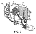
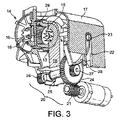
図2及び図3に示されるように、淹出ユニット2は、第1アセンブリ13と第2アセンブリ14とを有し、これらは、互いに相対的に動くことができる。
As shown in FIGS. 2 and 3, the
本発明の文脈において、「アセンブリ」は、異なる機能を集める単一コンポーネントを指しても、例えば、機械的なガイド機能、機械的な保持機能、機械的な貫通機能、流出機能、圧力機能など、更に/又は、所望の機能を集める複数のコンポーネントを指してもよい。 In the context of the present invention, an “assembly” refers to a single component that collects different functions, for example, a mechanical guide function, a mechanical retention function, a mechanical penetration function, an outflow function, a pressure function, etc. In addition, / or may refer to a plurality of components that collect the desired functionality.
例えば、第1アセンブリ13は、後部の注入用アセンブリ13であり、注入ブレード15を備えたカプセル保持器を含む。前方のアセンブリ14は、飲料配送用アセンブリを形成し、カプセル配送プレート16を含む。前方のアセンブリ14は、外部ケーシング17に関連付けられており、それと共に、後方の注入用アセンブリ13に対して移動することができ、後方の注入用アセンブリ13は、機械1のフレーム18に固定されたままである。前方の配送用アセンブリ14は、飲料出口19を含む。
For example, the
前方の配送用アセンブリ14は、伝達手段4を駆動するモータ3により、後方の注入用アセンブリ13まで動かされる。
The
本発明によると、モータ3は、50mNm以下の最大トルクを生成し、更に/又は、50ワット以下の最大電力を消費し、可動アセンブリ14を開位置と閉位置との間で駆動するように構成された低電力モータである。
According to the present invention, the motor 3 is configured to generate a maximum torque of 50 mNm or less and / or consume a maximum power of 50 watts or less and drive the
例えば、モータ3は、少なくとも20mNm、特に、25から40mNmの範囲の最大トルクを生成するようにアレンジされている。モータ3は、7から25ワット、特に、10から15ワットの範囲で最大電力を消費するようにアレンジ可能である。モータは、0から5000RPMのような、最大10K RPMの角速度を有することができる。 For example, the motor 3 is arranged to produce a maximum torque of at least 20 mNm, in particular in the range of 25 to 40 mNm. The motor 3 can be arranged to consume maximum power in the range of 7 to 25 watts, especially 10 to 15 watts. The motor can have an angular velocity of up to 10K RPM, such as 0 to 5000 RPM.
開位置(図2)において、通路31が、第1アセンブリ13と第2アセンブリ14との間に設けられ、カプセル30の挿入を可能にする。カプセルは、例えば、EP1646305又はWO2009/043630に記載されているように、中間位置に位置決めされてもよい。
In the open position (FIG. 2), a
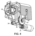
閉位置(図3)において、淹出用チャンバ29が形成される。淹出用チャンバ29は、淹出ユニットの正常に閉じた位置(図4)において、カプセル30により少なくとも部分的に占有される。カプセルは、どんな種類のカプセルでもよく、淹出ユニットの開閉中、アセンブリにより取り扱われる為に、淹出用チャンバ29及び通路31と単純に互換性がなければならない。適したカプセル及び/淹出用チャンバは、例えば、EP0512468、EP0512470、EP2068684に開示されている。
In the closed position (FIG. 3), a
伝達手段4は、様々な機械的システムを含んでもよい。伝達手段4は、少なくとも1:50,特に、1:100から1:300、1:500の、モータからアセンブリまでの力伝達比を有してもよい。 The transmission means 4 may include various mechanical systems. The transmission means 4 may have a motor-to-assembly force transmission ratio of at least 1:50, in particular 1: 100 to 1: 300, 1: 500.
図1から図4に図示された実施形態において、伝達手段4は、カム22及びカム−従動子23に結合されたギヤアセンブリ20を含む。ケーシング17上の力の、バランスのとれた伝達のため、カム22は、ケーシング17の側部の各々に配置された一対の細長い溝を備える。ギヤアセンブリ20は、ウォーム駆動部21を備え、ウォーム駆動部21は、モータ軸に(すなわち、モータ3のロータに)連結されている。ウォーム駆動部21は、大きなギヤ24(例えば、スパーギヤ又はヘリカルギヤ)を作動させるが、このギヤ24は軸25に固定され、軸25に、小さな2つの側方ギヤ26,27(例えば、スパーギヤ又はヘリカルギヤ又は摩擦ギヤ)が位置する。小さなギヤ26,27は、一対のギヤセグメント28(例えば、スパーギヤ、ヘリカルギヤ、摩擦ギヤ)を駆動し、これが、カム−従動子23を動かし、その結果、ケーシング17と共にカム22を、開位置から閉位置まで、更に、閉位置から開位置まで動かす。閉位置において、ギヤセグメント28は、カム−従動子23と共に、淹出圧力が、残りの駆動システムに(例えば、ギヤセグメントを横切って放射状に)伝達されることなく、ギヤセグメントにわたって吸収されるように位置される。しかしながら、後述するように、淹出圧力は、適した構成による駆動システムにより吸収可能である。
In the embodiment illustrated in FIGS. 1-4, the transmission means 4 includes a
ウォーム駆動部21と大きなギヤ24とのギヤ比は、1:25から1:100の範囲(例えば、1:50,1:80)でもよい。小さなギヤ27とギヤセグメント28とのギヤ比は、1:3から1:10の範囲(特に、1:5から1:8の範囲)でもよい。
The gear ratio between the
例えば、ウォーム駆動部21を伝達装置4で使用することにより、この伝達を一方向にすることができる。換言すると、力と運動は、モータ3から伝達装置4に伝達されるだけであり、逆には伝達されず、ウォーム駆動部21は、反対方向においては歯止めとして作用する。このため、所定位置にアセンブリを維持する為に、更なる歯止め手段は不要である。所定位置、特に、閉位置又は開位置にアセンブリ13,14を固定することは、モータの電力供給を妨害するのに十分である。
For example, the transmission can be unidirectional by using the
あり得る解決策において、開位置及び閉位置の両方の位置は、端部スイッチやセンサを持たない「ハードな歯止め」として幾何学的に形成される。 In a possible solution, both the open and closed positions are geometrically formed as “hard pawls” without end switches or sensors.
モータ制御に対する入力は、ユーザーインターフェース、モータの電流吸収、制御ユニットのタイマを含む。 Inputs for motor control include user interface, motor current absorption, and control unit timer.
図5に図示されるように、2つの異なる典型的な曲線40,41は、特に、モータ3がDCモータであって、例えば、ほぼ一定電圧で作動されるとき、例えば、モータ3の電力消費を測定することにより(例えば、モータ3の電流消費を測定することにより)、時間にわたって検出可能である。
As illustrated in FIG. 5, two different
曲線40は、「カプセル閉鎖モード」におけるモータ3の電流消費の、時間にわたる変化を示す。カプセル閉鎖モードにおける淹出ユニット2の閉鎖状態は、閉じられた淹出用チャンバ内に囲まれたカプセル30と共に図4に表されている。
曲線41は、「空の」閉鎖モードにおけるモータ3の電流消費の変化を表す。空の閉鎖モードにおける淹出ユニット2の閉鎖状態は、図3に表されている。
このため、曲線40、41は、淹出ユニット2のアセンブリ13、14の閉鎖運動に対応する。同様に、曲線は、例えば、アセンブリ13、14間のカプセル30の有無に拘わらず、開放運動の為に確定可能である。そのような開放曲線は、アセンブリ13,14の開放運動の、あり得る障害(例えば、当該機械のハウジングと、その中の淹出ユニット2の可動アセンブリとの間の指のような、人体の一部のジャム)を検出する為に設定基準として、使用可能である。
Thus, the
機械1の制御ユニット10は、淹出ユニットが携わっている関連モードに依存し、実際の電流消費の変動を基準曲線40、41と比較する為に構成される。そのような構成は、ソフトウェアにより得られる。
The
カプセル30が淹出ユニット2に挿入され、曲線40との比較において、電流の吸収について異常な変動が何も検出されないならば、例えば、典型的な電流消費曲線40の20%を超える変動が無いならば、淹出サイクルを始めることができる。淹出サイクルの開始は、ユーザーのインターフェース12における要求又はコマンドにより始動可能である。あるいは、淹出サイクルの開始は、閉鎖位置の到達により、自動的に始動可能である。
If the
何もカプセルが淹出用チャンバ2に挿入されず、曲線41との比較において、電流吸収の変動について異常な変動が何も検出されないならば、低温で最適な湯垢除去及び/又はエネルギ節約を許容する為に、湯垢除去モード及び/又は洗浄モードが、閉鎖位置(図3)において始められる。洗浄及び/又は湯垢除去サイクルの開始は、また、ユーザーのインターフェースにおける要求又はコマンドにより始動可能である。あるいは、洗浄及び/又は湯垢除去サイクルの開始は、閉鎖位置の到達により自動的に始動可能である。何もカプセルが淹出用チャンバ2に挿入されず、曲線41との比較において、電流吸収の変動について異常な変動が何も検出されないならば、カップ−予熱モードをはじめてもよいが、これは、飲料を調製及び注出する前に、その予熱の為に、お湯をユーザーカップに注出することを含む。カップの予熱は、飲料の調製温度又は低温において、実行されてもよい。
If no capsules are inserted into the
より具体的には、曲線40は、カプセル30が淹出ユニット2に挿入されるとき、時間に対して、モータ3による時間にわたる電流消費の例示的変化を図示し、様々な局面を含む。
More specifically, the
初期部分401、すなわち、電流消費の急増は、可動アセンブリの移動の開始、特に、静的な摩擦力を克服する為に必要な電力消費を反映する。第2の部分402は、部分401の最上部より僅かに下方のレベルで開始し(動的摩擦力は、静的摩擦力より下方にある)、緩やかに増加する。この部分は、閉鎖中の淹出用チャンバ29に次第に入るカプセル30により生じる抵抗の増加を図示する。最大値403は、カプセル30が中間位置から押し出されるときに達し、この中間位置において、カプセルは、例えば、EP2103236に説明されているような歯止め部材により支持される。その後、電流消費は、それが最小値404に達するまで、僅かに降下する。電流消費405,406,407は、閉鎖中のブレード15によるカプセル30の変形及び漸進的貫通のため、増加する。だいたいの平坦部分408は、アセンブリの最終的導入を表す。電流増加409は、閉鎖位置におけるアセンブリ間で受け取りを果たす為に、付勢バネ(図示せず)に応力を加えるのに必要な電力を反映する。いったん、電流消費が最大値410に達すると、最大電力がモータ3により消費されるが、これは、モータ3が妨げられ、アセンブリが閉鎖位置にあることを表す。
The
何もカプセルが淹出ユニット2に挿入されないとき、時間にわたりモータ3による電流消費の例示的変化を図示する曲線41は、様々な局面を含む。
A
部分411は、部分401、すなわち、可動アセンブリの移動に対応する。いったんアセンブリが移動すると、部分412,413,414は、回転するカムと、直線溝内を移動する従動子23と、溝22の方向に対しほぼ直交して移動するアセンブリ13の力分布を本質的に図示する。部分416,417は、付勢バネに応力を加える為の電力消費増加を図示する。前述のように、いったん電流消費が最大値417に達すると、最大電力は、モータ3により消費されるが、これは、モータに対する抵抗が完了し、アセンブリが閉鎖位置にあることを示す。
一例として図5に図示されるように、何もカプセルが淹出ユニット2に挿入されないとき、アセンブリを閉鎖する為に必要な時間は、モータ3がカプセル3の存在により生じる追加の力を克服しなければならないときより、およそ0.5秒だけ短くなる。全体的に、閉鎖は、本発明の特定の実施形態と共に図示されたように、2秒から2.5秒以内に達成可能である。
As illustrated by way of example in FIG. 5, when no capsule is inserted into the
淹出ユニットのアセンブリの開閉に必要な時間は、通常、1秒から10秒の範囲内でもよい。 The time required to open and close the brewing unit assembly may typically be in the range of 1 to 10 seconds.
電流吸収の測定が、前述した2つの曲線40,41と合致しないとき、特に、電流消費が、閉鎖位置に達する前の曲線を著しく越えるとき、望ましくない障害物がアセンブリ間に置かれたり、或いは、システムがジャム又は他の故障を起こすことが予想される。それゆえに、安全入力が作動可能になる。安全入力は、可動アセンブリを開位置に戻す為にモータの作用を逆にする動作を備えることが好ましい。あるいは、安全入力は、モータの駆動作用を減少或いは停止させることと同然であってもよい。この安全処置は、例えば、ユーザーが、動作中の機構に指を詰まらせることから保護する。例えば、アセンブリの閉鎖に対する抵抗が、閉位置に達する前に、50,80,100,125又は150Nを超えるとき、安全入力が始動されてもよい。例えば、1又は2mm、特に、3mm又は4mmを超える閉鎖前のアセンブリ間の距離で過剰な抵抗が生じるとき、安全入力が始動されてもよい。
When current absorption measurements do not match the two
ギヤアセンブリは、少なくとも1:100、好ましくは、1:250と1:450との間(例えば、1:300)のように、1:200と1:500との間のギヤ比を与えるように構成されるのが好ましい。この比較的に高いギヤ比のため、本発明の他の利点は、比較的に低い電力モータ、例えば、20−50mNmの使用可能性から生まれる。 The gear assembly provides a gear ratio between 1: 200 and 1: 500, such as at least 1: 100, preferably between 1: 250 and 1: 450 (eg 1: 300). Preferably it is configured. Due to this relatively high gear ratio, another advantage of the present invention arises from the availability of a relatively low power motor, for example 20-50 mNm.
1 飲料機
2 淹出ユニット
3 電気モータ
4 伝達手段(伝達装置)
5 給水手段
6 水リザーバ(水ポンプ)
7 ポンプ
8 水ヒータ
9 水循環路
10 制御手段(制御ユニット)
11 制御手段(制御ユニット)
12 ユーザーインターフェース
13 注入用アセンブリ
14 配送用アセンブリ(可動アセンブリ)
15 注入ブレード
16 カプセル配送プレート
17 外部ケーシング
18 フレーム
19 飲料出口
20 ギヤアセンブリ
21 ウォーム駆動部
22 カム
22 溝
23 従動子
24 ギヤ
25 軸
26,27 側方ギヤ
28 ギヤセグメント
29 淹出用チャンバ
30 カプセル
31 通路
40 基準曲線(電流消費曲線)
41 曲線
1
5 Water supply means 6 Water reservoir (water pump)
7 Pump 8 Water heater 9
11 Control means (control unit)
12
15
41 Curve
Claims (15)
−モータ(3)を備える作動手段と、
−共に協働する第1アセンブリ(13)及び第2アセンブリ(14)を備える淹出ユニット(2)であって、各アセンブリが、原料用カプセル(30)を含む為の淹出用チャンバ(29)の一部を限定する、淹出ユニットと、
を有し、
少なくとも一つの前記アセンブリ(14)が、
−前記アセンブリ間に通路(31)を形成し、前記原料用カプセルを前記淹出ユニットの中に挿入し、更に/又は、前記原料用カプセルを前記淹出ユニットから取り外す為に、前記飲料機の内部で協働するアセンブリ(13)から離れて開位置に動くことができ、
−前記淹出用チャンバを形成する為に、前記協働するアセンブリへと閉位置に動くことができ、
前記モータが、低電力モータであって、
−50mNm以下の最大トルクを生成し、
更に/又は、
−50W以下の最大電力を消費し、
前記可動アセンブリを前記開位置と閉位置との間で駆動することを特徴とする、モータ付き飲料機 A beverage machine with a motor (1),
An actuating means comprising a motor (3);
A brewing unit (2) comprising a first assembly (13) and a second assembly (14) cooperating together, each brewing chamber (29) for containing a raw material capsule (30) ) With a limited unit,
Have
At least one of said assemblies (14),
-Forming a passageway (31) between the assemblies, inserting the ingredient capsules into the brewing unit and / or removing the ingredient capsules from the brewing unit; Move away from the internally cooperating assembly (13) to the open position;
-Can be moved to a closed position into the cooperating assembly to form the brewing chamber;
The motor is a low power motor,
Produces a maximum torque of -50 mNm or less,
And / or
Consumes maximum power of -50W or less,
The motorized beverage machine, wherein the movable assembly is driven between the open position and the closed position.
−お湯を前記淹出用チャンバに供給する為の給水手段(5)と、
−前記モータ(3)の前記駆動作用を制御する為の制御手段(10)であって、任意で前記制御手段(10)が、前記開位置及び/又は閉位置に端部位置センサを持たない、前記制御手段と、
を更に備える、請求項1〜9のいずれか一項に記載の飲料機。 The operating means is
A water supply means (5) for supplying hot water to the brewing chamber;
-Control means (10) for controlling the drive action of the motor (3), optionally the control means (10) does not have an end position sensor in the open position and / or closed position; The control means;
The beverage machine according to any one of claims 1 to 9, further comprising:
−前記モータによる電力の消費を表す少なくとも一つの電気的パラメータを測定する為の手段と、
−前記開位置から前記閉位置への前記アセンブリの移動中の時間の関数として、前記測定されたパラメータの変化を設定基準(40,41)と比較する為の手段と、
−前記測定されたパラメータの前記変化と前記設定基準との比較から生じる入力を前記作動手段のうち少なくとも一つに与える為の手段と、
を備える、請求項10に記載の飲料機。 The control means (10)
-Means for measuring at least one electrical parameter representative of power consumption by the motor;
Means for comparing the measured parameter change as a function of time during the movement of the assembly from the open position to the closed position with a set criterion (40, 41);
-Means for providing to at least one of said actuating means an input resulting from a comparison of said change in said measured parameter with said set criteria;
The beverage machine according to claim 10, comprising:
−前記設定基準(40、41)より少なくとも20%以上、特に30又は40%以上、例えば50%以上のレベルを超え、
更に/又は、
−前記閉位置に向かって動くアセンブリの間で、そこに到達する前に、障害物、特に指のような人体の一部の存在により引き起こされる閉鎖に対する抵抗に対応するとき、異常とみなされる、請求項11に記載の飲料機。 When abnormal, when detecting a variation of the measured parameter relative to the set criteria (40, 41), a safety input is provided to the motor (3), the variation being the measured parameter But,
-Exceeding a level of at least 20%, in particular 30 or 40%, for example 50% or more above the set criteria (40, 41)
And / or
Between assembly moving towards said closed position, before reaching it, it is considered abnormal when it corresponds to the resistance to closure caused by the presence of obstacles, in particular parts of the human body like fingers, The beverage machine according to claim 11.
−原料用カプセル(30)が前記淹出用チャンバ(29)に挿入される閉位置に前記可動アセンブリ(14)が動かされるモード、
及び/又は、
−何もカプセルが前記淹出用チャンバに挿入されない閉位置に前記可動アセンブリが動かされるモードに対応する、時間の関数として前記電気的パラメータの正常な変化を表す基準曲線(40、41)との比較において異常な変動を検出するように構成される、請求項13に記載の飲料機。 The control means (10)
A mode in which the movable assembly (14) is moved to a closed position where the raw capsule (30) is inserted into the brewing chamber (29);
And / or
A reference curve (40, 41) representing a normal change in the electrical parameter as a function of time, corresponding to a mode in which the movable assembly is moved to a closed position where no capsule is inserted into the brewing chamber 14. A beverage machine according to claim 13, configured to detect abnormal fluctuations in the comparison.
Applications Claiming Priority (3)
| Application Number | Priority Date | Filing Date | Title |
|---|---|---|---|
| EP10174412.6 | 2010-08-27 | ||
| EP10174412 | 2010-08-27 | ||
| PCT/EP2011/057235 WO2012025259A1 (en) | 2010-08-27 | 2011-05-05 | Simple motorized brewing unit |
Publications (2)
| Publication Number | Publication Date |
|---|---|
| JP2013539384A true JP2013539384A (en) | 2013-10-24 |
| JP2013539384A5 JP2013539384A5 (en) | 2014-06-19 |
Family
ID=44065470
Family Applications (2)
| Application Number | Title | Priority Date | Filing Date |
|---|---|---|---|
| JP2013525194A Active JP5871927B2 (en) | 2010-08-27 | 2011-05-05 | Controlled motorized feeding unit |
| JP2013525195A Pending JP2013539384A (en) | 2010-08-27 | 2011-05-05 | Simple motorized brewing unit |
Family Applications Before (1)
| Application Number | Title | Priority Date | Filing Date |
|---|---|---|---|
| JP2013525194A Active JP5871927B2 (en) | 2010-08-27 | 2011-05-05 | Controlled motorized feeding unit |
Country Status (17)
| Country | Link |
|---|---|
| US (2) | US10285534B2 (en) |
| EP (3) | EP2608705B2 (en) |
| JP (2) | JP5871927B2 (en) |
| KR (2) | KR20130095757A (en) |
| CN (2) | CN103209622B (en) |
| AU (2) | AU2011295341C1 (en) |
| BR (2) | BR112013004767B1 (en) |
| CA (2) | CA2809078C (en) |
| CH (1) | CH705749B1 (en) |
| DE (1) | DE112011102829T5 (en) |
| DK (1) | DK201300013U4 (en) |
| ES (3) | ES2546489T3 (en) |
| MX (2) | MX341681B (en) |
| PT (3) | PT2608704T (en) |
| RU (1) | RU2560911C2 (en) |
| WO (2) | WO2012025259A1 (en) |
| ZA (2) | ZA201302271B (en) |
Families Citing this family (83)
| Publication number | Priority date | Publication date | Assignee | Title |
|---|---|---|---|---|
| EP2608705B2 (en) * | 2010-08-27 | 2024-03-06 | Société des Produits Nestlé S.A. | Controlled motorized brewing unit |
| JP2014504513A (en) * | 2011-01-03 | 2014-02-24 | ネステク ソシエテ アノニム | Electric beverage machine with mechanical transmission |
| ITVR20110179A1 (en) * | 2011-09-19 | 2013-03-20 | Caffita System Spa | INFUSION DEVICE FOR THE PRODUCTION OF DRINKS BY USING CARTRIDGES, WHICH CARTRIDGES OR PODS |
| ITVR20110180A1 (en) | 2011-09-19 | 2013-03-20 | Caffita System Spa | INFUSION DEVICE FOR THE PRODUCTION OF DRINKS BY USING CARTRIDGES, WHICH CAPSULES OR PODS |
| US20150056343A1 (en) | 2012-02-28 | 2015-02-26 | Nestec S.A. | Capsule-controlled motorized brewing unit |
| BR112015007498A2 (en) | 2012-10-09 | 2017-07-04 | Nestec Sa | extraction unit with a multi-size mobile cartridge receiver |
| US9955815B2 (en) | 2012-10-09 | 2018-05-01 | Nestec S.A. | Extraction unit with multi-size cartridge cavity |
| RU2628716C2 (en) | 2012-10-09 | 2017-08-21 | Нестек С.А. | Machine for preparing beverages |
| ES2786131T3 (en) | 2012-12-19 | 2020-10-08 | Nestle Sa | Self-locking multi-dimensional cartridge removal unit |
| ES2676459T3 (en) | 2012-12-20 | 2018-07-19 | Nestec S.A. | Double ramp to close a receptacle holder |
| US9955813B2 (en) | 2012-12-20 | 2018-05-01 | Nestec S.A. | Variable transmission for closing a receptacle holder |
| ES2605107T3 (en) | 2012-12-21 | 2017-03-13 | Delica Ag | Device for the preparation of a drink |
| US20160120357A1 (en) * | 2013-05-29 | 2016-05-05 | Nestec S.A. | Beverage mixing device |
| BE1021777B1 (en) * | 2013-06-25 | 2016-01-18 | Tconcept Company S.P.R.L. | DEVICE FOR PREPARING INFUTED BEVERAGES COMPRISING A POSITIONING MEANS FOR THE CAPSULE |
| WO2015086371A1 (en) | 2013-12-11 | 2015-06-18 | Nestec S.A. | Beverage machine with a pivotable capsule gate |
| EP3119246A1 (en) | 2014-03-19 | 2017-01-25 | Nestec S.A. | Beverage machine with exchangeable outermost panels |
| WO2015155145A1 (en) | 2014-04-08 | 2015-10-15 | Nestec S.A. | Multisize capsule handling with serial actuation |
| US9880526B2 (en) * | 2014-05-07 | 2018-01-30 | Regal Beloit America, Inc. | System and method for automating ancillary devices using a motor controller for a pump |
| WO2015173123A1 (en) * | 2014-05-12 | 2015-11-19 | Nestec S.A. | Beverage brewing unit particularly for machines for preparing beverages from capsules |
| EP3166456B1 (en) | 2014-07-09 | 2018-09-26 | Nestec S.A. | Accessory for supplying automatically a beverage machine with liquid from a distribution network |
| WO2016005351A1 (en) | 2014-07-09 | 2016-01-14 | Nestec S.A. | Coupling of a device for connecting a beverage machine to a distribution network |
| WO2016005348A1 (en) | 2014-07-09 | 2016-01-14 | Nestec S.A. | Device for connecting a beverage machine to a distribution network with safe flow interruption |
| PT3166457T (en) | 2014-07-09 | 2020-01-20 | Nestle Sa | Device for connecting a beverage machine to a distribution network with safe monitoring |
| KR102293489B1 (en) * | 2014-09-12 | 2021-08-27 | 코웨이 주식회사 | Coffee machine and preheating method thereof |
| CA3207639A1 (en) * | 2014-10-20 | 2016-04-28 | Bedford Systems Llc | Cartridge holder for beverage machine |
| US11076714B2 (en) | 2014-11-27 | 2021-08-03 | Societe Des Produits Nestle S.A. | Liquid dispensing machine with manual drop stop |
| WO2016083488A1 (en) | 2014-11-27 | 2016-06-02 | Nestec S.A. | Liquid dispensing machine with compact drop stop |
| US11026539B2 (en) * | 2015-05-07 | 2021-06-08 | Smart Wave Technologies, Inc. | Signal and detection system for pairing products |
| WO2017046294A1 (en) | 2015-09-18 | 2017-03-23 | Nestec S.A. | Removal of a capsule from a capsule holder |
| ITUB20154199A1 (en) | 2015-10-07 | 2017-04-07 | Carpigiani Group Ali Spa | MACHINE AND METHOD FOR THE REALIZATION OF LIQUID AND SEMILIQUID PRODUCTS OF THE HOT OR COLD TYPE. |
| CA3001089A1 (en) | 2015-11-11 | 2017-05-18 | Nestec S.A. | Easy connection of a liquid tank to a beverage machine |
| EP3175747A1 (en) * | 2015-12-03 | 2017-06-07 | Qbo Coffee GmbH | Machine for making beverages |
| RU2760900C2 (en) * | 2016-06-30 | 2021-12-01 | Сосьете Де Продюи Нестле С.А. | Apparatus for preparing a beverage with a controlled pump |
| IT201600074471A1 (en) | 2016-07-15 | 2018-01-15 | Ali Group Srl Carpigiani | MACHINE AND METHOD FOR THE PRODUCTION OF LIQUID AND SEMIQUID PRODUCTS OF THE ICE CREAM, PASTRY OR RESTAURANT SECTOR. |
| EP3509464B1 (en) * | 2016-09-09 | 2021-08-18 | Société des Produits Nestlé S.A. | Beverage machine with ergonomic handling |
| IT201600100869A1 (en) * | 2016-10-07 | 2018-04-07 | Ali Group Srl Carpigiani | METHOD AND CLEANING SYSTEM OF A MACHINE FOR THE REALIZATION OF LIQUID AND / OR SEMIQUINE FOODSTUFFS IN THE ICE-CREAM, PASTRY OR RESTAURANT SECTOR |
| AU2017343599B2 (en) | 2016-10-11 | 2023-02-02 | Société des Produits Nestlé S.A. | Liquid dispensing machine with drop stop |
| CA3034163A1 (en) | 2016-10-11 | 2018-04-19 | Nestec S.A. | Liquid dispensing machine with speed regulator |
| CA3041722A1 (en) | 2016-11-09 | 2018-05-17 | Pepsico, Inc. | Carbonated beverage makers, methods, and systems |
| US11643269B2 (en) | 2016-12-01 | 2023-05-09 | Bedford Systems, LLC | Container and opening arrangement for beverage production |
| CN110312453A (en) | 2017-02-28 | 2019-10-08 | 雀巢产品有限公司 | Distributor with parallel distribution path |
| EP3387966A1 (en) | 2017-04-11 | 2018-10-17 | Nestec S.A. | Beverage preparation device for vehicle |
| EP3609375A1 (en) | 2017-04-11 | 2020-02-19 | Société des Produits Nestlé S.A. | Beverage preparation apparatus with beverage draining means |
| EP3609372B1 (en) | 2017-04-11 | 2021-01-20 | Société des Produits Nestlé S.A. | Beverage preparation device with beverage draining means |
| IT201700043975A1 (en) | 2017-04-21 | 2018-10-21 | Ali Group Srl Carpigiani | MACHINE AND METHOD FOR THE PRODUCTION OF LIQUID AND SEMIQUID PRODUCTS OF THE ICE CREAM SECTOR. |
| CN110691538B (en) | 2017-06-01 | 2023-03-28 | 雀巢产品有限公司 | Beverage machine with collapsible interface |
| CN110662468B (en) | 2017-06-01 | 2022-04-29 | 雀巢产品有限公司 | Beverage machine with ergonomic power switch |
| US20200129002A1 (en) | 2017-06-01 | 2020-04-30 | Societe Des Produits Nestle S.A. | Beverage machine with a storable dispensing head |
| EP3629854A1 (en) | 2017-06-01 | 2020-04-08 | Société des Produits Nestlé S.A. | Beverage machine with a stablizing foot |
| AU2018283446A1 (en) | 2017-06-13 | 2019-10-31 | Societe Des Produits Nestle S.A. | Beverage preparation machine with capsule recognition |
| WO2019057619A1 (en) | 2017-09-25 | 2019-03-28 | Nestec Sa | Beverage machines with modularity |
| EP3687347B1 (en) | 2017-09-25 | 2023-07-26 | Société des Produits Nestlé S.A. | Beverage machines with a removable module |
| EP3501349A1 (en) * | 2017-12-21 | 2019-06-26 | Koninklijke Philips N.V. | A coffee machine with integrated steam and hot water generation |
| EP3749154A1 (en) | 2018-02-09 | 2020-12-16 | Société des Produits Nestlé S.A. | Beverage preparation machine with capsule recognition |
| CN111801035B (en) | 2018-03-14 | 2023-04-21 | 雀巢产品有限公司 | Beverage machine with partially open dispensing face |
| EP3764855A1 (en) | 2018-03-14 | 2021-01-20 | Société des Produits Nestlé S.A. | Beverage machine with a partly closed dispensing face |
| US11363907B2 (en) | 2018-03-14 | 2022-06-21 | Societe Des Produits Nestle S.A. | Beverage machine with a controlled capsule piercing |
| AU2019233584A1 (en) | 2018-03-14 | 2020-08-06 | Societe Des Produits Nestle S.A. | Beverage extraction unit with movable outflow obstructor |
| JP2021515623A (en) | 2018-03-14 | 2021-06-24 | ソシエテ・デ・プロデュイ・ネスレ・エス・アー | Beverage machine with controlled outflow opening |
| BR112020015429A2 (en) | 2018-03-14 | 2020-12-08 | Société des Produits Nestlé S.A. | DRINK EXTRACTION UNIT TO SELECTIVELY PROVIDE HOLES OF DIFFERENT TYPES IN A CAPSULE FOR DRINK EXTRACTION |
| EP3768127B1 (en) * | 2018-03-22 | 2023-12-06 | Bedford Systems LLC | Puncture mechanism for beverage machine |
| WO2020064982A1 (en) | 2018-09-27 | 2020-04-02 | Société des Produits Nestlé SA | Adaptive service unit of a beverage machine |
| EP4248808A3 (en) | 2018-09-27 | 2023-10-04 | Société des Produits Nestlé S.A. | Beverage machine with an actuation distribution |
| EP3628195A1 (en) | 2018-09-27 | 2020-04-01 | Société des Produits Nestlé S.A. | Beverage preparation machine with recipient detection |
| FR3088435B1 (en) * | 2018-11-09 | 2020-11-06 | Cie Mediterraneenne Des Cafes | DEVICE AND METHOD FOR DETECTION OF AN ANOMALY IN THE CLOSURE OF AN INFUSION GROUP |
| AU2019400059A1 (en) | 2018-12-12 | 2021-05-20 | Société des Produits Nestlé SA | Beverage preparation machine with capsule recognition |
| IT201900008844A1 (en) | 2019-06-13 | 2020-12-13 | Lavazza Luigi Spa | Motorized infusion unit |
| WO2021096376A1 (en) * | 2019-11-15 | 2021-05-20 | Novadelta - Comércio E Indústria De Cafés, Lda | Systems and methods for preparing beverages with improved motorized actuation regulation |
| AU2021217123A1 (en) | 2020-02-05 | 2022-06-30 | Societe Des Produits Nestle S.A. | Beverage preparation machine with capsule recognition |
| US20230038172A1 (en) | 2020-02-05 | 2023-02-09 | Societe Des Produits Nestle S.A. | Beverage preparation machine with capsule recognition |
| FR3110065A1 (en) * | 2020-05-13 | 2021-11-19 | Compagnie Mediterraneenne Des Cafes | METHOD AND DEVICE FOR DETECTION AT THE TIME OF A STUCK DOSE |
| CN111616591B (en) * | 2020-05-21 | 2022-04-08 | 四川虹美智能科技有限公司 | Tea brewing device |
| CA3233465A1 (en) | 2021-10-13 | 2023-04-20 | Laurent LAGOUCHE | Ergonomic beverage machine |
| IT202100031811A1 (en) * | 2021-12-20 | 2023-06-20 | Citaly Srl | Infusion group for coffee preparation machines |
| AU2022418174A1 (en) | 2021-12-22 | 2024-05-09 | Société des Produits Nestlé S.A. | Beverage preparation by centrifugation with reliable capsule transfer |
| AU2022422173A1 (en) | 2021-12-22 | 2024-05-09 | Société des Produits Nestlé S.A. | Beverage preparation by stable capsule centrifugation |
| WO2023118246A1 (en) | 2021-12-22 | 2023-06-29 | Société des Produits Nestlé S.A. | Beverage preparation with a flexible outlet valve |
| AU2022419166A1 (en) | 2021-12-22 | 2024-05-09 | Société des Produits Nestlé S.A. | Beverage preparation with compact conditioning chamber |
| AU2022422172A1 (en) | 2021-12-22 | 2024-05-02 | Société des Produits Nestlé S.A. | Beverage preparation with a stable outlet valve |
| US20240162369A1 (en) | 2021-12-22 | 2024-05-16 | M10 Solar Equipment GmbH | Process and apparatus for manufacturing solar panels |
| WO2023198819A1 (en) | 2022-04-14 | 2023-10-19 | Société des Produits Nestlé S.A. | Centrifugal chamber with capsule opening elements |
| WO2023198821A1 (en) | 2022-04-14 | 2023-10-19 | Société des Produits Nestlé S.A. | Centrifugal beverage chamber with closure fastener |
| WO2023198823A1 (en) | 2022-04-14 | 2023-10-19 | Société des Produits Nestlé S.A. | Centrifugal chamber with capsule positioning guide |
Citations (4)
| Publication number | Priority date | Publication date | Assignee | Title |
|---|---|---|---|---|
| JPH04210009A (en) * | 1990-12-12 | 1992-07-31 | Matsushita Electric Ind Co Ltd | Electric coffee boiler |
| JPH0743772U (en) * | 1990-02-17 | 1995-09-12 | フィリップス エレクトロニクス ネムローゼ フェンノートシャップ | Pressure pump |
| US7210401B1 (en) * | 2004-04-20 | 2007-05-01 | Rolfes Patrick J | Single cup pod beverage brewer |
| JP2010519009A (en) * | 2007-02-27 | 2010-06-03 | サエコ アイピーアール リミテッド | Method for automatically adjusting the amount of coffee and coffee machine using the method |
Family Cites Families (69)
| Publication number | Priority date | Publication date | Assignee | Title |
|---|---|---|---|---|
| US2868109A (en) * | 1954-12-13 | 1959-01-13 | James F Davis | Coffee maker |
| US3306183A (en) * | 1964-07-13 | 1967-02-28 | Levine Alfred B | Beverage infusion machine |
| DE3101511A1 (en) | 1981-01-19 | 1982-08-26 | Siemens AG, 1000 Berlin und 8000 München | METHOD AND ARRANGEMENT FOR DETERMINING THE LOAD OF DEVICES DRIVEN BY AN ELECTRIC MOTOR |
| IT1171006B (en) | 1983-03-03 | 1987-06-10 | Fiat Auto Spa | SAFETY CIRCUIT FOR THE ELECTRIC CONTROL OF A GROUP OF DRIVING WINDOWS ON VEHICLES |
| JPH0743772Y2 (en) | 1989-03-20 | 1995-10-09 | 三洋電機株式会社 | Rotating cylinder device |
| JPH03239174A (en) | 1990-02-16 | 1991-10-24 | Jidosha Denki Kogyo Co Ltd | Wiper control system |
| TW199884B (en) * | 1991-05-08 | 1993-02-11 | Sociere Des Produits Nestle S A | |
| AU1505192A (en) | 1991-05-10 | 1992-11-12 | Societe Des Produits Nestle S.A. | Sealed cartridge for the prepartion of a beverage |
| IT1250447B (en) * | 1991-07-03 | 1995-04-07 | Lucio Grossi | AUTOMATIC MACHINE FOR THE PRODUCTION OF COFFEE WITH DIRECT CURRENT MOTOR OPERATION AND ENDLESS SCREWS. |
| US5334876A (en) | 1992-04-22 | 1994-08-02 | Nartron Corporation | Power window or panel controller |
| NL9300913A (en) | 1993-05-27 | 1994-12-16 | Sara Lee De Nv | Method and device for preparing a drink. |
| US5701063A (en) | 1995-04-05 | 1997-12-23 | Ford Global Technologies, Inc. | Obstruction-sensing system for a movable member |
| ATE227536T1 (en) * | 1997-03-13 | 2002-11-15 | Egro Ag | COFFEE MACHINE |
| AU2704397A (en) | 1997-04-21 | 1998-11-13 | Compagnie Mediterraneenne Des Cafes (S.A.) | Method for transforming an espresso-coffee maker with vertical coffee extractioninto a machine with horizontal extraction and transformed machine |
| CH692443A5 (en) | 1998-01-26 | 2002-06-28 | Fianara Int Bv | Coffee machine. |
| FR2788955B1 (en) | 1999-01-28 | 2001-04-06 | Cie Mediterraneenne Des Cafes | DEVICE FOR EXTRACTING COFFEE |
| FR2792813B1 (en) | 1999-04-27 | 2001-06-29 | Cie Mediterraneenne Des Cafes | DEVICE AND METHOD FOR CONTROLLING THE CLOSURE AND OPENING OF A COFFEE MACHINE EXTRACTION CHAMBER |
| IT1310366B1 (en) * | 1999-05-04 | 2002-02-13 | Euromatik Srl | SINGLE-DOSE PODS FEEDING DEVICE PRECOMPRESSED INTO THE MACHINES FOR THE PRODUCTION OF ESPRESSO COFFEE BEVERAGES. |
| NL1014817C2 (en) * | 2000-03-31 | 2001-10-02 | Jong Duke De | Coffee maker. |
| PT1153561E (en) | 2000-05-09 | 2005-09-30 | Nestle Sa | DEVICE FOR EXTRACTION OF A SUBSTANCE |
| DE20105672U1 (en) | 2001-03-31 | 2001-09-13 | Eugster Frismag Ag Romanshorn | Espresso brewing device |
| NL1019127C2 (en) | 2001-09-21 | 2003-03-25 | Nedap Nv | Control device for shifting a panel of a vehicle. |
| EP1310199B1 (en) | 2001-11-09 | 2007-01-24 | Societe Des Produits Nestle S.A. | Device and method for selecting and extracting a cartridge for preparing a beverage |
| DK1444932T3 (en) | 2003-02-07 | 2006-06-06 | Nestec Sa | Extraction module with linear closure to produce a beverage under pressure from a capsule |
| EP1495702A1 (en) | 2003-07-10 | 2005-01-12 | Nestec S.A. | Device for the extraction of a cartridge |
| BR0303419A (en) | 2003-08-25 | 2005-05-10 | Jcae Do Brasil Ltda | Drive control system of devices powered by direct current electric motors |
| US6904840B1 (en) * | 2004-01-28 | 2005-06-14 | Grindmaster Corporation | Brewer apparatus with improved tray assembly |
| US20050193891A1 (en) * | 2004-03-08 | 2005-09-08 | Brent Garson | Espresso making apparatus and method of brewing espresso |
| FR2874164B1 (en) * | 2004-08-10 | 2006-10-06 | Cie Mediterraneenne Des Cafes | DEVICE FOR PRODUCING BEVERAGE WITH MEANS OF DETECTION |
| US7661352B2 (en) * | 2004-08-31 | 2010-02-16 | Nestec S.A. | Method and system for in-cup dispensing, mixing and foaming hot and cold beverages from liquid concentrates |
| DE102005000061A1 (en) * | 2005-05-18 | 2006-11-23 | Hilti Ag | Electrically operated tacker |
| CN101253788A (en) | 2005-07-07 | 2008-08-27 | 高通股份有限公司 | Method and apparatus for providing location information |
| DE602005010583D1 (en) * | 2005-09-27 | 2008-12-04 | Nestec Sa | Extraction module for a capsule-based beverage machine |
| JP4898825B2 (en) * | 2005-11-22 | 2012-03-21 | コーニンクレッカ フィリップス エレクトロニクス エヌ ヴィ | Coffee making equipment |
| ITLE20060009A1 (en) | 2006-03-10 | 2006-06-09 | Giovanni Spinelli | INVENTION IN THE FIELD OF COFFEE MACHINES A FAP / CAPSULES |
| PL2119385T3 (en) * | 2006-05-24 | 2011-05-31 | Nestec Sa | Brewing device for capsule with closure mechanism of variable transmission ratio |
| WO2008005131A2 (en) * | 2006-05-30 | 2008-01-10 | Robert Downs | Continuously variable transmission |
| ITMI20061232A1 (en) * | 2006-06-26 | 2007-12-27 | Saeco Ipr Ltd | METHOD OF DETECTION OF THE QUANTITY OF GRAINS IN A GRINDING DEVICE |
| KR20090076932A (en) * | 2006-09-25 | 2009-07-13 | 코닌클리케 필립스 일렉트로닉스 엔.브이. | Method for controlling a pressure of hot water which is used in a process of making espresso |
| JP5185276B2 (en) | 2006-09-26 | 2013-04-17 | ネステク ソシエテ アノニム | Extraction system for preparing beverages from cartridges |
| US7548036B2 (en) | 2006-10-10 | 2009-06-16 | Square D Company | DC motor mechanical shock protection system |
| CN201019539Y (en) * | 2007-01-10 | 2008-02-13 | 王冬雷 | Coffee machine capable of brewing coffee capsule |
| ITFI20070028A1 (en) | 2007-02-07 | 2008-08-08 | Saeco Ipr Ltd | INFUSION DEVICE FOR THE PREPARATION OF DRINKS FROM SINGLE-DOSE CAPSULES WITH A CAPSULES CENTERING DEVICE. |
| DE202007005791U1 (en) | 2007-04-21 | 2008-08-21 | Wik Far East Ltd. | Brewing unit for a coffee machine and coffee machine with such a brewing unit |
| US7589942B2 (en) | 2007-06-15 | 2009-09-15 | General Electric Company | MEMS based motor starter with motor failure detection |
| CN201061463Y (en) * | 2007-07-23 | 2008-05-21 | 王冬雷 | Device for preparing hot beverage |
| DK2027799T3 (en) * | 2007-08-22 | 2011-06-27 | Delica Ag | Device for building a liquid food or enjoyment |
| EP2039293A1 (en) * | 2007-09-19 | 2009-03-25 | F. Hoffman-la Roche AG | Combination drive for a sample extraction system for obtaining a liquid sample |
| PL2205133T3 (en) | 2007-10-04 | 2011-10-31 | Nestec Sa | Beverage brewing unit |
| DE102008005362B4 (en) | 2008-01-21 | 2009-11-12 | BSH Bosch und Siemens Hausgeräte GmbH | Coffee machine with service indicator |
| ES2371736T3 (en) * | 2008-04-07 | 2012-01-09 | Nestec S.A. | DEVICE FOR THE PREPARATION OF DRINKS WITH THE INRUSTRATION ELIMINATION SYSTEM ONLINE AND THE INCRUSTATION ELIMINATION METHOD USING SUCH SYSTEM. |
| RU2517804C2 (en) * | 2008-08-08 | 2014-05-27 | Нестек С.А. | Beverage preparation machine equipped with carrying handle, having adaptable appearance and replaceable side panels |
| DE102008048252A1 (en) * | 2008-09-12 | 2010-04-15 | Eppendorf Ag | pipetting |
| US20100098823A1 (en) | 2008-10-20 | 2010-04-22 | Chris Nenov | Portable electrical piston-driven espresso machine |
| EP2196115A1 (en) * | 2008-12-12 | 2010-06-16 | Jura Elektroapparate AG | Drive for a coffee brewing device and coffee brewing device |
| CN101536874B (en) * | 2009-04-25 | 2011-07-27 | 广东新宝电器股份有限公司 | Coffee machine for brewing coffee capsules |
| CN201452867U (en) | 2009-04-25 | 2010-05-12 | 广东新宝电器股份有限公司 | Coffee machine for brewing coffee capsules |
| CN101606825B (en) * | 2009-07-22 | 2011-03-02 | 广东新宝电器股份有限公司 | Capsule coffee machine |
| EP2608705B2 (en) | 2010-08-27 | 2024-03-06 | Société des Produits Nestlé S.A. | Controlled motorized brewing unit |
| US9155418B2 (en) * | 2010-11-15 | 2015-10-13 | Conair Corporation | Brewed beverage appliance and method |
| CN102525278A (en) * | 2010-12-15 | 2012-07-04 | 雀巢产品技术援助有限公司 | System for testing and diagnosing faults in water dispenser and method |
| JP2014504513A (en) * | 2011-01-03 | 2014-02-24 | ネステク ソシエテ アノニム | Electric beverage machine with mechanical transmission |
| WO2012123440A1 (en) * | 2011-03-14 | 2012-09-20 | Nestec S.A. | Automatic beverage machine |
| US20150056343A1 (en) | 2012-02-28 | 2015-02-26 | Nestec S.A. | Capsule-controlled motorized brewing unit |
| EP2819558B1 (en) * | 2012-02-28 | 2019-05-01 | Nestec S.A. | Cover for an ingredient inlet with moisture management |
| CN106413604A (en) * | 2014-03-12 | 2017-02-15 | 奥索斯平有限公司 | Preloaded medical struts |
| US10034573B2 (en) * | 2014-07-09 | 2018-07-31 | Nestec S. A. | Capsule processing unit of beverage preparation machine |
| DE102015217051A1 (en) * | 2015-09-07 | 2017-03-09 | Volkswagen Aktiengesellschaft | Commercial vehicle steering |
| DE102016200019A1 (en) * | 2016-01-05 | 2017-07-06 | Stabilus Gmbh | scissor drive |
-
2011
- 2011-05-05 EP EP11719510.7A patent/EP2608705B2/en active Active
- 2011-05-05 CN CN201180051873.XA patent/CN103209622B/en active Active
- 2011-05-05 JP JP2013525194A patent/JP5871927B2/en active Active
- 2011-05-05 WO PCT/EP2011/057235 patent/WO2012025259A1/en active Application Filing
- 2011-05-05 BR BR112013004767-4A patent/BR112013004767B1/en active IP Right Grant
- 2011-05-05 KR KR1020137007706A patent/KR20130095757A/en not_active Application Discontinuation
- 2011-05-05 EP EP15164569.4A patent/EP2926698B1/en active Active
- 2011-05-05 CA CA2809078A patent/CA2809078C/en active Active
- 2011-05-05 EP EP11718373.1A patent/EP2608704B1/en active Active
- 2011-05-05 MX MX2013002271A patent/MX341681B/en active IP Right Grant
- 2011-05-05 CH CH00497/13A patent/CH705749B1/en unknown
- 2011-05-05 DE DE112011102829T patent/DE112011102829T5/en not_active Ceased
- 2011-05-05 PT PT117183731T patent/PT2608704T/en unknown
- 2011-05-05 BR BR112013004688-0A patent/BR112013004688B1/en active IP Right Grant
- 2011-05-05 CA CA2809051A patent/CA2809051C/en active Active
- 2011-05-05 KR KR1020137007705A patent/KR20130095756A/en not_active Application Discontinuation
- 2011-05-05 AU AU2011295341A patent/AU2011295341C1/en active Active
- 2011-05-05 ES ES11719510.7T patent/ES2546489T3/en active Active
- 2011-05-05 US US13/819,630 patent/US10285534B2/en active Active
- 2011-05-05 RU RU2013113574/12A patent/RU2560911C2/en active
- 2011-05-05 ES ES11718373.1T patent/ES2588711T3/en active Active
- 2011-05-05 JP JP2013525195A patent/JP2013539384A/en active Pending
- 2011-05-05 PT PT117195107T patent/PT2608705E/en unknown
- 2011-05-05 AU AU2011295342A patent/AU2011295342B2/en active Active
- 2011-05-05 US US13/819,637 patent/US10631683B2/en active Active
- 2011-05-05 ES ES15164569T patent/ES2929550T3/en active Active
- 2011-05-05 CN CN201180051930.4A patent/CN103179890B/en active Active
- 2011-05-05 PT PT151645694T patent/PT2926698T/en unknown
- 2011-05-05 MX MX2013002272A patent/MX365198B/en active IP Right Grant
- 2011-05-05 WO PCT/EP2011/057233 patent/WO2012025258A1/en active Application Filing
-
2013
- 2013-01-31 DK DKBA201300013U patent/DK201300013U4/en not_active IP Right Cessation
- 2013-03-26 ZA ZA2013/02271A patent/ZA201302271B/en unknown
- 2013-03-26 ZA ZA2013/02273A patent/ZA201302273B/en unknown
Patent Citations (4)
| Publication number | Priority date | Publication date | Assignee | Title |
|---|---|---|---|---|
| JPH0743772U (en) * | 1990-02-17 | 1995-09-12 | フィリップス エレクトロニクス ネムローゼ フェンノートシャップ | Pressure pump |
| JPH04210009A (en) * | 1990-12-12 | 1992-07-31 | Matsushita Electric Ind Co Ltd | Electric coffee boiler |
| US7210401B1 (en) * | 2004-04-20 | 2007-05-01 | Rolfes Patrick J | Single cup pod beverage brewer |
| JP2010519009A (en) * | 2007-02-27 | 2010-06-03 | サエコ アイピーアール リミテッド | Method for automatically adjusting the amount of coffee and coffee machine using the method |
Also Published As
Similar Documents
| Publication | Publication Date | Title |
|---|---|---|
| JP5871927B2 (en) | Controlled motorized feeding unit | |
| AU2013201040B2 (en) | Capsule-controlled motorized brewing unit | |
| EP2819558B1 (en) | Cover for an ingredient inlet with moisture management | |
| RU2574970C2 (en) | Mechanised beverage preparation device | |
| AU2013201039A1 (en) | Controlled motorized brewing unit | |
| TW201350064A (en) | Capsule-controlled motorized brewing unit |
Legal Events
| Date | Code | Title | Description |
|---|---|---|---|
| A524 | Written submission of copy of amendment under article 19 pct |
Free format text: JAPANESE INTERMEDIATE CODE: A524 Effective date: 20140501 |
|
| A621 | Written request for application examination |
Free format text: JAPANESE INTERMEDIATE CODE: A621 Effective date: 20140501 |
|
| A977 | Report on retrieval |
Free format text: JAPANESE INTERMEDIATE CODE: A971007 Effective date: 20150317 |
|
| A131 | Notification of reasons for refusal |
Free format text: JAPANESE INTERMEDIATE CODE: A131 Effective date: 20150421 |
|
| A601 | Written request for extension of time |
Free format text: JAPANESE INTERMEDIATE CODE: A601 Effective date: 20150721 |
|
| A521 | Request for written amendment filed |
Free format text: JAPANESE INTERMEDIATE CODE: A523 Effective date: 20150728 |
|
| A02 | Decision of refusal |
Free format text: JAPANESE INTERMEDIATE CODE: A02 Effective date: 20151215 |