JP2013539140A - System and method for navigation in a user interface - Google Patents
System and method for navigation in a user interface Download PDFInfo
- Publication number
- JP2013539140A JP2013539140A JP2013531895A JP2013531895A JP2013539140A JP 2013539140 A JP2013539140 A JP 2013539140A JP 2013531895 A JP2013531895 A JP 2013531895A JP 2013531895 A JP2013531895 A JP 2013531895A JP 2013539140 A JP2013539140 A JP 2013539140A
- Authority
- JP
- Japan
- Prior art keywords
- vector information
- user interface
- localization
- information
- vector
- Prior art date
- Legal status (The legal status is an assumption and is not a legal conclusion. Google has not performed a legal analysis and makes no representation as to the accuracy of the status listed.)
- Pending
Links
Images


Classifications
-
- G—PHYSICS
- G06—COMPUTING; CALCULATING OR COUNTING
- G06F—ELECTRIC DIGITAL DATA PROCESSING
- G06F3/00—Input arrangements for transferring data to be processed into a form capable of being handled by the computer; Output arrangements for transferring data from processing unit to output unit, e.g. interface arrangements
- G06F3/01—Input arrangements or combined input and output arrangements for interaction between user and computer
- G06F3/03—Arrangements for converting the position or the displacement of a member into a coded form
- G06F3/033—Pointing devices displaced or positioned by the user, e.g. mice, trackballs, pens or joysticks; Accessories therefor
- G06F3/0346—Pointing devices displaced or positioned by the user, e.g. mice, trackballs, pens or joysticks; Accessories therefor with detection of the device orientation or free movement in a 3D space, e.g. 3D mice, 6-DOF [six degrees of freedom] pointers using gyroscopes, accelerometers or tilt-sensors
-
- G—PHYSICS
- G06—COMPUTING; CALCULATING OR COUNTING
- G06F—ELECTRIC DIGITAL DATA PROCESSING
- G06F3/00—Input arrangements for transferring data to be processed into a form capable of being handled by the computer; Output arrangements for transferring data from processing unit to output unit, e.g. interface arrangements
- G06F3/01—Input arrangements or combined input and output arrangements for interaction between user and computer
- G06F3/048—Interaction techniques based on graphical user interfaces [GUI]
-
- G—PHYSICS
- G06—COMPUTING; CALCULATING OR COUNTING
- G06F—ELECTRIC DIGITAL DATA PROCESSING
- G06F3/00—Input arrangements for transferring data to be processed into a form capable of being handled by the computer; Output arrangements for transferring data from processing unit to output unit, e.g. interface arrangements
- G06F3/01—Input arrangements or combined input and output arrangements for interaction between user and computer
- G06F3/02—Input arrangements using manually operated switches, e.g. using keyboards or dials
- G06F3/023—Arrangements for converting discrete items of information into a coded form, e.g. arrangements for interpreting keyboard generated codes as alphanumeric codes, operand codes or instruction codes
- G06F3/0233—Character input methods
- G06F3/0236—Character input methods using selection techniques to select from displayed items
-
- G—PHYSICS
- G06—COMPUTING; CALCULATING OR COUNTING
- G06F—ELECTRIC DIGITAL DATA PROCESSING
- G06F3/00—Input arrangements for transferring data to be processed into a form capable of being handled by the computer; Output arrangements for transferring data from processing unit to output unit, e.g. interface arrangements
- G06F3/01—Input arrangements or combined input and output arrangements for interaction between user and computer
- G06F3/03—Arrangements for converting the position or the displacement of a member into a coded form
-
- G—PHYSICS
- G06—COMPUTING; CALCULATING OR COUNTING
- G06F—ELECTRIC DIGITAL DATA PROCESSING
- G06F3/00—Input arrangements for transferring data to be processed into a form capable of being handled by the computer; Output arrangements for transferring data from processing unit to output unit, e.g. interface arrangements
- G06F3/01—Input arrangements or combined input and output arrangements for interaction between user and computer
- G06F3/048—Interaction techniques based on graphical user interfaces [GUI]
- G06F3/0481—Interaction techniques based on graphical user interfaces [GUI] based on specific properties of the displayed interaction object or a metaphor-based environment, e.g. interaction with desktop elements like windows or icons, or assisted by a cursor's changing behaviour or appearance
- G06F3/04812—Interaction techniques based on cursor appearance or behaviour, e.g. being affected by the presence of displayed objects
-
- G—PHYSICS
- G06—COMPUTING; CALCULATING OR COUNTING
- G06F—ELECTRIC DIGITAL DATA PROCESSING
- G06F3/00—Input arrangements for transferring data to be processed into a form capable of being handled by the computer; Output arrangements for transferring data from processing unit to output unit, e.g. interface arrangements
- G06F3/01—Input arrangements or combined input and output arrangements for interaction between user and computer
- G06F3/048—Interaction techniques based on graphical user interfaces [GUI]
- G06F3/0484—Interaction techniques based on graphical user interfaces [GUI] for the control of specific functions or operations, e.g. selecting or manipulating an object, an image or a displayed text element, setting a parameter value or selecting a range
- G06F3/04842—Selection of displayed objects or displayed text elements
-
- G—PHYSICS
- G06—COMPUTING; CALCULATING OR COUNTING
- G06F—ELECTRIC DIGITAL DATA PROCESSING
- G06F3/00—Input arrangements for transferring data to be processed into a form capable of being handled by the computer; Output arrangements for transferring data from processing unit to output unit, e.g. interface arrangements
- G06F3/01—Input arrangements or combined input and output arrangements for interaction between user and computer
- G06F3/048—Interaction techniques based on graphical user interfaces [GUI]
- G06F3/0487—Interaction techniques based on graphical user interfaces [GUI] using specific features provided by the input device, e.g. functions controlled by the rotation of a mouse with dual sensing arrangements, or of the nature of the input device, e.g. tap gestures based on pressure sensed by a digitiser
- G06F3/0488—Interaction techniques based on graphical user interfaces [GUI] using specific features provided by the input device, e.g. functions controlled by the rotation of a mouse with dual sensing arrangements, or of the nature of the input device, e.g. tap gestures based on pressure sensed by a digitiser using a touch-screen or digitiser, e.g. input of commands through traced gestures
- G06F3/04883—Interaction techniques based on graphical user interfaces [GUI] using specific features provided by the input device, e.g. functions controlled by the rotation of a mouse with dual sensing arrangements, or of the nature of the input device, e.g. tap gestures based on pressure sensed by a digitiser using a touch-screen or digitiser, e.g. input of commands through traced gestures for inputting data by handwriting, e.g. gesture or text
-
- G—PHYSICS
- G06—COMPUTING; CALCULATING OR COUNTING
- G06F—ELECTRIC DIGITAL DATA PROCESSING
- G06F3/00—Input arrangements for transferring data to be processed into a form capable of being handled by the computer; Output arrangements for transferring data from processing unit to output unit, e.g. interface arrangements
- G06F3/01—Input arrangements or combined input and output arrangements for interaction between user and computer
- G06F3/048—Interaction techniques based on graphical user interfaces [GUI]
- G06F3/0487—Interaction techniques based on graphical user interfaces [GUI] using specific features provided by the input device, e.g. functions controlled by the rotation of a mouse with dual sensing arrangements, or of the nature of the input device, e.g. tap gestures based on pressure sensed by a digitiser
- G06F3/0488—Interaction techniques based on graphical user interfaces [GUI] using specific features provided by the input device, e.g. functions controlled by the rotation of a mouse with dual sensing arrangements, or of the nature of the input device, e.g. tap gestures based on pressure sensed by a digitiser using a touch-screen or digitiser, e.g. input of commands through traced gestures
- G06F3/04886—Interaction techniques based on graphical user interfaces [GUI] using specific features provided by the input device, e.g. functions controlled by the rotation of a mouse with dual sensing arrangements, or of the nature of the input device, e.g. tap gestures based on pressure sensed by a digitiser using a touch-screen or digitiser, e.g. input of commands through traced gestures by partitioning the display area of the touch-screen or the surface of the digitising tablet into independently controllable areas, e.g. virtual keyboards or menus
-
- G—PHYSICS
- G06—COMPUTING; CALCULATING OR COUNTING
- G06F—ELECTRIC DIGITAL DATA PROCESSING
- G06F3/00—Input arrangements for transferring data to be processed into a form capable of being handled by the computer; Output arrangements for transferring data from processing unit to output unit, e.g. interface arrangements
- G06F3/01—Input arrangements or combined input and output arrangements for interaction between user and computer
- G06F3/048—Interaction techniques based on graphical user interfaces [GUI]
- G06F3/0487—Interaction techniques based on graphical user interfaces [GUI] using specific features provided by the input device, e.g. functions controlled by the rotation of a mouse with dual sensing arrangements, or of the nature of the input device, e.g. tap gestures based on pressure sensed by a digitiser
- G06F3/0489—Interaction techniques based on graphical user interfaces [GUI] using specific features provided by the input device, e.g. functions controlled by the rotation of a mouse with dual sensing arrangements, or of the nature of the input device, e.g. tap gestures based on pressure sensed by a digitiser using dedicated keyboard keys or combinations thereof
- G06F3/04892—Arrangements for controlling cursor position based on codes indicative of cursor displacements from one discrete location to another, e.g. using cursor control keys associated to different directions or using the tab key
-
- H—ELECTRICITY
- H04—ELECTRIC COMMUNICATION TECHNIQUE
- H04N—PICTORIAL COMMUNICATION, e.g. TELEVISION
- H04N21/00—Selective content distribution, e.g. interactive television or video on demand [VOD]
- H04N21/40—Client devices specifically adapted for the reception of or interaction with content, e.g. set-top-box [STB]; Operations thereof
- H04N21/41—Structure of client; Structure of client peripherals
- H04N21/422—Input-only peripherals, i.e. input devices connected to specially adapted client devices, e.g. global positioning system [GPS]
- H04N21/42204—User interfaces specially adapted for controlling a client device through a remote control device; Remote control devices therefor
- H04N21/42206—User interfaces specially adapted for controlling a client device through a remote control device; Remote control devices therefor characterized by hardware details
- H04N21/42212—Specific keyboard arrangements
- H04N21/42213—Specific keyboard arrangements for facilitating data entry
- H04N21/42214—Specific keyboard arrangements for facilitating data entry using alphanumerical characters
-
- H—ELECTRICITY
- H04—ELECTRIC COMMUNICATION TECHNIQUE
- H04N—PICTORIAL COMMUNICATION, e.g. TELEVISION
- H04N21/00—Selective content distribution, e.g. interactive television or video on demand [VOD]
- H04N21/40—Client devices specifically adapted for the reception of or interaction with content, e.g. set-top-box [STB]; Operations thereof
- H04N21/41—Structure of client; Structure of client peripherals
- H04N21/422—Input-only peripherals, i.e. input devices connected to specially adapted client devices, e.g. global positioning system [GPS]
- H04N21/42204—User interfaces specially adapted for controlling a client device through a remote control device; Remote control devices therefor
- H04N21/42206—User interfaces specially adapted for controlling a client device through a remote control device; Remote control devices therefor characterized by hardware details
- H04N21/42222—Additional components integrated in the remote control device, e.g. timer, speaker, sensors for detecting position, direction or movement of the remote control, microphone or battery charging device
-
- H—ELECTRICITY
- H04—ELECTRIC COMMUNICATION TECHNIQUE
- H04N—PICTORIAL COMMUNICATION, e.g. TELEVISION
- H04N21/00—Selective content distribution, e.g. interactive television or video on demand [VOD]
- H04N21/40—Client devices specifically adapted for the reception of or interaction with content, e.g. set-top-box [STB]; Operations thereof
- H04N21/41—Structure of client; Structure of client peripherals
- H04N21/422—Input-only peripherals, i.e. input devices connected to specially adapted client devices, e.g. global positioning system [GPS]
- H04N21/42204—User interfaces specially adapted for controlling a client device through a remote control device; Remote control devices therefor
- H04N21/42206—User interfaces specially adapted for controlling a client device through a remote control device; Remote control devices therefor characterized by hardware details
- H04N21/42224—Touch pad or touch panel provided on the remote control
Landscapes
- Engineering & Computer Science (AREA)
- General Engineering & Computer Science (AREA)
- Theoretical Computer Science (AREA)
- Human Computer Interaction (AREA)
- Physics & Mathematics (AREA)
- General Physics & Mathematics (AREA)
- Multimedia (AREA)
- Signal Processing (AREA)
- User Interface Of Digital Computer (AREA)
- Position Input By Displaying (AREA)
Abstract
開示する方法および装置は、ユーザーインターフェースのベクトルベースのナビゲーションに関する。ベクトルベースのナビゲーションは、直交方向(上/下/左/右)ナビゲーションの効率性をポインターベース(たとえばマウス/タッチパッド)のナビゲーションの柔軟性と組み合わせる。ユーザーインターフェースの要素が、2D(または3D)空間に任意に配列され、および、現時点でアクティブなUI要素からのベクトルの関連の観点から説明される。トラックボール、タッチパッド、またはジャイロスコープのリモコンなどのリモコン装置から到来する方向性の意思表示(gestures)がベクトルの動きに変換され、UI要素間のナビゲーションに効果を挙げることができる。The disclosed method and apparatus relate to vector-based navigation of a user interface. Vector-based navigation combines the efficiency of orthogonal (up / down / left / right) navigation with the flexibility of pointer-based (eg mouse / touchpad) navigation. User interface elements are arbitrarily arranged in 2D (or 3D) space and are described in terms of association of vectors from the currently active UI elements. Directional gestures coming from a remote control device such as a trackball, touchpad, or gyroscope remote control are converted into vector motion, which can be effective for navigation between UI elements.
Description
この出願は2010年10月1日に出願された米国特許仮出願第61/388,975号の利益を主張するものである。 This application claims the benefit of US Provisional Application No. 61 / 388,975, filed Oct. 1, 2010.
本発明はユーザーインターフェース分野に関する。より詳細には、本発明は、ポインターベースのリモコンを用いた直交方向(上/下/左/右)ナビゲーションのために設計されたユーザーナビゲーションのナビゲーションに関する。 The present invention relates to the user interface field. More particularly, the present invention relates to navigation for user navigation designed for orthogonal (up / down / left / right) navigation using a pointer-based remote control.
TVユーザーインターフェース用などの既存のユーザーインターフェースナビゲーション方式は、D−Pad(Directional Pad)入力や、より最近では、ジャイロや他のタイプのリモコンを用いるポインターベースのナビゲーションが利用されている。D−Pad入力は、非効率なナビゲーションにおいて時々起きる水平および/または垂直ナビゲーションをサポートするようにインターフェースの設計を制限する。ポインターベースのナビゲーションは、ユーザーインターフェース要素の配置の制限を取り除くが、ポインターまたは矢印など、所望の項目をハイライト表示するために画面の面積を行き来するインジケータをUIが使用することをしいて、この結果、画面の空の領域を行き来することがあり、これも効率的でない。 Existing user interface navigation methods, such as for TV user interfaces, use D-Pad (Directional Pad) input, and more recently pointer-based navigation using a gyro or other type of remote control. The D-Pad input limits the design of the interface to support horizontal and / or vertical navigation that sometimes occurs in inefficient navigation. Pointer-based navigation removes restrictions on the placement of user interface elements, but allows the UI to use indicators that move around the screen area to highlight desired items, such as pointers or arrows. As a result, it may go back and forth between empty areas of the screen, which is also inefficient.
本明細書に開示する形態はユーザーナビゲーションのための方法および装置に関し、より詳細には、ベクトルに基づいたナビゲーションのための方法および装置に関する。ベクトルベースのナビゲーションは、直交方向(上/下/左/右)ナビゲーションの効率性をポインターベース(たとえばマウス/タッチパッド)のナビゲーションの柔軟性と組み合わせる。ユーザーインターフェースの要素が、2D(または3D)空間に任意に配列され、および、現時点でアクティブなUI要素からのベクトルの関連(vector relationships)の観点から説明される。トラックボール、タッチパッド、またはジャイロスコープのリモコンなどのリモコン装置から到来する方向性の意思表示(gestures)がベクトルの動きに変換され、UI要素間のナビゲーションに効果を挙げることができる。 The aspects disclosed herein relate to a method and apparatus for user navigation, and more particularly to a method and apparatus for vector-based navigation. Vector-based navigation combines the efficiency of orthogonal (up / down / left / right) navigation with the flexibility of pointer-based (eg mouse / touchpad) navigation. User interface elements are arbitrarily arranged in 2D (or 3D) space and described in terms of vector relationships from the currently active UI elements. Directional gestures coming from a remote control device such as a trackball, touchpad, or gyroscope remote control are converted into vector motion, which can be effective for navigation between UI elements.
本発明の一態様によれば、ユーザーインターフェースをナビゲートするための方法が提供される。この方法は、上記ユーザーインターフェースの少なくとも1つの要素及び少なくとも1つの近隣の定位をベクトル情報として表現するステップ、上記ユーザーインターフェースをナビゲートするための動き情報の入力を受け取るステップ、 上記動き情報をベクトル情報に変換するステップ、及び、受け取った上記動き情報からの該ベクトル情報を、上記少なくとも1つの要素及び上記少なくとも1つの近隣の上記定位を表現する上記ベクトル情報にマッピングするステップを含む。 According to one aspect of the present invention, a method for navigating a user interface is provided. The method comprises: expressing at least one element of the user interface and at least one neighbor localization as vector information; receiving motion information input for navigating the user interface; And mapping the vector information from the received motion information to the vector information representing the at least one element and the localization of the at least one neighbor.
本発明の別の態様によれば、ユーザーインターフェースのナビゲーションを可能にするシステムが提供される。このシステムは電子装置を有する。この電子装置は、出力インターフェース、入力インターフェース、プロセッサ、および、ストレージを備える。上記出力インターフェースは、ユーザーインターフェースを出力するように構成される。上記入力インターフェースは、上記ユーザーインターフェースをナビゲートするための動き情報を受け取るように構成される。上記プロセッサは、上記ユーザーインターフェースの少なくとも1つの要素及びその近隣の定位をベクトル情報として表現し、受け取った上記動き情報をベクトル情報に変換し、そして、受け取った上記動き情報からの該ベクトル情報を、上記少なくとも1つの要素及び上記少なくとも1つの近隣の上記定位を表現する上記ベクトル情報にマッピングするように構成される。上記ストレージは、上記ベクトル情報をストアするように構成される。 In accordance with another aspect of the invention, a system is provided that allows navigation of a user interface. The system has an electronic device. The electronic device includes an output interface, an input interface, a processor, and a storage. The output interface is configured to output a user interface. The input interface is configured to receive movement information for navigating the user interface. The processor expresses at least one element of the user interface and a localization in the vicinity thereof as vector information, converts the received motion information into vector information, and converts the vector information from the received motion information to It is configured to map to the vector information representing the localization of the at least one element and the at least one neighbor. The storage is configured to store the vector information.
本明細書に開示する方法、システム、および、教示は、コマンドをポインターベースのコントロール装置から受け取ってオンスクリーンユーザーインターフェースをナビゲートする電子装置において実施することができる。そのような電子装置の例は、限定はされないが、パーソナルコンピュータ、セットトップボックス、テレビ、メディアプレーヤ、ゲーム装置、試験装置、および、同類のものを含む。 The methods, systems, and teachings disclosed herein can be implemented in an electronic device that receives commands from a pointer-based control device and navigates an on-screen user interface. Examples of such electronic devices include, but are not limited to, personal computers, set top boxes, televisions, media players, gaming devices, testing devices, and the like.
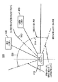
図1Aは一つのシステム100を示しており、そこでは、ここで説明する機能が採用されている。この例においては、3つの構成要素として、コントロール装置105、電子装置110、および、ディスプレイ120が在る。この形態においては、メディアプレーヤ110は、メディアプレーヤまたはパーソナルコンピュータなど、セットトップボックスであり、コントロール装置105およびディスプレイ120に接続されるように設計される。コントロール装置は、マウス、トラックボール、タッチパッド、またはジャイロスコープのリモコンなど、ポインターベースのコントロール装置である。コントロール装置105は、USBまたはネットワークケーブルなどの有線接続、または、赤外線(IR)、無線周波数(RF)、ブルートゥース(BT)、ワイヤレスネットワーキングプロトコル(WiFi)などのワイヤレス接続によって、電子装置110に接続される。ディスプレイ120は、陰極線管(CRT)、プラズマ、液晶ディスプレイ(LCD)、有機発光ダイオード(OLED)、および、同類のものなどのユーザーインターフェースを表示することができるディスプレイであれば、どんなディスプレイであってもよい。電子装置110とディスプレイ120の間の接続は、同軸、RCA、VGA、ディスプレイポート、DVI、HDMI(登録商標)、またはその他のタイプの接続であってもよい。
FIG. 1A shows one
図1Aの形態にあっては、コントロール装置105、電子装置110、および、ディスプレイ120が別個の装置として示されているものの、多くの形態において、これら装置のうちの一つまたはそれよりも多くを結合してもよい。このような例が、図1Bに見られる。図1Bは電子装置110を示しており、これはコントロール装置105とディスプレイ120を含んでいる。そのような電子装置の例は、限定はされないが、ラップトップ、パーソナルメディアプレーヤ、eブックリーダ、パーソナルゲームシステム、試験装置、および、同類のものを含む。
In the configuration of FIG. 1A, although
図2は、一実施形態に従った電子装置110の構成要素を示すブロック図である。この形態では、メディアプレーヤ110は、プロセッサ200、ストレージ210、入力インターフェース220、および、出力インターフェース230を備える。いくつかの形態では、この民生用電子装置は、さらに入力インターフェース240とネットワークインターフェース250を備えることができる。これら構成要素の各々について、以下でより詳細に説明される。
FIG. 2 is a block diagram illustrating components of the
プロセッサ200は電子装置110の動作を制御する。プロセッサ200がソフトウエアを実行し、該ソフトウエアがベクトルナビゲーションの機能を提供するだけでなく電子装置110を動作させる。プロセッサ200は、ストレージ210、入力インターフェース220、および、出力インターフェース230に接続され、いくつかの形態では、さらにネットワークインターフェース240に接続され、構成要素間における情報の転送および処理を扱う。プロセッサ200は一般的なプロセッサであっても、特定の機能に特化したプロセッサであってもよい。ある形態においては、複数のプロセッサが在ってよい。
The
ストレージ210は、電子装置110が使用するソフトウエアおよび他の情報をストアするところである。ストレージ210は、揮発性メモリ(RAM)、非揮発性メモリ(EEPROM)、磁気媒体(ハードドライブ)、光学媒体(CD/DVD−Rom)、または、フラッシュベースストレージを含むことができる。ある特定の形態において、ストレージ210は一般的に、メモリもハードドライブなどの大容量ストレージも含む。
入力インターフェース220が、ユーザーに電子装置110とのやりとりを可能にする。入力インターフェース220は、情報を入力するために用いられる、コントロール装置105などの様々な装置とインターフェースすることを取り扱う。
An
出力インターフェース230は、正しいフォーマットのメディアがディスプレイ120に出力することを提供する。適正なフォーマットは、出力されるコンテンツのコーデック(Codec)も、外部ビデオディスプレイ装置または音声装置に、あるいは、いくつかの形態においてはオンボードディスプレイまたはスピーカに接続するために用いるコネクタータイプも含むことができる。出力インターフェース230はまた、開示のベクトルナビゲーション機能を用いてナビゲートされるグラフィックおよびメニューを提供することができる。
The
特定の他の形態においては、電子装置110は、図1Bに示したように、コントロール装置105とディスプレイ120を含むものであってよい。図2に示した例では、コントロール装置105が入力インターフェース220に接続され、および、ディスプレイ120が出力インターフェース230に接続される。
In certain other forms, the
特定の他の形態においては、電子装置110はまた、ネットワークインターフェース240を含む。ネットワークインターフェース240は、他の装置またはネットワークとの電子装置110の通信を取り扱う。好適なネットワークの例は、イーサネット(登録商標)、または、同軸上マルチメディア(MoCa:Multimedia over Coaxial)ネットワークを含む。好適なホームネットワークの地のタイプは、当業者が本明細書の開示を利用することで明らかになろう。
In certain other forms, the
図2に示された構成要素は例示的なものであることが理解できよう。電子装置110は構成要素をいくつでも含むことができ、特定の構成要素は、他の構成要素の機能の一部または全部を提供することができる。例えば、入力インターフェース220および出力インターフェース230の機能の多くをプロセッサ200によって、または、汎用または専用の複数のプロセッサによって実行することができる。同様に、ネットワーク接続は、出力インターフェース230からも入力インターフェース220からも別個に実施することができる。可能なその他の実装は、当業者が本明細書の開示を利用することで明らかになろう。
It will be appreciated that the components shown in FIG. 2 are exemplary. The
図3は、ベクトルナビゲーションを用いるユーザーインターフェースのナビゲーションのための方法を示すフロー図である。その最も根本にあっては、この方法は4つのステップを含む。最初のステップでは、ユーザーインターフェースの少なくとも1つの要素及び少なくとも1つの近隣の定位(orientation)をベクトル情報として表現する(ステップ310)。ユーザーインターフェースをナビゲートするための動き情報入力が、次に受け取られる(ステップ320)。この動き情報はベクトル情報に変換される(ステップ330)。最後に、受け取られた動き情報から変換されたベクトル情報が、上記少なくとも1つの要素及び少なくとも1つの近隣(neighbor)の上記定位を表現する上記ベクトル情報にマッピングされる。特定の形態では、この方法はさらに、ユーザーインターフェースを表示するステップ(ステップ305)、および、表示されたインターフェースを更新して、少なくとも1つの要素及び少なくとも1つの近隣の定位にマッピングされた、受け取られた動き情報を反映するステップ(ステップ350)を含む。これらステップのそれぞれについて、以下でより詳細に説明する。 FIG. 3 is a flow diagram illustrating a method for user interface navigation using vector navigation. At its most basic, this method includes four steps. In the first step, at least one element of the user interface and at least one neighboring orientation are represented as vector information (step 310). Motion information input for navigating the user interface is then received (step 320). This motion information is converted into vector information (step 330). Finally, vector information transformed from the received motion information is mapped to the vector information representing the localization of the at least one element and at least one neighbor. In a particular form, the method further includes displaying a user interface (step 305) and updating the displayed interface to be mapped to at least one element and at least one neighboring location. The step of reflecting the motion information (step 350). Each of these steps is described in more detail below.
ユーザーインターフェースを表示すること(ステップ305)は、プロセッサ200がユーザーインターフェースを生成すること、そのユーザーインターフェースを出力インターフェース230がディスプレイ120に出力し、そのユーザーインターフェースを表示することを包含する。一実施形態では、ディレクションパッド(D−Pad)を直交(上/下/左/右)で用いてナビゲートする設計のグラフィカルユーザーインターフェースである。そのようなユーザーインターフェースの例は、限定はされないが、電子プログラムガイド(EPG)、設定および構成メニュー、オンスクリーンキーボード、および、同類のものを含む。このようなインターフェースにあっては、アクティブな要素が通常ハイライトされて、その要素のアクティブステータスを示し、および、ユーザーにユーザーインターフェースのナビゲーションのための基準位置を与える。伝統的には、ユーザーはD−Padを使用して、アクティブな要素を変更するための上/下/左/右命令の入力を、以前のアクティブな要素の上、下、左、または右の近隣の要素に与える。本明細書で開示する方法および教示によって、D−Padの代わりにポインターベースのコントロール装置を用いたこのようなタイプのユーザーインターフェースを、オンスクリーンインジケータを必要とすることなく、代わりに上述したハイライトされたアクティブ要素のインジケータを使用して、ユーザーがナビゲートできるようになる。
Displaying the user interface (step 305) includes the
このことを達成するためにベクトルナビゲーションが用いられる。ベクトルナビゲーションで、インターフェース中の要素及びそれらの近隣の定位がベクトル情報として表現される(ステップ310)。この一例が図4に見られる。 Vector navigation is used to accomplish this. In vector navigation, elements in the interface and their localization are represented as vector information (step 310). An example of this can be seen in FIG.
図4は、要素410及びその近隣420の定位を表現するために用いられるベクトル情報のグラフィック表現400である。この例では、ユーザーインターフェース410が、ユーザーインターフェースにおけるアクティブな要素である。アクティブな要素410とその近隣の要素の定位および関係を表現し、規定し、さもなければ説明するベクトル情報400は、向き(Φ)430コンポーネントと大きさ440コンポーネントを含む。同じようにして、その他の近隣の定位および関係を、ベクトル情報によって表現し、規定し、さもなければ説明することができる。この例が図5に見られる。
FIG. 4 is a
図5は、要素410及び複数の近隣420,430の定位を表現するために用いられるベクトル情報のグラフィック表現500である。複数の近隣420,430間の区別および選択における、システムのロバスト性を高めるために、受け容れ角度(acceptance angle)510,520が用いられる。受け容れ角度510,520は、特定の近隣を選択または変更するアクセプタプルコマンドのための“ウインドウ”を備えている。例えば、図5中には、2つの近隣420,430がある。一点鎖線(−・−)530は、近隣420,430を二等分する角度を描いている。線530より下の弧510は近隣420のための受け容れ角度を示し、線530より上の弧520は近隣430のための受け容れ角度を示す。図5の例では、受け容れ角度510,520は二等分角530から45°に設定されている。よって、受け取ったコマンドが、弧510で示される45°の受け容れ角度に含まれる向きを含むベクトル情報を有している場合、そのときは、近隣420が選択され新たなアクティブな要素とされる。しかし、受け取ったコマンドが、弧520で示される45°の受け容れ角度に含まれる向きを含むベクトル情報を有している場合、そのときは、近隣430が選択され新たなアクティブな要素とされる。
FIG. 5 is a
要素およびそれらの近隣の定位をユーザーインターフェースのためにベクトル情報でどのように表現できるかのさらなる例が、図6および図7に見られる。 A further example of how the localization of elements and their neighbors can be represented with vector information for the user interface can be seen in FIGS.
図6では、メニュー画面に要素を配列するとおりに、ユーザーインターフェース600の周辺部に要素が位置している。この例では、要素610aがハイライトされて、それがアクティブな要素であることを示している。各要素610a−610nの上へ重ね合わせたのは、矢印(→)で示される他の近隣要素に対する点線(・・・)および破線(−−−)で示される受け容れ角度のベクトルの関連(vector relationships)620a−620nの描写である。
In FIG. 6, the elements are located in the periphery of the
図7では、ユーザーインターフェース700におけるオンスクリーンキーボード内に要素が位置している。この例では、“T”のキーを表す要素がハイライトされて、それがアクティブな要素であることを示している。各要素(キー)の上へ重ね合わせたのは、点線(・・・)および破線(−−−)で示される他の近隣要素(キー)に対するベクトルの関連の描写である。
In FIG. 7, the element is located in the on-screen keyboard in the
同じ様にして、大きさ閾値情報(図示せず)を用いることもできる。すなわち、ベクトル情報の大きさコンポーネントについて閾値の値が設定される。この値は、特定の近隣を選択するために満たされなければならない最小の(または最大の、または両方の)値である。これにより、意図しない、偶然の、偶発的な、または不注意の、ポインターベースのコントロール装置が提供する入力によって引き起こされる、近隣の選択を除去する。またこれにより、同一のベクトル向きに沿った定位および位置を持った複数の近隣間での選択を、アクティブな要素と区別できる。 Similarly, size threshold information (not shown) can be used. That is, a threshold value is set for the magnitude component of the vector information. This value is the minimum (or maximum or both) value that must be met in order to select a particular neighbor. This eliminates neighborhood selection caused by unintended, accidental, accidental, or inadvertent input provided by a pointer-based control device. This also allows selection between multiple neighbors with localization and position along the same vector orientation to be distinguished from active elements.
図3に戻って、ユーザーインターフェースをナビゲートするための動き情報入力が受け取られ(ステップ320)、そして、図4に関連して上述したとおりに向きコンポーネント及び大きさコンポーネントを含むベクトル情報に変換される(ステップ330)。図1A,1B,および2に関連して上述したとおりに、コントロール装置から動き情報が受け取られる。一実施形態によれば、コントロール装置は、マウス、タッチパッド、トラックボールなど、ポインターベースのコントロール装置である。伝統的に、そのようなポインターベースのコントロール装置は垂直および水平の動き情報(例えば、方向、距離、および、速度)を提供し、該情報は画面上でのポインターの動きに変換される。本明細書に開示された技術を使用して、上述の公知の技術を使用するのと同様に、この動き情報はベクトル情報(向きおよび大きさ)に変換される。 Returning to FIG. 3, motion information input for navigating the user interface is received (step 320) and converted to vector information including orientation and magnitude components as described above in connection with FIG. (Step 330). Motion information is received from the control device as described above in connection with FIGS. 1A, 1B, and 2. According to one embodiment, the control device is a pointer-based control device such as a mouse, touchpad, trackball or the like. Traditionally, such pointer-based controls provide vertical and horizontal motion information (eg, direction, distance, and speed) that is converted into pointer motion on the screen. Using the techniques disclosed herein, this motion information is converted into vector information (orientation and magnitude), similar to using the known techniques described above.
動き情報入力がいったんベクトル情報に変換されると、アクティブな要素およびその近隣の定位を表現するベクトル情報にマッピングされる(ステップ340)。この一例が図8に見られる。 Once the motion information input is converted to vector information, it is mapped to vector information representing the active element and its localization (step 340). An example of this can be seen in FIG.
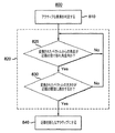
図8は、変換されたベクトル情報を、アクティブな要素およびその近隣の定位を表現するベクトル情報にマッピングする一実施形態のフローチャート800を示す。最初のステップで、アクティブな要素を判定する(ステップ810)。変換されたベクトル情報は次いで、そのアクティブな要素の一つまたはそれよりも多い近隣の定位を表現するベクトル情報と比較される(ステップ820)。近隣について基準が満たされた場合、次いでその近隣が新たなアクティブな要素とされる(ステップ840)。これにステップについて、以下で詳述する。
FIG. 8 shows a
アクティブな要素を判定する際に(ステップ810)、他の要素へナビゲートするための基準点が確立される。例えば、図5−7において、各要素は、その近隣に対するその定位/関係を規定する、関連するベクトル情報を有している。したがって、どの要素を動かすべきかを知るためには、動かされている要素が解らなければならない。 In determining an active element (step 810), a reference point is established for navigating to other elements. For example, in FIGS. 5-7, each element has associated vector information that defines its localization / relationship with respect to its neighbors. Therefore, in order to know which element should be moved, the element being moved must be understood.
アクティブな要素がいったん確立されると(ステップ810)、変換されたベクトル情報を、そのアクティブな要素およびその近隣の定位を表現するベクトル情報と比較することができ(ステップ820)。図8の例において、これは、変換されたベクトル情報の向きが近隣の受け容れ角度内にあるかどうかを判定すること(ステップ825)、および、変換されたベクトルの大きさが近隣の大きさの閾値に適合するかどうかを判定すること(ステップ830)を包含する。特定の形態にあっては、複数の近隣について、近隣が基準を満たすことが見出されるまでこの処理を繰り返し実施することができる。 Once an active element is established (step 810), the transformed vector information can be compared with vector information representing the active element and its localization (step 820). In the example of FIG. 8, this determines whether the orientation of the transformed vector information is within the neighborhood acceptance angle (step 825), and the magnitude of the transformed vector is the neighborhood magnitude. (Step 830). In certain forms, this process can be repeated for multiple neighbors until the neighbor is found to meet the criteria.
近隣についてベクトル情報の基準が満たされた場合は、その近隣が新たなアクティブな要素とされる(ステップ840)。これは表示されるユーザーインターフェースに反映され、そのアクティブな要素がハイライトされ、さもなければ指し示される(図3、ステップ350)。この処理は次いで、すべての、受け取った新しい動きコマンドについて繰り返すことができる。これがどのように動作するかの一例が図9に見られる。 If the vector information criterion for the neighborhood is met, the neighborhood is made a new active element (step 840). This is reflected in the displayed user interface, where the active element is highlighted and otherwise pointed (FIG. 3, step 350). This process can then be repeated for all new motion commands received. An example of how this works can be seen in FIG.
図9は、要素910および複数の近隣920,930,940,950の定位を表現するために用いられるベクトル情報のグラフィカル表現900である。この例では,角度コンポーネントだけを評価し、受け取った動きコマンドの変換されたベクトル情報の大きさが閾値要件を満たしていると仮定している。ここで、変換されたベクトル情報の向きの値が受け容れ角度”b”の範囲970内にある場合は、要素”E”950が新たなアクティブな要素へとナビゲートされ新たなアクティブな要素となる。変換されたベクトル情報の向きの値が受け容れ角度”a”の範囲960内にある場合は、要素”C”930が新たなアクティブな要素へとナビゲートされ新たなアクティブな要素となる。変換されたベクトル情報の向きの値が受け容れ角度”c”の範囲980内にある場合は、要素”B”920が新たなアクティブな要素へとナビゲートされ新たなアクティブな要素となる。変換されたベクトル情報の向きの値が受け容れ角度”d”の範囲990内にある場合は、どの要素もナビゲートされることなく、要素”A”が新たなアクティブな要素として維持される。変換されたベクトル情報の向きの値が受け容れ角度”e”の範囲1000内にある場合は、要素”D”940が新たなアクティブな要素へとナビゲートされ新たなアクティブな要素となる。
FIG. 9 is a
上では専ら電子装置の例について説明したが、本明細書で説明した方法の実装を可能にする全ての機能を持ったコンピュータプログラムであって、コンピュータシステムにロードしてこれら方法を実行することを可能にするコンピュータプログラムについて本発明を実施できることが理解できよう。この文脈におけるコンピュータプログラムすなわちアプリケーションは、情報処理能力を有するシステムに特定の機能を直接でも、a)他の言語、コード、または表記法に変換した後にでも、b)異なった材料における変換の後にでも、または双方の後にでも実行させることを意図した命令のセットの、どのような言語、コード、または表記法における、どのような表現をも意味している。 In the above, examples of electronic devices have been described exclusively. However, a computer program having all the functions enabling the implementation of the method described in the present specification, which is loaded into a computer system and executes these methods. It will be appreciated that the invention can be practiced with computer programs that enable it. A computer program or application in this context can either function directly on a system with information processing capabilities, either a) after conversion to another language, code or notation, or b) after conversion in a different material Means any representation in any language, code, or notation of a set of instructions intended to be executed after or both.
さらに、上での説明は単なる例としてしたものであり、本発明を、特許請求の範囲は別として、どのようなかたちであっても限定することを意図したものではない。 Furthermore, the above description is by way of example only and is not intended to limit the invention in any way, apart from the claims.
Claims (14)
前記ユーザーインターフェースの少なくとも1つの要素及び少なくとも1つの近隣の定位をベクトル情報として表現するステップ、
前記ユーザーインターフェースをナビゲートするための動き情報の入力を受け取るステップ、
前記動き情報をベクトル情報に変換するステップ、及び、
受け取った前記動き情報からの該ベクトル情報を、前記少なくとも1つの要素及び前記少なくとも1つの近隣の前記定位を表現する前記ベクトル情報にマッピングするステップ
を含む方法。 In a method for navigating a user interface:
Expressing at least one element of the user interface and at least one localization location as vector information;
Receiving input of motion information for navigating the user interface;
Converting the motion information into vector information; and
Mapping the vector information from the received motion information to the vector information representing the localization of the at least one element and the at least one neighbor.
前記ユーザーインターフェース中のアクティブな要素を判定すること、
前記変換されたベクトル情報の向きコンポーネントが、前記アクティブな要素及び少なくとも1つの近隣の定位を表現する前記ベクトル情報の受け容れ角度の範囲にあるかどうかを判定すること、
前記変換されたベクトル情報の大きさコンポーネントが、前記アクティブな要素及び少なくとも1つの近隣の定位を表現する前記ベクトル情報の大きさ閾値に適合するかどうかを判定すること、
前記変換されたベクトル情報の前記向き及び大きさコンポーネントが前記受け容れ角度内且つ前記大きさ閾値内である場合に、前記近隣を新しいアクティブな要素とすること
を含む、請求項1の方法。 Mapping the vector information from the received motion information to the vector information representing the localization of the at least one element and the at least one neighbor;
Determining active elements in the user interface;
Determining whether the orientation component of the transformed vector information is within a range of acceptance angles of the vector information representing the active element and at least one neighboring localization;
Determining whether the magnitude component of the transformed vector information meets a magnitude threshold of the vector information representing the active element and at least one neighboring localization;
The method of claim 1, comprising making the neighborhood a new active element if the orientation and magnitude components of the transformed vector information are within the acceptance angle and within the magnitude threshold.
ユーザーインターフェースを出力するように構成された出力インターフェース、
前記ユーザーインターフェースをナビゲートするための動き情報を受け取るように構成された入力インターフェース、
前記ユーザーインターフェースの少なくとも1つの要素及びその近隣の定位をベクトル情報として表現し、受け取った前記動き情報をベクトル情報に変換し、そして、受け取った前記動き情報からの該ベクトル情報を、前記少なくとも1つの要素及び前記少なくとも1つの近隣の前記定位を表現する前記ベクトル情報にマッピングするように構成されたプロセッサ、並びに、
前記ベクトル情報をストアするように構成されたストレージ
を備えるシステム。 In a system with an electronic device that allows navigation of the user interface,
An output interface configured to output a user interface,
An input interface configured to receive movement information for navigating the user interface;
Expressing at least one element of the user interface and its localization as vector information, converting the received motion information into vector information, and converting the received vector information from the received motion information into the at least one A processor configured to map to the vector information representing an element and the localization of the at least one neighbor; and
A system comprising a storage configured to store the vector information.
前記ユーザーインターフェースの少なくとも1つの要素及びその近隣の定位をベクトル情報として表現するステップ、
前記ユーザーインターフェースをナビゲートするための動き情報の入力を受け取るステップ、
前記動き情報をベクトル情報に変換するステップ、及び、
受け取った前記動き情報からの該ベクトル情報を、前記少なくとも1つの要素及び前記少なくとも1つの近隣の前記定位を表現する前記ベクトル情報にマッピングするステップ
を含むコンピュータプログラム。 A computer program including a computer usable medium, wherein the medium has a computer readable program and causes the computer to execute a method when the readable program is executed by the computer. Wherein the method comprises:
Expressing at least one element of the user interface and its localization as vector information;
Receiving input of motion information for navigating the user interface;
Converting the motion information into vector information; and
A computer program comprising the step of mapping the vector information from the received motion information to the vector information representing the localization of the at least one element and the at least one neighbor.
Applications Claiming Priority (3)
| Application Number | Priority Date | Filing Date | Title |
|---|---|---|---|
| US38897510P | 2010-10-01 | 2010-10-01 | |
| US61/388,975 | 2010-10-01 | ||
| PCT/US2011/054115 WO2012044877A1 (en) | 2010-10-01 | 2011-09-30 | System and method for navigation in a user interfface |
Related Child Applications (1)
| Application Number | Title | Priority Date | Filing Date |
|---|---|---|---|
| JP2016199253A Division JP2017079058A (en) | 2010-10-01 | 2016-10-07 | System and method for navigation in user interface |
Publications (2)
| Publication Number | Publication Date |
|---|---|
| JP2013539140A true JP2013539140A (en) | 2013-10-17 |
| JP2013539140A5 JP2013539140A5 (en) | 2014-11-20 |
Family
ID=45893528
Family Applications (2)
| Application Number | Title | Priority Date | Filing Date |
|---|---|---|---|
| JP2013531895A Pending JP2013539140A (en) | 2010-10-01 | 2011-09-30 | System and method for navigation in a user interface |
| JP2016199253A Pending JP2017079058A (en) | 2010-10-01 | 2016-10-07 | System and method for navigation in user interface |
Family Applications After (1)
| Application Number | Title | Priority Date | Filing Date |
|---|---|---|---|
| JP2016199253A Pending JP2017079058A (en) | 2010-10-01 | 2016-10-07 | System and method for navigation in user interface |
Country Status (6)
| Country | Link |
|---|---|
| US (1) | US10705625B2 (en) |
| EP (1) | EP2622451B1 (en) |
| JP (2) | JP2013539140A (en) |
| KR (1) | KR20130124502A (en) |
| CN (1) | CN103180811A (en) |
| WO (1) | WO2012044877A1 (en) |
Cited By (1)
| Publication number | Priority date | Publication date | Assignee | Title |
|---|---|---|---|---|
| JP2016155815A (en) * | 2011-01-11 | 2016-09-01 | スノビオン プハルマセウトイカルス インコーポレイテッド | Heteroaryl compound and method for using the same |
Families Citing this family (5)
| Publication number | Priority date | Publication date | Assignee | Title |
|---|---|---|---|---|
| US20130067366A1 (en) * | 2011-09-14 | 2013-03-14 | Microsoft Corporation | Establishing content navigation direction based on directional user gestures |
| CN103345248B (en) * | 2013-06-28 | 2015-12-09 | 深圳市江波龙电子有限公司 | A kind of control method of two-way movement equipment, Apparatus and system |
| US10089000B2 (en) | 2016-06-03 | 2018-10-02 | Microsoft Technology Licensing, Llc | Auto targeting assistance for input devices |
| CN108093283A (en) * | 2017-12-29 | 2018-05-29 | 王小艳 | A kind of implementation method of set-top box 3D rollings graphical interfaces |
| CN109091454B (en) * | 2018-08-24 | 2021-01-01 | 四川志邦生物科技有限公司 | Preparation method of closantel sodium injection |
Citations (5)
| Publication number | Priority date | Publication date | Assignee | Title |
|---|---|---|---|---|
| JP2003510926A (en) * | 1999-09-27 | 2003-03-18 | コーニンクレッカ フィリップス エレクトロニクス エヌ ヴィ | Directional navigation within the graphical user interface |
| US20040119744A1 (en) * | 2001-12-19 | 2004-06-24 | Sammy Chan | Selecting moving objects on a system |
| WO2009128148A1 (en) * | 2008-04-16 | 2009-10-22 | パイオニア株式会社 | Remote control device |
| US20100023862A1 (en) * | 2008-07-24 | 2010-01-28 | Xiaorong Tai | User Navigation via Vectors Dynamically Mapped to Distinct Media Attributes |
| JP2011054049A (en) * | 2009-09-03 | 2011-03-17 | Sony Corp | Information processing apparatus, information processing method, program, and information processing system |
Family Cites Families (16)
| Publication number | Priority date | Publication date | Assignee | Title |
|---|---|---|---|---|
| JPH05298023A (en) | 1992-04-20 | 1993-11-12 | Matsushita Electric Ind Co Ltd | Icon selecting method |
| JPH08314637A (en) | 1995-05-22 | 1996-11-29 | Matsushita Electric Ind Co Ltd | Video display device |
| KR100327209B1 (en) * | 1998-05-12 | 2002-04-17 | 윤종용 | Software keyboard system using the drawing of stylus and method for recognizing keycode therefor |
| ITRM20010032A1 (en) * | 2001-01-24 | 2002-07-24 | Fabrizio Giacomelli | METHOD OF MOVING A GRAPHIC POINTER ON A WORK AREA OF A SCREEN OF A PROCESSOR. |
| US20030106057A1 (en) | 2001-12-05 | 2003-06-05 | Predictive Networks, Inc. | Television navigation program guide |
| US8566751B2 (en) | 2005-01-24 | 2013-10-22 | International Business Machines Corporation | GUI pointer automatic position vectoring |
| US7616191B2 (en) * | 2005-04-18 | 2009-11-10 | Avago Technologies Ecbu Ip (Singapore) Pte. Ltd. | Electronic device and method for simplifying text entry using a soft keyboard |
| US20070061749A1 (en) * | 2005-08-29 | 2007-03-15 | Microsoft Corporation | Virtual focus for contextual discovery |
| TW200832205A (en) * | 2006-10-11 | 2008-08-01 | Koninkl Philips Electronics Nv | Method and a system for navigating between buttons displayed on a user interface |
| US20080104058A1 (en) * | 2006-11-01 | 2008-05-01 | United Video Properties, Inc. | Presenting media guidance search results based on relevancy |
| US20090037813A1 (en) | 2007-07-31 | 2009-02-05 | Palo Alto Research Center Incorporated | Space-constrained marking menus for mobile devices |
| KR101182286B1 (en) | 2007-09-19 | 2012-09-14 | 삼성전자주식회사 | Remote controller for sensing motion, image display apparatus controlling pointer by the remote controller, and methods thereof |
| US8615720B2 (en) * | 2007-11-28 | 2013-12-24 | Blackberry Limited | Handheld electronic device and associated method employing a graphical user interface to output on a display virtually stacked groups of selectable objects |
| JP5219152B2 (en) | 2008-04-21 | 2013-06-26 | 株式会社ワコム | Operation input device, radial menu used in operation input device, method for setting variable value using radial control menu, and computer system |
| US8531461B2 (en) * | 2009-09-29 | 2013-09-10 | Blackberry Limited | Portable electronic device and method of controlling same |
| JP2011154543A (en) | 2010-01-27 | 2011-08-11 | Kyocera Corp | Electronic equipment, input method, and input program |
-
2011
- 2011-09-30 EP EP11829939.5A patent/EP2622451B1/en active Active
- 2011-09-30 WO PCT/US2011/054115 patent/WO2012044877A1/en active Application Filing
- 2011-09-30 CN CN2011800477852A patent/CN103180811A/en active Pending
- 2011-09-30 KR KR1020137011292A patent/KR20130124502A/en not_active Application Discontinuation
- 2011-09-30 US US13/876,377 patent/US10705625B2/en active Active
- 2011-09-30 JP JP2013531895A patent/JP2013539140A/en active Pending
-
2016
- 2016-10-07 JP JP2016199253A patent/JP2017079058A/en active Pending
Patent Citations (5)
| Publication number | Priority date | Publication date | Assignee | Title |
|---|---|---|---|---|
| JP2003510926A (en) * | 1999-09-27 | 2003-03-18 | コーニンクレッカ フィリップス エレクトロニクス エヌ ヴィ | Directional navigation within the graphical user interface |
| US20040119744A1 (en) * | 2001-12-19 | 2004-06-24 | Sammy Chan | Selecting moving objects on a system |
| WO2009128148A1 (en) * | 2008-04-16 | 2009-10-22 | パイオニア株式会社 | Remote control device |
| US20100023862A1 (en) * | 2008-07-24 | 2010-01-28 | Xiaorong Tai | User Navigation via Vectors Dynamically Mapped to Distinct Media Attributes |
| JP2011054049A (en) * | 2009-09-03 | 2011-03-17 | Sony Corp | Information processing apparatus, information processing method, program, and information processing system |
Cited By (1)
| Publication number | Priority date | Publication date | Assignee | Title |
|---|---|---|---|---|
| JP2016155815A (en) * | 2011-01-11 | 2016-09-01 | スノビオン プハルマセウトイカルス インコーポレイテッド | Heteroaryl compound and method for using the same |
Also Published As
| Publication number | Publication date |
|---|---|
| US10705625B2 (en) | 2020-07-07 |
| EP2622451A1 (en) | 2013-08-07 |
| EP2622451A4 (en) | 2016-08-31 |
| US20130191788A1 (en) | 2013-07-25 |
| KR20130124502A (en) | 2013-11-14 |
| CN103180811A (en) | 2013-06-26 |
| JP2017079058A (en) | 2017-04-27 |
| WO2012044877A1 (en) | 2012-04-05 |
| EP2622451B1 (en) | 2021-06-09 |
Similar Documents
| Publication | Publication Date | Title |
|---|---|---|
| JP2017079058A (en) | System and method for navigation in user interface | |
| US11687214B2 (en) | Method and apparatus for changing screen in electronic device | |
| US9223416B2 (en) | Display apparatus, remote controlling apparatus and control method thereof | |
| US10948950B2 (en) | Information processing device, table, display control method, program, portable terminal, and information processing system | |
| US9100614B2 (en) | Graphical interface navigation based on image element proximity | |
| KR101463540B1 (en) | Method for controlling three dimensional virtual cursor using portable device | |
| US20110202838A1 (en) | Apparatus and method for providing user interface | |
| US20130342456A1 (en) | Remote control apparatus and control method thereof | |
| US9588677B2 (en) | Systems and methods for touch-screen-based remote interaction with a graphical user interface | |
| US20130198690A1 (en) | Visual indication of graphical user interface relationship | |
| CN108024127A (en) | Image display device, mobile equipment and its operating method | |
| US20210181939A1 (en) | Display device and operating method thereof | |
| KR101339985B1 (en) | Display apparatus, remote controlling apparatus and control method thereof | |
| US20090251609A1 (en) | System and method for determining a mode of viewing a display and adapting displayed elements to the mode of viewing | |
| EP3056974A2 (en) | Display apparatus and method | |
| US10719147B2 (en) | Display apparatus and control method thereof | |
| US11914803B2 (en) | Electronic device for controlling external electronic devices using relative position information and operating method thereof | |
| WO2024060890A1 (en) | Information prompting method and apparatus for virtual terminal device, device, medium, and product | |
| KR20130092244A (en) | Method and apparatus for converting relative coordinate received wirelessly to input value to application |
Legal Events
| Date | Code | Title | Description |
|---|---|---|---|
| A521 | Written amendment |
Free format text: JAPANESE INTERMEDIATE CODE: A523 Effective date: 20140930 |
|
| A621 | Written request for application examination |
Free format text: JAPANESE INTERMEDIATE CODE: A621 Effective date: 20140930 |
|
| A131 | Notification of reasons for refusal |
Free format text: JAPANESE INTERMEDIATE CODE: A131 Effective date: 20151013 |
|
| A977 | Report on retrieval |
Free format text: JAPANESE INTERMEDIATE CODE: A971007 Effective date: 20151014 |
|
| A521 | Written amendment |
Free format text: JAPANESE INTERMEDIATE CODE: A523 Effective date: 20160112 |
|
| A02 | Decision of refusal |
Free format text: JAPANESE INTERMEDIATE CODE: A02 Effective date: 20160607 |