JP2013509914A - Multi-layer filamentary device or vascular treatment - Google Patents
Multi-layer filamentary device or vascular treatment Download PDFInfo
- Publication number
- JP2013509914A JP2013509914A JP2012537226A JP2012537226A JP2013509914A JP 2013509914 A JP2013509914 A JP 2013509914A JP 2012537226 A JP2012537226 A JP 2012537226A JP 2012537226 A JP2012537226 A JP 2012537226A JP 2013509914 A JP2013509914 A JP 2013509914A
- Authority
- JP
- Japan
- Prior art keywords
- shell
- filaments
- filament
- state
- permeable shell
- Prior art date
- Legal status (The legal status is an assumption and is not a legal conclusion. Google has not performed a legal analysis and makes no representation as to the accuracy of the status listed.)
- Pending
Links
Images


Classifications
-
- A—HUMAN NECESSITIES
- A61—MEDICAL OR VETERINARY SCIENCE; HYGIENE
- A61B—DIAGNOSIS; SURGERY; IDENTIFICATION
- A61B17/00—Surgical instruments, devices or methods, e.g. tourniquets
- A61B17/12—Surgical instruments, devices or methods, e.g. tourniquets for ligaturing or otherwise compressing tubular parts of the body, e.g. blood vessels, umbilical cord
- A61B17/12022—Occluding by internal devices, e.g. balloons or releasable wires
- A61B17/12099—Occluding by internal devices, e.g. balloons or releasable wires characterised by the location of the occluder
- A61B17/12109—Occluding by internal devices, e.g. balloons or releasable wires characterised by the location of the occluder in a blood vessel
- A61B17/12113—Occluding by internal devices, e.g. balloons or releasable wires characterised by the location of the occluder in a blood vessel within an aneurysm
-
- A—HUMAN NECESSITIES
- A61—MEDICAL OR VETERINARY SCIENCE; HYGIENE
- A61B—DIAGNOSIS; SURGERY; IDENTIFICATION
- A61B17/00—Surgical instruments, devices or methods, e.g. tourniquets
- A61B17/12—Surgical instruments, devices or methods, e.g. tourniquets for ligaturing or otherwise compressing tubular parts of the body, e.g. blood vessels, umbilical cord
- A61B17/12022—Occluding by internal devices, e.g. balloons or releasable wires
- A61B17/12099—Occluding by internal devices, e.g. balloons or releasable wires characterised by the location of the occluder
- A61B17/12109—Occluding by internal devices, e.g. balloons or releasable wires characterised by the location of the occluder in a blood vessel
- A61B17/12113—Occluding by internal devices, e.g. balloons or releasable wires characterised by the location of the occluder in a blood vessel within an aneurysm
- A61B17/12118—Occluding by internal devices, e.g. balloons or releasable wires characterised by the location of the occluder in a blood vessel within an aneurysm for positioning in conjunction with a stent
-
- A—HUMAN NECESSITIES
- A61—MEDICAL OR VETERINARY SCIENCE; HYGIENE
- A61B—DIAGNOSIS; SURGERY; IDENTIFICATION
- A61B17/00—Surgical instruments, devices or methods, e.g. tourniquets
- A61B17/12—Surgical instruments, devices or methods, e.g. tourniquets for ligaturing or otherwise compressing tubular parts of the body, e.g. blood vessels, umbilical cord
- A61B17/12022—Occluding by internal devices, e.g. balloons or releasable wires
- A61B17/12131—Occluding by internal devices, e.g. balloons or releasable wires characterised by the type of occluding device
- A61B17/12168—Occluding by internal devices, e.g. balloons or releasable wires characterised by the type of occluding device having a mesh structure
- A61B17/12172—Occluding by internal devices, e.g. balloons or releasable wires characterised by the type of occluding device having a mesh structure having a pre-set deployed three-dimensional shape
-
- A—HUMAN NECESSITIES
- A61—MEDICAL OR VETERINARY SCIENCE; HYGIENE
- A61B—DIAGNOSIS; SURGERY; IDENTIFICATION
- A61B17/00—Surgical instruments, devices or methods, e.g. tourniquets
- A61B17/12—Surgical instruments, devices or methods, e.g. tourniquets for ligaturing or otherwise compressing tubular parts of the body, e.g. blood vessels, umbilical cord
- A61B17/12022—Occluding by internal devices, e.g. balloons or releasable wires
- A61B17/12131—Occluding by internal devices, e.g. balloons or releasable wires characterised by the type of occluding device
- A61B17/12168—Occluding by internal devices, e.g. balloons or releasable wires characterised by the type of occluding device having a mesh structure
- A61B17/12177—Occluding by internal devices, e.g. balloons or releasable wires characterised by the type of occluding device having a mesh structure comprising additional materials, e.g. thrombogenic, having filaments, having fibers or being coated
-
- A—HUMAN NECESSITIES
- A61—MEDICAL OR VETERINARY SCIENCE; HYGIENE
- A61B—DIAGNOSIS; SURGERY; IDENTIFICATION
- A61B17/00—Surgical instruments, devices or methods, e.g. tourniquets
- A61B2017/00526—Methods of manufacturing
-
- A—HUMAN NECESSITIES
- A61—MEDICAL OR VETERINARY SCIENCE; HYGIENE
- A61B—DIAGNOSIS; SURGERY; IDENTIFICATION
- A61B17/00—Surgical instruments, devices or methods, e.g. tourniquets
- A61B17/12—Surgical instruments, devices or methods, e.g. tourniquets for ligaturing or otherwise compressing tubular parts of the body, e.g. blood vessels, umbilical cord
- A61B17/12022—Occluding by internal devices, e.g. balloons or releasable wires
- A61B2017/1205—Introduction devices
-
- A—HUMAN NECESSITIES
- A61—MEDICAL OR VETERINARY SCIENCE; HYGIENE
- A61B—DIAGNOSIS; SURGERY; IDENTIFICATION
- A61B17/00—Surgical instruments, devices or methods, e.g. tourniquets
- A61B17/22—Implements for squeezing-off ulcers or the like on the inside of inner organs of the body; Implements for scraping-out cavities of body organs, e.g. bones; Calculus removers; Calculus smashing apparatus; Apparatus for removing obstructions in blood vessels, not otherwise provided for
- A61B2017/22051—Implements for squeezing-off ulcers or the like on the inside of inner organs of the body; Implements for scraping-out cavities of body organs, e.g. bones; Calculus removers; Calculus smashing apparatus; Apparatus for removing obstructions in blood vessels, not otherwise provided for with an inflatable part, e.g. balloon, for positioning, blocking, or immobilisation
- A61B2017/22065—Functions of balloons
- A61B2017/22067—Blocking; Occlusion
Abstract
患者の脳血管系の処置のためのマイクロカテーテルで送達するために構成される、いくつかの実施形態による患者の血管系の処置のためのデバイスおよび方法。いくつかの実施形態は、それを通る血流を閉塞するように構成される、透過シェルおよび内部構造を含んでもよい。患者の血管系の処置のためのデバイスのいくつかの実施形態は、近位端、遠位端、および長手軸を有する自己拡張型弾力性透過シェルを含む。透過シェルはまた、その近位端および遠位端において相互に対して固定される織物構造を有する複数の細長い弾力性フィラメントを含む。Devices and methods for treatment of a patient's vasculature according to some embodiments, configured for delivery with a microcatheter for treatment of the patient's cerebral vasculature. Some embodiments may include a permeable shell and an internal structure configured to occlude blood flow therethrough. Some embodiments of a device for treatment of a patient's vasculature include a self-expanding resilient permeable shell having a proximal end, a distal end, and a longitudinal axis. The permeable shell also includes a plurality of elongated resilient filaments having a woven structure that is secured to each other at their proximal and distal ends.
Description
(関連出願の相互参照)
本願は、P.Marchandらによる米国仮特許出願第61/258,541号(名称「Multiple Layer Filamentary Devices for Treatment of Vascular Defects」、2009年11月5日出願、代理人整理番号SMI−0105−PV)、P.Marchandらによる米国仮特許出願第61/294,760号(名称「Multiple Layer Filamentary Devices for Treatment of Vascular Defects」、2010年1月13日出願、代理人整理番号SMI−0105−PV2)、およびP.Marchandらによる米国仮特許出願第61/334,130号(名称「Multiple Layer Filamentary Devices for Treatment of Vascular Defects」、2010年5月12日出願、代理人整理番号SMI−0105−PV3)の米国特許法第119条第(e)項の優先権の利益を主張し、これらの出願の各々は、その全体が本明細書に参照によって援用される。
(Cross-reference of related applications)
The present application refers to P.I. U.S. Provisional Patent Application No. 61 / 258,541 by Marchand et al. (Named “Multilayer Filamentary Devices for Treatment of Vascular Defects”, filed Nov. 5, 2009, agent serial number SMI-0105-PV). US Provisional Patent Application No. 61 / 294,760 by Marchand et al. (Named “Multilayer Filamentary Devices for Treatment of Vascular Defects”, filed Jan. 13, 2010, attorney docket number SMI-0105-PV2). United States Provisional Patent Application No. 61 / 334,130 by Marchand et al. (Named “Multilayer Filamentary Devices for Treatment of Vascular Defects”, filed May 12, 2010, attorney docket number SMI-0105-PV3) Claiming the benefit of priority in section 119 (e), each of these applications is hereby incorporated by reference in its entirety.
本願はまた、Coxらによる米国特許出願公開第12/602,997号(名称「Methods and Devices for Treatment of Vascular Defects」、2008年6月3日出願、代理人整理番号SMI−0103−US)、およびP.Marchandらによる米国特許出願公開第12/434,465号(名称「Filamentary Devices for Treatment of Vascular Defects」、2009年5月1日出願、代理人整理番号SMI−0104−UT)に関連し、これらの出願の各々は、その全体が本明細書に参照によって援用される。 This application also includes US Patent Application Publication No. 12 / 602,997 by Cox et al. (Named “Methods and Devices for Treatment of Vascular Defects”, filed Jun. 3, 2008, Attorney Docket No. SMI-0103-US), And P.M. Related to US Patent Application Publication No. 12 / 434,465 by Marchand et al. (Named “Flamenary Devices for Treatment of Vascular Defects”, filed May 1, 2009, Attorney Docket No. SMI-0104-UT). Each of the applications is incorporated herein by reference in its entirety.
(発明の分野)
本明細書のデバイスおよび方法の実施形態は、哺乳類の体内で、管状血管を通る、あるいは嚢状空洞または血管障害の小型内部チャンバの中への流体の流れの遮断を対象とする。より具体的には、本明細書の実施形態は、具体的には患者の脳動脈瘤の処置を対象とする、いくつかの実施形態を含む、患者の血管障害の処置のためのデバイスおよび方法を対象とする。
(Field of Invention)
Embodiments of the devices and methods herein are directed to blocking fluid flow within a mammalian body through a tubular vessel or into a sac cavity or small internal chamber of a vascular lesion. More specifically, embodiments herein are devices and methods for the treatment of vascular disorders in patients, including some embodiments, specifically directed to the treatment of cerebral aneurysms in patients. Is targeted.
哺乳類の循環系は、ポンプとして働く心臓、および体内の様々なポイントに血液を輸送する血管系から成る。血管上を流れる血液によって及ぼされる力により、血管は種々の血管障害を発症する場合がある。動脈瘤として知られる1つの一般的な血管障害は、血管の異常な拡大に起因する。典型的には、血管動脈瘤は、血管の壁が弱まり、続いて血管壁が膨張および拡張した結果として形成される。例えば、動脈瘤が脳の動脈内に存在し、動脈瘤は結果として脳出血を引き起こして破裂することとなった場合、死亡も起こり得る。 The mammalian circulatory system consists of a heart that acts as a pump and a vascular system that transports blood to various points in the body. Due to the force exerted by the blood flowing over the blood vessels, the blood vessels can develop various vascular disorders. One common vascular disorder known as an aneurysm is due to abnormal enlargement of blood vessels. Typically, a vascular aneurysm is formed as a result of a weakened vessel wall followed by dilation and dilation of the vessel wall. For example, if an aneurysm is present in an artery of the brain and the aneurysm results in cerebral hemorrhage and rupture, death can also occur.
脳動脈瘤の処置のための外科技術は、典型的には、それを通して外科医が患者の脳に直接手術する器具を挿入できる患者の頭蓋の開口部の作成を必要とする開頭術を伴う。いくつかの外科的アプローチについて、動脈瘤が生じる親血管を露出するように、脳を後退させなければならない。いったん動脈瘤へのアクセスが獲得されると、外科医は動脈瘤の頚部を横断してクリップを配置し、それによって動脈血が動脈瘤に進入するのを防止する。クリップを正しく配置すると、動脈瘤はほんの数分で抹消されるであろう。外科技術は、多くの動脈瘤にとって効果的な処置であってもよい。残念ながら、これらの種類の症状を処置するための外科技術は、患者に対して高い危険性を伴う麻酔下での長期間をしばしば必要とする、侵襲的な大手術手技を含む。したがって、かかる手技は、患者がかかる手技の候補者であるために、概して良い健康状態であることを要求する。 Surgical techniques for the treatment of cerebral aneurysms typically involve craniotomy that requires the creation of an opening in the patient's skull through which a surgeon can insert a surgical instrument directly into the patient's brain. For some surgical approaches, the brain must be retracted to expose the parent vessel where the aneurysm occurs. Once access to the aneurysm is gained, the surgeon places a clip across the neck of the aneurysm, thereby preventing arterial blood from entering the aneurysm. With the clip placed correctly, the aneurysm will be erased in a matter of minutes. Surgical techniques may be an effective procedure for many aneurysms. Unfortunately, surgical techniques for treating these types of symptoms include invasive major surgical procedures that often require a long period of time under anesthesia with high risk to the patient. Such procedures therefore require that the patient is generally in good health because the patient is a candidate for such procedures.
種々の代替的かつ低侵襲的手技が、大手術を用いることなく、脳動脈瘤を処置するために使用されている。いくつかのかかる手技は、動脈瘤の中への塞栓または充填材料の送達を伴う。かかる血管閉塞デバイスまたは材料の送達は、止血を促進するか、または完全に動脈瘤の空洞を充填するために使用されてもよい。血管閉塞デバイスは、塞栓の形成を通して動脈瘤を伴う血管を通る血流を遮断するように、または血管に由来する動脈瘤内にかかる塞栓を形成するように、典型的にはカテーテルを介して人体の血管系の中に配置されてもよい。種々の埋め込み可能なコイル型血管閉塞デバイスが知られている。かかるデバイスのコイルはそれ自体で、2次的コイル形状、または種々のより複雑な2次的形状のうちのいずれかへと形成されてもよい。血管閉塞コイルが、脳動脈瘤を処置するために一般的に使用されるが、充填密度の不足と、血流からの動圧による圧縮と、幅広の頚部を持つ動脈瘤における安定性の不足と、このアプローチによる大部分の動脈瘤処置が複数のコイルの配備を必要とするために、その配備の複雑性および困難とを含む、いくつかの制限に悩まされている。 A variety of alternative and minimally invasive procedures have been used to treat cerebral aneurysms without using major surgery. Some such procedures involve the delivery of emboli or filler material into the aneurysm. Delivery of such vaso-occlusive devices or materials may be used to promote hemostasis or completely fill the aneurysm cavity. A vaso-occlusive device is typically via a catheter to block blood flow through a blood vessel with an aneurysm through the formation of an embolus, or to form an embolus within an aneurysm derived from a blood vessel. May be placed in the vasculature. Various implantable coiled vaso-occlusive devices are known. The coil of such a device may itself be formed into either a secondary coil shape or a variety of more complex secondary shapes. Vaso-occlusive coils are commonly used to treat cerebral aneurysms, but lack of filling density, compression due to dynamic pressure from the bloodstream, and lack of stability in aneurysms with wide necks Because most aneurysm procedures with this approach require multiple coil deployments, they suffer from several limitations, including the complexity and difficulty of their deployment.
侵襲的手術を必要とせずに動脈瘤を処置することへの別のアプローチは、血管の中へ、および動脈瘤が発生する領域を横断した、スリーブまたはステントの配置を伴う。かかるデバイスは、動脈瘤の内部に加えられる血圧を減少させながら、血管を通る血流を維持する。ある種類のステントは、バルーン拡張式ステントと呼ばれるバルーンカテーテルを膨張させることによって、適切なサイズまで拡張される一方で、他のステントは、自己拡張様式で弾力性的に拡張するように設計されている。いくつかのステントは、典型的には、ステントグラフトを形成するグラフトと呼ばれる、ポリマー材料のスリーブで被覆される。ステントおよびステントグラフトは概して、送達カテーテルを通して、血管障害に隣接する事前に選択された位置まで送達される。脳動脈瘤の処置において、被覆されたステントまたはステントグラフトは、処置されている血管障害の付近にあり得る、小穿通枝血管を不注意に閉塞する可能性により、非常に限定的に使用されているようである。 Another approach to treating an aneurysm without the need for invasive surgery involves the placement of a sleeve or stent into the blood vessel and across the area where the aneurysm occurs. Such devices maintain blood flow through the blood vessels while reducing the blood pressure applied to the interior of the aneurysm. One type of stent is expanded to the appropriate size by inflating a balloon catheter called a balloon expandable stent, while other stents are designed to expand elastically in a self-expanding manner. Yes. Some stents are typically covered with a sleeve of polymeric material, called the graft that forms the stent graft. Stents and stent grafts are generally delivered through a delivery catheter to a preselected location adjacent to a vascular lesion. In the treatment of cerebral aneurysms, coated stents or stent-grafts are used very limitedly due to the possibility of inadvertently occluding small perforating vessels that may be in the vicinity of the vascular disorder being treated It seems.
加えて、現行の非被覆ステントは、概して、単独の処置としては十分ではない。ステントが小脳血管で使用されるマイクロカテーテルを通って嵌合するためには、拡張されるときに、動脈瘤頚部を架橋する少量のステント構造のみがあるように、それらの密度は普通低減される。したがって、それらは動脈瘤の中の血液の凝固を引き起こすのに十分な流れを遮断せず、したがって、動脈瘤閉塞を達成するために、概して、上述のコイル等の血管閉塞デバイスと組み合わせて使用される。 In addition, current uncoated stents are generally not sufficient as a single procedure. In order for stents to fit through microcatheters used in cerebellar blood vessels, their density is usually reduced so that there is only a small amount of stent structure that bridges the aneurysm neck when expanded. . Thus, they do not block sufficient flow to cause blood clotting in the aneurysm and are therefore generally used in combination with vascular occlusion devices such as the coils described above to achieve aneurysm occlusion. The
欠陥範囲部分または領域を伴う、動脈瘤頚部を架橋するいくつかのデバイスが試みられてきたが、これらのデバイスのうちのいずれも、有意な程度の臨床上の成功または使用法を有するに至っていない。これらの採用および臨床上の有用性における主要な制限は、頚部を確実に被覆するように、欠陥範囲部分を設置することができないことである。神経血管に適合する(すなわち、マイクロカテーテルを通して送達可能であり、高度に可撓性である)既存のステント送達システムには、必要な回転位置決め能力がない。従来技術で説明されている多くの動脈瘤架橋デバイスの別の制限は、可撓性の不足である。脳血管は蛇行しており、脳の中の大部分の動脈瘤の場所へ効果的に送達するには、高い可撓性が必要とされる。 Several devices have been attempted to bridge the aneurysm neck with a defective area or region, but none of these devices have had a significant degree of clinical success or usage . A major limitation in their adoption and clinical utility is the inability to place defect areas to reliably cover the neck. Existing stent delivery systems that are neurovascular compatible (ie, deliverable through a microcatheter and highly flexible) do not have the necessary rotational positioning capability. Another limitation of many aneurysm bridging devices described in the prior art is a lack of flexibility. The cerebral blood vessels are serpentine and high flexibility is required for effective delivery to most aneurysm locations in the brain.
必要とされているものは、脳動脈瘤等の動脈瘤の中への血液の流れを実質的に遮断することができる、小蛇行性血管内での送達および使用のためのデバイスならびに方法である。加えて、必要とされているものは、変形、圧縮、または転位の著しい危険性なしに、長期間に渡り脳動脈瘤の中で血流を遮断するのに好適な方法およびデバイスである。 What is needed is a device and method for delivery and use within a tortuous vessel that can substantially block blood flow into an aneurysm, such as a cerebral aneurysm . In addition, what is needed is a method and device suitable for blocking blood flow in a cerebral aneurysm for extended periods without significant risk of deformation, compression, or translocation.
患者の血管系の処置のためのデバイスのいくつかの実施形態は、近位端、遠位端、および長手軸を有する自己拡張型弾力性透過シェルを含む。透過シェルはまた、その近位端および遠位端において相互に対して固定される織物構造を有する複数の細長い弾力性フィラメントを含む。透過シェルは、フィラメントの長さに沿って、相互に半径方向に隣接して近位端から遠位端まで長手方向に延在する薄い織物フィラメントとともに、マイクロカテーテル内を送達するように構成される、半径方向に拘束された細長い状態を有する。透過シェルはまた、織物フィラメント間に形成されたシェルの中に複数の開口部を含む、近位端と遠位端との間の長手軸から半径方向に拡張される平滑経路の中で、自己拡張型弾力性透過シェルを形成する織物フィラメントを有する、長手方向に短縮された構成を有する、半径方向に拘束された状態に対して拡張された弛緩状態を有し、該開口部のうちの最大のものは、血栓臨界速度を下回る速度で、開口部を通る血流を可能にするように構成される。 したがって、透過シェル内の血流は、血栓形成速度以下まで実質的に減速されてもよい。いくつかの実施形態に対して、透過シェルは、拡張された弛緩状態で球形を有してもよい。いくつかの実施形態では、シェルは、実質的に平坦な端または丸い端を有する略円筒形を有してもよい。これらの実施形態のうちのいくつかはまた、弾力性透過シェル内に配置されるフィラメント状部材の内部構造を含んでもよい。特に明記しない限り、種々の実施形態の特徴、寸法、または材料のうちの1つ以上は、本明細書で論議される他の同様の実施形態で使用されてもよい。 Some embodiments of a device for treatment of a patient's vasculature include a self-expanding resilient permeable shell having a proximal end, a distal end, and a longitudinal axis. The permeable shell also includes a plurality of elongated resilient filaments having a woven structure that is secured to each other at their proximal and distal ends. The permeable shell is configured to deliver within the microcatheter with a thin woven filament extending radially adjacent to each other longitudinally from the proximal end to the distal end along the length of the filament. , Having an elongated state constrained in the radial direction. The permeable shell also includes a plurality of openings in the shell formed between the woven filaments, in a smooth path that is radially expanded from the longitudinal axis between the proximal and distal ends. Having a woven filament forming an expandable elastic permeable shell, having a longitudinally shortened configuration, having a relaxed state expanded relative to a radially constrained state, the largest of the openings Are configured to allow blood flow through the opening at a rate below the thrombus critical rate. Accordingly, blood flow within the permeable shell may be substantially slowed to below the thrombus formation rate. For some embodiments, the permeable shell may have a spherical shape in the expanded relaxed state. In some embodiments, the shell may have a generally cylindrical shape with a substantially flat end or a rounded end. Some of these embodiments may also include an internal structure of a filamentary member disposed within the resilient permeable shell. Unless otherwise stated, one or more of the features, dimensions, or materials of the various embodiments may be used in other similar embodiments discussed herein.
患者の血管系の処置のためのデバイスのいくつかの実施形態は、近位端、遠位端、および長手軸を有する、自己拡張型弾力性透過シェルを含む。透過シェルはまた、その近位端および遠位端で相互に対して固定される織物構造を有する、少なくとも2つの異なる横寸法の大型フィラメントおよび小型フィラメントを含む、複数の細長い弾力性フィラメントを含んでもよい。透過シェルはまた、フィラメントの長さに沿って、相互に半径方向に隣接して近位端から遠位端まで長手方向に延在する、薄い織物フィラメントとともに、マイクロカテーテル内での送達用に構成される、半径方向に拘束された細長い状態を含んでもよい。透過シェルはまた、織物フィラメント間に形成されたシェルの中に複数の開口部を含む、近位端と遠位端との間の長手軸から半径方向に拡張される平滑経路の中で、自己拡張型弾力性透過シェルを形成する織物フィラメントを有する、球状であり長手方向に短縮された構成を有する、半径方向に拘束された状態に対して拡張された弛緩状態を有する。 Some embodiments of a device for treatment of a patient's vasculature include a self-expanding resilient permeable shell having a proximal end, a distal end, and a longitudinal axis. The permeable shell may also include a plurality of elongated elastic filaments, including at least two different transverse dimension large and small filaments, having a woven structure secured to each other at its proximal and distal ends. Good. The permeable shell is also configured for delivery within a microcatheter with a thin woven filament extending longitudinally from the proximal end to the distal end adjacent to each other radially along the length of the filament. It may include a radially constrained elongated state. The permeable shell also includes a plurality of openings in the shell formed between the woven filaments, in a smooth path that is radially expanded from the longitudinal axis between the proximal and distal ends. It has a relaxed state, expanded to a radially constrained state, having a spherical, longitudinally shortened configuration with a woven filament forming an expandable elastic permeable shell.
これらの実施形態のうちのいくつかはまた、弾力性透過シェル内に配置されるフィラメント状部材の内部構造を含んでもよい。 Some of these embodiments may also include an internal structure of a filamentary member disposed within the resilient permeable shell.
患者の血管系の処置のためのデバイスのいくつかの実施形態は、近位端、遠位端、および長手軸を有する、自己拡張型弾力性透過シェルを含む。透過シェルはまた、その近位端および遠位端で相互に対して固定される織物構造を有する、異なる横径の大型フィラメントおよび小型フィラメントを含む、複数の細長い弾力性フィラメントを含む。透過シェルはまた、フィラメントの長さに沿って、相互に半径方向に隣接して近位端から遠位端まで長手方向に延在する織物フィラメントとともに、マイクロカテーテル内での送達用に構成される、半径方向に拘束された細長い状態を含んでもよい。透過シェルはまた、球状で長手方向に短縮された構成を有する、主要横径を有する半径方向に拘束された状態に対して拡張された弛緩状態を有し、織物フィラメントは、近位端と遠位端との間の長手軸から半径方向に拡張される平滑経路の中に自己拡張型弾力性透過シェルを形成し、織物フィラメント間に形成されたシェルの中に複数の開口部を含む。これらの実施形態のうちのいくつかはまた、弾力性透過シェル内に配置されるフィラメント状部材の内部構造を含んでもよい。加えて、透過シェルは、拡張状態にある透過シェルの直径が、式(1.2×106lbf/D4)(Nldl 4+Nsds 4)によって定義される、約0.014重量ポンド(lbf)から約0.284lbfの半径方向剛性を有するように、拡張状態にある透過シェルの直径と、大型フィラメントの数および直径と、小型フィラメントの数および直径とが構成されるような特性を有してもよく、式中、Dは、インチ単位の拡張状態にある透過シェルの直径であり、Nlは、透過シェルの中の大型フィラメントの数であり、Nsは、透過シェルの中の小型フィラメントの数であり、dlは、インチ単位の大型フィラメントの直径であり、dsは、インチ単位の小型フィラメントの直径である。上記の式は、2つのワイヤサイズを熟慮しているが、式はまた、dlがdsと等しいであろう場合において、1つのワイヤサイズを有する実施形態にも適用可能である。 概して、横寸法または横径に関するワイヤおよびフィラメントサイズに関して、場合によっては、全てのワイヤまたはフィラメントが、本明細書で論議される種々の関係のパラメータを満たす必要がなくてもよい。これは、比較的多数のフィラメントが使用される場合に特に当てはまる。場合によっては、フィラメント状構造は、透過シェルまたは内部構造がサイズ制約を満たす、本明細書で論議される関係制約を満たしてもよい。 Some embodiments of a device for treatment of a patient's vasculature include a self-expanding resilient permeable shell having a proximal end, a distal end, and a longitudinal axis. The permeable shell also includes a plurality of elongated elastic filaments, including large and small filaments of different transverse diameters, having a woven structure that is secured to each other at its proximal and distal ends. The permeable shell is also configured for delivery within the microcatheter with a textile filament extending radially adjacent to each other longitudinally from the proximal end to the distal end along the length of the filament. , May include an elongated state constrained in the radial direction. The permeable shell also has a relaxed state expanded relative to a radially constrained state having a major transverse diameter, having a spherical and longitudinally shortened configuration, and the woven filament is distant from the proximal end. A self-expanding resilient permeable shell is formed in a smooth path that is radially expanded from the longitudinal axis to the distal end and includes a plurality of openings in the shell formed between the woven filaments. Some of these embodiments may also include an internal structure of a filamentary member disposed within the resilient permeable shell. In addition, the transmissive shell has a diameter of the permeable shell in the expanded state defined by the formula (1.2 × 10 6 lbf / D 4 ) (N 1 d 1 4 + N s d s 4 ), about 0. The diameter of the permeable shell in the expanded state, the number and diameter of the large filaments, and the number and diameter of the small filaments are configured to have a radial stiffness of 014 pounds (lbf) to about 0.284 lbf. Where D is the diameter of the transmission shell in the expanded state in inches, N l is the number of large filaments in the transmission shell, and N s is the transmission Is the number of small filaments in the shell, dl is the diameter of the large filament in inches, and d s is the diameter of the small filament in inches. Although the above equation contemplates two wire sizes, the equation is also applicable to embodiments with one wire size where d l would be equal to d s . In general, with respect to wire and filament size with respect to transverse dimensions or diameter, in some cases, not all wires or filaments need to meet the various relationship parameters discussed herein. This is especially true when a relatively large number of filaments are used. In some cases, the filamentary structure may satisfy the relationship constraints discussed herein, where the permeable shell or internal structure satisfies the size constraint.
患者の血管系の処置のためのデバイスのいくつかの実施形態は、近位端、遠位端、および長手軸を有する、自己拡張型弾力性透過シェルを含む。透過シェルはまた、その近位端および遠位端で相互に対して固定される織物構造を有する、異なる横径の大型フィラメントおよび小型フィラメントを含む、複数の細長い弾力性フィラメントを含む。透過シェルはまた、フィラメントの長さに沿って、相互に半径方向に隣接して近位端から遠位端まで長手方向に延在する、薄い織物フィラメントとともに、マイクロカテーテル内での送達用に構成される、半径方向に拘束された細長い状態を含んでもよい。透過シェルは、球状であり長手方向に短縮された構成を有する、主要横径を有する半径方向に拘束された状態に対して拡張された弛緩状態を有し、織物フィラメントは、近位端と遠位端との間の長手軸から半径方向に拡張される平滑経路の中で自己拡張型弾力性透過シェルを形成し、織物フィラメント間に形成されたシェルの中に複数の開口部を含む。 これらの実施形態のうちのいくつかはまた、弾力性透過シェル内に配置されるフィラメント状部材の内部構造を含んでもよい。透過シェルはまた、フィラメントの固定された遠位端が、拡張状態にある名目的透過シェル構造内で軸方向に引き抜かれるように、少なくとも遠位端が、反転陥凹構成で逆屈曲を有するように構成されてもよい。透過シェルはさらに、血管障害の開口部または血管障害の頚部に及ぶ、拡張状態にある透過シェルの一部分の最大開口部サイズが、式(1.7/NT)(π−NT/2×定義される、最大細孔または開口部サイズを伴って約0.016インチ未満となるように、拡張状態にある透過シェルの直径と、全てのフィラメントの数と、小型フィラメントの直径とが構成されるような特性を有してもよく、式中、Dは、インチ単位の拡張状態にある透過シェルの直径であり、NTは、透過シェルの中のフィラメントの総数であり、dWは、インチ単位の小型フィラメントの直径である。開口部に対する孔径は、編組フィラメント構造の開口部内に配置されてもよい最大円形状によって、本明細書で定義される。 Some embodiments of a device for treatment of a patient's vasculature include a self-expanding resilient permeable shell having a proximal end, a distal end, and a longitudinal axis. The permeable shell also includes a plurality of elongated elastic filaments, including large and small filaments of different transverse diameters, having a woven structure that is secured to each other at its proximal and distal ends. The permeable shell is also configured for delivery within a microcatheter with a thin woven filament extending longitudinally from the proximal end to the distal end adjacent to each other radially along the length of the filament. It may include a radially constrained elongated state. The permeable shell is spherical and has a longitudinally shortened configuration, has a relaxed state expanded relative to a radially constrained state having a major transverse diameter, and the woven filament is distant from the proximal end. A self-expanding resilient permeable shell is formed in a smooth path that is radially expanded from the longitudinal axis between the distal ends and includes a plurality of openings in the shell formed between the woven filaments. Some of these embodiments may also include an internal structure of a filamentary member disposed within the resilient permeable shell. The permeable shell also has at least a distal end that has an inverted bend in an inverted recessed configuration, such that the fixed distal end of the filament is axially withdrawn within the nominal permeable shell structure in the expanded state. May be configured. Transmission shell further extends to the neck of the opening or vascular disorders of vascular disorders, the maximum opening size of the portion of the transparent shell in an expanded state, wherein (1.7 / N T) (π -N T / 2 × The diameter of the permeable shell in the expanded state, the number of all filaments, and the diameter of the small filaments are configured to be less than about 0.016 inches with the largest pore or opening size defined. Where D is the diameter of the transmission shell in the expanded state in inches, NT is the total number of filaments in the transmission shell, and d W is The diameter of the small filament in inches, the hole diameter for the opening being defined herein by the largest circular shape that may be placed within the opening of the braided filament structure.
患者の血管系の処置のためのデバイスのいくつかの実施形態は、近位端、遠位端、および長手軸を有する、自己拡張型弾力性透過シェルを含む。透過シェルはさらに、その近位端および遠位端で相互に対して固定される織物構造を有する、異なる横径の大型フィラメントおよび小型フィラメントを含む、複数の細長い弾力性フィラメントを含む。透過シェルはまた、フィラメントの長さに沿って、相互に半径方向に隣接して近位端から遠位端まで長手方向に延在する織物フィラメントとともに、マイクロカテーテル内での送達用に構成される、半径方向に拘束された細長い状態を有してもよい。透過シェルはまた、球状であり長手方向に短縮された構成を有する主要横径を有する半径方向に拘束された状態に対して、拡張された弛緩状態を含んでもよく、織物フィラメントは、近位端と遠位端との間の長手軸から半径方向に拡張される平滑経路の中で自己拡張型弾力性透過シェルを形成し、織物フィラメント間に形成されたシェルの中に複数の開口部を含む。 これらの実施形態のうちのいくつかはまた、弾力性透過シェル内に配置されるフィラメント状部材の内部構造を含んでもよい。透過シェルはまた、フィラメントの固定された遠位端が、拡張状態にある名目的透過シェル構造内で軸方向に引き抜かれるように、少なくとも遠位端が、裏返された陥凹構成で逆屈曲を有するように構成されてもよい。 Some embodiments of a device for treatment of a patient's vasculature include a self-expanding resilient permeable shell having a proximal end, a distal end, and a longitudinal axis. The permeable shell further includes a plurality of elongated elastic filaments, including large and small filaments of different transverse diameters, having a woven structure secured to each other at its proximal and distal ends. The permeable shell is also configured for delivery within the microcatheter with a textile filament extending radially adjacent to each other longitudinally from the proximal end to the distal end along the length of the filament. , May have an elongated state constrained in the radial direction. The permeable shell may also include an expanded relaxed state as opposed to a radially constrained state having a major transverse diameter that is spherical and has a longitudinally shortened configuration, wherein the woven filament is at the proximal end Forming a self-expanding elastic permeable shell in a smooth path radially extending from the longitudinal axis between the web and the distal end and including a plurality of openings in the shell formed between the woven filaments . Some of these embodiments may also include an internal structure of a filamentary member disposed within the resilient permeable shell. The permeable shell also has at least a distal end that is reverse-bent in an inverted concave configuration so that the fixed distal end of the filament is axially pulled out in the expanded nominal permeable shell structure. It may be configured to have.
いくつかの実施形態では、内部構造の遠位端は、構造の近位端における接続またはハブで終端してもよい。内部構造の内部終端があると、外層に影響を及ぼすことなく、または最小に影響を及ぼして、内層の折り重なる能力により、長さの合致および座屈という潜在的問題が最小化されてもよい。いくつかの実施形態では、内部構造の折り畳んだ長さは、外部構造の折り畳んだ長さの約80%未満であってもよい。いくつかの実施形態では、内部構造の折り畳んだ長さは、外部透過シェルの折り畳んだ長さの約40%から約90%であってもよい。 In some embodiments, the distal end of the internal structure may terminate with a connection or hub at the proximal end of the structure. With the internal termination of the internal structure, the potential problems of length matching and buckling may be minimized by the ability of the inner layer to fold without affecting or minimally affecting the outer layer. In some embodiments, the folded length of the inner structure may be less than about 80% of the folded length of the outer structure. In some embodiments, the folded length of the inner structure may be about 40% to about 90% of the folded length of the outer transparent shell.
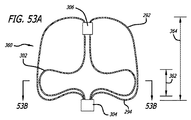
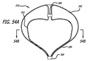
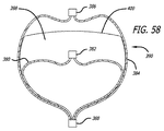
いくつかの実施形態では、外部構造またはシェルは、切頂球体または略ハート状の断面形状を有してもよい。近位部分は、断面が略凸状、半球形、または半円形であってもよい。これらの特徴は、デバイスが、動脈瘤の軸に対する角度配向で脳動脈瘤等の嚢状血管部位の中へ配置されることを可能にする。半円形または半球形の近位表面は、動脈瘤軸の角度測定に関係なく、親血管に比較的一定の形状を提示する。 In some embodiments, the external structure or shell may have a truncated sphere or a generally heart-shaped cross-sectional shape. The proximal portion may be substantially convex, hemispherical, or semicircular in cross section. These features allow the device to be placed into a saccular vessel site such as a cerebral aneurysm with an angular orientation relative to the axis of the aneurysm. The semicircular or hemispherical proximal surface presents a relatively constant shape to the parent vessel regardless of the aneurysm axis angle measurement.
いくつかの実施形態では、内部構造は、内部構造の容量の少なくとも約80%が、外側構造またはシェル容量の下半分またはより近位の半分内に含有されるように、形成されてもよい。いくつかの実施形態に対して、内部構造のメッシュ密度は、外部シェルまたは構造のメッシュ構造の密度より高くてもよい。いくつかの実施形態に対して、内部構造の平均線径は、外部構造の平均線径の約75%未満である。いくつかの実施形態では、構造のワイヤの数による、加重平均直径が重要であってもよい。加重平均は、式N×D=Awによって定義されてもよい。この式において、Nは、ワイヤの数であり、Dは、線径であり、Awは、加重平均直径である。したがって、0.00125インチの直径を有する36本のワイヤおよび0.00075インチの直径を有する108本のワイヤで形成される構造メッシュは、0.126インチの加重平均(Aw)を有する。いくつかの実施形態に対して、内部構造の加重平均直径は、外部構造または透過シェルの加重平均直径の約75%未満であってもよい。 In some embodiments, the inner structure may be formed such that at least about 80% of the volume of the inner structure is contained within the lower half or more proximal half of the outer structure or shell volume. For some embodiments, the mesh density of the inner structure may be higher than the density of the mesh structure of the outer shell or structure. For some embodiments, the average wire diameter of the inner structure is less than about 75% of the average wire diameter of the outer structure. In some embodiments, the weighted average diameter may be important, depending on the number of wires in the structure. The weighted average may be defined by the formula N × D = Aw . In this equation, N is the number of wires, D is the wire diameter, and Aw is the weighted average diameter. Thus, a structural mesh formed of 36 wires having a diameter of 0.00125 inches and 108 wires having a diameter of 0.00075 inches has a weighted average (A w ) of 0.126 inches. For some embodiments, the weighted average diameter of the inner structure may be less than about 75% of the weighted average diameter of the outer structure or permeable shell.
いくつかの実施形態では、患者の血管系の処置のためのデバイスは、近位端、遠位端、および長手軸を有する、自己拡張型弾力性透過構造を含む。 透過構造は、マイクロカテーテル内で送達するために構成される、半径方向に拘束された細長い状態を有する。拡張された弛緩状態において、透過構造は、球状であり長手方向に短縮された構成を有し、半径方向に拘束された状態に対して近位端と遠位端との間の長手軸に沿って延在する。透過シェルはさらに、構造の近位端および遠位端の一方または両方で相互に対して固定される、複数の細長い弾力性フィラメントを含む。 フィラメントは、近位および遠位端を有し、空洞およびシェルの空洞内に配置可能な少なくとも1つの内部構造を画定する、弾力性透過シェルを形成する。シェルおよび少なくとも1つの内部構造を形成する、弾力性フィラメントは、相互に隣接している。 In some embodiments, a device for treatment of a patient's vasculature includes a self-expanding resilient permeable structure having a proximal end, a distal end, and a longitudinal axis. The permeable structure has a radially constrained elongated state configured for delivery within the microcatheter. In the expanded relaxed state, the permeable structure is spherical and has a longitudinally shortened configuration, along the longitudinal axis between the proximal and distal ends relative to the radially constrained state. Extend. The permeable shell further includes a plurality of elongated resilient filaments that are secured to one another at one or both of the proximal and distal ends of the structure. The filament has a proximal and distal end and forms a resilient permeable shell that defines at least one internal structure that can be disposed within the cavity and the cavity of the shell. The elastic filaments forming the shell and at least one internal structure are adjacent to each other.
いくつかの実施形態では、フィラメントは織物であり、フィラメントは、近位端と遠位端との間のデバイスの長手軸から半径方向に拡張される平滑経路の中で、自己拡張型弾力性透過シェルを形成する。フィラメントは、織物フィラメント間の複数の開口部を形成し、該開口部のうちの最大のものは、血栓臨界速度を下回る速度で、開口部を通る血流を可能にするように構成される。 いくつかの実施形態では、内部構造は、拡張状態で、シェルに対して凹状または凸状外面を形成してもよい。 In some embodiments, the filaments are woven and the filaments are self-expanding elastically permeable in a smooth path that is radially expanded from the longitudinal axis of the device between the proximal and distal ends. Form a shell. The filaments form a plurality of openings between the woven filaments, the largest of which is configured to allow blood flow through the openings at a rate below the thrombus critical rate. In some embodiments, the internal structure may form a concave or convex outer surface with respect to the shell in the expanded state.
いくつかの実施形態では、内部構造は、シェルの近位端に取り付けられる円筒形部材またはハブを通過する。この特徴を含む、いくつかの実施形態では、シェルおよび内部構造は、1つ以上の端部で反転した、管状編組等の連続的な可撓性の細長い部材から形成されてもよい。遠位ハブまたはマーカーは、それらがシェル空洞内のシェルの反転部分の直下で一体となる、フィラメントの部分の上に配置されてもよい。本明細書で説明されるように、溶接、はんだ付け、および同等物を含む、シェルフィラメントを円筒形部材に接続する種々の方法が採用されてもよい。示された実施形態では、シェルおよび内部フィラメントは、異なる外形を形成する。 In some embodiments, the internal structure passes through a cylindrical member or hub attached to the proximal end of the shell. In some embodiments, including this feature, the shell and internal structure may be formed from a continuous flexible elongate member, such as a tubular braid, inverted at one or more ends. The distal hub or marker may be placed on the portion of the filament where they come together directly under the inverted portion of the shell within the shell cavity. As described herein, various methods of connecting the shell filament to the cylindrical member may be employed, including welding, soldering, and the like. In the illustrated embodiment, the shell and inner filament form different profiles.
いくつかの実施形態では、遠位ハブまたはマーカーは、デバイスの高さの少なくとも約10%である、最遠位面からの距離を置いて、デバイスの頂面または遠位面より下側に設置されてもよい。いくつかの実施形態では、遠位ハブまたはマーカーは、デバイスの高さの約10%未満である、最遠位面からの距離を置いて、デバイスの頂面または遠位面より下側に設置されてもよい。いくつかの実施形態では、透過シェルおよび少なくとも1つの内部構造を形成するフィラメントは、構造の端部のうちの少なくとも1つ、例えば、近位または遠位端で反転していてもよい。 In some embodiments, the distal hub or marker is placed below the top or distal surface of the device at a distance from the most distal surface that is at least about 10% of the height of the device. May be. In some embodiments, the distal hub or marker is placed below the top or distal surface of the device at a distance from the most distal surface that is less than about 10% of the height of the device. May be. In some embodiments, the permeable shell and the filament forming the at least one internal structure may be inverted at at least one of the ends of the structure, eg, the proximal or distal end.
いくつかの実施形態では、複数の内部構造のそれぞれは、他の内部構造とは異なる拡張直径を有してもよい。この構成では、複数の葉部が、相互の内側で入れ子になり、弛緩状態で複数の放射状の層または葉部を形成してもよい。いくつかの実施形態では、反転は、近位端にあってもよい。したがって、複数の放射状の層が、単一の隣接構造で達成されてもよい。いくつかの実施形態では、内部構造は、相互と一体化して形成される複数の内部構造を備えてもよい。いくつかの実施形態では、反転の数は、約1から約5に及んでもよく、通常は3である。葉部は、より小さい直径を有する葉部が、次に最大の直径の葉部によって形成される空洞内に配置可能あるように、相互の内側で入れ子になって嵌り込んで構成されてもよい。 In some embodiments, each of the plurality of internal structures may have a different expanded diameter than other internal structures. In this configuration, the plurality of leaf portions may be nested inside each other to form a plurality of radial layers or leaf portions in a relaxed state. In some embodiments, the inversion may be at the proximal end. Thus, multiple radial layers may be achieved with a single adjacent structure. In some embodiments, the internal structure may comprise a plurality of internal structures formed integrally with each other. In some embodiments, the number of inversions may range from about 1 to about 5, and is typically 3. The leaves may be configured to nest and fit inside each other so that the leaves with the smaller diameter can then be placed within the cavity formed by the leaves with the largest diameter. .
複数の内部構造のそれぞれは、他の内部構造とは異なる非拡張直径を有してもよい。最小直径を有する内部構造は、シェル空洞内に配置可能である最大直径の内部構造を有する次に最大の直径を有する、内部構造の空洞内に配置可能であってもよい。 Each of the plurality of internal structures may have a different non-expanded diameter than the other internal structures. The internal structure having the smallest diameter may be positionable within the cavity of the internal structure having the next largest diameter with the largest diameter internal structure being positionable within the shell cavity.
本明細書で説明される実施形態のうちのいずれかでは、内部または逆構造は、高表面積内部流バッフルを提供してもよい。複数の同心放射状層は、側壁動脈瘤の中の血流を減速するのに特に有益であってもよい。動脈瘤の中で循環する血液は、複数のメッシュ層を通って流れ、1つの循環流路を完成しなければならない。循環流をそらせることは、急速な止血および血栓症につながる、血流の途絶を提供する。 In any of the embodiments described herein, the internal or inverted structure may provide a high surface area internal flow baffle. Multiple concentric radial layers may be particularly beneficial for slowing blood flow in a side wall aneurysm. Blood circulating in the aneurysm must flow through multiple mesh layers to complete one circulation channel. Diverting the circulation provides a disruption of blood flow that leads to rapid hemostasis and thrombosis.
いくつかの実施形態では、内部または逆構造の総表面積は、約100mm2より大きくてもよい。いくつかの実施形態では、内部または逆構造の総表面積は、デバイスの最大寸法の各センチメートルに対して約100mm2と500mm2との間であってもよい。例えば、1.5cm(直径または長さ)のデバイスでは、内部または逆構造の表面積は、約150mm2と750mm2との間であってもよい。逆に、0.5cm(直径または長さ)のデバイスでは、内部または逆構造の表面積は、約50mm2と250mm2との間であってもよい。 In some embodiments, the total surface area of the internal or inverted structure may be greater than about 100 mm 2 . In some embodiments, the total surface area of the inner or reverse structure may be between about 100 mm 2 and 500 mm 2 for each centimeter of the largest dimension of the device. For example, in a 1.5 cm (diameter or length) device, the surface area of the inner or inverted structure may be between about 150 mm 2 and 750 mm 2 . Conversely, for a 0.5 cm (diameter or length) device, the surface area of the internal or inverted structure may be between about 50 mm 2 and 250 mm 2 .
いくつかの実施形態では、張力を受け、予期しない構成である患者の血管系の処置のためのデバイスでは、少なくとも1つの内部構造およびシェルは、共通の長手軸に沿って延在し、長手方向に離間されてもよい。複数の内部構造を有する実施形態において、張力を受け、予期しない構成である患者の血管系の処置のためのデバイスでは、複数の内部構造およびシェルのそれぞれは、共通の長手軸に沿って延在し、長手方向に離間され、最小直径の内部構造がシェルから長手方向に最も遠く離れている。場合によっては、いったんデバイスが拡張状態になり、内部構造のそれぞれが相互の内側で入れ子になり、最大直径の内部構造がシェル内で入れ子になり、かつシェルに最も近く、または上記で説明されるようにシェルの内周に対して配置可能となると、この構成は、嵌め込み構成を可能にしてもよい。 In some embodiments, in a device for treatment of a patient's vasculature that is under tension and in an unexpected configuration, at least one internal structure and shell extend along a common longitudinal axis and are longitudinal May be spaced apart. In an embodiment having a plurality of internal structures, in a device for treatment of a patient's vasculature that is under tension and in an unexpected configuration, each of the plurality of internal structures and shells extends along a common longitudinal axis However, the longitudinally spaced inner structure with the smallest diameter is furthest away from the shell in the longitudinal direction. In some cases, once the device is in an expanded state, each of the internal structures is nested inside each other, the largest diameter internal structure is nested within the shell, and is closest to the shell, or described above Thus, when it becomes possible to dispose the inner periphery of the shell, this configuration may enable a fitting configuration.
本明細書で説明される実施形態のうちのいずれかでは、オプションの内部または逆構造が、存在する場合、実質的または完全に透過シェルの下部分内にあってもよい。いくつかの実施形態では、内部または逆構造の高さは、シェルの高さの約30%未満であってもよい。いくつかの実施形態では、内部構造の高さは、外部透過シェルの高さの約30%と90%との間であってもよい。本明細書で説明されるデバイス実施形態のうちのいずれかでは、患者の血管系の処置のためのデバイスの透過シェルの近位表面は、形状が凹状、凸状、または円錐形となるように構成されてもよい。場合によっては、円錐型の近位表面は、特に末端動脈瘤に対する血流のより自然な分流または分岐を提供してもよい。 In any of the embodiments described herein, an optional internal or inverted structure, if present, may be substantially or completely within the lower portion of the permeable shell. In some embodiments, the height of the internal or inverted structure may be less than about 30% of the height of the shell. In some embodiments, the height of the inner structure may be between about 30% and 90% of the height of the outer permeable shell. In any of the device embodiments described herein, the proximal surface of the permeable shell of the device for treatment of the patient's vasculature is shaped to be concave, convex, or conical. It may be configured. In some cases, the conical proximal surface may provide a more natural diversion or bifurcation of blood flow, particularly for a distal aneurysm.
いくつかの実施形態では、内部構造の実施形態の遠位端は、接続またはハブで終端してもよい。したがって、内部構造は、シェルの内側近位表面付近でシェルに接続される、シェル内の閉鎖容量を画定してもよい。いくつかの実施形態では、内部構造は、実質的に閉鎖した容量または形状を形成するように、実際の接続または持たないが、内部構造フィラメント融合を有してもよい。内部構造の内部終端があると、外層に影響を及ぼすことなく、または最小に影響を及ぼして、内層の折り重なる能力により、長さの合致および座屈という潜在的問題が最小化されてもよい。いくつかの実施形態では、内部構造は、シェルから別個の葉部を形成する。いくつかの実施形態では、内部構造の折り畳んだ長さは、外部構造の折り畳んだ長さの約80%未満であってもよい。 In some embodiments, the distal end of the internal structure embodiment may terminate at a connection or hub. Thus, the internal structure may define a closed volume within the shell that is connected to the shell near the inner proximal surface of the shell. In some embodiments, the internal structure may have an internal structural filament fusion, although it does not have or have an actual connection to form a substantially closed volume or shape. With the internal termination of the internal structure, the potential problems of length matching and buckling may be minimized by the ability of the inner layer to fold without affecting or minimally affecting the outer layer. In some embodiments, the internal structure forms a separate leaf from the shell. In some embodiments, the folded length of the inner structure may be less than about 80% of the folded length of the outer structure.
いくつかの実施形態では、外部構造は、切頂球体または略ハート状の垂直断面形状を有してもよい。近位部分は、略凸状または半円形であってもよい。これらの特徴は、デバイスが、動脈瘤の軸に対する角度配向で脳動脈瘤等の嚢状血管部位の中へ配置されることを可能にする。半円形の近位表面は、デバイス軸の角度測定に関係なく、親血管に比較的一定の形状を提示する。 In some embodiments, the external structure may have a truncated sphere or a substantially heart-shaped vertical cross-sectional shape. The proximal portion may be generally convex or semi-circular. These features allow the device to be placed into a saccular vessel site such as a cerebral aneurysm with an angular orientation relative to the axis of the aneurysm. The semicircular proximal surface presents a relatively constant shape to the parent vessel regardless of the device axis angle measurement.
いくつかの実施形態では、内部構造は、内部構造の容量の少なくとも約80%が、外側構造またはシェル容量の下半分またはより近位の半分内に含有されるように、形成されてもよい。いくつかの実施形態では、内部構造の容量の少なくとも約80%は、外側構造またはシェルの容量の下またはより近位の80%内に含有されてもよい。いくつかの実施形態に対して、内部構造のメッシュ密度は、外部シェルまたは構造のメッシュ構造の密度より高くてもよい。いくつかの実施形態では、内部構造は、実質的または完全に外部シェル容量の近位または下の80%内にあってもよい。 In some embodiments, the inner structure may be formed such that at least about 80% of the volume of the inner structure is contained within the lower half or more proximal half of the outer structure or shell volume. In some embodiments, at least about 80% of the volume of the inner structure may be contained within 80% below or more proximal to the volume of the outer structure or shell. For some embodiments, the mesh density of the inner structure may be higher than the density of the mesh structure of the outer shell or structure. In some embodiments, the internal structure may be substantially or completely within 80% proximal or below the external shell volume.
場合によっては、外部シェルの内部容量の下部分を占める内部構造は、特に動脈瘤の遠位部分の中で、血栓症の急速な進行を提供してもよい。場合によっては、この構成は、概して、最も弱く、最も破裂しやすいと考えられる、動脈瘤の遠位「ドーム形」部分の保護を提供してもよい。したがって、近位内部構造を有する実施形態は、血管造影法下で可視的であってもよい、動脈瘤の遠位部分を急速に閉塞する方法を提供してもよい。 In some cases, the internal structure that occupies the lower portion of the internal volume of the outer shell may provide rapid progression of thrombosis, particularly in the distal portion of the aneurysm. In some cases, this configuration may provide protection for the distal “dome” portion of the aneurysm, which is generally considered to be the weakest and most likely to rupture. Thus, embodiments having a proximal internal structure may provide a method for rapidly occluding a distal portion of an aneurysm that may be visible under angiography.
内部構造の実施形態は、場合によっては、透過シェルの形成に使用される技法と同様である、本明細書で説明される編組、製織、または他のフィラメント交絡技法、あるいは医療用繊維製品および血管内インプラントに使用される任意の他の好適な技法によって形成されてもよい。代替として、フィラメントは、単にねじられてもよく、またはフィラメントのランダムなメッシュを形成することを許可されてもよい。それは、本明細書で説明されるように、またはシェルを形成するために使用される方法と同様の方法によってヒートセットされてもよく、あるいは、フィラメントが形成されるときに行われるヒートセットを超えて熱処理されなくてもよい。内部構造フィラメントの実施形態は、金属、ポリマー、またはそれらの複合物でできていてもよい。いくつかの実施形態では、フィラメントは、少なくとも約450℃の熱処理に耐えることができる材料で形成される。いくつかの実施形態では、フィラメントのうちのいくつかは、Kevlarという商標の下で入手可能なポリパラフェニレンテレフタルアミド等のアラミド線維で形成されてもよい。いくつかの実施形態では、内部構造フィラメント状部材は、約10ミクロン(0.0004インチ)から約30ミクロン(0.0012インチ)の直径を有するワイヤであってもよい。本明細書で論議される内部構造の実施形態のうちのいずれかは、血栓症および血栓形成を推進する要素または化学物質を放出する材料、被覆を含んでもよい。本明細書で論議される内部構造の実施形態のうちのいずれかはまた、血栓症および血栓形成を推進する要素または化学物質を放出する、粒子または分子で含浸されてもよい。 Embodiments of the internal structure are sometimes similar to the techniques used to form the permeable shell, as described herein, for braiding, weaving, or other filament entanglement techniques, or medical textiles and vessels It may be formed by any other suitable technique used for internal implants. Alternatively, the filaments may simply be twisted or allowed to form a random mesh of filaments. It may be heat set as described herein or by a method similar to that used to form the shell, or beyond the heat set performed when the filament is formed. And need not be heat treated. Inner structural filament embodiments may be made of metal, polymer, or composites thereof. In some embodiments, the filament is formed of a material that can withstand a heat treatment of at least about 450 ° C. In some embodiments, some of the filaments may be formed of aramid fibers such as polyparaphenylene terephthalamide available under the trademark Kevlar. In some embodiments, the internal structural filamentary member may be a wire having a diameter of about 10 microns (0.0004 inches) to about 30 microns (0.0012 inches). Any of the internal structural embodiments discussed herein may include materials, coatings that release elements or chemicals that promote thrombosis and thrombus formation. Any of the internal structural embodiments discussed herein may also be impregnated with particles or molecules that release elements or chemicals that promote thrombosis and thrombus formation.
いくつかの透過シェルの実施形態はまた、拘束状態にある透過シェルが、式1.48((Nldl 2+Nsds 2))1/2によって定義される約0.04インチ未満の外側横径を有するように、拡張状態にある透過シェルの直径と、大型フィラメントの数および直径と、小型フィラメントの数および直径とが構成されるような特性を有してもよく、式中、Nlは、透過シェルの大型フィラメントの数であり、Nsは、透過シェルの小型フィラメントの数であり、dlは、インチ単位の大型フィラメントの直径であり、dsは、インチ単位の小型フィラメントの直径である。 Some transmissive shell embodiments also provide that the permeable shell in the constrained state is less than about 0.04 inches as defined by the equation 1.48 ((N 1 d 1 2 + N s d s 2 )) 1/2 . The outer permeation diameter of the permeable shell in the expanded state, the number and diameter of the large filaments, and the number and diameter of the small filaments may be configured, wherein , N l is the number of large filaments in the transmission shell, N s is the number of small filaments in the transmission shell, d l is the diameter of the large filament in inches, and d s is in inches. The diameter of the small filament.
本明細書で論議される実施形態のうちのいくつかの種々の構成要素および/または要素は、他の実施形態のものと同一または同様の寸法、材料、および/または構成を有してもよい。 Some of the various components and / or elements of the embodiments discussed herein may have the same or similar dimensions, materials, and / or configurations as those of the other embodiments. .
本明細書において、患者の血管系内、特に患者の脳血管系内での低侵襲配備に好適である、血管障害の処置のためのデバイスおよび方法が述べられる。望ましい処置部位へ安全で効率的に送達し、かつ効果的に配備するためのかかる実施形態に対して、いくつかのデバイスの実施形態は、マイクロカテーテルの内側管腔を通した送達、およびその遠位端からの配備に好適な横寸法を有する薄型拘束状態への折り畳みのために構成されてもよい。これらのデバイスの実施形態はまた、患者の血管系内で時間をかけて抵抗するように配備されると、十分な機械的完全性を有する臨床上効率的な構成を維持してもよく、そうでなければ配備されたデバイスの圧縮という結果になる。処置する医師に処置の成功に対してより即時的なフィードバックを提供するために、いくつかのデバイスの実施形態が、手技の経過中に患者の血管障害を急性的に閉塞させることが望ましい場合もある。特に指定のない限り、種々の実施形態の特徴、寸法、または材料のうちの1つ以上は、本明細書で論議される他の同様の実施形態で使用されてもよい。 Described herein are devices and methods for the treatment of vascular disorders that are suitable for minimally invasive deployment within a patient's vasculature, particularly within a patient's cerebral vasculature. In contrast to such embodiments for safe and efficient delivery and effective deployment to a desired treatment site, some device embodiments provide delivery through the inner lumen of a microcatheter and its distal It may be configured for folding into a thin constrained state having a lateral dimension suitable for deployment from the distal end. These device embodiments may also maintain a clinically efficient configuration with sufficient mechanical integrity when deployed to resist over time within a patient's vasculature, and so on. Otherwise it results in compression of the deployed device. It may be desirable for some device embodiments to acutely occlude a patient's vascular disorder during the course of a procedure in order to provide the treating physician more immediate feedback on the success of the procedure. is there. Unless otherwise specified, one or more of the features, dimensions, or materials of the various embodiments may be used in other similar embodiments discussed herein.
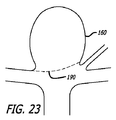
いくつかの実施形態は、患者の血流から血管障害を完全または部分的に隔離するよう、血管壁の再構築による脳動脈瘤の処置に特に有用である。いくつかの実施形態は、血管障害を処置するために、血管障害内に配備され、血管壁の再構築、架橋、または両方を亢進するように構成されてもよい。これらの実施形態のうちのいくつかに対しては、デバイスの透過シェルは、臨床上有益な位置で透過シェルを固着または固定するように構成されてもよい。いくつかの実施形態に対して、デバイスは、血管構造または障害に対して、デバイスを固着または固定するように、血管障害内に完全または部分的に配置されてもよい。透過シェルは、障害が治癒するか、そうでなければ患者の健康への障害の危険性を最小化することを可能にするために、血管障害またはその一部分を患者の公称血管系から隔離するように、血管障害の開口部、頚部、または他の部分に及ぶように構成されてもよい。 Some embodiments are particularly useful for the treatment of cerebral aneurysms by reconstructing the vascular wall to completely or partially isolate the vascular disorder from the patient's bloodstream. Some embodiments may be deployed within a vascular disorder to treat vascular disorders and configured to enhance vascular wall remodeling, cross-linking, or both. For some of these embodiments, the permeable shell of the device may be configured to anchor or secure the permeable shell in a clinically beneficial location. For some embodiments, the device may be placed completely or partially within the vascular disorder to secure or secure the device to the vascular structure or disorder. The permeable shell may isolate the vascular disorder or part thereof from the patient's nominal vasculature to allow the disorder to heal or otherwise minimize the risk of damage to the patient's health. In addition, it may be configured to span an opening, neck, or other portion of a vascular disorder.
本明細書で論議される患者の血管系の処置のためのデバイスの実施形態のうちのいくつかまたは全てに対して、透過シェルは、透過シェルを通る血液のある最初の灌流を可能にするように構成されてもよい。透過シェルの空隙率は、障害の治癒および隔離を促進するように血管障害を十分に隔離するが、デバイスに対して血管系内の血液または他の液体の動的な流れによって膜上に行使される機械力を低減するか、そうでなければ最小化するように、透過シェルを通る十分な最初の流れを可能とするように構成されてもよい。患者の血管系の処置のためのデバイスのいくつかの実施形態に対して、時には欠陥範囲部分と呼ばれる、血管障害の開口部または頚部に及ぶ透過シェルの一部分のみが、患者の血流における血栓形成に対して透過性でありおよび/または貢献する必要がある。かかる実施形態に対しては、血管障害の開口部または頚部に及ばないデバイスのその部分は、大きすぎて血栓形成を効果的に促進できない細孔または開口部構成を伴い、実質的に非透過性または完全に透過性であってもよい。加えて、最初に血流に対して透過性または半透過性である透過シェルの一部分は、デバイスのフィラメント上の血栓形成により、実質的に非透過性または完全に非透過性となってもよい。場合によっては、透過シェルのフィラメントまたはデバイスの任意の他の部分上の血栓形成は、フィラメント間の細孔径を減少させるか、または透過シェルの細孔を完全に閉鎖する働きをしてもよい。 For some or all of the embodiments of the device for treatment of the patient's vasculature discussed herein, the permeable shell allows for some initial perfusion of blood through the permeable shell. May be configured. The porosity of the permeable shell sufficiently isolates the vascular disorder to promote the healing and isolation of the disorder, but is exercised on the membrane by the dynamic flow of blood or other fluid in the vasculature relative to the device It may be configured to allow sufficient initial flow through the permeable shell to reduce or otherwise minimize the mechanical force required. For some embodiments of the device for treatment of the patient's vasculature, only a portion of the permeable lesion spanning the opening or neck of the vascular lesion, sometimes referred to as the defect area portion, is formed in the patient's bloodstream. Needs to be permeable and / or contribute to. For such embodiments, that portion of the device that does not extend to the vascular lesion opening or neck is substantially impermeable with a pore or opening configuration that is too large to effectively promote thrombus formation. Or it may be completely permeable. In addition, a portion of the permeable shell that is initially permeable or semi-permeable to blood flow may become substantially impermeable or completely impermeable due to thrombus formation on the filament of the device. . In some cases, thrombus formation on the filaments of the permeable shell or any other part of the device may serve to reduce the pore size between the filaments or completely close the pores of the permeable shell.
概して、場合によっては、患者内への送達のために薄型に拘束されてもよい、弾力性材料の透過シェルを有する、中空の薄い壁付きデバイスを使用することが望ましい場合がある。かかるデバイスはまた、デバイスのシェルが、より大型容積を想定して充填するか、そうでなければ内部にシェルが配備される血管障害を閉塞するように、拘束を除去すると、半径方向に外向きに拡張するように構成されてもよい。シェルの外向きの半径方向への拡張は、血管障害の内面の一部または全体に係合する働きをしてもよく、それによって、デバイスの透過シェルの外面と、血管障害の内側表面との間の機械的摩擦が、デバイスを血管障害内で効率的に固着する。かかるデバイスのいくつかの実施形態はまた、特に、障害がより大型の内部容量を有する狭い頚部部分を有する、血管障害の空洞内で、部分的または完全に機械的に捕捉されてもよい。送達用の薄型および低容量を達成し、容量による高い拡張率を可能にするために、いくつかのデバイスの実施形態は、依然として適合および容量測定制約を可能としながら、実質的に規則的に離間し安定しているフィラメントの連結または交差間の細孔あるいは開口部パターンを有する、自己拡張型透過シェルを形成するように、織り合わされた構造によって一緒に連結される、織物または編組フィラメントのマトリクスを含む。 In general, in some cases, it may be desirable to use a hollow thin walled device having a permeable shell of resilient material that may be constrained in a low profile for delivery into a patient. Such a device may also radially outward when the restraint is removed so that the shell of the device fills assuming a larger volume or otherwise occludes a vascular disorder in which the shell is deployed. It may be configured to be expanded. The outward radial expansion of the shell may serve to engage part or all of the inner surface of the vascular disorder, thereby allowing the outer surface of the permeable shell of the device to be in contact with the inner surface of the vascular disorder. The mechanical friction between them effectively anchors the device within the vascular lesion. Some embodiments of such devices may also be partially or completely mechanically captured, particularly within a vascular lesion cavity, where the lesion has a narrow neck portion with a larger internal volume. In order to achieve low profile and low volume for delivery and allow high expansion rates by volume, some device embodiments are substantially regularly spaced while still allowing adaptation and volumetric constraints. A matrix of woven or braided filaments joined together by an interwoven structure so as to form a self-expanding permeable shell, with a pore or opening pattern between the filaments or crosses that are stable and stable. Including.
本明細書で使用されるように、織物および編組という用語は、メッシュ構造を形成するフィラメントの織り合わせの任意の形態を意味するように、互換的に使用される。繊維産業または他の産業では、これらの用語は、物品がシートまたは円筒形態で作られるか否か等、製品または用途によって異なる意味あるいはより具体的な意味を有してもよい。本開示の目的のためには、これらの用語は互換的に使用される。 As used herein, the terms woven and braided are used interchangeably to mean any form of interweaving of filaments that form a mesh structure. In the textile industry or other industries, these terms may have different or more specific meanings depending on the product or application, such as whether the article is made in sheet or cylindrical form. For the purposes of this disclosure, these terms are used interchangeably.
いくつかの実施形態に対して、脳動脈瘤の血管内処置において、所望の臨床転帰を達成することができる、患者の血管系の処置のための織物または編組ワイヤ閉塞デバイスにとって、3つの要因が非常に重要であってもよい。いくつかの用途における効果的使用にとって、埋め込みデバイスが、安定性のための十分な半径方向剛性と、ほぼ完全な急性(内部処置)閉塞のための限定孔径と、マイクロカテーテルの内側管腔を通る挿入を可能にするのに十分小型である折り畳み外形とを有することが、望ましくてもよいことが分かっている。ある閾値を下回る半径方向剛性を有するデバイスは、不安定である場合があり、場合によっては、望ましくない移動または血管系の間違った領域の塞栓の危険性がより高くなる場合がある。編組または織物構造におけるフィラメント交差間のより大きい細孔は、急性設定において血栓を生成して血管障害を閉塞しない場合があり、したがって、流れの途絶が、処置されている血管障害の完全で持続的な閉塞に至るという、かかる臨床上のフィードバックを、処置する医師または医療従事者に与えない場合がある。処置する医師が慣れている様式で、蛇行性脳血管系を通るアクセスを可能にするように、標準マイクロカテーテルを通した患者の血管系の処置のためのデバイスの送達が、極めて望ましくてもよい。 For some embodiments, there are three factors for a textile or braided wire occlusion device for treatment of a patient's vasculature that can achieve the desired clinical outcome in endovascular treatment of a cerebral aneurysm: It may be very important. For effective use in some applications, the implantation device passes through a sufficient radial stiffness for stability, a limited pore size for almost complete acute (internal treatment) occlusion, and the inner lumen of the microcatheter. It has been found that it may be desirable to have a folded profile that is small enough to allow insertion. Devices with radial stiffness below a certain threshold may be unstable and in some cases may be at a higher risk of unwanted movement or embolization of the wrong area of the vasculature. Larger pores between filament crossings in a braided or woven structure may produce a thrombus in the acute setting and not occlude vascular disorders, and thus disruption of flow is complete and persistent of the vascular disorder being treated In some cases, such clinical feedback, leading to severe occlusion, is not given to the treating physician or health care professional. Delivery of a device for treatment of a patient's vasculature through a standard microcatheter may be highly desirable to allow access through the tortuous cerebral vasculature in a manner familiar to the treating physician. .
いくつかの実施形態に対して、以下でより詳細に論議されるように、所望の構成を生成するために、透過シェルを形成する2つ以上の異なる直径または横寸法を有するフィラメントを使用することが望ましあり得る。2つのフィラメント(2つの異なる直径)付き織物デバイスの半径方向剛性は、以下の通り、フィラメントの数およびそれらの直径の関数として表され得る。 For some embodiments, as discussed in more detail below, using filaments having two or more different diameters or transverse dimensions to form a permeable shell to produce the desired configuration. May be desirable. The radial stiffness of a textile device with two filaments (two different diameters) can be expressed as a function of the number of filaments and their diameter as follows.
Sradial=(1.2×10⁶lbf/D4)(Nldl 4+Nsds 4)
式中、Sradialは、重量ポンド(lbf)単位の半径方向剛性であり、
Dはデバイスの直径(横寸法)であり、
Nlは大型フィラメントの数であり、
Nsは小型フィラメントの数であり、
dlはインチ単位の大型フィラメントの直径であり、
dsはインチ単位の小型フィラメントの直径である。
S radial = (1.2 × 10 6 lbf / D 4 ) (N l d l 4 + N s ds 4 )
Where S radial is the radial stiffness in pounds of pounds (lbf),
D is the device diameter (lateral dimension);
N l is the number of large filaments,
N s is the number of small filaments,
dl is the diameter of the large filament in inches;
d s is the diameter of the small filament in inches.
この式を使用して、特定の臨床値のいくつかの実施形態に対して、半径方向剛性Sradialは、約0.014と0.284lbfとの間の力であってもよい。 Using this equation, for some embodiments of a particular clinical value, the radial stiffness S radial may be a force between about 0.014 and 0.284 lbf.
患者の血管系の処置のための織物ワイヤデバイスのいくつかの有用な実施形態に対して望ましい、血管障害の頚部または開口部に及ぶデバイスの一部分における最大孔径は、全フィラメントの総数、フィラメントの直径、およびデバイスの直径の関数として表されてもよい。2つ以上のフィラメントの直径または横寸法が使用される、フィラメントのサイズ間の差は、場合によっては、フィラメントのサイズがデバイスの寸法と比較して非常に小型であるデバイスに対しては、無視されてもよい。2つのフィラメント付きデバイス、すなわち、2つの異なるサイズのフィラメントでできているデバイスに対して、最小フィラメント直径が計算に使用されてもよい。したがって、かかる実施形態に対する最大孔径は、以下の通り表されてもよい。 Desirable for some useful embodiments of woven wire devices for treatment of the patient's vasculature, the maximum pore size in the portion of the device that spans the neck or opening of the vascular disorder is the total number of all filaments, the diameter of the filaments , And as a function of device diameter. Differences between filament sizes, where two or more filament diameters or transverse dimensions are used, in some cases, ignored for devices where the filament size is very small compared to the device dimensions May be. For a device with two filaments, ie a device made of two different sized filaments, the minimum filament diameter may be used in the calculation. Accordingly, the maximum pore size for such an embodiment may be expressed as follows:
Pmax=(1.7/NT)(πD−(NTdW/2))
式中、Pmaxは平均孔径であり、
Dはデバイスの直径(横寸法)であり、
NTは全フィラメントの総数であり、
dWはインチ単位のフィラメント(最小)の直径である。
P max = (1.7 / N T ) (πD− (N T d W / 2))
Where P max is the average pore size,
D is the device diameter (lateral dimension);
NT is the total number of all filaments,
d W is the diameter of the filament (minimum) in inches.
この式を使用して、いくつかの実施形態に対して、血管障害の開口部または頚部、あるいはデバイスの任意の他の好適な部分に及ぶデバイスの一部分の最大孔径Pmaxは、約0.016インチまたは約400ミクロン未満であってもよい。ある実施形態では、欠陥範囲部分、またはデバイスの任意の他の好適な部分に対する最大孔径は、約0.012インチまたは約300ミクロン未満であってもよい。 Using this equation, for some embodiments, the maximum pore size P max of a portion of the device spanning the opening or neck of a vascular disorder, or any other suitable portion of the device is about 0.016. It may be less than an inch or about 400 microns. In certain embodiments, the maximum pore size for the defect area portion, or any other suitable portion of the device, may be less than about 0.012 inches or about 300 microns.
2つのフィラメント(2つの異なるフィラメントの直径を有する外形)付き織物フィラメントデバイスの折り畳み外形は、関数として表されてもよい。 The folded profile of a woven filament device with two filaments (an outline having the diameter of two different filaments) may be expressed as a function.
Pc=1.48((Nldl 2+Nsds 2))1/2
式中、Pcはデバイスの折り畳み外形であり、
Nlは大型フィラメントの数であり、
Nsは小型フィラメントの数であり、
dlはインチ単位の大型フィラメントの直径であり、
dsはインチ単位の小型フィラメントの直径である。
P c = 1.48 ((N l d l 2 + N s d s 2 )) 1/2
Where P c is the folded outline of the device,
N l is the number of large filaments,
N s is the number of small filaments,
dl is the diameter of the large filament in inches;
d s is the diameter of the small filament in inches.
この式を使用して、特定の臨床値のいくつかの実施形態に対して、折り畳み外形Pcは約1.0mm未満であってもよい。特定の臨床値のいくつかの実施形態では、デバイスは、上記で論議された範囲内の上記3つの因数(Sradial、Pmax、およびPc)全て、すなわち、約0.014lbfと0.284lbfとの間のSradial、約300ミクロン未満のPmax、および約1.0mm未満のPcを同時に有するように構築されてもよい。いくつかのかかる実施形態では、デバイスは、約70個から約300個のフィラメントを含むように作製されてもよい。場合によっては、フィラメントは、約0.0004インチから約0.002インチの外側横寸法または直径を有してもよい。 Using this formula, for some embodiments of a particular clinical value, the folded profile P c may be less than about 1.0 mm. In some embodiments of a particular clinical value, the device may have all three factors (S radial , P max , and P c ) within the ranges discussed above, ie, about 0.014 lbf and 0.284 lbf. May be constructed to simultaneously have a S radial between, a P max of less than about 300 microns, and a P c of less than about 1.0 mm. In some such embodiments, the device may be made to include about 70 to about 300 filaments. In some cases, the filaments may have an outer lateral dimension or diameter of about 0.0004 inches to about 0.002 inches.
論議されてきたように、患者の血管系の処置のためのデバイスのいくつかの実施形態は、血管部位を充填するために、血管部位の寸法に近似する(または若干の過大寸法を有する)デバイスのサイズに合わせることを要求する。より大型寸法へのデバイスのスケーリング、およびより大型のフィラメントの使用は、デバイスのかかるより大型の実施形態には十分だろうと推定されるかもしれない。しかしながら、脳動脈瘤の処置に対して、半径方向に折り畳まれたデバイスの直径または外形は、脳の小さく蛇行する血管内を効率的に進むことができるカテーテルのサイズによって制限される。さらに、デバイスは、所与のサイズまたは厚さを有する所与の数または固定数の弾力性フィラメントを伴って、より大型に作製されるので、フィラメントの接合部間の細孔または開口部は、対応してより大型になる。加えて、所与のフィラメントのサイズに対して、フィラメントの曲げ弾性率または剛性、すなわち構造は、デバイスの寸法が増加するにつれて減少する。曲げ弾性率は、歪みに対する応力の比として定義されてもよい。したがって、歪み(偏向)が所与の力を下回って低い場合、デバイスは、高い曲げ弾性率を有するか、または剛性があると考えられ得る。剛性デバイスはまた、低い追従性を有すると言われてもよい。 As has been discussed, some embodiments of devices for treatment of a patient's vasculature are devices that approximate (or have some oversize) the dimensions of a vascular site to fill the vascular site. Require to adapt to the size of. It may be assumed that scaling the device to larger dimensions and using larger filaments would be sufficient for such larger embodiments of the device. However, for the treatment of cerebral aneurysms, the diameter or contour of the radially folded device is limited by the size of the catheter that can be efficiently advanced within the small and meandering blood vessels of the brain. Furthermore, since the device is made larger with a given or fixed number of elastic filaments having a given size or thickness, the pores or openings between the filament junctions are Correspondingly larger. In addition, for a given filament size, the flexural modulus or stiffness, or structure, of the filament decreases as the device dimensions increase. Flexural modulus may be defined as the ratio of stress to strain. Thus, if the strain (deflection) is low below a given force, the device can be considered to have a high flexural modulus or be rigid. A rigid device may also be said to have low trackability.
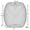
患者の血管系の処置のためのより大型サイズのデバイスを適切に構成するために、デバイスが、弛緩した非拘束状態にあるデバイスの公称直径または横寸法より小さい直径または横寸法を有する血管または動脈瘤等の血管部位または障害の中へ配備されるときに、デバイスへの力をモデル化することが有用であり得る。論議されるように、場合によっては、デバイスの外面と血管壁の内面との間に残留力があるように、デバイスを「過大にする」ことが賢明であり得る。過大であることに起因するデバイス10への内側半径方向力は、図1に図式的に図示され、図中の矢印12は内側半径方向力を表す。図2に示されるように、図1のデバイスのフィラメント14へのこれらの圧縮力は、図中の矢印18によって示されるように、分布荷重または力を有する単純支持ビーム16として、モデル化することができる。2つの単純支持部20を有するビームのたわみと分布荷重とについての以下の式から、たわみは、長さLの4乗の関数であることが分かる。
To properly configure a larger size device for treatment of a patient's vasculature, a blood vessel or artery where the device has a diameter or transverse dimension that is smaller than the nominal or transverse dimension of the device in a relaxed, unconstrained state It may be useful to model the force on the device when deployed into a vascular site or disorder such as an aneurysm. As discussed, in some cases it may be advisable to “oversize” the device so that there is a residual force between the outer surface of the device and the inner surface of the vessel wall. The inner radial force on the
ビームのたわみ=5FL4/384EI
式中、F=力、
L=ビームの長さ、
E=ヤング率、
I=慣性モーメントである。
Deflection of beam = 5FL 4 / 384EI
Where F = force,
L = length of the beam,
E = Young's modulus,
I = moment of inertia.
したがって、デバイスのサイズが増加し、Lが増加すると、追従性が大幅に増加する。それゆえ、血管または動脈瘤等の血管部位の中に挿入されるときの拘束力に対する、デバイス10のフィラメント14の外面によって及ぼされる外側半径方向力は、所与の量のデバイスの圧縮または過大に対して、より低い。いくつかの用途において、この力は、デバイスの安定性を保証するため、ならびにデバイスの遊走の危険性および遠位塞栓形成の可能性を低減するために重要であり得る。
Therefore, as the size of the device increases and L increases, the followability greatly increases. Therefore, the outer radial force exerted by the outer surface of the
いくつかの実施形態では、望ましい半径方向の追従性を有するデバイスを作製し、かつ一般に使用されるマイクロカテーテルの内側管腔を通って嵌合するように構成される折り畳み外形を有するように、小型および大型フィラメントのサイズの併用が利用されてもよい。少数の比較的大型のフィラメント14によって製造されるデバイスは、全て小型のフィラメントによって作製されたデバイスと比較して、低減した半径方向追従性(または増加した剛性)を提供することができる。比較的少数のより大型のフィラメントさえも、フィラメントの総断面積を増加させることなく、直径の増加に起因する慣性モーメントの変化によって、曲げ剛性の多大な増加を提供し得る。円形ワイヤまたはフィラメントの慣性モーメント(I)は、以下の式によって定義され得る。
In some embodiments, the device is made compact to create a device with the desired radial compliance and to have a folded profile that is configured to fit through the inner lumen of a commonly used microcatheter. And a combination of large filament sizes may be utilized. Devices made with a small number of relatively
I=πd4/64
式中、dはワイヤまたはフィラメントの直径である。
I = πd 4/64
Where d is the diameter of the wire or filament.
慣性モーメントはフィラメント直径の4乗の関数であるので、直径の小さな変化は、慣性モーメントを大きく増加させる。したがって、フィラメントサイズの小さな変化は、所与の荷重におけるたわみ、したがってデバイスの追従性に多大な影響を及ぼすことができる。 Since the moment of inertia is a function of the fourth power of the filament diameter, a small change in diameter greatly increases the moment of inertia. Thus, small changes in filament size can have a significant impact on deflection at a given load and thus device followability.
したがって、剛性は、デバイス10の折り畳み外形の断面積の大きな増加を伴わずに、有意量で増加させることができる。これは、デバイスの実施形態が大型動脈瘤を処置するために大きく作られるときに特に重要であり得る。大型脳動脈瘤は比較的珍しいが、医師が現在使用可能である一部の閉塞デバイスは、より小型の動脈瘤と比べて、比較的不良な結果を有するので、それらは重要な処置課題を提示している。
Thus, the stiffness can be increased in a significant amount without a significant increase in the cross-sectional area of the folded profile of the
このように、患者の血管系の処置のためのデバイスのいくつかの実施形態は、2つ、3つ、4つ、5つ以上の異なる直径または横寸法等のいくつかの異なる直径を有するフィラメント14の組み合わせを使用して、形成されてもよい。2つの異なる直径を有するフィラメントが使用されるデバイスの実施形態では、いくつかのより大型のフィラメントの実施形態は、約0.001インチから約0.004インチの横寸法を有してもよく、いくつかの小型フィラメントの実施形態は、約0.0004インチおよび約0.0015インチ、より具体的には、約0.0004インチから約0.001インチまでの横寸法または直径を有してもよい。いくつかの構造は、最大約0.001インチの横寸法を有するフィラメントを使用してもよい。小型フィラメントの数に対する大型フィラメントの数の比は、約2と12との間であってもよく、また、約4と8との間であってもよい。いくつかの実施形態では、より大型とより小型のフィラメントとの直径または横寸法の差は、約0.004インチ未満、より具体的には、約0.0035インチ未満、さらにより具体的には、約0.002インチ未満であってもよい。概して上記で論議されたように、常に全てのワイヤまたはフィラメントが、本明細書で論議される種々の関係に対するパラメータを満たす必要はなくてもよい。これは、比較的多数のフィラメントが明確に異なる構造に使用されている場合に特に当てはまってもよい。場合によっては、フィラメント状構造は、透過シェルまたは内部構造のフィラメントの優位がサイズ制約を満たす、本明細書で論議される関係制約を満たしてもよい。 Thus, some embodiments of a device for treatment of a patient's vasculature are filaments having several different diameters, such as two, three, four, five or more different diameters or transverse dimensions Fourteen combinations may be used to form. In device embodiments where filaments having two different diameters are used, some larger filament embodiments may have a lateral dimension of about 0.001 inches to about 0.004 inches, Some small filament embodiments may have lateral dimensions or diameters of about 0.0004 inches and about 0.0015 inches, more specifically about 0.0004 inches to about 0.001 inches. Good. Some structures may use filaments having a lateral dimension up to about 0.001 inch. The ratio of the number of large filaments to the number of small filaments may be between about 2 and 12, and may be between about 4 and 8. In some embodiments, the difference in diameter or lateral dimension between the larger and smaller filaments is less than about 0.004 inches, more specifically less than about 0.0035 inches, and even more specifically. Less than about 0.002 inches. In general, as discussed above, it is not always necessary that all wires or filaments meet the parameters for the various relationships discussed herein. This may be especially true when a relatively large number of filaments are used in distinctly different structures. In some cases, the filamentary structure may meet the relationship constraints discussed herein, where the dominance of the permeable shell or internal structure filaments meets the size constraint.
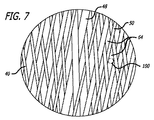
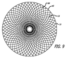
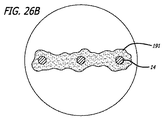
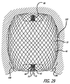
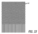
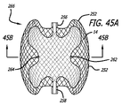
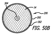
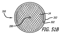
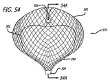
上記で論議されたように、患者の血管系の処置のためのデバイス10の実施形態は、透過シェルとしての機能を果たす構造を形成する、複数のワイヤ、繊維、糸、管、または他のフィラメント状要素を含んでもよい。いくつかの実施形態に対して、球形は、管状編組構造の端部を接続または固定することによって、かかるフィラメントから形成されてもよい。かかる実施形態に対して、編組または織物構造の密度は、本来的には、ワイヤまたはフィラメント14が一緒に引き寄せられた端部において、またはその付近において増加し、透過シェル40の近位端32と遠位端34との間に配置される中間部分30において、またはその付近において減少し得る。いくつかの実施形態に対して、透過シェル40の端部または任意の他の好適な部分は、処置のために動脈瘤等の血管障害の開口部または頚部の中に設置されてもよい。このように、透過シェルを有する編組または織物フィラメントデバイスは、血管障害の止血および閉塞を達成するために、透過シェルの公称部分とは異なる特性を有する別個の欠陥範囲構造の追加を必要としなくてもよい。かかるフィラメントデバイスは、編組、製織、または他の好適なフィラメント製造技術によって製造されてもよい。かかるデバイスの実施形態は、本明細書で論議されるような種々の3次元形状に形状設定されてもよい。
As discussed above, an embodiment of the
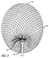
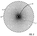
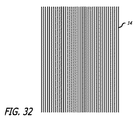
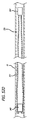
図3−10を参照すると、患者の血管系の処置のためのデバイス10の実施形態が示されている。デバイス10は、近位端32、遠位端34、および長手軸46を有し、図5、7、および18においてより詳細に示されるように、少なくとも2つの異なる横寸法の大型フィラメント48および小型フィラメント50を含む複数の細長い弾力性フィラメント14をさらに備える自己拡張型弾力性透過シェル40を含む。フィラメント14は、織物構造を有し、その近位端60および遠位端62において相互に対して固定される。デバイスの透過シェル40は、フィラメントの長さに沿って相互に半径方向に隣接して、近位端42から遠位端44まで長手方向に延在する薄い織物フィラメント14を伴い、図11に示されるように、マイクロカテーテル61内への送達のために構成される半径方向に拘束された細長い状態を有する。
With reference to FIGS. 3-10, an embodiment of a
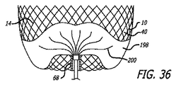
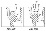
図3−6に示されるように、透過シェル40はまた、球状であり長手方向に短縮された構成を有する、半径方向に拘束された状態に対して拡張された弛緩状態を有する。拡張状態では、織物フィラメント14は、近位端32と遠位端34との間のデバイスの長手軸46から半径方向に拡張される平滑経路の中で、自己拡張型弾力性透過シェル40を形成する。 フィラメント14の織物構造は、織物フィラメントの間に形成される透過シェル40の複数の開口部64を含む。いくつかの実施形態に対して、開口部64のうちの最大のものは、血栓臨界速度を下回る速度で開口部のみを通る血流を可能にするように構成されてもよい。血栓臨界速度は、患者の血管系内に配備されるときに、血管グラフト表面の50%より多くが血栓によって被覆される時間平均速度として、少なくとも一部の人によって定義されている。動脈瘤閉塞との関連で、わずかに異なる閾値が適切であり得る。それゆえ、本明細書で使用されるような血栓臨界速度は、デバイスによって処置される血管障害の中への血流が、約1時間未満後に、そうでなければ処置手技中に実質的に遮断されるように、患者の血管系内に配備されるデバイス10等のデバイス内または上に凝固が生じる速度を含むものとする。場合によっては、血管障害の中への血流の遮断は、十分な量の造影剤が患者の埋め込み部位の血管系上流の中に注入され、その部位から消散するにつれ可視化された後に、血管障害に進入する最低限の造影剤によって示されてもよい。埋め込み手技の約1時間未満内または埋め込み手技中の流れのかかる持続的遮断はまた、血管障害の急性閉塞と呼ばれてもよい。
As shown in FIGS. 3-6, the
このように、いったんデバイス10が配備されると、透過シェルを通って流れる血液は、血栓臨界速度を下回る速度まで減速され得、血栓が透過シェル40の中の開口部上およびその周囲に形成し始める。最終的に、この過程は、その内側にデバイス10が配備される血管障害の急性閉塞を生じるように構成され得る。いくつかの実施形態に対して、透過シェル40の少なくとも遠位端は、フィラメント14の固定された遠位端62が、拡張状態にある名目的透過シェル構造または外形内で軸方向に引き抜かれるように、裏返された構成の逆屈曲を有してもよい。いくつかの実施形態に対して、透過シェルの近位端はさらに、フィラメント14の固定された近位端60が、拡張状態にある名目的透過シェル構造40内で軸方向に引き抜かれるように、裏返された構成の逆屈曲を含む。本明細書で使用されるように、裏返されたという用語は、図3−6のデバイスの実施形態で示されるように、裏返された、部分的に裏返された、および/または逆屈曲を伴って陥凹した構造を含んでもよい。かかる実施形態に対して、透過シェルのフィラメント14の端部60および62、または端部の周囲に配置されるハブ構造は、デバイスの透過シェルの球形周囲内に、またはそれより下側に引き抜かれてもよい。
Thus, once the
透過シェル40の細長い弾力性フィラメント14は、溶接、半田付け、接着、エポキシ接着等を含む1つ以上の方法によって、その近位端60および遠位端62において相互に対して固定されてもよい。フィラメントの端が一緒に固定されることに加えて、遠位ハブ66はまた、透過シェル40の細いフィラメント14の遠位端62に固定されてもよく、近位ハブ68は、透過シェル40の細いフィラメント14の近位端60に固定されてもよい。近位ハブ68は、近位ハブ68の近位部分内に空洞70を形成するように、細いフィラメント14の近位端60を越えて近位に延在する円筒形部材を含んでもよい。近位空洞70は、図11−15に示されるような送達装置に着脱可能に固定され得る細長い着脱テザー72を固定するためのエポキシ、半田、または任意の他の好適な結合剤等の接着剤を保持するために使用されてもよい。
The elongated
いくつかの実施形態に対して、透過シェル40の細長い弾力性フィラメント14は、実質的に円形状である横断面を有してもよく、形状記憶金属であってもよい超弾性材料から作製されてもよい。透過シェル40のフィラメントの形状記憶金属は、図3−6に示されるように、弛緩した拡張状態の球状構成にヒートセットされてもよい。好適な弾力性形状記憶金属は、NiTi合金および同等物等の合金を含んでもよい。かかる合金の超弾性特性は、合金を示された球状形態にヒートセットし、マイクロカテーテルの内側管腔内への送達のために完全に拘束し、次いで患者の体内に配備されると、球状構成の元来のヒートセット形状へと実質的に戻って自己拡張するように解放することができるように、細長いフィラメント14に弾力性特性を提供するのに有用であってもよい。
For some embodiments, the elongated
デバイス10は、拡張された弛緩状態において近位端32および遠位端34を有する透過シェル40を有する裏返されたフィラメント状構造を有してもよい。透過シェル40は、示された実施形態に対して、実質的に閉鎖された構成を有する。デバイス10の透過シェル40のいくつかまたは全ては、デバイスが拡張状態に配備された後のいくらかの期間にわたって、血管障害の中への液体の流れまたは圧力を実質的に遮断するか、または妨げ、そうでなければ血管障害を隔離するように構成されてもよい。透過シェル40およびデバイス10はまた、概して、近位端32、遠位端34、および長手軸46を含む細長い管状または円筒形構成を伴って、図11に示されるような薄型の半径方向に拘束された状態も有する。半径方向に拘束された状態にある間、透過シェル40の細長い可撓性フィラメント14は、近位端と遠位端との間において相互と実質的に平行かつ近接して配置され、実質的に管状または圧縮円筒形構成を形成し得る。
The
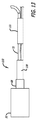
透過シェル40のフィラメント14の少なくともいくつかの近位端60は、近位ハブ68に固定されてもよく、透過シェル40のフィラメント14の少なくともいくつかの遠位端62は、遠位ハブ66に固定され、近位ハブ68および遠位ハブ66は、図4に示されるように長手軸46に対して実質的に同心円状に配置されている。フィラメント14の端部は、接着剤、半田、溶接等の使用を含む、相互へのフィラメント端部の固定に関する上記で論議された方法のうちのいずれかによって、それぞれのハブ66および68に固定されてもよい。透過シェル40の中間部分30は、図11に示されるように、マイクロカテーテルからの送達に好適な薄型外形を有する第1の横寸法を有してもよい。デバイス10上の半径方向の拘束は、示されたマイクロカテーテル61の遠位端部分等のマイクロカテーテルの内側管腔の内面によって適用されてもよく、またはカテーテルの遠位端からデバイス10が排出されると制御可能に解放されてもよい、任意の他の好適な機構によって適用されてもよい。図11において、デバイス10の近位端またはハブ68は、デバイス10の近位ハブ68に配置される送達システム112の細長い送達装置110の遠位端に固定される。
At least some proximal ends 60 of the
編組または織物フィラメント状構造を有する、いくつかのデバイス実施形態10は、約10個のフィラメントから約300個のフィラメント14、より具体的には、約10個のフィラメントから約100個のフィラメント14、さらにより具体的には、約60個のフィラメントから約80個のフィラメント14を使用して形成されてもよい。透過シェル40のいくつかの実施形態は、近位端32から遠位端34まで延在する約70個のフィラメントから約300個のフィラメント、より具体的には、近位端32から遠位端34まで延在する約100個のフィラメントから約200個のフィラメントを含んでもよい。いくつかの実施形態に対して、フィラメント14は、約0.0008インチから約0.004インチの横寸法または直径を有してもよい。場合によっては、細長い弾力性フィラメント14は、約0.0005インチから約0.005インチ、より具体的には、約0.001インチから約0.003インチ、およびある場合には、約0.0004インチから約0.002インチの外側横寸法または直径を有してもよい。異なるサイズのフィラメント14を含む、いくつかのデバイス10の実施形態に対して、透過シェル40の大型フィラメント48は、約0.001インチから約0.004インチである横寸法または直径を有してもよく、小型フィラメント50は、約0.0004インチから約0.0015インチ、より具体的には、約0.0004インチから約0.001インチの横寸法または直径を有してもよい。加えて、小型フィラメント50と大型フィラメント48との間の横寸法または直径の差は、約0.004インチ未満、より具体的には、約0.0035インチ未満、さらにより具体的には、約0.002インチ未満であってもよい。異なるサイズのフィラメント14を含む透過シェル40の実施形態に対して、透過シェル40の大型フィラメント48の数に対する透過シェル40の小型フィラメント50の数は、約2対1から約15対1、より具体的には、約2対1から約12対1、さらにより具体的には、約4対1から約8対1であってもよい。
Some
図4に示されるように、透過シェル40の拡張された弛緩状態は、近位ハブ68が拘束状態にあるよりも遠位ハブ66の近くに配置されるように、拘束状態に対して軸方向に短縮される構成を有する。ハブ66および68の両方は、デバイスの長手軸46に対して実質的に同心円状に配置され、各フィラメント要素14は、各端部に逆屈曲を有する近位ハブ66と遠位ハブ68との間に平滑な弧を形成する。いくつかの実施形態に対して、配備された弛緩状態にある透過シェル40の近位ハブ66と遠位ハブ68との間の縦間隔は、拘束された円筒状態にある近位ハブ66と遠位ハブ68との間の縦間隔の約25%から約75%であってもよい。近位端32と遠位端34との間にあるフィラメント14の弧は、各フィラメント14の中間部分が、第1の横寸法より実質的に大きい第2の横寸法を有するように構成されてもよい。
As shown in FIG. 4, the expanded relaxed state of the
いくつかの実施形態に対して、透過シェル40は、約0.2mmから約2mmの折り畳み半径方向に拘束した状態での第1の横寸法、および約4mmから約30mmの弛緩した拡張状態での第2の横寸法を有してもよい。いくつかの実施形態に対して、拡張状態にある透過シェル40の第2の横寸法は、第1の横寸法の約2倍から約150倍、より具体的には、第1または拘束横寸法の約10倍から約25倍であってもよい。弛緩した拡張状態にある透過シェル40の近位端32と遠位端34との間の縦間隔は、拘束された円筒状態である近位端32と遠位端34との間の間隔の約25%から約75%であってもよい。いくつかの実施形態に対して、弛緩した拡張状態にある透過シェル40の主要横寸法は、約4mmから約30mm、より具体的には、約9mmから約15mm、さらにより具体的には、約4mmから約8mmであってもよい。
For some embodiments, the
透過シェル40のフィラメント14の弧形部分は、図6に示されるように、透過シェル40の端部の付近に、第1のまたは外半径88、および第2のまたは内半径90を有する正弦様形状を有してもよい。この正弦様または多曲線形状は、血管障害に隣接する親血管の中の流れの閉鎖を低減し得、近位端32の中に陥凹部を提供し得る。いくつかの実施形態に対して、透過シェル40の第1の半径88および第2の半径90は、約0.12mmと約3mmとの間であってもよい。いくつかの実施形態に対して、近位端32と遠位端34との間の距離は、いくつかの実施形態に対する透過シェル40の全体的長さの約60%未満であってもよい。かかる構成により、デバイス10が遠位端34において抵抗を受けるときに、遠位端34が近位端32に向かって下方に曲がることが可能になり得、したがって、長手方向の適合が提供されてもよい。フィラメント14は、いくつかの実施形態では、約2mmよりも大きい距離にわたる湾曲を伴わない部分がないように成形されてもよい。したがって、いくつかの実施形態に対して、各フィラメント14は、実質的に連続的な湾曲を有してもよい。この実質的に連続的な湾曲は、スムースな配備を提供してもよく、血管穿孔の危険性を低減してもよい。いくつかの実施形態に対して、端部32または34のうちの1つは、他方の端部より長手または軸方向に共形であるように、他方より大きい程度まで後退させられるか、または裏返されてもよい。
The arcuate portion of the
いくつかの実施形態に対して、透過シェル40の第1の半径88および第2の半径90は、約0.12mmと約3mmとの間であってもよい。 いくつかの実施形態に対して、近位端32と遠位端34との間の距離は、拡張した透過シェル40の全体的長さの約60%より大きくてもよい。したがって、内面間の最大長手方向距離は、外面の長手方向長さまたはデバイス10の全体的長さの約60%から約90%であってもよい。近位端32および遠位端34におけるハブ66とハブ68との間の間隙は、デバイス10が遠位端で抵抗を受けるときに、遠位ハブ66が近位ハブ68に向かって下向きに曲がることを可能にしてもよく、したがって、長手方向の適合を提供する。フィラメント14は、約2mmよりも大きい距離にわたる湾曲を有しない部分がないように成形されてもよい。したがって、いくつかの実施形態に対して、各フィラメント14は、実質的に連続的な湾曲を有してもよい。この実質的に連続した湾曲は、スムースな配備を提供し得、血管穿孔の危険性を低減し得る。遠位端34は、透過シェル40の遠位端部分が、近位端部分より半径方向に共形であり得るように、近位端32より大きい程度まで後退させられるか、または裏返されてもよい。遠位端部分の適合は、不整形な形状の動脈瘤または他の血管障害へのより優れたデバイスの適合を提供してもよい。デバイスの凸面は、血管部位の湾曲に適合するように、凹面を形成して内側に曲がってもよい。
For some embodiments, the
図10は、近位ハブ68の外側リングによって拘束され、緊密に詰められた2つの異なるサイズのフィラメント14を有するデバイス10の近位ハブ68内に配置されたフィラメント14の拡大図を示す。テザー部材72は、随意で、フィラメント14の中間部分内に、または図6に示されるようにフィラメント14の近位端60の近位にある近位ハブ68の空洞70内に配置されてもよい。テザー72の遠位端は、近位ハブ68の近位段部分94によって形成される近位ハブ68の空洞70の中に機械的に捕捉される、その遠位端に形成される結節92で固定されてもよい。テザー72の結節遠位端92はまた、空洞70内でのテザー72の遠位端の接着またはポッティングによって、随意で、機械的圧縮、接着、溶接、半田付け、ろう付け、または同等物を用いてフィラメント14の近位端60の間で固定されてもよい。図6に示されるテザー72の実施形態は、接着剤で近位ハブ68の空洞にポッティングされた、結節遠位端92を有する。かかるテザー72は、図11および図23−26に示されるように、デバイス10を配備するために使用される送達装置110の一部であってもよい、溶解可能、切断可能、または解放可能なテザーであってもよい。 図10はまた、近位ハブ68の外側リング内で相互に対して適所に大型および小型フィラメント48および50を固定するように構成される近位ハブ68内に配置され、近位ハブ68によって拘束された、大型フィラメント48および小型フィラメント50も示す。
FIG. 10 shows an enlarged view of the
図7および8は、患者の血管系の処置のためのデバイス10の透過シェル40の編組フィラメント14のいくつかの構成実施形態を図示する。各実施形態の編組構造は、各隣接フィラメントセグメントに接触する円形形状100を伴い、織物または編組構造の細孔64内に配置される円形形状100と共に示されている。細孔開口部サイズは、編組のフィラメント要素14のサイズ、相互に対する角度重複フィラメントの作り、および編組構造の1インチあたりの打ち込み本数によって、少なくとも部分的に決定されてもよい。いくつかの実施形態に対して、セルまたは開口部64は、図7に示されるように、細長い実質的にひし形の形状を有してもよく、透過シェル40の細孔または開口部64は、図8に示されるように、デバイス10の中間部分30に向かって実質的により正方形の形状を有してもよい。ひし形の細孔または開口部64は、特にハブ66および68の付近の幅よりも実質的に大きい長さを有してもよい。いくつかの実施形態では、幅に対するひし形の細孔または開口部の長さの比は、いくつかのセルについては、3対1の比を超えてもよい。ひし形開口部64は、幅よりも大きい長さを有してもよく、したがって、1より大きい長さ/幅として定義される縦横比を有する。ハブ66および68の付近の開口部64は、図7に示されるようなハブからさらに遠いものよりも大幅に大きい縦横比を有してもよい。ハブに隣接する開口部64の縦横比は、約4対1よりも大きくてもよい。最大直径付近の開口部64の縦横比は、いくつかの実施形態に対して、約0.75対1と約2対1との間であってもよい。いくつかの実施形態に対しては、透過シェル40の中の開口部64の縦横比は、約0.5対1から約2対1であってもよい。
7 and 8 illustrate several configuration embodiments of the
開口部64を囲むフィラメント14を変位させるかまたは歪めることなく、透過シェル40の編組構造の開口部64内に配置されてもよい、最大円形形状100によって画定される孔径は、実施形態に対して、約0.005インチから約0.01インチ、より具体的には、約0.006インチから約0.009インチ、さらにより具体的には、約0.007インチから約0.008インチまでのサイズに及んでもよい。加えて、デバイス10の透過シェル40の隣接するフィラメント14の間に形成される、開口部64のうちの少なくともいくつかは、血栓臨界速度を下回る速度で、開口部64のみを通る血流を可能にするように構成されてもよい。いくつかの実施形態に対して、透過シェル構造40の中の最大開口部64は、血栓臨界速度を下回る速度で、開口部64のみを通る血流を可能にするように構成されてもよい。上記で論議されたように、孔径は、いくつかの実施形態に対して、約0.016インチ未満、より具体的には、約0.012インチ未満であってもよい。いくつかの実施形態に対して、隣接するフィラメント14の間に形成される開口部64は、約0.005インチから約0.04インチであってもよい。
The pore size defined by the largest
図12−15を参照すると、図11の送達システム112の送達装置110の実施形態が、より詳細に示されている。装置110は、図12に示されるように、装置110の近位端116から装置110の遠位部118まで延在する、細長いコアワイヤ114を含む。コアワイヤ114は、図11に示されるように、送達システム112のマイクロカテーテル61の内側管腔120を通して、患者の血管系の処置のための拘束されたデバイス10を押すのに十分な支柱強度を提供するように構成される。 コアワイヤ114はまた、マイクロカテーテル61の外側の位置から、およびマイクロカテーテル61の管腔120内で軸方向に、デバイス10を引き抜くか、または近位に後退させるのに十分な引張強度も有する。近位ハブ68から近位に延在するテザー72は、テザー72の一部分およびコアワイヤ114の遠位部を覆って配置され、図13に示されるように両方を覆って収縮される、1本の収縮可能管類122を用いてコアワイヤ114の遠位端に固定されるが、任意の他の好適な固定手段が使用されてもよい。
Referring to FIGS. 12-15, an embodiment of the
第1の導体126および第2の導体128に電気的に連結されるヒータコイル124は、テザー72の最遠位部分を覆って配置される。ヒータコイル124はまた、熱遮蔽としての役割を果たす働きをし、ヒータコイル124から送達装置110の周囲にある患者の血流等の環境の中への熱の漏出を最小化する、熱収縮管類122の遠位にあるヒータコイル124を覆って配置される、1本のポリマー管類130で覆われてもよい。いったん熱収縮管類122および絶縁ポリマー管類130が、装置110の遠位部118に固定されると、熱収縮管類122の近位に配置されたテザー72の近位部分は、図13に示されるように切り取られてもよい。次いで、送達装置110の遠位端134から装置110の近位部136まで延在するオーバーコイル132が、ヒータコイル124、コアワイヤ114、テザー72、第1の導体126、および第2の導体128を覆って配置されてもよく、これらの要素を一緒に担持し、低摩擦外面を生成し、送達装置110の望ましい可撓性を維持する。装置110の近位部136は、それぞれ図15に示されるように、コアワイヤ114の近位部136の周囲で円周方向に配置され、そこから絶縁され、第1の導体126および第2の導体128に電気的に連結される、第1の接点138および第2の接点140の遠位に配置されるオーバーコイル132の近位末端を含む。
A
加熱コイル124は、装置110の近位部136で第1の接点138および第2の接点140に連結される電気エネルギー源142から、第1の導体126および第2の導体128を通して供給される電流を受容するように構成されてもよい。ヒータコイル124を通過させられる電流は、テザー72を融解させ、デバイス10の配備時にそれを切断するよう、テザー材料72の融点以上の温度までヒータコイルを加熱する。送達装置110の実施形態は、概して、送達システム112に使用されるマイクロカテーテル61の全体的長さよりも大きい長さを有してもよい。 この関係により、医師によってその操作が可能となるように、以下で論議される図17に示されるように、マイクロカテーテル61の近位端150から延在する十分な長さを有する一方で、送達装置110がその遠位端に固定されるデバイス10に沿って、マイクロカテーテル61の内側管腔120の遠位ポートから延在することが可能となる。いくつかの実施形態に対して、送達装置110の長さは、約170cmから約200cmであってもよい。 コアワイヤ114は、ステンレス鋼、NiTi合金、または同等物等の任意の好適な高強度材料から作られてもよい。コアワイヤ114の実施形態は、約0.010インチから約0.015インチの外径または横寸法を有してもよい。オーバーコイル132は、約0.018インチから約0.03インチの外径または横寸法を有してもよい。図12−15に示された装置110の実施形態は、導体対を通過させられる電気エネルギーによって起動されるが、ヒータコイル124等の遠位加熱部材または要素を遠隔で加熱して、テザー72の遠位部分を切断するために、光ファイバーを通過させられる光エネルギーを利用する同様の構成、または任意の他の好適な配置を使用することができる。 加えて、本明細書で論議される患者の血管系の処置のためのデバイスの実施形態10のうちのいずれかにも使用されてもよい、他の送達装置の実施形態が論議され、本明細書に組み込まれる。
The
他の送達および位置決めシステムの実施形態は、送達装置の全長に沿ってトルクを並進させることなく、患者の血管系の体内での処置のためのデバイスを回転させる能力を提供してもよい。デバイス10の送達および位置決めのためのいくつかの実施形態は、上記で組み込まれた共同所有の国際PCT特許出願第PCT/US2008/065694号で説明されている。送達および位置決め装置は、デバイスの回転位置決めを可能にする、遠位回転部材を含んでもよい。送達および位置決め装置は、装置の全長に沿ったトルクの伝達なしに、体内でインプラントを回転させる遠位回転部材を含んでもよい。随意で、送達システムはまた、近位端と遠位回転可能端部との間の中間部分の中でのトルクの伝達なしに、インプラントを回転させてもよい。送達および位置決め装置は、患者の血管系の処置のためのデバイスの任意の好適な部分に、解放可能に固定されてもよい。
Other delivery and positioning system embodiments may provide the ability to rotate the device for treatment within the body of the patient's vasculature without translating torque along the entire length of the delivery device. Several embodiments for delivery and positioning of the
本明細書で論議されるデバイスの実施形態は、ガイドワイヤまたはガイドワイヤ様構造等の、任意の好適な可撓性の細長い送達装置またはアクチュエータから解放可能であってもよい。かかる送達装置からのデバイスの実施形態の解放は、上記で論議されたような熱機構、電解機構、水圧機構、形状記憶材料機構、または血管内インプラント配備の技術で公知である任意の他の機構によって起動されてもよい。 The device embodiments discussed herein may be releasable from any suitable flexible elongate delivery device or actuator, such as a guidewire or guidewire-like structure. Release of the device embodiment from such a delivery device may be a thermal mechanism, an electrolysis mechanism, a hydraulic mechanism, a shape memory material mechanism, or any other mechanism known in the art of endovascular implant deployment as discussed above. May be activated by.
患者の血管系内の塞栓デバイスまたはステントの配備等の処置デバイスの配備および解放のための実施形態は、押込器または他の送達装置部材の遠位部分への解放可能な接続を介して、かかるデバイスを接続するステップを含んでもよい。処置デバイス10は、上記でテザーと呼ばれてもよい、フィラメントテザー72、紐、糸、ワイヤ、縫合糸、繊維、または同等物によって、装置の遠位部分に着脱可能に載置されてもよい。テザー72は、モノフィラメント、桿、リボン、中空管、または同等物等の形態であってもよい。テザーのいくつかの実施形態は、約0.05mmと0.2mmとの間の直径または最大厚さを有してもよい。テザー72は、約0.5kgから5kgの最大引張荷重に耐えることができるように構成されてもよい。いくつかの実施形態に対して、いくつかの塞栓デバイスよりも実質的に大きくてもよい、配備されているデバイス10の質量により、いくつかの公知の着脱デバイスは、本明細書で論議されるいくつかの実施形態に使用されるのに十分な引張強度が不足している場合がある。このように、約15ニュートンより大きい「破断時の荷重」を有する、いくつかのテザーの実施形態のための小型の超高強度繊維を使用することが望ましくてもよい。いくつかの実施形態に対して、Royal DSM(Heerlen,Netherlands)から市販されているDyneema Purityとして知られる材料から作られるテザーが、使用されてもよい。
Embodiments for deployment and release of treatment devices, such as deployment of embolic devices or stents within a patient's vasculature, are via a releasable connection to a distal portion of a pusher or other delivery device member A step of connecting the devices may be included. The
テザー72は、処置デバイスの解放を引き起こす加熱要素への電流等のエネルギーの入力によって切断されてもよい。いくつかの実施形態に対して、加熱要素は、白金・タングステン合金等の高い電気抵抗率を有するワイヤのコイルであってもよい。テザー部材は、加熱要素を通過するか、または加熱要素に隣接して設置されてもよい。加熱器は、着脱の間、周囲組織への熱損傷の可能性を低減するために断熱を提供するように、送達装置の遠位部分内に実質的に拘束されてもよい。別の実施形態では、電流は加熱要素として機能もするテザーを通過してもよい。
The
多くの材料が、ポリマー、金属、およびそれらの複合材料を含む、テザー72の実施形態を作製するために使用されてもよい。テザーに有用であってもよい材料の1つの部類は、ポリオレフィン、ポリエチレン等のポリオレフィンエラストマー、ポリエステル(PET)、ポリアミド(ナイロン)、ポリウレタン、ポリプロピレン、PEBAXまたはHytrel等のブロック共重合体、およびエチレンビニルアルコール(EVA)等のポリマー、あるいは、シリコン、ラテックス、およびKraton等のゴム状物質を含む。場合によっては、ポリマーはまた、その引張強度および溶融温度を操作するように、放射線と架橋結合されてもよい。テザーの実施形態に使用されてもよい材料の別の部類は、ニッケル・チタン合金(ニチノール)、金、白金、タンタル、および鋼等の金属を含んでもよい。テザー構築に有用であってもよい他の材料は、高い性能特性を提供してもよく、高度に不活性である液晶高分子(LCP)の全芳香族ポリエステルポリマーを含む。市販されているLCPポリマーは、株式会社クラレ(日本、東京)により生成されているVectranである。材料の選択は、溶融温度または軟化温度、着脱に使用される電力、および体の処置部位に依存してもよい。テザーは、圧着、溶接、糸結び、半田付け、接着、または当技術分野で公知である他の手段によって、インプラントおよび/または押込器に接合されてもよい。
Many materials may be used to make an embodiment of
また、図10に関して上記で詳述されるようなフィラメントおよび近位ハブの構築の多くの変化例が、患者の血管系の処置のためのデバイス10の有用な実施形態に使用されてもよいことにも留意されたい。 図16は、近位ハブ構成の横断面における拡大図を示す。示された実施形態では、フィラメント14は、近位ハブ68の外側リングによって拘束され、緊密に詰められたフィラメント14を有するデバイス10の近位ハブ68または端部分内に配置される。テザー部材72は、フィラメント14の中間部分内、またはフィラメント14の近位端60の近位にある近位ハブ68の空洞内に配置されてもよい。かかるテザー72は、デバイスを配備するために使用される、上記で論議されたような解放装置の一部であってもよい、溶解可能、切断可能、または解放可能なテザーであってもよい。
Also, many variations of filament and proximal hub construction as detailed above with respect to FIG. 10 may be used in useful embodiments of the
図16は、近位ハブ68の内面によって緊密に詰められ、半径方向に拘束されてもよいフィラメントの構成を示す、近位ハブ68の実施形態を横断面で図示している。 いくつかの実施形態では、かかるフィラメント14から形成される透過シェル40の編組または織物は、多数の小型フィラメントを使用して構築されてもよい。フィラメント14の数は125個より大きくてもよく、また約80個のフィラメントから約180個のフィラメントの間であってもよい。上記で論議されたように、いくつかの実施形態に対するフィラメント14の総数は、約70個のフィラメントから約300個のフィラメント、より具体的には、約100個のフィラメントから約200個のフィラメントであってもよい。いくつかの実施形態では、透過シェル40の編組構造は、フィラメント14の2つ以上のサイズで構築されてもよい。例えば、構造は、構造的な支持を提供するいくつかのより大型のフィラメントと、望ましい孔径および密度を提供するいくつかのより小型のフィラメントとを有し、したがって、場合によっては、血栓臨界速度を達成する流れ抵抗を有してもよい。いくつかの実施形態に対して、透過シェル40の小型フィラメント50は、いくつかの実施形態については約0.0006インチから約0.002インチ、他の実施形態では約0.0004インチから約0.001インチの横寸法または直径を有してもよい。大型フィラメント48は、いくつかの実施形態では約0.0015インチから約0.004インチ、他の実施形態では約0.001インチから約0.004インチの横寸法または直径を有してもよい。フィラメント14は、1本ずつ上下交互の構造(図7および8に示される)または補助的な織り方、すなわち2本以上の縦糸が1本以上の横糸と織り合わさる、平織りで編組されてもよい。本数は、1インチ当たり約25本と200本(PPI)との間で変化してもよい。
FIG. 16 illustrates in cross-section an embodiment of the
いくつかの実施形態に対して、透過シェル40またはその部分は、多孔性であってもよく、液体に対して高度に透過性であってもよい。120mmHgの圧力において測定されるときに、典型的には2,000ml/min/cm2を下回る透水性を有する大部分の血管補綴ファブリックまたはグラフトとは対照的に、本明細書で論議されるいくつかの実施形態の透過シェル40は、約2,000ml/min/cm2よりも大きい、場合によっては約2,500ml/min/cm2よりも大きい、透水性を有してもよい。いくつかの実施形態に対して、透過シェル40またはその部分の透水性は、120mmHgの圧力で測定されるときに、約2,000ml/min/cm2と10,000ml/min/cm2との間、より具体的には、約2,000ml/min/cm2から約15,000ml/min/cm2であってもよい。
For some embodiments, the
デバイスの実施形態およびその構成要素は、金属、ポリマー、生物材料、およびその複合材料を含んでもよい。好適な金属は、ジルコニウムベースの合金、コバルト・クロム合金、ニッケル・チタン合金、白金、タンタル、ステンレス鋼、チタン、金、およびタングステンを含む。潜在的に好適なポリマーは、アクリル、絹、シリコン、ポリビニルアルコール、ポリプロピレン、ポリビニルアルコール、ポリエステル(例えば、テレフタル酸ポリエチレンまたはPET)、ポリエーテルエーテルケトン(PEEK)、ポリテトラフルオロエチレン(PTFE)、ポリカーボネートポリウレタン(PCU)、およびポリウレタン(PU)を含むが、それらに限定されない。デバイスの実施形態は、身体によって分解するか、あるいは吸収または侵食される材料を含んでもよい。生体再吸収性(例えば、分解し、細胞、組織、または体内の他の機構によって吸収される)または生体吸収性(生体再吸収性に類似)材料が使用されてもよい。代替として、生体侵食性(例えば、細胞活動または他の生理的分解機構によって、周囲組織液との接触によって経時的に侵食されるか、または分解する)、生体分解性(例えば、体内の酵素または加水分解作用、あるいは他の機構によって、経時的に分解する)、または溶解性材料が採用されてもよい。これらの用語のそれぞれは、交換可能であると解釈される。潜在的に好適な生体吸収性材料は、ポリ乳酸(PLA)、ポリ−L−ラクチド(PLLA)等のポリ(α−ヒドロキシ酸)、ポリ−D−ラクチド(PDLA)、ポリグリコール酸(PGA)、ポリジオキサノン、ポリカプロラクトン、ポリグルコネート、ポリ乳酸−ポリエチレンオキシド共重合体、変性セルロース、コラーゲン、ポリ(ヒドロキシ酪酸)、ポリ酸無水物、ポリリン酸エステル、ポリ(アミノ酸)、または関連共重合体材料を含む。吸収性複合繊維は、約20%のポリカプロラクトン(PCL)を有する上記共重合体の混合物から成るマトリクス材料を有する、約18%グリコール酸および約82%乳酸の共重合体でできている強化繊維を組み合わせることによって、作製されてもよい。 Device embodiments and components thereof may include metals, polymers, biological materials, and composite materials thereof. Suitable metals include zirconium-based alloys, cobalt-chromium alloys, nickel-titanium alloys, platinum, tantalum, stainless steel, titanium, gold, and tungsten. Potentially suitable polymers are acrylic, silk, silicone, polyvinyl alcohol, polypropylene, polyvinyl alcohol, polyester (eg polyethylene terephthalate or PET), polyetheretherketone (PEEK), polytetrafluoroethylene (PTFE), polycarbonate Including but not limited to polyurethane (PCU) and polyurethane (PU). Device embodiments may include materials that degrade or are absorbed or eroded by the body. Bioresorbable (eg, degraded and absorbed by cells, tissues, or other mechanisms in the body) or bioabsorbable (similar to bioresorbability) materials may be used. Alternatively, bioerodible (eg, eroded or degraded over time by contact with surrounding tissue fluid, eg, due to cellular activity or other physiological degradation mechanisms), biodegradable (eg, enzymes or water in the body) Degradable over time, or by other mechanisms, or soluble materials may be employed. Each of these terms is taken to be interchangeable. Potentially suitable bioabsorbable materials are poly (α-hydroxy acids) such as polylactic acid (PLA), poly-L-lactide (PLLA), poly-D-lactide (PDLA), polyglycolic acid (PGA) , Polydioxanone, polycaprolactone, polygluconate, polylactic acid-polyethylene oxide copolymer, modified cellulose, collagen, poly (hydroxybutyric acid), polyanhydride, polyphosphate ester, poly (amino acid), or related copolymer material including. The absorbent bicomponent fiber is a reinforcing fiber made of a copolymer of about 18% glycolic acid and about 82% lactic acid having a matrix material consisting of a mixture of the above copolymer with about 20% polycaprolactone (PCL) May be produced by combining
本明細書で論議される好適なデバイス10の実施形態のうちのいずれかにおいて、透過シェル構造40、または本明細書で論議される任意の他の好適な透過シェル構造は、血管または他の血管部位内でデバイスの固定化を亢進するように、1つ以上の固定化要素または表面を含んでもよい。固定化要素は、留め金、鉤部、突起、細孔、微細特徴、模様付け、生体接着剤、またはそれらの組み合わせを備えてもよい。支持構造の実施形態は、複数部分が除去される金属の管から製造されてもよい。材料の除去は、レーザ、放電加工機(EDM)、光化学エッチング、および従来の機械技術によってなされてもよい。説明した実施形態のうちのいずれかにおいて、支持構造は、血管ステント製造の技術にある通り、複数のワイヤで構築され、1枚の材料から切られるか、またはエッチングされ、管から切られるか、またはエッチングされ、あるいはそれらの組み合わせであってもよい。
In any of the
透過シェル40の実施形態は、ワイヤ、リボン、または他のフィラメント要素14の少なくとも一部において形成されてもよい。これらのフィラメント状要素14は、円形、楕円形、卵形、正方形、長方形、または三角形の断面を有してもよい。透過シェル40の実施形態はまた、従来の機械加工、レーザ切断、放電加工機(EDM)、または光化学加工(PCM)を使用して形成されてもよい。金属でできている場合、これは金属管またはシート材料から形成されてもよい。
An embodiment of the
本明細書で論議されるデバイスの実施形態10は、神経血管の進行決定および処置の技術において公知である種類のマイクロカテーテル61等のマイクロカテーテル61を含む、送達および位置決めシステム112から送達され、配備されてもよい。患者の血管系の処置のためのデバイスの実施形態10は、送達および配備のために、マイクロカテーテル61の内側管腔120等の管または他の半径方向の拘止によって、弾力的に折り畳まれ拘止されてもよい。マイクロカテーテル61は、概して、大腿動脈または上腕動脈等の末梢血管にアクセスする小切開152を通して挿入されてもよい。マイクロカテーテル61は、蛍光透視法下で、または他の好適な先導方法によって、ガイドワイヤ159を覆って、患者の身体156の外側の位置から所望の処置部位154へ送達されるか、またはそうでなければ進められてもよい。ガイドワイヤ159は、場合によっては、マイクロカテーテル61の内側管腔120を通して送達システム112の送達装置110に固定される、デバイス10の挿入を可能にするように、かかる手技の間に除去されてもよい。図17は、図18に示されるような血管障害160の処置を受ける患者158の概略図を図示する。アクセスシース162は、アクセスシース162内に配置されたマイクロカテーテル61および送達装置110を含む送達システム112を伴って、患者158の橈骨動脈164または大腿動脈166内に配置されて示されている。送達システム112は、患者の脳の中の血管障害160に隣接して、患者の脳の血管系の中へ遠位に延在して示されている。
The
血管障害160への経皮アクセスを達成するために、大腿動脈166、橈骨動脈164、および同等物等の動脈を含む、患者の種々の血管へのアクセスが確立されてもよい。概して、患者158は、手術に準備されてもよく、アクセス動脈は、小さい外科的切開152を経由して露出され、管腔へのアクセスは、拡張器または一連の拡張器が、それを覆って血管を拡張し、導入シース162が血管の中に挿入されることを可能にする、ワイヤを配置するために導入針が使用される、Seldinger技術を使用して獲得される。これにより、デバイスを経皮的に使用することが可能となる。適所にある導入シース162とともに、ガイドカテーテル168は、次いで、進入部位から処置される標的部位154付近の領域までの、安全な通路を提供するために使用される。例えば、人間の脳の中の部位を処置する際には、大腿動脈の進入部位152から大動脈弓を通って心臓の周囲に延在する大動脈を通って上へ、および頸動脈170等の大動脈の上側から延在する動脈のうちの1つを通って下流へ延在する、ガイドカテーテル168が選択される。典型的には、ガイドワイヤ159および神経血管マイクロカテーテル61は、次いで、誘導カテーテル168を通して配置され、マイクロカテーテル61の遠位端151が動脈瘤等の標的血管障害160に隣接して、または標的血管障害160内に配置されるまで、患者の血管系を通して前進させられる。神経血管使用のための例示的ガイドワイヤ159は、Boston Scientificによって製作されるSynchro2(登録商標)、およびMicroVention Terumoによって製作されるGlidewire Gold Neuro(登録商標)を含む。典型的なガイドワイヤサイズは、0.014インチおよび0.018インチを含んでもよい。いったんカテーテル61の遠位端151が、大抵、放射線性不透過性マーカー材料および蛍光透視法の使用を介してしてその遠位端を設置することによって部位に設置されると、カテーテルが一掃される。例えば、ガイドワイヤ159は、マイクロカテーテル61を設置するために使用されている場合、カテーテル61から引き抜かれ、次いで、インプラント送達装置110がマイクロカテーテル61を通して前進させられる。
To achieve percutaneous access to
本明細書で論議されるデバイス10の実施形態の送達および配備は、図11に示されるように、半径方向に拘束された長手方向に可撓性の状態に、デバイス10または本明細書で論議される患者の血管の処置のための任意の他の好適なデバイスを最初に圧縮することによって実行されてもよい。デバイス10は、次いで、マイクロカテーテル61内に配置されている間に、所望の処置部位154へ送達され、次いで、マイクロカテーテル61の遠位端151から排出されるか、そうでなければ配備されてもよい。 他の方法の実施形態では、マイクロカテーテル61は、最初に、ガイドワイヤ159上で、または他の好適な進行決定技術によって、所望の処置部位154へと進行させられてもよい。マイクロカテーテル61の遠位端は、マイクロカテーテル61の遠位ポートが、処置される血管障害160に向かって方向付けられるか、またはその内側に配置され、ガイドワイヤ159が引き抜かれるように設置されてもよい。好適な送達装置110に固定されるデバイス10は、次いで、半径方向に拘束され、マイクロカテーテル61の内側管腔120の近位部分の中へ挿入され、内側管腔120を通して血管障害160へ遠位に前進させられてもよい。
Delivery and deployment of the embodiment of the
いったん血管障害160内に配置されると、デバイス10は、次いで、血管障害160の一部分または血管障害160全体に及ぶか、あるいは一部に及ぶデバイスの透過シェル40を有する、拡張された弛緩状態または部分的弛緩状態を成すことを許可されてもよい。デバイス10は、いくつかの実施形態に対して、いったんマイクロカテーテル61の遠位部から排出されると拡張した配備構成を成すように、エネルギー源の印加によって起動されてもよい。いったんデバイス10が所望の処置部位154に配備されると、次いで、マイクロカテーテル61が引き抜かれてもよい。
Once placed within the
本明細書で論議される患者の血管系の処置のためのデバイス10のいくつかの実施形態は、特定の種類の患者の血管系の障害の処置を対象としてもよい。例えば、図18を参照すると、通常は末端動脈瘤と呼ばれる動脈瘤160が、断面で示されている。末端動脈瘤は、典型的には、矢印172によって示される供給血管からの血流が、相互から離れて方向付けられた2つ以上の分枝血管に分かれる、患者の血管系の中の分岐で発生する。脳底動脈等の供給血管174からの血液の主流は、時々、血管が分岐し、動脈瘤嚢が形成する血管に影響を及ぼす。末端動脈瘤は、動脈瘤160の外形が、公称血管外形に隣接して狭くなる、明確に画定された頚部構造を有してもよいが、他の末端動脈瘤の実施形態は、あまり画定されていない頚部構造を有してもよく、または頚部構造がなくてもよい。図19は、公称血管部の壁の一部が弱まり、公称血管の表面および外形から離れて膨張する嚢状構造の中に拡張する、典型的な漿果状動脈瘤160を断面で図示する。いくつかの漿果状動脈瘤は、図19に示されるように、明確に画定された頚部構造を有してもよいが、その他は、あまり画定されていない頚部構造を有してもよく、またはいずれの構造もなくてもよい。図19はまた、いくつかの随意的な手技を示し、ステント173または他の種類の支持部が、動脈瘤に隣接する親血管174の中に配置されている。また、マイクロカテーテル61を通して動脈瘤160の中へ配置されている、塞栓材料176が示されている。
Some embodiments of the
ステント173および閉塞材料176の一方または両方は、患者の血管系の処置のためのデバイス10の配備の前または後に、そのように配備されてもよい。
One or both of the stent 173 and the
患者の血管系の処置のためのデバイス10の送達および配備の前に、処置する医師が、処置結果を最適化するために、適切なサイズのデバイス10を選択することが望ましくあり得る。処置のいくつかの実施形態は、処置される血管部位または障害160の容量を推定し、血管部位または障害160の容量に対して、実質的に同一かまたはわずかに過大である容量を有するデバイス10を選択するステップを含んでもよい。閉塞される血管障害160の容量は、選択された領域の容量を計算するソフトウェアとともに、3次元血管造影法または他の同様の撮像技術を使用して決定されてもよい。過大量は、測定された容量の約2%と15%との間であってもよい。非常に不整形な動脈瘤等のいくつかの実施形態において、デバイス10の容量を標準よりも小さくすることが望ましくあり得る。小葉または「娘動脈瘤」が容量から除外されてもよく、転帰に影響を及ぼすことなくデバイスによって部分的のみ充填され得る切頂容量を画定する。かかる不整形な動脈瘤160内に配備されたデバイス10が、以下で論議される図28に示されている。かかる方法の実施形態はまた、血管障害160が、デバイスおよびその中に含有される血液の組み合わせによって、容量分析で実質的に充填されるように、デバイス10を埋め込むステップまたは配備するステップを含んでもよい。デバイス10は、血管障害容量の少なくとも約75%、場合によっては約80%が、デバイス10およびその中に含有される血液の組み合わせによって閉塞されるように、不整形な血管障害160に適応するよう十分に共形となるように構成されてもよい。
Prior to delivery and deployment of the
具体的には、いくつかの処置実施形態に対して、デバイス10の配備後に、所望の適合、半径方向力、および嵌合を達成するために、横寸法が適正に過大にされるデバイス10を選択することが望ましくてもよい。図20−22は、血管障害160の最大横寸法の少なくとも約10%、時には最大横寸法の最大約100%だけ横寸法が最初に過大にされる、配備後の適正な嵌合のために、デバイス10がどのように選択されてもよいかという概略図を図示する。いくつかの実施形態に対して、デバイス10は、血管障害160の幅、高さ、または頚部直径に対して測定された寸法との関連で、少量だけ(例えば、約1.5mm未満)過大にされてもよい。
Specifically, for some treatment embodiments, after deployment of the
図20において、障害160のほぼ最大の内部寸法を示す水平矢印180および垂直矢印182を有する、脳動脈瘤の形態の血管障害160が示されている。水平に延在する矢印180は、障害160の最大横寸法を示す。図21では、血管障害10の処置のためのデバイスの破線の外形184が、図20の血管障害160に重ね合わせられて示されており、横寸法が約20%だけ過大にされるように選択されたデバイス10が、その拘束されていない弛緩状態でどのように見えるかを図示する。図22は、図21の破線184によって示されるデバイス10が、配備後にどのように血管障害160の内面に適合し得るかを図示し、それにより、弛緩した非拘束状態にあるデバイス10の通常の横寸法は、血管障害160によってデバイス10に及ぼされた内側半径方向力185によってわずかに拘束されている。それに応じて、デバイス10のフィラメント14、したがって、それからできている透過シェル40が一定の長さを有するため、デバイス10は、図22の下向きの矢印186によって示されるように、伸長し、障害160の内部容量をより良好に充填するよう、デバイス10の軸または長手軸においてわずかに細長い形状を成している。
In FIG. 20, a
適切なサイズのデバイス10が選択されると、次いで送達および配備過程が進行してもよい。また、本明細書で論議されるデバイスの実施形態10および送達システムの実施形態112は、概して、障害160の中への初期配備後であるが、デバイス10の着脱前に、デバイス10の後退を可能にすることも留意されたい。したがって、異なるサイズのデバイス10を支持して評価された後に、最初に配備されたデバイス10を引き抜く、または回収することも可能であってもよい。末端動脈瘤160の例が、断面で図23に示されている。マイクロカテーテル61等のカテーテルの先端151は、図24に示されるように、血管部位または障害160(例えば、動脈瘤)の中へ、またはそれに隣接して前進させられてもよい。 いくつかの実施形態に対して、塞栓コイルまたは他の血管閉塞性デバイスあるいは材料176(例えば、図19に示されるような)が、随意で、デバイス10を受容するための枠組を提供するように動脈瘤160内に配置されてもよい。加えて、ステント173は、本明細書で論議される患者の血管系の処置のためのデバイス(例えば、同様に図19に示されるような)の送達前または送達中に、動脈瘤頚部を実質的に横断して、いくつかの動脈瘤の親血管174内に配置されてもよい。約0.020インチから約0.022インチの内側管腔直径を有する、好適なマイクロカテーテル61の例は、Cordis Corporationによって製造されるRapid Transit(登録商標)である。いくつかの好適なマイクロカテーテル61の例は、Ev3 CompanyのReber(登録商標)、Boston Scientific CorporationのRenegade Hi−Flow(登録商標)、およびCordis CorporationのMass Transit(登録商標)等の、約0.026インチから約0.028インチの内側管腔直径を有するマイクロカテーテルを含んでもよい。約0.031インチから約0.033インチの内側管腔直径を有する好適なマイクロカテーテルは、Chestnut Medical Technologies,Inc.のMarksmen(登録商標)、およびBaIt ExtrusionのVasco(登録商標)を含んでもよい。約0.039インチから約0.041インチの内側管腔直径を有する、好適なマイクロカテーテル61は、Balt ExtrusionのVasco35を含む。これらのマイクロカテーテル61は、例示的実施形態としてのみ挙げられており、他の好適なマイクロカテーテルもまた、本明細書で論議される実施形態のうちのいずれかとともに使用されてもよい。
Once an appropriately
送達装置110からのデバイス10の着脱は、デバイス10の近位ハブ68を送達装置110に固定するテザー72を切断する、同様にエネルギー源142に連結されてもよい、送達システム112の近位端に配置される制御スイッチ188によって制御されてもよい。図11に示されるように、マイクロカテーテル61または他の好適な送達システム112内に配置されている間、透過シェル40のフィラメント14は、相互およびカテーテル61の長手軸と実質的に平行な細長い非反転構成を成してもよい。いったんデバイス10がマイクロカテーテル61の遠位ポートから押し出されるか、または半径方向拘束が別様に除去されると、次いで、フィラメント14の遠位端62が、図25に示されるように、血管障害160内で球状反転構成を成すよう、相互に向かって軸方向に接触してもよい。
Detachment of the
デバイス10は、カテーテル管腔120が、送達中にデバイス10の半径方向の拡張を拘止するように、マイクロカテーテル61を通して挿入されてもよい。いったん送達システム112の遠位先端または配備ポートが、血管障害160に隣接する、または血管障害160内の望ましい場所に設置されると、デバイス10は、カテーテル61の遠位端の外へ配備されてもよく、したがって、デバイスが、図25に示されるように半径方向に拡張し始めることを可能にする。デバイス10が送達システム112の遠位端から出現すると、デバイス10は、血管障害160内で拡張状態まで拡張するが、血管障害160の内面によって少なくとも部分的に拘束されてもよい。
完全配備時に、デバイス10の半径方向の拡張は、図26に示されるように、血管障害160に隣接する患者の血管系の流量、圧力、または両方から血管障害160を少なくとも部分的に隔離するように、デバイス10を血管障害160内で固定し、また開口部190(例えば、動脈瘤頚部)の少なくとも一部分を横断して透過シェル40を配備する働きをしてもよい。特に頚部領域190の中でのデバイス10の適合は、向上した密封を提供してもよい。 いくつかの実施形態に対して、いったん配備されると、透過シェル40は、流体の流れを大幅に減速し、血管部位の中への流れを妨げ、したがって、血管障害160内の圧力を低減してもよい。いくつかの実施形態に対して、デバイス10は、実質的に血管障害160内に埋め込まれてもよいが、いくつかの実施形態では、デバイス10の一部分が、障害の開口部または頚部190の中へ、あるいは血管枝の中へ延在してもよい。
Upon full deployment, the radial expansion of the
いったんデバイス10が血管障害の中で配備されると、障害の隔離、血流の減速、減圧、またはこれらの効果の任意の組み合わせが、デバイス10の内部容量内、デバイス10の外側、またはデバイス自体あるいはその何らかの構成要素の上で、血栓形成を引き起こしてもよい。図26Aは、デバイス10の透過シェル40のフィラメント上での血栓形成を断面で図示する。血栓191がフィラメント14上で形成するにつれて、血栓物質191の複数部分が、透過シェルの内部容量内、透過シェルの外面の外部、および透過シェルの隣接するフィラメントの間に配置される。血栓物質191がフィラメント14上で形成し続けるにつれて、フィラメント14の間の細孔64のサイズが減少し始め、それを通る血流をさらに減速する。血栓191はまた、透過シェルの実際の構造と接触していない自由空間中の透過シェルの内部容量内で形成してもよい。血栓形成がデバイス10の配備後に経時的にフィラメント14上で形成し続けるにつれて、フィラメント間の細孔64は、図26Bに示されるように最終的に閉鎖される。かかる過程の効果はまた、以下で論議される図59A−59Dにも示されている。図26Aおよび26Bに図示される血栓または凝血塊形成過程は、本明細書で論議されるデバイスの実施形態またはその複数部分のうちのいずれかで、同様に発生してもよい。具体的には、かかる血栓形成191は、デバイスの実施形態251、266、280、298、310、336、360、370、376、または390のシェル、内部構造、または任意の他の好適な部分のフィラメント14上で発生してもよい。
Once the
行われた1つの例示的ケーススタディは、動脈瘤が対象のイヌで外科的に作成された、雌イヌに行われた手技を含む。 処置前の標的動脈瘤には、約8mmの最大横寸法、約10mmの長さ、および約5.6mmの頚部測定値があった。配備されたデバイス10は、弛緩した拡張状態で、約10mmの横寸法および約7mmの長手方向長さを有する球状構造に編組された、約0.0015インチの横径を有する144個の弾力性フィラメントで形成された透過シェル40を含んだ。拡張し配備された透過シェル40の細孔64の最大サイズ100は、約0.013インチであった。デバイスは、Boston Scientificによって作製された5Fr.Guider Softip XFガイドカテーテルを使用して、標的動脈瘤へ送達された。再度、動脈瘤の頚部に及んだ、拡張し配備された透過シェル40の部分の細孔64の最大サイズ100は、約0.013インチであった。送達システムから着脱して5分後には、デバイス10は、動脈瘤の急性閉塞を生成していた。
One exemplary case study performed involves a procedure performed on a female dog in which an aneurysm was surgically created in the subject dog. The pre-treatment target aneurysm had a maximum lateral dimension of about 8 mm, a length of about 10 mm, and a cervical measurement of about 5.6 mm. The deployed
行われた別の例示的ケーススタディは、ニュージーランド白ウサギでの外科的に作成された動脈瘤の処置を伴った。 処置前の標的動脈瘤には、約3.6mmの最大横寸法、約5.8mmの長さ、および約3.4mmの頚部測定値があった。配備されたデバイス10は、弛緩した拡張状態で、約4mmの横寸法および約5mmの長手方向長さを有する球状構造に編組された、約0.001インチの横径を有する144個の弾力性フィラメントで形成された透過シェルを含んだ。血管障害の頚部に及ぶように構成された、拡張し配備された透過シェル40の編組メッシュの部分の孔径100は、約0.005インチであった。デバイスは、Cordis Neurovascularによって製造された5Fr.Envoy STRガイドカテーテルを用いて、外科的に作成された動脈瘤へ送達された。次いで、約0.027インチの内側管腔直径を有する、Boston Scientificによって製造されたRenegade Hi−Floマイクロカテーテルが、ガイドカテーテルを通して挿入され、送達装置の遠位端に固定されたデバイス10を送達するための導管としての機能を果たした。デバイス10が血管障害160内に配備されると、血管障害160は、埋め込みから5分で少なくとも部分的な閉塞を達成した。しかしながら、血管造影注入および測定に対する対象動物の感度のため、手技中にさらなるデータは取られなかった。完全な閉塞は、手技から3週間後に調べたときに、デバイスに対して観察された。
Another exemplary case study performed involved the treatment of a surgically created aneurysm in a New Zealand white rabbit. The pre-treatment target aneurysm had a maximum lateral dimension of about 3.6 mm, a length of about 5.8 mm, and a neck measurement of about 3.4 mm. The deployed
いくつかの実施形態に対して、上記で論議されたように、デバイス10は、配備中または後であるが着脱前に、デバイス10を血管部位または障害160内に配備するように、ユーザによって操作されてもよい。 いくつかの実施形態に対して、デバイス10は、デバイス10の配備前または中に、デバイス10の所望の位置、より具体的には、透過シェル40の所望の位置を達成するために、回転させられてもよい。いくつかの実施形態に対して、デバイス10は、送達に使用されている送達カテーテルの中間部分に沿って示されているトルクの伝達または発現を伴って、または伴わずに、送達システム112の長手軸の周囲で回転させられてもよい。状況によっては、送達システム112の送達装置110からのデバイス10の着脱後に血管障害160の急性閉塞が発生したか否かを決定することが望ましくてもよい。これらの送達および配備方法は、漿果状動脈瘤、末端動脈瘤、または任意の他の好適な血管障害実施形態160内での配備に使用されてもよい。いくつかの方法の実施形態は、デバイス10の透過シェル40が末端動脈瘤の頚部を実質的に覆うように、分岐部を形成する患者の血管系の3本の血管の合流点でデバイス10を配備するステップを含む。医師がデバイス10の配備、サイズおよび位置に満足すると、次いで、デバイス10は、上記で説明され、図26に示される方法による制御スイッチ188の作動によって、着脱されてもよい。その後、デバイス10は、その処置をもたらすように、血管障害160内で埋め込まれた状態となる。
For some embodiments, as discussed above,
図27は、患者の血管障害160の中の配備されて埋め込まれたデバイスの別の構成を図示する。図26に示される埋め込み構成が、これによってデバイス10の長手軸46が、障害160の長手軸と実質的に整合される構成を示す一方で、他の好適で臨床上効果的な埋め込みの実施形態が使用されてもよい。 例えば、図27は、これによってデバイス10の長手軸46が、標的血管障害160の長手軸に対して約10度から約90度の角度で傾く、埋め込みの実施形態を示す。かかる代替的な埋め込み構成は、場合によっては、血管障害160の急性閉塞、および処置された血管障害に隣接する正常血流の修復を有する所望の臨床転帰を達成するのに有用であってもよい。図28は、不整形な血管障害160に埋め込まれたデバイス10を図示する。示される動脈瘤160は、主要動脈瘤の空洞から延在する、少なくとも2つの明確に異なる葉部192を示す。示される2つの葉部192は、配備された血管デバイス10によっては未充填であるが、葉部192は依然として、動脈瘤頚部部分190の閉塞のため、患者の体の親血管から隔離されている。
FIG. 27 illustrates another configuration of a deployed and implanted device in a patient's
デバイス10または送達システム112上の、放射線不透過性マーカー等のマーカーは、配備中にデバイスまたは送達システムの位置決めを亢進するように、外部画像機器(例えば、X線)と連動して使用されてもよい。デバイスが適切に設置されると、デバイス10はユーザによって着脱されてもよい。 いくつかの実施形態に対して、送達システム112の送達装置110からのデバイス10の着脱は、デバイス10と送達装置110との間の接合または解放機構へのエネルギー(例えば、熱、無線周波数、超音波、振動、またはレーザ)の送達の影響を受けてもよい。いったんデバイス10が着脱されると、送達システム112は、患者の血管系または患者の身体158から引き抜かれてもよい。いくつかの実施形態に対して、ステント173は、図示のために図19に図示されるように、デバイス10の送達後に、動脈瘤頚部190を実質的に横断して親血管内に配置されてもよい。
Markers, such as radiopaque markers, on
いくつかの実施形態に対して、生物学的活性剤または受動処置剤が、デバイス10の応答性材料構成要素から放出されてもよい。薬剤放出は、身体の環境パラメータのうちの1つ以上の影響を受けてもよく、またはエネルギーが(内部または外部源から)デバイス10に送達されてもよい。止血が血管障害160の隔離の結果として血管障害160内で発生してもよく、最終的に、血栓物質およびデバイス10の組み合わせによって、凝固および血管障害160の大幅な閉塞につながる。いくつかの実施形態に対して、血管障害160内の血栓症は、デバイス10から放出される薬剤、および/または患者に送達される薬物または他の処置剤によって亢進されてもよい。
For some embodiments, biologically active agents or passive treatment agents may be released from the responsive material component of
いくつかの実施形態に対して、いったんデバイス10が配備されると、透過シェル40への血小板の付着は阻害されてもよく、血管障害160、デバイス、または両方の内部空間内での血塊の形成は、フィラメント14またはハブ66および68の外面を含む、いくつかの実施形態に対するデバイス10の任意の部分に配置されてもよい、血栓形成コーティング、抗血栓性コーティング、または任意の他の好適なコーティング(図示せず)という好適な選択で促進あるいは亢進されてもよい。 かかる1つまたは複数の被覆は、透過シェル40の任意の好適な部分に適用されてもよい。エネルギー形態もまた、いくつかの実施形態に対して、血管障害160に隣接するデバイス10の固定および/または治癒を亢進するように、送達装置110および/または別個のカテーテルを通して適用される。1つ以上の塞栓デバイスまたは塞栓材料176もまた、随意で、デバイス10が配備された後に、血管障害160の頚部または開口部190に及ぶ、透過シェル部分に隣接する血管障害160の中へ送達されてもよい。いくつかの実施形態に対して、ステントまたはステント様支持デバイス173は、血管障害処置デバイス10の配備前または後に、血管障害160に渡って及ぶように、障害160に隣接する親血管の中に埋め込まれるか、または配備されてもよい。
For some embodiments, once the
上記の実施形態のうちのいずれかでは、デバイス10は、典型的なマイクロカテーテル61の中へ容易に回収可能または後退可能となるよう、十分な半径方向追従性を有してもよい。 デバイス10の近位部分、またはいくつかの実施形態に対して全体としてのデバイスは、約2.7ニュートン(0.6lbf)の力未満の後退力を使用して、デバイス10が約0.7mm未満の内径を有する管の中へ後退可能であるように、低減した直径のフィラメント、先細のフィラメント、または半径方向弯曲のために配向されるフィラメントの使用によって、設計または修正されてもよい。マイクロカテーテル61の中へデバイス10を回収する力は、約0.8ニュートン(0.18lbf)から約2.25ニュートン(0.5lbf)の間であってもよい。
In any of the above embodiments, the
血管障害160の内面の組織と透過シェル40の係合は、拡張された弛緩状態にあるときに、図29に示されるように、患者の血管障害160の空洞の内面の組織に対する外側半径方向力の行使によって、達成されてもよい。 同様の外側半径方向力もまた、透過シェル40を血管障害160の内面または隣接組織と係合させるよう、デバイス10の近位端部分および透過シェル40によって印加されてもよい。かかる力がいくつかの実施形態で及ぼされてもよく、弛緩した非拘束状態にある透過シェル40の公称外側横寸法または直径は、その内側でデバイス10が配備されている血管障害160の公称内側横寸法よりも大きく、すなわち、上記で論議されたように過大にしている。透過シェル40およびそのフィラメント14の弾力性復元力は、ニッケル・チタン合金、またはいくつかの実施形態に対しては任意の他の好適な材料を含む、超弾性合金等の材料の適切な選択によって、達成されてもよい。デバイス10の透過シェル40の近位部分の適合は、図20-22に示されるように、近位部分が容易に楕円形になって動脈瘤頚部190の形状およびサイズに適応するようなものであってもよく、したがって、デバイスの周囲の流れに対する良好な密封および障壁を提供する。このように、デバイス10は、親血管の中へ突出する固定化部材を必要とすることなく、デバイスの周囲の流れを実質的に妨害して、良好な密封を達成してもよい。
The engagement between the tissue on the inner surface of the
いくつかの埋め込みデバイスの実施形態10は、端部に隣接して配置されるフィラメントの尖部によって形成される平面を伴って、またはまさにその平面内に配置される、透過シェル40のフィラメント14の端部を有する。デバイス10のいくつかの実施形態はまた、透過シェル40の周辺ゾーン198または他の好適な部分内、あるいはその周辺に配置される密封部材を含んでもよく、流れの途絶、線維性組織反応を亢進するか、または透過シェル40と患者の血管系の表面との間の密封を物理的に形成するように構成されてもよい。密封部材は、本明細書で説明されるように、コーティング、繊維、または表面処理を備えてもよい。 密閉部材は、図29および30に示されるように、デバイスが動脈瘤頚部付近の動脈瘤の壁(密閉ゾーン198)に接触する場所に隣接する、デバイスの周囲の領域の一部または全体の中にあってもよい。ゾーンは、拡張したデバイス10の高さの最大約20%の距離にわたって、外側近位端半径88の尖部の周囲から延在してもよい。密閉ゾーン198は、デバイス10の表面積の約5%と30%との間を含んでもよい。動脈瘤160の中への血流は、概して、開口部の片側を支持するため、密封部材は、図30に示されるように、周辺領域(密封ゾーン198)の全体を通して透過シェル40の構造に組み込まれるか、または取り付けられてもよい。 密閉部材のいくつかの実施形態は、膨潤性ポリマーを含んでもよい。いくつかの実施形態では、密封部材は、生物材料、または生分解性、生体再吸収性、あるいは他の生物活性ポリマー、もしくはその共重合体等の、生物活性材料または生物活性剤を含んでもよい。
Some embedded
本明細書で論議される患者の血管系の処置のためのデバイス10、かかるデバイス10のための送達システム112、または両方の任意の実施形態は、デバイス10の固定化、デバイスに隣接する組織の治癒、または両方を亢進する目的で、埋め込み部位で患者の血管系の処置のためのデバイスまたはデバイス10を囲む組織にエネルギーを送達するように適合されてもよい。いくつかの実施形態では、エネルギーは、デバイス10が加熱されるように、送達システム112を通して患者の血管系の処置のためのデバイス10へ送達されてもよい。いくつかの実施形態では、エネルギーは、別個の細長い器具(例えば、カテーテル、図示せず)を介して、患者の血管系の処置のためのデバイス10および/またはインプラント154の部位にある周囲組織へ送達されてもよい。 送達されてもよいエネルギー実施形態の例は、光エネルギー、熱または振動エネルギー、電磁エネルギー、無線周波数エネルギー、および超音波エネルギーを含むが、それらに限定されない。いくつかの実施形態に対して、デバイス10へ送達されるエネルギーは、患者の組織への患者の血管系の処置のためのデバイス10の固定化、かかるデバイス10に隣接して配置される組織の治癒、または両方を推進するように、化学剤または生物剤の放出を誘発してもよい。
いくつかのデバイスの実施形態10の透過シェル40は、機械または構造上の特徴の変化をもたらす、薬剤または他の生物活性剤を送達する、あるいは周囲組織へ熱を伝達するように、エネルギーの送達に反応するように構成されてもよい。例えば、いくつかのデバイスの実施形態10は、電磁エネルギー(例えば、熱、光、または高周波エネルギー)に暴露されたときに特性を変化させる材料の使用から、より軟質または剛性になってもよい。場合によっては、透過シェル40は、拡張によって生理液に応じて反応するポリマーを含んでもよい。例示的材料は、その全体で参照することにより本明細書に組み込まれる、「Aneurysm Treatment Device and Method of Use」と題された、2004年1月22日に出願された米国特許出願第2004/0186562号でCoxによって説明されている。
The
本明細書で論議されるデバイスの実施形態10およびその構成要素は、特異的または概して望ましい臨床上の結果を達成するように、多種多様の構成を呈してもよい。いくつかのデバイスの実施形態10では、透過シェル40の編組構造の開始は、フィラメント1が、図31のデバイスの近位端面図に示されるように、スポーク様の半径方向の様式で近位ハブ68から出るように、近位ハブ68から遅延されてもよい。図31の編組パターンの扁平な類似版もまた、図33に示されている。この構成は、完全編組構成に対して近位ハブ68から所与の半径方向距離にある、フィラメント14間のより小さい幅の間隙をもたらしてもよく、その扁平な類似版は図34に示されている。これは、より良好な流れの途絶を提供し、最高流速を受けてもよいデバイス10の領域中での止血を促進してもよい。図32は、参考のために、非編組フィラメント構造の扁平な類似表現を図示する。
The
織物構造は、フィラメント14の織物または編組が図35の扁平パターンの類似パターンに示されるように中断される、一部分を含んでもよい。中断領域中で、フィラメント14は、相互に実質的に平行であってもよい。中断領域は、半径方向剛性および/または追従性等の異なる機械的特性を有する領域を提供してもよい。さらに、中断領域は、本明細書で論議されるような非構造性繊維または密封部材200、あるいは固定化、治癒、線維症、または血栓を亢進する他の要素の追加を可能にしてもよい。 中断領域は、図29および30に示されるように、密閉部材ゾーン198内にあってもよく、その一部であってもよく、またはそれに隣接してもよい。中断領域は、表面領域の約50%未満であってもよく、表面領域の約5%と25%との間であってもよい。
The woven structure may include a portion where the woven or braided
いくつかの実施形態では、透過シェル構造40を通る血流への抵抗を増加させるか、あるいは血栓の形成および/またはデバイスの周囲の組織の治癒を増進するように、実質的に非構造性であってもよい、フィラメント状または繊維状部材が、透過シェルの一部分の構造性フィラメントの中へ取り付けられるか、または織り合わせられてもよい。いくつかの実施形態では、複数の繊維200が、図36に示されるように、近位ハブ68の付近の透過シェル40の内面上に取り付けられてもよい。繊維状部材200は、いくつかの実施形態に対する着脱システムのテザーを形成する、繊維であってもよい。いくつかの実施形態では、1つ以上の繊維200が、図37に示されるように、透過シェルフィラメント14の中へ織り合わせられてもよい。超極細繊維または任意の他の好適な繊維であってもよい、非構造性繊維200は、ポリマーであってもよい。非構造性繊維200は、本明細書で論議されるか、または組み込まれる繊維あるいは超極細繊維のうちのいずれかを含んでもよい。
In some embodiments, substantially non-structurally so as to increase resistance to blood flow through the
場合によっては、患者の血管系の処置のためのデバイスの実施形態は10、概して、フィラメント状要素14を有する実質的に管状の編組構造を編組し、編組管状構造を所望の形状に形成し、編組形成フィラメントを所望の形状にヒートセットすることによって、製造されてもよい。そのように形成されると、次いで、細長い弾力性フィラメント14の端部は、上記で論議された方法のうちのいずれか、ならびに追加される遠位ハブ66および68によって、相互に対して一緒に固定されてもよい。
In some cases, embodiments of a device for treatment of a patient's
かかる編組過程は、自動機械製造によって実行されてもよく、または手動で行われてもよい。手動過程による管状編組構造のための過程の実施形態は、図38に示されている。 Such a braiding process may be performed by automated machine manufacturing or may be performed manually. An embodiment of a process for a tubular braid structure by a manual process is shown in FIG.
複数の細長い弾力性フィラメント14は、拘束バンド204によって細長い円筒形の編組マンドレル202の一端で固定される。バンド204は、接着テープのバンド、ゴムバンド、環状クランプ、または同等物等の、マンドレル202に対してフィラメント14の端部を固定した、任意の好適な構造を含んでもよい。固定された端部の反対側にあるフィラメント14の緩い端部は、編組管状部材208の生成のための1本ずつ上下交互の編組パターンを達成するように、矢印206によって示されるような編組または織物パターンで操作されている。 上記で論議されたように、1本ずつ上下交互の単純な編組パターンが示され、論議されているが、他の編組または織物パターンも使用されてもよい。別の編組構成の1つのかかる例は、2本上1本下パターンを含んでもよい。図39は、図39の矢印206によって示されるように、編組過程が継続するにつれて、形状を成して長くなる、編組管状部材208を図示する。編組管状部材208が十分な長さを達成すると、編組マンドレル202から除去され、図40および41に示される成形固定具の実施形態等の成形固定具内に設置されてもよい。
A plurality of elongated
図40は、内部ボールマンドレル212の中央管腔を通って延在する内部桿マンドレル210、および一対の対向陥凹端形部成マンドレル214を覆って配置された管状編組部材208を示す。管状編組部材208はまた、内部ボールマンドレル212の外面を覆って、および端部形成マンドレル214のそれぞれの内側管腔内でも配置される。その陥凹端216を含む、内部ボールマンドレル212の外面外形上に編組管状部材208を担持するために、編組管状部材208の内面が内部ボールマンドレル212の外側外形に対して担持され、定位置で固定されるように、端部形成マンドレル214は、内部ボールマンドレル212の陥凹端216に押し付けられ、かつそれに押し込まれるように構成される。内部ボールマンドレル212の外面に対して担持される編組管状構造208の内面を有するこの固定具220全体は、次いで、編組管状部材208の弾力性フィラメント14が、中央ボールマンドレル212の外側外形を成すか、またはそうでなければ外側外形へと形状設定されるように、適切な熱処理を受けてもよい。 いくつかの実施形態では、透過シェル40のフィラメント状要素14は、所望の形状で透過シェル40を保つように構成される固定具によって担持され、構造を形状設定するように約5〜10分にわたって約475〜525℃まで加熱されてもよい。
FIG. 40 shows an
中央ボールマンドレル212は、上記図3−6のデバイス10の球状構成、または任意の他の好適な構成等の所望の形状およびサイズを有する、透過シェル40を形成する、形状設定管状編組部材208を生成するよう、任意の所望の形状を有するように構成されてもよい。 このように、中央ボールマンドレル212は、管状編組208の内側に配置されるハブ66および68の対向側に陥凹を有する球状のボールであってもよい。所望のデバイス形状を有する空洞を形成するように組み立てられる、1つ以上の部品を有する1つまたは複数の金型が、端部形成マンドレル214と併せて、またはその代わりに使用されてもよい。いったんヒートセット過程が完了すると、繊維、コーティング、表面処理が、結果として生じる透過シェル40の構造のあるフィラメント、フィラメントの複数部分、または全てに加えられてもよい。さらに、デバイス処理のいくつかの実施形態に対して、透過シェル40は、細長いフィラメント状要素14の近位端60および遠位端62、またはそれぞれの近位および遠位ハブ66および68を固定することによって、上記で論議されたように形成されてもよい。
The
図41は、患者の血管系の処置のためのデバイスの透過シェル40を形状設定するための固定具の別の実施形態を示す。図41の固定具の実施形態230は、中央ボールマンドレル212の代わりに、内部管マンドレル232が、ヒートセット過程中に編組管状部材208の形状を保つために外部管拘止具234と併せて使用される以外は、図40の固定具の実施形態220と本質的に同じ様式で使用されてもよい。より具体的には、管状編組部材208は、内部管マンドレル232および一対の対向陥凹端部形成マンドレル214の中央管腔を通って延在する内部桿マンドレル210を覆って配置される。管状編組部材208はまた、内部管マンドレル232の外面を覆って、および端部形成マンドレル214のそれぞれの内側管腔内でも配置される。
FIG. 41 shows another embodiment of a fixture for shaping the
その陥凹端を含む、編組管状部材208を所望の形状に保つために、編組管状部材208の内面が内部管マンドレル232の外側外形に対して担持され、管マンドレル232の端部において定位置で固定されるように、端部形成マンドレル214は、内部管マンドレル232の陥凹端238に押し付けられ、かつそれに押し込まれるように構成される。管マンドレル232の端部の間で、編組管状部材208は、外部管マンドレル234の内面に触れ、それによって半径方向に拘束されるまで、半径方向に拡張される。その近位端と遠位端との間に配置される編組管状部材208の外面上の内側半径方向拘止と併せた、内部管マンドレル232の端部における編組管状部材208の軸方向拘止および固定の組み合わせは、デバイス10の透過シェル40に好適な所望の球状構成を生成するように構成されてもよい。
In order to keep the braided
再び、内部管マンドレル232の端部の外側表面に対して担持される編組管状構造208の端部の内側表面、および外部管部材234の内側表面233によって半径方向に拘束される編組管状部材208の外側表面を有するこの固定具230全体は、次いで、適切な熱処置に供されてもよい。 熱処理は、編組管状部材208の弾力性フィラメント14が、固定具230によって生成されるフィラメント14の球状外形を成すか、あるいはそれに形状設定されるように、構成されてもよい。いくつかの実施形態では、透過シェル40のフィラメント状要素14は、所望の形状で編組管状部材208を保つように構成される固定具によって担持され、構造を形状設定するように約5〜10分にわたって約475〜525℃まで加熱されてもよい。内部管マンドレル232および外部管部材234の内面233は、上記の図3−6のデバイスの球状構成、または任意の他の好適な構成等の所望の形状およびサイズを有する、透過シェル40を形成する、形状設定環状編組部材208を生成するように、任意の所望の形状を有するように構成されてもよい。
Again, the inner surface of the end of the braided
いくつかの実施形態に対して、材料は、フィラメント14間の開窓、セル、または細孔64のサイズを実質的に低減し、したがって、その領域の空隙率を低減するように、デバイス10の透過シェル40のフィラメント14に取り付けられてもよい。 例えば、コーティングの実施形態は、小さい開窓またはセル、したがって、透過シェル40のより高い密度を生成するように、フィラメント14の複数部分上で配置されてもよい。応答性ヒドロゲル等の活性材料が、液体と接触すると経時的に膨潤し、透過シェル40の空隙率を低減するように、いくつかの実施形態の透過シェル40の中へ取り付けられるか、あるいは組み込まれてもよい。
For some embodiments, the material reduces the size of the fenestrations, cells, or pores 64 between the
本明細書で論議されるデバイスの実施形態10は、その性能、固定化、および/または生体適合性を強化する種々のポリマーでコーティングされてもよい。加えて、デバイスの実施形態10は、ポリマー、金属、生物材料、およびそれらの複合材料を含むが、それらに限定されない、インプラントデバイスの分野で公知である種々の生体材料でできていてもよい。本明細書で論議されるデバイスの実施形態は、治癒を促進する細胞および/または他の生物材料を含んでもよい。本明細書で論議されるデバイスの実施形態はまた、1つ以上の有益な薬剤、他の生物活性物質、またはその両方の、血液または周囲組織の中への溶離または送達を提供するように構築されてもよい。
The
場合によっては、患者の血管系の処置のためのデバイス10の透過シェルの実施形態40は、複数の層を含んでもよい。第1のまたは外層は、血小板の凝集または付着、したがって、血塊および血栓を形成する傾向を最小にするように、生物活性および血液適合性の低い材料から構築されてもよい。 随意で、外層は、コーティングされてもよく、または、ヘパリン等の抗血栓性剤、あるいは本明細書で説明されるか、または当技術分野で公知である他の抗血栓性剤を組み込んでもよい。第1の層に対して配備状態である血管障害に向かって配置される1つ以上の内層は、より優れた生物活性を有し、および/または凝血を促進し、したがって血管障害内の血塊およびデバイスの閉塞質量の形成を強化する、材料から構築されてもよい。生物活性を有し、および/または凝血を促進することが示されている、いくつかの材料は、絹、ポリ乳酸(PLA)、ポリグリコール酸(PGA)、コラーゲン、アルギン酸、フィブリン、フィブリノゲン、フィブロネクチン、メチルセルロース、ゼラチン、小腸粘膜下組織(SIS)、ポリ−N−アセチルグルコサミン、およびそれらの共重合体または複合材料を含む。
In some cases, the
本明細書で論議される実施形態で使用するために好適な生物活性剤は、体内で特定の作用を有するものだけでなく、非特異的作用を有するものも含んでもよい。特定の作用薬剤は、典型的には、血栓形成型および/またはコラーゲン、トロンビン、およびフィブロゲン(各々が、活性および費用の最適な組み合わせを提供してもよい)の形態だけでなく、von Willebrand因子(より活性の低いおよび/またはより安価な薬剤である傾向にあってもよい)、ならびにこれらの薬剤の各々の活性部分および領域を含む、タンパク質である。血管形成タンパク質は、典型的には、最終的に血塊形成へと至る事象のカスケードに関与する、血小板または酵素との特異的相互作用を用いて作用する。非特異的血栓形成作用を有する薬剤は、概して、正電荷を持つ分子、例えば、1級、2級、または3級アミン、あるいは第4塩の形態の正電荷を持つ群を組み込む、アクリミドまたはメタクリルアミドから重合した、キトサン、ポリリジン、ポリ(エチレンイミン)、またはアクリル等の重合体分子、あるいは(トリドデシルメチルアンモニウムクロライド)等の非重合体薬剤である。正電荷を持つ止血薬は、血小板の表面上の負電荷と薬剤自身の正電荷との間のイオン相互作用を介した血小板の物理吸着を含む、非特異的機構によって血塊形成を促進する。 Suitable bioactive agents for use in the embodiments discussed herein may include those having a specific action in the body, as well as those having a non-specific action. Certain agents are typically thrombogenic and / or von Willebrand factor, as well as forms of collagen, thrombin, and fibrogen, each of which may provide an optimal combination of activity and cost (Which may tend to be less active and / or cheaper drugs), and proteins that contain the active portion and region of each of these drugs. Angiogenic proteins typically act using specific interactions with platelets or enzymes that are involved in a cascade of events that ultimately lead to clot formation. Drugs with non-specific thrombus formation generally include positively charged molecules such as primary, secondary, or tertiary amines, or positively charged groups in the form of quaternary salts. Polymer molecules polymerized from amides, such as chitosan, polylysine, poly (ethyleneimine), or acrylic, or non-polymeric drugs such as (tridodecylmethylammonium chloride). A positively charged hemostatic agent promotes clot formation by a non-specific mechanism involving the physical adsorption of platelets through ionic interactions between the negative charge on the platelet surface and the drug's own positive charge.
デバイスの実施形態10、および本明細書で論議される任意の好適なデバイスの実施形態は、血栓、凝血、治癒、または他の塞栓形成性能の手法を促進あるいは阻害する、一部分、側面、または全表面上の表面処理あるいはコーティングを含んでもよい。表面処理またはコーティングは、合成、生物、またはそれらの組み合わせであってもよい。いくつかの実施形態に対して、透過シェル40の内面の少なくとも一部分は、ポリ乳酸、ポリグリコール酸、またはそれらの共重合体等の生分解性または生体再吸収性材料から成る、表面処理あるいはコーティングを有してもよい。デバイスの塞栓形成性能を強化してもよい、別の表面処理またはコーティング材料は、アルギン酸ベースの材料等の多糖類を含む。いくつかのコーティングの実施形態は、ECMタンパク質等の細胞外基質タンパク質を含んでもよい。かかるコーティングの一例は、Surmodics Inc.(Eden Prairie,MN.)から市販されているFinale Prohealingコーティングであってもよい。 別の例示的なコーティングは、CeloNovo BioSciences,Inc.(Newnan,GA)から市販されているPolyzene−Fであってもよい。いくつかの実施形態では、コーティングは、フィラメント14の横寸法の約25%未満の厚さで塗布されてもよい。
抗血小板剤は、アスピリン、糖タンパク質IIb/IIIa受容体抑制剤(アブシキシマブ、エプチフィバチド、チロフィバン、ラミフィバン、フラダフィバン、クロマフィバン、トキシフィバン、XV454、レフラダフィバン、クレルバル、ロトラフィバン、オルボフィバン、およびゼミロフィバンを含む)、ジピリダモール、アポ−ジピリダモール、ペルサンチン、プロスタサイクリン、チクロピジン、クロピドグレル、クロマフィバン、シロスタゾール、および一酸化窒素を含んでもよい。一酸化窒素を送達するために、デバイスの実施形態は、一酸化窒素を放出するポリマーを含んでもよい。デバイス10の実施形態はまた、ヘパリン、低分子量ヘパリン、ヒルジン、ワルファリン、ビバリルジン、ヒルジン、アルガトロバン、フォルスコリン、キシメラガトラン、バピプロスト、プロスタサイクリンおよびプロスタサイクリン類似体、デキストラン、合成抗トロンビン、Vasoflux、アルガトロバン、エフェガトラン、ダニ抗凝固ペプチド、Ppack、HMG−CoA還元酵素阻害薬、ならびにトロンボキサンA2受容体抑制剤等の、抗凝血剤を送達するか、または含んでもよい。
Antiplatelet agents include aspirin, glycoprotein IIb / IIIa receptor inhibitors (including abciximab, eptifibatide, tirofiban, lamifiban, fladafiban, clomafiban, toxifiban, XV454, lefadafiban, clerval, rotrafiban, orbofiban, and zepifiidamol) -Dipyridamole, persanthin, prostacyclin, ticlopidine, clopidogrel, clomafiban, cilostazol, and nitric oxide may be included. In order to deliver nitric oxide, device embodiments may include a polymer that releases nitric oxide. Embodiments of
いくつかの実施形態では、デバイス10の透過シェル40は、ナノスケール構造の材料またはその前駆物質(例えば、自己集合性ペプチド)を含んでもよい組成物でコーティングされてもよい。ペプチドは、ペプチドが生理条件下で自己集合することを可能にする、交互親水性および疎水性モノマーを有してもよい。 組成物は、一連のアミノ酸残基を含んでもよい。いくつかの実施形態では、透過シェルは、薄い金属膜材料を含んでもよい。薄膜金属は、スパッタ蒸着によって製造されてもよく、複数の膜に形成されてもよい。薄膜は、ニチノールとしても知られるニッケル・チタン合金であってもよい。
In some embodiments, the
図42−49は、上記で論議されたものと同一または同様の方法およびデバイスによって配備されてもよい、患者の血管系の処置のためのデバイスの実施形態を図示する。図42−49に図示されるデバイスの実施形態は、上記で論議されたデバイスの実施形態のものとして、好適な特徴、寸法、および材料のうちのいくつかまたは全てを有してもよい。場合によっては、嚢状動脈瘤は、図42に示された矢印250によって示されるように、血液の略循環的流体力学を有してもよい。デバイス10等の単層デバイスのシェルが、動脈瘤の中への血流を減速する一方で、血栓症および塞栓が内部多孔質構造によってさらに増進されてもよい。具体的には、循環的流れ250、特に、最高速度領域が、1つ以上の多孔質層を通過することを強いられるように構成される構造は、相乗的処置効果を及ぼし、急速な血栓症を促進してもよい。いくつかの実施形態では、デバイス251は、図43Aおよび43Bに示されるように、フィラメント状部材14のシェル252と、フィラメン状部材14の内部構造254とを含んでもよい。
FIGS. 42-49 illustrate an embodiment of a device for the treatment of a patient's vasculature that may be deployed by the same or similar methods and devices as discussed above. The device embodiments illustrated in FIGS. 42-49 may have some or all of the suitable features, dimensions, and materials of the device embodiments discussed above. In some cases, the saccular aneurysm may have a substantially circulatory fluid dynamics of blood, as indicated by the
シェル252および内部構造254の両方、ならびにデバイス251の他の構成要素は、実施形態266、280、290、310、336、360、370、376、および390を含む、デバイス10または本明細書で論議される任意の他の好適なデバイスあるいは構成要素のものと同一または同様の特徴、寸法、または材料を有してもよい。具体的には、シェル252および内部構造254のメッシュまたは織物構造は、上記で論議されたデバイス10ならびに他の実施形態と同一または同様のフィラメント構成、孔径、半径方向剛性、折り畳み外形等を有してもよい。デバイス251はまた、デバイス10の製造および配備に関して上記で説明されるものと同一または同様の方法、ならびに以下で論議される配備方法によって、製造または配備されてもよい。
Both the
いくつかの実施形態では、内部構造254は、シェル252と平行する少なくとも一部分を有する形状を形成する。内部構造部材またはフィラメント14の遠位端は、遠位シェルハブ256においてシェル部材に接続されてもよい。フィラメント14の近位端は、近位シェルハブ258によって同様に接続されてもよい。内部構造254は、図43Cおよび43Dに示されるように、外側シェル252の折り畳んだ長さと実質的に同じである、折り畳んだ長さを有してもよい。内部構造254がシェル252よりも大幅に長い折り畳んだ長さを有する場合、シェル252および内部構造254が折り畳まれたときに座屈が発生してもよい。内部構造254がシェル252よりも大幅に短い折り畳んだ長さを有する場合、シェルの前で完全に伸長されるため、シェル252の折り畳みを制限してもよい。実質的に同様の長さがあると、シェル252の折り畳みが有意に制限され、内部構造254の座屈が最小化される。座屈は、折り畳まれたデバイスの容量の増加をもたらし、したがって、送達に必要とされるカテーテルの直径を増加させる。内部構造254は、球形、卵形、円錐形、または樽状の形状を含むが、それらに限定されない全体的形状を有してもよい。代替として、シェル252内に配置される内部構造260は、図44の実施形態に示されるように、ランダムまたは不整形な形状を有してもよい。図44のデバイスの実施形態の内部構造260の中で示される内部構造フィラメント14はまた、いくつかの起伏、凸面、または凹面を有してもよい。これらの起伏は、デバイスの止血性能を増大させる、デバイス内血流への内部バッフルの役割を果たしてもよい。
In some embodiments, the
いくつかのデバイスの実施形態では、シェル252の内部に配置される織物内部構造の実施形態262のフィラメント状部材14の起伏はまた、図45Aおよび45Bのデバイスの実施形態266に示されるように、内部構造262の円周の周囲で半径方向の溝またはくぼみ264を形成してもよい。いくつかの実施形態では、2つの正反対の凹面の間のデバイス中心を通る、最小横径または距離は、公称デバイス直径の約80%未満であってもよい。多くの動脈瘤では、最高流速は、典型的には、動脈瘤壁から短い距離を置いた動脈瘤160の周囲付近にある。したがって、起伏は、最高速度の血液が通過しなければならない、複数の多孔質層を提供する。したがって、内部構造262は、急速な塞栓を達成するために最も必要とされる動脈瘤160の領域中で、バッフルおよび血流の途絶を提供してもよい。いくつかの実施形態では、内部構造262は、シェル252の1つ以上の部分に接触するか、または寄りかかってもよい。図46に示されるように、デバイス266の内部構造262は、シェル252が動脈瘤頚部に係合する領域268中で、シェル252に近接するか、またはそれに接触さえしてもよい。この近接性は、動脈瘤160の中への最高流量の流入ゾーンまたは領域であってもよい、その領域268中で、空隙率を減少させるという効果を及ぼす。したがって、内部構造262は、動脈瘤160の中への流量低減を増進してもよい。近接性内部構造262はまた、デバイスが動脈瘤160の頚部または開口部に隣接するか、またはそれを密封する領域268中で、増大した剛性を提供してもよい。
In some device embodiments, the relief of the
患者の血管系の処置のためのデバイスのいくつかの実施形態では、内部構造262は、その質量の少なくとも約10%が、図47に示されるようなシェル容量の内部80%によって作成される容量として画定される、シェルの「内部容量」270内に含有されるように、形成されてもよい。いくつかの実施形態では、内部構造272は、図48に示されるように、実質的にシェル252の内部容量278の最外75%によって画定されるゾーン内で凹面274と凸面276とで交互になる、起伏形状を形成する。
In some embodiments of the device for treatment of the patient's vasculature, the
シェルおよび内部構造の両方、ならびにデバイス266の他の構成要素は、実施形態251、280、290、310、336、360、370、376、および390を含む、デバイス10または本明細書で論議される任意の他の好適なデバイスあるいは構成要素のものと同一または同様の特徴、寸法、または材料を有してもよい。具体的には、シェル252および内部構造262のメッシュまたは織物構造は、上記で論議されたデバイス10ならびに他の実施形態と同一または同様のフィラメント構成、孔径、半径方向剛性、折り畳み外形等を有してもよい。デバイス266はまた、デバイス10の製造および配備に関して上記で説明されるものと同一または同様の方法、ならびに以下で論議される配備方法によって、製造または配備されてもよい。
Both the shell and internal structure, as well as other components of
図49は、デバイス280の外部構造またはシェル252の内面284の全体に適合するわけではない内部構造282を有する、患者の血管系280の処置のためのデバイスの実施形態を図示する。いくつかの実施形態では、内部構造282は、円盤状の形状を有してもよい。いくつかの実施形態では、内部構造282は、図49に示されるようなトーラス状の形状を有してもよい。いくつかの実施形態では、内部構造282は、実質的にデバイス280の垂直軸に沿って円筒形支持部を形成する、ワイヤのカラム286を含んでもよい。この支持部材286は、シェルの下半分内の内部構造282の安定性を亢進する働きをしてもよい。シェル252および内部構造282の両方、ならびにデバイス280の他の構成要素は、実施形態251、266、290、310、336、360、370、376、および390を含む、デバイス10または本明細書で論議される任意の他の好適なデバイスあるいは構成要素のものと同一または同様の特徴、寸法、または材料を有してもよい。具体的には、シェル252および内部構造282のメッシュまたは織物構造は、上記で論議されたデバイス10ならびに他の実施形態と同一または同様のフィラメント構成、孔径、半径方向剛性、折り畳み外形等を有してもよい。デバイス280はまた、デバイス10の製造および配備に関して上記で説明されるものと同一または同様の方法、ならびに以下で論議される配備方法によって、製造または配備されてもよい。
FIG. 49 illustrates an embodiment of a device for treatment of a patient's
ここで図50−54を参照すると、患者の血管系の処置のためのデバイスの他の実施形態が図示されている。 いくつかの実施形態では、患者の血管系290の処置のためのデバイスは、近位端294、遠位端296、および長手軸298を有する、自己拡張型弾力性透過構造292を含む。透過構造292は、マイクロカテーテル61内で送達するために構成される、半径方向に拘束された細長い状態を有してもよい。拡張された弛緩状態では、透過構造292は、半径方向に拘束された状態に対して、球状であり長手方向に短縮された構成を有してもよく、近位端294と遠位端296との間の長手軸298に沿って延在する。透過構造292はさらに、構造の近位端および遠位端294および296の一方または両方で相互に対して固定される、複数の細長い弾力性フィラメント14を含んでもよい。フィラメントは、近位および遠位端294および296を有し、空洞または内部容量300、およびシェル292の空洞300内に配置可能である少なくとも1つの内部構造302を画定する、弾力性透過シェル292を形成する。シェル292および少なくとも1つの内部構造302を形成する弾力性フィラメント14は、図50Aに示されるように、相互と隣接してもよい。
Referring now to FIGS. 50-54, another embodiment of a device for treatment of a patient's vasculature is illustrated. In some embodiments, a device for treatment of a patient's
いくつかの実施形態では、内部構造302は、図50および50Aに示されるように、シェル292の近位端294に取り付けられる、円筒形部材またはハブ304を通過する。この実施形態では、シェル292および内部構造302は、1つ以上の端部で反転した、管状編組等の連続した可撓性の細長い部材から形成される。遠位ハブまたはマーカー306は、それらがシェル空洞内のシェルの反転部分の直下で一体となる、フィラメントの部分上に配置されてもよい。本明細書で説明されるような、溶接、半田付け、および同等物を含む、シェルフィラメント14を円筒形部材304に接続する種々の方法が採用されてもよい。示された実施形態では、シェル292および内部フィラメントまたは構造302は、異なる外形を形成する。
In some embodiments, the
いくつかの実施形態では、遠位ハブまたはマーカ306は、矢印308によって示されるようなデバイスの高さの少なくとも約10%であってもよい、最遠位面からの距離を置いて、デバイス290の頂面または遠位面296より下側に設置されてもよい。いくつかの実施形態では、遠位ハブまたはマーカ306は、デバイスの高さの約10%未満である距離を置いて、デバイスの頂面または遠位面296より下側に設置されてもよい。デバイス290のシェル292および内部構造302の両方は、実施形態251、266、280、310、336、360、370、376、および390を含む、デバイス10または本明細書で論議される任意の他の好適なデバイスあるいは構成要素のものと同一または同様の特徴、寸法、または材料を有してもよい。具体的には、シェル292および内部構造302のメッシュまたは織物構造は、上記で論議されたデバイス10ならびに他の実施形態と同一または同様のフィラメント構成、孔径、半径方向剛性、折り畳み外形等を有してもよい。デバイス290はまた、デバイス10の製造および配備に関して上記で説明されるものと同一または同様の方法、ならびに以下で論議される配備方法によって、製造または配備されてもよい。
In some embodiments, the distal hub or
図51−51Bは、図50−50Bに示された患者の血管系290の処置のためのデバイスと同様の構造を有する、患者の血管系310の処置のためのデバイスの実施形態を示す。図51−51Bのデバイス310は、近位端314、遠位端316、および長手軸318を有する、自己拡張型弾力性透過構造312を含む。透過構造312は、マイクロカテーテル内で送達するために構成される、半径方向に拘束された細長い状態を有してもよい。拡張された弛緩状態では、透過構造312は、半径方向に拘束された状態に対して、球状であり長手方向に短縮された構成を有してもよく、近位端314と遠位端316との間の長手軸318に沿って延在する。透過構造312はさらに、構造312の近位端314および遠位端316の一方または両方で相互に対して固定される、複数の細長い弾力性フィラメント14を含んでもよい。フィラメント14は、空洞または内部容量320、およびシェルの空洞内に配置可能である少なくとも1つの内部構造322を画定する、弾力性透過シェル312を形成する。
51-51B illustrate an embodiment of a device for treatment of
外部シェル312および少なくとも1つの第1の内部構造322を形成する弾力性フィラメント14は、図51Aに示されるように、相互と隣接してもよい。第1の内部構造322は、外部透過シェル312の内部容量320内に配置され、外部透過シェル312の外形に実質的に適合する。患者の血管系310の処置のためのデバイスはまた、第1の内部構造322の内部容量326内に配置される第2の内部構造324も含む。第2の内部構造324は、デバイス310の近位端314に向かって第2の内部構造324の織物メッシュ構造を配置するよう、第1の内部構造322の内部容量326の近位端328に配置されるか、またはそれに向かって付勢される。
The
場合によっては、内部構造322は、図51および51Aに示されるようにシェル312の近位端314に取り付けられる、円筒形部材またはハブ330を通過する。シェル312および内部構造302は、1つ以上の端部で反転した、管状編組等の連続した可撓性の細長い部材から形成される。遠位ハブまたはマーカー332は、それらがシェル空洞320内のシェル312の反転部分の直下で一体となる、フィラメント14の部分上に配置されてもよい。シェル312および内部構造302の両方、ならびにデバイス310の他の構成要素は、実施形態251、266、280、290、336、360、370、376、および390を含む、デバイス10または本明細書で論議される任意の他の好適なデバイスあるいは構成要素のものと同一または同様の特徴、寸法、または材料を有してもよい。具体的には、シェル312および内部構造302のメッシュまたは織物構造は、上記で論議されたデバイス10ならびに他の実施形態と同一または同様のフィラメント構成、孔径、半径方向剛性、折り畳み外形等を有してもよい。デバイス310はまた、デバイス10の製造および配備に関して上記で説明されるものと同一または同様の方法、ならびに以下で論議される配備方法によって、製造または配備されてもよい。
In some cases, the
患者の血管系336の処置のためのデバイスのいくつかの実施形態は、図52に示されるように、複数の同心放射状層または葉部338を形成するように、少なくとも1回反転される、1つの円筒形メッシュまたは編組337を含む。示されるように、反転および葉部338は、デバイス336の長手軸339に沿ってデバイスの近位端340に配置されるか、またはそれに向かって付勢されてもよい。全体としてのデバイスは、ドーム形の遠位端、および葉部の近位先端によって形成される実質的に真っ直ぐまたは扁平な近位端表面を有する、略球状の「キノコ形」構成を有してもよい。いくつかの実施形態に対して、デバイス336の軸方向または長手方向長さは、全体的なデバイスの横寸法よりも小さくてもよいが、横寸法の少なくとも半分であってもよい。したがって、複数の放射状の層が、単一の隣接構造で達成されてもよい。いくつかの実施形態では、内部構造は、相互と一体化して形成される複数の内部構造を備えてもよい。いくつかの実施形態では、反転または葉部338の数は、約1から約5に及んでもよい。図52Aおよび52Bに示されるような一実施形態は、3つの明確に異なる葉部338を有する3つの反転を有する。葉部は、外側葉部346、中間葉部348、内側葉部350を含む。葉部346、348、および350のそれぞれの近位端は、デバイス336の近位端340と実質的に整合される。反転によって形成される葉部338は、図52Aに示されるように、より小さい直径を有する葉部338が、次に最大の直径の葉部338によって形成される空洞内に配置可能あるように、相互の内側で入れ子になって嵌り込んで構成されてもよい。メッシュ337は、メッシュ337のフィラメント14を拘束する遠位ハブ344におけるデバイス336の遠位端342で終端する。メッシュ337は、近位ハブ352におけるデバイスの近位端340で終端する。いくつかの実施形態に対して、外側葉部346は、約5mmから約30mmの外側横寸法を有してもよい。
Some embodiments of a device for treatment of a patient's
ここで図52Cを参照すると、デバイス336の編組は、複数の葉部346、348、および350を示すように、矢印354によって示されるような低軸方向張力下で部分的に伸長されている。示されるように、3つの葉部346、348、および350は、図52に示されるような弛緩状態で複数の放射状の層または葉部を形成するために、相互の内側で入れ子になる。複数の同心放射状層は、側壁動脈瘤の中の血流を減速するのに特に有益であってもよい。動脈瘤160の中で循環する血液は、複数のメッシュ層337を通って流れ、1つの循環流路を完成しなければならない。循環流をそらせることは、急速な止血および血栓症につながる、血流の途絶を提供する。示されるように、図52のデバイス336の嵌め込み構成は、外側(例えば、シェル)葉部346、内側または中間葉部348、および最内層または葉部350を含む。伸長または拡張は、図52Dに示されるように、デバイス336がマイクロカテーテル61の内側管腔内に嵌合するよう、横寸法が十分低減されるまで抑えられる。かかるマイクロカテーテル61からの送達は、デバイス10に関して上記で論議されたように実行されてもよい。
Referring now to FIG. 52C, the braid of
デバイス336のシェル、ならびに他の構成要素は、実施形態251、266、280、290、310、360、370、376、および390を含む、デバイス10または本明細書で論議される任意の他の好適なデバイスあるいは構成要素のものと同一または同様の特徴、寸法、または材料を有してもよい。具体的には、シェル252および内部構造254のメッシュまたは織物構造は、上記で論議されたデバイス10ならびに他の実施形態と同一または同様のフィラメント構成、孔径、半径方向剛性、折り畳み外形等を有してもよい。デバイス336はまた、デバイス10の製造および配備に関して上記で説明されるものと同一または同様の方法、ならびに以下で論議される配備方法によって、製造または配備されてもよい。
The shell of
本明細書で説明される実施形態のうちのいずれかでは、内部または反転構造は、高表面積内部流バッフルを提供してもよい。いくつかの実施形態では、内部または逆構造の総表面積は、約100mm2よりも大きくてもよい。いくつかの実施形態では、内部または逆構造の総表面積は、デバイスの最大寸法の各センチメートルに対して約100mm2と500mm2との間であってもよい。例えば、1.5cm(直径または長さ)のデバイスでは、内部または逆構造の表面積は、約150mm2と750mm2との間であってもよい。逆に、0.5cm(直径または長さ)のデバイスでは、内部または逆構造の表面積は、約50mm2と250mm2との間であってもよい。 In any of the embodiments described herein, the internal or inverted structure may provide a high surface area internal flow baffle. In some embodiments, the total surface area of the internal or inverted structure may be greater than about 100 mm 2 . In some embodiments, the total surface area of the inner or reverse structure may be between about 100 mm 2 and 500 mm 2 for each centimeter of the largest dimension of the device. For example, in a 1.5 cm (diameter or length) device, the surface area of the inner or inverted structure may be between about 150 mm 2 and 750 mm 2 . Conversely, for a 0.5 cm (diameter or length) device, the surface area of the internal or inverted structure may be between about 50 mm 2 and 250 mm 2 .
本明細書で説明される実施形態のうちのいずれかでは、内部または反転構造またはシェルは、デバイス360のシェルの下または近位部分内で実質的または完全に配置されてもよい。いくつかの実施形態では、図53の矢印362によって示されるような内部または反転構造の高さは、矢印364によって示されるようなデバイス360の全体的高さの約30%未満であってもよい。いくつかの実施形態では、図55の矢印365によって示されるような、内部構造の先端または遠位端と外部構造の遠位端における内面との間の内部間隙は、約0.2mmと約2.5mmとの間であってもよい。内部間隙は、デバイスの長手軸に沿った全高の約35%未満であってもよい。場合によっては、内部間隙は、デバイスの長手軸に沿って測定されるデバイスの全縦高の約8%から約35%であってもよい。図53のデバイス360の構造、特徴、寸法、および材料は、そうでなければ、図50のデバイス290のものと同様または同一であってもよい。
In any of the embodiments described herein, the internal or inverted structure or shell may be substantially or completely disposed under or in the proximal portion of the
実施形態251、266、280、290、310、336、360、370、376、および390を含む、本明細書で説明される実施形態のうちのいずれかでは、デバイス370の近位面または端294は、図54に示されるように、凹状、凸状、または円錐形であってもよい。デバイス370の遠位端294の近位面の円錐形を見なすことにより、特に末端動脈瘤に対する血流のより自然な分流または分岐を提供してもよい。いくつかの実施形態では、内部構造302は、拡張状態で、シェル292に対する凹状または凸状外面を形成してもよい。円錐構造は、具体的には、処置されている動脈瘤160から離れ、かつ動脈瘤160に隣接する天然血管に向かって延在する、分流構造の役割を果たしてもよい。図54のデバイス370の構造、特徴、寸法、および材料は、そうでなければ、図50のデバイス290のものと同一または同様であってもよい。
In any of the embodiments described herein, including the
図55を参照すると、患者の血管系376の処置のためのデバイスのいくつかの実施形態は、図55に示されるように接続またはハブ382で終端してもよい、内部構造380の遠位端378を含んでもよい。したがって、内部構造380は、シェルの近位内面の付近でシェル384に接続される、閉鎖容量を画定してもよい。内部構造380の内部終端があると、外層または外部シェル384の折り畳みまたは半径方向圧縮に影響を及ぼすことなく、または最小に影響を及ぼして、内層または内部構造380の折り重なる能力により、外部シェル384と内部構造380との間の長さの合致および座屈という潜在的問題が最小化されてもよい。デバイスの長手軸に沿った内部構造と外部シェルとの間の内部間隙365は、上記で論議されたような比および距離を含んでもよい。具体的には、上記で論議されたように、図55の矢印365によって示されるような、内部構造の先端または遠位端と外部構造の遠位端における内面との間の内部間隙は、約0.2mmと約2.5mmとの間であってもよい。内部間隙は、いくつかの実施形態に対して、デバイスの長手軸に沿った全高の約35%未満であってもよい。場合によっては、内部間隙は、デバイスの長手軸に沿って測定されるデバイスの全縦高の約8%から約35%であってもよい。
Referring to FIG. 55, some embodiments of a device for treatment of a patient's
いくつかの実施形態では、内部構造380の折り畳んだ長さは、外部構造384の折り畳んだ長さの約80%未満であってもよい。いくつかの実施形態では、内部構造380の折り畳んだ長さは、外部構造384の折り畳んだ長さの約90%未満であってもよい。いくつかの実施形態では、内部構造380は、シェル384から別個の葉部を形成する。デバイスの実施形態376はまた、シェル384のフィラメント14の遠位端を拘束するための遠位ハブ386と、外部シェル384のフィラメント14および内部構造380のフィラメント14の近位端を固定または固着する近位ハブ388とを含む。図55のデバイスの内部構造380および外部シェル384の全体的構造は、概して、本明細書で論議される患者の血管系の処置のためのデバイスの任意の他の実施形態の任意の好適な材料、寸法、または特徴を含んでもよい。これは、内部構造およびシェルのフィラメント14のサイズ、間隔、および材料、ならびにシェル384および内部構造380のサイズおよび構成を含む。
In some embodiments, the folded length of the
シェル384および内部構造380の両方、ならびにデバイス376の他の構成要素は、実施形態251、266、280、290、310、336、360、370、および390を含む、デバイス10または本明細書で論議される任意の他の好適なデバイスあるいは構成要素のものと同一または同様の特徴、寸法、または材料を有してもよい。具体的には、シェル384および内部構造380のメッシュまたは織物構造は、上記で論議されたデバイス10ならびに他の実施形態と同一または同様のフィラメント構成、孔径、半径方向剛性、折り畳み外形等を有してもよい。デバイス376はまた、デバイス10の製造および配備に関して上記で説明されるものと同一または同様の方法、ならびに以下で論議される配備方法によって、製造または配備されてもよい。
Both the
図56に示される患者の血管系390の処置のためのデバイスは、図55に示されるデバイスの実施形態のものと同一または同様の特徴、寸法、および材料を含んでもよい。図56の実施形態では、外部構造384は、切頂球体または断面形状が略ハート状の外形を有してもよい。デバイス390の近位部分または端392は、略凸状または半円形であってもよい。これらの特徴は、図57に示されるように、デバイス390が、動脈瘤160の軸394に対する角度配向で脳動脈瘤160等の嚢状血管部位の中へ配置されることを可能にしてもよい。半円形の近位表面392は、デバイス軸396の角度測定に関係なく、親血管に比較的一定の形状を提示する。
The device for treatment of the patient's
いくつかの実施形態では、内部構造380は、内部構造380の容量の少なくとも約80%が、外側構造384またはシェル容量の下半分またはより近位の半分内に含有されるように、形成されてもよい。いくつかの実施形態に対して、内部構造380のメッシュ密度は、外部シェルまたは構造384のメッシュ構造の密度より高くてもよい。いくつかの実施形態では、内部構造380は、実質的または完全に、図58の破線400によって示される境界によって定義されるような、外部シェル容量の近位または下の80%398内にあってもよい。
In some embodiments, the
外部シェル384の下部分398を占める内部構造380は、特に動脈瘤160の遠位部分402の中で、血栓症の急速な進行を提供してもよい。いくつかの実施形態では、この構成は、概して、最も弱く、最も破裂しやすいと考えられる、動脈瘤160の遠位「ドーム形」部分の保護を提供してもよい。したがって、近位内部構造380を有する実施形態は、血管造影法下で可視的である、動脈瘤160の遠位部分402を急速に閉塞する方法を提供してもよい。この過程の実施形態は、デバイスの実施形態を評価する目的で動物において作成されたモデル動脈瘤160の図59Aおよび59Bで示される、血管造影が像で図示されている。図59Aは、図55に示されたデバイスの実施形態と構造がいくらか同様である、患者の血管の処置のためのデバイスの実施形態を用いた処置前の動物モデルで作成された動脈瘤160の処置前血管造影図である。図59Bは、動脈瘤160の遠位部分402の急速な閉塞を示す、患者の血管系の処置のためのデバイスを用いた処置後10分の血管造影図を表す。図59Cは、図59Aに示された動脈瘤160内の血流の境界および動脈瘤160付近の患者の血管系の表現である。図59Dは、処置前の動脈瘤160の境界を示す破線404を有する、処置後10分の図59Bに示された動脈瘤160内の血流の境界および動脈瘤160付近の患者の血管系の表現である。図59Dに示されるような、血流の境界の実線と処置前の境界を示す破線404との間の空間は、血栓の容量、または動脈瘤160のドームを隔離する容量での他の形態の制限された血流を表す。
The
いくつかの実施形態に対して、本明細書で論議される任意の好適なデバイスの実施形態の内部構造は、シェルの形成に使用される技法と同様である、本明細書で説明される編組、製織、または他のフィラメント交絡技法、あるいは医療用繊維製品および血管内インプラントの技術分野で公知である技法によって形成されてもよい。代替として、それは、単にねじられてもよく、またはフィラメントのランダムなメッシュを形成することを許可されてもよい。それは、本明細書で説明されるように、またはシェルを形成するために使用される方法と同様にヒートセットされてもよく、あるいは、フィラメントが形成されるときに行われるヒートセットを超えて熱処理されなくてもよい。内部構造フィラメントは、金属、ポリマー、またはそれらの複合物であってもよい。いくつかの実施形態では、フィラメントは、少なくとも約450℃の熱処理に耐えることができる材料で形成される。いくつかの実施形態では、フィラメントのうちのいくつかは、Kevlarという商標の下で入手可能なポリパラフェニレンテレフタルアミド等のアラミド線維で形成されてもよい。いくつかの実施形態では、内部構造フィラメント状部材は、約10ミクロン(0.0004インチ)から約30ミクロン(0.0012インチ)の直径を有するワイヤであってもよい。場合によっては、内部構造は、血栓症および血栓形成を推進する要素または化学物質を放出する、材料、被覆であってもよく、あるいは粒子または分子で含浸されてもよい。 For some embodiments, the internal structure of any suitable device embodiment discussed herein is similar to the technique used to form the braid described herein. , Weaving, or other filament entanglement techniques, or techniques known in the medical textile and endovascular implant arts. Alternatively, it may simply be twisted or allowed to form a random mesh of filaments. It may be heat set as described herein or similar to the method used to form the shell, or heat treatment beyond the heat set performed when the filament is formed It does not have to be done. The internal structural filament may be a metal, a polymer, or a composite thereof. In some embodiments, the filament is formed of a material that can withstand a heat treatment of at least about 450 ° C. In some embodiments, some of the filaments may be formed of aramid fibers such as polyparaphenylene terephthalamide available under the trademark Kevlar. In some embodiments, the internal structural filamentary member may be a wire having a diameter of about 10 microns (0.0004 inches) to about 30 microns (0.0012 inches). In some cases, the internal structure may be a material, coating, or impregnated with particles or molecules that release elements or chemicals that promote thrombosis and thrombus formation.
図23−26に示された配備方法の実施形態に関して上記で論議されたように、いったん患者の血管系の処置のための適正なサイズのデバイス10がセンタ寿されると、送達および配備過程が行われてもよい。配備中、マイクロカテーテル61の先端は、血管部位または障害160の中へ、またはそれに隣接して前進させられてもよい。患者の血管系の処置のためのデバイス10は、カテーテル管腔が送達中にデバイスの半径方向の拡張を拘止するように、マイクロカテーテル61を通して挿入されてもよい。いったん送達システムの遠位先端または配備ポートが、血管障害160に隣接する、または血管障害160内の望ましい場所に設置されると、デバイス10は、カテーテルの遠位端の外へ配備されてもよく、したがって、デバイスが、図25に示されるように半径方向に拡張し始めることを可能にする。 デバイスが送達システムの遠位端から出現すると、デバイス10は、血管障害の内部容量内で拡張状態まで半径方向外向きに拡張する。配備時に、デバイス10はまた、血管障害160の内面のサイズに対するデバイスのサイズ決定に応じて、血管障害160の内面によって少なくとも部分的に拘束されてもよい。完全配備時に、デバイス10の半径方向の拡張は、デバイスを血管障害内で機械的に固定するように、血管障害の内面に対してデバイスの外面の外側半径方向力を及ぼす働きをしてもよい。デバイス10の配備は、血管障害に隣接する患者の血管系に由来する流量、圧力、または両方から血管障害を部分的に隔離する働きをしてもよい。
As discussed above with respect to the embodiment of the deployment method shown in FIGS. 23-26, once the properly
いくつかの配備方法の実施形態に対して、患者の血管系の処置のための閉塞インプラントまたはデバイスの送達前に、カテーテル偏向デバイスが、閉塞される血管部位(例えば、動脈瘤)160の遠位にある親動脈の中に配置されてもよい。かかる方法の実施形態は、上記で論議された、患者の血管系の処置のための好適なデバイスの実施形態のうちのいずれかの配備に使用されてもよい。偏向デバイスは、膨張型または拡張型要素を含んでもよい。場合によっては、拡張型要素は、しばしば経皮的血管造影手技で使用されるが、脳血管系で使用するために寸法がより小さい種類の膨張型バルーン等の、膨張型バルーンを含んでもよい。図60に示されるように、偏向デバイス410(例えば、バルーン)は、近位端420と、遠位端422とを含んでもよい。使用中、バルーン410は、バルーン410の近位端420が親動脈414の中の動脈瘤頚部412の遠位に配置されるように、設置されてもよい。加えて、偏向デバイス410の近位端416は、頚部412に隣接する。偏向デバイス410は、インプラント送達マイクロカテーテル61が動脈瘤160の中へ前進させられる前または後に挿入されてもよい。マイクロカテーテル61の前進の前に配置された場合、偏向デバイス410は、親動脈414の軌道から動脈瘤160の中へマイクロカテーテル61を向け直す偏向部材としての機能を果たしてもよい。したがって、偏向部材410は、動脈瘤160の中へのマイクロカテーテル61のアクセスを亢進するために使用されてもよい。
For some deployment method embodiments, prior to delivery of the occlusion implant or device for treatment of the patient's vasculature, the catheter deflection device is distal to the vessel site (eg, aneurysm) 160 to be occluded. May be placed in the parent artery. Such method embodiments may be used in the deployment of any of the preferred device embodiments discussed above for the treatment of a patient's vasculature. The deflection device may include an inflatable or expandable element. In some cases, expandable elements are often used in percutaneous angiography procedures, but may include inflatable balloons, such as inflatable balloons of a smaller size for use in the cerebral vasculature. As shown in FIG. 60, the deflection device 410 (eg, a balloon) may include a
標的部位または動脈瘤160の中へのマイクロカテーテル61の挿入後、偏向デバイス410は、動脈瘤160内の所望の血管部位の場所で、マイクロカテーテル61の遠位先端418を保持することを亢進してもよい。患者の血管系の処置のためのインプラントまたはデバイスが、マイクロカテーテル61を通して前進させられるときに、インプラントが動脈瘤160に進入するにつれて、マイクロカテーテル61の先端418が「反発する」ことは珍しくない。反発力は、本明細書で論議されるような患者の血管系の処置のためのインプラントまたはデバイスが、血管壁、凝血塊191、または以前に埋め込まれた、あるいは配備されたデバイスとの接触による軸方向抵抗に遭遇すると、システムの中へ平行移動させられる、略平等で反対の反動力によるものである。かかる反発は、図61の矢印424によって示されている。血管部位の中へのインプラント挿入に対するこの反応はまた、特に、側壁動脈瘤等の血管部位の中へのアクセスを獲得するように、カテーテルが屈曲されるときに、図61の矢印426によって示されるように、親血管の中へカテーテルを真っ直ぐ伸ばしてもよい。反発およびカテーテルが真っ直ぐになることの結果として、手術者がマイクロカテーテル61の先端位置または動脈瘤160へのアクセスを失う場合がある。その折り畳み状態で、コイル等の他のインプラントよりも剛性であってもよい、透過シェルインプラントを配備するときに、反発および/またはマイクロカテーテルが真っ直ぐになる危険性が、より高くなる場合がある。偏向デバイス410は、図62に示されるように、インプラント送達マイクロカテーテル61の側方偏向を強化してもよく、したがって、反発および動脈瘤内部容量へのアクセスの損失を実質的に防止する。
After insertion of the
いくつかの実施形態では、患者の血管系を処置するためのデバイスの実施形態432の透過シェル430は、1つ以上の大型細孔を通したマイクロカテーテル61の挿入に適応するように、1つ以上の大型細孔を伴って構築されてもよい。かかる大型細孔透過シェル430は、大型細孔デバイス432の内部容量434の中へ、拡張型透過シェルを含む1つ以上のデバイスを配備するためのマイクロカテーテル61を受容してもよい。したがって、かかる大型細孔シェル430を利用するための方法は、図63に示されるような患者の血管系を処置するためのデバイスの透過シェル430の細孔を通して、マイクロカテーテル61を挿入するステップを含んでもよい。いったんマイクロカテーテル61が処置されている動脈瘤160内の配備されたデバイス432の内部容量434に挿入されると、図64に示されるように、第2の透過シェルインプラントデバイス436が、マイクロカテーテル61の内部管腔を通して大型細孔シェル430内の内部空間434に挿入されてもよい。
In some embodiments, the
大型細孔シェル430は、約0.0015から0.004インチの間の直径を有する、約36本から100本の間のワイヤを有してもよい。少なくとも1つが、実質的に外部大型細孔シェル430の内部容量434内にある、複数の2次の透過シェル436で、血管部位160(例えば、動脈瘤)を連続的に充填することによって、より大型の動脈瘤160が処置可能であってもよい。したがって、かかる大型動脈瘤は、順次に複数単位のデバイス432を同心円状に配備することによって、任意の単一の織物ワイヤデバイスで処置可能であってもよい。単一の織物ワイヤデバイス432はまた、本質的に、空隙率および半径方向追従性が一定に保たれる場合に、折り畳み外形が大型になってもよい。したがって、単一の織物ワイヤ透過シェル430でより大型の動脈瘤160または他の血管部位を処置するために、大型送達カテーテルが必要とされてもよい。多くの場合、これは、より大型のカテーテルは進行させるのがより困難であり、小血管の中で過剰の血流を遮断し得るため、不利となる場合がある。大型細孔シェル430を用いた順次処置、次いで、1つ以上の透過シェル436を用いた大型細孔シェル430の内部容量434の一部分の後続の充填は、直径が約15mmよりも大きい大型動脈瘤が、直径が約0.040インチ未満である管腔を有するマイクロカテーテル61で処置されることを可能にしてもよい。大型細孔透過シェル430の充填を置換または増補するために、コイルまたは他の塞栓材料が随意で使用されてもよい。
いくつかの方法の実施形態では、シェル442が配置されている血管部位160の閉塞を亢進するように、透過シェル442の配備後に、膨張型バルーンまたは他の半径方向に拡張可能な血管内デバイス等の一時的血流遮断デバイス440が挿入されてもよい。例えば、動脈瘤口412(すなわち、頚部)を覆って血流遮断デバイス440を配置することによって、透過シェル442が血管の動脈瘤160の中に埋め込まれている場合、一時的に動脈瘤160の中への血流が実質的に停止されてもよい。この過程は、血流遮断デバイス440の除去後でさえも継続する点まで、動脈瘤160の内部容量内の血栓症の進行を可能にしてもよい。つまり、血流遮断デバイス440は、血管部位160および透過シェル442内の血流を、血栓臨界速度以下まで減速してもよい。図65に示されるように、バルーン440は、透過シェル442が配置されている動脈瘤160の中への血流を遮断するために使用されてもよい。バルーンは、一時的に血流を遮断するために、血管系の中で日常的に使用される。これは特に、末端分岐部動脈瘤160等の高流量状況で、および好適なマイクロカテーテル61を通して送達することができるデバイスの制限により、低密度デバイスのみを配置することができる大型動脈瘤で有利であってもよい。血流遮断デバイス440は、約1分と10分との間の期間にわたって血管部位160の中への血流の実質的に全てまたは一部分のみを遮断してもよい。いくつかの方法の実施形態では、血流遮断デバイス440は、約5分未満にわたって使用されてもよい。代替実施形態では、血流遮断デバイス440は、動脈瘤160の中への血流の少なくとも一部分を一時的に遮断する、半径方向に拡張可能なデバイスである。一時的血流閉塞デバイス440は、その全体で参照することにより本明細書に組み込まれる、「Aneurysm Buttress Arrangement」と題された2003年7月14日出願の米国特許公報第2005/0119684号で、Gutermanらによって説明されている。この方法の実施形態では、血流遮断デバイス440は、透過シェルデバイス440の送達前に親動脈414の中に設置されてもよい。
In some method embodiments, an inflatable balloon or other radially expandable intravascular device or the like after deployment of the
上記の詳細な説明に関して、本明細書で使用される類似参照数字は、同一または同様の寸法、材料、および構成を有してもよい、類似要素を指す。実施形態の特定の形態が図示および説明されているが、実施形態の精神および範囲から逸脱することなく、種々の修正を行えることが明白となるであろう。それゆえ、本発明は前述の詳細な説明によって限定されることを意図していないものとする。 With reference to the above detailed description, like reference numerals used herein refer to like elements that may have the same or similar dimensions, materials, and configurations. While particular forms of the embodiments have been illustrated and described, it will be apparent that various modifications can be made without departing from the spirit and scope of the embodiments. Therefore, the present invention is not intended to be limited by the foregoing detailed description.
Claims (47)
近位端、遠位端、および長手軸を有する自己拡張型弾力性透過シェルであって、該シェルは、
織物構造を有する複数の細長い弾力性フィラメントであって、自身の近位端および遠位端において相互に対して固定されるフィラメントと、
マイクロカテーテル内を送達するように構成される、半径方向に拘束された細長い状態であって、該薄い織物フィラメントが、該フィラメントの長さに沿って相互に半径方向に隣接して該近位端から該遠位端まで長手方向に延在している、細長い状態と、
該半径方向に拘束された状態に対して、球状で長手方向に短縮された構成を有する拡張された弛緩状態であって、該織物フィラメント間に形成された該シェルの中に複数の開口部を含む、該近位端と遠位端との間の長手軸から半径方向に拡張される平滑経路の中に、該自己拡張型弾力性透過シェルを形成する該織物フィラメントを有し、該開口部のうちの最大のものは、血液が、血栓臨界速度を下回る速度で該開口部を通って流れることを可能にするように構成される、弛緩状態と
をさらに備える、シェルと、
該弾力性透過シェル内に配置されるフィラメント状部材の内部構造と
を備える、デバイス。 A device for treatment of a patient's vasculature,
A self-expanding resilient permeable shell having a proximal end, a distal end, and a longitudinal axis, the shell comprising:
A plurality of elongated elastic filaments having a woven structure, wherein the filaments are secured to each other at their proximal and distal ends;
A radially constrained elongated state configured to deliver within a microcatheter, wherein the thin fabric filaments are radially adjacent to each other along the length of the filament An elongated state extending longitudinally from the distal end to the distal end;
An expanded relaxed state having a spherical and longitudinally shortened configuration relative to the radially constrained state, wherein a plurality of openings are formed in the shell formed between the fabric filaments. Including the fabric filament forming the self-expanding elastic permeable shell in a smooth path radially expanded from a longitudinal axis between the proximal end and the distal end, the opening A shell further comprising a relaxed state configured to allow blood to flow through the opening at a rate below a critical thrombus rate;
An internal structure of a filamentary member disposed in the resilient permeable shell.
マイクロカテーテル内を送達するように構成される、半径方向に拘束された細長い状態であって、該内部構造の前記薄い織物フィラメントを有し、該薄い織物フィラメントが、該フィラメントの長さに沿って、相互に半径方向に隣接して近位端から遠位端まで長手方向に延在している、細長い状態と、
該半径方向に拘束された状態に対して、球状で長手方向に短縮された構成を有する拡張された弛緩状態であって、該織物フィラメントを有し、該織物フィラメントは、該織物フィラメント間に形成された前記シェルの中に複数の開口部を含む、該近位端と遠位端との間の前記長手軸から半径方向に拡張される平滑経路の中に自己拡張型弾力性透過シェルを形成する、弛緩状態と
を備える、請求項7に記載のデバイス。 The internal structure is
A radially constrained elongated state configured to deliver within a microcatheter, having the thin fabric filament of the internal structure, the thin fabric filament being along the length of the filament An elongate state extending longitudinally from the proximal end to the distal end, radially adjacent to each other;
An expanded relaxed state having a spherical and longitudinally shortened configuration relative to the radially constrained state, the fabric filaments being formed between the fabric filaments Forming a self-expanding elastic permeable shell in a smooth path radially extending from the longitudinal axis between the proximal and distal ends, including a plurality of openings in the formed shell The device of claim 7, comprising: a relaxed state.
近位端、遠位端、および長手軸を有する自己拡張型弾力性透過シェルであって、該透過シェルは、
複数の細長い弾力性フィラメントであって、織物構造を有し、該織物構造は、その近位端および遠位端において相互に対して固定される、フィラメントと、
マイクロカテーテル内を送達するように構成される、半径方向に拘束された細長い状態であって、該薄い織物フィラメントを有し、該フィラメントは、該フィラメントの長さに沿って、相互に半径方向に隣接して該近位端から該遠位端まで長手方向に延在する、細長い状態と、
主要横径を有する該半径方向に拘束された状態に対して、球状で長手方向に短縮された構成を有する拡張された弛緩状態であって、該織物フィラメントを有し、該織物フィラメントは、該位端と遠位端との間の長手軸から半径方向に拡張された平滑経路の中に該自己拡張型弾力性透過シェルを形成し、該織物フィラメント間に形成された該シェルの中に複数の開口部を含む、弛緩状態と
をさらに備え、
拡張状態にある該透過シェルの直径と、全てのフィラメントの数と、小型フィラメントの直径とは、拡張状態にある該透過シェルの平均開口部サイズが、式(1.7/NT)(πD−NT/2×dW)によって定義される該平均開口部サイズによって約0.016インチ未満となるように構成され、式中、Dは、インチ単位の該拡張状態にある該透過シェルの直径であり、NTは、該透過シェルの中の該フィラメントの総数であり、dWは、インチ単位の最小フィラメントの直径である、シェルと
該弾力性透過シェル内に配置されるフィラメント状部材の内部構造と
を備える、デバイス。 A device for the treatment of a patient's vasculature, the device comprising:
A self-expanding resilient permeable shell having a proximal end, a distal end, and a longitudinal axis, the permeable shell comprising:
A plurality of elongated elastic filaments having a woven structure, the filament structure being secured to each other at its proximal and distal ends;
A radially constrained elongated state configured to deliver within a microcatheter, having the thin woven filaments, the filaments being radially along each other along the length of the filaments An elongated state extending longitudinally adjacent to the proximal end to the distal end;
An expanded relaxed state having a spherical and longitudinally shortened configuration with respect to the radially constrained state having a major transverse diameter, the fabric filament comprising: Forming the self-expanding elastic permeable shell in a smooth path radially expanded from the longitudinal axis between the distal end and the distal end, and a plurality of the shells formed between the fabric filaments. A relaxed state including an opening of
The diameter of the permeable shell in the expanded state, the number of all filaments, and the diameter of the small filaments are given by the formula (1.7 / N T ) (πD −N T / 2 × d W ), which is configured to be less than about 0.016 inches by the average opening size, where D is the transmissive shell in the expanded state in inches. in diameter, N T is the total number of the filaments in the transparent over-shell, d W is the diameter of the smallest filaments in inches, filamentary member disposed in the shell and elastic force permeable shell A device comprising:
前記フィラメントの長さに沿って、相互に半径方向に隣接して近位端から遠位端まで長手方向に延在する、前記内部構造の前記薄い織物フィラメントとともに、マイクロカテーテル内での送達用に構成される、半径方向に拘束された細長い状態と、
該織物フィラメント間に形成された前記シェルの中に複数の開口部を含む、前記近位端と遠位端との間の長手軸から半径方向に拡張される平滑経路の中に自己拡張型弾力性透過シェルを形成する織物フィラメントを有する、該半径方向に拘束された状態に対して、球状であり長手方向に短縮された構成を有する拡張された弛緩状態と
を備える、請求項12に記載のデバイス。 The internal structure is
For delivery within a microcatheter, with the thin fabric filaments of the internal structure extending longitudinally from the proximal end to the distal end radially adjacent to each other along the length of the filament Composed of radially constrained elongated states;
Self-expanding elasticity in a smooth path radially expanded from the longitudinal axis between the proximal and distal ends, including a plurality of openings in the shell formed between the fabric filaments 13. An expanded relaxed state having a spherical and longitudinally shortened configuration relative to the radially constrained state having a woven filament forming a transparent permeable shell. device.
近位端、遠位端、および長手軸を有する自己拡張型弾力性透過シェルであって、該シェルは、
複数の細長い弾力性フィラメントであって、該フィラメントは、その近位端および遠位端において相互に対して固定される織物構造を有する、フィラメントと、
マイクロカテーテル内を送達するように構成される、半径方向に拘束された細長い状態であって、該織物構造フィラメントを有し、該フィラメントは、該フィラメントの長さに沿って、相互に半径方向に隣接して該近位端から該遠位端まで長手方向に延在する、細長状態と、
主要横径を有する該半径方向に拘束された状態に対して、球状で長手方向に短縮された構成を有する拡張された弛緩状態であって、該織物フィラメントを有し、該フィラメントは、該近位端と遠位端との間の長手軸から半径方向に拡張される平滑経路の中に該自己拡張型弾力性透過シェルを形成し、該織物フィラメント間に形成された該シェルの中に複数の開口部を含む、弛緩状態と
をさらに備え、
拡張状態にある該透過シェルの直径と、大型フィラメントの数および直径と、小型フィラメントの数および直径とは、拘束状態にある該透過シェルが、式1.48((Nldl 2+Nsds 2))1/2によって定義される約0.04インチ未満の外側横径を有するように構成され、式中、Nlは、該透過シェルの中の最大フィラメントの数であり、Nsは、該透過シェルの中の最小フィラメントの数であり、dlは、インチ単位の該最大フィラメントの直径であり、dsは、インチ単位の該最小フィラメントの直径である、シェルと、
該弾力性透過シェル内に配置されるフィラメント状部材の内部構造と
を備える、デバイス。 A device for the treatment of a patient's vasculature, the device comprising:
A self-expanding resilient permeable shell having a proximal end, a distal end, and a longitudinal axis, the shell comprising:
A plurality of elongated elastic filaments, the filaments having a woven structure secured to each other at their proximal and distal ends;
A radially constrained elongated state configured to deliver within a microcatheter, comprising the woven structural filaments, the filaments being radial to one another along the length of the filaments An elongated state extending longitudinally adjacent to the proximal end to the distal end;
An expanded relaxed state having a spherical and longitudinally shortened configuration relative to the radially constrained state having a major transverse diameter, the fabric filament having a filament Forming the self-expanding resilient permeable shell in a smooth path radially extending from the longitudinal axis between the distal end and the distal end, and a plurality of the shells formed between the fabric filaments. A relaxed state including an opening of
The diameter of the permeable shell in the expanded state, the number and diameter of the large filaments, and the number and diameter of the small filaments are expressed by the equation 1.48 ((N l d l 2 + N s d s 2 )) 1/2 and is configured to have an outer lateral diameter of less than about 0.04 inches, where N l is the number of largest filaments in the permeable shell, and N s is the number of smallest filaments in the permeable shell, d l is the diameter of the largest filament in inches, d s is the diameter of the smallest filament in inches;
An internal structure of a filamentary member disposed in the resilient permeable shell.
近位端、遠位端、および長手軸を有する自己拡張型弾力性透過シェルであって、該シェルは、
複数の細長い弾力性フィラメントであって、織物構造を有し、該織物構造は、自身の近位端および遠位端において相互に対して固定される、フィラメントと、
マイクロカテーテル内を送達するように構成される、半径方向に拘束された細長い状態であって、該織物構造を有し、該織物構造は、該フィラメントの長さに沿って、相互に半径方向に隣接して該近位端から該遠位端まで長手方向に延在する、細長い状態と、
拡張された弛緩状態であって、主要横径を有する該半径方向に拘束された状態に対して、球状で長手方向に短縮された構成を有する拡張された弛緩状態を有し、該織物フィラメントは、該近位端と遠位端との間の長手軸から半径方向に拡張される平滑経路の中に該自己拡張型弾力性透過シェルを形成し、該織物フィラメント間に形成された該シェルの中に複数の開口部を含む、弛緩状態と
を備える、シェルと、
該弾力性透過シェル内に配置されるフィラメント状部材の内部構造と
を備え、
拡張状態にある該透過シェルの直径と、大型フィラメントの数および直径と、小型フィラメントの数および直径とは、拡張状態にある該透過シェルが、式(1.2×10⁶lbf/D4)(Nldl 4+Nsds 4)によって定義される約0.014lbf乃至約0.284lbfの半径方向剛性を有するように構成され、式中、Dは、インチ単位の該拡張状態にある該透過シェルの直径であり、Nlは、該透過シェルの中の大型フィラメントの数であり、Nsは、該透過シェルの中の小型フィラメントの数であり、dlは、インチ単位の最大フィラメントの直径であり、dsは、インチ単位の最小フィラメントの直径である、デバイス。 A device for the treatment of a patient's vasculature, the device comprising:
A self-expanding resilient permeable shell having a proximal end, a distal end, and a longitudinal axis, the shell comprising:
A plurality of elongated elastic filaments having a woven structure, the woven structure being secured to each other at its proximal and distal ends;
A radially constrained elongated state configured to deliver within a microcatheter, having the woven structure, the woven structures being radially along each other along the length of the filament An elongated state extending longitudinally adjacent to the proximal end to the distal end;
An expanded relaxed state having an expanded relaxed state having a spherical and longitudinally shortened configuration relative to the radially constrained state having a major transverse diameter, the fabric filament comprising: Forming the self-expanding elastic permeable shell in a smooth path radially expanded from the longitudinal axis between the proximal and distal ends of the shell formed between the fabric filaments. A shell comprising a plurality of openings therein and a relaxed state; and
An internal structure of a filamentary member disposed in the elastic permeable shell,
The diameter of the permeable shell in the expanded state, the number and diameter of the large filaments, and the number and diameter of the small filaments are determined by the equation (1.2 × 10 6 lbf / D 4 ) (N l d l 4 + N s d s 4) is configured to have a radial stiffness of about 0.014lbf to about 0.284lbf defined by, where, D is, in the expanded state in inches the diameter of the transparent over-shell, N l is the number of large filaments in the transparent over-shell, N s is the number of small filaments in the transparent over-shell, d l is the maximum in inches The diameter of the filament, where d s is the diameter of the smallest filament in inches.
マイクロカテーテル内を送達するように構成される、半径方向に拘束された細長い状態であって、該内部構造の前記薄い織物フィラメントを有し、該フィラメントは、該フィラメントの長さに沿って、相互に半径方向に隣接して近位端から遠位端まで長手方向に延在する、細長い状態と、
球状で長手方向に短縮された構成を有する、該半径方向に拘束された状態に対して拡張された弛緩状態であって、該織物フィラメントを有し、該織物フィラメントは、該近位端と遠位端との間の長手軸から半径方向に拡張される平滑経路の中に自己拡張型弾力性透過シェルを形成し、該織物フィラメント間に形成された該シェルの中に複数の開口部を含む、弛緩状態と
を備える、請求項20に記載のデバイス。 The internal structure is
A radially constrained elongated state configured to deliver within a microcatheter, having the thin fabric filaments of the internal structure, the filaments being interconnected along the length of the filaments An elongated state extending radially adjacent to the proximal end to the distal end,
A relaxed state expanded relative to the radially constrained state having a spherical and longitudinally shortened configuration, the fabric filament comprising a fabric filament that is distal to the proximal end Forming a self-expanding elastic permeable shell in a smooth path radially extending from the longitudinal axis between the proximal end and including a plurality of openings in the shell formed between the fabric filaments 21. The device of claim 20, comprising a relaxed state.
近位端、遠位端、および長手軸を有する自己拡張型弾力性透過構造と、マイクロカテーテル内を送達するように構成される半径方向に拘束された細長い状態と、拡張された弛緩構造であって、該半径方向に拘束された状態に対して、球状で長手方向に短縮された構成を有する、拡張された、および該近位端と遠位端との間の長手軸から延在する、弛緩状態とを備え、該透過構造は、
該構造の近位端および遠位端の一方または両方において相互に対して固定される複数の細長い弾力性フィラメントと、
近位端および遠位端を有し、空洞を画定する弾力性自己拡張型透過シェルと、
該シェル空洞内に配置可能な少なくとも1つの内部構造であって、該少なくとも1つの内部構造を形成する該弾力性フィラメントは、該透過構造の近位端に配置されるハブで終端する、内部構造と
を備える、デバイス。 A device for the treatment of a patient's vasculature, the device comprising:
A self-expanding resilient permeable structure having a proximal end, a distal end, and a longitudinal axis; a radially constrained elongated state configured to deliver within a microcatheter; and an expanded relaxed structure. Having a spherical, longitudinally shortened configuration relative to the radially constrained state, expanded, and extending from a longitudinal axis between the proximal and distal ends; A relaxed state, wherein the transmission structure comprises:
A plurality of elongated elastic filaments secured to each other at one or both of the proximal and distal ends of the structure;
A resilient self-expanding permeable shell having a proximal end and a distal end and defining a cavity;
At least one internal structure displaceable within the shell cavity, wherein the elastic filament forming the at least one internal structure terminates at a hub disposed at a proximal end of the permeable structure A device comprising:
近位端、遠位端、および長手軸を有する自己拡張型弾力性透過シェルであって、該シェルは、
複数の細長い弾力性フィラメントであって、該フィラメントは、自身の近位端および遠位端において相互に対して固定される織物構造を有する、フィラメントと、
マイクロカテーテル内を送達するように構成される、半径方向に拘束された細長い状態であって、該薄い織物フィラメントが、該フィラメントの長さに沿って、相互に半径方向に隣接して該近位端から該遠位端まで長手方向に延在している、細長い状態と、
該半径方向に拘束された状態に対して、球状で長手方向に短縮された構成を有する拡張された弛緩状態であって、該織物フィラメントが、該織物フィラメント間に形成された該シェルの中に複数の開口部を含む、該近位端と遠位端との間の長手軸から半径方向に拡張される平滑経路の中に該自己拡張型弾力性透過シェルを形成する、弛緩状態と
を備える、シェルと、
該弾力性透過シェルの内部容量内に配置される、フィラメント状部材の内部構造であって、
織物構造を有する複数の細長い弾力性フィラメントであって、該織物構造は、自身の遠位端において相互に対して固定され、自身の近位端において相互におよび該透過シェルの該フィラメントの近位端に固定される、フィラメントと、
半径方向に拘束された細長い状態であって、該細長い状態は、自身の半径方向に拘束された状態にある該透過シェルよりも短く、マイクロカテーテル内を送達するように構成され、該薄い織物フィラメントが、該フィラメントの長さに沿って、相互に半径方向に隣接して該近位端から該遠位端まで長手方向に延在している、細長い状態と、
該半径方向に拘束された状態に対して、球状で長手方向に短縮された構成を有する拡張された弛緩状態であって、該織物フィラメントが、該織物フィラメント間に形成された該シェルの中に複数の開口部を含む、該近位端と遠位端との間の長手軸から半径方向に拡張される平滑経路の中に該自己拡張型弾力性透過シェルを形成する、弛緩状態と
を備える、内部構造と
を備える、デバイス。 A device for the treatment of a patient's vasculature, the device comprising:
A self-expanding resilient permeable shell having a proximal end, a distal end, and a longitudinal axis, the shell comprising:
A plurality of elongated elastic filaments, said filaments having a woven structure secured to each other at their proximal and distal ends;
A radially constrained elongated state configured to deliver within a microcatheter, wherein the thin fabric filaments are radially adjacent to each other along the length of the filament An elongate state extending longitudinally from one end to the distal end;
An expanded relaxed state having a spherical and longitudinally shortened configuration relative to the radially constrained state, wherein the fabric filaments are in the shell formed between the fabric filaments. A relaxed state that forms a self-expanding resilient permeable shell in a smooth path that is radially expanded from a longitudinal axis between the proximal and distal ends, including a plurality of openings. , Shell,
An internal structure of a filamentary member disposed within the internal volume of the elastically permeable shell,
A plurality of elongate elastic filaments having a woven structure, wherein the woven structure is secured to each other at its distal end and proximal to each other at its proximal end and to the filament of the permeable shell. A filament fixed to the end,
A radially constrained elongated state, the elongated state being shorter than the permeable shell in its radially constrained state and configured to deliver within a microcatheter, the thin woven filament Elongate, extending longitudinally from the proximal end to the distal end adjacent to each other radially along the length of the filament;
An expanded relaxed state having a spherical and longitudinally shortened configuration relative to the radially constrained state, wherein the fabric filaments are in the shell formed between the fabric filaments. A relaxed state that forms a self-expanding resilient permeable shell in a smooth path that is radially expanded from a longitudinal axis between the proximal and distal ends, including a plurality of openings. A device comprising an internal structure.
患者の血管系の処置のためのデバイスを提供することであって、該デバイスは、
近位端、遠位端、および長手軸を有する自己拡張型弾力性透過シェルであって、該シェルは、自身の近位端および遠位端において相互に対して固定される織物構造を有する複数の細長い弾力性フィラメントと、マイクロカテーテル内を送達するように構成される、半径方向に拘束された細長い状態と、該半径方向に拘束された状態に対して、球状で長手方向に短縮された構成を有する拡張された弛緩状態とをさらに含む、シェルと、
該弾力性透過シェルの内部容量内に配置されるフィラメント状部材の内部構造であって、該内部構造は、少なくとも自身の近位端において相互に対して固定される織物構造を有する複数の細長い弾力性フィラメントを含み、該フィラメントは、自身の半径方向に拘束された状態にある該透過シェルよりも短い、半径方向に拘束された細長い状態を有し、該半径方向に拘束された状態に対して、球状で長手方向に短縮された構成を有する拡張された弛緩状態を有する、内部構造と
を備える、ことと、
拘束された細長い状態で、患者の血管系内の処置部位まで該デバイスを前進させることと、
該患者の血管系内の処置部位における血管障害内に該デバイスを配備することであって、それにより、該透過シェルおよび内部構造は、該内部構造の遠位端と該透過シェルの遠位端における内面との間に内部間隙を有するそれぞれの拡張状態へと自己拡張する、ことと
を含む、方法。 A method of treating a patient comprising:
Providing a device for treatment of a patient's vasculature, the device comprising:
A self-expanding resilient permeable shell having a proximal end, a distal end, and a longitudinal axis, the shell having a woven structure secured to each other at its proximal and distal ends Elongate elastic filaments, a radially constrained elongated state configured for delivery within a microcatheter, and a spherical, longitudinally shortened configuration relative to the radially constrained state An expanded relaxed state having a shell, and
An internal structure of a filamentary member disposed within the internal volume of the elastic permeable shell, the internal structure having a plurality of elongated elastic forces having a woven structure secured to each other at least at their proximal ends The filament has a radially constrained elongated state that is shorter than the permeable shell in its radially constrained state, with respect to the radially constrained state An internal structure having an expanded relaxed state having a spherical and longitudinally shortened configuration; and
Advancing the device to a treatment site in a patient's vasculature in a constrained elongated state;
Deploying the device in a vascular disorder at a treatment site in the patient's vasculature, whereby the permeable shell and internal structure are disposed at a distal end of the internal structure and a distal end of the permeable shell. Self-expanding into respective expanded states having an internal gap between the inner surface of the substrate.
患者の血管系の処置のためのデバイスを提供することであって、該デバイスは、
近位端、遠位端、および長手軸を有する自己拡張型弾力性透過シェルであって、該シェルは、自身の近位端および遠位端において相互に対して固定される織物構造を有する複数の細長い弾力性フィラメントと、マイクロカテーテル内を送達するように構成される、半径方向に拘束された細長い状態と、該半径方向に拘束された状態に対して、球状で長手方向に短縮された構成を有する拡張された弛緩状態とをさらに含む、透過シェルと、
該弾力性透過シェルの内部容量の中に配置され、自身の端部において該透過シェルに固定されるフィラメント状部材の内部構造であって、該内部構造は、少なくとも自身の該近位端において相互に対して固定される織物構造を有する複数の細長い弾力性フィラメントを含み、該フィラメントは、自身の半径方向に拘束された状態にある該透過シェルよりも短い、半径方向に拘束された細長い状態を有し、該半径方向に拘束された状態に対して長手方向に短縮された構成を有する拡張された弛緩状態を有する、内部構造と
を備える、ことと、
拘束された細長い状態で、患者の血管系内の処置部位まで該デバイスを前進させることと、
該患者の血管系内の処置部位における血管障害内に該デバイスを配備することであって、それにより、該透過シェルおよび内部構造が、該透過シェル構造とは無関係に長手方向に短縮する該内部構造の自由非固定端によって、それぞれの拡張状態まで自己拡張する、ことと
を含む、方法。 A method of treating a patient comprising:
Providing a device for treatment of a patient's vasculature, the device comprising:
A self-expanding resilient permeable shell having a proximal end, a distal end, and a longitudinal axis, the shell having a woven structure secured to each other at its proximal and distal ends Elongate elastic filaments, a radially constrained elongated state configured for delivery within a microcatheter, and a spherical, longitudinally shortened configuration relative to the radially constrained state A transparent shell further comprising an expanded relaxed state having
An internal structure of a filamentary member disposed within the internal volume of the resilient permeable shell and secured to the permeable shell at its end, the internal structure being interdigitated at least at its proximal end A plurality of elongate elastic filaments having a woven structure that is secured to the filaments, the filaments having a radially constrained elongated state that is shorter than the permeable shell in its radially constrained state. An internal structure having an expanded relaxed state having a longitudinally shortened configuration relative to the radially constrained state; and
Advancing the device to a treatment site in a patient's vasculature in a constrained elongated state;
Deploying the device in a vascular disorder at a treatment site in the patient's vasculature, whereby the permeable shell and internal structure are longitudinally shortened independently of the permeable shell structure Self-expanding to the respective expanded state by a free, non-fixed end of the structure.
Applications Claiming Priority (7)
| Application Number | Priority Date | Filing Date | Title |
|---|---|---|---|
| US25854109P | 2009-11-05 | 2009-11-05 | |
| US61/258,541 | 2009-11-05 | ||
| US29476010P | 2010-01-13 | 2010-01-13 | |
| US61/294,760 | 2010-01-13 | ||
| US33413010P | 2010-05-12 | 2010-05-12 | |
| US61/334,130 | 2010-05-12 | ||
| PCT/US2010/055494 WO2011057002A2 (en) | 2009-11-05 | 2010-11-04 | Multiple layer filamentary devices or treatment of vascular defects |
Publications (2)
| Publication Number | Publication Date |
|---|---|
| JP2013509914A true JP2013509914A (en) | 2013-03-21 |
| JP2013509914A5 JP2013509914A5 (en) | 2013-11-21 |
Family
ID=43970761
Family Applications (1)
| Application Number | Title | Priority Date | Filing Date |
|---|---|---|---|
| JP2012537226A Pending JP2013509914A (en) | 2009-11-05 | 2010-11-04 | Multi-layer filamentary device or vascular treatment |
Country Status (8)
| Country | Link |
|---|---|
| US (3) | US20110152993A1 (en) |
| EP (1) | EP2496299B1 (en) |
| JP (1) | JP2013509914A (en) |
| CN (1) | CN102639181A (en) |
| AU (1) | AU2010315106A1 (en) |
| BR (1) | BR112012010758A2 (en) |
| CA (1) | CA2778639A1 (en) |
| WO (1) | WO2011057002A2 (en) |
Cited By (11)
| Publication number | Priority date | Publication date | Assignee | Title |
|---|---|---|---|---|
| JP2014512872A (en) * | 2011-02-11 | 2014-05-29 | コヴィディエン リミテッド パートナーシップ | Two-stage deployed aneurysm embolization device |
| JP2016096917A (en) * | 2014-11-19 | 2016-05-30 | グンゼ株式会社 | Medical treatment material |
| JP2017511202A (en) * | 2014-04-14 | 2017-04-20 | シークエント メディカル インコーポレイテッド | Devices for procedural vascular procedures |
| JP2018538064A (en) * | 2015-12-07 | 2018-12-27 | シーラス エンドバスキュラー リミテッド | Occlusion device |
| JP2019506230A (en) * | 2016-02-10 | 2019-03-07 | マイクロベンション インコーポレイテッドMicrovention, Inc. | Vascular occlusion device |
| JP2019111343A (en) * | 2017-12-22 | 2019-07-11 | デピュイ・シンセス・プロダクツ・インコーポレイテッド | Aneurysm device and delivery system |
| JP2019209145A (en) * | 2018-05-31 | 2019-12-12 | デピュイ・シンセス・プロダクツ・インコーポレイテッド | Aneurysm device and delivery system |
| WO2022162971A1 (en) * | 2021-01-27 | 2022-08-04 | 株式会社SG-1Medical | Vascular plug and treatment device |
| US11406404B2 (en) | 2020-02-20 | 2022-08-09 | Cerus Endovascular Limited | Clot removal distal protection methods |
| US11648013B2 (en) | 2016-03-11 | 2023-05-16 | Cerus Endovascular Limited | Occlusion device |
| JP7483744B2 (en) | 2019-03-15 | 2024-05-15 | マイクロベンション インコーポレイテッド | Filamentous Devices for the Treatment of Vascular Disorders - Patent application |
Families Citing this family (182)
| Publication number | Priority date | Publication date | Assignee | Title |
|---|---|---|---|---|
| WO2005094283A2 (en) | 2004-03-25 | 2005-10-13 | Hauser David L | Vascular filter device |
| ES2856081T3 (en) * | 2007-04-16 | 2021-09-27 | Occlutech Holding Ag | Occlusor for the occlusion of an atrial appendage and its production procedure |
| EP2157937B1 (en) | 2007-06-04 | 2017-03-22 | Sequent Medical, Inc. | Devices for treatment of vascular defects |
| US9034007B2 (en) | 2007-09-21 | 2015-05-19 | Insera Therapeutics, Inc. | Distal embolic protection devices with a variable thickness microguidewire and methods for their use |
| AU2009239424B9 (en) | 2008-04-21 | 2014-10-09 | Covidien Lp | Braid-ball embolic devices and delivery systems |
| US11357511B2 (en) | 2008-05-01 | 2022-06-14 | Aneuclose Llc | Intrasacular aneurysm occlusion device with globular first configuration and bowl-shaped second configuration |
| US11583289B2 (en) | 2008-05-01 | 2023-02-21 | Aneuclose Llc | Aneurysm-occluding mesh ribbon with a series of loops or segments having distal-to-proximal variation in size, shape, and/or orientation |
| US11464518B2 (en) | 2008-05-01 | 2022-10-11 | Aneuclose Llc | Proximal concave neck bridge with central lumen and distal net for occluding cerebral aneurysms |
| US11484322B2 (en) | 2018-01-03 | 2022-11-01 | Aneuclose Llc | Aneurysm neck bridge with a closeable opening or lumen through which embolic material is inserted into the aneurysm sac |
| US11471163B2 (en) | 2008-05-01 | 2022-10-18 | Aneuclose Llc | Intrasaccular aneurysm occlusion device with net or mesh expanded by string-of-pearls embolies |
| US10028747B2 (en) | 2008-05-01 | 2018-07-24 | Aneuclose Llc | Coils with a series of proximally-and-distally-connected loops for occluding a cerebral aneurysm |
| US11471164B2 (en) | 2008-05-01 | 2022-10-18 | Aneuclose Llc | Methods of occluding a cerebral aneurysm by inserting embolic members or material into an intrasacular implant |
| US10716573B2 (en) | 2008-05-01 | 2020-07-21 | Aneuclose | Janjua aneurysm net with a resilient neck-bridging portion for occluding a cerebral aneurysm |
| WO2009135166A2 (en) * | 2008-05-02 | 2009-11-05 | Sequent Medical Inc. | Filamentary devices for treatment of vascular defects |
| US9675482B2 (en) | 2008-05-13 | 2017-06-13 | Covidien Lp | Braid implant delivery systems |
| US9402707B2 (en) | 2008-07-22 | 2016-08-02 | Neuravi Limited | Clot capture systems and associated methods |
| RU2011102994A (en) | 2008-07-22 | 2012-08-27 | Микро Терапьютикс, Инк. (Us) | VESSEL RECONSTRUCTION DEVICE |
| AU2010315106A1 (en) | 2009-11-05 | 2012-05-17 | Sequent Medical Inc. | Multiple layer filamentary devices or treatment of vascular defects |
| US20110202085A1 (en) | 2009-11-09 | 2011-08-18 | Siddharth Loganathan | Braid Ball Embolic Device Features |
| US9358140B1 (en) | 2009-11-18 | 2016-06-07 | Aneuclose Llc | Stent with outer member to embolize an aneurysm |
| WO2011094634A1 (en) | 2010-01-28 | 2011-08-04 | Micro Therapeutics, Inc. | Vascular remodeling device |
| EP2528542A4 (en) | 2010-01-28 | 2013-07-03 | Covidien Lp | Vascular remodeling device |
| WO2011106426A1 (en) | 2010-02-23 | 2011-09-01 | Maria Aboytes | Devices and methods for vascular recanalization |
| US10568628B2 (en) * | 2017-05-23 | 2020-02-25 | Muffin Incorporated | Closing device for tissue openings |
| US20180049731A1 (en) * | 2010-04-29 | 2018-02-22 | Muffin Incorporated | Closing device for tissue openings |
| CA2810452A1 (en) * | 2010-09-06 | 2012-03-15 | Nonwotecc Medical Gmbh | Device for closing openings or cavities in blood vessels |
| US8998947B2 (en) | 2010-09-10 | 2015-04-07 | Medina Medical, Inc. | Devices and methods for the treatment of vascular defects |
| EP3354210B1 (en) | 2010-09-10 | 2022-10-26 | Covidien LP | Devices for the treatment of vascular defects |
| CN101933850B (en) * | 2010-09-16 | 2012-07-18 | 先健科技(深圳)有限公司 | Stopper and manufacturing method thereof |
| ES2683943T3 (en) | 2010-10-22 | 2018-09-28 | Neuravi Limited | Clot capture and removal system |
| US11259824B2 (en) | 2011-03-09 | 2022-03-01 | Neuravi Limited | Clot retrieval device for removing occlusive clot from a blood vessel |
| WO2012120490A2 (en) | 2011-03-09 | 2012-09-13 | Neuravi Limited | A clot retrieval device for removing occlusive clot from a blood vessel |
| WO2012134990A1 (en) | 2011-03-25 | 2012-10-04 | Tyco Healthcare Group Lp | Vascular remodeling device |
| WO2013005195A1 (en) * | 2011-07-07 | 2013-01-10 | Jayandiran Pillai | Aneurysm occluder |
| WO2013028579A1 (en) | 2011-08-19 | 2013-02-28 | Cox Brian J | Expandable occlusion device and methods |
| WO2013049448A1 (en) | 2011-09-29 | 2013-04-04 | Covidien Lp | Vascular remodeling device |
| IN2014CN03396A (en) * | 2011-10-27 | 2015-10-09 | Occlutech Holding Ag | |
| EP2606829A1 (en) * | 2011-12-23 | 2013-06-26 | Occlutech Holding AG | A medical implant, a kit and a method of manufacturing a 3D fabric of strands for forming a medical implant |
| US8758389B2 (en) | 2011-11-18 | 2014-06-24 | Aga Medical Corporation | Devices and methods for occluding abnormal openings in a patient's vasculature |
| US20150005811A1 (en) * | 2012-01-06 | 2015-01-01 | Inceptus Medical, Llc | Expandable occlusion devices and methods of use |
| US9113890B2 (en) * | 2012-02-06 | 2015-08-25 | Aga Medical Corporation | Devices and methods for occluding vascular abnormalities |
| WO2013142353A1 (en) * | 2012-03-22 | 2013-09-26 | C.R. Bard, Inc. | Implantable prosthesis for soft tissue repair |
| DE102012102844B4 (en) * | 2012-04-02 | 2020-03-19 | Acandis Gmbh | Occlusion device for implantation within an aneurysm and arrangement with such an occlusion device |
| EP2838444A4 (en) * | 2012-04-20 | 2016-02-24 | Inceptus Medical LLC | Expandable occlusion devices and methods of use |
| ES2626878T3 (en) * | 2012-07-13 | 2017-07-26 | Boston Scientific Scimed, Inc. | Occlusion device for an atrial appendage |
| WO2014047650A1 (en) | 2012-09-24 | 2014-03-27 | Inceptus Medical LLC | Device and method for treating vascular occlusion |
| US9314248B2 (en) | 2012-11-06 | 2016-04-19 | Covidien Lp | Multi-pivot thrombectomy device |
| US10327781B2 (en) * | 2012-11-13 | 2019-06-25 | Covidien Lp | Occlusive devices |
| US8597323B1 (en) * | 2012-11-16 | 2013-12-03 | Sequent Medical, Inc. | Delivery and detachment systems and methods for vascular implants |
| US8784434B2 (en) | 2012-11-20 | 2014-07-22 | Inceptus Medical, Inc. | Methods and apparatus for treating embolism |
| CN103006286B (en) * | 2012-12-18 | 2015-07-08 | 邹旭华 | Developable sealed type woven body implantation material and conveying device |
| US10342546B2 (en) | 2013-01-14 | 2019-07-09 | Microvention, Inc. | Occlusive device |
| US9295571B2 (en) | 2013-01-17 | 2016-03-29 | Covidien Lp | Methods and apparatus for luminal stenting |
| WO2014134568A2 (en) * | 2013-03-01 | 2014-09-04 | The Regents Of The University Of California | Apparatus and methods for bidirectional hyperelastic stent covers |
| US9463105B2 (en) | 2013-03-14 | 2016-10-11 | Covidien Lp | Methods and apparatus for luminal stenting |
| PL2967611T3 (en) | 2013-03-14 | 2019-08-30 | Neuravi Limited | Devices for removal of acute blockages from blood vessels |
| CN105208950A (en) | 2013-03-14 | 2015-12-30 | 尼尔拉维有限公司 | A clot retrieval device for removing occlusive clot from a blood vessel |
| US9433429B2 (en) | 2013-03-14 | 2016-09-06 | Neuravi Limited | Clot retrieval devices |
| US8679150B1 (en) | 2013-03-15 | 2014-03-25 | Insera Therapeutics, Inc. | Shape-set textile structure based mechanical thrombectomy methods |
| CN105142546B (en) * | 2013-03-15 | 2018-11-13 | 柯惠有限合伙公司 | Occlude implant infrastructure |
| US8715314B1 (en) | 2013-03-15 | 2014-05-06 | Insera Therapeutics, Inc. | Vascular treatment measurement methods |
| CN108433769B (en) | 2013-03-15 | 2021-06-08 | 柯惠有限合伙公司 | Occlusion device |
| US8690907B1 (en) | 2013-03-15 | 2014-04-08 | Insera Therapeutics, Inc. | Vascular treatment methods |
| JP6437517B2 (en) | 2013-03-15 | 2018-12-12 | インセラ セラピューティクス,インク. | Vascular treatment apparatus and method |
| US9907684B2 (en) | 2013-05-08 | 2018-03-06 | Aneuclose Llc | Method of radially-asymmetric stent expansion |
| US9259237B2 (en) | 2013-07-12 | 2016-02-16 | Inceptus Medical, Llc | Methods and apparatus for treating pulmonary embolism |
| US8870948B1 (en) | 2013-07-17 | 2014-10-28 | Cephea Valve Technologies, Inc. | System and method for cardiac valve repair and replacement |
| WO2017142874A2 (en) | 2016-02-16 | 2017-08-24 | Insera Therapeutics, Inc. | Aspiration devices and anchored flow diverting devices |
| US9078658B2 (en) | 2013-08-16 | 2015-07-14 | Sequent Medical, Inc. | Filamentary devices for treatment of vascular defects |
| US9955976B2 (en) | 2013-08-16 | 2018-05-01 | Sequent Medical, Inc. | Filamentary devices for treatment of vascular defects |
| US10238406B2 (en) | 2013-10-21 | 2019-03-26 | Inari Medical, Inc. | Methods and apparatus for treating embolism |
| WO2015120155A1 (en) * | 2014-02-06 | 2015-08-13 | Boston Scientific Scimed, Inc. | Occlusion device detachable by inflation of a balloon |
| US11076860B2 (en) | 2014-03-31 | 2021-08-03 | DePuy Synthes Products, Inc. | Aneurysm occlusion device |
| US11154302B2 (en) | 2014-03-31 | 2021-10-26 | DePuy Synthes Products, Inc. | Aneurysm occlusion device |
| ES2732752T3 (en) | 2014-04-30 | 2019-11-25 | Cerus Endovascular Ltd | Occlusion device |
| EP3145423B1 (en) | 2014-05-20 | 2020-12-30 | Muffin Incorporated | Aneurysm stop pressure system |
| CA2939315C (en) | 2014-06-09 | 2018-09-11 | Inceptus Medical, Llc | Retraction and aspiration device for treating embolism and associated systems and methods |
| CN106714738B (en) | 2014-08-07 | 2019-03-15 | 珀弗娄医疗有限公司 | Aneurysm treatment device and method |
| CN106413590B (en) * | 2014-08-14 | 2020-03-20 | 后续医疗股份有限公司 | Filamentous device for treating vascular defects |
| EP3223723B1 (en) | 2014-11-26 | 2020-01-08 | Neuravi Limited | A clot retrieval device for removing occlusive clot from a blood vessel |
| US10617435B2 (en) | 2014-11-26 | 2020-04-14 | Neuravi Limited | Clot retrieval device for removing clot from a blood vessel |
| US11253278B2 (en) | 2014-11-26 | 2022-02-22 | Neuravi Limited | Clot retrieval system for removing occlusive clot from a blood vessel |
| US9492273B2 (en) | 2014-12-09 | 2016-11-15 | Cephea Valve Technologies, Inc. | Replacement cardiac valves and methods of use and manufacture |
| CA2974532C (en) | 2015-01-23 | 2023-08-29 | Contego Medical Llc | Interventional device having an integrated embolic filter and associated methods |
| CN112869920A (en) | 2015-02-25 | 2021-06-01 | 盖乐西医疗公司 | Systems and methods for treating aneurysms |
| US9375333B1 (en) | 2015-03-06 | 2016-06-28 | Covidien Lp | Implantable device detachment systems and associated devices and methods |
| WO2016183523A1 (en) | 2015-05-14 | 2016-11-17 | Cephea Valve Technologies, Inc. | Cardiac valve delivery devices and systems |
| EP3294221B1 (en) | 2015-05-14 | 2024-03-06 | Cephea Valve Technologies, Inc. | Replacement mitral valves |
| US20190307460A1 (en) * | 2015-08-24 | 2019-10-10 | Neurvana Medical, Llc | Intrasacular occlusion devices methods processes and systems |
| US10478194B2 (en) | 2015-09-23 | 2019-11-19 | Covidien Lp | Occlusive devices |
| US10342571B2 (en) | 2015-10-23 | 2019-07-09 | Inari Medical, Inc. | Intravascular treatment of vascular occlusion and associated devices, systems, and methods |
| DK3364891T3 (en) | 2015-10-23 | 2023-10-02 | Inari Medical Inc | Device for intravascular treatment of vascular occlusion |
| US9700332B2 (en) | 2015-10-23 | 2017-07-11 | Inari Medical, Inc. | Intravascular treatment of vascular occlusion and associated devices, systems, and methods |
| ES2897755T3 (en) * | 2015-10-28 | 2022-03-02 | Jayandiran Pillai | aneurysm occluder |
| EP3367926A4 (en) | 2015-10-28 | 2019-10-09 | Jayandiran Pillai | Aneurysm occluder |
| JP2018537229A (en) | 2015-12-18 | 2018-12-20 | イナリ メディカル, インコーポレイテッド | Catheter shaft and related devices, systems, and methods |
| EP3429479A4 (en) * | 2016-03-17 | 2019-10-23 | Swaminathan Jayaraman | Occluding anatomical structures |
| JP6750045B2 (en) * | 2016-06-10 | 2020-09-02 | テルモ株式会社 | Vascular occluder |
| EP3471665B1 (en) | 2016-06-17 | 2023-10-11 | Cephea Valve Technologies, Inc. | Cardiac valve delivery devices |
| US10478195B2 (en) | 2016-08-04 | 2019-11-19 | Covidien Lp | Devices, systems, and methods for the treatment of vascular defects |
| MX2019002565A (en) | 2016-09-06 | 2019-09-18 | Neuravi Ltd | A clot retrieval device for removing occlusive clot from a blood vessel. |
| US11439492B2 (en) | 2016-09-07 | 2022-09-13 | Daniel Ezra Walzman | Lasso filter tipped microcatheter for simultaneous rotating separator, irrigator for thrombectomy and method for use |
| US11877752B2 (en) | 2016-09-07 | 2024-01-23 | Daniel Ezra Walzman | Filterless aspiration, irrigating, macerating, rotating microcatheter and method of use |
| US11259820B2 (en) | 2016-09-07 | 2022-03-01 | Daniel Ezra Walzman | Methods and devices to ameliorate vascular obstruction |
| US10314684B2 (en) | 2016-09-07 | 2019-06-11 | Daniel Ezra Walzman | Simultaneous rotating separator, irrigator microcatheter for thrombectomy |
| CN110100052B (en) | 2016-10-14 | 2021-04-30 | 因赛普特斯医学有限责任公司 | Knitting machine and method of use |
| US20180206851A1 (en) * | 2016-10-19 | 2018-07-26 | Daniel E. Walzman | Hydrogel intrasaccular occlusion device |
| US10548607B2 (en) * | 2016-12-05 | 2020-02-04 | Daniel Ezra Walzman | Mesh caps |
| US10543015B2 (en) * | 2016-12-05 | 2020-01-28 | Daniel Ezra Walzman | Mesh disc for saccular aneurysms and cover for saccular out-pouching |
| US20180206848A1 (en) | 2016-12-05 | 2018-07-26 | Daniel E. Walzman | Alternative Use for Hydrogel Intrasaccular Occlusion Device with Radial Bars for Structural Support |
| US10448970B2 (en) * | 2016-12-05 | 2019-10-22 | Daniel E. Walzman | Alternative use for hydrogel intrasaccular occlusion device with telescoping central support element |
| US10098651B2 (en) | 2017-01-10 | 2018-10-16 | Inari Medical, Inc. | Devices and methods for treating vascular occlusion |
| CA3051272C (en) | 2017-01-23 | 2023-08-22 | Cephea Valve Technologies, Inc. | Replacement mitral valves |
| AU2018203053B2 (en) | 2017-01-23 | 2020-03-05 | Cephea Valve Technologies, Inc. | Replacement mitral valves |
| RU2019129526A (en) * | 2017-02-23 | 2021-03-23 | Депуи Синтез Продактс, Инк. | DEVICE AND DELIVERY SYSTEM FOR ANEURYSM TREATMENT |
| EP3554391A4 (en) | 2017-02-24 | 2020-09-16 | Inceptus Medical LLC | Vascular occlusion devices and methods |
| US10881413B2 (en) | 2017-03-24 | 2021-01-05 | Sequent Medical, Inc. | Systems and methods for embolization of body structures |
| WO2019036298A1 (en) | 2017-08-17 | 2019-02-21 | Incumedx, Inc. | Flow attenuation device |
| IL301895B1 (en) | 2017-08-21 | 2024-01-01 | Cerus Endovascular Ltd | Occlusion device |
| US10675036B2 (en) | 2017-08-22 | 2020-06-09 | Covidien Lp | Devices, systems, and methods for the treatment of vascular defects |
| WO2019050765A1 (en) | 2017-09-06 | 2019-03-14 | Inari Medical, Inc. | Hemostasis valves and methods of use |
| WO2019075444A1 (en) | 2017-10-14 | 2019-04-18 | Inceptus Medical. Llc | Braiding machine and methods of use |
| US11399845B2 (en) * | 2017-12-12 | 2022-08-02 | Penumbra, Inc. | Vascular cages and methods of making and using the same |
| US10716574B2 (en) | 2017-12-22 | 2020-07-21 | DePuy Synthes Products, Inc. | Aneurysm device and delivery method |
| US11185335B2 (en) | 2018-01-19 | 2021-11-30 | Galaxy Therapeutics Inc. | System for and method of treating aneurysms |
| US10905430B2 (en) | 2018-01-24 | 2021-02-02 | DePuy Synthes Products, Inc. | Aneurysm device and delivery system |
| US11154314B2 (en) | 2018-01-26 | 2021-10-26 | Inari Medical, Inc. | Single insertion delivery system for treating embolism and associated systems and methods |
| US11058430B2 (en) * | 2018-05-25 | 2021-07-13 | DePuy Synthes Products, Inc. | Aneurysm device and delivery system |
| US11596412B2 (en) * | 2018-05-25 | 2023-03-07 | DePuy Synthes Products, Inc. | Aneurysm device and delivery system |
| US11051825B2 (en) | 2018-08-08 | 2021-07-06 | DePuy Synthes Products, Inc. | Delivery system for embolic braid |
| EP3836855A4 (en) | 2018-08-13 | 2022-08-10 | Inari Medical, Inc. | System for treating embolism and associated devices and methods |
| US10842498B2 (en) | 2018-09-13 | 2020-11-24 | Neuravi Limited | Systems and methods of restoring perfusion to a vessel |
| US11123077B2 (en) | 2018-09-25 | 2021-09-21 | DePuy Synthes Products, Inc. | Intrasaccular device positioning and deployment system |
| US11406416B2 (en) | 2018-10-02 | 2022-08-09 | Neuravi Limited | Joint assembly for vasculature obstruction capture device |
| US11076861B2 (en) | 2018-10-12 | 2021-08-03 | DePuy Synthes Products, Inc. | Folded aneurysm treatment device and delivery method |
| JP7475020B2 (en) | 2018-10-25 | 2024-04-26 | 株式会社東海メディカルプロダクツ | Medical Devices |
| US11406392B2 (en) | 2018-12-12 | 2022-08-09 | DePuy Synthes Products, Inc. | Aneurysm occluding device for use with coagulating agents |
| CN111491575A (en) | 2018-12-17 | 2020-08-04 | 柯惠有限合伙公司 | Devices, systems, and methods for treating vascular defects |
| US11272939B2 (en) | 2018-12-18 | 2022-03-15 | DePuy Synthes Products, Inc. | Intrasaccular flow diverter for treating cerebral aneurysms |
| WO2020139544A2 (en) * | 2018-12-27 | 2020-07-02 | Stryker Corporation | Shape adaptable multi-layered intra-saccular flow reduction device and methods of manufacturing same |
| US11134953B2 (en) | 2019-02-06 | 2021-10-05 | DePuy Synthes Products, Inc. | Adhesive cover occluding device for aneurysm treatment |
| US11317921B2 (en) * | 2019-03-15 | 2022-05-03 | Sequent Medical, Inc. | Filamentary devices for treatment of vascular defects |
| WO2020190630A1 (en) * | 2019-03-15 | 2020-09-24 | Sequent Medical, Inc. | Filamentary devices having a flexible joint for treatment of vascular defects |
| US11559309B2 (en) | 2019-03-15 | 2023-01-24 | Sequent Medical, Inc. | Filamentary devices for treatment of vascular defects |
| US11337706B2 (en) | 2019-03-27 | 2022-05-24 | DePuy Synthes Products, Inc. | Aneurysm treatment device |
| US11672542B2 (en) | 2019-05-21 | 2023-06-13 | DePuy Synthes Products, Inc. | Aneurysm treatment with pushable ball segment |
| US11497504B2 (en) | 2019-05-21 | 2022-11-15 | DePuy Synthes Products, Inc. | Aneurysm treatment with pushable implanted braid |
| US11607226B2 (en) | 2019-05-21 | 2023-03-21 | DePuy Synthes Products, Inc. | Layered braided aneurysm treatment device with corrugations |
| US11602350B2 (en) | 2019-12-05 | 2023-03-14 | DePuy Synthes Products, Inc. | Intrasaccular inverting braid with highly flexible fill material |
| US11413046B2 (en) | 2019-05-21 | 2022-08-16 | DePuy Synthes Products, Inc. | Layered braided aneurysm treatment device |
| US10653425B1 (en) | 2019-05-21 | 2020-05-19 | DePuy Synthes Products, Inc. | Layered braided aneurysm treatment device |
| US11278292B2 (en) | 2019-05-21 | 2022-03-22 | DePuy Synthes Products, Inc. | Inverting braided aneurysm treatment system and method |
| US11058431B2 (en) | 2019-05-25 | 2021-07-13 | Galaxy Therapeutics, Inc. | Systems and methods for treating aneurysms |
| WO2021011033A1 (en) * | 2019-07-12 | 2021-01-21 | Sequent Medical, Inc. | Filamentary devices for treatment of vascular defects |
| EP3771437A1 (en) * | 2019-07-29 | 2021-02-03 | Université de Montpellier | Intra-aneurysm device |
| CA3157521A1 (en) | 2019-10-16 | 2021-04-22 | Inari Medical, Inc. | Systems, devices, and methods for treating vascular occlusions |
| US11712231B2 (en) | 2019-10-29 | 2023-08-01 | Neuravi Limited | Proximal locking assembly design for dual stent mechanical thrombectomy device |
| EP4054440A1 (en) | 2019-11-04 | 2022-09-14 | Covidien LP | Devices, systems, and methods for treatment of intracranial aneurysms |
| US11517340B2 (en) | 2019-12-03 | 2022-12-06 | Neuravi Limited | Stentriever devices for removing an occlusive clot from a vessel and methods thereof |
| US11457926B2 (en) | 2019-12-18 | 2022-10-04 | DePuy Synthes Products, Inc. | Implant having an intrasaccular section and intravascular section |
| US11871946B2 (en) | 2020-04-17 | 2024-01-16 | Neuravi Limited | Clot retrieval device for removing clot from a blood vessel |
| US11730501B2 (en) | 2020-04-17 | 2023-08-22 | Neuravi Limited | Floating clot retrieval device for removing clots from a blood vessel |
| US11717308B2 (en) | 2020-04-17 | 2023-08-08 | Neuravi Limited | Clot retrieval device for removing heterogeneous clots from a blood vessel |
| US20210338247A1 (en) * | 2020-05-04 | 2021-11-04 | DePuy Synthes Products, Inc. | Double layer braid |
| US11931041B2 (en) | 2020-05-12 | 2024-03-19 | Covidien Lp | Devices, systems, and methods for the treatment of vascular defects |
| US11737771B2 (en) | 2020-06-18 | 2023-08-29 | Neuravi Limited | Dual channel thrombectomy device |
| US11937836B2 (en) | 2020-06-22 | 2024-03-26 | Neuravi Limited | Clot retrieval system with expandable clot engaging framework |
| US11395669B2 (en) | 2020-06-23 | 2022-07-26 | Neuravi Limited | Clot retrieval device with flexible collapsible frame |
| US11439418B2 (en) | 2020-06-23 | 2022-09-13 | Neuravi Limited | Clot retrieval device for removing clot from a blood vessel |
| EP4171852A1 (en) * | 2020-06-25 | 2023-05-03 | BAE SYSTEMS plc | Structural simulation of additively manufactured components |
| US20220031334A1 (en) * | 2020-07-31 | 2022-02-03 | Covidien Lp | Expandable devices for treating body lumens |
| CN114098880A (en) * | 2020-08-31 | 2022-03-01 | 微创神通医疗科技(上海)有限公司 | Hemangioma plugging device, hemangioma plugging treatment device and hemangioma plugging system |
| US11864781B2 (en) | 2020-09-23 | 2024-01-09 | Neuravi Limited | Rotating frame thrombectomy device |
| US20220087681A1 (en) * | 2020-09-23 | 2022-03-24 | DePuy Synthes Products, Inc. | Inverting braided aneurysm implant with dome feature |
| US20220192678A1 (en) * | 2020-12-18 | 2022-06-23 | Microvention, Inc. | Filamentary devices for treatment of vascular defects |
| US11937837B2 (en) | 2020-12-29 | 2024-03-26 | Neuravi Limited | Fibrin rich / soft clot mechanical thrombectomy device |
| CN112690855B (en) * | 2020-12-31 | 2023-02-03 | 先健科技(深圳)有限公司 | Plugging device and plugging device |
| WO2022164957A1 (en) * | 2021-01-27 | 2022-08-04 | Galaxy Therapeutics, Inc. | Systems and methods for treating aneurysms |
| US11974764B2 (en) | 2021-06-04 | 2024-05-07 | Neuravi Limited | Self-orienting rotating stentriever pinching cells |
| CN113491556B (en) * | 2021-06-25 | 2022-07-26 | 四川艾迈思生物医疗科技股份有限公司 | Embolism microcatheter assembly |
| CN114246631A (en) * | 2022-02-28 | 2022-03-29 | 上海介入医疗器械有限公司 | Plugging device and plugging assembly |
| KR20230146275A (en) * | 2022-04-12 | 2023-10-19 | 한스바이오메드 주식회사 | Blood flow restricting device with multi-layer structures and composite materials |
Citations (2)
| Publication number | Priority date | Publication date | Assignee | Title |
|---|---|---|---|---|
| JP2008126060A (en) * | 2006-11-20 | 2008-06-05 | Stout Medical Group Lp | Device and method for mechanical tissue |
| JP2009000497A (en) * | 2007-06-21 | 2009-01-08 | Aga Medical Corp | Multi-layer braided structure for occluding vascular defect |
Family Cites Families (228)
| Publication number | Priority date | Publication date | Assignee | Title |
|---|---|---|---|---|
| US3874388A (en) | 1973-02-12 | 1975-04-01 | Ochsner Med Found Alton | Shunt defect closure system |
| JPS52141092A (en) | 1976-05-20 | 1977-11-25 | Nippon Zeon Co | Blood bessel catheter |
| US4282875A (en) | 1979-01-24 | 1981-08-11 | Serbinenko Fedor A | Occlusive device |
| US4346712A (en) | 1979-04-06 | 1982-08-31 | Kuraray Company, Ltd. | Releasable balloon catheter |
| US4675361A (en) | 1980-02-29 | 1987-06-23 | Thoratec Laboratories Corp. | Polymer systems suitable for blood-contacting surfaces of a biomedical device, and methods for forming |
| DK151404C (en) | 1984-05-23 | 1988-07-18 | Cook Europ Aps William | FULLY FILTER FOR IMPLANTATION IN A PATIENT'S BLOOD |
| SE453258B (en) | 1986-04-21 | 1988-01-25 | Medinvent Sa | ELASTIC, SELF-EXPANDING PROTEST AND PROCEDURE FOR ITS MANUFACTURING |
| US4729278A (en) * | 1987-05-04 | 1988-03-08 | Rockwell International Corporation | Vertical rotary braider |
| US5165421A (en) | 1987-09-30 | 1992-11-24 | Lake Region Manufacturing Co., Inc. | Hollow lumen cable apparatus |
| US5154705A (en) | 1987-09-30 | 1992-10-13 | Lake Region Manufacturing Co., Inc. | Hollow lumen cable apparatus |
| FR2624747A1 (en) * | 1987-12-18 | 1989-06-23 | Delsanti Gerard | REMOVABLE ENDO-ARTERIAL DEVICES FOR REPAIRING ARTERIAL WALL DECOLLEMENTS |
| US5263963A (en) | 1989-09-08 | 1993-11-23 | Advanced Cardiovascular Systems, Inc. | Expandable cage catheter for repairing a damaged blood vessel |
| US5569245A (en) | 1990-03-13 | 1996-10-29 | The Regents Of The University Of California | Detachable endovascular occlusion device activated by alternating electric current |
| US5122136A (en) | 1990-03-13 | 1992-06-16 | The Regents Of The University Of California | Endovascular electrolytically detachable guidewire tip for the electroformation of thrombus in arteries, veins, aneurysms, vascular malformations and arteriovenous fistulas |
| US5221261A (en) * | 1990-04-12 | 1993-06-22 | Schneider (Usa) Inc. | Radially expandable fixation member |
| US5071407A (en) | 1990-04-12 | 1991-12-10 | Schneider (U.S.A.) Inc. | Radially expandable fixation member |
| US5108407A (en) * | 1990-06-08 | 1992-04-28 | Rush-Presbyterian St. Luke's Medical Center | Method and apparatus for placement of an embolic coil |
| JPH0447415A (en) | 1990-06-14 | 1992-02-17 | Amada Co Ltd | Method and device for controlling linear motor in work carrying robot |
| US5158545A (en) | 1991-05-02 | 1992-10-27 | Brigham And Women's Hospital | Diameter expansion cannula |
| JP2961287B2 (en) * | 1991-10-18 | 1999-10-12 | グンゼ株式会社 | Biological duct dilator, method for producing the same, and stent |
| CA2134090C (en) * | 1992-05-08 | 1997-03-25 | Liann M. Johnson | Esophageal stent and delivery tool |
| US5382259A (en) * | 1992-10-26 | 1995-01-17 | Target Therapeutics, Inc. | Vasoocclusion coil with attached tubular woven or braided fibrous covering |
| US5334210A (en) | 1993-04-09 | 1994-08-02 | Cook Incorporated | Vascular occlusion assembly |
| US5536247A (en) | 1993-06-10 | 1996-07-16 | Scimed Life Systems, Inc. | Method of treating cardiac conduction defects |
| RU2089131C1 (en) | 1993-12-28 | 1997-09-10 | Сергей Апполонович Пульнев | Stent-expander |
| JP2880070B2 (en) | 1994-03-31 | 1999-04-05 | 株式会社カネカメディックス | Medical wire having an indwelling member |
| DE69529338T3 (en) | 1994-07-08 | 2007-05-31 | Ev3 Inc., Plymouth | Intravascular filter device |
| US6123715A (en) | 1994-07-08 | 2000-09-26 | Amplatz; Curtis | Method of forming medical devices; intravascular occlusion devices |
| US5846261A (en) | 1994-07-08 | 1998-12-08 | Aga Medical Corp. | Percutaneous catheter directed occlusion devices |
| US5725552A (en) * | 1994-07-08 | 1998-03-10 | Aga Medical Corporation | Percutaneous catheter directed intravascular occlusion devices |
| US5556687A (en) | 1994-10-14 | 1996-09-17 | Acromed Corporation | Composite structure suitable for use as a bone plate and method for making said structure |
| US5601595A (en) * | 1994-10-25 | 1997-02-11 | Scimed Life Systems, Inc. | Remobable thrombus filter |
| US5578074A (en) | 1994-12-22 | 1996-11-26 | Target Therapeutics, Inc. | Implant delivery method and assembly |
| NO962336L (en) * | 1995-06-06 | 1996-12-09 | Target Therapeutics Inc | Vaso-occlusive spiral |
| WO1997001368A1 (en) | 1995-06-26 | 1997-01-16 | Trimedyne, Inc. | Therapeutic appliance releasing device |
| US5749883A (en) * | 1995-08-30 | 1998-05-12 | Halpern; David Marcos | Medical instrument |
| US6168622B1 (en) * | 1996-01-24 | 2001-01-02 | Microvena Corporation | Method and apparatus for occluding aneurysms |
| DE69716779T2 (en) | 1996-01-30 | 2003-07-17 | Medtronic Inc | PRODUCTS AND METHOD FOR PRODUCING DILATERS |
| US5733294A (en) * | 1996-02-28 | 1998-03-31 | B. Braun Medical, Inc. | Self expanding cardiovascular occlusion device, method of using and method of making the same |
| US5718159A (en) * | 1996-04-30 | 1998-02-17 | Schneider (Usa) Inc. | Process for manufacturing three-dimensional braided covered stent |
| US6592617B2 (en) * | 1996-04-30 | 2003-07-15 | Boston Scientific Scimed, Inc. | Three-dimensional braided covered stent |
| US5927345A (en) | 1996-04-30 | 1999-07-27 | Target Therapeutics, Inc. | Super-elastic alloy braid structure |
| US6949116B2 (en) | 1996-05-08 | 2005-09-27 | Carag Ag | Device for plugging an opening such as in a wall of a hollow or tubular organ including biodegradable elements |
| US6190402B1 (en) * | 1996-06-21 | 2001-02-20 | Musc Foundation For Research Development | Insitu formable and self-forming intravascular flow modifier (IFM) and IFM assembly for deployment of same |
| US5964797A (en) | 1996-08-30 | 1999-10-12 | Target Therapeutics, Inc. | Electrolytically deployable braided vaso-occlusion device |
| US5980554A (en) | 1997-05-05 | 1999-11-09 | Micro Therapeutics, Inc. | Wire frame partial flow obstruction for aneurysm treatment |
| US5951599A (en) * | 1997-07-09 | 1999-09-14 | Scimed Life Systems, Inc. | Occlusion system for endovascular treatment of an aneurysm |
| US5928260A (en) * | 1997-07-10 | 1999-07-27 | Scimed Life Systems, Inc. | Removable occlusion system for aneurysm neck |
| US7569066B2 (en) | 1997-07-10 | 2009-08-04 | Boston Scientific Scimed, Inc. | Methods and devices for the treatment of aneurysms |
| US5944733A (en) | 1997-07-14 | 1999-08-31 | Target Therapeutics, Inc. | Controlled detachable vasoocclusive member using mechanical junction and friction-enhancing member |
| GB9715241D0 (en) | 1997-07-18 | 1997-09-24 | Jeffree Martin A | Device for treating aneurysms |
| ES2272007T3 (en) | 1997-08-04 | 2007-04-16 | Boston Scientific Limited | OCLUSION SYSTEM FOR PREPARATION OF AN ANEURISM. |
| EP1003422B1 (en) * | 1997-08-05 | 2006-06-14 | Boston Scientific Limited | Detachable aneurysm neck bridge |
| US6063070A (en) * | 1997-08-05 | 2000-05-16 | Target Therapeutics, Inc. | Detachable aneurysm neck bridge (II) |
| US6086577A (en) | 1997-08-13 | 2000-07-11 | Scimed Life Systems, Inc. | Detachable aneurysm neck bridge (III) |
| US5916235A (en) | 1997-08-13 | 1999-06-29 | The Regents Of The University Of California | Apparatus and method for the use of detachable coils in vascular aneurysms and body cavities |
| US6156061A (en) | 1997-08-29 | 2000-12-05 | Target Therapeutics, Inc. | Fast-detaching electrically insulated implant |
| US5984929A (en) | 1997-08-29 | 1999-11-16 | Target Therapeutics, Inc. | Fast detaching electronically isolated implant |
| US6066149A (en) | 1997-09-30 | 2000-05-23 | Target Therapeutics, Inc. | Mechanical clot treatment device with distal filter |
| US6511468B1 (en) * | 1997-10-17 | 2003-01-28 | Micro Therapeutics, Inc. | Device and method for controlling injection of liquid embolic composition |
| JP4130234B2 (en) | 1997-10-30 | 2008-08-06 | 株式会社カネカメディックス | Medical device for placement of in-vivo indwelling members |
| US6461370B1 (en) | 1998-11-03 | 2002-10-08 | C. R. Bard, Inc. | Temporary vascular filter guide wire |
| US20040260333A1 (en) * | 1997-11-12 | 2004-12-23 | Dubrul William R. | Medical device and method |
| US5873907A (en) * | 1998-01-27 | 1999-02-23 | Endotex Interventional Systems, Inc. | Electrolytic stent delivery system and methods of use |
| US5944738A (en) | 1998-02-06 | 1999-08-31 | Aga Medical Corporation | Percutaneous catheter directed constricting occlusion device |
| DE69941894D1 (en) * | 1998-02-10 | 2010-02-25 | Artemis Medical Inc | OCCLUSION, ANCHORAGE, SPAN OR CURRENT CONTROL UNIT |
| US5925060A (en) | 1998-03-13 | 1999-07-20 | B. Braun Celsa | Covered self-expanding vascular occlusion device |
| US6168615B1 (en) * | 1998-05-04 | 2001-01-02 | Micrus Corporation | Method and apparatus for occlusion and reinforcement of aneurysms |
| US6463317B1 (en) | 1998-05-19 | 2002-10-08 | Regents Of The University Of Minnesota | Device and method for the endovascular treatment of aneurysms |
| AU756080B2 (en) | 1998-06-04 | 2003-01-02 | New York University | Endovascular thin film devices and methods for treating and preventing stroke |
| US6139564A (en) | 1998-06-16 | 2000-10-31 | Target Therapeutics Inc. | Minimally occlusive flow disruptor stent for bridging aneurysm necks |
| US5935148A (en) * | 1998-06-24 | 1999-08-10 | Target Therapeutics, Inc. | Detachable, varying flexibility, aneurysm neck bridge |
| US6096175A (en) * | 1998-07-17 | 2000-08-01 | Micro Therapeutics, Inc. | Thin film stent |
| US7004962B2 (en) * | 1998-07-27 | 2006-02-28 | Schneider (Usa), Inc. | Neuroaneurysm occlusion and delivery device and method of using same |
| US6093199A (en) | 1998-08-05 | 2000-07-25 | Endovascular Technologies, Inc. | Intra-luminal device for treatment of body cavities and lumens and method of use |
| US6315709B1 (en) | 1998-08-07 | 2001-11-13 | Stereotaxis, Inc. | Magnetic vascular defect treatment system |
| US6500149B2 (en) | 1998-08-31 | 2002-12-31 | Deepak Gandhi | Apparatus for deployment of micro-coil using a catheter |
| US6478773B1 (en) | 1998-12-21 | 2002-11-12 | Micrus Corporation | Apparatus for deployment of micro-coil using a catheter |
| AU5905599A (en) | 1998-09-04 | 2000-03-27 | Boston Scientific Limited | Detachable aneurysm neck closure patch |
| US7410482B2 (en) | 1998-09-04 | 2008-08-12 | Boston Scientific-Scimed, Inc. | Detachable aneurysm neck bridge |
| US6277126B1 (en) | 1998-10-05 | 2001-08-21 | Cordis Neurovascular Inc. | Heated vascular occlusion coil development system |
| US6152144A (en) | 1998-11-06 | 2000-11-28 | Appriva Medical, Inc. | Method and device for left atrial appendage occlusion |
| US7044134B2 (en) | 1999-11-08 | 2006-05-16 | Ev3 Sunnyvale, Inc | Method of implanting a device in the left atrial appendage |
| US6368338B1 (en) * | 1999-03-05 | 2002-04-09 | Board Of Regents, The University Of Texas | Occlusion method and apparatus |
| US6613074B1 (en) | 1999-03-10 | 2003-09-02 | Cordis Corporation | Endovascular aneurysm embolization device |
| US6428558B1 (en) | 1999-03-10 | 2002-08-06 | Cordis Corporation | Aneurysm embolization device |
| US6203779B1 (en) * | 1999-03-19 | 2001-03-20 | Charlie Ricci | Methods for treating endoleaks during endovascular repair of abdominal aortic aneurysms |
| US6375668B1 (en) | 1999-06-02 | 2002-04-23 | Hanson S. Gifford | Devices and methods for treating vascular malformations |
| US20020169473A1 (en) * | 1999-06-02 | 2002-11-14 | Concentric Medical, Inc. | Devices and methods for treating vascular malformations |
| US7052711B2 (en) * | 1999-09-02 | 2006-05-30 | Rice University | Nitric oxide-producing hydrogel materials |
| US6325815B1 (en) | 1999-09-21 | 2001-12-04 | Microvena Corporation | Temporary vascular filter |
| US6375670B1 (en) * | 1999-10-07 | 2002-04-23 | Prodesco, Inc. | Intraluminal filter |
| US6689150B1 (en) | 1999-10-27 | 2004-02-10 | Atritech, Inc. | Filter apparatus for ostium of left atrial appendage |
| US6551303B1 (en) * | 1999-10-27 | 2003-04-22 | Atritech, Inc. | Barrier device for ostium of left atrial appendage |
| US6994092B2 (en) * | 1999-11-08 | 2006-02-07 | Ev3 Sunnyvale, Inc. | Device for containing embolic material in the LAA having a plurality of tissue retention structures |
| US6790218B2 (en) | 1999-12-23 | 2004-09-14 | Swaminathan Jayaraman | Occlusive coil manufacture and delivery |
| US6350270B1 (en) * | 2000-01-24 | 2002-02-26 | Scimed Life Systems, Inc. | Aneurysm liner |
| US7740637B2 (en) | 2000-02-09 | 2010-06-22 | Micrus Endovascular Corporation | Apparatus and method for deployment of a therapeutic device using a catheter |
| US20020043456A1 (en) * | 2000-02-29 | 2002-04-18 | Ho Ken K. | Bimorphic, compositionally-graded, sputter-deposited, thin film shape memory device |
| US6346117B1 (en) * | 2000-03-02 | 2002-02-12 | Prodesco, Inc. | Bag for use in the intravascular treatment of saccular aneurysms |
| US6391037B1 (en) * | 2000-03-02 | 2002-05-21 | Prodesco, Inc. | Bag for use in the intravascular treatment of saccular aneurysms |
| US6632241B1 (en) | 2000-03-22 | 2003-10-14 | Endovascular Technologies, Inc. | Self-expanding, pseudo-braided intravascular device |
| US6719778B1 (en) * | 2000-03-24 | 2004-04-13 | Endovascular Technologies, Inc. | Methods for treatment of aneurysms |
| EP1268854A4 (en) * | 2000-03-27 | 2003-05-02 | Univ Jefferson | High specificity marker detection |
| US20010031981A1 (en) | 2000-03-31 | 2001-10-18 | Evans Michael A. | Method and device for locating guidewire and treating chronic total occlusions |
| WO2001093782A1 (en) | 2000-06-08 | 2001-12-13 | Frantzen John J | Radially expandable stent featuring covering tip primarily for bifurcated artery aneurysms |
| WO2002000139A1 (en) | 2000-06-23 | 2002-01-03 | Frantzen John J | Radially expandable aneurysm treatment stent |
| DE60141653D1 (en) | 2000-07-21 | 2010-05-06 | Spineology Group Llc | A STRONG, POROUS NET BAG DEVICE AND ITS USE IN BONE SURGERY |
| US6855154B2 (en) * | 2000-08-11 | 2005-02-15 | University Of Louisville Research Foundation, Inc. | Endovascular aneurysm treatment device and method |
| WO2002015951A2 (en) * | 2000-08-23 | 2002-02-28 | Thoratec Corporation | Coated vascular grafts and methods of use |
| WO2002022184A2 (en) | 2000-09-18 | 2002-03-21 | Organogenesis Inc. | Bioengineered flat sheet graft prosthesis and its use |
| US6730119B1 (en) * | 2000-10-06 | 2004-05-04 | Board Of Regents Of The University Of Texas System | Percutaneous implantation of partially covered stents in aneurysmally dilated arterial segments with subsequent embolization and obliteration of the aneurysm cavity |
| US20060135947A1 (en) | 2000-10-27 | 2006-06-22 | Pulmonx | Occlusal stent and methods for its use |
| US6589265B1 (en) | 2000-10-31 | 2003-07-08 | Endovascular Technologies, Inc. | Intrasaccular embolic device |
| US6743251B1 (en) | 2000-11-15 | 2004-06-01 | Scimed Life Systems, Inc. | Implantable devices with polymeric detachment junction |
| US6878384B2 (en) * | 2001-03-13 | 2005-04-12 | Microvention, Inc. | Hydrogels that undergo volumetric expansion in response to changes in their environment and their methods of manufacture and use |
| US7044958B2 (en) * | 2001-04-03 | 2006-05-16 | Medtronic Vascular, Inc. | Temporary device for capturing embolic material |
| GB2382833B (en) * | 2001-04-27 | 2004-02-11 | Smith International | Application of hardfacing to a shirttail portion of a roller cone using a high pressure/high temperature oxygen fuel torch |
| US6855153B2 (en) * | 2001-05-01 | 2005-02-15 | Vahid Saadat | Embolic balloon |
| US6607539B1 (en) | 2001-05-18 | 2003-08-19 | Endovascular Technologies, Inc. | Electric endovascular implant depolyment system |
| EP1401338B1 (en) * | 2001-05-29 | 2011-07-20 | Microvention, Inc. | Method of manufacturing expansile filamentous embolization devices |
| US20020187288A1 (en) | 2001-06-11 | 2002-12-12 | Advanced Cardiovascular Systems, Inc. | Medical device formed of silicone-polyurethane |
| US6454780B1 (en) | 2001-06-21 | 2002-09-24 | Scimed Life Systems, Inc. | Aneurysm neck obstruction device |
| US20030100945A1 (en) | 2001-11-23 | 2003-05-29 | Mindguard Ltd. | Implantable intraluminal device and method of using same in treating aneurysms |
| US7011671B2 (en) * | 2001-07-18 | 2006-03-14 | Atritech, Inc. | Cardiac implant device tether system and method |
| US8252040B2 (en) | 2001-07-20 | 2012-08-28 | Microvention, Inc. | Aneurysm treatment device and method of use |
| US20030028209A1 (en) * | 2001-07-31 | 2003-02-06 | Clifford Teoh | Expandable body cavity liner device |
| US6811560B2 (en) | 2001-09-20 | 2004-11-02 | Cordis Neurovascular, Inc. | Stent aneurysm embolization method and device |
| US20050021075A1 (en) * | 2002-12-30 | 2005-01-27 | Bonnette Michael J. | Guidewire having deployable sheathless protective filter |
| JP4429589B2 (en) | 2001-11-15 | 2010-03-10 | コーディス・ニューロバスキュラー・インコーポレイテッド | Aneurysm embolization device using an occluding member |
| JP2003190175A (en) * | 2001-11-15 | 2003-07-08 | Cordis Neurovascular Inc | Aneurysm neck cover for sealing aneurysm |
| US20060292206A1 (en) | 2001-11-26 | 2006-12-28 | Kim Steven W | Devices and methods for treatment of vascular aneurysms |
| US20040111147A1 (en) | 2002-12-03 | 2004-06-10 | Rabkin Dmitry J. | Temporary, repositionable or retrievable intraluminal devices |
| US6752826B2 (en) | 2001-12-14 | 2004-06-22 | Thoratec Corporation | Layered stent-graft and methods of making the same |
| US6953473B2 (en) | 2001-12-20 | 2005-10-11 | Boston Scientific Scimed, Inc. | Detachable device with electrically responsive element |
| FR2834199B1 (en) | 2001-12-27 | 2004-10-15 | Doron Carmi | ENDOPROSTHESIS ADAPTED TO THE ENDOLUMINAL ENVIRONMENT |
| CN1638703A (en) | 2002-01-25 | 2005-07-13 | 阿特里泰克公司 | Atrial appendage blood filtration systems |
| US6638257B2 (en) * | 2002-03-01 | 2003-10-28 | Aga Medical Corporation | Intravascular flow restrictor |
| US7695488B2 (en) * | 2002-03-27 | 2010-04-13 | Boston Scientific Scimed, Inc. | Expandable body cavity liner device |
| US20050119684A1 (en) | 2002-07-12 | 2005-06-02 | Guterman Lee R. | Aneurysm buttress arrangement |
| US6746890B2 (en) | 2002-07-17 | 2004-06-08 | Tini Alloy Company | Three dimensional thin film devices and methods of fabrication |
| US6997904B2 (en) | 2002-12-24 | 2006-02-14 | Robert David Sculati | Viscous fluid injection system |
| US7229454B2 (en) | 2003-01-07 | 2007-06-12 | Boston Scientific Scimed, Inc. | Occlusive cinching devices and methods of use |
| EP1582152B1 (en) | 2003-01-10 | 2011-04-06 | Kaneka Corporation | Embolus forming in-vivo indwelling implant |
| US8377035B2 (en) * | 2003-01-17 | 2013-02-19 | Boston Scientific Scimed, Inc. | Unbalanced reinforcement members for medical device |
| US20040158311A1 (en) | 2003-02-06 | 2004-08-12 | Berhow Steven W. | Intravascular stent |
| US20040193208A1 (en) | 2003-03-27 | 2004-09-30 | Scimed Life Systems, Inc. | Radiopaque embolic protection filter membrane |
| US20040204737A1 (en) | 2003-04-11 | 2004-10-14 | Scimed Life Systems, Inc. | Embolic filter loop fabricated from composite material |
| US7597704B2 (en) | 2003-04-28 | 2009-10-06 | Atritech, Inc. | Left atrial appendage occlusion device with active expansion |
| JP2006525405A (en) * | 2003-05-05 | 2006-11-09 | ベン‐グリオン ユニバーシティ オブ ザ ネゲヴ リサーチ アンド デベロップメント オーソリティ | Injectable cross-linked polymer preparations and their use |
| EP2191790A3 (en) * | 2003-05-19 | 2012-10-17 | SeptRx, Inc. | Tissue distention device and related methods for therapeutic intervention |
| US7101390B2 (en) * | 2003-05-27 | 2006-09-05 | Scimed Life Systems, Inc. | Staged deployment endograft |
| US20050053782A1 (en) * | 2003-09-04 | 2005-03-10 | Ayusman Sen | Process for forming polymeric micro and nanofibers |
| US6940209B2 (en) | 2003-09-08 | 2005-09-06 | New Scale Technologies | Ultrasonic lead screw motor |
| US7235295B2 (en) * | 2003-09-10 | 2007-06-26 | Laurencin Cato T | Polymeric nanofibers for tissue engineering and drug delivery |
| US7232461B2 (en) * | 2003-10-29 | 2007-06-19 | Cordis Neurovascular, Inc. | Neck covering device for an aneurysm |
| US20050149173A1 (en) * | 2003-11-10 | 2005-07-07 | Angiotech International Ag | Intravascular devices and fibrosis-inducing agents |
| WO2005055834A1 (en) * | 2003-11-20 | 2005-06-23 | Nmt Medical, Inc. | Device, with electrospun fabric, for a percutaneous transluminal procedure, and methods thereof |
| US20050133046A1 (en) | 2003-12-17 | 2005-06-23 | Becker Timothy A. | Compositions and methods for improved occlusion of vascular defects |
| US7329279B2 (en) * | 2003-12-23 | 2008-02-12 | Sadra Medical, Inc. | Methods and apparatus for endovascularly replacing a patient's heart valve |
| US7275471B2 (en) | 2003-12-29 | 2007-10-02 | Surpass Medical Ltd. | Mixed wire braided device with structural integrity |
| US20110208233A1 (en) | 2004-01-22 | 2011-08-25 | Mcguckin Jr James F | Device for preventing clot migration from left atrial appendage |
| CN1937976B (en) * | 2004-02-02 | 2011-12-07 | 孕体有限公司 | Enhancing tissue ingrowth for contraception |
| US8313505B2 (en) * | 2004-03-19 | 2012-11-20 | Aga Medical Corporation | Device for occluding vascular defects |
| US9039724B2 (en) | 2004-03-19 | 2015-05-26 | Aga Medical Corporation | Device for occluding vascular defects |
| US20050228434A1 (en) | 2004-03-19 | 2005-10-13 | Aga Medical Corporation | Multi-layer braided structures for occluding vascular defects |
| US8398670B2 (en) | 2004-03-19 | 2013-03-19 | Aga Medical Corporation | Multi-layer braided structures for occluding vascular defects and for occluding fluid flow through portions of the vasculature of the body |
| US8715340B2 (en) | 2004-03-31 | 2014-05-06 | Merlin Md Pte Ltd. | Endovascular device with membrane |
| WO2005099365A2 (en) * | 2004-04-08 | 2005-10-27 | Aga Medical Corporation | Flange occlusion devices and methods |
| US8628564B2 (en) | 2004-05-25 | 2014-01-14 | Covidien Lp | Methods and apparatus for luminal stenting |
| US20050267516A1 (en) | 2004-06-01 | 2005-12-01 | Farzad Soleimani | Embolic protection device for the prevention of stroke |
| BE1016067A3 (en) | 2004-06-03 | 2006-02-07 | Frid Noureddine | Luminal endoprosthesis FOR OBSTRUCTION OF ANEURYSM AND METHOD OF MANUFACTURING SUCH STENT. |
| WO2006024040A2 (en) | 2004-08-25 | 2006-03-02 | Microvention, Inc. | Thermal detachment system for implantable devices |
| WO2006026744A1 (en) | 2004-08-31 | 2006-03-09 | Cook Incorporated | Device for treating an aneurysm |
| US8444668B2 (en) | 2004-09-17 | 2013-05-21 | DePuy Synthes Products, LLC | Expandable vascular occlusion device |
| CA2581272A1 (en) * | 2004-09-22 | 2006-05-18 | Lee R. Guterman | Cranial aneurysm treatment arrangement |
| US7201918B2 (en) * | 2004-11-16 | 2007-04-10 | Microvention, Inc. | Compositions, systems and methods for treatment of defects in blood vessels |
| US20060155323A1 (en) * | 2005-01-07 | 2006-07-13 | Porter Stephen C | Intra-aneurysm devices |
| US20060200234A1 (en) | 2005-03-03 | 2006-09-07 | Hines Richard A | Endovascular aneurysm treatment device and delivery system |
| DE102005013547B4 (en) | 2005-03-23 | 2009-02-05 | Admedes Schuessler Gmbh | Aneurysm stent and process for its preparation |
| CN101267831B (en) | 2005-04-25 | 2013-04-24 | 麻省理工学院 | Compositions and methods for promoting hemostasis and other physiological activities |
| DE102006020687A1 (en) * | 2005-07-19 | 2007-02-08 | Aesculap Ag & Co. Kg | Stent graft prosthesis for treating abdominal aneurisms and aneurisms of the thoracal aorta comprises a sleeve formed as a folding toroid and having a shape in the unfolded state which fits the shape of the aneurism |
| WO2007013977A2 (en) * | 2005-07-21 | 2007-02-01 | The Research Foundation Of State University Of New York | Stent vascular intervention device and methods for treating aneurysms |
| US20070061006A1 (en) * | 2005-09-14 | 2007-03-15 | Nathan Desatnik | Methods of making shape memory films by chemical vapor deposition and shape memory devices made thereby |
| US8545530B2 (en) * | 2005-10-19 | 2013-10-01 | Pulsar Vascular, Inc. | Implantable aneurysm closure systems and methods |
| US20070100414A1 (en) * | 2005-11-02 | 2007-05-03 | Cardiomind, Inc. | Indirect-release electrolytic implant delivery systems |
| DE102005052628B4 (en) | 2005-11-04 | 2014-06-05 | Jenavalve Technology Inc. | Self-expanding, flexible wire mesh with integrated valvular prosthesis for the transvascular heart valve replacement and a system with such a device and a delivery catheter |
| US8100938B2 (en) * | 2005-11-14 | 2012-01-24 | Occlutech Holding Ag | Occlusion device for occluding an atrial auricula and method for producing same |
| US8455088B2 (en) | 2005-12-23 | 2013-06-04 | Boston Scientific Scimed, Inc. | Spun nanofiber, medical devices, and methods |
| US7744652B2 (en) | 2006-01-23 | 2010-06-29 | Hesham Morsi | Aneurysm sealing device |
| GB0603685D0 (en) * | 2006-02-23 | 2006-04-05 | Angiomed Ag | Vascular prosthesis for aneurysms, set of vascular prostheses, method for manufacturing a vascular prosthesis and method for inserting a vascular prosthesis |
| DE102006013770A1 (en) | 2006-03-24 | 2007-09-27 | Occlutech Gmbh | Occlusion instrument and method for its production |
| WO2007134266A2 (en) | 2006-05-12 | 2007-11-22 | Electroformed Stents, Inc. | Exclusion device and system for delivery |
| US20080033341A1 (en) * | 2006-08-04 | 2008-02-07 | Bay Holdings Ltd. | Methods and devices for reducing or blocking blood flow to a selected blood vessel or part thereof |
| JP2010500915A (en) | 2006-08-17 | 2010-01-14 | エヌフォーカス ニューロメディカル, インコーポレイテッド | Aneurysm isolation device |
| GB0616738D0 (en) * | 2006-08-23 | 2006-10-04 | Evexar Medical Ltd | Improvements in and relating to medical devices |
| US7573382B2 (en) | 2007-04-02 | 2009-08-11 | General Electric Company | System and method to manage movement of assets |
| ES2856081T3 (en) | 2007-04-16 | 2021-09-27 | Occlutech Holding Ag | Occlusor for the occlusion of an atrial appendage and its production procedure |
| WO2009017855A2 (en) * | 2007-04-27 | 2009-02-05 | Wisconsin Alumni Research Foundation | Aneurysm occlusion device containing bioactive and biocompatible copolymer shell and a liquid embolic agent and a biocompatible metallic frame member |
| EP2157937B1 (en) | 2007-06-04 | 2017-03-22 | Sequent Medical, Inc. | Devices for treatment of vascular defects |
| US8361138B2 (en) * | 2007-07-25 | 2013-01-29 | Aga Medical Corporation | Braided occlusion device having repeating expanded volume segments separated by articulation segments |
| CA2699259A1 (en) | 2007-09-11 | 2009-03-19 | Nfocus Neuromedical Inc. | Aneurysm cover device for embolic delivery and retention |
| US20090082803A1 (en) * | 2007-09-26 | 2009-03-26 | Aga Medical Corporation | Braided vascular devices having no end clamps |
| US9414842B2 (en) * | 2007-10-12 | 2016-08-16 | St. Jude Medical, Cardiology Division, Inc. | Multi-component vascular device |
| JP5160878B2 (en) | 2007-12-21 | 2013-03-13 | 浜松ホトニクス株式会社 | Sample identification apparatus and sample identification method |
| EP2234562B1 (en) | 2007-12-21 | 2019-02-27 | MicroVention, Inc. | A system and method of detecting implant detachment |
| US20090227976A1 (en) | 2008-03-05 | 2009-09-10 | Calabria Marie F | Multiple biocompatible polymeric strand aneurysm embolization system and method |
| EP2254527A1 (en) | 2008-03-27 | 2010-12-01 | NFocus Neuromedical, Inc. | Friction-release distal latch implant delivery system and components |
| US7815673B2 (en) * | 2008-04-01 | 2010-10-19 | Medtronic Vascular, Inc. | Double-walled stent system |
| EP2268351A4 (en) * | 2008-04-08 | 2011-03-30 | Reverse Medical Corp | Occlusion device and method of use |
| AU2009239424B9 (en) * | 2008-04-21 | 2014-10-09 | Covidien Lp | Braid-ball embolic devices and delivery systems |
| WO2009132141A1 (en) | 2008-04-22 | 2009-10-29 | Coherex Medical, Inc. | Device, system and method for aneurysm embolization |
| WO2009134337A1 (en) | 2008-05-01 | 2009-11-05 | Aneuclose Llc | Aneurysm occlusion device |
| WO2009135166A2 (en) | 2008-05-02 | 2009-11-05 | Sequent Medical Inc. | Filamentary devices for treatment of vascular defects |
| US8041095B2 (en) | 2008-06-11 | 2011-10-18 | Siemens Aktiengesellschaft | Method and apparatus for pretreatment planning of endovascular coil placement |
| US9351715B2 (en) * | 2008-07-24 | 2016-05-31 | St. Jude Medical, Cardiology Division, Inc. | Multi-layered medical device for treating a target site and associated method |
| US20100069948A1 (en) * | 2008-09-12 | 2010-03-18 | Micrus Endovascular Corporation | Self-expandable aneurysm filling device, system and method of placement |
| US9427304B2 (en) * | 2008-10-27 | 2016-08-30 | St. Jude Medical, Cardiology Division, Inc. | Multi-layer device with gap for treating a target site and associated method |
| WO2010134914A1 (en) | 2009-05-20 | 2010-11-25 | University Of Miami | Spherical helix embolic coils for the treatment of cerebral aneurysms |
| US20110054515A1 (en) * | 2009-08-25 | 2011-03-03 | John Bridgeman | Device and method for occluding the left atrial appendage |
| AU2010315106A1 (en) | 2009-11-05 | 2012-05-17 | Sequent Medical Inc. | Multiple layer filamentary devices or treatment of vascular defects |
| US20110202085A1 (en) * | 2009-11-09 | 2011-08-18 | Siddharth Loganathan | Braid Ball Embolic Device Features |
| US8771289B2 (en) | 2009-12-21 | 2014-07-08 | Acist Medical Systems, Inc. | Thrombus removal device and system |
| EP3354210B1 (en) | 2010-09-10 | 2022-10-26 | Covidien LP | Devices for the treatment of vascular defects |
| US8915950B2 (en) | 2010-12-06 | 2014-12-23 | Covidien Lp | Vascular remodeling device |
| US20120283768A1 (en) | 2011-05-05 | 2012-11-08 | Sequent Medical Inc. | Method and apparatus for the treatment of large and giant vascular defects |
| US8261648B1 (en) * | 2011-10-17 | 2012-09-11 | Sequent Medical Inc. | Braiding mechanism and methods of use |
| US9211132B2 (en) | 2012-06-27 | 2015-12-15 | MicoVention, Inc. | Obstruction removal system |
-
2010
- 2010-11-04 AU AU2010315106A patent/AU2010315106A1/en not_active Abandoned
- 2010-11-04 JP JP2012537226A patent/JP2013509914A/en active Pending
- 2010-11-04 US US12/939,901 patent/US20110152993A1/en not_active Abandoned
- 2010-11-04 EP EP10829110.5A patent/EP2496299B1/en active Active
- 2010-11-04 CA CA2778639A patent/CA2778639A1/en not_active Abandoned
- 2010-11-04 CN CN2010800543559A patent/CN102639181A/en active Pending
- 2010-11-04 BR BR112012010758A patent/BR112012010758A2/en not_active IP Right Cessation
- 2010-11-04 WO PCT/US2010/055494 patent/WO2011057002A2/en active Application Filing
-
2012
- 2012-04-04 US US13/439,754 patent/US9918720B2/en active Active
-
2016
- 2016-04-08 US US15/094,084 patent/US10238393B2/en active Active
Patent Citations (2)
| Publication number | Priority date | Publication date | Assignee | Title |
|---|---|---|---|---|
| JP2008126060A (en) * | 2006-11-20 | 2008-06-05 | Stout Medical Group Lp | Device and method for mechanical tissue |
| JP2009000497A (en) * | 2007-06-21 | 2009-01-08 | Aga Medical Corp | Multi-layer braided structure for occluding vascular defect |
Cited By (15)
| Publication number | Priority date | Publication date | Assignee | Title |
|---|---|---|---|---|
| JP2014512872A (en) * | 2011-02-11 | 2014-05-29 | コヴィディエン リミテッド パートナーシップ | Two-stage deployed aneurysm embolization device |
| JP2017511202A (en) * | 2014-04-14 | 2017-04-20 | シークエント メディカル インコーポレイテッド | Devices for procedural vascular procedures |
| JP2016096917A (en) * | 2014-11-19 | 2016-05-30 | グンゼ株式会社 | Medical treatment material |
| JP7227307B2 (en) | 2015-12-07 | 2023-02-21 | シーラス エンドバスキュラー リミテッド | occlusion device |
| JP2018538064A (en) * | 2015-12-07 | 2018-12-27 | シーラス エンドバスキュラー リミテッド | Occlusion device |
| JP2021120028A (en) * | 2015-12-07 | 2021-08-19 | シーラス エンドバスキュラー リミテッド | Occlusion device |
| JP2019506230A (en) * | 2016-02-10 | 2019-03-07 | マイクロベンション インコーポレイテッドMicrovention, Inc. | Vascular occlusion device |
| US11648013B2 (en) | 2016-03-11 | 2023-05-16 | Cerus Endovascular Limited | Occlusion device |
| JP2019111343A (en) * | 2017-12-22 | 2019-07-11 | デピュイ・シンセス・プロダクツ・インコーポレイテッド | Aneurysm device and delivery system |
| JP7282514B2 (en) | 2017-12-22 | 2023-05-29 | デピュイ・シンセス・プロダクツ・インコーポレイテッド | Aneurysm device and delivery system |
| JP2019209145A (en) * | 2018-05-31 | 2019-12-12 | デピュイ・シンセス・プロダクツ・インコーポレイテッド | Aneurysm device and delivery system |
| JP7483744B2 (en) | 2019-03-15 | 2024-05-15 | マイクロベンション インコーポレイテッド | Filamentous Devices for the Treatment of Vascular Disorders - Patent application |
| JP7483743B2 (en) | 2019-03-15 | 2024-05-15 | マイクロベンション インコーポレイテッド | Filamentous devices with flexible joints for the treatment of vascular disorders - Patents.com |
| US11406404B2 (en) | 2020-02-20 | 2022-08-09 | Cerus Endovascular Limited | Clot removal distal protection methods |
| WO2022162971A1 (en) * | 2021-01-27 | 2022-08-04 | 株式会社SG-1Medical | Vascular plug and treatment device |
Also Published As
| Publication number | Publication date |
|---|---|
| US9918720B2 (en) | 2018-03-20 |
| CA2778639A1 (en) | 2011-05-12 |
| BR112012010758A2 (en) | 2019-09-24 |
| CN102639181A (en) | 2012-08-15 |
| EP2496299B1 (en) | 2019-03-06 |
| EP2496299A2 (en) | 2012-09-12 |
| AU2010315106A1 (en) | 2012-05-17 |
| WO2011057002A2 (en) | 2011-05-12 |
| EP2496299A4 (en) | 2014-08-27 |
| US10238393B2 (en) | 2019-03-26 |
| WO2011057002A3 (en) | 2011-09-29 |
| US20120197283A1 (en) | 2012-08-02 |
| US20160249937A1 (en) | 2016-09-01 |
| US20110152993A1 (en) | 2011-06-23 |
Similar Documents
| Publication | Publication Date | Title |
|---|---|---|
| JP7327726B2 (en) | Filament device for treatment of vascular disorders | |
| US10238393B2 (en) | Multiple layer filamentary devices for treatment of vascular defects | |
| US10136896B2 (en) | Filamentary devices for treatment of vascular defects | |
| US20120283768A1 (en) | Method and apparatus for the treatment of large and giant vascular defects | |
| JP2017511202A (en) | Devices for procedural vascular procedures |
Legal Events
| Date | Code | Title | Description |
|---|---|---|---|
| A521 | Written amendment |
Free format text: JAPANESE INTERMEDIATE CODE: A523 Effective date: 20131004 |
|
| A621 | Written request for application examination |
Free format text: JAPANESE INTERMEDIATE CODE: A621 Effective date: 20131004 |
|
| A131 | Notification of reasons for refusal |
Free format text: JAPANESE INTERMEDIATE CODE: A131 Effective date: 20140522 |
|
| A977 | Report on retrieval |
Free format text: JAPANESE INTERMEDIATE CODE: A971007 Effective date: 20140523 |
|
| A02 | Decision of refusal |
Free format text: JAPANESE INTERMEDIATE CODE: A02 Effective date: 20141104 |