JP6750045B2 - Vascular occluder - Google Patents
Vascular occluder Download PDFInfo
- Publication number
- JP6750045B2 JP6750045B2 JP2018564798A JP2018564798A JP6750045B2 JP 6750045 B2 JP6750045 B2 JP 6750045B2 JP 2018564798 A JP2018564798 A JP 2018564798A JP 2018564798 A JP2018564798 A JP 2018564798A JP 6750045 B2 JP6750045 B2 JP 6750045B2
- Authority
- JP
- Japan
- Prior art keywords
- mesh portion
- support arm
- plug
- radial direction
- mesh
- Prior art date
- Legal status (The legal status is an assumption and is not a legal conclusion. Google has not performed a legal analysis and makes no representation as to the accuracy of the status listed.)
- Active
Links
Images


Classifications
-
- A—HUMAN NECESSITIES
- A61—MEDICAL OR VETERINARY SCIENCE; HYGIENE
- A61B—DIAGNOSIS; SURGERY; IDENTIFICATION
- A61B17/00—Surgical instruments, devices or methods, e.g. tourniquets
- A61B17/12—Surgical instruments, devices or methods, e.g. tourniquets for ligaturing or otherwise compressing tubular parts of the body, e.g. blood vessels, umbilical cord
- A61B17/12022—Occluding by internal devices, e.g. balloons or releasable wires
- A61B17/12131—Occluding by internal devices, e.g. balloons or releasable wires characterised by the type of occluding device
- A61B17/12159—Solid plugs; being solid before insertion
-
- A—HUMAN NECESSITIES
- A61—MEDICAL OR VETERINARY SCIENCE; HYGIENE
- A61B—DIAGNOSIS; SURGERY; IDENTIFICATION
- A61B17/00—Surgical instruments, devices or methods, e.g. tourniquets
- A61B17/0057—Implements for plugging an opening in the wall of a hollow or tubular organ, e.g. for sealing a vessel puncture or closing a cardiac septal defect
-
- A—HUMAN NECESSITIES
- A61—MEDICAL OR VETERINARY SCIENCE; HYGIENE
- A61B—DIAGNOSIS; SURGERY; IDENTIFICATION
- A61B17/00—Surgical instruments, devices or methods, e.g. tourniquets
- A61B17/12—Surgical instruments, devices or methods, e.g. tourniquets for ligaturing or otherwise compressing tubular parts of the body, e.g. blood vessels, umbilical cord
- A61B17/12022—Occluding by internal devices, e.g. balloons or releasable wires
- A61B17/12099—Occluding by internal devices, e.g. balloons or releasable wires characterised by the location of the occluder
- A61B17/12109—Occluding by internal devices, e.g. balloons or releasable wires characterised by the location of the occluder in a blood vessel
-
- A—HUMAN NECESSITIES
- A61—MEDICAL OR VETERINARY SCIENCE; HYGIENE
- A61B—DIAGNOSIS; SURGERY; IDENTIFICATION
- A61B17/00—Surgical instruments, devices or methods, e.g. tourniquets
- A61B17/12—Surgical instruments, devices or methods, e.g. tourniquets for ligaturing or otherwise compressing tubular parts of the body, e.g. blood vessels, umbilical cord
- A61B17/12022—Occluding by internal devices, e.g. balloons or releasable wires
- A61B17/12131—Occluding by internal devices, e.g. balloons or releasable wires characterised by the type of occluding device
- A61B17/1214—Coils or wires
-
- A—HUMAN NECESSITIES
- A61—MEDICAL OR VETERINARY SCIENCE; HYGIENE
- A61B—DIAGNOSIS; SURGERY; IDENTIFICATION
- A61B17/00—Surgical instruments, devices or methods, e.g. tourniquets
- A61B17/12—Surgical instruments, devices or methods, e.g. tourniquets for ligaturing or otherwise compressing tubular parts of the body, e.g. blood vessels, umbilical cord
- A61B17/12022—Occluding by internal devices, e.g. balloons or releasable wires
- A61B17/12131—Occluding by internal devices, e.g. balloons or releasable wires characterised by the type of occluding device
- A61B17/12168—Occluding by internal devices, e.g. balloons or releasable wires characterised by the type of occluding device having a mesh structure
- A61B17/12172—Occluding by internal devices, e.g. balloons or releasable wires characterised by the type of occluding device having a mesh structure having a pre-set deployed three-dimensional shape
-
- A—HUMAN NECESSITIES
- A61—MEDICAL OR VETERINARY SCIENCE; HYGIENE
- A61B—DIAGNOSIS; SURGERY; IDENTIFICATION
- A61B17/00—Surgical instruments, devices or methods, e.g. tourniquets
- A61B17/12—Surgical instruments, devices or methods, e.g. tourniquets for ligaturing or otherwise compressing tubular parts of the body, e.g. blood vessels, umbilical cord
- A61B17/12022—Occluding by internal devices, e.g. balloons or releasable wires
- A61B17/12131—Occluding by internal devices, e.g. balloons or releasable wires characterised by the type of occluding device
- A61B17/12168—Occluding by internal devices, e.g. balloons or releasable wires characterised by the type of occluding device having a mesh structure
- A61B17/12177—Occluding by internal devices, e.g. balloons or releasable wires characterised by the type of occluding device having a mesh structure comprising additional materials, e.g. thrombogenic, having filaments, having fibers or being coated
-
- A—HUMAN NECESSITIES
- A61—MEDICAL OR VETERINARY SCIENCE; HYGIENE
- A61B—DIAGNOSIS; SURGERY; IDENTIFICATION
- A61B17/00—Surgical instruments, devices or methods, e.g. tourniquets
- A61B17/0057—Implements for plugging an opening in the wall of a hollow or tubular organ, e.g. for sealing a vessel puncture or closing a cardiac septal defect
- A61B2017/00575—Implements for plugging an opening in the wall of a hollow or tubular organ, e.g. for sealing a vessel puncture or closing a cardiac septal defect for closure at remote site, e.g. closing atrial septum defects
- A61B2017/00592—Elastic or resilient implements
-
- A—HUMAN NECESSITIES
- A61—MEDICAL OR VETERINARY SCIENCE; HYGIENE
- A61B—DIAGNOSIS; SURGERY; IDENTIFICATION
- A61B17/00—Surgical instruments, devices or methods, e.g. tourniquets
- A61B17/0057—Implements for plugging an opening in the wall of a hollow or tubular organ, e.g. for sealing a vessel puncture or closing a cardiac septal defect
- A61B2017/00575—Implements for plugging an opening in the wall of a hollow or tubular organ, e.g. for sealing a vessel puncture or closing a cardiac septal defect for closure at remote site, e.g. closing atrial septum defects
- A61B2017/00597—Implements comprising a membrane
-
- A—HUMAN NECESSITIES
- A61—MEDICAL OR VETERINARY SCIENCE; HYGIENE
- A61B—DIAGNOSIS; SURGERY; IDENTIFICATION
- A61B17/00—Surgical instruments, devices or methods, e.g. tourniquets
- A61B17/0057—Implements for plugging an opening in the wall of a hollow or tubular organ, e.g. for sealing a vessel puncture or closing a cardiac septal defect
- A61B2017/00575—Implements for plugging an opening in the wall of a hollow or tubular organ, e.g. for sealing a vessel puncture or closing a cardiac septal defect for closure at remote site, e.g. closing atrial septum defects
- A61B2017/00623—Introducing or retrieving devices therefor
-
- A—HUMAN NECESSITIES
- A61—MEDICAL OR VETERINARY SCIENCE; HYGIENE
- A61B—DIAGNOSIS; SURGERY; IDENTIFICATION
- A61B17/00—Surgical instruments, devices or methods, e.g. tourniquets
- A61B17/12—Surgical instruments, devices or methods, e.g. tourniquets for ligaturing or otherwise compressing tubular parts of the body, e.g. blood vessels, umbilical cord
- A61B17/12022—Occluding by internal devices, e.g. balloons or releasable wires
- A61B2017/1205—Introduction devices
- A61B2017/12054—Details concerning the detachment of the occluding device from the introduction device
- A61B2017/12068—Details concerning the detachment of the occluding device from the introduction device detachable by heat
-
- A—HUMAN NECESSITIES
- A61—MEDICAL OR VETERINARY SCIENCE; HYGIENE
- A61B—DIAGNOSIS; SURGERY; IDENTIFICATION
- A61B17/00—Surgical instruments, devices or methods, e.g. tourniquets
- A61B17/12—Surgical instruments, devices or methods, e.g. tourniquets for ligaturing or otherwise compressing tubular parts of the body, e.g. blood vessels, umbilical cord
- A61B17/12022—Occluding by internal devices, e.g. balloons or releasable wires
- A61B2017/1205—Introduction devices
- A61B2017/12054—Details concerning the detachment of the occluding device from the introduction device
- A61B2017/1209—Details concerning the detachment of the occluding device from the introduction device detachable by electrical current or potential, e.g. electroactive polymer
-
- A—HUMAN NECESSITIES
- A61—MEDICAL OR VETERINARY SCIENCE; HYGIENE
- A61B—DIAGNOSIS; SURGERY; IDENTIFICATION
- A61B90/00—Instruments, implements or accessories specially adapted for surgery or diagnosis and not covered by any of the groups A61B1/00 - A61B50/00, e.g. for luxation treatment or for protecting wound edges
- A61B90/39—Markers, e.g. radio-opaque or breast lesions markers
- A61B2090/3966—Radiopaque markers visible in an X-ray image
Description
本出願は、発明の名称が血管オクルーダー(Vessel Occluder)である2016年6月10日に出願された米国仮特許出願第62/348,729号の優先権を主張し、その全体が参照により本明細書に組み込まれる。 This application claims the priority of US Provisional Patent Application No. 62/348,729, filed June 10, 2016, in which the title of the invention is Vessel Occluder, which is hereby incorporated by reference in its entirety. Incorporated in the description.
血管閉塞(Vessel occlusion)は、多数の理由から望ましい場合がある。要因としては、動脈瘤、左心耳(left atrial appendage)、心房中隔欠損(atrial septal defect)、瘻孔(fistulas)、卵円孔開存(patent foramen ovale)、動脈管開存(patent ductus arteriosus)、塞栓(vessel shutdown)の治療、すなわち神経血管系および末梢血管系における様々な閉塞目的の治療が挙げられる。 Vessel occlusion may be desirable for a number of reasons. Factors include aneurysm, left atrial appendage, atrial septal defect, fistulas, patent foramen ovale, patent arterial ductus. , Treatment of embolus (down), ie for the purpose of various occlusions in the neurovasculature and peripheral vasculature.
塞栓コイル(Embolic coils)はしばしば閉塞目的で使用される。コイルは標的治療部位を充填するが、治療領域を閉塞するのに相当な時間を必要とし得る。血管プラグ(vascular plugs)は、奇形(malformation)、血管、または標的治療領域に適合し、迅速な閉塞効果を提供することができる。血管プラグは、迅速に標的空間を充填し、標的空間に適合することができるので、急速な閉塞が望まれる場合に、血管プラグがしばしば使用される。血管プラグは、効果的であるために、典型的には容易に展開可能であり、迅速な閉塞を促進し、かつ展開後の移動(migration)に対する耐性を有するべきである。しかしながら、従来の血管プラグがこれらの要素の全てにおいて優れていることはめったにない。 Embolic coils are often used for occlusion purposes. The coil fills the target treatment site, but may require considerable time to occlude the treatment area. Vascular plugs can be fitted to malformations, blood vessels, or targeted treatment areas to provide a rapid occlusive effect. Vascular plugs are often used when rapid occlusion is desired because they can quickly fill and fit into the target space. To be effective, vascular plugs should typically be easily deployable, promote rapid occlusion, and resistant to post-deployment migration. However, conventional vascular plugs rarely excel in all of these elements.
本発明は、概して血管プラグに関する。 The present invention relates generally to vascular plugs.
一実施形態では、血管プラグは、ほぼ直線形状から三次元形状に拡張する編組メッシュ部(braided mesh portion)を含む。例えば、メッシュ部は、ほぼ球形状、凹形状、扁平楕円形状(flattened oval shape)、または複数の接続された電球状に拡張可能である。 In one embodiment, the vascular plug includes a braided mesh portion that expands from a substantially linear shape to a three-dimensional shape. For example, the mesh portion can be expanded into a generally spherical shape, a concave shape, a flattened oval shape, or a plurality of connected light bulb shapes.
血管プラグは、拡張時にメッシュ部の内部において展開される可撓性膜(flexible membrane)を備え得る。例えば、可撓性膜は、血管プラグの直線軸に対して実質的に直角に配置された円形の平らな膜を含むことができる。別の例では、可撓性膜は、血管プラグの軸に対して非直角である位置へ拡張する。 The vascular plug may include a flexible membrane that is deployed inside the mesh during expansion. For example, the flexible membrane can include a circular flat membrane disposed substantially perpendicular to the linear axis of the vascular plug. In another example, the flexible membrane expands to a position that is non-perpendicular to the axis of the vascular plug.
一実施形態では、可撓性膜は、PET、ePTFE、または金属薄膜(thin metallic film)から構成される。 In one embodiment, the flexible membrane is composed of PET, ePTFE, or a thin metallic film.
一実施形態では、血管プラグおよびそれに取り付けられたプッシャは、メッシュ部の 内側または外側にマイクロコイルまたは他の塞栓材料を供給するように構成される。 In one embodiment, the vascular plug and pusher attached thereto are configured to deliver microcoils or other embolic material inside or outside the mesh portion.
一実施形態では、血管プラグは、メッシュ部の内側に弾性部材を備え、患者内での血管プラグの拡張を補助する。 In one embodiment, the vascular plug includes an elastic member inside the mesh portion to assist in expanding the vascular plug within the patient.
また、本発明は、患者内に血管プラグを展開する方法に関する。 The invention also relates to a method of deploying a vascular plug within a patient.
本発明の実施形態が可能とする特徴および利点ならびにこれらの他の態様は、添付の図面を参照しながら、以下の本発明の実施形態の説明から明らかになり、解明されるであろう。 The features and advantages that the embodiments of the present invention enable and other aspects thereof will become apparent and elucidated from the following description of the embodiments of the present invention with reference to the accompanying drawings.
図1は、本発明による血管プラグを示す図である。 FIG. 1 is a diagram showing a blood vessel plug according to the present invention.
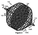
図2は、本発明による血管プラグを示す図である。 FIG. 2 is a diagram showing a blood vessel plug according to the present invention.
図3は、本発明による血管プラグを示す図である。 FIG. 3 is a diagram showing a blood vessel plug according to the present invention.
図4は、本発明による血管プラグを示す図である。 FIG. 4 is a diagram showing a blood vessel plug according to the present invention.
図5は、プッシャおよび分離機構(detachment mechanism)を示す図である。 FIG. 5 is a view showing a pusher and a detachment mechanism.
図6は、プッシャおよび分離機構を示す図である。 FIG. 6 is a diagram showing a pusher and a separating mechanism.
図7は、プッシャおよび分離機構を示す図である。 FIG. 7 is a diagram showing a pusher and a separating mechanism.
図8は、分離機構用の電力供給制御システムを示す図である。 FIG. 8 is a diagram showing a power supply control system for the separation mechanism.
図9は、血管プラグの他の実施形態を示す図である。 FIG. 9 is a view showing another embodiment of the blood vessel plug.
図10は、可撓性膜の一実施形態を示す図である。 FIG. 10 is a diagram showing an embodiment of a flexible film.
図11は、可撓性膜の一実施形態を示す図である。 FIG. 11 is a diagram showing an embodiment of a flexible film.
図12は、その内側に弾性部材を有する可撓性プラグを示す図である。 FIG. 12 is a diagram showing a flexible plug having an elastic member inside thereof.
図13は、その内側に弾性部材を有する可撓性プラグを示す図である。 FIG. 13 is a diagram showing a flexible plug having an elastic member inside thereof.
図14は、血管プラグの他の実施形態を示す図である。 FIG. 14 is a view showing another embodiment of the blood vessel plug.
図15は、血管プラグの他の実施形態を示す図である。 FIG. 15 is a diagram showing another embodiment of the blood vessel plug.
図16は、血管プラグの他の実施形態を示す図である。 FIG. 16 is a view showing another embodiment of the blood vessel plug.
図17は、血管プラグの他の実施形態を示す図である。 FIG. 17 is a diagram showing another embodiment of the blood vessel plug.
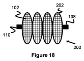
図18は、血管プラグの他の実施形態を示す図である。 FIG. 18 is a diagram showing another embodiment of the blood vessel plug.
図19は、マイクロコイルを有する血管プラグの実施形態を示す図である。 FIG. 19 is a diagram showing an embodiment of a blood vessel plug having a microcoil.
図20は、マイクロコイルを有する血管プラグの実施形態を示す図である。 FIG. 20 is a diagram showing an embodiment of a blood vessel plug having a microcoil.
図21は、血管プラグの他の実施形態を示す図である。
図22は、マイクロコイルを有する血管プラグの他の実施形態を示す図である。
FIG. 21 is a diagram showing another embodiment of the blood vessel plug.
FIG. 22 is a diagram showing another embodiment of a blood vessel plug having a micro coil.
添付図面を照し、本発明の具体的な実施形態を説明する。しかしながら、本発明は、多くの異なる形態で具現化されてもよく、本明細書に記載される実施形態に限定されるものと解釈されるべきではない。むしろ、これらの実施形態は、本開示が、完全および完成したものとなり、本発明の範囲を当業者に完全に伝えるように提供される。添付図面に図示される実施形態の詳細な説明において使用される専門用語は、本発明を限定するものとして意図されない。図面中、類似の番号は、類似の要素を示す。 Specific embodiments of the present invention will be described with reference to the accompanying drawings. However, the present invention may be embodied in many different forms and should not be construed as limited to the embodiments set forth herein. Rather, these embodiments are provided so that this disclosure will be thorough and complete, and will fully convey the scope of the invention to those skilled in the art. The terminology used in the detailed description of the embodiments illustrated in the accompanying drawings is not intended to limit the invention. In the drawings, like numbers indicate like elements.
血管プラグは血管系における様々な閉塞目的のために使用される。これらのプラグ(閉塞栓)は一般に血管の形状または血管の異常部分に適合し、それによって標的領域を介するまたは標的領域への血流を閉塞および防止する。プラグは、動脈瘤、左心耳、心房中隔欠損、瘻孔、卵円孔開存、動脈管開存および塞栓を含む様々な状態を治療するために使用することができる。すなわち、プラグは、神経血管系(neuro−vasculature)および末梢血管系における様々な閉塞目的に使用することができる。 Vascular plugs are used for various occlusion purposes in the vascular system. These plugs generally conform to the shape of the blood vessel or an abnormal portion of the blood vessel, thereby occluding and preventing blood flow through or to the target area. The plugs can be used to treat a variety of conditions including aneurysms, left atrial appendages, atrial septal defects, fistulas, patent foramen ovale, patent ductus arteriosus and embolisms. That is, the plugs can be used for various occlusion purposes in the neuro-vasculature and peripheral vasculature.
プラグは、標的空間を充填するというよりは、標的空間の形状に適合してより速い閉塞を促進するので、通常、塞栓コイルのような他の閉塞デバイスよりも速い閉塞を提供する。血管プラグは、標的空間を充填するというよりは、標的空間に適合するように意図されているので、通常、他の閉塞デバイス(塞栓コイル等)よりも大きい。他の閉塞デバイスと比較して、より大きなこのプロファイルは、供給性の問題を生じさせることがある。したがって、プラグを標的治療部位に効果的に供給するために、血管プラグは、迅速な閉塞の必要性と供給の容易さの必要性とのバランスをとる必要がある。 The plug usually conforms to the shape of the target space and promotes faster occlusion rather than filling the target space, and thus typically provides a faster occlusion than other occlusion devices such as embolic coils. Vascular plugs are usually larger than other occlusive devices (such as embolic coils) because they are intended to fit into the target space rather than fill it. This larger profile compared to other occlusion devices can give rise to deliverability problems. Therefore, in order to effectively deliver the plug to the target treatment site, the vascular plug must balance the need for rapid occlusion with the need for ease of delivery.
図1〜図8は、プッシャ112の先端に接続され、カテーテル113を介して患者内の所望の標的位置までプラグ100を前進させることを可能にする血管プラグ100の様々な態様を示す。血管プラグ100のメッシュ部102が拡張される時、可撓性膜104もまたメッシュ部102の内側で拡張され、標的位置に遮断部(blockage)または障壁(barrier)を形成する。
1-8 show various aspects of a
メッシュ部102は、(例えば、カテーテル113の内側に配置された時の)長尺の圧縮された円筒形状から、長手方向に短くかつほぼ球形の拡張形状へ拡張する。メッシュ部102のワイヤは、ニチノールワイヤ、コバルト‐クロムワイヤ、ステンレス鋼ワイヤ、またはそれらの組合せから形成することができる。一例では、メッシュ部102は、約0.0008インチ〜0.005インチの範囲の直径を有する48〜144本のニチノールワイヤから構成される。任意の選択として、1つ以上の放射線不透過性ワイヤを使用してメッシュ部102を形成し、治療中の血管プラグ100の視覚化をさらに向上させることができる。
The
メッシュ部102の先端は、先端キャップ部材108で終端となり、メッシュ部102の基端は、基端キャップ部材110で終端となる。これらのキャップ部材108および110は、メッシュ部のワイヤを結合することによって、ワイヤを個別の金属キャップに溶接することによって、金属キャップ部材をワイヤに圧着することによって、または接着剤を使用して個別のキャップをワイヤに取り付けることによって形成することができる。好ましくは、これらのキャップ部材108および110は、治療中に視覚的マーカーとして用いられるように、放射線不透過性材料から構成され得る。
The front end of the
可撓性膜104は、膜として記載されているが、広げたり、まっすぐにしたり、伸すことができる任意の材料、または他の方法で、拡大領域、好ましくは平面領域へ拡張することができる任意の材料であり得る。可撓性膜104は、生体適合性であり、好ましくは患者における血栓形成反応(thrombogenic response)を増大させる種々の可撓性材料から構成され得る。例えば、ポリエチレンテレフタレート(PET)または延伸ポリテトラフルオロエチレン(ePTFE)を使用することができる。別の具体例では、PETとePTFEの複合物を使用することができる。別の例では、可撓性膜104は、スパッタリングまたは真空蒸着によって形成されたもの等の金属薄膜から構成することができる。
Although the
可撓性膜104は、メッシュ部102の空洞内に配置された支持フレーム106によって支持されている。支持フレーム106は、拡張したメッシュ部102の最大内径領域と同様のサイズの直径に拡張する円形のリング部106Cを備える。また、リング部106Cは、リング部106Cの平面がメッシュ部の基端と先端との間の軸(例えば、キャップ108とキャップ110との間の軸)に対してほぼ直角となるように配向している。この配向は、可撓性膜104が、メッシュ部102の空洞を横切ってほぼ完全に拡張し、血管プラグ100の基端と先端との間の患者からの流体の通過を遮断することを可能にする。
The
可撓性膜104は、可撓性膜104の表面、リング部106Cのワイヤの周囲、およびそれ自体の裏面にラミネート層を形成することよって、リング部106Cに固定することができる。例えば、可撓性膜104は、PETで最初に形成され、ePTFEの層がPET層およびリング部106Cを覆うように配置または積層される。あるいは、可撓性膜104は、金属ワイヤまたはポリマー繊維を用いてリング部106Cに縫合されてもよい。別の代替的な実施形態では、接着剤が取付目的で使用されてもよい。さらに別の代替的な実施形態では、可撓性膜104は、メッシュ部102のワイヤに直接縫合または接合されてもよい。
The
リング部106Cは、先端支持アーム106Aおよび基端支持アーム106Bによって支持されることが好ましい。先端支持アーム106Aは、その先端で先端キャップ部材108に接続され、軸方向に延在し、メッシュ部102の中心近傍で径方向外向きに湾曲し、最終的にリング部106Cに接続される。同様に、基端支持アーム106Bは、その基端で基端キャップ部材110に接続され、軸方向に延在し、メッシュ部102の中心近傍で径方向外向きに湾曲し、最終的にリング部106Cに接続される。先端支持アーム106Aは、基端支持アーム106Bの接続点と正反対の位置でリング部106Cに接続されてもよい。他の実施形態では、複数の支持アームが、同様に、リング部106Cへ接続されてもよい。例えば、2、3、4または5つの支持アームが、リング部106Cの基端側および先端側の両方に備えられていてもよい。
The
図5〜図8に示されるように、血管プラグ100は、ヒーターコイル114を介して、プッシャ112から分離可能である。ヒーターコイル114は、プッシャ112の先端にあり、係留フィラメント(tether filament)116を切断する。具体的には、係留フィラメント116は、プッシャ112(例えば構造コイル(structural coil)122)に接続され、ヒーターコイル114の内部を通過し、基端キャップ110の通路を介して、メッシュ部102の中に入る。係留フィラメント116の先端は、結び目116Aに結び付けることができ、および/または接着剤によって血管プラグ100内に固定することができる。ヒーターが作動すると、係留フィラメント116が切断され、血管プラグ100がプッシャ112から解放される。
As shown in FIGS. 5-8, the
ヒーターコイル114は、プッシャ112の基端へ延在するコアワイヤ124の先端に、プッシャ112の先端において固定されている。第1のワイヤ118が位置118Aにおいてヒーターコイル114の先端に半田付けされ、第2のワイヤ120が位置120Aにおいてヒーターコイル114の基端に半田付けされる。これにより、電力が選択的に供給され、熱を発生させる。
The
図7に最もよく示されるように、ワイヤ118、120は、プッシャ112の基端へと、外側管状層126、128内で基端側に延在する。第1のワイヤ118は先端電気接点部130Aに固定され、第2のワイヤ120はコアワイヤ124に接続され、コアワイヤ124は最終的に中間電気接点部130Bに接続される。これらの接点部は、(例えば、絶縁スペーサ132を用いて)さらに電気的に絶縁され、意図しない短絡を防止する。したがって、先端電気接点部130Aおよび中間電気接点部130Bに電力を印加することによって、電気的に活性な回路を形成することができる。
As best shown in FIG. 7, the
プッシャ112の基端を電力制御供給ユニット134の差込口(passage)134Aに挿入することによって、接点部130Aおよび130Bに電力を供給することができる。好ましくは、ユニットは、ボタン134Bまたは類似のユーザインターフェース制御部を備え、所望の時間に電力を有効にする。任意の選択として、プッシャ112は、ユニット134により使用可能な基端接点部130Cを備え、プッシャ112が差込口134Aに適切に設置されているかどうかを判断することができる。同様の分離システムおよび/または変形例は、US8182506号公報、US2006‐0200192号公報、US2010‐0268204号公報、US2011‐0301686号公報、US2015‐0289879号公報、US2015‐1073772号公報およびUS2015‐0173773号公報に見出すことができる。それらの全てが、参照により組み込まれ、この実施形態(ならびに本願における他の任意の実施形態)と共に使用することができる。
By inserting the proximal end of the
操作について、プッシャ112を内部に有するカテーテル113を、カテーテル113の先端が標的閉塞部位に隣接するまで、患者の血管または内腔内で前進させる。例えば、カテーテル113の先端は、動脈瘤の中またはその入り口に配置され得る。患者内での前進の前または挿入の前のいずれかに、電気接点部130A、130Bおよび130Cを備えるプッシャ112の基端が、供給ユニット134の差込口134Aに挿入される。
For operation, the
次に、血管プラグ100がカテーテル113の先端に露出して所望の閉塞部位(例えば、動脈瘤内または血管内)に配置されるように、プッシャ112を先端側に前進させる(または任意選択でカテーテル113を後退させる)。血管プラグ100が露出すると、メッシュ部102および可撓性膜104が拡張し、その先への体液(例えば血液)の流れを実質的に遮断する。
The
最後に、ユーザは、ボタン134Bを作動させ、プッシャ112およびヒーターコイル114を介して電力を供給する。ヒーターコイル114が加熱すると、その加熱により、血管プラグ100に接続されている係留フィラメント116が切断される。これにより、血管プラグ100がプッシャ112から解放される。最後に、プッシャ112がカテーテル113内に引き戻され、両デバイスが患者から引き出される。
Finally, the user actuates
代替的に、血管プラグ100を一時的に使用することができる。具体的には、血管プラグ100を展開し、その後、カテーテル113内に引き戻すことができる。
Alternatively, the
図9は、プラグ150およびプッシャ112の軸に対して非直角で可撓性膜104の平面を位置付けるリング部106Cを備える点を除き、前述のプラグ100とほぼ同様の血管プラグ150の他の実施形態を示す。一例では、リング部106Cの平面は、プッシャ112の軸に対して約45度の角度にある。
FIG. 9 illustrates another implementation of the
可撓性膜104は血管プラグ100内でほぼ円形状をなすが、他の形状も可能である。例えば、図10は、径方向に複数のアーム部152を有するほぼ「プラス」形状の可撓性膜152を示す。他の例では、複数のほぼ円形の支持リング部156を含む可撓性膜アセンブリ154が図11に示されている。複数の支持リング部156は、それぞれ、個別の可撓性膜158を支持している。リング部と膜は互いに部分的に重なり合ってもよく、異なる数(例えば、2、3、4、5、または6つ)のリング部と膜を使用してもよい。あるいは、各支持リング部156は、正方形、三角形、楔形または楕円形等、円形以外の形状を有してもよい。
The
本明細書に記載の血管プラグの実施形態のいずれも、メッシュ部102内に弾性部材162をさらに備え、径方向の拡張を補助することができる。例えば、図12は、先端キャップ部材108および基端キャップ部材110に接続された弾性部材162を有する血管プラグ160(可撓性膜104を有しても有さなくてもよい)を示す。血管プラグ160は、その圧縮構成(すなわちカテーテル113内)にあり、弾性部材162が引き伸ばされている。図13では、血管プラグ160がカテーテル113から解放され、弾性部材162がキャップ部材108、110を互いに近づけるように引っ張り、それによってメッシュ部を拡張させている。弾性部材162は、バネまたは伸縮性の弾性ポリマー等の弾性力を提供することができる任意の材料とすることができる。
Any of the embodiments of the vascular plug described herein can further include an
本明細書に記載のメッシュ部102のいずれも、図14の血管プラグ170に示されるように、PET繊維、ハイドロゲル繊維またはPET被覆ハイドロゲル繊維等の、メッシュに織り込まれた他の材料のストランド172をさらに備えることができる。1つの具体例では、メッシュ部102は、144本の編組ニチノールワイヤ(8本のワイヤは0.0025インチの直径であり、138本のワイヤは0.001インチの直径である)から構成され、編組ニチノールワイヤを介してオーバーアンダーパターンで縫い付けられる0.004インチのステンレス鋼ワイヤに接着された20本のPET糸が用いられる。
Any of the
本明細書に記載の実施形態のメッシュ部102は、血管プラグ100のほぼ球形の形状以外の拡張形状を有することができることを理解されたい。例えば、図15および図16は、「カップ」形状または先端側を向いた凹形状に拡張する血管プラグ180の側面断面図および上面斜視図をそれぞれ示す。支持リング部106Cおよび可撓性膜104は、メッシュ部102の内部にあるように示されているが、先端側を向いた凹領域を形成する陥没部(depression)において、メッシュ部102の外側に配置することもできる。
It should be appreciated that the
図17に示される他の例では、血管プラグ190のメッシュ部102は、比較的平らなまたは扁平の楕円形状に拡張することができる。図18に示されるさらに別の例では、血管プラグ200は、複数(例えば、2、3、4、5、6つ)の軸方向に整列した電球形状202に拡張し、これは、好ましくは単一の連続的なメッシュ部102からなるように熱成形される。可撓性膜104は、任意の電球部202内、全ての電球部202内、または任意の組合せの電球部202内に固定することができる。
In another example shown in FIG. 17, the
本明細書に開示される実施形態のいずれも、塞栓マイクロコイル212(あるいは、液体塞栓材料またはPET繊維等の他の塞栓材料)を様々な場所に展開するようにさらに適合させることができる。例えば、図19は、前述のプラグ100とほぼ同様の血管プラグ210の実施形態を示す。しかし、プッシャ112および基端キャップ110は、それを介してマイクロコイル212をメッシュ部102の基端内部へ押込み可能な通路を内部に備えることができる(プッシャ112はカテーテルとてもよい)。追加のマイクロコイル212は、遮断部をさらに強化し得る。
Any of the embodiments disclosed herein can be further adapted to deploy embolic microcoil 212 (or other embolic material such as liquid embolic material or PET fibers) at various locations. For example, FIG. 19 illustrates an embodiment of a
図20に示される別の例では、血管プラグ220は、基端キャップ部材110と先端キャップ部材108との間に通路222を備え、マイクロコイル212がプラグ220の先端側に押し込まれることを可能にする。この例では、メッシュ部102は、先端側に向いている凹形状をなし、そこにマイクロコイル212が配置されている。
In another example shown in FIG. 20, the
図21に示される別の例では、血管プラグ230は可撓性膜104を欠いており、マイクロコイル212がメッシュ部102の内部空間全体に押し込まれることを可能にする。
In another example shown in FIG. 21, the
マイクロコイル212は、三次元の二次的形状が付与され、非制限時に曲線形状、コイル形状、および類似の形状をなすことができる。これらの二次的形状は、治療部位の周囲にフレームを形成するのに一般的に有用であり、その後、より小さなコイルを使用して治療部位を充填することができる。他の実施形態では、非複雑形状の塞栓コイルを利用してもよい。一例では、マイクロコイル212は、最大値が約0.023インチである直径の一次巻回体(これは供給カテーテル内での制限時のコイルの長尺形状である)を有する。これにより、内径が約0.027インチまでのカテーテル(またはマイクロコイルの通路を有するプッシャ112)内での使用を可能にする。二次(供給)巻回体のサイズ範囲は、約2mmから約20mmの間であってよい。任意選択で、マイクロコイル212は、ハイドロゲルを用いて、具体的には所定のpH(例えば、血液のpH)の流体との接触で拡張するpH反応性ハイドロゲル(pH−reactive hydrogel)を用いて、コーティングまたは含浸され得る。
The
図22は、基端キャップ部材108と先端キャップ部材110との間に延在する複数の湾曲構造ワイヤ244を有する血管プラグ240の他の実施形態を示す。可撓性膜242は、構造ワイヤ244を被覆するようにまたはその下に接続されており、スパッタリングまたは真空蒸着によって形成されたもの等の金属薄膜から構成することができる。あるいは、可撓性膜242は、PET等のポリマーまたはメッシュから構成することができる。任意選択で、血管プラグ244は、可撓性膜の内部にマイクロコイル212を供給するように構成される。
FIG. 22 illustrates another embodiment of a
本発明を特定の実施形態および用途に関して説明してきたが、当業者であれば、この教示に照らして、特許請求の範囲の精神から逸脱することなく、またはその範囲を超えることなく追加の実施形態および修正を生み出すことができる。したがって、本明細書および図面は、本発明の理解を容易にするために例として提供されるものであり、その範囲を限定するように解釈されるべきではないことを理解されたい。 Although the present invention has been described in terms of particular embodiments and uses, those skilled in the art will appreciate that additional embodiments will be apparent to those of ordinary skill in the art in light of this teaching without departing from, or exceeding, the spirit of the claims. And can produce modifications. Therefore, it should be understood that this specification and the drawings are provided as examples for facilitating the understanding of the present invention and should not be construed as limiting the scope thereof.
Claims (18)
長尺のプッシャと、With a long pusher,
前記長尺のプッシャの先端に固定され、カテーテル内での制限時に径方向に圧縮した構成を有し、非制限時に径方向に拡張した構成を有するメッシュ部と、A mesh portion fixed to the tip of the long pusher, having a configuration that is compressed in the radial direction when restricted within the catheter, and having a configuration that is expanded in the radial direction when not restricted,
前記メッシュ部の内部の基端部にわたる基端支持アームと、前記メッシュ部の前記内部の先端部にわたる先端支持アームと、前記基端支持アームおよび前記先端支持アームは、前記メッシュ部の前記内部にリング部を形成し、The proximal support arm extending over the proximal end inside the mesh portion, the distal end support arm extending over the distal end inside the mesh portion, the proximal end support arm and the distal end support arm are located inside the mesh portion. Forming a ring part,
前記リング部に固定され、前記メッシュ部が前記径方向に拡張した構成をとる際に径方向に拡張した構成をとることにより、前記メッシュ部を介した血液の通過を制限する膜と、を含むことを特徴とする血管プラグ。A membrane that is fixed to the ring portion and that restricts the passage of blood through the mesh portion by adopting a structure that is expanded in the radial direction when the mesh portion is expanded in the radial direction. A blood vessel plug characterized in that
長尺のプッシャと、With a long pusher,
前記長尺のプッシャの先端に固定され、カテーテル内での制限時に径方向に圧縮した構成を有し、非制限時に径方向に拡張した構成を有するメッシュ部と、A mesh portion that is fixed to the tip of the long pusher, has a configuration that is compressed in the radial direction when restricted in the catheter, and has a configuration that is expanded in the radial direction when not restricted,
前記メッシュ部の内部の基端部にわたる基端支持アームと、前記メッシュ部の前記内部の先端部にわたる先端支持アームと、前記基端支持アームおよび前記先端支持アームは、前記メッシュ部の前記内部にリング部を形成し、ここで、前記リング部が、前記長尺のプッシャの軸に対して非直角で、前記メッシュ部の前記内部に拡張し、The proximal support arm extending over the proximal end inside the mesh portion, the distal end support arm extending over the distal end inside the mesh portion, the proximal end support arm and the distal end support arm are located inside the mesh portion. Forming a ring portion, wherein the ring portion is non-perpendicular to the axis of the elongated pusher and extends into the interior of the mesh portion;
前記リング部に固定され、前記メッシュ部が前記径方向に拡張した構成をとる際に径方向に拡張した構成をとることにより、前記メッシュ部を介した血液の通過を制限する膜と、を含むことを特徴とする血管プラグ。A membrane that is fixed to the ring portion and that restricts the passage of blood through the mesh portion by adopting a structure that is expanded in the radial direction when the mesh portion is expanded in the radial direction. A blood vessel plug characterized in that
長尺のプッシャと、With a long pusher,
前記長尺のプッシャの先端に固定され、カテーテル内での制限時に径方向に圧縮した構成を有し、非制限時に径方向に拡張した構成を有するメッシュ部と、A mesh portion that is fixed to the tip of the long pusher, has a configuration that is compressed in the radial direction when restricted in the catheter, and has a configuration that is expanded in the radial direction when not restricted,
前記メッシュ部の内部の基端部にわたる基端支持アームと、前記メッシュ部の前記内部の先端部にわたる先端支持アームと、前記基端支持アームおよび前記先端支持アームは、前記メッシュ部の前記内部にリング部を形成し、A proximal end support arm extending over a proximal end portion inside the mesh portion, a distal end support arm extending over the distal end portion inside the mesh portion, the proximal end support arm and the distal end support arm are disposed inside the mesh portion. Forming a ring part,
前記リング部に固定され、前記メッシュ部が前記径方向に拡張した構成をとる際に、前記長尺のプッシャの軸に対して非直角で、径方向に拡張した構成をとることにより、前記メッシュ部を介した血液の通過を制限する膜と、を含むことを特徴とする血管プラグ。The mesh is fixed to the ring portion, and when the mesh portion is expanded in the radial direction, the mesh is non-perpendicular to the axis of the elongated pusher and expanded in the radial direction. A membrane for restricting the passage of blood through the part, and a vascular plug.
Applications Claiming Priority (3)
| Application Number | Priority Date | Filing Date | Title |
|---|---|---|---|
| US201662348729P | 2016-06-10 | 2016-06-10 | |
| US62/348,729 | 2016-06-10 | ||
| PCT/US2017/036872 WO2017214577A1 (en) | 2016-06-10 | 2017-06-09 | Vessel occluder |
Related Child Applications (1)
| Application Number | Title | Priority Date | Filing Date |
|---|---|---|---|
| JP2020136160A Division JP7005710B2 (en) | 2016-06-10 | 2020-08-12 | Vascular occluder |
Publications (3)
| Publication Number | Publication Date |
|---|---|
| JP2019519304A JP2019519304A (en) | 2019-07-11 |
| JP2019519304A5 JP2019519304A5 (en) | 2020-07-27 |
| JP6750045B2 true JP6750045B2 (en) | 2020-09-02 |
Family
ID=60572035
Family Applications (4)
| Application Number | Title | Priority Date | Filing Date |
|---|---|---|---|
| JP2018564798A Active JP6750045B2 (en) | 2016-06-10 | 2017-06-09 | Vascular occluder |
| JP2020136160A Active JP7005710B2 (en) | 2016-06-10 | 2020-08-12 | Vascular occluder |
| JP2022000635A Active JP7338826B2 (en) | 2016-06-10 | 2022-01-05 | vascular occluder |
| JP2023138441A Pending JP2023169181A (en) | 2016-06-10 | 2023-08-09 | Blood vessel occluder |
Family Applications After (3)
| Application Number | Title | Priority Date | Filing Date |
|---|---|---|---|
| JP2020136160A Active JP7005710B2 (en) | 2016-06-10 | 2020-08-12 | Vascular occluder |
| JP2022000635A Active JP7338826B2 (en) | 2016-06-10 | 2022-01-05 | vascular occluder |
| JP2023138441A Pending JP2023169181A (en) | 2016-06-10 | 2023-08-09 | Blood vessel occluder |
Country Status (5)
| Country | Link |
|---|---|
| US (3) | US10470773B2 (en) |
| EP (2) | EP3912569A1 (en) |
| JP (4) | JP6750045B2 (en) |
| CN (2) | CN111904522B (en) |
| WO (1) | WO2017214577A1 (en) |
Families Citing this family (36)
| Publication number | Priority date | Publication date | Assignee | Title |
|---|---|---|---|---|
| US10327781B2 (en) | 2012-11-13 | 2019-06-25 | Covidien Lp | Occlusive devices |
| US9265512B2 (en) | 2013-12-23 | 2016-02-23 | Silk Road Medical, Inc. | Transcarotid neurovascular catheter |
| US10426497B2 (en) | 2015-07-24 | 2019-10-01 | Route 92 Medical, Inc. | Anchoring delivery system and methods |
| ES2932764T3 (en) | 2015-02-04 | 2023-01-26 | Route 92 Medical Inc | Rapid Aspiration Thrombectomy System |
| US11065019B1 (en) | 2015-02-04 | 2021-07-20 | Route 92 Medical, Inc. | Aspiration catheter systems and methods of use |
| EP3419528B1 (en) | 2016-02-24 | 2023-06-07 | Incept, LLC | Enhanced flexibility neurovascular catheter |
| JP6750045B2 (en) * | 2016-06-10 | 2020-09-02 | テルモ株式会社 | Vascular occluder |
| US10576099B2 (en) | 2016-10-21 | 2020-03-03 | Covidien Lp | Injectable scaffold for treatment of intracranial aneurysms and related technology |
| CN110022789B (en) * | 2016-11-23 | 2022-07-12 | 霍罗吉克公司 | Biopsy site marker |
| JP7264581B2 (en) | 2017-01-06 | 2023-04-25 | インセプト、リミテッド、ライアビリティ、カンパニー | Antithrombotic coating for aneurysm treatment devices |
| EP3568186B1 (en) | 2017-01-10 | 2022-09-14 | Route 92 Medical, Inc. | Aspiration catheter systems |
| US11191547B2 (en) | 2018-01-26 | 2021-12-07 | Syntheon 2.0, LLC | Left atrial appendage clipping device and methods for clipping the LAA |
| CN110215252B (en) * | 2018-03-02 | 2021-12-03 | 上海微创医疗器械(集团)有限公司 | Occluder and medical instrument |
| US11109867B2 (en) * | 2018-03-16 | 2021-09-07 | Boston Scientific Scimed, Inc. | Devices and methods for vein closure |
| CN112203593A (en) | 2018-05-01 | 2021-01-08 | 因赛普特有限责任公司 | Device and method for removing occlusive material from an intravascular site |
| US11395665B2 (en) | 2018-05-01 | 2022-07-26 | Incept, Llc | Devices and methods for removing obstructive material, from an intravascular site |
| JP2021523793A (en) | 2018-05-17 | 2021-09-09 | ルート92メディカル・インコーポレイテッドRoute 92 Medical, Inc. | Suction catheter system and how to use |
| US11382632B2 (en) * | 2018-06-27 | 2022-07-12 | Boston Scientific Scimed, Inc. | Vascular occlusion device |
| US11471582B2 (en) | 2018-07-06 | 2022-10-18 | Incept, Llc | Vacuum transfer tool for extendable catheter |
| US11517335B2 (en) | 2018-07-06 | 2022-12-06 | Incept, Llc | Sealed neurovascular extendable catheter |
| CN110960279B (en) * | 2018-09-29 | 2023-06-16 | 上海佐心医疗科技有限公司 | Left auricle plugging device and left auricle plugging system |
| US11317921B2 (en) * | 2019-03-15 | 2022-05-03 | Sequent Medical, Inc. | Filamentary devices for treatment of vascular defects |
| US11766539B2 (en) | 2019-03-29 | 2023-09-26 | Incept, Llc | Enhanced flexibility neurovascular catheter |
| US10925615B2 (en) | 2019-05-03 | 2021-02-23 | Syntheon 2.0, LLC | Recapturable left atrial appendage clipping device and methods for recapturing a left atrial appendage clip |
| CN114340516A (en) * | 2019-08-30 | 2022-04-12 | 波士顿科学医学有限公司 | Left atrial appendage implant with sealing disk |
| CN113347916A (en) | 2019-10-15 | 2021-09-03 | 因普瑞缇夫护理公司 | System and method for multivariate stroke detection |
| EP4054440A1 (en) * | 2019-11-04 | 2022-09-14 | Covidien LP | Devices, systems, and methods for treatment of intracranial aneurysms |
| JP2023507553A (en) | 2019-12-18 | 2023-02-24 | インパラティブ、ケア、インク. | Methods and systems for treating venous thromboembolism |
| US11259821B2 (en) | 2019-12-18 | 2022-03-01 | Imperative Care, Inc. | Aspiration system with accelerated response |
| US11633272B2 (en) | 2019-12-18 | 2023-04-25 | Imperative Care, Inc. | Manually rotatable thrombus engagement tool |
| CN113116405B (en) * | 2019-12-30 | 2022-07-05 | 先健科技(深圳)有限公司 | Plugging device |
| AU2021235887A1 (en) | 2020-03-10 | 2022-09-08 | Imperative Care, Inc. | Enhanced flexibility neurovascular catheter |
| US11903589B2 (en) | 2020-03-24 | 2024-02-20 | Boston Scientific Scimed, Inc. | Medical system for treating a left atrial appendage |
| US11207497B1 (en) | 2020-08-11 | 2021-12-28 | Imperative Care, Inc. | Catheter with enhanced tensile strength |
| CN113143378B (en) * | 2021-04-15 | 2023-03-17 | 湖南思脉医疗器械有限公司 | Sliding sheath tube capable of plugging artery and vein |
| WO2023240006A1 (en) * | 2022-06-08 | 2023-12-14 | Terumo Corporation | Vascular occlusion device |
Family Cites Families (57)
| Publication number | Priority date | Publication date | Assignee | Title |
|---|---|---|---|---|
| US5499995C1 (en) * | 1994-05-25 | 2002-03-12 | Paul S Teirstein | Body passageway closure apparatus and method of use |
| DE19604817C2 (en) | 1996-02-09 | 2003-06-12 | Pfm Prod Fuer Die Med Ag | Device for closing defect openings in the human or animal body |
| US6592617B2 (en) | 1996-04-30 | 2003-07-15 | Boston Scientific Scimed, Inc. | Three-dimensional braided covered stent |
| US5980554A (en) | 1997-05-05 | 1999-11-09 | Micro Therapeutics, Inc. | Wire frame partial flow obstruction for aneurysm treatment |
| US6120534A (en) * | 1997-10-29 | 2000-09-19 | Ruiz; Carlos E. | Endoluminal prosthesis having adjustable constriction |
| US20100030256A1 (en) * | 1997-11-12 | 2010-02-04 | Genesis Technologies Llc | Medical Devices and Methods |
| US5925060A (en) | 1998-03-13 | 1999-07-20 | B. Braun Celsa | Covered self-expanding vascular occlusion device |
| AU756080B2 (en) | 1998-06-04 | 2003-01-02 | New York University | Endovascular thin film devices and methods for treating and preventing stroke |
| US7128073B1 (en) * | 1998-11-06 | 2006-10-31 | Ev3 Endovascular, Inc. | Method and device for left atrial appendage occlusion |
| US6428558B1 (en) | 1999-03-10 | 2002-08-06 | Cordis Corporation | Aneurysm embolization device |
| US20020169473A1 (en) | 1999-06-02 | 2002-11-14 | Concentric Medical, Inc. | Devices and methods for treating vascular malformations |
| US6632241B1 (en) | 2000-03-22 | 2003-10-14 | Endovascular Technologies, Inc. | Self-expanding, pseudo-braided intravascular device |
| US7651696B2 (en) | 2000-08-25 | 2010-01-26 | Nexeon Medical Systems, Inc. | Implantable device for treating disease states and methods of using same |
| US6554849B1 (en) | 2000-09-11 | 2003-04-29 | Cordis Corporation | Intravascular embolization device |
| IL143007A0 (en) | 2001-05-07 | 2002-04-21 | Rafael Medical Technologies In | Retrievable intravascular support structures |
| US6811560B2 (en) | 2001-09-20 | 2004-11-02 | Cordis Neurovascular, Inc. | Stent aneurysm embolization method and device |
| US6638257B2 (en) | 2002-03-01 | 2003-10-28 | Aga Medical Corporation | Intravascular flow restrictor |
| CN1937976B (en) * | 2004-02-02 | 2011-12-07 | 孕体有限公司 | Enhancing tissue ingrowth for contraception |
| DE602004007555T2 (en) | 2004-02-04 | 2008-03-13 | Carag Ag | IMPLANT FOR THE OCCLUSION OF A BODY CHANNEL |
| US8747453B2 (en) | 2008-02-18 | 2014-06-10 | Aga Medical Corporation | Stent/stent graft for reinforcement of vascular abnormalities and associated method |
| US8313505B2 (en) | 2004-03-19 | 2012-11-20 | Aga Medical Corporation | Device for occluding vascular defects |
| US8777974B2 (en) | 2004-03-19 | 2014-07-15 | Aga Medical Corporation | Multi-layer braided structures for occluding vascular defects |
| US9039724B2 (en) | 2004-03-19 | 2015-05-26 | Aga Medical Corporation | Device for occluding vascular defects |
| WO2006024040A2 (en) | 2004-08-25 | 2006-03-02 | Microvention, Inc. | Thermal detachment system for implantable devices |
| US8517027B2 (en) * | 2004-09-03 | 2013-08-27 | Boston Scientific Scimed, Inc. | Reversible vessel seal |
| US7771452B2 (en) | 2005-07-12 | 2010-08-10 | Cook Incorporated | Embolic protection device with a filter bag that disengages from a basket |
| CN101002702A (en) * | 2006-01-16 | 2007-07-25 | 上海康德莱企业发展集团有限公司 | Braided blood vessel stent with external ring-net skirt |
| US8075619B2 (en) | 2006-06-13 | 2011-12-13 | Anova Corporation | Devices for disc herniation repair and methods of use |
| JP2010500915A (en) | 2006-08-17 | 2010-01-14 | エヌフォーカス ニューロメディカル, インコーポレイテッド | Aneurysm isolation device |
| WO2008074027A1 (en) | 2006-12-13 | 2008-06-19 | Biomerix Corporation | Aneurysm occlusion devices |
| US8057503B2 (en) * | 2007-01-25 | 2011-11-15 | Trinity Health-Michigan | Blood vessel occluder and method of use |
| US8308752B2 (en) | 2007-08-27 | 2012-11-13 | Cook Medical Technologies Llc | Barrel occlusion device |
| US20090082803A1 (en) | 2007-09-26 | 2009-03-26 | Aga Medical Corporation | Braided vascular devices having no end clamps |
| US8764772B2 (en) * | 2008-02-21 | 2014-07-01 | Cook Medical Technologies Llc | Occlusion device |
| US20130165967A1 (en) | 2008-03-07 | 2013-06-27 | W.L. Gore & Associates, Inc. | Heart occlusion devices |
| JP5391407B2 (en) * | 2008-04-03 | 2014-01-15 | クック・メディカル・テクノロジーズ・リミテッド・ライアビリティ・カンパニー | Self-cleaning device, system and method of use thereof |
| AU2009239424B9 (en) | 2008-04-21 | 2014-10-09 | Covidien Lp | Braid-ball embolic devices and delivery systems |
| KR101502003B1 (en) | 2008-07-08 | 2015-03-12 | 엘지전자 주식회사 | Mobile terminal and method for inputting a text thereof |
| JP5608731B2 (en) | 2009-04-15 | 2014-10-15 | マイクロベンション インコーポレイテッド | Implant delivery system |
| AU2010315106A1 (en) * | 2009-11-05 | 2012-05-17 | Sequent Medical Inc. | Multiple layer filamentary devices or treatment of vascular defects |
| US20110202085A1 (en) * | 2009-11-09 | 2011-08-18 | Siddharth Loganathan | Braid Ball Embolic Device Features |
| CA2795740C (en) | 2010-04-14 | 2018-03-13 | Microvention, Inc. | Implant delivery device |
| WO2012166804A1 (en) * | 2011-06-03 | 2012-12-06 | Reverse Medical Corporation | Embolic implant and method of use |
| WO2013138789A1 (en) * | 2012-03-16 | 2013-09-19 | Microvention, Inc. | Stent and stent delivery device |
| CN104394776B (en) * | 2012-06-11 | 2017-12-08 | E-佩森公司 | Vascular occlusion device and method |
| CN203042352U (en) * | 2012-12-26 | 2013-07-10 | 郑宏 | Plugging device for left aurcle and cardiovascular abnormal channel |
| US10342546B2 (en) | 2013-01-14 | 2019-07-09 | Microvention, Inc. | Occlusive device |
| WO2014201105A2 (en) * | 2013-06-11 | 2014-12-18 | ProMed, Inc. | Systems and methods for improved vessel access closure |
| US10010328B2 (en) * | 2013-07-31 | 2018-07-03 | NeuVT Limited | Endovascular occlusion device with hemodynamically enhanced sealing and anchoring |
| US20150080945A1 (en) | 2013-09-18 | 2015-03-19 | W. L. Gore Associates, Inc. | Partial Circumferential Stent with Non-Radial Apposition |
| US9696225B2 (en) | 2013-10-23 | 2017-07-04 | Link Engineering Company | Low friction tailstock assembly |
| US10398441B2 (en) * | 2013-12-20 | 2019-09-03 | Terumo Corporation | Vascular occlusion |
| WO2015095798A1 (en) | 2013-12-20 | 2015-06-25 | Microvention, Inc. | Catheter system |
| EP4151164A1 (en) * | 2014-04-11 | 2023-03-22 | Microvention, Inc. | Implant delivery system |
| US9289280B2 (en) * | 2014-06-19 | 2016-03-22 | The Regents Of The University Of California | Bidirectional vascular filter and method of use |
| CN107427303A (en) * | 2015-02-18 | 2017-12-01 | 波士顿科学国际有限公司 | Vasoocclusive device |
| JP6750045B2 (en) * | 2016-06-10 | 2020-09-02 | テルモ株式会社 | Vascular occluder |
-
2017
- 2017-06-09 JP JP2018564798A patent/JP6750045B2/en active Active
- 2017-06-09 CN CN202010841945.1A patent/CN111904522B/en active Active
- 2017-06-09 WO PCT/US2017/036872 patent/WO2017214577A1/en unknown
- 2017-06-09 EP EP21181018.9A patent/EP3912569A1/en active Pending
- 2017-06-09 EP EP17811127.4A patent/EP3468479B1/en active Active
- 2017-06-09 CN CN201780048053.2A patent/CN109688940B/en active Active
- 2017-06-09 US US15/619,296 patent/US10470773B2/en active Active
-
2019
- 2019-09-26 US US16/584,722 patent/US11583287B2/en active Active
-
2020
- 2020-08-12 JP JP2020136160A patent/JP7005710B2/en active Active
-
2022
- 2022-01-05 JP JP2022000635A patent/JP7338826B2/en active Active
-
2023
- 2023-01-23 US US18/157,930 patent/US20230149024A1/en active Pending
- 2023-08-09 JP JP2023138441A patent/JP2023169181A/en active Pending
Also Published As
| Publication number | Publication date |
|---|---|
| US11583287B2 (en) | 2023-02-21 |
| JP2022062006A (en) | 2022-04-19 |
| US20230149024A1 (en) | 2023-05-18 |
| JP2019519304A (en) | 2019-07-11 |
| CN111904522A (en) | 2020-11-10 |
| CN111904522B (en) | 2023-06-16 |
| CN109688940A (en) | 2019-04-26 |
| EP3468479A1 (en) | 2019-04-17 |
| JP2023169181A (en) | 2023-11-29 |
| EP3468479B1 (en) | 2021-08-04 |
| CN109688940B (en) | 2020-09-22 |
| WO2017214577A1 (en) | 2017-12-14 |
| JP7338826B2 (en) | 2023-09-05 |
| EP3468479A4 (en) | 2020-02-19 |
| JP7005710B2 (en) | 2022-01-24 |
| US20170354421A1 (en) | 2017-12-14 |
| JP2020203094A (en) | 2020-12-24 |
| US10470773B2 (en) | 2019-11-12 |
| US20200038034A1 (en) | 2020-02-06 |
| EP3912569A1 (en) | 2021-11-24 |
Similar Documents
| Publication | Publication Date | Title |
|---|---|---|
| JP6750045B2 (en) | Vascular occluder | |
| US11723667B2 (en) | Filamentary devices for treatment of vascular defects | |
| US20230338035A1 (en) | Filamentary devices for treatment of vascular defects | |
| US20230270441A1 (en) | Devices for therapeutic vascular procedures | |
| US20200281603A1 (en) | Filamentary devices for treatment of vascular defects | |
| US20200000477A1 (en) | Embolization Plug | |
| EP3061402B1 (en) | Occlusive devices with anchoring means | |
| CA2532112C (en) | Tubular patent foramen ovale (pfo) closure device with catch system | |
| US20120283768A1 (en) | Method and apparatus for the treatment of large and giant vascular defects | |
| US20180221030A1 (en) | Devices and Methods for Treatment of Endovascular and Non-Endovascular Defects in Humans Using Tandem Embolization Devices | |
| US20180317933A1 (en) | Devices and Methods for Treatment of Endovascular and Non-Endovascular Defects in Humans |
Legal Events
| Date | Code | Title | Description |
|---|---|---|---|
| A521 | Request for written amendment filed |
Free format text: JAPANESE INTERMEDIATE CODE: A523 Effective date: 20200605 |
|
| A621 | Written request for application examination |
Free format text: JAPANESE INTERMEDIATE CODE: A621 Effective date: 20200605 |
|
| A871 | Explanation of circumstances concerning accelerated examination |
Free format text: JAPANESE INTERMEDIATE CODE: A871 Effective date: 20200605 |
|
| A975 | Report on accelerated examination |
Free format text: JAPANESE INTERMEDIATE CODE: A971005 Effective date: 20200702 |
|
| TRDD | Decision of grant or rejection written | ||
| A01 | Written decision to grant a patent or to grant a registration (utility model) |
Free format text: JAPANESE INTERMEDIATE CODE: A01 Effective date: 20200714 |
|
| A61 | First payment of annual fees (during grant procedure) |
Free format text: JAPANESE INTERMEDIATE CODE: A61 Effective date: 20200812 |
|
| R150 | Certificate of patent or registration of utility model |
Ref document number: 6750045 Country of ref document: JP Free format text: JAPANESE INTERMEDIATE CODE: R150 |
|
| R250 | Receipt of annual fees |
Free format text: JAPANESE INTERMEDIATE CODE: R250 |