JP2013501414A - Method of crosstalk correction for three-dimensional (3D) projection - Google Patents
Method of crosstalk correction for three-dimensional (3D) projection Download PDFInfo
- Publication number
- JP2013501414A JP2013501414A JP2012523053A JP2012523053A JP2013501414A JP 2013501414 A JP2013501414 A JP 2013501414A JP 2012523053 A JP2012523053 A JP 2012523053A JP 2012523053 A JP2012523053 A JP 2012523053A JP 2013501414 A JP2013501414 A JP 2013501414A
- Authority
- JP
- Japan
- Prior art keywords
- image
- crosstalk
- pixel
- projection
- images
- Prior art date
- Legal status (The legal status is an assumption and is not a legal conclusion. Google has not performed a legal analysis and makes no representation as to the accuracy of the status listed.)
- Pending
Links
Images


Classifications
-
- H—ELECTRICITY
- H04—ELECTRIC COMMUNICATION TECHNIQUE
- H04N—PICTORIAL COMMUNICATION, e.g. TELEVISION
- H04N13/00—Stereoscopic video systems; Multi-view video systems; Details thereof
- H04N13/10—Processing, recording or transmission of stereoscopic or multi-view image signals
- H04N13/106—Processing image signals
- H04N13/122—Improving the 3D impression of stereoscopic images by modifying image signal contents, e.g. by filtering or adding monoscopic depth cues
- H04N13/125—Improving the 3D impression of stereoscopic images by modifying image signal contents, e.g. by filtering or adding monoscopic depth cues for crosstalk reduction
-
- H—ELECTRICITY
- H04—ELECTRIC COMMUNICATION TECHNIQUE
- H04N—PICTORIAL COMMUNICATION, e.g. TELEVISION
- H04N13/00—Stereoscopic video systems; Multi-view video systems; Details thereof
- H04N13/10—Processing, recording or transmission of stereoscopic or multi-view image signals
- H04N13/106—Processing image signals
- H04N13/122—Improving the 3D impression of stereoscopic images by modifying image signal contents, e.g. by filtering or adding monoscopic depth cues
-
- H—ELECTRICITY
- H04—ELECTRIC COMMUNICATION TECHNIQUE
- H04N—PICTORIAL COMMUNICATION, e.g. TELEVISION
- H04N13/00—Stereoscopic video systems; Multi-view video systems; Details thereof
- H04N13/10—Processing, recording or transmission of stereoscopic or multi-view image signals
- H04N13/106—Processing image signals
- H04N13/133—Equalising the characteristics of different image components, e.g. their average brightness or colour balance
-
- H—ELECTRICITY
- H04—ELECTRIC COMMUNICATION TECHNIQUE
- H04N—PICTORIAL COMMUNICATION, e.g. TELEVISION
- H04N13/00—Stereoscopic video systems; Multi-view video systems; Details thereof
- H04N13/10—Processing, recording or transmission of stereoscopic or multi-view image signals
- H04N13/189—Recording image signals; Reproducing recorded image signals
-
- H—ELECTRICITY
- H04—ELECTRIC COMMUNICATION TECHNIQUE
- H04N—PICTORIAL COMMUNICATION, e.g. TELEVISION
- H04N13/00—Stereoscopic video systems; Multi-view video systems; Details thereof
- H04N13/30—Image reproducers
- H04N13/363—Image reproducers using image projection screens
-
- H—ELECTRICITY
- H04—ELECTRIC COMMUNICATION TECHNIQUE
- H04N—PICTORIAL COMMUNICATION, e.g. TELEVISION
- H04N13/00—Stereoscopic video systems; Multi-view video systems; Details thereof
- H04N13/30—Image reproducers
- H04N13/398—Synchronisation thereof; Control thereof
Landscapes
- Engineering & Computer Science (AREA)
- Multimedia (AREA)
- Signal Processing (AREA)
- Testing, Inspecting, Measuring Of Stereoscopic Televisions And Televisions (AREA)
- Projection Apparatus (AREA)
- Stereoscopic And Panoramic Photography (AREA)
- Control Of Indicators Other Than Cathode Ray Tubes (AREA)
Abstract
3次元投影用の立体画像のクロストーク補償のための方法を開示する。この方法は、差分歪みを呈する画像からのクロストーク寄与を少なくとも部分的に補償するための濃度または明るさ調整を組み込む立体画像ペアを含む立体プレゼンテーションの生成に用いることができる。A method for crosstalk compensation of stereoscopic images for three-dimensional projection is disclosed. This method can be used to generate a stereoscopic presentation that includes a stereoscopic image pair that incorporates density or brightness adjustments to at least partially compensate for crosstalk contributions from images exhibiting differential distortion.
Description
関連出願の相互参照
本出願は、両方とも参照によってその全体が本明細書に組み込まれている、2009年7月29日に出願した米国特許出願第61/229,276号"Method and System for Crosstalk Correction for 3D Projection"、および2009年11月16日に出願した米国特許出願第61/261,732号"Method and System for Crosstalk Correction for Three-Dimensional (3D) Projection"の優先権を主張する。
CROSS REFERENCE TO RELATED APPLICATIONS This application is a U.S. patent application 61 / 229,276 filed July 29, 2009, "Method and System for Crosstalk," both of which are incorporated herein by reference in their entirety. Claims "Priority for 3D Projection" and US Patent Application No. 61 / 261,732 "Method and System for Crosstalk Correction for Three-Dimensional (3D) Projection" filed on November 16, 2009.
本発明は、クロストーク補償を用いる3次元(3D)投影および立体プレゼンテーションにおいて使用するクロストーク補正のための方法に関する。 The present invention relates to a method for crosstalk correction for use in three-dimensional (3D) projection and stereo presentation with crosstalk compensation.
3次元(3D)フィルムの現在の波は、人気を博しつつあり、3Dデジタル映画投影システムの使いやすさによって可能になっている。ただし、デジタルシステムの公開速度は、一つには比較的高いコストを伴うという理由により、需要に見合うほど妥当ではない。初期の3Dフィルムシステムは、絵の構成ミス、低い明るさ、および変色を含む様々な技術的問題点を被っていたが、デジタル映画手法よりかなり安価であった。1980年代に、3Dフィルムの波が、米国およびそれ以外で示されたが、Chris Condon(特許文献1)によって設計され特許化されたレンズおよびフィルタを使用していた。Condonに対するそれ以外の改良が、Liptonなどによって特許文献2で提案された。両方の参考文献における主題は、参照によってその全体が本明細書に組み込まれている。 The current wave of 3D (3D) film is gaining popularity and is made possible by the ease of use of 3D digital cinema projection systems. However, the speed at which digital systems are published is not reasonable enough to meet demand, partly because of the relatively high costs. Early 3D film systems suffered various technical problems including picture misconfiguration, low brightness, and discoloration, but were much cheaper than digital cinema techniques. In the 1980s, 3D film waves were shown in the United States and elsewhere, but using lenses and filters designed and patented by Chris Condon. Another improvement to Condon was proposed in US Pat. The subject matter in both references is incorporated herein by reference in its entirety.
従来のシングルプロジェクタ3Dフィルムシステムは、デュアルレンズを使って、同じフィルムストリップにおいて互いの上下にレイアウトされた左眼画像および右眼画像を同時に投影する。こうした左眼画像および右眼画像は、別々に符号化され(たとえば、別々の偏光または有色フィルタによって)、スクリーンに一緒に投影され、デコーダとして作用するフィルタ眼鏡をかけている観衆によって観察され、その結果、観衆の左眼は、投影された左眼画像(以下、投影左眼画像)を主に見て、右眼は、投影右眼画像を主に見る。ただし、投影およびビューイングシステム内の1つもしくは複数の構成要素、たとえば、符号化フィルタ、復号フィルタ、または投影スクリーンなど、他の要素の欠陥により、右眼画像を投影する一定量の光が、観衆の左眼に対して可視的になる場合があり、同様に、左眼画像の投影に使われる一定量の光が、観衆の右眼に対して可視的になる場合があり、結果的にクロストークを生じる。概して、「クロストーク」は、結果として投影画像が、違う方の眼に対して可視的になる、立体投影システムにおける光漏洩の現象または挙動を指す。様々なクロストーク関連パラメータを記述するのに使われる他の用語は、たとえば、「クロストーク率」を含み、これは、たとえば、一方の眼の画像から他方の眼の画像への、百分率または分数として表される、光漏洩に関する測定可能な量を示すものであり、ディスプレイまたは投影システムの特性である。「クロストーク値」も含まれ、これは、システムによってディスプレイされる画像ペアに固有のクロストークの事例である、適切な明るさ関連単位で表される、クロストークの量を指す。どのクロストーク関連パラメータも、概してクロストーク情報と見なされ得る。 A conventional single projector 3D film system uses a dual lens to simultaneously project a left eye image and a right eye image laid out on top of each other on the same film strip. These left-eye and right-eye images are encoded separately (eg, with separate polarization or colored filters), projected together on the screen, and viewed by an audience wearing filter glasses acting as decoders, As a result, the left eye of the audience mainly sees the projected left eye image (hereinafter, the projected left eye image), and the right eye mainly sees the projected right eye image. However, due to defects in one or more components in the projection and viewing system, such as an encoding filter, a decoding filter, or a projection screen, a certain amount of light that projects the right eye image May be visible to the left eye of the audience, and similarly, a certain amount of light used to project the left eye image may be visible to the right eye of the audience, resulting in Crosstalk occurs. In general, “crosstalk” refers to the phenomenon or behavior of light leakage in a stereoscopic projection system that results in the projected image being visible to a different eye. Other terms used to describe various crosstalk related parameters include, for example, “crosstalk rate”, which is, for example, the percentage or fraction of one eye image to another eye image. , Which represents the measurable amount of light leakage, which is characteristic of the display or projection system. Also included is “crosstalk value”, which refers to the amount of crosstalk, expressed in the appropriate brightness-related units, which is an example of crosstalk inherent in image pairs displayed by the system. Any crosstalk related parameter can generally be considered crosstalk information.
立体イメージの特性である両眼視差により、オブジェクトが、左眼および右眼によって、スクリーン上で、水平方向に異なる場所に見える(また、水平隔離の度合によって、距離の知覚が決まる)。両眼視差と合成されたときのクロストークの影響は、各眼が、オブジェクトの明画像をスクリーン上の正しい場所で、同じオブジェクトの暗画像(または他方の画像より暗い)を、わずかにずれた位置で見ることにより、明画像の視覚的「エコー」または「ゴースト」が生じることである。 Due to the binocular parallax that is a characteristic of stereoscopic images, the left and right eyes make the object appear in different locations on the screen in the horizontal direction (and the distance perception determines the distance perception). The effect of crosstalk when combined with binocular parallax was that each eye slightly shifted the dark image of the same object (or darker than the other image) with the bright image of the object in the correct location on the screen Viewing in position produces a visual “echo” or “ghost” of the bright image.
さらに、こうした従来技術の「上下式」3D投影システムは、左眼と右眼との間に差分キーストーニング歪みを呈し、スクリーンの最上部および最下部で特に明らかである。この歪みにより、クロストークのある画像の位置が、単なる両眼視差を越えてさらに修正される。 Furthermore, such prior art “up and down” 3D projection systems exhibit differential keystone distortion between the left and right eyes, and are particularly evident at the top and bottom of the screen. This distortion further corrects the position of the image with crosstalk beyond the binocular parallax.
この複合効果は、観衆にとって気が散るだけでなく、眼精疲労も引き起こす場合があり、3Dプレゼンテーションを損なわせる。クロストークは、符号化または復号フィルタおよび他の要素(たとえば、スクリーン)が、理想的なプロパティを示さないために生じ、たとえば、垂直配向の直線偏光子が、一定量の水平偏光を通す場合もあり、スクリーンが、そこから散乱する光子のごく一部の偏光をなくす場合もある。 This combined effect is not only distracting for the audience, but it can also cause eye strain and impair the 3D presentation. Crosstalk occurs because encoding or decoding filters and other elements (eg, screens) do not exhibit ideal properties, eg, a vertically oriented linear polarizer may pass a certain amount of horizontal polarization. In other cases, the screen may eliminate a small fraction of the polarization of photons scattered from it.
今日の立体デジタル投影システムにおいて、投影左眼画像のピクセルは、投影右眼画像のピクセルと厳密に位置合せされる。というのは、両方の投影画像が、同じデジタル撮像装置で形成されるからであり、こうした画像は、ちらつきの知覚を最小限にするように十分に速い速度で、左眼画像と右眼画像との間で時分割多重化される。第1の画像から第2の画像へのクロストーク寄与は、第2の画像中のピクセルの輝度を、第1の画像中の同じピクセルからの予想クロストーク分だけ削減することによって、補償することができる。このクロストーク補正は、たとえば、プロジェクタの青原色が、緑もしくは赤とは異なる量のクロストークを呈する状態を補正するように色彩的に、または、たとえば、スクリーンの中心が縁部より少ないクロストークを呈する状態を補正するように空間的に変わり得ることも知られている。 In today's stereoscopic digital projection systems, the pixels of the projected left eye image are strictly aligned with the pixels of the projected right eye image. This is because both projected images are formed with the same digital imaging device, and these images are fast and fast enough to minimize the perception of flickering. Are time-division multiplexed. The crosstalk contribution from the first image to the second image is compensated by reducing the luminance of the pixels in the second image by the expected crosstalk from the same pixels in the first image. Can do. This crosstalk correction can be done chromatically, for example, to correct a situation where the blue primary color of the projector exhibits a different amount of crosstalk than green or red, or, for example, crosstalk where the center of the screen is less than the edge. It is also known that it can vary spatially so as to correct a state exhibiting.
たとえば、デジタル投影システムにおけるクロストーク補償のための技法が、Cowanによる特許文献3で教示されており、ここでは、片方の眼のための画像から、他方の眼のための画像の断片を差し引き、断片は、予想クロストーク(すなわち、クロストーク率)に相当する。こうしたシステムは、差分キーストーン歪みを呈さず、左眼画像および右眼画像が厳密に互いとオーバーレイするので、デジタル映画(およびビデオ)において有用である。 For example, a technique for crosstalk compensation in a digital projection system is taught in US Pat. No. 6,057,017 by Cowan, where a piece of an image for one eye is subtracted from an image for one eye, Fragments correspond to expected crosstalk (ie, crosstalk rate). Such a system is useful in digital movies (and videos) because it does not exhibit differential keystone distortion and the left and right eye images overlay exactly one another.
ただし、デュアルプロジェクタシステム(左画像および右画像をそれぞれ投影する2つの別個のプロジェクタ)やシングルプロジェクタデュアルレンズシステムなどの立体フィルム式またはデジタル投影システムに対しては、クロストーク補償のために異なる手法を用いて、立体像ペアの2つの画像の間の差分歪みを考慮しなければならない。 However, for stereoscopic film or digital projection systems such as dual projector systems (two separate projectors projecting left and right images respectively) and single projector dual lens systems, different techniques for crosstalk compensation are used. In use, the differential distortion between the two images of the stereoscopic image pair must be taken into account.
理解しやすくするために、可能な場合は、複数の図面に共通する同一の要素を指示するのに、同一の参照番号が使われている。図面は原寸大ではなく、明確にするために、1つまたは複数の特徴が拡大され、または縮小されている場合がある。 To facilitate understanding, identical reference numerals have been used, where possible, to designate identical elements that are common to multiple figures. The drawings are not to scale, and one or more features may be enlarged or reduced for clarity.
本発明の一態様は、デュアルレンズのシングルプロジェクタシステムまたはデュアルプロジェクタシステムを用いる立体すなわち3次元(3D)投影に適した方法を提供する。この方法は、立体画像ペアの投影画像の間の差分歪みを考慮に入れるクロストーク補償を用いる立体プレゼンテーションを生成するのに用いることができる。 One aspect of the present invention provides a method suitable for stereoscopic or three-dimensional (3D) projection using a dual lens single projector system or a dual projector system. This method can be used to generate a stereoscopic presentation with crosstalk compensation that takes into account the differential distortion between the projected images of a stereoscopic image pair.
一実施形態は、投影システムによって投影するための複数の立体画像ペアを含む立体プレゼンテーションを生成する方法を提供する。この方法は、(a)立体画像ペアの第1の投影画像および第2の投影画像に関連づけられた歪み情報を判定すること、(b)立体画像ペアの投影画像の少なくとも1つの領域に関するクロストーク率を判定すること、(c)判定された歪み情報およびクロストーク率に部分的に基づいて、立体画像ペアの第1の投影画像の少なくとも1つのピクセルに関するクロストーク値を判定すること、(d)クロストーク値を少なくとも部分的に補償するように、少なくとも1つのピクセルの明るさを調整すること、(e)立体プレゼンテーションにおける他の画像中の他のピクセルに関してステップ(c)、(d)を繰り返すこと、(f)明るさ調整されたピクセルを画像に組み込むことによって、立体プレゼンテーションを記録することを含む。 One embodiment provides a method of generating a stereoscopic presentation that includes a plurality of stereoscopic image pairs for projection by a projection system. The method includes: (a) determining distortion information associated with the first projection image and the second projection image of the stereoscopic image pair; and (b) crosstalk with respect to at least one region of the projection image of the stereoscopic image pair. Determining a rate; (c) determining a crosstalk value for at least one pixel of the first projection image of the stereoscopic image pair based in part on the determined distortion information and crosstalk rate; ) Adjusting the brightness of at least one pixel to at least partially compensate for the crosstalk value; (e) steps (c), (d) with respect to other pixels in other images in the stereoscopic presentation. Repeating, (f) recording a stereoscopic presentation by incorporating brightness adjusted pixels into the image.
別の実施形態は、立体投影システムにおいて使用するための複数の立体画像を提供する。複数の立体画像は、第1の画像セットおよび第2の画像セットであって、2つの画像セットの一方の各画像は、2つの画像セットの他方のある関連画像と立体画像ペアを形成する、画像セットと、第2の画像セット中の関連画像からのクロストーク寄与を少なくとも部分的に補償する明るさ関連の調整を組み込む、第1の画像セット中の少なくともいくつかの画像と、第1の画像セット中の関連画像からのクロストーク寄与を少なくとも部分的に補償する明るさ関連の調整を組み込む、第2の画像セット中の少なくともいくつかの画像とを含む。第1の画像セットおよび第2の画像セット中のそれぞれの画像からのクロストーク寄与は、立体画像の投影に関連づけられた歪み情報に部分的に基づいて判定される。 Another embodiment provides a plurality of stereoscopic images for use in a stereoscopic projection system. The plurality of stereoscopic images are a first image set and a second image set, and each image of one of the two image sets forms a stereoscopic image pair with an associated image of the other of the two image sets. An image set and at least some images in the first image set that incorporate brightness-related adjustments that at least partially compensate for crosstalk contributions from related images in the second image set; And at least some images in the second image set that incorporate brightness related adjustments that at least partially compensate for crosstalk contributions from related images in the image set. The crosstalk contribution from each image in the first image set and the second image set is determined based in part on distortion information associated with the projection of the stereoscopic image.
本発明の教示は、以下の詳細な説明を添付の図面とともに検討することによって容易に理解することができる。 The teachings of the present invention can be readily understood by considering the following detailed description in conjunction with the accompanying drawings, in which:
本発明の一態様は、投影立体画像の差分歪みも生成してしまう投影システムに関連づけられたクロストークの特徴を明らかにし、フィルムまたはデジタルファイル中の立体画像における濃度または明るさ調整を行ってクロストークの影響を最小限にし、または削減することによって、クロストークの影響を少なくとも部分的に補償する方法を提供する。本発明の別の態様は、差分歪みを呈する立体画像の投影に関連づけられたクロストークを実質的に解消しないとしても、少なくとも部分的に補償するのに効果的な濃度または明るさ調整を組み入れる複数の画像を含む立体プレゼンテーションを提供する。 One aspect of the present invention clarifies crosstalk features associated with projection systems that also generate differential distortion of projected stereoscopic images, and performs density or brightness adjustments in stereoscopic images in film or digital files to create crosstalk. A method is provided that at least partially compensates for crosstalk effects by minimizing or reducing the effects of talk. Another aspect of the present invention is a plurality that incorporates density or brightness adjustments that are effective to at least partially compensate for, if not substantially eliminate, crosstalk associated with the projection of stereoscopic images that exhibit differential distortion. 3D presentation including images of
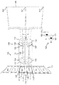
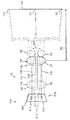
図1は、デュアルレンズ3Dフィルム投影システムとも呼ばれる、上/下レンズ3Dフィルム投影システム100を示す。矩形の左眼画像112および矩形の右眼画像111は、両方とも上/下3Dフィルム110上にあるが、フィルムの後ろに置かれた光源および集光器(図示していないが、合わせて「照明器」と呼ばれる)によって同時に照射されると同時に、フィルム110上の他のすべての画像が、アパーチャプレートの不透明部分で覆われているために可視的にならないように、アパーチャプレート120(分かりやすくするために、アパーチャの内縁のみを図示している)によってフレーミングされる。アパーチャプレート120を通して可視的な左眼画像および右眼画像(立体画像ペアを形成する)は、上/下レンズシステム130によってスクリーン140に投影され、概して、両方の投影画像の最上部が、スクリーン可視エリアの上端142に位置合せされ、投影画像の最下部が、スクリーン可視エリアの下端143に位置合せされるように、位置合せされ、重ねられる。
FIG. 1 shows an upper / lower lens 3D
上/下レンズシステム130は、本体131、入口端132、および出口端133を含む。レンズシステム130の上半分および下半分は、2つのレンズアセンブリとも呼ばれ、迷光が2つのレンズアセンブリの間を横切るのを防止する中隔138によって隔てられる。上側レンズアセンブリは、通常は右眼画像に関連づけられ(すなわち、画像111などの右眼画像を投影するのに使われ)、入口レンズ134および出口レンズ135を有する。下側レンズアセンブリは、通常は左眼画像に関連づけられ(すなわち、画像112などの左眼画像を投影するのに使われ)、入口レンズ136および出口レンズ137を有する。デュアルレンズシステム130の各半分の内部の他のレンズ要素およびアパーチャ絞りについては、分かりやすくするために図示していない。追加レンズ要素、たとえば、デュアルレンズ130の出口端に続く拡大鏡が、投影システム100の正しい調整にとって適切な場合は追加されてもよいが、図1には示していない。投影スクリーン140は、2つのフィルム画像111、112の投影画像の中心となる可視エリア中心点141を有する。
Upper /
左眼画像および右眼画像112、111は、それぞれ、左眼および右眼符号化フィルタ152、151(投影フィルタとも呼ばれ得る)を通して投影される。立体画像を見るために、観衆メンバ160は、観衆の右眼161が右眼復号フィルタ171を覗き、左眼162が左眼復号フィルタ172を覗くように、適切な復号もしくはビューイングフィルタまたはシャッターを有する眼鏡をかける。左眼符号化フィルタ152および左眼復号フィルタ172は、左眼162が、投影右眼画像ではなく、スクリーン140上で投影左眼画像のみを見るように選択され、配向される。同様に、右眼符号化フィルタ151および右眼復号フィルタ171は、右眼161が、左眼画像ではなく、スクリーン140上で投影右眼画像のみを見るように選択され、配向される。
The left eye image and
この目的に適したフィルタの例は、直線偏光子、円偏光子、アナグリフ(たとえば、赤と青)、ならびにインターレース干渉櫛形フィルタを、それ以外のものの中でも特に含む。たとえば、液晶ディスプレイ(LCD)シャッターを使って、対応するフィルム画像の投影をなくすように動作する同様のタイミングのシャッターと同期して左眼または右眼を交互に遮るアクティブシャッター眼鏡も、可能である。 Examples of filters suitable for this purpose include linear polarizers, circular polarizers, anaglyphs (eg, red and blue), and interlaced interferometric comb filters, among others. For example, active shutter glasses are also possible that use a liquid crystal display (LCD) shutter to alternately block the left or right eye in synchronism with a similarly timed shutter that operates to eliminate projection of the corresponding film image. .
残念ながら、フィルタ151、152、171、172の物理的または性能関連制約により、また、一部のケースでは、スクリーン140および投影システム100の形状により、ゼロではない量のクロストークが存在する場合があり、この場合、投影左眼画像はわずかに、すなわち、かすかにまたは比較的低い彩度で、右眼161に対して可視的になり、投影右眼画像は、左眼162に対してわずかに可視的になる。
Unfortunately, there may be a non-zero amount of crosstalk due to the physical or performance related constraints of the
このクロストークは、漏洩としても知られ、投影画像中のオブジェクトの一部に関して、わずかな二重像を結果的に生じる。この二重像は、良くても気が散るものであり、最悪の場合は、3Dの知覚を妨げ得る。したがって、クロストークをなくすことが望ましい。 This crosstalk, also known as leakage, results in a slight double image of some of the objects in the projected image. This double image is distracting at best, and in the worst case can impede 3D perception. Therefore, it is desirable to eliminate crosstalk.
一実施形態では、フィルタ151、152は、直線偏光子であり、たとえば、出口レンズ135の後に垂直配向で置かれた吸収直線偏光子151、および出口レンズ137の後に水平配向で置かれた吸収直線偏光子152である。スクリーン140は、偏光保持投影スクリーン、たとえば、映写幕である。観衆のビューイング眼鏡は、垂直偏光軸をもつ直線偏光子である右眼ビューイングフィルタ171、および水平偏光軸をもつ直線偏光子である左眼ビューイングフィルタ172を含む(すなわち、眼鏡の各ビューイングフィルタまたは偏光子は、それぞれの立体画像に関連づけられた、それに対応するフィルタまたは偏光子151または152と同じ偏光配向である)。したがって、デュアルレンズ130の上半分を通して投影される右眼画像111は、フィルタ151を通過した後、垂直偏光され、垂直偏光は、投影画像がスクリーン140によって反射されるときに保存される。垂直偏光されたビューイングフィルタ171は、右眼画像用の投影フィルタ151と同じ偏光を有するので、投影右眼画像111は、観衆の右眼161で見ることができる。ただし、投影右眼画像111は、水平偏光された左眼フィルタ172によってほぼ遮られることになるので、観衆の左眼162が投影右眼画像111を見ることはない。残念ながら、このようなフィルタの性能特性は、常に理想的なわけではなく、こうした非理想特性の結果として、クロストークが生じ得る。
In one embodiment, the
この例では、観衆メンバ160の左眼162への投影右眼画像のクロストーク率(漏洩)は、3つの一次因子の関数である。すなわち、第1は、右眼符号化フィルタ151が水平偏光を透過させる量であり(ここで、フィルタ151は、主に垂直偏光を透過するように配向される)、第2は、スクリーン140が、反射する光の偏光を保存することができない度合であり、第3は、右眼画像の投影に使われる垂直偏光を、左眼復号フィルタ172が透過する量である(ここで、フィルタ172は、主に水平偏光を透過するように配向される)。
In this example, the crosstalk rate (leakage) of the right eye image projected to the
こうした因子は、画像全体に等しく影響する、測定可能な物理的値または量である。ただし、スクリーンにおいて測定され得る変形もあり(たとえば、偏光が維持される度合は、入射角もしくは視野角、または両方によって変わり得る)、異なる波長で測定され得る変形もある(たとえば、偏光子が、スペクトルの青色部分の望ましくない偏光を、赤色部分よりも透過し得る)。クロストークは、投影システムの1つまたは複数の構成要素から起こるので、投影システムに、または立体画像の投影に関連づけられているということができる。 These factors are measurable physical values or quantities that affect the entire image equally. However, there are deformations that can be measured at the screen (eg, the degree to which polarization is maintained can vary depending on the angle of incidence or viewing angle, or both), and there are also deformations that can be measured at different wavelengths (eg, a polarizer Undesired polarization of the blue part of the spectrum may be transmitted more than the red part). Since crosstalk occurs from one or more components of the projection system, it can be said to be associated with the projection system or with the projection of a stereoscopic image.
今日の一部の立体デジタル投影システム(図示せず)では、投影左眼画像のピクセルは、投影右眼画像のピクセルと厳密に位置合せされる。というのは、両方の投影画像が、ちらつきの知覚を最小限にするように、十分に速い速度で、左眼画像と右眼画像との間で時分割多重化される同じデジタル撮像装置上で形成されているからである。第1の画像の、第2の画像へのクロストークは、第2の画像中のピクセルの輝度を、第1の画像中の同じピクセルからの予想クロストーク分だけ削減することによって補償され得ることが知られている(前引用中のCowanを参照されたい)。予想された値のクロストークが起こると、違う方の眼の投影画像(たとえば、第1の画像)から漏れる光の量は、正しい方の眼の投影画像(たとえば、第2の画像)の輝度が削減された量をほぼ回復する。この補正は、色彩的に(たとえば、プロジェクタの青が、緑もしくは赤とは異なる量のクロストークを主に呈するケースを補正する)、または空間的に(たとえば、スクリーンの中心が、縁部より少ないクロストークを呈するケースを補正する)変わり得ることがさらに知られている。ただし、こうした公知のクロストーク補正方法では、左眼画像および右眼画像の投影ピクセルの間の完全な整合(registration)を仮定しているが、これは、本発明において扱うような、差分歪みが存在する他の投影システムには適さない。実際、一定の環境において、差分歪みから起こる画像の位置合せ不良を考慮せずに、公知のクロストーク補正方法を、投影立体画像に適用することにより、クロストークの悪影響を、より可視的にすることによって悪化させる場合がある。 In some today's stereo digital projection systems (not shown), the pixels of the projected left eye image are strictly aligned with the pixels of the projected right eye image. This is because both projected images are on the same digital imager that is time-division multiplexed between the left and right eye images at a sufficiently fast rate to minimize flicker perception. It is because it is formed. Crosstalk of the first image to the second image can be compensated by reducing the brightness of the pixels in the second image by the expected crosstalk from the same pixels in the first image. Is known (see Cowan, cited above). When the expected value of crosstalk occurs, the amount of light leaking from the different eye projection image (eg, the first image) is the brightness of the correct eye projection image (eg, the second image). Almost recovers the reduced amount. This correction can be chromatic (eg, correcting the case where the projector's blue primarily exhibits a different amount of crosstalk than green or red) or spatially (eg, the center of the screen is more than the edge). It is further known that it can change) (correcting the case of low crosstalk). However, such a known crosstalk correction method assumes perfect registration between the projection pixels of the left eye image and the right eye image, but this does not cause differential distortion as handled in the present invention. Not suitable for other existing projection systems. In fact, in a certain environment, a known crosstalk correction method is applied to a projected stereoscopic image without considering image misalignment caused by differential distortion, thereby making the adverse effects of crosstalk more visible. It may be worsened.
ここで図2を参照すると、投影プレゼンテーション200が、中心点141、垂直中心線201、水平中心線202を有する投影スクリーン140の視覚部分に示される。正しく位置合せされると、左眼投影画像および右眼投影画像は、垂直中心線201に水平中心が置かれ、水平中心線202に垂直中心が置かれる。投影左眼画像および右眼画像の最上部は、可視スクリーンエリアの最上部142に近く、投影画像の最下部は、可視スクリーンエリアの最下部143に近い。この状態において、結果として得られる投影左眼および右眼画像112、111の境界は、それぞれ、実質的に左眼投影画像境界212および右眼投影画像境界211となる(以下の説明を分かりやすくするために、図2には、差分歪みを誇張して示してある)。
With reference now to FIG. 2, a
レンズ130の性質により、画像111、112は、スクリーン140に投影されると、反転される。したがって、左眼画像112の最下部112B(アパーチャプレート120における開口の中心に近い)は、投影スクリーン140の可視部分の下端143に向かって投影される。同様に、右眼画像111の最上部111T(アパーチャプレート120における開口の中心に近い)は、スクリーン140の可視部分の上端142に向かって投影される。一方、左眼画像112の最上部112Tは、上端142の近くに投影され、右眼画像111の最下部111Bは、投影スクリーン140の可視部分の下端143の近くに投影される。
Due to the nature of the
図2には、2つの投影右眼画像と左眼画像との間の差分歪み、すなわち、異なる幾何歪みの存在も示す。差分歪みは、右眼画像および左眼画像に関する相異なる投影形状から起こる。この例では、投影右眼画像は、境界211および隅AR、BR、CR、DRをもつ、わずかに歪んだ四辺形で表され、左眼画像は、境界212および隅AL、BL、CL、DLをもつ、わずかに歪んだ四辺形で表される。
FIG. 2 also shows the differential distortion between the two projected right eye images and the left eye image, ie, the presence of different geometric distortions. Differential distortion results from different projection shapes for the right eye image and the left eye image. In this example, the projected right eye image is represented by a slightly distorted quadrilateral with
右眼画像境界211および左眼画像境界212は、投影立体画像の差分キーストーン歪みが、垂直中心線201に対して水平方向に対称であり、左眼の差分キーストーン歪みが、右眼のものと、水平中心線202に対して垂直方向に対称であるシステム位置合せを例示している。キーストーニング歪みは、主に、右眼画像111がデュアルレンズ130の上半分によって投影され、デュアルレンズ130の下半分よりも、可視エリア(または投影画像エリア)の下端143からさらに離れて置かれるために生じる。レンズ130の下半分と比較して、レンズ130の上半分に対して、スクリーンまでの距離がわずかに増大したことにより、左眼画像に比較して、投影右眼画像に対する倍率がわずかに増大するが、これは、投影左眼画像212の下端DLCLに比較してより長い、投影右眼画像211の下端DRCRによって明らかである。一方、デュアルレンズ130の上半分は、レンズ130の下半分よりも、可視エリアの上端142に近い。したがって、投影右眼画像211の上端ARBRは、投影左眼画像212の上端ALBLより短い。
In the right
スクリーン140の左上隅の近くの所で、左眼投影画像境界212には、水平拡大キーストーン誤差233(ALにはキーストーン歪みがない場合の、隅ALと隅Aとの間の水平距離を表す)ならびに垂直拡大キーストーン誤差231がある。対称的に位置合せされると、同様の誤差が、スクリーン140の右上隅でも見られる。スクリーン140の左下隅の近くで、左眼投影画像境界212には、水平縮小キーストーン誤差234、および垂直縮小キーストーン誤差232がある。
At near the upper left corner of the
単なる差分キーストーニングに加え、追加差分歪み、たとえば差分糸巻き形歪みが存在する場合があり、この場合、スクリーン140の最上部142に対する、投影右眼画像212の中央上部での垂直拡大誤差221は、隅での垂直拡大キーストーン誤差231と同じとは限らない。同様に、投影右眼画像212の中央最下部での垂直縮小誤差222は、垂直縮小誤差232と同じとは限らない。(この例では、簡潔にするために、追加水平歪みは図示していない。)
後で論じるように、右眼画像と左眼画像との間の差分歪みは、第1の眼の画像のピクセルから第2の眼の画像へのクロストーク寄与を判定するのに考慮される必要がある。
There may be additional differential distortion, for example, differential pincushion distortion, in addition to mere differential keystoneing, where the
As discussed later, the differential distortion between the right eye image and the left eye image needs to be considered in determining the crosstalk contribution from the first eye image pixel to the second eye image. There is.
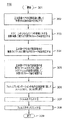
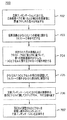
図3Aは、左眼投影画像と右眼投影画像との間の予想クロストークが補正された、複数の立体画像を有する立体フィルムまたはプレゼンテーションを生成するプロセス300を示す。予想クロストークは、所与の投影システムにおいて投影されると、立体像ペアの左眼画像と右眼画像との間で観察されることになるクロストーク値を指す。ステップ301で、結果として得られたフィルムが、たとえば、システム100やデュアルプロジェクタシステムなどのデュアルレンズ投影システムを使って投影される劇場が、選択される。同様の投影システムをもついくつかの劇場に対してフィルムが用意されている場合、こうした劇場は、後で説明するように、歪みおよび/またはクロストーク判定の目的のために選ばれた、識別済みまたは代表的なものでよい。
FIG. 3A shows a
ステップ302
ステップ302で、選択された劇場またはシステムにおいて投影されるべき立体像ペアの左眼画像と右眼画像との間の予想差分歪みが、測定、モデリング、または推定いずれかによって判定される。差分歪みは、投影システムからの1つまたは複数の歪みから起こる、立体画像ペアの、投影された第1の画像と第2の画像との間で観察される歪み、たとえば、キーストーニング、糸巻き形の差を、それ以外のものの中でも特に指し、投影される左画像および右画像に現れるときのピクセルの場所の差によって表すことができる。差分歪みは、立体画像の投影に関連づけられていると言うこともできる。ステップ302で、左眼画像および右眼画像の差分歪みを互いに対して測定する代わりに、両方の画像の歪みは、共通参照、たとえば、スクリーンに対して測定することもできる。歪み測定用の画像は、フィルムループとして与えることができ、画像は、立体フィルムまたは動画プレゼンテーションにおける実際の画像でなくてよい。
At
一例では、左眼投影画像および右眼投影画像212、211それぞれにおける座標に対する基準マーキングを有するテストパターン(図示せず)を使って、一方の眼の画像の座標と、他方の眼の画像の座標との間の相互参照を、たとえば、投影を検査することによって与えることができ、スクリーン上の共通点は、左眼および右眼の画像両方に対する座標中に配置することができる。このようにして、左眼画像中のピクセルと、左眼画像ピクセルにおけるクロストークに寄与する(すなわち、クロストーク寄与を生じる)ことが予想される、右眼画像中の1つまたは複数のピクセルとの間の対応が確立される。この対応については、図4、5とともにさらに詳しく論じる。
In one example, using a test pattern (not shown) with reference markings for coordinates in the left eye projection image and right
ステップ302の別の実施形態では、投影左眼画像および右眼画像211、212の対応する隅が一致しない量を推定することによって、歪みを得ることができる。たとえば、投影画像212の左上隅ALは、投影画像211の左上隅ARよりさらに左上に、たとえば水平方向に2インチ(5.08cm)、および垂直方向に1インチ(2.54cm)の所にあり、これは、40フィート(12.19m)のスクリーンの場合は、水平方向に約8ピクセル、および垂直方向に4ピクセルとなり得る(投影画像が約2000ピクセルの幅であり、アナモルフィック投影が使われないと仮定する)。差分歪みがほぼ対称、たとえば、垂直中心線201に対して対称であるケースでは、この単一の隅は、一方の画像における座標を、他方の画像における座標に変形させ、または相関させるように、投影画像211、212の2つの台形境界の形状を記述するのに十分であり得る。たとえば、差分歪みが、所与の眼の画像に関して、垂直中心線201に対して対称な場合、所与の高さにあるとともに中心線201の左にずらされているピクセルは、中心線201の右に同じ量だけずらされている(同じ高さにある)ピクセルと同じ規模の歪みを有することになる。この場合(図1〜2に示す、単純な軸上のケース)、どの糸巻き形または樽型歪みも無視すると、投影左眼画像および左眼画像の差分歪みは、水平中心線202に対して互いの鏡像にもなり、すなわち、左眼画像は、水平中心線202に対して垂直方向に裏返された場合、投影右眼画像と重なる。
In another embodiment of
たとえば、投影右眼画像211の左上隅ARが、右眼画像座標{0,0}をもち、右下隅CRが{2000,1000}である場合、隅ARとALとの間の観察される不一致(すなわち、8ピクセルの水平隔離および4ピクセルの垂直隔離)は、投影右眼画像211の左上隅ARが、左眼画像212の座標空間における{8,4}という座標に対応し、右眼画像211の右下隅CRが、左眼画像212の座標空間における{2008,1004}という座標に対応することを、こうした座標が投影画像212の限界の外にある場合であっても、示すことになる。
For example, the upper left corner A R of the projected right-
同様に、左眼画像212の右下隅CLは、右眼画像中の約{1992,996}の座標に対応して見えるはずであり、投影左眼画像212の左上隅ALは、投影右眼画像211の限界の外にある場合であっても、右眼画像の座標中の約{−8,−4}の座標に対応することになる。投影システム100が対称的に位置合せされる場合、スクリーン140の中心141は、投影左眼画像および右眼画像212、211両方の座標空間中の座標{1000,500}に対応することになる。左眼画像中のいくつかの場所および左眼および右眼座標空間中の対応する座標の例を、テーブル1に挙げる(テーブル中で、「中心(center)」は、最上部と最下部との間の中点を指し、「中央(middle)」は、左と右との間の中点を指す)。
Similarly, the lower right corner C L of the left-

こうした座標値に基づいて、左眼画像中の他の場所の座標は、たとえば、歪みの性質に最も適合する公式を使う補間によって得ることができる。たとえば、上で論じた単純な遠近(台形)歪みに対して、以下の式を使って、左眼画像座標{xL,yL}を右眼画像座標{xR,yR}に換算することができる。
式1:
xR=xL−8[(yL−yC)/yC]*[(xL−xC)/xC]
yR=yL−4(yL−yC)2/yC 2
上式で、{xC,yC}は、中心点{1000,500}である。
{xR,yR}から{xL,yL}への、ピクセルの小片にまで及ぶ逆変態は、式2によって与えられる。
xL=xR+8[(yR−yC)/yC]*[(xR−xC)/xC]
yL=yR+4(yR−yC)2/yC 2
Based on these coordinate values, the coordinates of other locations in the left eye image can be obtained, for example, by interpolation using a formula that best fits the nature of the distortion. For example, for the simple perspective (trapezoidal) distortion discussed above, the left eye image coordinates {x L , y L } are converted to right eye image coordinates {x R , y R } using the following equations: be able to.
Formula 1:
x R = x L -8 [( y L -y C) / y C] * [(x L -x C) / x C]
y R = y L -4 (y L -y C) 2 /
In the above equation, {x C , y C } is the center point {1000, 500}.
The inverse transformation from {x R , y R } to {x L , y L } down to a small piece of pixels is given by
x L = x R +8 [(y R −y C ) / y C ] * [(x R −x C ) / x C ]
y L = y R +4 (y R -y C) 2 /
ステップ303
ステップ303で、選択された劇場内のシステムによって投影される立体像ペアの左眼画像および右眼画像に関して予想されるクロストーク率は、スクリーン(投影画像空間に対応する)の1つまたは複数の領域で、直接測定し、または推定することができる。クロストークが、投影スクリーン中で大きくは変わらないことが予想され、または分かっている場合、1つの領域でのクロストーク判定で十分である。そうでない場合、このような判定は、追加領域に対しても行われる。大幅な変化と見なされるものは、ビジネス決定またはポリシーに基づく具体的な性能要件に依存する。
In
一実施形態では、クロストーク率は、他方の立体画像に対して、眼鏡のビューイングフィルタから漏れる立体画像の量(すなわち、画像を投影する光)を判定することによって測定される。この測定は、たとえば、投影システム100を通してブランク(透明)フィルムを回し、一方の出力レンズを遮り、たとえば左眼出力レンズ137を不透明物質で覆い、第1の場所での光の量、または観衆メンバ160の位置から右眼フィルタ171を通して見える、スクリーン140の領域、たとえば、中心141を測定することによって行うことができる。この第1の測定は、明画像測定と呼ばれ得る。透明フィルムではなく、オープンフレーム(すなわち、フィルムなし)を使うことができるが、いくつかのフィルタ構成要素、たとえば、偏光子が、高輝度または放射束に対して傷つきやすい場合があるので、好まれない。左眼出力がやはり遮られる同様の測定が、左眼フィルタ172を通して実施され、暗画像測定と呼ばれ得る。
In one embodiment, the crosstalk rate is measured by determining the amount of stereoscopic image that leaks from the eyeglass viewing filter (ie, the light that projects the image) relative to the other stereoscopic image. This measurement can be achieved, for example, by turning a blank (transparent) film through the
こうした2つの測定は、それぞれ、ビューイングフィルタ171、172それぞれを通して点141に向けられたスポット光度計を使って行うことができる。約1または2度の典型的な測定フィールドが達成され得る。こうした測定のために、それぞれのフィルタ171、172は、ビューイング眼鏡フィルタと観衆の左眼および右眼162、161との間と同様の空間的関係で、光度計の光軸に沿って位置合せされ、光度計に対して位置決めされるべきである。暗画像測定値対明画像測定値の比が、漏洩、またはクロストーク率である。任意選択で、他の観衆場所で追加測定を行うことができ、ある特定のスクリーン領域の結果(得られた比)は、平均すればよい(必要とされる場合、加重平均)。
These two measurements can be made using spot photometers directed at
所望される場合、同様の測定を、スクリーン上の他の場所または領域に対して、こうした点に光度計を向けることによって行うことができる。後で論じるように、異なるスクリーン場所に対するこうした測定は、スクリーンの異なる領域中のピクセルに関連づけられたクロストーク値を判定するのに用いることができる。さらに、光度計が、スペクトルに対して敏感である、すなわち、波長に応じた明るさを測定することが可能である場合、変色に関してクロストークを評価すればよく(たとえば、クロストークが、スペクトルの青色部分において、緑または赤より高いかどうか)、そうすることによって、プリント用フィルムの各色染料に関して個別のクロストーク率を判定することができる。 If desired, similar measurements can be made by pointing the photometer to these points relative to other locations or areas on the screen. As discussed later, such measurements for different screen locations can be used to determine crosstalk values associated with pixels in different areas of the screen. In addition, if the photometer is sensitive to the spectrum, i.e. it is possible to measure the brightness as a function of wavelength, it is only necessary to evaluate the crosstalk for discoloration (e.g. In the blue part, whether higher than green or red), by doing so, an individual crosstalk rate can be determined for each color dye of the printing film.
別の実施形態では、クロストーク率は、たとえば、左眼画像および右眼画像に対してそれぞれのテスト用コンテンツまたはパターンを与えることによって直接観察することができる。一例として、濃度勾配(図示せず)の値が0%透明度から20%透明度(すなわち、最大濃度から、予想される最悪のクロストークケースを少なくとも表す、光を入れる比較的低い濃度までだが、これは他の例における20%とは異なり得る)の範囲であるパターンを、左眼画像112において与えればよく、右眼画像111におけるパターン(図示せず)は、100%の透明度、すなわち、最小濃度で与えられる。右眼画像から左眼画像へのクロストーク率を判定するために、観察者は、左眼フィルタ172を通して左眼162のみでテストコンテンツを見ることによって、どの勾配値が、左眼フィルタ172を通して漏れる右眼パターンの外見的彩度に最も合致するか、視覚的に判定すればよい。
In another embodiment, the crosstalk rate can be observed directly, for example, by providing respective test content or patterns for the left eye image and the right eye image. As an example, the value of a density gradient (not shown) ranges from 0% transparency to 20% transparency (ie, from the maximum density to a relatively low concentration of light that represents at least the worst possible crosstalk case expected) Can be different from 20% in other examples) in the
左眼パターンは、スクリーンの上半分に投影される立体またはチェッカーボードパターンでよく、左側での0%の透明度(すなわち、黒)から、右側での20%の透明度までを与える濃度勾配を有する(たとえば、チェッカーボード中の黒色正方形は常に黒であるが、「明るい」または黒色でない正方形は、0%から20%の範囲の透明度である)。右眼パターンも、スクリーンの下半分に投影される立体またはチェッカーボードパターンでよい(たとえば、チェッカーボードの明るい正方形は、最小濃度、すなわち、完全な、100%の明るさである)。左眼フィルタのみを通して眺める観察者は、左から右の間のどこで、スクリーンの上半分(左眼画像)におけるパターンが、スクリーンの下半分(右眼画像)でのパターンと彩度を合致させるか、つまり、どこで最下部パターンの漏洩が、スクリーンの最上部での勾配と最も合致するか、気づくことができる。 The left eye pattern can be a solid or checkerboard pattern projected onto the upper half of the screen, with a density gradient that gives 0% transparency on the left side (ie, black) to 20% transparency on the right side ( For example, black squares in a checkerboard are always black, but “bright” or non-black squares have a transparency in the range of 0% to 20%). The right eye pattern can also be a solid or checkerboard pattern projected onto the lower half of the screen (eg, a bright square on the checkerboard is the minimum density, ie, full, 100% brightness). For observers looking only through the left eye filter, where between left and right, the pattern in the upper half of the screen (left eye image) matches the saturation in the pattern in the lower half of the screen (right eye image) That is, it can be noticed where the leakage of the bottom pattern most closely matches the gradient at the top of the screen.
個別のカラーテストパターンを使って、プリント用フィルム110のシアン、黄色、およびマゼンタ染料それぞれに対して個別のクロストーク率を得ることができる。
Individual color test patterns can be used to obtain individual crosstalk rates for each of the cyan, yellow, and magenta dyes of the
ステップ303のさらに別の実施形態では、クロストーク率は、素材または構成要素(たとえば、フィルタおよびスクリーン)の仕様から推定することができる。たとえば、右眼フィルタ151が、垂直偏光の95%および水平偏光の2%を通すことが分かっている場合、これは、左眼162への約2.1%(0.02/0.95)の漏洩を表す。スクリーン140が映写幕であり、反射光の94%において偏光を保存するが、残りの5%に対しては偏光を妨げる場合、これは、どちらかの眼への、さらに5.3%の漏洩(0.05/0.94)を表す。左眼水平偏光フィルタ172が、水平偏光の95%を通すが、垂直偏光の2%を通させる場合、これは、さらに2.1%の漏洩である。合わせると、こうした異なる漏洩寄与は、(第1次成分において)約9.5%の漏洩になり、全体的なクロストーク率を結果的に生じ、すなわち、右眼画像からの光の断片が、左眼によって観察される。
CALC1:
In yet another embodiment of
CALC1:
より高度な正確さが要求される場合、より詳細でありより高次の算出を用いればよく、この算出では、光路中の各要素での光漏洩または偏光変化、たとえば、偏光フィルタ要素を通る誤った偏光の通過や、スクリーンによる偏光変化を考慮する。一例では、右眼画像から左眼画像へのクロストーク率の完全な高次算出は、
CALC2:
If a higher degree of accuracy is required, a more detailed and higher order calculation may be used, which involves light leakage or polarization changes at each element in the optical path, e.g., error through polarization filter elements. Consider the passage of polarized light and the change in polarization by the screen. In one example, a complete high-order calculation of the crosstalk rate from the right eye image to the left eye image is
CALC2:
によって表すことができる。上記式において、分子中の括弧で囲まれた各項は、光路中の要素、たとえば、投影フィルタ、スクリーンおよびビューイングフィルタから起こる、正しくない画像への漏洩項または漏洩寄与(すなわち、第2の画像のビューイングフィルタを通過し、違う方の眼で見える、立体像ペアの第1の画像からの光)を表す。分母中の括弧で囲まれた各項は、正しい画像に光を実際に与える漏洩を表す。 Can be represented by In the above equation, each parenthesized term in the numerator is a leakage term or contribution to the incorrect image (ie, the second contribution) arising from elements in the optical path, such as projection filters, screens and viewing filters. (Light from the first image of a stereoscopic image pair) that passes through the image viewing filter and is visible to the other eye. Each term in parentheses in the denominator represents a leak that actually gives light to the correct image.
この状況において、各漏洩は、立体画像に関連づけられた光が、要素(たとえば、少量の水平偏光を通す垂直偏光子となるように設計されたフィルタや、少量の偏光変化をもたらす偏光保存スクリーン)の非理想性能特性により、「正しくない」(または意図しない)偏光配向で透過され、または反射される各時間を指す。 In this situation, each leak is caused by the light associated with the stereoscopic image being an element (eg, a filter designed to be a vertical polarizer that passes a small amount of horizontal polarization, or a polarization preserving screen that results in a small amount of polarization change). Refers to each time that is transmitted or reflected in a “wrong” (or unintentional) polarization orientation.
上記CALC2の式において、奇数の漏れ(1または3)を表す項は、漏洩寄与として分子に現れ、偶数の「漏れ」(ゼロまたは2)を含む項は、正しい画像に寄与するものとして、分母に現れる。正しい画像への後者の寄与は、たとえば、間違って偏光された光(たとえば、不完全な偏光フィルタによって通される)の断片が、スクリーン(偏光を保存しているはずである)から反射されると、偏光を変化させるときに起こる場合があり、結果的に、正しい方の目で漏洩が見える。 In the CALC2 equation above, terms that represent an odd number of leaks (1 or 3) appear in the numerator as leak contributions, and terms that contain an even number of “leaks” (zero or 2) contribute to the correct image Appear in The latter contribution to the correct image is, for example, that a piece of wrongly polarized light (eg passed by an imperfect polarizing filter) is reflected from the screen (which should preserve polarization) May occur when the polarization is changed, and as a result, the leakage is visible with the correct eye.
たとえば、CALC2の分子の第3項は、右眼画像投影フィルタ151によって引き起こされる漏洩の断片(2%)が、スクリーン140によって変化せず(94%)、左眼ビューイングフィルタ172によって通される(95%)ままであることを表す。分母の第4項は、水平に偏光された光がフィルタ151によって漏れたときの、正しい画像への光漏洩寄与が、その偏光を、スクリーン140によって垂直偏光に変化させて戻しており、その結果、垂直偏光フィルタ171によって通されるときに正しい画像に寄与する漏洩を生じることを表す。
For example, the third term of the molecule of CALC2 is passed by the left
ただし、CALC2のより詳細な算出は一般に、第1次算出(CALC1)からのより簡易な推定値とわずかに異なるだけの値を生じるので、ほとんどの場合、より簡易な算出が妥当である。 However, a more detailed calculation of CALC2 generally results in a value that is only slightly different from the simpler estimate from the primary calculation (CALC1), so in most cases a simpler calculation is reasonable.
上記から、クロストーク率を測定し、算出し、または推定する他の技法が、当業者には明らかであろう。 From the above, other techniques for measuring, calculating, or estimating the crosstalk rate will be apparent to those skilled in the art.
ステップ304
ステップ304で、フィルムまたは動画プレゼンテーションの1つのフレーム用の立体像ペアの投影画像、たとえば、図1の画像111、112中の複数のピクセルに関するクロストーク値が判定される(「ピクセル単位」のクロストーク値判定と呼ばれ得る)。後で説明するように、第1の眼の画像中の所与のピクセルに関するクロストーク値は、第2の眼の画像の近接ピクセルから予想されるクロストーク寄与から判定され、近接ピクセルは、ステップ302からの歪み情報に基づいて識別される。フィルムに対するクロストーク補正の状況において、「ピクセル」という用語の使用は、デジタル中間物、すなわち、フィルムのデジタル化バージョンのピクセルを指し、これは、当業者の認識の通り、通常は、ポストプロダクションにおけるフィルム編集が今日どのように行われるかということである。あるいは、ピクセルは、たとえば、スクリーン上の場所に対応する投影画像空間に対して使うこともできる。
At
一実施形態では、クロストーク値判定および/または補正が、左眼画像および右眼画像中の全ピクセルに関して所望され、または必要とされることが仮定される。したがって、左眼画像および右眼画像両方における全ピクセルに関して、クロストーク値が判定されることになる。ただし、他の実施形態では、たとえば、画像どちらかの一定のピクセルまたは部分に関してクロストーク補償が必要とされないことが分かっており、または決定された場合、クロストーク値の判定は、立体画像それぞれにおける一部のピクセルに関して実施するだけでよい。 In one embodiment, it is assumed that crosstalk value determination and / or correction is desired or required for all pixels in the left and right eye images. Therefore, the crosstalk value is determined for all pixels in both the left eye image and the right eye image. However, in other embodiments, it is known that, for example, no crosstalk compensation is required for certain pixels or portions of either of the images, or if determined, the determination of the crosstalk value is determined in each stereoscopic image. It only needs to be done for some pixels.
検討中の第1の眼の画像中の所与のピクセルに対して、所与のピクセルの投影に近接して投影される、第2の眼の画像の1つまたは複数のピクセルが識別され、(他方の眼の画像の)近接ピクセルそれぞれからの、所与のピクセルの総クロストーク値への寄与が判定される。たとえば、ステップ302(立体画像ペアの間の差分歪みを判定する)からの結果に基づいて、左眼画像および右眼画像にあるピクセルは、共通座標系に、たとえば、一方の画像の座標系から、他方の画像の座標系に、たとえば、式1または式2を使って変換することができ、そうすることによって、2つの画像にあるピクセルの間の対応を確立することができ、第1の眼の画像の所与のピクセルに関連づけられた(第2の眼の画像にある)クロストーク寄与または近接ピクセルを識別することができる。
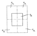
For a given pixel in the first eye image under consideration, one or more pixels of the second eye image that are projected proximate to the projection of the given pixel are identified; The contribution of each given pixel (in the other eye image) to the total crosstalk value for a given pixel is determined. For example, based on the result from step 302 (determining the differential distortion between a pair of stereoscopic images), the pixels in the left eye image and the right eye image are in a common coordinate system, eg, from the coordinate system of one image. , Can be transformed into the coordinate system of the other image, for
このことは、図3Bに示してあり、図3Bは、第1の画像中の検討中のピクセルと、他方の眼の画像にあるいくつかのピクセル(他方の眼の画像から、検討中のピクセルへのクロストーク寄与が判定されることになるピクセル)との間の空間的関係を示す。この例では、右眼画像の投影ピクセルPRは、左眼画像の投影ピクセルP1L、P2L、P3L、P4L(破線矩形)に近接しており、左眼画像にあるこうした近接ピクセルは、ピクセルPRでのクロストーク値に寄与すると予想される。左眼画像にあるこうした近接ピクセルはそれぞれ、ピクセルPRでのクロストーク値への、その相対寄与をさらに特徴とする。差分歪みがないので、右眼画像および左眼画像中のピクセルは、1対1対応を有し、互いに重なることに留意されたい。差分歪みがある場合は、概して、ゼロでないクロストークに寄与する一方の画像から、他方の画像中の所与のピクセルまで、複数の近接ピクセル(たとえば、少なくとも2つ)が存在することになる。 This is illustrated in FIG. 3B, which shows that the pixel under consideration in the first image and some pixels in the image of the other eye (from the image of the other eye, the pixel under consideration And the spatial relationship between the pixel (s) to which the crosstalk contribution is to be determined. In this example, projection pixels P R of the right-eye image projection pixels P 1L of the left eye image, P 2L, P 3L, is close to the P 4L (dashed line rectangle), Such neighbors in the left-eye image , it is expected to contribute to the crosstalk value at the pixel P R. Each eye such neighbors is in the image, to the crosstalk value at the pixel P R, and further characterized their relative contributions. Note that the pixels in the right and left eye images have a one-to-one correspondence and overlap each other because there is no differential distortion. In the presence of differential distortion, there will generally be multiple neighboring pixels (eg, at least two) from one image contributing to non-zero crosstalk to a given pixel in the other image.
この例では、第2の眼の画像には、第1の眼の画像のピクセルに近接していると見なされる4つのピクセルがあり、こうしたピクセルは、第1の眼の画像のクロストークに均等な割合を与えるので、それぞれの寄与は25%になる。ステップ303で、この画像領域に関して判定されたクロストーク率は、XT(百分率または分数で表されるクロストーク率)なので、検討中のピクセル(たとえば、右眼画像中のピクセルPR)に関するクロストーク値
In this example, there are four pixels in the second eye image that are considered to be close to the pixels of the first eye image, and these pixels are equivalent to the crosstalk of the first eye image. Each ratio is 25%. In
![]()
![]()
は、 Is
![]()
![]()
とc(PiL,PR)との積の合計のXT倍であり、ここで、式3に示すように、 And c (P iL, P R) is X T times the sum of the product of the, here, as shown in Equation 3,
![]()
![]()
は、他方の眼の各近接ピクセル、たとえば、左眼画像ピクセルPiLの値であり(ここで、iは、各近接左眼ピクセルの索引であり、たとえば、図3Bではi=1から4である)、c(PiL,PR)は、ピクセルPiLからピクセルPRへのクロストーク寄与である(それぞれ、この例では25%に等しい)。
式3:
Is the value of each neighboring pixel of the other eye, eg, the left eye image pixel P iL (where i is the index of each neighboring left eye pixel, eg, i = 1 to 4 in FIG. 3B) C) (P iL , P R ) is the crosstalk contribution from pixel P iL to pixel P R (each equal to 25% in this example).
Formula 3:
この考察において使われているように、ピクセルの「値」は、たとえば、明るさまたは輝度、およびおそらく色でよい、ピクセルのプロパティの1つまたは複数からなる表現を指す。c(PiL,PR)は、最も近いピクセルPiLで、たとえば、0〜100%の範囲でオーバーレイされるピクセルPRの断片を表す。 As used in this discussion, a “value” of a pixel refers to a representation consisting of one or more of the properties of the pixel, which may be, for example, brightness or luminance, and possibly color. c (P iL, P R) is the nearest pixel P iL, for example, represents the fragment of a pixel P R, which is overlaid with a range of 0 to 100%.
![]()
![]()
とc(PiL,PR)との積は、近接ピクセルPiLからの「クロストーク寄与値」と呼ばれ得る。たとえば、明るさ単位(線形単位)が50である最も近いピクセルPiLが、対象ピクセルPRの20%と重なる場合、20%*50=10の明るさ単位が、最も近いピクセルPiLによって、他方の眼の画像のピクセルPRに寄与されるクロストーク値となる。 And c (P iL , P R ) may be referred to as the “crosstalk contribution value” from neighboring pixels P iL . For example, the brightness unit (linear units) is 50 nearest pixel P iL If the overlap is 20% of the target pixel P R, the brightness units 20% * 50 = 10, the nearest pixel P iL, a crosstalk value contributed to the pixel P R of the other eye image.
すべての近接ピクセルPiLからのこうしたクロストーク寄与値の合計にXT、すなわちこの領域におけるクロストーク率(たとえば、ステップ303で測定され、または推定された)を乗算すると、 Multiplying the sum of these crosstalk contribution values from all neighboring pixels P iL by X T , the crosstalk rate in this region (eg, measured or estimated in step 303),
![]()
![]()
の結果は、たとえば、他方の眼の画像からのクロストークまたは光漏洩から生じた、ピクセルPRに関して観察される総余剰明るさに対応する、ピクセルPRに関する総クロストーク値である。そうしなければピクセルPRで観察されるはずの余剰明るさを削減するために、ピクセルPRに関する補償が必要とされるのは、このクロストーク値に関してである。 Result of, for example, resulting from crosstalk or light leakage from other eye image, corresponding to the total excess brightness observed for the pixel P R, the total crosstalk value for the pixel P R. To reduce excess brightness should be observed so and unless pixel P R, what is needed is compensation for the pixel P R is for this crosstalk value.
クロストーク率XTが、1つの画像領域に関してのみ判定される、たとえば、スクリーン全体で空間変化が予想されない場合、この量は、式3で、その画像の全ピクセルに関するクロストーク値を計算するのに使うことができる。 If the crosstalk rate X T is determined for only one image area, for example, if no spatial change is expected across the screen, this amount can be calculated using Equation 3 to calculate the crosstalk value for all pixels in the image. Can be used for
ただし、ステップ303で判定されたクロストーク率が、スクリーン140において変わる場合(すなわち、異なる領域に関して測定値が異なる)、この変化がステップ304で考慮される。たとえば、検討されるピクセルが、クロストーク率が異なる2つの領域の間に置かれている場合、XTの値は、補間によって得ることができる。ステップ303で判定されたクロストーク率が、シアン、黄色、およびマゼンタのプリント染料それぞれで変わる場合、この変化も、たとえば、それぞれのプリント染料色に関する個別のクロストーク率、すなわちXC、XY、XM(百分率として表される)も、このステップで考慮される。
However, if the crosstalk rate determined at
こうした計算の場合、他方の眼のピクセル値は線形値でなければならないことに留意されたい。したがって、ピクセル値が対数値を表す場合、この値は、上記計算において操作される前に、最初に線形表現に変換されなければならない。上の式3における積のスケーリングされた合計から生じるクロストーク値は次いで、対数尺度に変換し戻してよい。クロストークが個々の色に関して別々に検討される場合、上で言及したピクセル値は、色それぞれ、たとえば、赤、青、緑における明るさ(それぞれ、シアン、黄色、およびマゼンタ染料の値を分析するときに測定されるものである)を指す。 Note that for such calculations, the pixel value of the other eye must be a linear value. Thus, if the pixel value represents a logarithmic value, this value must first be converted to a linear representation before being manipulated in the above calculations. The crosstalk value resulting from the scaled sum of products in Equation 3 above may then be converted back to a logarithmic scale. When crosstalk is considered separately for each color, the pixel values mentioned above analyze the brightness values for each color, eg, red, blue, and green (cyan, yellow, and magenta dyes, respectively) Is sometimes measured).
ステップ305
ステップ305で、ステップ304で検討された各ピクセル(すなわち、クロストーク情報、たとえば、クロストーク値が判定されている投影画像中の複数のピクセルそれぞれ)は、投影左眼画像と右眼画像との間に存在すると予想されるクロストーク値を少なくとも部分的に補償するように濃度が調整されてネガフィルムに記録される。具体的には、デジタル中間物における画像からの各ピクセル出力の濃度が、各ピクセルに関して、ステップ304で取得されたクロストーク情報に基づいて判定され、したがって濃度調整は、クロストークからの明るさ増大が、ネガから生成されるフィルムプリントにおいて効果的に補償される(または少なくとも部分的に削減される)ようにフィルム媒体に適用される。
In
たとえば、ステップ304からの所与のピクセルに関するクロストーク値が、CTであると予想される場合、ネガフィルムに対するピクセル出力の濃度は、このネガから(下のステップ307で)作られるフィルムプリントが、このピクセルでの光出力を、クロストーク値CTからの光増大にほぼ等しい量だけ低減するように、CTの関数である量だけ低減されるべきである(すなわち、ネガフィルムをより明るく、またはより透明にする)。別の実施形態では、ネガフィルムの第1の画像中のピクセルに関する濃度低減は、所定の量だけ、第2の画像中の1つまたは複数のピクセルからのクロストーク寄与値を、少なくとも部分的に補償するのに十分である。
For example, if the crosstalk value for a given pixel from
したがって、フィルムプリントは、対応して濃度が増大するが、この濃度は、所与のピクセルに関して投影される光の量を低減させて、ステップ304で計算された対応するクロストーク値を少なくとも部分的に補償し、またはその値とほぼ等しくなる。ピクセルをネガに記録するための濃度または彩度調整の量は、ネガおよびプリント用フィルム向けの、公開されている感度曲線から判定すればよい。
Thus, the film print has a corresponding increase in density, which reduces the amount of light projected for a given pixel and at least partially compensates for the corresponding crosstalk value calculated in
このような曲線は、限られた領域においてのみ、ほぼ線形である。この理由のため、当該分野において公知である、このような補正を実施するためのアルゴリズムは概して、所与のフィルムレコーダ、ネガフィルムストック、およびプリント用フィルムストック向けに経験的に作成されるルックアップテーブル(LUT)を利用する。このようなLUTの考察は、たとえば、非特許文献1に提示されている。いくつかのLUTは、公開されており、たとえば、ニューヨーク州ロチェスターのEastman−Kodakは、Kodak Display ManagerおよびLook Management System製品において自社が製造するフィルムストック用のLUTを公開している。両方の引用対象が、参照によってその全体が本明細書に組み込まれている。
Such a curve is almost linear only in a limited area. For this reason, algorithms known in the art for performing such corrections are generally empirically created lookups for a given film recorder, negative film stock, and printing film stock. A table (LUT) is used. Such consideration of LUT is presented in
ステップ306〜309
ステップ306で、ステップ304、305が、フィルムプレゼンテーションにおける他の立体画像、たとえば、フィルム中の他のフレームに関して繰り返される。いくつかの状態では、フィルムの全フレーム中の全画像に関して濃度調整を実施することが好ましい場合があるが、そうすることが要求されるわけではない。次いで、濃度判定結果に基づいて、ネガフィルム(または他の代替物、たとえば、所望される場合はフィルム画像のデジタルバージョン)を用意すればよい。
At
ステップ307で、ステップ306で用意されたネガフィルムから、フィルムプリントが作られる。
In
ステップ308で、ステップ307からのフィルムプリントが、システム100、または同様のもので投影され、観衆メンバ160によって観賞されると、クロストークの知覚は、クロストーク補正が含まれていないフィルムプリントと比較すると、実質的になくなる。
At
プリントにおいて、片方の眼に関して調整されるべきピクセルが、その最大濃度(すなわち、最も濃い)であっても、他方の眼の画像の投影からのクロストークを完全にオフセットするのに十分なほど、さらに光を削減することができないように、既に高濃度である(すなわち、濃い)という例外的状態が起こり得る。ただし、このような状態は、頻繁に起こるわけではなく、一般に持続期間が短い。 In a print, the pixel to be adjusted for one eye, even at its maximum density (i.e., the darkest), is sufficient to completely offset the crosstalk from the projection of the other eye's image, In addition, an exceptional situation can occur where the concentration is already high (ie dark) so that the light cannot be reduced. However, such a condition does not occur frequently and generally has a short duration.
プロセス300は、ステップ309で終わる。
ステップ304での手順を、第2の立体画像中の近接ピクセルの寄与から起こる、第1の立体画像の所与のピクセルでのクロストーク値を判定する図4、図5の例によりさらに示す。
The procedure at
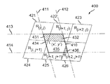
図4は、投影左眼画像ピクセル410(太線の四辺形として示してある)周辺の領域400を示し、ピクセル410は、図4ではL(x',y')として指定される座標{x’,y’}をもつ。左眼ピクセル410に近接して投影されるのは、右眼画像ピクセル421〜426であり、こうしたピクセルはそれぞれ(右眼ピクセル423は除く)、左眼ピクセル410と部分的に重なる。
FIG. 4 shows a
左眼ピクセル410は、左右がそれぞれのグリッド線411、412に、上下がそれぞれグリッド線413、414に接する。この例では、グリッド線411、413は、それぞれ、x’およびy’の座標値をもつと見なすことができ、したがって左眼ピクセル410の左上方隅は、L(x',y')と指定される。4本のグリッド線411〜414は、投影左眼画像212の全体において直線でなくてよいことに留意されたい。ただし、高倍率では、その曲率は一般に無視してよく、この尺度では、真直ぐとして扱われる。この{x’,y’}値は、変換式である上の式1および式2において、xL、yL座標空間での値に対応することに留意されたい。
The
右眼ピクセル421〜426は、この尺度で検討されるときには無視してよい曲率をもつ同様の縁部を有する。こうしたピクセルの左上隅は、ピクセル410のものとは異なる座標系において指定される。たとえば、右眼ピクセル421は、座標{i,j}をもち、R(i,j)と指定され、右眼ピクセル422〜426は、それぞれ、座標{i+1,j}、{i+2,j}、{i,j+1}、{i+1,j+1}、{i+2,j+1}をもつ。こうした{i,j}座標は、上の変換式中では、xR、yR座標空間における値に対応し、式2を使って前述したように、xL、yL座標に変換することができる。
The right eye pixels 421-426 have similar edges with a curvature that can be ignored when considered on this scale. The upper left corner of such a pixel is specified in a different coordinate system than that of
投影されると、右眼ピクセル421、422、424、425、426は、左眼ピクセル410と、対応する交差または重なり領域431、432、434、435、436で重なる(各重なり領域は、それぞれの右眼ピクセルおよび左眼ピクセル410の対応する境界によって画定される)。右眼ピクセル423は、左眼ピクセル410と重ならないので、対応する交差領域はない。
When projected, the
投影される重なり領域431、432、434、435、436それぞれの面積の合計は、投影左眼ピクセル410の面積に等しい。左眼ピクセル410に対する投影右眼ピクセル421の寄与は、重なり領域431の面積を、左眼ピクセル410の投影面積で除算したものとなる。言い換えると、右眼ピクセル421から左眼ピクセル410への寄与は、比A431/A410で与えられ、ここで、A431は、重なり領域431の面積であり、A410は、左眼ピクセル410の面積である。
The total area of each of the projected overlapping
ピクセル421からのこのクロストーク寄与に、ピクセル421の値を乗算し(ここで、ピクセル421の「値」は、観衆メンバ160によって見えるピクセル421の明るさに線形対応する)、続いて、領域400に関してステップ303で判定された予想クロストーク率を乗算すると、結果は、右眼ピクセル421からのクロストークまたは漏洩による、左眼ピクセル410の明らかな明るさ増大となる。小さいキーストーニング角に対して、左眼ピクセル410の面積は、単位元にほぼ等しいものとして扱われることに留意されたい。(この例では、領域400は、検討されるピクセル、たとえば、ピクセル410、および他方の眼の画像にある近接ピクセル、たとえば、ピクセル421〜426を囲むスクリーンの一部分に対応する。)
当業者には公知であるように、各重なり領域431、432、434、435、436の面積は、n個の頂点からなるポリゴンの場合、そのxR,yR座標がxL,yL座標に換算された後で、下の式4に示すように、面積Aを生成する測量公式(Surveyor’s Formula)によって判定することができる(結果として生じる換算座標が整数であることはめったにないことに留意されたい)。
This crosstalk contribution from
As known to those skilled in the art, the area of each
より厳密な結果が必要とされる場合、領域400の投影ピクセルを、スクリーン中心の座標系(図示せず)に換算すればよい。この換算は、投影システム100の配置、システムが置かれる劇場、およびレンズ130の調整に大きく依存する。この場合、右眼ピクセル410の面積は、単位元にほぼ等しいと見なされるべきではなく、やはり上の測量公式で算出されるべきである。
If more precise results are required, the projected pixels in
ステップ302からの、予想差分キーストーニングおよび他の歪みの判定に不確実性がある場合、不確実性は、左眼ピクセル410のサイズをスケールアップすることによって、印加され、または考慮され得る。たとえば、プラスまたはマイナス2分の1ピクセルの不確実性がある場合、この算出の目的のために、ピクセル410に含まれる面積は、グリッド線413に対して直角方向に2分の1ピクセルだけ上向きに、グリッド線412に対して直角方向に2分の1ピクセルだけ右向きに、グリッド線414に対して直角方向に2分の1ピクセルだけ下向きに、およびグリッド線411に対して直角方向に2分の1ピクセルだけ左向きに拡大すると見なされるべきである。ピクセル410のサイズの増大は、近接右眼ピクセルとの重なり領域(複数可)のサイズおよび/または数の増大に影響し、その結果、重なりまたは近接ピクセルからのクロストーク寄与の相対量に変化を生じる。より近接ピクセルが、所与のピクセル(たとえば、ピクセル410)のクロストークに寄与するものと見なすことによって、寄与の効果的なぶれまたは平滑化がもたらされる場合があり、このことは、ピクセル歪みに関連づけられた不確実性の存在と矛盾しない。
If there are uncertainties in the expected differential keystone and other distortion determinations from
図5は、領域500内の所与のピクセルでのクロストーク値を判定する別の例を示す。投影左眼画像510(太線の矩形として示してある)は、座標{x’,y’}をもち、この座標はL(x',y')と指定される。左眼ピクセル510に近接して投影されるのは右眼画像ピクセル521〜526であり、それぞれ(右眼ピクセル523、526は除く)は、左眼ピクセル510と部分的に重なる。
FIG. 5 shows another example of determining the crosstalk value at a given pixel in
左眼ピクセル510は、左側がグリッド線511に、上がグリッド線513に接する。この例の場合、グリッド線511、513は、それぞれ、x’およびy’の座標値をもつと見なすことができ、左眼ピクセル510の左上方隅はしたがって、L(x',y')と指定される。グリッド線511、513は、真直ぐ、すなわち投影左眼画像212全体において直交線でなくてよいことに留意されたい。ただし、高倍率では、真の垂直および水平(それぞれ)からはずれるグリッド線の曲率および傾斜は、一般に無視してよく、この尺度では、真直ぐであり鉛直(plumb)または水平と扱われることになる。この{x’,y’}値は、上の変換式、たとえば、式1および式2におけるxL、yL座標空間内の値に対応する。
The
右眼ピクセル521〜526は、この尺度で検討されるとき、無視してよい曲率の、同様の縁部をもつ。こうしたピクセルの左上隅は、左眼ピクセル510のものとは異なる座標系において指定される。たとえば右眼ピクセル521は、座標{i,j}をもち、R(i,j)と指定され、右眼ピクセル522〜526は、それぞれ、座標{i+1、j}、{i+2,j}、{i,j+1}、{i+1,j+1}、{i+2,j+1}をもつ。こうした{i,j}座標は、上記変換式、たとえば、式1および式2におけるxR、yR座標空間内の値に対応し、前述したように、xL、yL座標に変換することができる。
The right eye pixels 521-526 have similar edges with negligible curvature when considered on this scale. The upper left corner of such a pixel is specified in a different coordinate system than that of the
図5に示すように、投影右眼ピクセル521、522、524、525は、左眼ピクセル510と、対応する交差または重なり領域531、532、534、535(それぞれ、それぞれの右眼ピクセルおよび左眼ピクセル510の対応する境界で画定される)で重なる。右眼ピクセル523、526は、左眼ピクセル510と重ならないので、対応する交差領域はない。
As shown in FIG. 5, the projected
投影重なり領域531、532、534、535それぞれの面積の合計は、投影左眼ピクセル510の面積に等しい。左眼ピクセル510への投影右眼ピクセル521の寄与は、重なり領域531の面積を、左眼ピクセル510の投影面積で除算することによって与えられる。
The total area of each of the projected overlapping
この寄与に、ピクセル521の値を乗算し(ここで、ピクセル521の「値」は、観衆メンバ160によって見えるピクセル521の明るさに線形対応する)、領域500に関する予想クロストーク率(たとえば、ステップ303で判定された)をさらに乗算すると、結果として、右眼ピクセル521からのクロストーク寄与値により、左眼ピクセル510の明るさが明らかに増大する。図5では、小さいキーストーニング角を仮定しており、したがって左眼ピクセル510の面積は、単位元にほぼ等しいものとして扱われることに留意されたい。
This contribution is multiplied by the value of pixel 521 (where the “value” of
511、513などのグリッド線および右眼ピクセル521〜526の辺の傾きは、ほぼ垂直であり水平である(すなわち、垂直および水平からの、無視してよいずれをもつ)という仮定により、重複右眼ピクセルによるクロストーク寄与の算出は、それ以外のやり方で行うよりもかなり簡単になる。したがって、右眼ピクセル521の寄与は、交差531の面積に比例し、この面積は、(1−線分EIの水平成分)*(1−線分EIの垂直成分)の積である。ピクセルの水平および垂直寸法は、単位元として扱われる。同様に、右眼ピクセル522の寄与は、交差532の面積に比例し、(1−線分FIの水平成分)*(1−線分FIの垂直成分)の積である。同様に、線分HIおよびGIは、それぞれ、右眼ピクセル524、525に関する、交差534、535それぞれの面積を算出するのに使うことができる。
Grid lines such as 511, 513 and the slopes of the sides of the right eye pixels 521-526 are approximately vertical and horizontal (i.e., from vertical and horizontal, with negligible), overlapping right Calculation of the crosstalk contribution by eye pixels is much simpler than otherwise. Accordingly, the contribution of the
ステップ302からの予想差分キーストーニングおよび/または他の歪みの判定に不確実性がある場合、不確実性の規模、たとえば、プラスまたはマイナス1ピクセルは、他方の眼の画像に低域フィルタを適用することによって、クロストーク算出において相殺することができる。これは、図4に関連して前述した「ピクセル拡大」手法に対する代替手法である。たとえば、ガウスぼかしを、低域フィルタアルゴリズムのための基礎として選択してよく、ステップ302からの不確実性の規模を標準偏差σ(シグマ)成分として以下の式において使って、畳込み行列が構築される。
式5:
If there is uncertainty in the expected differential keystoned and / or other distortion determination from
Formula 5:
この式において、座標{x,y}は、計算される畳込み行列におけるオフセットを表し、各軸において、約ゼロのプラスおよびマイナス両方向に、少なくとも3σ(不確実性の規模の3倍)だけ対称的に拡大されて、適切なサイズの行列を得るべきであるが、正確さ向上のために、より一層大きいものを使うこともできる(ただし、利得は急速に減少する)。たとえば、不確実性(シグマ)がプラスまたはマイナス1/2ピクセルである場合、行列を、3×1/2、繰り上げて=2セルだけ、中心のセルを越えて各方向(上、下、左、右)に拡大することが推奨され、この場合、5×5行列を作ることになる。この畳込み行列において、中心セルは、{x,y}{0,0}という座標をもち、ガウスぼかし(式5から分かる)は、最も大きい係数をもつことになる。この手法をどのように適用して、{x,y}での「ぼかされた」ピクセル(すなわち、その歪みに不確実性を有するピクセル)に関するクロストーク寄与を、ぼかしのない画像のその隣接ピクセルからのクロストーク寄与に基づいて判定するかが、画像処理の当業者には理解されよう。ただし、さらに離れている隣接ピクセルからの寄与は減少する。 In this equation, the coordinates {x, y} represent the offset in the computed convolution matrix and are symmetric in each axis by at least 3σ (three times the magnitude of uncertainty) in both positive and negative directions of about zero. Should be scaled up to obtain an appropriately sized matrix, but larger ones can be used to improve accuracy (however, the gain decreases rapidly). For example, if the uncertainty (sigma) is plus or minus ½ pixel, the matrix is 3 × 1/2, rounded up by = 2 cells, each direction beyond the center cell (up, down, left) , Right) is recommended, and in this case, a 5 × 5 matrix is created. In this convolution matrix, the center cell has the coordinates {x, y} {0, 0}, and the Gaussian blur (as seen from Equation 5) has the largest coefficient. How this technique is applied, the crosstalk contribution for a “blurred” pixel at {x, y} (ie, a pixel that has uncertainty in its distortion) is calculated as its neighbors in the unblurred image. Those skilled in the art of image processing will understand how to determine based on the crosstalk contribution from the pixel. However, the contribution from neighboring pixels further away is reduced.
畳込み行列が構築されると、フィルタリングされた値が、その他方の眼の画像ピクセルの近隣の加重平均となるように、畳込み行列を適用することによって、他方の眼の画像ピクセルそれぞれに関して、低域フィルタリングされた値が判定され、その他方の眼の画像ピクセルは、最も重い重みを寄与する(式4において{x,y}={0,0}に対応する、畳込み行列における中心値が、最も大きいからである)。前述したように、他方の眼の画像ピクセルの値は、対数値を表す場合、この演算が実施される前に、最初に線形表現に変換されなければならない。互いの眼のピクセルに関して、低域フィルタリングされた値が判定されると、こうした値は、ステップ304でのクロストーク値の計算において使うことができるようになり、他方の眼のピクセル値の代わりに使われる。このようにして、最も近いいくつかのピクセルの寄与が、単一値で表される。
Once the convolution matrix is constructed, for each other eye image pixel, by applying the convolution matrix so that the filtered value is a weighted average of the neighbors of the other eye image pixel. The low-pass filtered value is determined and the image pixel of the other eye contributes the heaviest weight (the center value in the convolution matrix corresponding to {x, y} = {0,0} in Equation 4) Because it is the largest). As mentioned above, if the value of the other eye's image pixel represents a logarithmic value, it must first be converted to a linear representation before this operation is performed. Once the low pass filtered values are determined for each eye pixel, these values can be used in the calculation of the crosstalk value in
上記考察に基づいて、たとえば、非特許文献2において教示されている、アンチエイリアシングのためのアルゴリズムに関連したと見なされる、あるピクセルでのクロストーク値に他方の眼のどのピクセルが寄与するかを判定するこうしたアルゴリズムが、当業者には理解されよう。この参考文献の主題は、参照によってその全体が組み込まれている。上記考察に基づいて、他の多数の実装形態を導き出すことができる。
Based on the above considerations, for example, which pixel in the other eye contributes to the crosstalk value at one pixel, considered to be related to the algorithm for anti-aliasing taught in
デュアルレンズ投影システム以外に、本原理の様々な態様は、同期デュアルフィルムプロジェクタ(図示せず)にも応用することができ、ここでは、それぞれ、通常の投影レンズを通して、一方のプロジェクタが、左眼画像の投影に使われ、他方のプロジェクタは、右眼画像の投影に使われる(すなわち、デュアルレンズ130のようなデュアルレンズではない)。このようなデュアルプロジェクタ構成において、レンズ間距離150は、デュアルレンズシングルプロジェクタシステムよりはるかに大きくなり、結果として、実質的により大きい歪みを生じる。
In addition to the dual lens projection system, the various aspects of the present principles can also be applied to a synchronous dual film projector (not shown), where one projector passes through the normal projection lens and the left eye The other projector is used for projecting the right eye image (ie, not a dual lens such as the dual lens 130). In such a dual projector configuration, the
デジタル投影システム
上記考察および例では、フィルム式3D投影に関するクロストーク補償に焦点を当てているが、立体像ペアの一方の画像から他方の画像へのクロストーク寄与に関する原理は、デジタル3D投影のいくつかの実装形態に等しく適用可能である。したがって、クロストーク補償または補正のための本発明の特徴は、個別のレンズおよび光学構成要素を使って、差分歪みが存在する可能性がある立体画像ペアの右眼画像および左眼画像を投影するいくつかのデジタル3D投影システムにも応用することができる。このようなシステムは、シングルプロジェクタまたはデュアルプロジェクタシステム、たとえば、米国カリフォルニア州サイプレスのChristie Digital Systems USA,Inc.によって販売されているChristie 3D2Pデュアルプロジェクタシステムや、米国カリフォルニア州サンディエゴのSony Electronics,Inc.によって両方とも販売されている、LKRL−A002などのデュアルレンズ3Dアダプタを有するSony SRX−R220 4Kシングルプロジェクタシステムを含み得る。シングルプロジェクタシステムでは、共通撮像装置の異なる物理的部分が、個別の投影レンズによってスクリーンに投影される。
Digital Projection System Although the discussion and examples above focus on crosstalk compensation for film-based 3D projection, the principles for crosstalk contribution from one image of a stereo image pair to the other are It is equally applicable to these implementations. Thus, the inventive features for crosstalk compensation or correction use separate lenses and optical components to project right and left eye images of a stereo image pair where differential distortion may exist. It can also be applied to some digital 3D projection systems. Such systems are available from single projector or dual projector systems such as Christie Digital Systems USA, Inc. of Cypress, California. Christie 3D2P dual projector system sold by Sony Electronics, Inc. of San Diego, California, USA. Sony SRX-R220 4K single projector system with dual lens 3D adapter such as LKRL-A002, both sold by In a single projector system, different physical parts of a common imaging device are projected onto a screen by individual projection lenses.
たとえば、デジタルプロジェクタは、第1の領域が右眼画像用に使われ、第2の領域が左眼画像用に使われる撮像装置を組み込むことができる。このような実施形態において、立体像ペアのディスプレイは、それぞれの立体画像を投影する光が遭遇する1つまたは複数の構成要素の物理的または性能関連制限により、フィルムに関して上述した、同じクロストーク問題を被ることになる。 For example, a digital projector can incorporate an imaging device in which a first region is used for a right eye image and a second region is used for a left eye image. In such an embodiment, the stereoscopic image pair display is subject to the same crosstalk problem described above for the film due to physical or performance related limitations of one or more components encountered by the light projecting the respective stereoscopic image. Will suffer.
このような実施形態において、立体画像ペアに対して同様の補償が適用される。この補償は、プロジェクタに対して再生を行う再生装置に配布するために用意されたとき、あるいはプレーヤ自体によって(前もって、もしくはリアルタイムで)、画像がプロジェクタに透過されるときにリアルタイムの計算によって、プロジェクタ自体でのリアルタイムの計算によって、もしくは撮像エレクトロニクスにおいてリアルタイムで、またはその組合せで、それぞれの画像データに対して適用され得る。こうした補正を、サーバ内またはリアルタイムの処理での計算によって実施することにより、フィルムに関して上述したように、ほぼ同じプロセスで、ほぼ同じ結果が生じる。 In such an embodiment, similar compensation is applied to the stereoscopic image pair. This compensation is provided by the projector, either when it is prepared for distribution to a playback device that plays back to the projector, or by the player itself (in advance or in real time), by calculating in real time when the image is transmitted to the projector. It can be applied to each image data by real-time calculations on its own, or in real-time in imaging electronics, or a combination thereof. Implementing such corrections in the server or by calculation in real-time processing yields nearly the same results in nearly the same process, as described above for film.
デジタルプロジェクタシステム600の例を、図6に概略的に示してあり、システム600は、図1のフィルムプロジェクタにおいて使われるような、デジタルプロジェクタ610およびデュアルレンズアセンブリ130を含む。この場合、システム600は単一撮像装置システムであり、撮像装置620のみを示してある(たとえば、カラーホイールおよび照明器は省略してある)。他のシステム、特に商用デジタル映画上映において使われるものは、3つの撮像装置(それぞれ、赤、緑および青原色用)を有してよく、こうした色を光学的に重ねる合成器を有するはずであり、これは、単一の3色撮像装置、または3つの個別の単色撮像装置を有するものと見なされ得る。この状況において、「撮像装置」という言葉は、可変鏡ディスプレイ(DMD)、LCOS(liquid crystal on silicon)、発光ダイオード(LED)マトリックスディスプレイなどを一般的に指すものと使われ得る。言い換えると、画像が投影用電子装置によって形成されるユニット、構成要素、アセンブリまたはサブシステムを指す。ほとんどの場合、光源または照明器は、撮像装置とは別個または異なるが、いくつかのケースでは、撮像装置は、放射性(光源を含む)、たとえば、LEDマトリックスでよい。普及している撮像装置技術は、テキサス州ダラスのTexas Instrumentsによって生産されているような、マイクロミラーアレイ、およびSony Electronicsによって生産されているLCOS(liquid crystal on silicon)撮像装置などの液晶変調器を含む。
An example of a
撮像装置620は、改変可能な右眼画像611および対応する左眼画像612を動的に作成する。図1における構成と同様に、右眼画像611は、符号化フィルタ151を有するレンズアセンブリ130の最上部分によって投影され、左眼画像612は、符号化フィルタ152を有するレンズアセンブリ130の最下部分によって投影される。画像611、612を隔てる空隙613は、撮像装置620の未使用部分でよい。空隙613は、3Dフィルムにおける、対応する空隙(たとえば、図1のフレーム内空隙113)よりかなり小さくてよい。というのは、撮像装置620は、全体として動くことも移動することもなく(フィルムプリントの物理的前進とは異なり)、静止したままであり(DMDの鏡に対して様々な方向に傾くことは除く)、画像611、612は、より安定し得るからである。
The
さらに、レンズまたはレンズシステム130は、プロジェクタから取り外される可能性が比較的少ないので(たとえば、フィルムが装着され、または取り外されるときのフィルムプロジェクタとは反対に)、レンズ130から撮像装置620に向かって投影するとともに中隔138と同一平面上にある視準板の使用を含む、より厳密な位置合せが行われ得る。
Further, since the lens or
この例では、1つの撮像装置620のみを示してある。一部のカラープロジェクタは、単一撮像装置の前で回転して、撮像装置に複数の色を動的にディスプレイさせるカラーホイールまたは他の動的に切換え可能なカラーフィルタ(図示せず)を有する単一撮像装置のみをもつ。カラーホイールの赤セグメントが撮像装置とレンズとの間にある間、撮像装置は、白色光を、画像コンテンツの赤成分をディスプレイするように変調する。ホイールまたはカラーフィルタが緑に進むと、画像コンテンツの緑成分が、撮像装置によってディスプレイされ、画像中のRGB原色(赤、緑、青)それぞれに対して以下同様に続く。
In this example, only one
図6は、透過モードで動作する、すなわち、照明器(図示せず)からの光が、フィルムを通過するときに撮像装置を通過する撮像装置を示す。ただし、普及している多くの撮像装置は、反射モードで動作し、照明器からの光は、撮像装置の前部に突き当たり、撮像装置から反射される。いくつかのケース(たとえば、多くのマイクロミラーアレイ)では、この反射は軸外、つまり、撮像装置の面に対して直角以外であり、他のケース(たとえば、ほとんどの液晶式撮像装置)では、照明および反射光の軸は、撮像装置の面に対してほぼ直角である。 FIG. 6 shows an imaging device that operates in a transmissive mode, i.e., light from an illuminator (not shown) passes through the imaging device as it passes through the film. However, many popular imaging devices operate in the reflection mode, and light from the illuminator hits the front of the imaging device and is reflected from the imaging device. In some cases (eg many micromirror arrays) this reflection is off-axis, ie other than perpendicular to the plane of the imager, while in other cases (eg most liquid crystal imagers) The axes of illumination and reflected light are approximately perpendicular to the plane of the imaging device.
ほとんどの非透過実施形態では、追加の折りたたみ式光学要素、中継レンズ、ビームスプリッタ、および他の構成要素(図6では、分かりやすくするために省略してある)が、撮像装置620に照明を受けさせ、レンズ130が画像611、612をスクリーン140に投影できるようにするために必要とされる。
In most non-transmissive embodiments, additional foldable optical elements, relay lenses, beam splitters, and other components (omitted for clarity in FIG. 6) are illuminated by the
図7は、投影左眼画像および右眼画像における差分歪みを発生させるフィルム式またはデジタル投影システム、たとえば、デュアルレンズシステムまたはデュアルプロジェクタシステムを使う、3Dプレゼンテーション用の複数の立体画像ペアを含むフィルムまたはデジタルファイルにおけるクロストーク補正の実施に適した別の方法700を示す。図1、6の上下レンズシステムなどの投影システムにおいて、立体画像ペアは、立体プレゼンテーションに対応する、フィルムまたはデジタルファイルの1つのフレーム内で与えられる。あるいは、図6のデジタルシステムでは、立体像ペアの2つの画像は、別々に格納し、プレゼンテーション時に同じ撮像装置(たとえば、620)でのプレゼンテーションのために動的にアセンブルすることができる。
FIG. 7 illustrates a film or digital projection system that generates differential distortion in the projected left-eye and right-eye images, eg, a film that includes multiple stereoscopic image pairs for 3D presentation using a dual lens system or dual projector system. 7 illustrates another
この方法は、ステップ702を含み、ここで、立体画像ペアの第1および第2の投影画像に関連づけられた歪み(または2つの画像の間の差分歪み)が、たとえば、図3のステップ302に関連して前述したように、測定、推定またはモデリングによって取得される。
The method includes
ステップ703で、立体像ペアの第1および第2の投影画像の少なくとも1つの領域に関するクロストーク率が、図3のステップ303に関連して記載したように、たとえば、測定または推定によって判定される。デジタル投影システムに対して、したがって、フィルム式システムに関して前述した同様の手順を適応することができる。ほとんどの場合、1つの測定クロストーク率だけが必要となるほど、立体像ペアの一方の画像に関してある領域で測定されたクロストーク率は、他方の画像に関するクロストーク率と十分に等しくなる(すなわち、式3のXTは、左眼画像および右眼画像それぞれに対してほぼ同じになる)。
In
ステップ704で、第1の投影画像の少なくとも1つのピクセルに関するクロストーク値が判定される。一例では、クロストーク値は、式3を使って判定される。したがって、第1の画像の所与のピクセル(スクリーン上の1つまたは複数の選択領域に対応する)に関して、クロストーク値は、第2の投影画像の複数の近接ピクセルの総クロストーク寄与およびピクセル値、ならびに適用可能領域に関してステップ703で判定されたクロストーク率に基づいて判定することができる。
At
一例では、第2の投影画像にあるこうしたクロストーク寄与ピクセルは、それぞれの重なり領域を、第1の画像中の所与のピクセルと実際に共有し、または共有し得る(不確実性が存在する場合)投影画像空間内の第1の画像中の所与のピクセルに十分に近いか、または近接している。ステップ304での前述の考察と同様に、ステップ702からの結果(すなわち、立体画像の歪み)を使って、2つの画像にあるピクセルの間の対応を、たとえば、2つの画像のピクセルに共通座標系を与え、他方の画像中の所与のピクセルへのゼロでないクロストーク寄与を有する、一方の画像中のピクセルを識別させることによって確立することができる。クロストーク値判定は、図3のステップ304に関して論じたのと同様に、第2の画像の1つまたは複数のピクセル(たとえば、第1の画像の所与のピクセルに近接したピクセル)からのクロストーク寄与の加重合計を得て、その領域に適したクロストーク率を乗算することによって実施することができる。
In one example, such crosstalk-contributing pixels in the second projection image may actually share or share each overlapping region with a given pixel in the first image (there is uncertainty). If) sufficiently close or close to a given pixel in the first image in the projected image space. Similar to the previous discussion at
ステップ705で、第1の画像中の少なくとも1つのピクセルに関する判定クロストーク値に基づいて、濃度または明るさ調整(たとえば、フィルムプリントの濃度変化またはデジタルファイルにおけるピクセルの明るさ変化を結果的に生じる変更)が、第1の投影画像の所与のピクセルに関して判定される。濃度または明るさ調整は、明るさ関連の調整とも呼ぶことができ、第2の画像中のピクセルから得られたクロストーク値から生じた明るさ増大を少なくとも部分的に補償するのに使われる。たとえば、濃度調整は、ネガフィルムから作られたフィルムプリントが、漏洩からの明るさ増大を少なくとも部分的に補償する、投影画像における、対応する光または明るさ低下を生じるように、フィルム向けのデジタル中間物におけるピクセルに対応する場所にネガフィルムを記録するのに使うことができる。一実施形態では、濃度調整は、クロストークから予想される明るさ増大にほぼ等しい、ネガフィルムに対する濃度量削減である。ステップ705の手順は、図3のステップ305に関連して記載したものと同様である。
Step 705 results in a density or brightness adjustment (eg, a film print density change or a pixel brightness change in the digital file) based on the determined crosstalk value for at least one pixel in the first image. Change) is determined for a given pixel of the first projection image. Density or brightness adjustment, which can also be referred to as brightness-related adjustment, is used to at least partially compensate for the brightness increase resulting from crosstalk values obtained from pixels in the second image. For example, density adjustment may be digital for film so that a film print made from negative film will produce a corresponding light or brightness decrease in the projected image that will at least partially compensate for the increased brightness from leakage. It can be used to record a negative film at a location corresponding to a pixel in the intermediate. In one embodiment, the density adjustment is a density reduction to the negative film that is approximately equal to the brightness increase expected from crosstalk. The procedure of
3D投影のためにデジタル画像ファイルが使われるデジタル投影システムのケースでは、立体像ペアの第1の画像のピクセルに関して、立体像ペアの第2の画像から予想されるクロストーク値を補償するために、濃度または明るさの調整または変更は、そのピクセルの明るさを、第2の投影画像から予想されるクロストーク値とほぼ等しい量だけ低下させること(すなわち、明るさ増大)を伴う。 In the case of a digital projection system where a digital image file is used for 3D projection, with respect to the pixels of the first image of the stereoscopic image pair, to compensate for the crosstalk value expected from the second image of the stereoscopic image pair. Adjusting or changing density or brightness involves reducing the brightness of the pixel by an amount approximately equal to the crosstalk value expected from the second projected image (ie, increasing brightness).
ステップ706に示すように、ステップ704、705が次いで、動画プレゼンテーション用のフィルムまたはデジタルファイル内の他の画像中の追加ピクセル、または全ピクセル(所望される場合)に関して繰り返される。ステップ707で、ネガフィルムおよび/またはプリントは次いで、濃度調整の結果に基づいて生成し、または記録することができる。あるいは、クロストーク補償を伴う立体画像を含む、デジタル投影のため、またはフィルムもしくは動画プレゼンテーションのためのデータファイルを、生成し、または後で使うために記録することができる。
As shown in
したがって、このような方法により、立体プレゼンテーションに適した、クロストークが補償されたフィルムまたはデジタルファイルが生じ得る。一実施形態では、フィルムまたはデジタルファイルは、投影システムによって投影される際に差分歪みをもつ立体像ペアの投影画像の間で予想されるクロストークを少なくとも部分的に補償するように濃度または明るさ調整された複数の立体画像による上下投影システムでの使用に適している。 Thus, such a method can result in a crosstalk compensated film or digital file suitable for stereoscopic presentation. In one embodiment, the film or digital file has a density or brightness so as to at least partially compensate for the expected crosstalk between the projected images of the stereoscopic image pair with differential distortion when projected by the projection system. Suitable for use in a vertical projection system with a plurality of adjusted stereoscopic images.
フィルム式およびデジタル投影システム両方に適用可能な他の実施形態は、図3、図7に示した1つまたは複数の方法ステップの変形も伴い得る。したがって、ステップ303、703で、スクリーンに投影される左眼画像および右眼画像の予想クロストーク率を判定するのではなく、クロストーク率は、より複雑な画像を含むフィルムを使うよりも、「透明フィルム」を使う、またはフィルムを全く使わない投影によって測定することができる。たとえば、デジタルまたはビデオプロジェクタのための、適切な対応する投影では、白一色のテストパターンまたは白色フィールドを含む画像を使うことができる。
Other embodiments applicable to both film and digital projection systems may involve variations of one or more method steps shown in FIGS. Therefore, instead of determining the expected crosstalk rate of the left eye image and right eye image projected on the screen in
偏光フィルタを有するフィルム式やデジタル投影システムなどのシステムでは、立体像ペアの一方の画像から他方の画像へのクロストークは、対称に近いと予想され、すなわち、左眼画像から右眼画像へのクロストークは、右眼画像から左眼画像へのクロストークとほぼ同じである。ただし、たとえば、アナグリフディスプレイ(赤/青または緑/マゼンタのビューイング眼鏡を有する)用に、立体像ペアの2つの画像の間に非対称クロストークを有し得る他のシステムもあり、このケースでは、立体画像それぞれに関して同じ領域で測定されるクロストークは、互いに異なり得る。 In systems such as film and digital projection systems with polarizing filters, the crosstalk from one image of the stereo pair to the other is expected to be nearly symmetric, i.e. from the left eye image to the right eye image. The crosstalk is almost the same as the crosstalk from the right eye image to the left eye image. However, there are other systems that can have asymmetric crosstalk between the two images of a stereo pair, for example, for anaglyph displays (with red / blue or green / magenta viewing glasses), in this case The crosstalk measured in the same region for each of the stereoscopic images can be different from each other.
さらに、立体像ペアの第1の投影画像に関連づけられた歪みに関する予備知識がある場合、ステップ302または702での他方(すなわち、第2)の画像に関する歪み測定は、差分歪みを判定させるのに十分である(たとえば、必ずしも両方の画像を歪み測定または判定のためにスクリーンに投影することなく)。当然ながら、他方の画像に関する歪み測定は、一方の画像中の所与のピクセルと、それに関連づけられた、他方の画像中の、クロストークに寄与するピクセルとの対応を識別する際に使用する差分歪みの判定に有用となるためには、第1の画像の既知の歪みに対して行われなければならない。このような歪みの予備知識は、経験から得ることもでき、投影システムのいくつかのパラメータ、たとえば、それ以外のものの中でも特に、投射距離651、軸間距離650に基づいて計算することもできる。ただし、このような予備知識がない場合、両方の立体画像に対する測定が、概して、差分歪みを得るために必要とされる。
Further, if there is prior knowledge about the distortion associated with the first projection image of the stereoscopic image pair, the distortion measurement for the other (ie, second) image at
本発明の様々な態様を、具体例で論じ、または示したが、本発明において用いられる1つまたは複数の特徴は、フィルム式またはデジタル3Dプレゼンテーション用の様々な投影システムにおいて、様々に組み合わせて使うのにも適応され得ることが理解されよう。 While various aspects of the invention have been discussed or illustrated in specific examples, one or more features used in the invention may be used in various combinations in various projection systems for film or digital 3D presentations. It will be appreciated that this can also be adapted.
上記は、本発明の様々な実施形態を対象とするが、本発明の基本的範囲から逸脱することなく、本発明の他の実施形態を考案してよい。したがって、本発明の適切な範囲は、以降の請求項に従って判定されるべきである。 While the above is directed to various embodiments of the present invention, other embodiments of the invention may be devised without departing from the basic scope thereof. Accordingly, the proper scope of the invention should be determined according to the claims that follow.
Claims (14)
(a)立体画像ペアの第1の投影画像および第2の投影画像に関連づけられた歪み情報を判定するステップと、
(b)前記立体画像ペアの前記投影画像の少なくとも1つの領域に関するクロストーク率を判定するステップと、
(c)前記判定された歪み情報および前記クロストーク率に部分的に基づいて、前記立体画像ペアの前記第1の投影画像の少なくとも1つのピクセルに関するクロストーク値を判定するステップと、
(d)前記クロストーク値を少なくとも部分的に補償するように、前記少なくとも1つのピクセルの明るさを調整するステップと、
(e)前記立体プレゼンテーションにおける他の画像中の他のピクセルに関してステップ(c)、(d)を繰り返すステップと、
(f)明るさ調整されたピクセルを画像に組み込むことによって、前記立体プレゼンテーションを記録するステップと
を含む、方法。 A method for generating a stereoscopic presentation including a plurality of stereoscopic image pairs for projection by a projection system comprising:
(A) determining distortion information associated with the first projection image and the second projection image of the stereoscopic image pair;
(B) determining a crosstalk rate for at least one region of the projected image of the stereoscopic image pair;
(C) determining a crosstalk value for at least one pixel of the first projection image of the stereoscopic image pair based in part on the determined distortion information and the crosstalk rate;
(D) adjusting the brightness of the at least one pixel to at least partially compensate for the crosstalk value;
(E) repeating steps (c) and (d) for other pixels in other images in the stereoscopic presentation;
(F) recording the stereoscopic presentation by incorporating brightness adjusted pixels into the image.
(c1)前記立体像ペアの前記第1の投影画像中の所与のピクセルに関して、第2の投影画像中の前記複数のピクセルを識別するステップであって、前記複数のピクセルは、前記第1の投影画像中の前記所与のピクセルに近接している、ステップと、
(c2)前記第2の投影画像の前記複数のピクセルから前記第1の投影画像中の前記所与のピクセルへのクロストーク寄与を判定するステップと、
(c3)前記第2の投影画像の前記複数のピクセルのピクセル値、ステップ(c2)で判定された前記クロストーク寄与、およびステップ(b)で判定された前記クロストーク率に少なくとも基づいて、前記所与のピクセルに関する前記クロストーク値を判定するステップと
を含む、請求項1に記載の方法。 The step of determining the crosstalk value in step (c) includes:
(C1) identifying the plurality of pixels in a second projection image for a given pixel in the first projection image of the stereoscopic image pair, wherein the plurality of pixels are the first pixel Proximate to the given pixel in the projected image of
(C2) determining a crosstalk contribution from the plurality of pixels of the second projection image to the given pixel in the first projection image;
(C3) based on at least the pixel values of the plurality of pixels of the second projection image, the crosstalk contribution determined in step (c2), and the crosstalk rate determined in step (b), Determining the crosstalk value for a given pixel.
ステップ(a)から判定された歪み情報に基づいて、前記第1の投影画像中の前記所与のピクセルに近接した、前記第2の投影画像中の前記複数のピクセルを識別するステップをさらに含む、請求項5に記載の方法。 Step (c1)
Further comprising identifying the plurality of pixels in the second projection image proximate to the given pixel in the first projection image based on the distortion information determined from step (a). The method according to claim 5.
第1の画像セットおよび第2の画像セットであって、前記2つの画像セットの一方の各画像は、前記2つの画像セットの他方にある関連画像と立体画像ペアを形成する、画像セットと、
前記第2の画像セット中の前記関連画像からのクロストーク寄与を少なくとも部分的に補償する明るさ関連の調整を組み込む、前記第1の画像セット中の少なくともいくつかの画像と、
前記第1の画像セット中の前記関連画像からのクロストーク寄与を少なくとも部分的に補償する明るさ関連の調整を組み込む、前記第2の画像セット中の少なくともいくつかの画像と
を含み、
前記第1の画像セットおよび前記第2の画像セット中のそれぞれの画像からの前記クロストーク寄与は、前記立体画像の投影に関連づけられた歪み情報に部分的に基づいて判定される、複数の立体画像。 A plurality of stereoscopic images for use in a stereoscopic projection system,
A first image set and a second image set, each image of one of the two image sets forming a stereoscopic image pair with a related image in the other of the two image sets;
At least some images in the first image set incorporating brightness-related adjustments that at least partially compensate for crosstalk contribution from the related images in the second image set;
At least some images in the second image set that incorporate brightness related adjustments that at least partially compensate for crosstalk contributions from the related images in the first image set;
A plurality of stereos, wherein the crosstalk contribution from each image in the first image set and the second image set is determined based in part on distortion information associated with the projection of the stereo image. image.
Applications Claiming Priority (5)
| Application Number | Priority Date | Filing Date | Title |
|---|---|---|---|
| US22927609P | 2009-07-29 | 2009-07-29 | |
| US61/229,276 | 2009-07-29 | ||
| US26173209P | 2009-11-16 | 2009-11-16 | |
| US61/261,732 | 2009-11-16 | ||
| PCT/US2010/043768 WO2011014692A1 (en) | 2009-07-29 | 2010-07-29 | Method for crosstalk correction for three-dimensional (3d) projection |
Publications (1)
| Publication Number | Publication Date |
|---|---|
| JP2013501414A true JP2013501414A (en) | 2013-01-10 |
Family
ID=42669309
Family Applications (1)
| Application Number | Title | Priority Date | Filing Date |
|---|---|---|---|
| JP2012523053A Pending JP2013501414A (en) | 2009-07-29 | 2010-07-29 | Method of crosstalk correction for three-dimensional (3D) projection |
Country Status (8)
| Country | Link |
|---|---|
| US (1) | US20110032340A1 (en) |
| EP (1) | EP2460362A1 (en) |
| JP (1) | JP2013501414A (en) |
| KR (1) | KR20120052365A (en) |
| CN (1) | CN102484732B (en) |
| CA (1) | CA2768701A1 (en) |
| IN (1) | IN2012DN00515A (en) |
| WO (1) | WO2011014692A1 (en) |
Families Citing this family (21)
| Publication number | Priority date | Publication date | Assignee | Title |
|---|---|---|---|---|
| WO2011002515A1 (en) * | 2009-07-02 | 2011-01-06 | Thomson Licensing | Method and system for differential distortion correction for three-dimensional (3d) projection |
| US9140974B2 (en) * | 2009-08-12 | 2015-09-22 | Thomson Licensing | Method and system for crosstalk and distortion corrections for three-dimensional (3D) projection |
| JP4881463B2 (en) * | 2010-06-08 | 2012-02-22 | 株式会社東芝 | Image output apparatus and image output method |
| JP5585264B2 (en) * | 2010-07-22 | 2014-09-10 | セイコーエプソン株式会社 | Image display device, image display method, and image supply device |
| US20120113153A1 (en) * | 2010-11-04 | 2012-05-10 | 3M Innovative Properties Company | Methods of zero-d dimming and reducing perceived image crosstalk in a multiview display |
| US9508160B2 (en) * | 2011-02-22 | 2016-11-29 | Xerox Corporation | User interface panel |
| US9148645B2 (en) | 2011-05-14 | 2015-09-29 | Dolby Laboratories Licensing Corporation | Crosstalk cancellation in 3D displays |
| US20120299805A1 (en) * | 2011-05-26 | 2012-11-29 | Sanyo Electric., Ltd. | Projection display apparatus |
| KR101803571B1 (en) * | 2011-06-17 | 2017-11-30 | 엘지디스플레이 주식회사 | Stereoscopic Image Display Device and Driving Method thereof |
| US20140225995A1 (en) * | 2011-10-03 | 2014-08-14 | Thomson Licensing | Method for crosstalk correction for 3d projection |
| AU2012318854B2 (en) * | 2011-10-05 | 2016-01-28 | Bitanimate, Inc. | Resolution enhanced 3D video rendering systems and methods |
| JP2015038530A (en) * | 2011-12-15 | 2015-02-26 | シャープ株式会社 | Display device |
| KR20130079044A (en) * | 2012-01-02 | 2013-07-10 | 삼성전자주식회사 | Display apparatus and control method thereof |
| TWI447506B (en) * | 2012-05-17 | 2014-08-01 | Delta Electronics Inc | Image projecting system and synchronization method thereof |
| KR20140004393A (en) * | 2012-07-02 | 2014-01-13 | 삼성전자주식회사 | Display apparatus and control method thereof |
| JP6308513B2 (en) * | 2012-07-31 | 2018-04-11 | Tianma Japan株式会社 | Stereoscopic image display apparatus, image processing apparatus, and stereoscopic image processing method |
| JP2015095779A (en) | 2013-11-12 | 2015-05-18 | ソニー株式会社 | Image processing apparatus, image processing method, and electronic equipment |
| CN103796000B (en) * | 2014-01-08 | 2015-11-25 | 深圳超多维光电子有限公司 | Stereo display method and 3 d display device |
| CN103763540B (en) * | 2014-01-08 | 2017-01-04 | 深圳超多维光电子有限公司 | Stereoscopic display method and stereoscopic display device |
| JP2015162718A (en) * | 2014-02-26 | 2015-09-07 | ソニー株式会社 | Image processing method, image processing device and electronic equipment |
| US10262422B2 (en) * | 2016-07-15 | 2019-04-16 | Samsung Electronics Co., Ltd. | Content aware visual image pattern matching |
Citations (1)
| Publication number | Priority date | Publication date | Assignee | Title |
|---|---|---|---|---|
| WO2009150529A1 (en) * | 2008-06-13 | 2009-12-17 | Imax Corporation | Methods and systems for reducing or eliminating perceived ghosting in displayed stereoscopic images |
Family Cites Families (38)
| Publication number | Priority date | Publication date | Assignee | Title |
|---|---|---|---|---|
| US4235503A (en) * | 1978-05-08 | 1980-11-25 | Condon Chris J | Film projection lens system for 3-D movies |
| US4464028A (en) * | 1981-11-17 | 1984-08-07 | Condon Chris J | Motion picture system for single strip 3-D filming |
| JP2643525B2 (en) * | 1989-03-29 | 1997-08-20 | 富士写真フイルム株式会社 | Exposure control method for photographic printing machine |
| DE69030911T2 (en) * | 1989-10-25 | 1997-11-06 | Hitachi Ltd | Stereoscopic imaging system |
| US6002518A (en) * | 1990-06-11 | 1999-12-14 | Reveo, Inc. | Phase-retardation based system for stereoscopic viewing micropolarized spatially-multiplexed images substantially free of visual-channel cross-talk and asymmetric image distortion |
| US5099359A (en) * | 1990-09-11 | 1992-03-24 | Eastman Kodak Company | Composite optical interference filter for use in film scanner system |
| US5481321A (en) * | 1991-01-29 | 1996-01-02 | Stereographics Corp. | Stereoscopic motion picture projection system |
| US5255083A (en) * | 1991-06-05 | 1993-10-19 | Sony Corporation Of America | Digital color correction system and method |
| US5808623A (en) * | 1996-10-07 | 1998-09-15 | Adobe Systems Incorporated | System and method for perspective transform in computer using multi-pass algorithm |
| JP3532365B2 (en) | 1996-11-15 | 2004-05-31 | 株式会社ルネサステクノロジ | Amplifier circuit |
| US6011863A (en) * | 1997-06-12 | 2000-01-04 | Nec Research Institute, Inc. | Cylindrical rectification to minimize epipolar distortion |
| CA2329189A1 (en) * | 1998-04-24 | 1999-11-04 | Kenneth A. Epstein | Optical components with self-adhering diffuser |
| EP1118210A4 (en) * | 1998-10-02 | 2006-08-23 | Macronix Int Co Ltd | Method and apparatus for preventing keystone distortion |
| US6191827B1 (en) * | 1998-12-01 | 2001-02-20 | Oplus Technologies Ltd. | Electronic keystone correction for electronic devices with a visual display |
| JP4493113B2 (en) * | 1999-01-29 | 2010-06-30 | 株式会社リコー | Projector and projection image correction apparatus |
| US6433840B1 (en) * | 1999-07-22 | 2002-08-13 | Evans & Sutherland Computer Corporation | Method and apparatus for multi-level image alignment |
| US6753907B1 (en) * | 1999-12-23 | 2004-06-22 | Justsystem Corporation | Method and apparatus for automatic keystone correction |
| US6765568B2 (en) * | 2000-06-12 | 2004-07-20 | Vrex, Inc. | Electronic stereoscopic media delivery system |
| US6804406B1 (en) * | 2000-08-30 | 2004-10-12 | Honeywell International Inc. | Electronic calibration for seamless tiled display using optical function generator |
| US6804392B1 (en) * | 2000-10-16 | 2004-10-12 | Eastman Kodak Company | Removing color aliasing artifacts from color digital images |
| US6491400B1 (en) * | 2000-10-24 | 2002-12-10 | Eastman Kodak Company | Correcting for keystone distortion in a digital image displayed by a digital projector |
| US6977693B2 (en) * | 2001-06-11 | 2005-12-20 | Sun Microsystems, Inc. | Networked video projector apparatus and method of projecting a video frame on a video projector |
| WO2002101443A2 (en) * | 2001-06-12 | 2002-12-19 | Silicon Optix Inc. | System and method for correcting keystone distortion |
| US6974217B2 (en) * | 2002-03-20 | 2005-12-13 | Seiko Epson Corporation | Projector executing keystone correction |
| KR100571219B1 (en) * | 2003-01-08 | 2006-04-13 | 엘지전자 주식회사 | Digital convergence device based on 3-d virtual screen of video display system |
| JP3844075B2 (en) * | 2003-01-17 | 2006-11-08 | セイコーエプソン株式会社 | Image processing system, projector, program, information storage medium, and image processing method |
| JP3844076B2 (en) * | 2003-03-07 | 2006-11-08 | セイコーエプソン株式会社 | Image processing system, projector, program, information storage medium, and image processing method |
| JP3871061B2 (en) * | 2003-03-25 | 2007-01-24 | セイコーエプソン株式会社 | Image processing system, projector, program, information storage medium, and image processing method |
| US7001023B2 (en) * | 2003-08-06 | 2006-02-21 | Mitsubishi Electric Research Laboratories, Inc. | Method and system for calibrating projectors to arbitrarily shaped surfaces with discrete optical sensors mounted at the surfaces |
| US7144115B2 (en) * | 2004-04-14 | 2006-12-05 | Sharp Laboratories Of America, Inc. | Projection system |
| US6997563B1 (en) * | 2004-05-19 | 2006-02-14 | Pixelworks, Inc. | Keystone correction derived from the parameters of projectors |
| JP4523368B2 (en) * | 2004-09-10 | 2010-08-11 | 株式会社マーキュリーシステム | Stereoscopic image generation apparatus and program |
| KR101423592B1 (en) * | 2005-05-26 | 2014-07-30 | 리얼디 인크. | Ghost compensation for improved stereoscopic projection |
| KR20060130887A (en) * | 2005-06-09 | 2006-12-20 | 삼성전자주식회사 | Screen for projection 3d image and projection system |
| KR100739764B1 (en) * | 2005-11-28 | 2007-07-13 | 삼성전자주식회사 | Apparatus and method for processing 3 dimensional video signal |
| US7524053B2 (en) * | 2006-05-12 | 2009-04-28 | Real D | 3-D eyewear |
| US7517081B2 (en) * | 2006-07-20 | 2009-04-14 | Real D | Low-cost circular polarizing eyewear |
| US8339333B2 (en) * | 2008-01-02 | 2012-12-25 | 3M Innovative Properties Company | Methods of reducing perceived image crosstalk in a multiview display |
-
2010
- 2010-07-29 EP EP10742945A patent/EP2460362A1/en not_active Withdrawn
- 2010-07-29 WO PCT/US2010/043768 patent/WO2011014692A1/en active Application Filing
- 2010-07-29 CN CN201080033840.8A patent/CN102484732B/en not_active Expired - Fee Related
- 2010-07-29 IN IN515DEN2012 patent/IN2012DN00515A/en unknown
- 2010-07-29 JP JP2012523053A patent/JP2013501414A/en active Pending
- 2010-07-29 CA CA2768701A patent/CA2768701A1/en not_active Abandoned
- 2010-07-29 US US12/846,676 patent/US20110032340A1/en not_active Abandoned
- 2010-07-29 KR KR1020127005297A patent/KR20120052365A/en not_active Application Discontinuation
Patent Citations (1)
| Publication number | Priority date | Publication date | Assignee | Title |
|---|---|---|---|---|
| WO2009150529A1 (en) * | 2008-06-13 | 2009-12-17 | Imax Corporation | Methods and systems for reducing or eliminating perceived ghosting in displayed stereoscopic images |
Also Published As
| Publication number | Publication date |
|---|---|
| CA2768701A1 (en) | 2011-02-03 |
| WO2011014692A1 (en) | 2011-02-03 |
| US20110032340A1 (en) | 2011-02-10 |
| EP2460362A1 (en) | 2012-06-06 |
| CN102484732A (en) | 2012-05-30 |
| IN2012DN00515A (en) | 2015-08-21 |
| KR20120052365A (en) | 2012-05-23 |
| CN102484732B (en) | 2015-05-20 |
Similar Documents
| Publication | Publication Date | Title |
|---|---|---|
| JP2013501414A (en) | Method of crosstalk correction for three-dimensional (3D) projection | |
| JP5426773B2 (en) | Method and system for crosstalk and distortion correction for three dimensional (3D) projection | |
| RU2562757C2 (en) | Double superimposed projection | |
| CA2767387C (en) | Method and system for brightness correction for three-dimensional (3d) projection | |
| EP2583468B1 (en) | Double stacked projection | |
| US9143748B2 (en) | Method and system for differential distortion correction for three-dimensional (3D) projection | |
| KR101511523B1 (en) | Method for image correction at ovelapped region of image, computer readable medium and executing device thereof | |
| JP2012533216A (en) | How to make stereoscopic image film | |
| US20140225995A1 (en) | Method for crosstalk correction for 3d projection | |
| KR20150024806A (en) | Method for image correction at ovelapped region of image, computer readable medium and executing device thereof |
Legal Events
| Date | Code | Title | Description |
|---|---|---|---|
| A621 | Written request for application examination |
Free format text: JAPANESE INTERMEDIATE CODE: A621 Effective date: 20130729 |
|
| A977 | Report on retrieval |
Free format text: JAPANESE INTERMEDIATE CODE: A971007 Effective date: 20140207 |
|
| A131 | Notification of reasons for refusal |
Free format text: JAPANESE INTERMEDIATE CODE: A131 Effective date: 20140212 |
|
| A601 | Written request for extension of time |
Free format text: JAPANESE INTERMEDIATE CODE: A601 Effective date: 20140512 |
|
| A602 | Written permission of extension of time |
Free format text: JAPANESE INTERMEDIATE CODE: A602 Effective date: 20140519 |
|
| A521 | Request for written amendment filed |
Free format text: JAPANESE INTERMEDIATE CODE: A523 Effective date: 20140812 |
|
| A131 | Notification of reasons for refusal |
Free format text: JAPANESE INTERMEDIATE CODE: A131 Effective date: 20141224 |
|
| A521 | Request for written amendment filed |
Free format text: JAPANESE INTERMEDIATE CODE: A523 Effective date: 20150218 |
|
| A131 | Notification of reasons for refusal |
Free format text: JAPANESE INTERMEDIATE CODE: A131 Effective date: 20150901 |
|
| A601 | Written request for extension of time |
Free format text: JAPANESE INTERMEDIATE CODE: A601 Effective date: 20151201 |
|
| A02 | Decision of refusal |
Free format text: JAPANESE INTERMEDIATE CODE: A02 Effective date: 20160510 |