JP2013202074A - Lid and retractor having the same - Google Patents
Lid and retractor having the same Download PDFInfo
- Publication number
- JP2013202074A JP2013202074A JP2012070826A JP2012070826A JP2013202074A JP 2013202074 A JP2013202074 A JP 2013202074A JP 2012070826 A JP2012070826 A JP 2012070826A JP 2012070826 A JP2012070826 A JP 2012070826A JP 2013202074 A JP2013202074 A JP 2013202074A
- Authority
- JP
- Japan
- Prior art keywords
- retractor
- opening
- lid
- treatment instrument
- fixing member
- Prior art date
- Legal status (The legal status is an assumption and is not a legal conclusion. Google has not performed a legal analysis and makes no representation as to the accuracy of the status listed.)
- Pending
Links
Images


Landscapes
- Surgical Instruments (AREA)
- Endoscopes (AREA)
Abstract
Description
本発明は、蓋体およびこれを備える開創器に関する。 The present invention relates to a lid and a retractor including the lid.
腹腔鏡下手術においては、一つの切開創から鉗子や光学装置などの複数の処置具を挿入して手術を行う単孔式手術が行われている。単孔式手術は、患者の体表に残る切開創が一つになることで美容的メリットが高い。特に、術後の切開創の目立ちを防止するために臍に切開創を形成することが一般的である。 In laparoscopic surgery, single-hole surgery is performed in which a plurality of treatment tools such as forceps and optical devices are inserted from a single incision. Single-hole surgery has a high cosmetic merit because there is only one incision remaining on the patient's body surface. In particular, it is common to form an incision in the navel in order to prevent the incision from being noticeable after surgery.
近年、腹腔鏡下手術では、一つの切開創に複数の処置具を入れるための専用の器具も開発されている。このような器具は、切開創を開いた状態に保持する筒状の開創器本体と、処置具をそれぞれ挿入する複数の小孔を有する蓋体とを備えている(特許文献1参照)。 In recent years, in laparoscopic surgery, a dedicated instrument for putting a plurality of treatment tools into one incision has been developed. Such an instrument includes a cylindrical retractor body that holds an incision wound in an open state, and a lid body that has a plurality of small holes into which treatment instruments are inserted (see Patent Document 1).
特許文献1の器具では、処置具を挿入した際に蓋体が裂けるのを防止するため、小孔を蓋体より硬質のスリーブで囲繞している。しかしながらこの場合、処置具を傾けての操作がしにくいといった問題が生じる。処置部は必ずしも小孔の直下にあるとは限らず、場合によっては処置具を傾けての処置が必要となる。しかし、小孔が硬質のスリーブで囲繞されているため、処置具はその外径とスリーブの内径の差の分しか傾かせることができない。したがって、処置具を傾かせての操作が前提となる場合は、スリーブの内径よりも相当程度小さい外径の処置具しか使用することができない。 In the instrument of Patent Document 1, the small hole is surrounded by a sleeve harder than the lid in order to prevent the lid from tearing when the treatment instrument is inserted. However, in this case, there arises a problem that it is difficult to perform an operation by tilting the treatment instrument. The treatment portion is not necessarily located directly below the small hole, and in some cases, treatment by tilting the treatment tool is required. However, since the small hole is surrounded by the hard sleeve, the treatment instrument can be inclined only by the difference between the outer diameter and the inner diameter of the sleeve. Therefore, when an operation with the treatment instrument tilted is assumed, only a treatment instrument having an outer diameter considerably smaller than the inner diameter of the sleeve can be used.
本発明は上記の課題に鑑みてなされたものであり、処置具の外径によらず処置具を傾かせての操作が容易となる蓋体およびこれを備える開創器を提供するものである。 The present invention has been made in view of the above problems, and provides a lid that can be easily operated by tilting the treatment instrument regardless of the outer diameter of the treatment instrument, and a retractor including the lid.
このような目的は、下記(1)〜(7)に記載の本発明により達成される。
(1)筒状をなす開創器本体に着脱自在に装着される蓋体であって、前記蓋体は、少なくとも1つの開口を有する開口形成部と、前記開口形成部を揺動可能に支持する支持部とを備えることを特徴とする蓋体。
(2)前記開口を複数有し、前記開口はそれぞれ独立して変位可能である(1)に記載の蓋体。
(3)前記蓋体は、天板部と、前記天板部の周囲に形成され、前記開創器本体の端部と係合する枠部材とを備え、前記開口形成部は、前記天板部に形成されている(1)または(2)に記載の蓋体。
(4)前記支持部は、前記天板部の少なくとも一部を蛇腹状にして形成されている(3)に記載の蓋体。
(5)前記支持部は、前記天板部の一部を前記天板部の他の部分よりも軟質の材料で形成することで構成されている(3)に記載の蓋体。
(6)前記支持部は、弾性膜体により形成されている(3)ないし(5)のいずれか一項に記載の蓋体。
(7)前記開口形成部は、リング状の部材により構成されている(1)ないし(6)のいずれか一項に記載の蓋体。
(8)(1)ないし(7)のいずれか一項に記載の蓋体と開創器本体とを備える開創器。
Such an object is achieved by the present invention described in the following (1) to (7).
(1) A lid that is detachably attached to a retractor main body having a cylindrical shape, and the lid supports an opening forming portion having at least one opening and the opening forming portion so as to be swingable. A lid body comprising a support portion.
(2) The lid according to (1), including a plurality of the openings, wherein the openings can be independently displaced.
(3) The lid includes a top plate portion and a frame member that is formed around the top plate portion and engages with an end portion of the retractor body, and the opening forming portion includes the top plate portion. The lid according to (1) or (2).
(4) The lid according to (3), wherein the support portion is formed such that at least a part of the top plate portion has a bellows shape.
(5) The lid according to (3), wherein the support portion is configured by forming a part of the top plate portion with a softer material than other portions of the top plate portion.
(6) The lid according to any one of (3) to (5), wherein the support portion is formed of an elastic film body.
(7) The said opening formation part is a cover as described in any one of (1) thru | or (6) comprised by the ring-shaped member.
(8) A retractor comprising the lid according to any one of (1) to (7) and a retractor body.
本発明によれば、開口形成部が揺動可能に支持されていることから、処置具をこれが挿入された開口形成部ごと傾けることが可能である。このため、処置具を傾けての操作が容易となり、広範囲の処置部に対し処置をすることができる。 According to the present invention, since the opening forming portion is supported so as to be swingable, the treatment instrument can be tilted together with the opening forming portion into which the treatment instrument is inserted. For this reason, the operation by tilting the treatment instrument becomes easy, and treatment can be performed on a wide range of treatment sections.
<第一実施形態>
以下、本発明の蓋体およびこれを備えた開創器の好適な実施形態について、図面を参照しつつ詳細に説明する。
図1は、本発明の第一実施形態に係る開創器の全体図である。図2は、本発明の第一実施形態に係る蓋体の上面図であり、図3は、図2中のIII−III断面図である。
<First embodiment>
Hereinafter, preferred embodiments of a lid of the present invention and a retractor including the lid will be described in detail with reference to the drawings.
FIG. 1 is an overall view of a retractor according to a first embodiment of the present invention. 2 is a top view of the lid according to the first embodiment of the present invention, and FIG. 3 is a sectional view taken along line III-III in FIG.
本実施形態の開創器1は、腹部の切開創を開いた状態に維持して、腹腔内の観察、洗浄、切除、器具の留置および回収等の各種処置を補助するための器具である。 The retractor 1 of the present embodiment is an instrument for assisting various treatments such as observation, washing, excision, instrument placement, and collection within the abdominal cavity while maintaining the incision in the abdomen open.
図1に示すように、本実施形態の開創器1は、筒状をなす開創器本体2と、開創器本体2に着脱自在に装着される蓋体3とを備える。
As shown in FIG. 1, the retractor 1 of the present embodiment includes a
開創器本体2は、切開創に装着され、切開創に対して径方向の力を付与してこれを拡張する部材である。本実施形態では、開創器本体2は、可撓性を有する筒状部材21と、この筒状部材21の両端に設けられた第一固定部材22および第二固定部材23とを備えている。また、開創器本体2には、両固定部材にわたる4本のベルト24が筒状部材21の内側に設けられている。
The
第一固定部材22および第二固定部材23は、共に平板環状をなしている。第一固定部材22は切開創を通じて腹腔の内部に挿入され、腹壁の裏面に密着して用いられる。第二固定部材23は腹壁の表面(体表面)に密着して用いられる。
開創器本体2は、筒状部材21と、共に環状の第一固定部材22および第二固定部材23とが同軸で連結されて筒状をなしている。ここで、筒状とは円筒状でも角筒状でもよい。
Both the
The retractor
図1(a)に示すように、ベルト24の先端部は第一固定部材22に固定されている。また、ベルト24の基端部は第二固定部材23に対して径方向の内側から外側に向かって貫通して挿通されている。ベルト24と第二固定部材23には、それぞれラチェット構造(図示せず)が設けられている。ラチェット構造は、ベルト24の基端部を第二固定部材23の径方向外側に引き抜くときのスライドを許容し、逆にベルト24の基端部が径方向の内側に戻る向きのスライドを規制する。そして、ベルト24の基端部を第二固定部材23に対して径方向外側に牽引することで、第一固定部材22が引き上げられて第二固定部材23との距離が短縮される。
As shown in FIG. 1A, the front end portion of the
ここで、第一固定部材22を切開創に挿入し、第一固定部材22と第二固定部材23とで腹壁を緩く挟持した状態でベルト24を牽引することで、第一固定部材22および第二固定部材23が腹壁の裏面と表面に密着する。この結果、環状の第一固定部材22および第二固定部材23の開口端部を両端とする通孔が切開創の内側に形成される。かかる通孔を通じて切除組織が取り出される。
Here, the
第一固定部材22および第二固定部材23としては、開創器1を切開創に固定可能な程度の剛性を有すればいかなる材料を用いることもできる。このような材料としては例えば、ポリエチレン(PE)、ポリプロピレン(PP)などのポリオレフィン、ポリ塩化ビニル、ポリウレタン(PU)、ポリアミド(PA)、ポリアセタール、アクリロニトリル・ブタジエン・スチレン共重合体(ABS)、ポリカーボネート(PC)、水添スチレン系熱可塑性エラストマー(SEBS)、シリコーンゴムなどの樹脂材料や、ステンレス鋼などの金属材料が挙げられる。
As the
筒状部材21としては、軟質の材料であればいかなるものを用いることもできる。このような材料としては例えば、PE,PPなどのポリオレフィン、ポリエチレンテレフタレートなどのポリエステル、PU、PA、軟質ポリ塩化ビニル、SEBS、シリコーンゴム、天然ゴムなどの樹脂材料が挙げられる。
Any material can be used as the
ここで、開創器本体2の代表的な寸法について説明する。第一固定部材22および第二固定部材23は、外径が40〜120mm程度、内径が30〜110mm程度であり、厚さが5〜20mm程度である。また、筒状部材21は、肉厚0.05〜3mmの膜からなり高さが40〜120mm程度である。そして、ベルト24は、長さが50〜150mm程度となっている。
Here, typical dimensions of the
蓋体3は、開創器本体2の第二固定部材23に着脱自在に装着されて、開創器本体2の基端側開口(第二固定部材23側の開口)を閉塞することにより切開創を気密に覆う部材である。
The
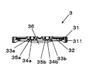
図2、図3に示すように、本実施形態では蓋体3は、2つの開口(第一開口34a、第二開口34b)を有する天板部32と、天板部32の周囲に形成される枠部材31とを備えている。
As shown in FIGS. 2 and 3, in the present embodiment, the
枠部材31は、開創器本体2の第二固定部材23と係合することで蓋体3を開創器本体2に装着する。本実施形態では、枠部材31は円環状をなしている。枠部材31の側面には、等角度間隔で4つの係合凸部311が枠部材31の中央に向かって突設されている。係合凸部311は、第二固定手段23の周面に形成された係合凹部231と係合することで蓋体3を開創器本体2に装着する。
The
枠部材31としては、第一固定部材22や第二固定部材23と同等程度の剛性を有すればいかなる材料を用いることもできる。このような材料としては例えば、ポリエチレン(PE)、ポリプロピレン(PP)などのポリオレフィン、ポリ塩化ビニル、ポリウレタン(PU)、ポリアミド(PA)、ポリアセタール、アクリロニトリル・ブタジエン・スチレン共重合体(ABS)、ポリカーボネート(PC)、水添スチレン系熱可塑性エラストマー(SEBS)、シリコーンゴムなどの樹脂材料や、ステンレス鋼などの金属材料が挙げられる。
Any material can be used for the
天板部32は、図1、図3に示すように、枠部材31により周囲を囲まれるようにして設けられている。天板部32としては処置具7の挿抜時に大きく変位しない程度の剛性を有すればいかなる材料を用いることもできる。このような材料としては例えば、軟質ポリ塩化ビニル、PU、SEBS、シリコーンゴム、天然ゴム、ニトリルゴム等の合成ゴムが挙げられる。
As shown in FIGS. 1 and 3, the
天板部32には、2つの開口(第一開口34a、第二開口34b)が形成されている。本実施形態では開口34a、34bはそれぞれ同じ大きさの円形形状をなしている。開口34a、34bは、主に処置具や光学装置等を挿入し、切開創を通して処置部に処置を施すために使用される。
なお、開口の数は2つに限られず、1つや3つ以上であってもよい。さらに、開口の形状も円形に限られず、例えば多角形であってもよく、大きさも開口ごとに異なってもよい。
The
The number of openings is not limited to two and may be one or three or more. Furthermore, the shape of the opening is not limited to a circle, and may be a polygon, for example, and the size may be different for each opening.
開口34a、34bの周囲には開口の形状が変形するのを防止するため、それぞれ開口形成部が設けられている。本実施形態では開口形成部はリング状の開口保持部材(第一開口保持部材33a、第二開口保持部材33b)である。すなわち、開口保持部材33a、33bの内側が開口34a、34bとなっている。開口保持部材33a、33bは開口形状を保持するとともに、開口34a、34bに挿入された処置具等を支持する役割も担う。
In order to prevent the shape of the opening from being deformed around the
開口保持部材33a、33bは、先端側に弁体(第一弁体35a、第二弁体35b)を備えている。弁体35a、35bは、開口34a、34bをそれぞれ覆うように設けられ、処置具等を挿入しない状態では閉じており、処置具等を挿入すると開く。本実施形態では、弁体35a、35bは、円形のシート状をなしており、中央部に十字のスリットが設けられている。なお、弁体は上述のような開閉をすればいかなる形態のものを使用してもよく、例えば、ダックビル弁やフラップ弁としてもよい。また、弁体の取付位置も開口支持部材の先端側に限られず、基端側や中間部に設けてもよく、先端部と基端部の双方に設けるなど複数の弁体を備えるようにしてもよい。
The
図2、図3に示すように、第一開口保持部材33a、第二開口保持部材33bを囲む部分にはそれぞれ支持部36が形成されている。支持部36は変形可能な程度に柔軟となっており、開口保持部材33a、33bを揺動可能に支持している。本実施形態では、支持部36は開口保持部材33a、33bを中心として天板部32を蛇腹状にして形成されている。なお、本実施形態では開口保持部材33a、33bの周囲の一部を支持部36としているが、本発明はこれに限られず、天板部32の全体を支持部36としてもよい。
なお、本実施形態では支持部として天板部を蛇腹状とすることについて説明するが、本発明はこれに限られず、支持部を他の部分よりも軟質の材料で構成してもよく、後述する第二実施形態の弾性膜体など変形可能な程度に柔軟であればいかなる形態のものでもよい。
As shown in FIGS. 2 and 3,
In the present embodiment, the top plate portion is described as having a bellows shape as the support portion, but the present invention is not limited to this, and the support portion may be made of a softer material than other portions, which will be described later. The elastic film body of the second embodiment may be of any form as long as it is flexible enough to be deformable.
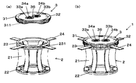
ここで、図4を参照して本実施形態における支持部36の機能について従来技術と比較して説明する。図4(a)は、本発明の第一実施形態に係る開創器1の使用状態の説明図であり、図4(b)は、従来の開創器4の使用状態の説明図である。
Here, with reference to FIG. 4, the function of the
まず、従来の開創器4の構成について簡単に説明する。開創器4は、本実施形態の開創器1と同様に筒状をなす開創器本体5と、開創器本体5に着脱自在に装着される蓋体6とを有する。そして、開創器本体5は、可撓性を有する筒状部材51と、この筒状部材51の両端に設けられた第一固定部材52および第二固定部材53、第一固定部材52と第二固定部材53の間にわたる4本のベルト(図示せず)とを備えている。
First, the configuration of the conventional retractor 4 will be briefly described. The retractor 4 includes a
さらに、従来の開創器4の蓋体6は、本実施形態の蓋体3と同様に2つの開口(第一開口63a、第二開口63b)を有する天板部62と、天板部62の周囲に形成される枠部材61とを備えている。
Further, the
本実施形態の開創器1および従来の開創器4は、腹腔内の観察、洗浄、切除、器具の留置および回収等の各種処置を補助するための器具であり、これらの処置は開口34a、34bまたは開口63a、63bに処置具等を挿入することで行う。このとき、処置部の標的部位が開口34a、34bまたは開口63a、63bの直下にあるとは限らないため、処置具7を開口34a、34bまたは開口63a、63bに対し適宜傾けて使用する場合がある。
The retractor 1 of the present embodiment and the conventional retractor 4 are instruments for assisting various procedures such as observation, washing, excision, placement and collection of instruments in the abdominal cavity, and these procedures are performed by the
このとき、従来の開創器4であれば天板部62はある程度の剛性を有しており容易に変形しない。したがって処置具7は開口63a、63bの内径と処置具7の外径との差の分または、天板部62のわずかな変形量分しか傾けることはできず、それ以上に傾斜させようとすると、天板部62に不要な力が加わり、後述する処置具7の位置ずれの問題が生じることがある。このため、開口63a、63bと処置部の位置関係によって使用可能な処置具7が制限される。
At this time, if it is the conventional retractor 4, the top-
一方、本実施形態の開創器1は、開口保持部材33a、33bを柔軟な支持部36が支持している。このため、処置具7はこれを挿入した開口保持部材33a、33bごと傾けることが可能であり、処置具7の外径が開口34a、34bの内径とほぼ等しくても自由に傾けて使用することができる。
On the other hand, in the retractor 1 of the present embodiment, the
また、図4(b)に示すように複数の開口63a、63bのそれぞれに処置具7a、7bを挿入して処置を行っている場合、従来の開創器4では一方の処置具7aを傾けたときに他方の処置具7bが追随してその位置がずれることがある。すなわち、一方の処置具7aを傾けると、これが挿入されている開口63a近傍の部分が傾く。これにより他方の開口63b近傍の部分に張力が働き、この部分も傾くと、これに挿入されている処置具7bが傾くといったことが生じうる。
Further, as shown in FIG. 4B, when treatment is performed by inserting the
一方、図4(a)に示すように、本実施形態の開創器1では、処置具7aを傾けた場合、これが挿入されている開口34a近傍の部分が傾く。しかし、開口34a(開口保持部材33a)の周囲に形成された支持部36により張力は減衰されるため、開口34b(開口保持部材33b)に張力が及ぶことが効果的に防止される。したがって、本実施形態の開創器1では、一方の開口34aに挿入した処置具7aを傾けても、他方の開口34bに挿入した処置具7bが傾くなどのずれが生じることがほとんどない。
On the other hand, as shown in FIG. 4A, in the retractor 1 of the present embodiment, when the
このように本実施形態では、開口保持部材33a、33bが支持部36により揺動可能に支持されていることにより、開口保持部材33a、33bをそれぞれ独立に動かすことが可能となっている。したがって、一方の開口保持部材33aに挿入した処置具7aの動きが他方の開口保持部材33bに挿入した処置具7bにほとんど影響を及ぼすことがなく、処置具7を自由に操作することができる。
As described above, in the present embodiment, the
ここで蓋体3の代表的な寸法について説明する。枠部材31は、外径が第二固定部材23より僅かに大きく45〜135mm程度、内径が40〜120mm程度であり、厚さが5〜20mm程度である。また、天板部32は厚さが0.5〜5mm程度であり、凹没した部分の大きさは直径が35〜115mm程度、深さが5〜35mm程度である。さらに、開口34a、34bは直径が2〜15mm程度となっている。
Here, typical dimensions of the
次に、本実施形態に係る開創器1の使用方法について説明する。本実施形態の開創器1は、主に腹腔内の処置に用いられる。まず、腹部に切開創を形成する。切開創は一文字状や十字状など様々に形成してもよい。この切開創を介して腹腔内に開創器本体2の第一固定部材22を挿入する。次いで、第二固定部材23を持ち上げ第一固定部材22を腹壁の裏面に密着させた状態でベルト24を1本ずつ牽引する。これにより切開創をより大きく開創できるとともに、第一固定部材22と第二固定部材23とで腹壁を挟み込むことで開創器本体2が切開創に固定設置される。
Next, the usage method of the retractor 1 which concerns on this embodiment is demonstrated. The retractor 1 of this embodiment is mainly used for treatment in the abdominal cavity. First, an incision is formed in the abdomen. The incision may be variously formed such as a single letter or a cross. The first fixing
開創器本体2を介して体内の処置を行う。気腹操作を行う場合は蓋体3を装着する。蓋体3の装着は、蓋体3を第二固定部材23の上に置き、右回しに約45度回転させることで行う。これにより蓋体3の係合凸部311と第二固定部材23の係合凹部231が係合し、蓋体3が開創器本体2に固定される。なお、取り外す場合は蓋体3を左回しに約45度回転させればよい。
An internal treatment is performed via the
蓋体3を装着した状態で体内の処置を行う場合には開口34a、34bを介して行う。使用される処置具7としては、例えば把持用の鉗子、切除用のメス、補助用の鉗子、光学装置またはこれらを挿通するためのトロッカーなどが挙げられる。これらの処置具7を開口34a、34bに挿入して体内の処置を行う。
When the treatment inside the body is performed with the
このとき本実施形態の開創器1では、開口34a、34b(開口保持部材33a、33b)はそれぞれ周囲に柔軟な支持部36を備えている。したがって、前述のように一方の開口34aに挿入された処置具7を傾斜させる等操作しても、その動きの他方の開口34bに挿入された処置具7への影響が小さく、他方側の処置具7が不測に動くことが防止され、処置をより円滑に行うことができる。
At this time, in the retractor 1 of the present embodiment, the
本実施形態の開創器本体2を取りだすときは、まずベルト24の下にある解除レバー(図示せず)を押し下げる。この状態のまま鉗子等でベルト24が第二固定部材23から完全に外れるまで引き戻す。その後、ベルト24を引き上げ第一固定部材22を抜去する。
When taking out the
<第二実施形態>
次に本発明の第二実施形態について説明する。
以下では、第二実施形態について説明するが、第一実施形態との相違点を中心に説明し、同様の事項についてはその説明を省略する。
<Second embodiment>
Next, a second embodiment of the present invention will be described.
In the following, the second embodiment will be described, but the difference from the first embodiment will be mainly described, and the description of the same matters will be omitted.
図5は、本発明の第二実施形態に係る蓋体の断面図である。
第二実施形態では、蓋体3の構成が異なる以外は第一実施形態と同様である。
FIG. 5 is a cross-sectional view of a lid according to the second embodiment of the present invention.
The second embodiment is the same as the first embodiment except that the configuration of the
図5に示すように、本実施形態では天板部32は、蓋体3を開創器本体2に装着したときに開創器本体2の内側に向かって凹没する部分を有しており、凹没する部分の底部に開口34a、34bが形成されている。本実施形態では、図5に示すように、天板部31全体が凹没している。そして、凹没する部分の底部は枠部材31と平行になっているが、平行とは限られず曲面状等でもよい。なお、凹没する部分は天板部の全体に限られず、少なくとも開口を囲む部分において凹没していればよく、開口が複数ある場合には開口ごとに複数の凹没する部分を有していてもよい。
As shown in FIG. 5, in this embodiment, the
ここで、図6を参照して本実施形態における開口34a、34bの機能について従来技術と比較して説明する。図6(a)は、本発明の第二実施形態に係る開創器1を使用した場合の処置具7の可動域を説明した図であり、図6(b)は、従来の開創器4を使用した場合の処置具7の可動域を説明した図である。
Here, the functions of the
前述のように開創器1または開創器4を介した処置においては、処置具7を開口34a、34bまたは開口63a、63bに対して傾けて使用する場合がある。この場合、傾ける方向によって処置具7をどの程度傾けることができるかは異なる。特に処置具7を外側に向けて傾けるときに最も傾斜角を取ることができない。この場合、図6に示すように処置具7が第一固定部材22または第一固定部材52と当接するまでしか傾けることができず、処置具7の可動範囲が制限される。
As described above, in the treatment via the retractor 1 or the retractor 4, the treatment instrument 7 may be used while being inclined with respect to the
開創器本体2または開創器本体5の第一固定部材22または52および第二固定部材23または53はベルト24を牽引することで腹壁の裏面と表面に密着している。したがって、第一固定部材22または52から第二固定部材23または53までの距離は患者の腹壁の厚さによって決まる。ここで、図6(b)に示すように、従来の開創器4は開口63a、63bが第二固定部材53と同一平面内に形成されているため、開口63a、63bから第一固定部材52までの距離が長くなる。このため、従来の開創器4では処置具7をあまり大きく傾けることができない。
The first fixing
一方、図6(a)に示すように、本実施形態の開創器1の開口34a、34bは蓋体を開創器本体2に装着したときに開創器本体2の端部(第二固定部材23)よりも内側に位置するよう形成されている。したがって、開口34a、34bから第一固定部材22までの距離は短くなり、処置具7を大きく傾けることができる。
On the other hand, as shown in FIG. 6 (a), the
より詳細に説明する。図6(a)、(b)に示すように、第二固定部材23、53から第一開口34a、63aの中心までの距離をa、第一開口34aの中心から第一固定部材22までの高さをb、第一開口63aの中心から第一固定部材52までの高さをcとし、第一開口34aに挿入した処置具7の最大傾斜角度をθA、第一開口63aに挿入した処置具7の最大傾斜角度をθBとする。このとき、θA=arcsin(a/b)、θB=arcsin(a/c)であり、b<cからθA>θBとなる。すなわち、平面視で同じ位置にある開口であれば、本実施形態の開創器1は従来の開創器4と比べて処置具7を大きく傾けることが可能となる。したがって、本実施形態の開創器1は処置具7の可動範囲を広くとることができる。
This will be described in more detail. 6A and 6B, the distance from the
さらに、処置具7を開口34a、34bに挿入して処置を行う場合、処置具は開口34a、34bを支点として操作される。このとき本実施形態の開創器1では開口34a、34bから処置部までの距離が短いため、従来の開創器4と比べてより繊細な操作が可能となる。
Furthermore, when the treatment tool 7 is inserted into the
また、本実施形態では支持部36は弾性膜体により形成されている。すなわち、開口保持部材33a、33bは弾性膜体により支持されている。この弾性膜体は第一実施形態の蛇腹状の支持部36と同様に開口保持部材33a、33bを揺動可能に支持する。したがって、本実施形態においても、開口保持部材33a、33bをそれぞれ独立に動かすことが可能となっており、一方の開口保持部材33aに挿入した処置具7aの動きが他方の開口保持部材33bに挿入した処置具7bにほとんど影響を及ぼすことがなく、処置具7を自由に操作することができる。
In the present embodiment, the
このような弾性膜体の材料としては、例えばポリウレタン(PU)、水添スチレン系熱可塑性エラストマー(SEBS)、シリコーンゴム、天然ゴム、ニトリルゴム等の合成ゴムが挙げられる。 Examples of the material for such an elastic membrane include synthetic rubbers such as polyurethane (PU), hydrogenated styrene thermoplastic elastomer (SEBS), silicone rubber, natural rubber, and nitrile rubber.
なお、本実施形態では支持部として弾性膜体を挙げたが、本発明はこれに限られず、例えば前述の第一実施形態の蛇腹など変形可能な程度に柔軟であればいかなる形態のものでもよい。 In the present embodiment, the elastic film body is exemplified as the support portion. However, the present invention is not limited to this, and any form may be used as long as it is flexible enough to be deformed, such as the bellows of the first embodiment described above. .
1 開創器
2 開創器本体
21 筒状部材
22 第一固定部材
23 第二固定部材
231 係合凹部
24 ベルト
3 蓋体
31 枠部材
311 係合凸部
32 天板部
33a 第一開口保持部材
33b 第二開口保持部材
34a 第一開口
34b 第二開口
35a 第一弁体
35b 第二弁体
36 支持部
37 基端側円環部
38 先端側円環部
39 円筒部
4 開創器
5 開創器本体
51 筒状部材
52 第一固定部材
53 第二固定部材
6 蓋体
61 枠部材
62 天板部
63a 第一開口
63b 第二開口
7、7a、7b 処置具
DESCRIPTION OF SYMBOLS 1
Claims (8)
前記蓋体は、少なくとも1つの開口を有する開口形成部と、前記開口形成部を揺動可能に支持する支持部とを備えることを特徴とする蓋体。 A lid that is detachably attached to a retractor body having a cylindrical shape,
The said cover body is provided with the opening formation part which has at least 1 opening, and the support part which supports the said opening formation part so that rocking | fluctuation is possible.
Priority Applications (1)
| Application Number | Priority Date | Filing Date | Title |
|---|---|---|---|
| JP2012070826A JP2013202074A (en) | 2012-03-27 | 2012-03-27 | Lid and retractor having the same |
Applications Claiming Priority (1)
| Application Number | Priority Date | Filing Date | Title |
|---|---|---|---|
| JP2012070826A JP2013202074A (en) | 2012-03-27 | 2012-03-27 | Lid and retractor having the same |
Publications (1)
| Publication Number | Publication Date |
|---|---|
| JP2013202074A true JP2013202074A (en) | 2013-10-07 |
Family
ID=49521839
Family Applications (1)
| Application Number | Title | Priority Date | Filing Date |
|---|---|---|---|
| JP2012070826A Pending JP2013202074A (en) | 2012-03-27 | 2012-03-27 | Lid and retractor having the same |
Country Status (1)
| Country | Link |
|---|---|
| JP (1) | JP2013202074A (en) |
Cited By (2)
| Publication number | Priority date | Publication date | Assignee | Title |
|---|---|---|---|---|
| CN106137282A (en) * | 2016-05-16 | 2016-11-23 | 杨雪鹰 | A kind of single hole thoracoscopic operation operating platform |
| CN106236158A (en) * | 2016-05-16 | 2016-12-21 | 杨雪鹰 | A kind of single hole thoracoscope otch separates holder |
Citations (3)
| Publication number | Priority date | Publication date | Assignee | Title |
|---|---|---|---|---|
| JP2006150132A (en) * | 2006-03-15 | 2006-06-15 | Hakko Co Ltd | Insertion port for medical treatment instrument |
| JP2010082449A (en) * | 2008-09-30 | 2010-04-15 | Ethicon Endo Surgery Inc | Surgical access device |
| JP2010207578A (en) * | 2009-03-06 | 2010-09-24 | Ethicon Endo Surgery Inc | Surgical access devices and methods providing seal movement in predefined paths |
-
2012
- 2012-03-27 JP JP2012070826A patent/JP2013202074A/en active Pending
Patent Citations (3)
| Publication number | Priority date | Publication date | Assignee | Title |
|---|---|---|---|---|
| JP2006150132A (en) * | 2006-03-15 | 2006-06-15 | Hakko Co Ltd | Insertion port for medical treatment instrument |
| JP2010082449A (en) * | 2008-09-30 | 2010-04-15 | Ethicon Endo Surgery Inc | Surgical access device |
| JP2010207578A (en) * | 2009-03-06 | 2010-09-24 | Ethicon Endo Surgery Inc | Surgical access devices and methods providing seal movement in predefined paths |
Cited By (2)
| Publication number | Priority date | Publication date | Assignee | Title |
|---|---|---|---|---|
| CN106137282A (en) * | 2016-05-16 | 2016-11-23 | 杨雪鹰 | A kind of single hole thoracoscopic operation operating platform |
| CN106236158A (en) * | 2016-05-16 | 2016-12-21 | 杨雪鹰 | A kind of single hole thoracoscope otch separates holder |
Similar Documents
| Publication | Publication Date | Title |
|---|---|---|
| EP2055250B1 (en) | Surgical hand access apparatus | |
| KR101022754B1 (en) | Multi-channel troca equipped with wound retractor | |
| JP4796573B2 (en) | Trocar seal | |
| CA2698059C (en) | Access devices | |
| US8226553B2 (en) | Access device with insert | |
| US8353824B2 (en) | Access method with insert | |
| EP2672905B1 (en) | Surgical device | |
| US20120157786A1 (en) | Surgical retractor having ring of variable durometer | |
| US20110245619A1 (en) | Surgical access device | |
| US8197404B2 (en) | Handoscopy interwoven layered seal laparoscopic disk | |
| US10307151B2 (en) | Retractor for surgical operation | |
| KR20100114462A (en) | Cannula with sealing elements | |
| KR20100100706A (en) | Surgical access devices and methods providing seal movement in predefined paths | |
| KR20040025699A (en) | Medical treating instrument | |
| US8002786B2 (en) | Hand assisted laparoscopic seal assembly with deflection feature | |
| JP2010523221A (en) | Hand assisted laparoscopic seal assembly with removable attachment ring | |
| JP2013202074A (en) | Lid and retractor having the same | |
| JP5794319B2 (en) | Medical treatment tool | |
| JP2013202075A (en) | Lid and retractor having the same | |
| JP4623067B2 (en) | Medical treatment tool | |
| US11406420B2 (en) | Two point contact flange for instrument seals | |
| JP2006142037A (en) | Medical treatment instrument | |
| JP2018096436A (en) | Duckbill valve | |
| JP4082952B2 (en) | Medical treatment tool | |
| JP5813849B2 (en) | Medical instrument insertion device |
Legal Events
| Date | Code | Title | Description |
|---|---|---|---|
| A621 | Written request for application examination |
Free format text: JAPANESE INTERMEDIATE CODE: A621 Effective date: 20141114 |
|
| A977 | Report on retrieval |
Free format text: JAPANESE INTERMEDIATE CODE: A971007 Effective date: 20150722 |
|
| A131 | Notification of reasons for refusal |
Free format text: JAPANESE INTERMEDIATE CODE: A131 Effective date: 20150804 |
|
| A02 | Decision of refusal |
Free format text: JAPANESE INTERMEDIATE CODE: A02 Effective date: 20151201 |