JP2013103094A - Measurement device, measurement method, program, and recording medium - Google Patents
Measurement device, measurement method, program, and recording medium Download PDFInfo
- Publication number
- JP2013103094A JP2013103094A JP2011250998A JP2011250998A JP2013103094A JP 2013103094 A JP2013103094 A JP 2013103094A JP 2011250998 A JP2011250998 A JP 2011250998A JP 2011250998 A JP2011250998 A JP 2011250998A JP 2013103094 A JP2013103094 A JP 2013103094A
- Authority
- JP
- Japan
- Prior art keywords
- measurement
- light
- living body
- light source
- vivo
- Prior art date
- Legal status (The legal status is an assumption and is not a legal conclusion. Google has not performed a legal analysis and makes no representation as to the accuracy of the status listed.)
- Pending
Links
Images


Classifications
-
- A—HUMAN NECESSITIES
- A61—MEDICAL OR VETERINARY SCIENCE; HYGIENE
- A61B—DIAGNOSIS; SURGERY; IDENTIFICATION
- A61B5/00—Measuring for diagnostic purposes; Identification of persons
- A61B5/0059—Measuring for diagnostic purposes; Identification of persons using light, e.g. diagnosis by transillumination, diascopy, fluorescence
- A61B5/0077—Devices for viewing the surface of the body, e.g. camera, magnifying lens
-
- A—HUMAN NECESSITIES
- A61—MEDICAL OR VETERINARY SCIENCE; HYGIENE
- A61B—DIAGNOSIS; SURGERY; IDENTIFICATION
- A61B5/00—Measuring for diagnostic purposes; Identification of persons
- A61B5/0059—Measuring for diagnostic purposes; Identification of persons using light, e.g. diagnosis by transillumination, diascopy, fluorescence
- A61B5/0075—Measuring for diagnostic purposes; Identification of persons using light, e.g. diagnosis by transillumination, diascopy, fluorescence by spectroscopy, i.e. measuring spectra, e.g. Raman spectroscopy, infrared absorption spectroscopy
-
- A—HUMAN NECESSITIES
- A61—MEDICAL OR VETERINARY SCIENCE; HYGIENE
- A61B—DIAGNOSIS; SURGERY; IDENTIFICATION
- A61B5/00—Measuring for diagnostic purposes; Identification of persons
- A61B5/145—Measuring characteristics of blood in vivo, e.g. gas concentration, pH value; Measuring characteristics of body fluids or tissues, e.g. interstitial fluid, cerebral tissue
- A61B5/1455—Measuring characteristics of blood in vivo, e.g. gas concentration, pH value; Measuring characteristics of body fluids or tissues, e.g. interstitial fluid, cerebral tissue using optical sensors, e.g. spectral photometrical oximeters
-
- A—HUMAN NECESSITIES
- A61—MEDICAL OR VETERINARY SCIENCE; HYGIENE
- A61B—DIAGNOSIS; SURGERY; IDENTIFICATION
- A61B5/00—Measuring for diagnostic purposes; Identification of persons
- A61B5/44—Detecting, measuring or recording for evaluating the integumentary system, e.g. skin, hair or nails
- A61B5/441—Skin evaluation, e.g. for skin disorder diagnosis
- A61B5/443—Evaluating skin constituents, e.g. elastin, melanin, water
-
- A—HUMAN NECESSITIES
- A61—MEDICAL OR VETERINARY SCIENCE; HYGIENE
- A61B—DIAGNOSIS; SURGERY; IDENTIFICATION
- A61B5/00—Measuring for diagnostic purposes; Identification of persons
- A61B5/72—Signal processing specially adapted for physiological signals or for diagnostic purposes
-
- A—HUMAN NECESSITIES
- A61—MEDICAL OR VETERINARY SCIENCE; HYGIENE
- A61B—DIAGNOSIS; SURGERY; IDENTIFICATION
- A61B5/00—Measuring for diagnostic purposes; Identification of persons
- A61B5/145—Measuring characteristics of blood in vivo, e.g. gas concentration, pH value; Measuring characteristics of body fluids or tissues, e.g. interstitial fluid, cerebral tissue
- A61B5/14532—Measuring characteristics of blood in vivo, e.g. gas concentration, pH value; Measuring characteristics of body fluids or tissues, e.g. interstitial fluid, cerebral tissue for measuring glucose, e.g. by tissue impedance measurement
-
- A—HUMAN NECESSITIES
- A61—MEDICAL OR VETERINARY SCIENCE; HYGIENE
- A61B—DIAGNOSIS; SURGERY; IDENTIFICATION
- A61B5/00—Measuring for diagnostic purposes; Identification of persons
- A61B5/145—Measuring characteristics of blood in vivo, e.g. gas concentration, pH value; Measuring characteristics of body fluids or tissues, e.g. interstitial fluid, cerebral tissue
- A61B5/14542—Measuring characteristics of blood in vivo, e.g. gas concentration, pH value; Measuring characteristics of body fluids or tissues, e.g. interstitial fluid, cerebral tissue for measuring blood gases
Landscapes
- Health & Medical Sciences (AREA)
- Life Sciences & Earth Sciences (AREA)
- Physics & Mathematics (AREA)
- Engineering & Computer Science (AREA)
- Public Health (AREA)
- Surgery (AREA)
- Veterinary Medicine (AREA)
- General Health & Medical Sciences (AREA)
- Animal Behavior & Ethology (AREA)
- Biophysics (AREA)
- Pathology (AREA)
- Biomedical Technology (AREA)
- Heart & Thoracic Surgery (AREA)
- Medical Informatics (AREA)
- Molecular Biology (AREA)
- Spectroscopy & Molecular Physics (AREA)
- Optics & Photonics (AREA)
- Dermatology (AREA)
- Psychiatry (AREA)
- Computer Vision & Pattern Recognition (AREA)
- Physiology (AREA)
- Artificial Intelligence (AREA)
- Signal Processing (AREA)
- Measurement Of The Respiration, Hearing Ability, Form, And Blood Characteristics Of Living Organisms (AREA)
- Investigating Or Analysing Materials By Optical Means (AREA)
Abstract
Description
本開示は、測定装置、測定方法、プログラム及び記録媒体に関する。 The present disclosure relates to a measuring apparatus, a measuring method, a program, and a recording medium.
生体の皮下に存在する体内物質を、紫外光〜ミリ波等の各種電磁波や超音波等を用いて非侵襲で計測する技術に関する研究が進んでいる。例えば、以下の特許文献1には、近赤外光を用いて血糖値を非侵襲に測定する方法及び装置について、開示されている。
Research is progressing on techniques for non-invasively measuring in-vivo substances existing under the skin of a living body using various electromagnetic waves such as ultraviolet light to millimeter waves, ultrasonic waves, and the like. For example,
しかしながら、上記特許文献1等に記載されているような、非侵襲の光学測定を用いた体内計測技術では、各個人の有する体質差等による影響が、計測精度を著しく阻害してしまう。例えば、ラマン分光や近赤外分光等の分光法や、紫外線励起による蛍光分析等を用いて、体内のグルコースやアルブミン、AGEs(Advanced Glycation Endproducts:糖化最終産物)等の計測を目的とする装置では、計測者本人の経時変化、肥満、日焼け等や、人種の差、体質の差等は、光学計測を行う際の誤差要因となってしまう。また、グルコース、AGEs等の光計測は一般的に多変量解析であり、光学モデルの変動に対応できない。
However, in the in-vivo measurement technique using non-invasive optical measurement as described in the above-mentioned
そのため、計測者本人に由来する誤差要因に関する変動成分量を、着目する生体物質の計測に先立って特定することができれば、光学モデルの変動を推定することが可能となり、ひいては体内計測技術の信頼性を向上させることが可能となる。 Therefore, if it is possible to identify the fluctuation component amount related to the error factor derived from the measurer prior to the measurement of the biological substance of interest, it is possible to estimate the fluctuation of the optical model, and thus the reliability of the in-vivo measurement technology. Can be improved.
そこで、本開示では、上記事情に鑑みて、光学モデルの変動をもたらしうる生体内成分を正確に測定することが可能な、測定装置、測定方法、プログラム及び記録媒体を提案する。 Therefore, in view of the above circumstances, the present disclosure proposes a measuring apparatus, a measuring method, a program, and a recording medium that can accurately measure in-vivo components that can cause fluctuations in the optical model.
本開示によれば、生体内に存在する生体内成分を測定するために用いられ、所定の波長帯域に属する測定光を、前記生体に向かって射出する光源と、複数のセンサが所定の配置で規則的に配設されており、前記光源から射出され前記生体を透過した前記測定光を当該複数のセンサで検出する検出部と、前記検出部により検出された検出結果を利用し、前記光源からの光学的距離に応じて減衰した光量に基づいて前記生体内成分の成分量を解析する解析部と、を備える測定装置が提供される。 According to the present disclosure, a light source that emits measurement light belonging to a predetermined wavelength band, which is used to measure in-vivo components existing in a living body, toward the living body, and a plurality of sensors are arranged in a predetermined arrangement. The detection unit is arranged regularly, detects the measurement light emitted from the light source and transmitted through the living body by the plurality of sensors, and uses the detection result detected by the detection unit, from the light source There is provided a measuring device including an analysis unit that analyzes the amount of the in-vivo component based on the amount of light attenuated according to the optical distance.
また、本開示によれば、生体内に存在する生体内成分を測定するために用いられ、所定の波長帯域に属する測定光を、前記生体に向かって射出することと、前記生体を透過した前記測定光を、複数のセンサが所定の配置で規則的に配設された検出ユニットで検出することと、検出された検出結果を利用し、前記測定光の光源からの光学的距離に応じて減衰した光量に基づいて前記生体内成分の成分量を解析することと、を含む測定方法が提供される。 Further, according to the present disclosure, it is used to measure in-vivo components existing in a living body, and the measurement light belonging to a predetermined wavelength band is emitted toward the living body, and the permeated through the living body The measurement light is detected by a detection unit in which a plurality of sensors are regularly arranged in a predetermined arrangement, and the detection result is used to attenuate the measurement light according to the optical distance from the light source. Analyzing the component amount of the in-vivo component based on the amount of light emitted.
また、本開示によれば、生体内に存在する生体内成分を測定するために用いられ、所定の波長帯域に属する測定光を、前記生体に向かって射出する光源と、複数のセンサが所定の配置で規則的に配設されており、前記光源から射出され前記生体を透過した前記測定光を当該複数のセンサで検出する検出部と、を備える測定機器を制御可能なコンピュータに、前記光源及び前記検出部を制御する制御機能と、前記検出部により検出された検出結果を利用し、前記光源からの光学的距離に応じて減衰した光量に基づいて前記生体内成分の成分量を解析する解析機能と、を実現させるためのプログラムが提供される。 In addition, according to the present disclosure, a light source that is used to measure in-vivo components existing in a living body and emits measurement light belonging to a predetermined wavelength band toward the living body, and a plurality of sensors are provided A computer that is capable of controlling a measuring instrument, the detector having a plurality of sensors that detect the measurement light emitted from the light source and transmitted through the living body. Analysis that analyzes the component amount of the in-vivo component based on the amount of light attenuated according to the optical distance from the light source using the control function for controlling the detection unit and the detection result detected by the detection unit And a program for realizing the functions.
また、本開示によれば、生体内に存在する生体内成分を測定するために用いられ、所定の波長帯域に属する測定光を、前記生体に向かって射出する光源と、複数のセンサが所定の配置で規則的に配設されており、前記光源から射出され前記生体を透過した前記測定光を当該複数のセンサで検出する検出部と、を備える測定機器を制御可能なコンピュータに、前記光源及び前記検出部を制御する制御機能と、前記検出部により検出された検出結果を利用し、前記光源からの光学的距離に応じて減衰した光量に基づいて前記生体内成分の成分量を解析する解析機能と、を実現させるためのプログラムが記録された記録媒体が提供される。 In addition, according to the present disclosure, a light source that is used to measure in-vivo components existing in a living body and emits measurement light belonging to a predetermined wavelength band toward the living body, and a plurality of sensors are provided A computer that is capable of controlling a measuring instrument, the detector having a plurality of sensors that detect the measurement light emitted from the light source and transmitted through the living body. Analysis that analyzes the component amount of the in-vivo component based on the amount of light attenuated according to the optical distance from the light source using the control function for controlling the detection unit and the detection result detected by the detection unit And a recording medium on which a program for realizing the functions is recorded is provided.
また、本開示によれば、生体に含まれる計測対象物質を計測する生体物質計測装置と、前記生体内に存在する前記計測対象物質とは異なる生体内成分を測定するために用いられ、所定の波長帯域に属する測定光を、前記生体に向かって射出する光源と、複数のセンサが所定の配置で規則的に配設されており、前記光源から射出され前記生体を透過した前記測定光を当該複数のセンサで検出する検出部と、前記検出部により検出された検出結果を利用し、前記光源からの光学的距離に応じて減衰した光量に基づいて前記生体内成分の成分量を解析する解析部と、を備える測定装置が提供される。 In addition, according to the present disclosure, a biological material measurement device that measures a measurement target substance contained in a living body, and a living body component that is different from the measurement target substance present in the living body are used. A light source for emitting measurement light belonging to a wavelength band toward the living body and a plurality of sensors are regularly arranged in a predetermined arrangement, and the measurement light emitted from the light source and transmitted through the living body is Analysis that analyzes the component amount of the in-vivo component based on the amount of light attenuated according to the optical distance from the light source using the detection unit detected by a plurality of sensors and the detection result detected by the detection unit And a measurement device including the unit.
また、本開示によれば、生体に含まれる計測対象物質を計測する生体物質計測装置と、前記生体内に存在する前記計測対象物質とは異なる生体内成分を測定するために用いられ、所定の波長帯域に属する測定光を、前記生体に向かって射出する光源と、複数のセンサが所定の配置で規則的に配設されており、前記光源から射出され前記生体を透過した前記測定光を当該複数のセンサで検出する検出部と、前記検出部により検出された検出結果を利用し、前記光源からの光学的距離に応じて減衰した光量に基づいて前記生体内成分の成分量を解析する解析部と、を備え、前記生体物質計測装置又は前記解析部は、前記生体物質計測装置における計測結果を、前記生体内成分の成分量を利用して補正する測定装置が提供される。 In addition, according to the present disclosure, a biological material measurement device that measures a measurement target substance contained in a living body, and a living body component that is different from the measurement target substance present in the living body are used. A light source for emitting measurement light belonging to a wavelength band toward the living body and a plurality of sensors are regularly arranged in a predetermined arrangement, and the measurement light emitted from the light source and transmitted through the living body is Analysis that analyzes the component amount of the in-vivo component based on the amount of light attenuated according to the optical distance from the light source using the detection unit detected by a plurality of sensors and the detection result detected by the detection unit A measurement device that corrects a measurement result in the biological material measurement device using a component amount of the in-vivo component.
本開示によれば、光源は、生体内に存在する生体内成分を測定するために用いられ、所定の波長帯域に属する測定光を生体に向かって射出し、複数のセンサが所定の配置で規則的に配設された検出部は、光源から射出され生体を透過した測定光を検出し、解析部は、検出部により検出された検出結果を利用し、光源からの光学的距離に応じて減衰した光量に基づいて、生体内成分の成分量を解析する。 According to the present disclosure, the light source is used to measure in-vivo components existing in the living body, emits measurement light belonging to a predetermined wavelength band toward the living body, and a plurality of sensors are arranged in a predetermined arrangement. The detection unit arranged in the detector detects measurement light emitted from the light source and transmitted through the living body, and the analysis unit uses the detection result detected by the detection unit and attenuates according to the optical distance from the light source. The component amount of the in-vivo component is analyzed on the basis of the light amount.
以上説明したように本開示によれば、光学モデルの変動をもたらしうる生体内成分を正確に測定することが可能となる。 As described above, according to the present disclosure, it is possible to accurately measure in-vivo components that may cause fluctuations in the optical model.
以下に添付図面を参照しながら、本開示の好適な実施の形態について詳細に説明する。なお、本明細書及び図面において、実質的に同一の機能構成を有する構成要素については、同一の符号を付することにより重複説明を省略する。 Hereinafter, preferred embodiments of the present disclosure will be described in detail with reference to the accompanying drawings. In addition, in this specification and drawing, about the component which has the substantially same function structure, duplication description is abbreviate | omitted by attaching | subjecting the same code | symbol.
なお、説明は、以下の順序で行うものとする。
(1)人体の皮膚構造モデルについて
(2)第1の実施形態
(2−1)測定装置の構成について
(2−2)変形例
(3)本開示の実施形態に係る測定装置のハードウェア構成について
(4)まとめ
The description will be made in the following order.
(1) Human skin structure model (2) First embodiment (2-1) Configuration of measurement device (2-2) Modification (3) Hardware configuration of measurement device according to embodiment of present disclosure (4) Summary
(人体の皮膚構造モデルについて)
本開示の実施形態に係る測定装置、測定方法及びプログラムについて説明するに先立ち、人体の皮膚構造をモデル化した皮膚構造モデルについて、図1を参照しながら簡単に説明する。図1は、人体の皮膚構造モデルの例を示した説明図である。
(About the human skin structure model)
Prior to describing the measurement apparatus, the measurement method, and the program according to the embodiment of the present disclosure, a skin structure model obtained by modeling the skin structure of a human body will be briefly described with reference to FIG. FIG. 1 is an explanatory view showing an example of a human skin structure model.
近年、人体内に存在するグルコース、アルブミン、AGEs(糖化最終産物)、コレステロール、酸化・還元ヘモグロビン等の血中・体液成分や、メラニン、脂肪等を非侵襲の光学測定により計測する技術が開発されている。このような体内計測技術は、ラマン分光や近赤外分光等の分光法を用いたり、屈折率の変化を計測したり、紫外光〜ミリ波等の各種電磁波を用いたり、超音波を用いたりすることで実施され、測定されたデータの解析には、多変量解析の使用が主流となっている。 In recent years, technology has been developed to measure blood and body fluid components such as glucose, albumin, AGEs (end glycation end products), cholesterol, oxidized / reduced hemoglobin, melanin, fat, etc. present in the human body by noninvasive optical measurement. ing. Such in-vivo measurement technology uses Raman spectroscopy, near-infrared spectroscopy, etc., measures changes in refractive index, uses various electromagnetic waves such as ultraviolet light to millimeter waves, and uses ultrasonic waves. The use of multivariate analysis is the mainstream for the analysis of measured and measured data.
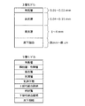
測定されたデータを解析するにあたっては、人体の皮膚構造をどのようにモデル化するかが重要となってくる。このような人体の皮膚構造モデルの例としては、図1に示したような3層モデルや9層モデルが存在する。 In analyzing the measured data, it is important how to model the human skin structure. Examples of such a human skin structure model include a three-layer model and a nine-layer model as shown in FIG.
図1に示した3層モデルは、皮膚の角質層より下部に位置する皮下組織を、表皮層、真皮層、皮下脂肪の3つの層にモデル化したものである。この3層モデルにおいて、角質層は、個人差はあるものの体表から内部方向に0.01〜0.02mm程度に相当し、表皮層は、体表から0.04〜0.15mm程度に相当し、真皮層は、体表から1〜4mm程度に相当し、皮下脂肪は、体表から数mm〜数cm程度に相当する。 The three-layer model shown in FIG. 1 models the subcutaneous tissue located below the stratum corneum of the skin into three layers of the epidermis layer, the dermis layer, and the subcutaneous fat. In this three-layer model, the stratum corneum corresponds to about 0.01 to 0.02 mm in the internal direction from the body surface although there are individual differences, and the epidermis layer corresponds to about 0.04 to 0.15 mm from the body surface. The dermal layer corresponds to about 1 to 4 mm from the body surface, and the subcutaneous fat corresponds to about several mm to several cm from the body surface.
また、図1に示した9層モデルは、人体の皮膚構造をより詳細に区分したものであり、角質層から皮下組織まで、人体の皮膚構造が9層から構成されるとしてモデル化したものである。 The 9-layer model shown in FIG. 1 is a more detailed classification of the human skin structure, and is modeled on the assumption that the human skin structure is composed of 9 layers from the stratum corneum to the subcutaneous tissue. is there.
このような皮膚構造において、メラニンという体内成分は、主に表皮層に存在しており、場合によっては基底層に存在することがある。また、3層モデルにおける真皮層には、毛細血管が存在しており、この毛細血管の内部には、酸化ヘモグロビン、還元ヘモグロビンや、各種の血中成分が存在している。また、3層モデルにおける皮下脂肪や、9層モデルにおける皮下組織には、主に脂肪細胞が存在している。従って、上記のような成分を非侵襲の光学測定により計測する場合には、どのような皮膚構造モデルを考慮するかが重要になるのである。 In such a skin structure, a body component called melanin is mainly present in the epidermis layer, and in some cases may be present in the basal layer. Further, capillaries are present in the dermis layer in the three-layer model, and oxygenated hemoglobin, reduced hemoglobin, and various blood components are present inside the capillaries. In addition, fat cells are mainly present in the subcutaneous fat in the 3-layer model and the subcutaneous tissue in the 9-layer model. Therefore, when measuring the above components by noninvasive optical measurement, it is important to consider what skin structure model is taken into consideration.
ところが、人体の皮膚構造や、皮膚構造に含まれる各種体内成分は、被測定者本人の経年変化、肥満、日焼け、人種の差、性別、体質等により変動するものであり、個人差も大きいものである。また、毛細血管等の位置については、お湯を浴びることによっても微妙に変化することが知られている。このため、皮膚構造モデルに基づく体内成分の非侵襲計測では、図1に示したような皮膚構造モデルの変動の影響を強く受けるものであると言える。 However, the skin structure of the human body and various body components contained in the skin structure vary depending on the subject's aging, obesity, sunburn, race, gender, constitution, etc. Is. In addition, it is known that the position of capillaries and the like slightly changes even when bathing in hot water. For this reason, it can be said that the non-invasive measurement of the in-vivo components based on the skin structure model is strongly influenced by the fluctuation of the skin structure model as shown in FIG.
しかしながら、現在提案されている生体物質の非侵襲計測方法は、上記のような皮膚構造モデルの変動を考慮しておらず、計測結果には、上記のような変動に由来する誤差が重畳していると考えられる。そのため、本発明者は、以上のような事情を鑑みて、被測定者個人の有する体質差等に起因する計測結果への影響を補正することが可能な技術について鋭意検討を行った。その結果、本発明者は、以下で説明するような本開示の実施形態に係る測定装置及び測定方法に想到した。 However, the currently proposed non-invasive measurement method of biological material does not consider the variation of the skin structure model as described above, and an error derived from the variation as described above is superimposed on the measurement result. It is thought that there is. Therefore, in view of the circumstances as described above, the present inventor has intensively studied a technique capable of correcting the influence on the measurement result caused by the constitutional difference of the individual to be measured. As a result, the present inventor has conceived a measurement apparatus and a measurement method according to an embodiment of the present disclosure as described below.
(第1の実施形態)
<測定装置の構成について>
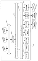
続いて、図2〜図7を参照しながら、本開示の第1の実施形態に係る測定装置及び測定方法について、詳細に説明する。図2は、本実施形態に係る測定装置10の構成について示したブロック図である。図3は、本実施形態に係る測定装置10が備える測定部の一例を示した説明図である。図4は、本実施形態に係る測定装置10について説明するための説明図である。図5は、拡張ランベルト・ベールの法則について説明するための説明図である。図6A〜図6Cは、生体内成分の光吸収スペクトルの例を示したグラフ図である。図7は、本実施形態に係る測定装置10で用いられる減衰カーブの一例を示したグラフ図である。
(First embodiment)
<About the configuration of the measuring device>
Subsequently, the measurement apparatus and the measurement method according to the first embodiment of the present disclosure will be described in detail with reference to FIGS. FIG. 2 is a block diagram showing the configuration of the measuring
まず、図2を参照しながら、本実施形態に係る測定装置10の全体構成について、詳細に説明する。
本実施形態に係る測定装置10は、測定対象物である生体Bを所定の波長を有する光を用いて測定し、得られた測定結果に基づいて生体Bに含まれる生体内成分の成分量を算出する装置である。この測定装置10は、成分量の測定結果から、生体Bの内部において上記生体内成分によって照射光が減衰する様子を示した減衰カーブを生成することが可能である。
First, the overall configuration of the
The measuring
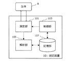
この測定装置10は、図2に示したように、生体Bを測定する測定部101と、制御部103と、解析部105と、記憶部107と、を主に備える。
As shown in FIG. 2, the
[測定部101について]
以下では、まず、図3及び図4を参照しながら、本実施形態に係る測定部101の構成について、具体的に説明する。
本実施形態に係る測定部101は、図3に示したように、光源111と、検出部113と、から構成される。
[About measuring unit 101]
Hereinafter, first, the configuration of the
As shown in FIG. 3, the
○光源について
光源111は、生体内に存在する生体内成分を測定するために用いられ、所定の波長帯域に属する測定光を、生体Bに向かって射出する。この光源111は、測定光の射出面が生体Bと対向するように、所定のフレームFに配設される。光源111は、本実施形態に係る測定装置10で着目する生体内成分を測定するために適した波長の光を射出するものであり、1又は複数の光を射出することができる。
About Light Source The
光源111が射出する測定光の波長は、着目する生体内成分に応じて適宜設定することができる。光源111が940nm、950nmのような波長の光を射出することで、皮下組織に存在する脂肪に関する知見を得ることができる。また、光源111が568nm、580nm、660nm、890nmのような波長の光を射出することで、酸化・還元ヘモグロビン等に関する血中成分やメラニン色素に関する知見を得ることができる。また、光源111が1400nm〜2200nmの波長の光を射出することで、グルコースに関する知見を得ることができる。このような複数の波長の光は、例えば、光源111から時分割で射出される。
The wavelength of the measurement light emitted from the
なお、前述の各種波長は、あくまでも一例であって、本実施形態に係る測定装置10の光源111が射出する光が、上記の例に限定されるわけではない。
The various wavelengths described above are merely examples, and the light emitted from the
このような光源111としては、例えば、発光ダイオード(Light Emitting Diode:LED)や小型のレーザ等を利用可能であり、このような発光デバイスが、光源111として1又は複数個設けられる。
As such a
また、光源111は、後述する制御部103により、上記測定光の射出タイミングや射出される測定光の強度等が制御される。
In addition, the
なお、光源111の配設されるフレームFの形状は特に限定されるわけではないが、光源111と、後述する検出部113との間に図3に示したような壁部を設けることで、このような壁部を、光源111から射出される光が検出部113に入射することを防止する遮光壁として用いることが可能となる。
The shape of the frame F in which the
○検出部について
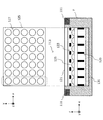
本実施形態に係る測定装置10が備える検出部113は、複数のセンサが所定の配置で規則的に配設されており、光源111から射出され生体Bを透過した測定光を、複数のセンサで検出するものである。換言すれば、本実施形態に係る検出部113は、いわゆるマルチタップセンサにより構成されている。図3では、このような検出部113の一例として、マイクロレンズアレイ(Micro Lens Array:MLA)を利用したセンサを示している。
About the detection unit The
本実施形態に係る測定装置10が備える検出部113は、図3に示したように、例えば、光源111から射出された測定光が属する波長帯域の光を透過可能な透明基板121と、第1遮光体123と、マイクロレンズアレイ125と、第2遮光体129と、センサ131と、を主に備える。
As illustrated in FIG. 3, the
透明基板121は、測定対象物である生体Bの一部が配設される部分である。この透明基板121は、測定処理で利用される波長の光を透過可能な基板を用いて形成される。光源111から射出され、生体Bの内部を透過してきた測定光は、透明基板121を透過すると、第1遮光体123によって指向性が制御される。
The
第1遮光体123は、透明基板121を透過した測定光の指向性を制御する指向性制御板として機能するものであり、後述するマイクロレンズアレイ125において互いに隣り合うマイクロレンズ127の境界部に設けられている。このような第1遮光体123を設けることにより、各マイクロレンズ127に入射する測定光の指向性を制御することが可能となり、より高精度な測定を行うことが可能となる。第1遮光体123を通過した測定光は、マイクロレンズアレイ125へと導光される。
The
マイクロレンズアレイ125は、図3上段に示したように、受光レンズである複数のマイクロレンズ127から構成されており、各マイクロレンズ127は、所定の基板上にx方向及びy方向に沿って格子状に配列されている。各マイクロレンズ127は、マイクロレンズ127に入射した測定光を、後述するセンサ131へと導光する。マイクロレンズアレイ125は、像面湾曲が少なく深さ方向のひずみがないレンズアレイであるため、このようなマイクロレンズアレイ125を用いることで、良好な測定データを得ることができる。なお、マイクロレンズアレイ125を構成する各マイクロレンズ127の被写界深度は、本実施形態に係る測定装置10で着目する皮膚構造を包括するように(例えば、体表から10mmの深さの範囲までがフォーカスされるように)設定される。
As shown in the upper part of FIG. 3, the
なお、本実施形態に係るマイクロレンズアレイ125に配設されるマイクロレンズ127の個数は、図3上段に示した例に限定されるわけではない。本実施形態に係るマイクロレンズアレイ125に配設されるマイクロレンズ127の個数は、撮像したい生体の大きさや、センサ131の大きさに応じて、自由に設定することが可能である。
Note that the number of
マイクロレンズアレイ125に入射した測定光は、マイクロレンズ127により集光されて、後述するセンサ131へと結像されることとなる。
The measurement light incident on the
ここで、マイクロレンズアレイ125におけるセンサ131側に位置する面では、互いに隣り合うマイクロレンズ127の境界部に、第2遮光体129が設けられる。この第2遮光体129により、マイクロレンズアレイ125を透過した測定光の指向性を制御することが可能となり、各マイクロレンズ127に入射した光を、隣接するマイクロレンズ127に入射した光と分離することができる。これにより、本実施形態に係る測定装置10では、センサ131に集光される測定光を選択することが可能となる。
Here, on the surface located on the
センサ131は、図3上段に示したxy平面の各位置における測定光の強度を検出する。このセンサ131は、光検出器(Photo Detector:PD)等により受光した測定光の強度を電気信号に変換して、後述する解析部105へと出力する。このセンサ131としては、フォトダイオードや、CCD(Charge Coupled Devices)型画像センサ、CMOS(Complementary Metal Oxide Semiconductor)型画像センサ、有機ELを受光素子としたセンサ、TFT(Thin Film Transistor)型画像センサや等の2次元エリアセンサを利用することができる。また単純化したモデルとしては、このセンサにx軸方向のラインセンサ等の1次元センサを実装することも可能である。
The
このセンサ131は、後述する制御部103により走査タイミング等が制御され、例えば図3上段における任意の位置の検出強度を解析部105に出力することができる。
The
以上、図3を参照しながら、本実施形態に係る測定部101の構成について、詳細に説明した。
The configuration of the
○測定部により測定されるデータについて
次に、図4を参照しながら、本実施形態に係る測定部101により測定されるデータ(測定データ)について、詳細に説明する。
Regarding Data Measured by Measuring Unit Next, data (measurement data) measured by the measuring
人体は、光を極めて良く散乱させる媒質であるため、光源111から射出され生体Bに入射した測定光は、生体Bの内部を拡散しながら進行して、ある位置に設けられた検出部により検出されることとなる。この際、図4に模式的に示したように、光源111からの位置が離れた位置に存在する検出部ほど、より深い位置まで散乱して体表へと戻ってきた測定光を検出することができる。すなわち、図4において、x軸方向の位置が光源111から離れた位置に存在するセンサ(例えば図4において右側に位置するセンサ)ほど、より深くまで浸透した測定光を検出することができる。
Since the human body is a medium that scatters light very well, the measurement light emitted from the
測定光は、この光が進んだ距離(光学的距離)の長さに応じて、その光路上に存在する各種の生体内成分により特定の波長のエネルギーが吸収され、その強度が減衰していく。そのため、例えば図4に示した模式図において、左から2番目に位置するマイクロレンズアレイにより集光され、センサにより検出された測定光は、図4に示した皮膚層に存在する各種の生体内成分によってエネルギーが吸収されて、その強度が減衰していくこととなる。従って、この位置に対応するセンサによって検出された測定光は、図4に示した皮膚層に関する知見を含む測定データであると言える。同様に、図4に示した模式図において、右から3番目に位置するマイクロレンズアレイにより集光され、センサにより検出された測定光は、図4に示した皮膚層及び脂肪層に存在する各種の生体内成分によってエネルギーが吸収されて、その強度が減衰していくこととなる。従って、この位置に対応するセンサによって検出された測定光は、図4に示した皮膚層及び脂肪層に関する知見を含む測定データであると言える。また、図4に示した模式図において、一番右に位置するマイクロレンズアレイにより集光され、センサにより検出された測定光は、図4に示した皮膚層、脂肪層及び筋肉層に存在する各種の生体内成分によってエネルギーが吸収されて、その強度が減衰していくこととなる。従って、この位置に対応するセンサによって検出された測定光は、図4に示した皮膚層、脂肪層及び筋肉層に関する知見を含む測定データであると言える。 In the measurement light, energy of a specific wavelength is absorbed by various in-vivo components existing on the optical path according to the length of the distance traveled by this light (optical distance), and the intensity thereof is attenuated. . Therefore, for example, in the schematic diagram shown in FIG. 4, the measurement light collected by the microlens array positioned second from the left and detected by the sensor is used in various living bodies existing in the skin layer shown in FIG. 4. Energy is absorbed by the components, and the intensity is attenuated. Therefore, it can be said that the measurement light detected by the sensor corresponding to this position is measurement data including knowledge about the skin layer shown in FIG. Similarly, in the schematic diagram shown in FIG. 4, the measurement light collected by the microlens array located third from the right and detected by the sensor is variously present in the skin layer and the fat layer shown in FIG. 4. The energy is absorbed by the in-vivo components, and the strength is attenuated. Therefore, it can be said that the measurement light detected by the sensor corresponding to this position is measurement data including knowledge about the skin layer and the fat layer shown in FIG. In the schematic diagram shown in FIG. 4, the measurement light collected by the microlens array located on the rightmost and detected by the sensor is present in the skin layer, fat layer and muscle layer shown in FIG. The energy is absorbed by various in-vivo components, and the strength is attenuated. Therefore, it can be said that the measurement light detected by the sensor corresponding to this position is measurement data including knowledge about the skin layer, fat layer and muscle layer shown in FIG.
本実施形態に係る測定装置10では、このような光の特徴に基づき、図4に示した異なるx座標に位置するセンサからの出力(測定データ)を利用して、各センサ位置における光の散乱や減衰の特性をモデル化する。
In the
[制御部103について]
再び図2に戻って、本実施形態に係る測定装置10が備える制御部103について説明する。
制御部103は、例えば、CPU(Central Processing Unit)、ROM(Read Only Memory)、RAM(Random Access Memory)等により実現される。制御部103は、測定部101に設けられた光源111やセンサ131等の駆動制御を行うことにより、測定部101における生体Bの測定処理全般を統括する。より詳細には、制御部103は、所定の同期信号等に基づいて、センサ131の走査タイミングや、情報を取得するセンサ131の選択等といったセンサの駆動制御を行う。また、制御部103は、光源111に対しても、測定光の射出タイミングや強度に関する駆動制御を行う。
[About Control Unit 103]
Returning to FIG. 2 again, the
The
制御部103が以上のような駆動制御を行うことで、測定部101の光源111は、時分割で異なる波長の測定光を射出することが可能となるとともに、センサ131上の任意の位置の測定データを時分割で取得することが可能となる。
When the
制御部103により駆動制御された測定部101によって測定された測定データは、後述する解析部105へと出力されて、測定データの解析処理が実施される。
The measurement data measured by the
ここで、制御部103は、測定部101の制御を行うにあたり、後述する記憶部107に記録されている各種のプログラムやパラメータやデータベース等を参照することが可能である。
Here, the
[解析部105について]
本実施形態に係る測定装置10が備える解析部105は、例えば、CPU、ROM、RAM等により実現される。解析部105は、測定部101により検出された、測定光の検出結果を表した測定データを利用し、光源からの光学的距離に応じて減衰した光量に基づいて、生体内成分の成分量を解析する。
[About Analysis Unit 105]
The
より詳細には、解析部105は、生体の皮下組織をモデル化した上で、「測定部101により測定された測定データが、着目する生体内成分による吸収の線形和として表される」として取り扱うことで、実測された測定データに対する重回帰分析を実施する。解析部105は、このような重回帰分析を実施することで、着目する生体内成分の成分量を算出することができる。
More specifically, the
以下、本実施形態に係る解析部105が実施する解析処理について、図5〜図7を参照しながら、具体的に説明する。
Hereinafter, the analysis processing performed by the
解析部105は、測定された実際のデータと、着目する生体内成分に起因する光吸収量とを関係づけるために、拡張ランベルト・ベールの法則を利用する。本実施形態に係る測定装置10は、生体という光を拡散させる物体(光の散乱体)に着目し、生体内の光の伝播を考慮するものであるため、散乱・拡散の効果を考慮することができない通常のランベルト・ベールの法則を利用することはできない。そのため、本実施形態に係る解析部105は、以下で説明するような拡張ランベルト・ベールの法則を利用して、得られた測定データの解析を実施する。以下、拡張ランベルト・ベールの法則について、図5を参照しながら簡単に説明する。
The
以下の式101は、生体のような光の散乱体の内部を光が伝播する場合に、散乱体の内部に存在する物質によって吸収される光の割合を定式化したものであり、拡張ランベルト・ベールの法則と呼ばれる。

ここで、上記式101において、
λ:着目する光の波長
A(λ):波長λにおける吸光度
I0(λ):散乱体に入射した波長λの光の強度
I(λ):散乱体を透過した波長λの光の検出強度
G(λ):波長λの光の散乱による減衰量
εi(λ):物質iの波長λの光に関する吸光係数であり、物質に固有の値である。
Ci:物質iの濃度
li:波長λの光が物質iを伝播する際の平均光路長
である。
Here, in
λ: wavelength of light of interest A (λ): absorbance at wavelength λ I 0 (λ): intensity of light having wavelength λ incident on scatterer I (λ): detection intensity of light having wavelength λ transmitted through scatterer G (λ): Attenuation amount due to scattering of light of wavelength λ ε i (λ): Absorption coefficient for light of wavelength λ of substance i, which is a value specific to the substance.
C i : concentration of substance i l i : average optical path length when light of wavelength λ propagates through substance i.
ここで、上記拡張ランベルト・ベールの法則を、図5に示したような層構造を有する散乱体に適用することを考える。以下では、層を特定するための添え字を改めてiと記載することとし、層iに含まれる物質の数を添え字jで表すこととする。すると、図5に示したような層構造を有する散乱体における拡張ランベルト・ベールの法則は、下記式102及び式103のように表すことができる。
Here, it is considered that the extended Lambert-Beer law is applied to a scatterer having a layer structure as shown in FIG. In the following, a subscript for specifying a layer is referred to as i, and the number of substances contained in the layer i is expressed as a subscript j. Then, the extended Lambert-Beer law in the scatterer having the layer structure as shown in FIG. 5 can be expressed as the following
ここで、上記式102及び式103において、
λ:着目する光の波長
A(λ):波長λにおける吸光度
I0(λ):散乱体に入射した波長λの光の強度
I(λ):散乱体を透過した波長λの光の検出強度
G(λ):波長λの光の散乱による減衰量
εi(λ):層iの波長λの光に関する吸光係数
Ci:層iに含まれる物質の濃度
li:波長λの光が層iを伝播する際の平均光路長
εij(λ):層iに含まれる物質jの波長λの光に関する吸光係数
Cij:層iに含まれる物質jの濃度
である。
Here, in Equation 102 and
λ: wavelength of light of interest A (λ): absorbance at wavelength λ I 0 (λ): intensity of light having wavelength λ incident on scatterer I (λ): detection intensity of light having wavelength λ transmitted through scatterer G (λ): Attenuation amount due to scattering of light of wavelength λ ε i (λ): Absorption coefficient of light of wavelength λ of layer i C i : Concentration of substance contained in layer i l i : Light of wavelength λ is layer Average optical path length when propagating i ε ij (λ): Absorption coefficient C ij of light of wavelength j of substance j contained in layer i C ij : Concentration of substance j contained in layer i.
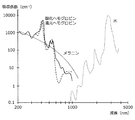
ここで、着目する生体内成分の吸光係数は、例えば図6A〜図6Cのように、予め着目する生体内成分の吸収スペクトルを測定したり、公知のデータベースからデータを取得したりすることで、特定することができる。ここで、図6Aに示したスペクトルは、酸化ヘモグロビン、還元ヘモグロビン、メラニン、水に関する吸収係数εの波長依存性を示したスペクトルであり、図6Bは、グルコースに関する吸収係数εの波長依存性を示したスペクトルであり、図6Cは、脂肪に関する吸収係数εの波長依存性を示したスペクトルである。従って、着目する生体内成分の吸光係数は、これらのデータを利用することによって、既知量として取り扱うことができる。 Here, the extinction coefficient of the in-vivo component of interest is obtained by, for example, measuring the absorption spectrum of the in-vivo component of interest in advance or acquiring data from a known database, as shown in FIGS. 6A to 6C, for example. Can be identified. Here, the spectrum shown in FIG. 6A is a spectrum showing the wavelength dependence of the absorption coefficient ε for oxygenated hemoglobin, reduced hemoglobin, melanin, and water, and FIG. 6B shows the wavelength dependence of the absorption coefficient ε for glucose. FIG. 6C is a spectrum showing the wavelength dependence of the absorption coefficient ε for fat. Therefore, the extinction coefficient of the in vivo component of interest can be handled as a known amount by using these data.
また、上記式102における最左辺は、本実施形態に係る測定部101により測定された、各波長に関する実際の測定データとなる。本実施形態に係る測定部101では、図3に示したマイクロレンズアレイを用いたセンサのように、いわゆるマルチタップセンサを利用しているため、同一の波長λに関して、例えば図4に示したように、x方向位置の異なる複数の測定データを取得することができる。
Further, the leftmost side in the formula 102 is actual measurement data regarding each wavelength measured by the
従って、解析部105は、上記式102及び式103に基づいて、着目する生体内成分の濃度Cijや平均光路長liをフィッティングパラメータとし、センサ位置の異なる複数の実測データに基づいて、波長毎に重回帰分析を行うことができる。これにより、解析部105は、それぞれのセンサ位置に関して、波長毎に皮膚構造モデルの各層に関する推定を行い、着目する生体内成分の成分量を算出したり、層の厚みを算出したりすることができる。
Therefore, the
解析部105は、以上のような重回帰分析により、メラニンや、酸化ヘモグロビン、還元ヘモグロビン等のような血中成分や、水分量等を算出することができる。また、解析部105は、上記成分量に加えて、脂肪層の厚みや、真皮層の厚み等を算出することができる。なお、解析部105が解析可能な生体内成分は、上記例に限定されるわけではなく、生体内成分による光の吸収を測定可能なものであれば、任意の生体内物質に関して解析を行うことが可能である。
The
このように、本実施形態に係る解析部105は、上述のような解析処理を図4に示したような各x座標位置のセンサから取得した実測データを利用して波長毎に行うことで、センサ位置毎の皮膚構造をモデル化することができる。また、解析部105は、センサ位置毎の生体内成分による光の吸収の度合いをプロットすることで、図7に示したような、光強度の減衰カーブを得ることができる。この減衰カーブは、測定光の波長毎に生成することが可能であり、測定光の波長としては、着目する生体内成分の吸収に特徴的な波長が選択される。従って、ある波長の光に関する減衰カーブは、ある生体内成分による吸収の度合いを示した減衰カーブとなる。
As described above, the
例えば、測定光として、波長660nmの光、及び、波長890nmの光の2種類を利用し、これらの光を時分割で生体Bに照射し、時分割で強度を検出することにより、解析部105は、生体内に含まれるメラニン量を算出することができる。解析部105は、これら2つの波長の減衰カーブを生成することで、波長660nmの光におけるメラニンに起因する光の減衰を推定したり、波長890nmの光におけるメラニンに起因する光の減衰を推定したりすることができる。また、波長660nmの光を測定光として用いることで、真皮層の厚みを算出することも可能となる。更に、測定光として、波長940nmの光を用いることで、脂肪に関する減衰カーブを得ることができる。解析部105は、この減衰カーブを利用して、脂肪層の厚みを算出することも可能となる。
For example, as the measurement light, two types of light having a wavelength of 660 nm and light having a wavelength of 890 nm are used, the living body B is irradiated with these lights in a time division, and the intensity is detected in the time division, thereby the
また、解析部105は、パルスオキシメータと同様の原理により、動脈血中に存在する生体内成分による影響と、静脈血中に存在する生体内成分による影響とを分離して、動脈血中に存在する成分の時間的な変動を分離することができる。これにより、時間的な変動の少ない成分に関する解析をより正確に行うことが可能となる。
In addition, the
ここで、測定部101として図3に例示したような各種のマルチタップセンサを利用する場合、図3上段からも明らかなように、あるx座標を有するセンサとしては、y軸方向に沿って存在する複数のセンサ群が該当することとなる。そこで、解析部105は、同一のx座標を有するセンサ群から得られた測定データを積分して、一つのデータとして利用してもよいし、y軸方向のある一つのセンサから得られた測定データをそのまま利用してもよい。
Here, when various multi-tap sensors as illustrated in FIG. 3 are used as the
解析部105は、以上のようにして算出した成分量や生成した減衰カーブを、各波長の光の検出強度の補正に利用することが可能である。かかる成分量や減衰カーブを光の検出強度の補正に利用することで、生体内成分による光吸収の影響を補償することが可能となる。なお、この補正処理については、以下で改めて詳細に説明する。
The
また、解析部105は、例えば、測定対象範囲に存在する特異点のデータを補正したり削除したりすることができる。生体Bには、例えば表面の体毛やアザ、ホクロ、又は、体内の動脈及び静脈の血管など、測定結果に影響を及ぼす要素が存在している部分がある。このような部分では、例えば図3上段に示したy軸方向のセンサ間での測定結果が、不連続に推移すると考えられる。そのため、解析部105は、このような測定データの不連続性に着目して、上記のような部分を特異点として検出することができる。その結果、目視による計測位置の選定や複数回の測定による平均値の取得をしなくても、より正確な測定結果を得ることができる。また、解析部105は、こうして測定される測定量の平坦度によって、現在の測定部位が適切であるかどうかを測定者に音声や表示などによって通知してもよい。
Moreover, the
なお、上記説明では、解析部105が拡張ランベルト・ベールの法則に基づく重回帰分析により生体内成分の成分量等を算出する場合について説明したが、解析部105が解析処理に用いる演算方法は上記例に限定されるわけではなく、例えば、モンテカルロ法を用いたシミュレーション等といった公知の解析方法を利用することも可能である。
In the above description, the case where the
以上、図5〜図7を参照しながら、本実施形態に係る解析部105について、詳細に説明した。
The
[記憶部107について]
再び図2に戻って、本実施形態に係る測定装置10が備える記憶部107について説明する。
記憶部107は、本実施形態に係る測定装置10に設けられたRAMやストレージ装置等により実現される。記憶部107には、解析部105における解析処理に用いられる光吸収スペクトルのデータや、各種のデータベースやルックアップテーブル等が格納されている。また、記憶部107には、本実施形態に係る測定部101により測定された測定データや、本実施形態に係る制御部103や解析部105が実施する処理に用いられる各種のプログラムやパラメータやデータ等が記録されていてもよい。また、記憶部107には、これらのデータ以外にも、測定装置10が、何らかの処理を行う際に保存する必要が生じた様々なパラメータや処理の途中経過等を適宜記憶することが可能である。この記憶部107は、測定部101、制御部103、解析部105等の各処理部が、自由にアクセスし、データを書き込んだり読み出したりすることができる。
[About the storage unit 107]
Returning to FIG. 2 again, the
The
以上、図2〜図7を参照しながら、本実施形態に係る測定装置10の構成について、詳細に説明した。
The configuration of the
以上説明したような本実施形態に係る測定装置10では、光源からの光学的距離に応じて減衰した光量に基づいて、生体内成分の成分量を解析するため、光学モデル(皮膚構造モデル)の変動をもたらしうる生体内成分を正確に測定することが可能となる。
In the measuring
なお、本実施形態に係る制御部103及び解析部105は、本実施形態に係る測定装置10の一部であってもよいし、測定装置10に接続されているコンピュータ等の外部機器に実現されていてもよい。また、測定部101によって生成される測定データがリムーバブル記憶媒体等に格納され、この記憶媒体が測定装置10から取り外されて、解析部105を有する他の装置に接続されることで、測定データが解析されてもよい。
Note that the
また、本実施形態に係る測定装置10を利用して、真皮層の厚み及び脂肪層の厚みに関する解析結果のみを得るのであれば、本実施形態に係る測定部101として、超音波診断装置に用いられる公知の技術を適用することが可能である。
Moreover, if only the analysis result regarding the thickness of the dermis layer and the thickness of the fat layer is obtained using the
以上、本実施形態に係る測定装置10の機能の一例を示した。測定部101以外の上記の各構成要素は、汎用的な部材や回路を用いて構成されていてもよいし、各構成要素の機能に特化したハードウェアにより構成されていてもよい。また、各構成要素の機能を、CPU等が全て行ってもよい。従って、本実施形態を実施する時々の技術レベルに応じて、適宜、利用する構成を変更することが可能である。
Heretofore, an example of the function of the measuring
なお、上述のような本実施形態に係る制御部及び解析部の各機能を実現するためのコンピュータプログラムや、上述のような本実施形態に係る制御部及び解析部を制御するためのコンピュータプログラムを作製し、パーソナルコンピュータ等に実装することが可能である。また、このようなコンピュータプログラムが格納された、コンピュータで読み取り可能な記録媒体も提供することができる。記録媒体は、例えば、磁気ディスク、光ディスク、光磁気ディスク、フラッシュメモリなどである。また、上記のコンピュータプログラムは、記録媒体を用いずに、例えばネットワークを介して配信してもよい。 A computer program for realizing the functions of the control unit and the analysis unit according to the present embodiment as described above, and a computer program for controlling the control unit and the analysis unit according to the present embodiment as described above. It can be manufactured and mounted on a personal computer or the like. In addition, a computer-readable recording medium storing such a computer program can be provided. The recording medium is, for example, a magnetic disk, an optical disk, a magneto-optical disk, a flash memory, or the like. Further, the above computer program may be distributed via a network, for example, without using a recording medium.
<変形例>
[第1変形例]
以上説明した本実施形態に係る測定装置10を用いることで、光学モデル(皮膚構造モデル)の変動をもたらしうる生体内成分を正確に測定することが可能となる。このような測定装置10により得られる生体内成分の成分量や減衰カーブを利用して、測定装置10とは異なる生体物質計測装置により計測された計測データを補正することができる。以下では、図8及び図9を参照しながら、本実施形態に係る測定装置10の変形例について、詳細に説明する。
<Modification>
[First Modification]
By using the
本変形例に係る測定装置30では、図8に示したように、先だって説明した測定装置10を、補正データを測定するための補正データ測定装置10として利用し、別途設けられた生体物質計測装置20により計測された計測データを、補正データ測定装置10により算出された生体内成分の成分量や減衰カーブ等を利用して補正する。
In the
ここで、本変形例に係る補正データ測定装置10は、先だって説明した測定装置10と同様の構成を有し、同様の効果を奏するものであるため、以下では詳細な説明は省略する。
Here, the correction
生体物質計測装置20は、補正データ測定装置10により測定される生体内成分とは異なる生体物質の存在量等を、各種の光学的な手法により計測する装置である。かかる生体物質計測装置20により、グルコース、アルブミン、コレステロール、AGEs(糖化最終産物)等といった、被測定者が健康管理等の観点で注目する体液成分や血中成分が計測される。このような生体物質計測装置20における生体物質の計測手法については、公知の計測技術を適宜利用することが可能である。例えば、生体物質計測装置20は、ラマン分光法、近赤外分光法、紫外線励起蛍光分光法等といった各種の分光学的手法を用いて生体物質を計測してもよいし、ミリ波等の電磁波を生体に照射して、生体から戻ってくる電磁波の量を解析したり、屈折率変化を計測したりすることで生体物質を計測してもよい。
The biological
生体物質計測装置20は、例えば図9に示したように、光源201から所定波長の光を生体Bに向けて射出し、生体Bを透過した透過光を、センサ203により検出することで、着目する生体物質の存在量を計測する。
For example, as shown in FIG. 9, the biological
補正データ測定装置10による生体内成分の測定と、生体物質計測装置20による生体物質の計測とは異なる時間で実施されることが好ましく、光源201からの測定光は、光源101からの測定光とは異なる時間で生体Bに向けて照射されることが好ましい。
The measurement of the in-vivo component by the correction
本変形例に係る測定装置30では、補正データ測定装置10により測定された各種生体内成分の成分量や、生体内における散乱・拡散特性(すなわち減衰カーブ)等を利用して、生体物質計測装置20で計測された計測データの補正(キャリブレーション)を行う。この計測データの補正処理は、補正データ測定装置10が備える解析部105により実施されてもよいし、生体物質計測装置20が備える制御部や解析部(図示せず。)により実施されてもよい。
In the
より詳細には、解析部105又は生体物質計測装置20は、補正データ測定装置10により解析された皮膚構造モデル(生体内物質の成分量や、層構造の厚みや、減衰カーブ等)を利用して、生体物質計測装置20の光源201からの光が、皮膚構造によって吸収・散乱されることで受けた影響(例えば、検出される光の強度の減衰)を補正する。これにより、生体物質計測装置20で実施される多変量解析のモデル変動を補正することが可能となり、生体物質計測装置20で実施される多変量解析の精度劣化を改善し、生体物質を正確に計測することが可能となる。
More specifically, the
このような補正処理(キャリブレーション処理)は、生体物質計測装置20で計測が行われる毎に実施されることが好ましい。補正データ測定装置10により個人差や経時的変化を直接測定することにより、採血などといった侵襲的な手段による生体物質計測装置20のキャリブレーションが不要となり、使用者の利便性を向上させることができる。
Such correction processing (calibration processing) is preferably performed every time measurement is performed by the biological
なお、図8及び図9に示した例では、補正データ測定装置10と生体物質計測装置20とが、別々に実装されている場合について図示しているが、補正データ測定装置10と生体物質計測装置20とは、同一の筺体内に一体に形成されていてもよい。
8 and 9, the correction
[第2変形例]
また、本実施形態に係る測定装置10が、第1変形例における生体物質計測装置20の機能を兼ね備えていてもよい。すなわち、本実施形態に係る測定装置10の有するマルチタップセンサは、先だって説明したような方法により生体内成分に関する測定処理及び解析処理を実施するとともに、生体内成分とは異なる生体物質の計測処理を実施してもよい。
[Second Modification]
Moreover, the measuring
例えば、皮膚に存在するAGEs(糖化最終産物)を紫外線で励起して、AGEsから放射される蛍光を検出することにより、AGEsの定量化を行う場合を考える。この場合に求められるセンサ131の感度は、CCDやCMOS等のシリコンセンサでも十分であるため、蛍光を検出する測定法であっても、本実施形態に係る測定装置10を、生体物質計測装置20として利用することも可能である。この場合、測定装置10に設けられる光源111として、励起光である紫外線を射出可能な紫外線光源と、生体内成分を測定するための光源(例えば、メラニン定量用の568nm、660nm、890nmの光源と、脂肪や水分定量用の940nm、950nm、970nmの光源)を利用する。その上で、制御部103がこれら光源を時間分割で発光させることにより、各成分に関する測定を、互いに干渉しないように実施することができる。
For example, consider the case where AGEs are quantified by exciting AGEs (final glycation end products) present in the skin with ultraviolet light and detecting fluorescence emitted from the AGEs. Since the sensitivity of the
また、RGBカメラのように、紫外線に特化した画素(例えば、B画素の透過特性を紫外線帯域まで拡張したもの)と、生体内成分の測定用画素と、を2次元配列で配置することにより、紫外線光源と生体内成分測定用の光源とを同時発光させて、それぞれの測定を実施することも可能である。 Further, by arranging two-dimensional arrangement of pixels specialized for ultraviolet rays (for example, the transmission characteristics of B pixels extended to the ultraviolet band) and pixels for measuring in-vivo components, as in RGB cameras. It is also possible to carry out the respective measurements by simultaneously emitting light from the ultraviolet light source and the light source for in vivo component measurement.
また、生体物質としてのグルコースをグルコースの光散乱係数に着目して測定する場合、グルコースの光散乱係数は可視光帯域〜1000nmの波長の光を用いることで測定することが可能となる。従って、生体内成分を測定するための測定光と、グルコースを測定するための測定光と、を時分割で発光させることで、1つのセンサ131で生体内成分とグルコースとの測定を行うことが可能となる。
Moreover, when measuring glucose as a biological substance paying attention to the light scattering coefficient of glucose, the light scattering coefficient of glucose can be measured by using light having a wavelength in the visible light band to 1000 nm. Therefore, the measurement light for measuring in-vivo components and the measurement light for measuring glucose are emitted in a time-sharing manner, so that one
なお、上記のいずれの場合においても、生体内成分の測定結果を用いて、生体内成分とは異なる生体物質の計測結果の補正を行うことが可能である。 In any of the above cases, it is possible to correct the measurement result of a biological substance different from the in vivo component using the measurement result of the in vivo component.
また、更に別の変形例として、センサ131として2次元センサを用い、プリズムを利用した分光器を形成することにより、2次元センサの一方の次元で波長帯域を測定し、もう一方の次元で測定位置に伴う変化を測定することも可能となる。従って、皮膚上での1元方向の情報を、体脂肪や真皮層の深さ測定に利用することで、本実施形態に係る機能を実現することも可能となる。
As yet another modification, a two-dimensional sensor is used as the
以上、本実施形態に係る測定装置及び測定方法の変形例について説明した。 In the above, the modification of the measuring apparatus and measuring method which concern on this embodiment was demonstrated.
(ハードウェア構成について)
次に、図10を参照しながら、本開示の実施形態に係る測定装置10のハードウェア構成について、詳細に説明する。図10は、本開示の実施形態に係る測定装置10のハードウェア構成を説明するためのブロック図である。
(About hardware configuration)
Next, the hardware configuration of the
測定装置10は、主に、CPU901と、ROM903と、RAM905と、を備える。また、測定装置10は、更に、ホストバス907、ブリッジ909、外部バス911、インターフェース913、センサ914、入力装置915、出力装置917、ストレージ装置919、ドライブ921、接続ポート923および通信装置925を備える。
The
CPU901は、演算処理装置および制御装置として機能し、ROM903、RAM905、ストレージ装置919、またはリムーバブル記録媒体927に記録された各種プログラムに従って、測定装置10内の動作全般またはその一部を制御する。ROM903は、CPU901が使用するプログラムや演算パラメータ等を記憶する。RAM905は、CPU901が使用するプログラムや、プログラムの実行において適宜変化するパラメータ等を一次記憶する。これらはCPUバス等の内部バスにより構成されるホストバス907により相互に接続されている。
The
ホストバス907は、ブリッジ909を介して、PCI(Peripheral Component Interconnect/Interface)バスなどの外部バス911に接続されている。
The
センサ914は、例えば、ユーザに固有の生体情報、または、かかる生体情報を取得するために用いられる各種情報を検出する検出手段である。このセンサ914として、例えば、CCD(Charge Coupled Device)やCMOS(Complementary Metal Oxide Semiconductor)等の各種の撮像素子を挙げることができる。また、センサ914は、生体部位を撮像するために用いられるレンズ等の光学系や光源等を更に有していてもよい。また、センサ914は、音声等を取得するためのマイクロフォン等であってもよい。なお、センサ914は、上述のもの以外にも、温度計、照度計、湿度計、速度計、加速度計などの様々な測定機器を備えていてもよい。
The
入力装置915は、例えば、マウス、キーボード、タッチパネル、ボタン、スイッチおよびレバーなどユーザが操作する操作手段である。また、入力装置915は、例えば、赤外線やその他の電波を利用したリモートコントロール手段(いわゆる、リモコン)であってもよいし、測定装置10の操作に対応した携帯電話やPDA等の外部接続機器929であってもよい。さらに、入力装置915は、例えば、上記の操作手段を用いてユーザにより入力された情報に基づいて入力信号を生成し、CPU901に出力する入力制御回路などから構成されている。測定装置10のユーザは、この入力装置915を操作することにより、測定装置10に対して各種のデータを入力したり処理動作を指示したりすることができる。
The
出力装置917は、取得した情報をユーザに対して視覚的または聴覚的に通知することが可能な装置で構成される。このような装置として、CRTディスプレイ装置、液晶ディスプレイ装置、プラズマディスプレイ装置、ELディスプレイ装置およびランプなどの表示装置や、スピーカおよびヘッドホンなどの音声出力装置や、プリンタ装置、携帯電話、ファクシミリなどがある。出力装置917は、例えば、測定装置10が行った各種処理により得られた結果を出力する。具体的には、表示装置は、測定装置10が行った各種処理により得られた結果を、テキストまたはイメージで表示する。他方、音声出力装置は、再生された音声データや音響データ等からなるオーディオ信号をアナログ信号に変換して出力する。
The
ストレージ装置919は、測定装置10の記憶部の一例として構成されたデータ格納用の装置である。ストレージ装置919は、例えば、HDD(Hard Disk Drive)等の磁気記憶部デバイス、半導体記憶デバイス、光記憶デバイス、または光磁気記憶デバイス等により構成される。このストレージ装置919は、CPU901が実行するプログラムや各種データ、および外部から取得した各種データなどを格納する。
The
ドライブ921は、記録媒体用リーダライタであり、測定装置10に内蔵、あるいは外付けされる。ドライブ921は、装着されている磁気ディスク、光ディスク、光磁気ディスク、または半導体メモリ等のリムーバブル記録媒体927に記録されている情報を読み出して、RAM905に出力する。また、ドライブ921は、装着されている磁気ディスク、光ディスク、光磁気ディスク、または半導体メモリ等のリムーバブル記録媒体927に記録を書き込むことも可能である。リムーバブル記録媒体927は、例えば、DVDメディア、HD−DVDメディア、Blu−rayメディア等である。また、リムーバブル記録媒体927は、コンパクトフラッシュ(登録商標)(CompactFlash:CF)、フラッシュメモリ、または、SDメモリカード(Secure Digital memory card)等であってもよい。また、リムーバブル記録媒体927は、例えば、非接触型ICチップを搭載したICカード(Integrated Circuit card)または電子機器等であってもよい。
The
接続ポート923は、機器を測定装置10に直接接続するためのポートである。接続ポート923の一例として、USB(Universal Serial Bus)ポート、IEEE1394ポート、SCSI(Small Computer System Interface)ポート等がある。接続ポート923の別の例として、RS−232Cポート、光オーディオ端子、HDMI(High−Definition Multimedia Interface)ポート等がある。この接続ポート923に外部接続機器929を接続することで、測定装置10は、外部接続機器929から直接各種データを取得したり、外部接続機器929に各種データを提供したりする。
The
通信装置925は、例えば、通信網931に接続するための通信デバイス等で構成された通信インターフェースである。通信装置925は、例えば、有線または無線LAN(Local Area Network)、Bluetooth(登録商標)、またはWUSB(Wireless USB)用の通信カード等である。また、通信装置925は、光通信用のルータ、ADSL(Asymmetric Digital Subscriber Line)用のルータ、または、各種通信用のモデム等であってもよい。この通信装置925は、例えば、インターネットや他の通信機器との間で、例えばTCP/IP等の所定のプロトコルに則して信号等を送受信することができる。また、通信装置925に接続される通信網931は、有線または無線によって接続されたネットワーク等により構成され、例えば、インターネット、家庭内LAN、赤外線通信、ラジオ波通信または衛星通信等であってもよい。
The
以上、本開示の実施形態に係る測定装置10の機能を実現可能なハードウェア構成の一例を示した。上記の各構成要素は、汎用的な部材を用いて構成されていてもよいし、各構成要素の機能に特化したハードウェアにより構成されていてもよい。従って、本実施形態を実施する時々の技術レベルに応じて、適宜、利用するハードウェア構成を変更することが可能である。
Heretofore, an example of a hardware configuration capable of realizing the function of the
また、本開示の実施形態に係る生体物質計測装置20のハードウェア構成は、本開示の実施形態に係る測定装置10のハードウェア構成と同様の構成を有しており、同様の効果を奏するものであるため、以下では詳細な説明は省略する。
Further, the hardware configuration of the biological
(まとめ)
以上説明したように、本開示の実施形態に係る測定装置及び測定方法によれば、生体内を光が透過する際に阻害要因となる生体内成分等を正確に測定することが可能となる。これにより、被測定者及び測定部位に由来する光伝搬の散乱、減衰の特性(例えば、メラニン、血液量、脂肪厚、真皮層厚等による光学的な変化)をモデル化することができる。
(Summary)
As described above, according to the measuring apparatus and the measuring method according to the embodiment of the present disclosure, it is possible to accurately measure in vivo components and the like that become an obstruction factor when light passes through the inside of the living body. This makes it possible to model light propagation scattering and attenuation characteristics (for example, optical changes due to melanin, blood volume, fat thickness, dermis layer thickness, etc.) originating from the measurement subject and the measurement site.
また、得られた測定結果を、他の非侵襲光学計測に利用することで、光学モデル(例えば、皮膚構造モデル)の変動を推定することが可能となり、他の非侵襲光学測定において目的とする物質からセンサに到達する光量を適切に補正することができる。その結果、他の非侵襲光学測定において実施される多変量解析の精度劣化を改善できるとともに、採血等の他の手段による測定装置のキャリブレーションが不要となる。 Further, by using the obtained measurement results for other noninvasive optical measurements, it is possible to estimate the variation of the optical model (for example, skin structure model), which is the purpose in other noninvasive optical measurements. The amount of light reaching the sensor from the substance can be corrected appropriately. As a result, the accuracy degradation of multivariate analysis performed in other noninvasive optical measurements can be improved, and calibration of the measuring apparatus by other means such as blood collection becomes unnecessary.
以上、添付図面を参照しながら本開示の好適な実施形態について詳細に説明したが、本開示の技術的範囲はかかる例に限定されない。本開示の技術分野における通常の知識を有する者であれば、特許請求の範囲に記載された技術的思想の範疇内において、各種の変更例または修正例に想到し得ることは明らかであり、これらについても、当然に本開示の技術的範囲に属するものと了解される。 The preferred embodiments of the present disclosure have been described in detail above with reference to the accompanying drawings, but the technical scope of the present disclosure is not limited to such examples. It is obvious that a person having ordinary knowledge in the technical field of the present disclosure can come up with various changes or modifications within the scope of the technical idea described in the claims. Of course, it is understood that it belongs to the technical scope of the present disclosure.
なお、以下のような構成も本開示の技術的範囲に属する。
(1)
生体内に存在する生体内成分を測定するために用いられ、所定の波長帯域に属する測定光を、前記生体に向かって射出する光源と、
複数のセンサが所定の配置で規則的に配設されており、前記光源から射出され前記生体を透過した前記測定光を当該複数のセンサで検出する検出部と、
前記検出部により検出された検出結果を利用し、前記光源からの光学的距離に応じて減衰した光量に基づいて前記生体内成分の成分量を解析する解析部と、
を備える、測定装置。
(2)
前記解析部は、前記生体の皮下組織をモデル化し、前記検出結果を着目する前記生体内成分による吸収の線形和として解析することで、前記生体内成分の成分量を算出する、(1)に記載の測定装置。
(3)
前記検出部は、複数のレンズが格子状に規則的に配設されたマイクロレンズアレイを利用したセンサにより、前記生体を透過した測定光を検出する、(1)又は(2)に記載の測定装置。
(4)
前記光源は、互いに異なる波長を有する複数種類の前記測定光を時分割で前記生体に射出する、(1)〜(3)の何れか1つに記載の測定装置。
(5)
前記解析部は、前記生体内成分として、メラニン、血中成分又は水分の少なくとも何れかの成分量を算出する、(1)〜(4)の何れか1つに記載の測定装置。
(6)
前記解析部は、血液量、脂肪厚又は真皮層厚の少なくとも何れかを更に算出する、(5)に記載の測定装置。
(7)
前記測定装置は、前記生体に含まれる物質を計測する生体物質計測装置を更に備え、
前記生体物質計測装置又は前記解析部は、前記生体物質計測装置における計測結果を、前記生体内成分の成分量を利用して補正する、(1)〜(6)の何れか1つに記載の測定装置。
(8)
前記生体物質計測装置又は前記解析部は、前記生体物質計測装置における計測処理毎に補正処理を実施する、(7)に記載の測定装置。
(9)
前記生体物質計測装置は、前記測定装置と一体に形成されている、(7)又は(8)に記載の測定装置。
(10)
生体内に存在する生体内成分を測定するために用いられ、所定の波長帯域に属する測定光を、前記生体に向かって射出することと、
前記生体を透過した前記測定光を、複数のセンサが所定の配置で規則的に配設された検出ユニットで検出することと、
検出された検出結果を利用し、前記測定光の光源からの光学的距離に応じて減衰した光量に基づいて前記生体内成分の成分量を解析することと、
を含む、測定方法。
(11)
生体内に存在する生体内成分を測定するために用いられ、所定の波長帯域に属する測定光を、前記生体に向かって射出する光源と、複数のセンサが所定の配置で規則的に配設されており、前記光源から射出され前記生体を透過した前記測定光を当該複数のセンサで検出する検出部と、を備える測定機器を制御可能なコンピュータに、
前記光源及び前記検出部を制御する制御機能と、
前記検出部により検出された検出結果を利用し、前記光源からの光学的距離に応じて減衰した光量に基づいて前記生体内成分の成分量を解析する解析機能と、
を実現させるためのプログラム。
(12)
生体内に存在する生体内成分を測定するために用いられ、所定の波長帯域に属する測定光を、前記生体に向かって射出する光源と、複数のセンサが所定の配置で規則的に配設されており、前記光源から射出され前記生体を透過した前記測定光を当該複数のセンサで検出する検出部と、を備える測定機器を制御可能なコンピュータに、
前記光源及び前記検出部を制御する制御機能と、
前記検出部により検出された検出結果を利用し、前記光源からの光学的距離に応じて減衰した光量に基づいて前記生体内成分の成分量を解析する解析機能と、
を実現させるためのプログラムが記録された記録媒体。
(13)
生体に含まれる計測対象物質を計測する生体物質計測装置と、
前記生体内に存在する前記計測対象物質とは異なる生体内成分を測定するために用いられ、所定の波長帯域に属する測定光を、前記生体に向かって射出する光源と、
複数のセンサが所定の配置で規則的に配設されており、前記光源から射出され前記生体を透過した前記測定光を当該複数のセンサで検出する検出部と、
前記検出部により検出された検出結果を利用し、前記光源からの光学的距離に応じて減衰した光量に基づいて前記生体内成分の成分量を解析する解析部と、
を備える、測定装置。
(14)
生体に含まれる計測対象物質を計測する生体物質計測装置と、
前記生体内に存在する前記計測対象物質とは異なる生体内成分を測定するために用いられ、所定の波長帯域に属する測定光を、前記生体に向かって射出する光源と、
複数のセンサが所定の配置で規則的に配設されており、前記光源から射出され前記生体を透過した前記測定光を当該複数のセンサで検出する検出部と、
前記検出部により検出された検出結果を利用し、前記光源からの光学的距離に応じて減衰した光量に基づいて前記生体内成分の成分量を解析する解析部と、
を備え、
前記生体物質計測装置又は前記解析部は、前記生体物質計測装置における計測結果を、前記生体内成分の成分量を利用して補正する、測定装置。
The following configurations also belong to the technical scope of the present disclosure.
(1)
A light source that is used to measure in-vivo components present in the living body and emits measurement light belonging to a predetermined wavelength band toward the living body;
A plurality of sensors are regularly arranged in a predetermined arrangement, and a detection unit that detects the measurement light emitted from the light source and transmitted through the living body with the plurality of sensors,
Using the detection result detected by the detection unit, an analysis unit for analyzing the component amount of the in vivo component based on the amount of light attenuated according to the optical distance from the light source,
A measuring device.
(2)
The analysis unit calculates a component amount of the in vivo component by modeling the subcutaneous tissue of the living body and analyzing the detection result as a linear sum of absorption by the in vivo component focusing on the detection result. The measuring device described.
(3)
The measurement according to (1) or (2), wherein the detection unit detects measurement light transmitted through the living body by a sensor using a microlens array in which a plurality of lenses are regularly arranged in a lattice shape. apparatus.
(4)
The said light source is a measuring apparatus as described in any one of (1)-(3) which inject | emits the multiple types of said measuring light which has a mutually different wavelength to the said biological body by time division.
(5)
The analysis device according to any one of (1) to (4), wherein the analysis unit calculates an amount of at least one of melanin, a blood component, and moisture as the in vivo component.
(6)
The measuring device according to (5), wherein the analysis unit further calculates at least one of blood volume, fat thickness, and dermis layer thickness.
(7)
The measuring device further includes a biological material measuring device that measures a substance contained in the living body,
The biological material measuring device or the analyzing unit corrects a measurement result in the biological material measuring device using a component amount of the in-vivo component, according to any one of (1) to (6). measuring device.
(8)
The measurement apparatus according to (7), wherein the biological material measurement apparatus or the analysis unit performs a correction process for each measurement process in the biological material measurement apparatus.
(9)
The measurement apparatus according to (7) or (8), wherein the biological material measurement apparatus is formed integrally with the measurement apparatus.
(10)
Injecting measurement light belonging to a predetermined wavelength band, which is used to measure in-vivo components existing in the living body, toward the living body;
Detecting the measurement light transmitted through the living body with a detection unit in which a plurality of sensors are regularly arranged in a predetermined arrangement;
Using the detected result detected, analyzing the component amount of the in vivo component based on the amount of light attenuated according to the optical distance from the light source of the measurement light,
Including a measuring method.
(11)
A light source that emits measurement light belonging to a predetermined wavelength band toward the living body and a plurality of sensors that are used to measure in-vivo components existing in the living body are regularly arranged in a predetermined arrangement. And a detection unit that detects the measurement light emitted from the light source and transmitted through the living body with the plurality of sensors, and a computer capable of controlling a measuring device,
A control function for controlling the light source and the detection unit;
Using the detection result detected by the detection unit, an analysis function for analyzing the component amount of the in vivo component based on the amount of light attenuated according to the optical distance from the light source,
A program to realize
(12)
A light source that emits measurement light belonging to a predetermined wavelength band toward the living body and a plurality of sensors that are used to measure in-vivo components existing in the living body are regularly arranged in a predetermined arrangement. And a detection unit that detects the measurement light emitted from the light source and transmitted through the living body with the plurality of sensors, and a computer capable of controlling a measuring device,
A control function for controlling the light source and the detection unit;
Using the detection result detected by the detection unit, an analysis function for analyzing the component amount of the in vivo component based on the amount of light attenuated according to the optical distance from the light source,
A recording medium on which a program for realizing the above is recorded.
(13)
A biological material measuring apparatus for measuring a measurement target substance contained in a living body;
A light source that is used to measure in-vivo components different from the measurement target substance existing in the living body, and emits measurement light belonging to a predetermined wavelength band toward the living body;
A plurality of sensors are regularly arranged in a predetermined arrangement, and a detection unit that detects the measurement light emitted from the light source and transmitted through the living body with the plurality of sensors,
Using the detection result detected by the detection unit, an analysis unit for analyzing the component amount of the in vivo component based on the amount of light attenuated according to the optical distance from the light source,
A measuring device.
(14)
A biological material measuring apparatus for measuring a measurement target substance contained in a living body;
A light source that is used to measure in-vivo components different from the measurement target substance existing in the living body, and emits measurement light belonging to a predetermined wavelength band toward the living body;
A plurality of sensors are regularly arranged in a predetermined arrangement, and a detection unit that detects the measurement light emitted from the light source and transmitted through the living body with the plurality of sensors,
Using the detection result detected by the detection unit, an analysis unit for analyzing the component amount of the in vivo component based on the amount of light attenuated according to the optical distance from the light source,
With
The said biological material measuring device or the said analysis part is a measuring device which correct | amends the measurement result in the said biological material measuring device using the component amount of the said in-vivo component.
10 測定装置(補正データ測定装置)
20 生体物質計測装置
101 測定部
103 制御部
105 解析部
107 記憶部
111 光源
121 透明基板
123 第1遮光体
125 マイクロレンズアレイ
127 マイクロレンズ
129 第2遮光体
131 センサ
201 光源
203 センサ
10 Measuring device (correction data measuring device)
DESCRIPTION OF
Claims (14)
複数のセンサが所定の配置で規則的に配設されており、前記光源から射出され前記生体を透過した前記測定光を当該複数のセンサで検出する検出部と、
前記検出部により検出された検出結果を利用し、前記光源からの光学的距離に応じて減衰した光量に基づいて前記生体内成分の成分量を解析する解析部と、
を備える、測定装置。 A light source that is used to measure in-vivo components present in the living body and emits measurement light belonging to a predetermined wavelength band toward the living body;
A plurality of sensors are regularly arranged in a predetermined arrangement, and a detection unit that detects the measurement light emitted from the light source and transmitted through the living body with the plurality of sensors,
Using the detection result detected by the detection unit, an analysis unit for analyzing the component amount of the in vivo component based on the amount of light attenuated according to the optical distance from the light source,
A measuring device.
前記生体物質計測装置又は前記解析部は、前記生体物質計測装置における計測結果を、前記生体内成分の成分量を利用して補正する、請求項1に記載の測定装置。 The measuring device further includes a biological material measuring device that measures a substance contained in the living body,
The measurement device according to claim 1, wherein the biological material measurement device or the analysis unit corrects a measurement result in the biological material measurement device using a component amount of the in-vivo component.
前記生体を透過した前記測定光を、複数のセンサが所定の配置で規則的に配設された検出ユニットで検出することと、
検出された検出結果を利用し、前記測定光の光源からの光学的距離に応じて減衰した光量に基づいて前記生体内成分の成分量を解析することと、
を含む、測定方法。 Injecting measurement light belonging to a predetermined wavelength band, which is used to measure in-vivo components existing in the living body, toward the living body;
Detecting the measurement light transmitted through the living body with a detection unit in which a plurality of sensors are regularly arranged in a predetermined arrangement;
Using the detected result detected, analyzing the component amount of the in vivo component based on the amount of light attenuated according to the optical distance from the light source of the measurement light,
Including a measuring method.
前記光源及び前記検出部を制御する制御機能と、
前記検出部により検出された検出結果を利用し、前記光源からの光学的距離に応じて減衰した光量に基づいて前記生体内成分の成分量を解析する解析機能と、
を実現させるためのプログラム。 A light source that emits measurement light belonging to a predetermined wavelength band toward the living body and a plurality of sensors that are used to measure in-vivo components existing in the living body are regularly arranged in a predetermined arrangement. And a detection unit that detects the measurement light emitted from the light source and transmitted through the living body with the plurality of sensors, and a computer capable of controlling a measuring device,
A control function for controlling the light source and the detection unit;
Using the detection result detected by the detection unit, an analysis function for analyzing the component amount of the in vivo component based on the amount of light attenuated according to the optical distance from the light source,
A program to realize
前記光源及び前記検出部を制御する制御機能と、
前記検出部により検出された検出結果を利用し、前記光源からの光学的距離に応じて減衰した光量に基づいて前記生体内成分の成分量を解析する解析機能と、
を実現させるためのプログラムが記録された記録媒体。 A light source that emits measurement light belonging to a predetermined wavelength band toward the living body and a plurality of sensors that are used to measure in-vivo components existing in the living body are regularly arranged in a predetermined arrangement. And a detection unit that detects the measurement light emitted from the light source and transmitted through the living body with the plurality of sensors, and a computer capable of controlling a measuring device,
A control function for controlling the light source and the detection unit;
Using the detection result detected by the detection unit, an analysis function for analyzing the component amount of the in vivo component based on the amount of light attenuated according to the optical distance from the light source,
A recording medium on which a program for realizing the above is recorded.
前記生体内に存在する前記計測対象物質とは異なる生体内成分を測定するために用いられ、所定の波長帯域に属する測定光を、前記生体に向かって射出する光源と、
複数のセンサが所定の配置で規則的に配設されており、前記光源から射出され前記生体を透過した前記測定光を当該複数のセンサで検出する検出部と、
前記検出部により検出された検出結果を利用し、前記光源からの光学的距離に応じて減衰した光量に基づいて前記生体内成分の成分量を解析する解析部と、
を備える、測定装置。 A biological material measuring apparatus for measuring a measurement target substance contained in a living body;
A light source that is used to measure in-vivo components different from the measurement target substance existing in the living body, and emits measurement light belonging to a predetermined wavelength band toward the living body;
A plurality of sensors are regularly arranged in a predetermined arrangement, and a detection unit that detects the measurement light emitted from the light source and transmitted through the living body with the plurality of sensors,
Using the detection result detected by the detection unit, an analysis unit for analyzing the component amount of the in vivo component based on the amount of light attenuated according to the optical distance from the light source,
A measuring device.
前記生体内に存在する前記計測対象物質とは異なる生体内成分を測定するために用いられ、所定の波長帯域に属する測定光を、前記生体に向かって射出する光源と、
複数のセンサが所定の配置で規則的に配設されており、前記光源から射出され前記生体を透過した前記測定光を当該複数のセンサで検出する検出部と、
前記検出部により検出された検出結果を利用し、前記光源からの光学的距離に応じて減衰した光量に基づいて前記生体内成分の成分量を解析する解析部と、
を備え、
前記生体物質計測装置又は前記解析部は、前記生体物質計測装置における計測結果を、前記生体内成分の成分量を利用して補正する、測定装置。
A biological material measuring apparatus for measuring a measurement target substance contained in a living body;
A light source that is used to measure in-vivo components different from the measurement target substance existing in the living body, and emits measurement light belonging to a predetermined wavelength band toward the living body;
A plurality of sensors are regularly arranged in a predetermined arrangement, and a detection unit that detects the measurement light emitted from the light source and transmitted through the living body with the plurality of sensors,
Using the detection result detected by the detection unit, an analysis unit for analyzing the component amount of the in vivo component based on the amount of light attenuated according to the optical distance from the light source,
With
The said biological material measuring device or the said analysis part is a measuring device which correct | amends the measurement result in the said biological material measuring device using the component amount of the said in-vivo component.
Priority Applications (4)
| Application Number | Priority Date | Filing Date | Title |
|---|---|---|---|
| JP2011250998A JP2013103094A (en) | 2011-11-16 | 2011-11-16 | Measurement device, measurement method, program, and recording medium |
| CN201280055122.XA CN103917161B (en) | 2011-11-16 | 2012-09-07 | Measurement equipment and measuring method |
| PCT/JP2012/072894 WO2013073270A1 (en) | 2011-11-16 | 2012-09-07 | Measurement device, measurement method, program, and recording medium |
| US14/356,742 US9924874B2 (en) | 2011-11-16 | 2012-09-07 | Measurement device, measurement method, program and recording medium |
Applications Claiming Priority (1)
| Application Number | Priority Date | Filing Date | Title |
|---|---|---|---|
| JP2011250998A JP2013103094A (en) | 2011-11-16 | 2011-11-16 | Measurement device, measurement method, program, and recording medium |
Publications (2)
| Publication Number | Publication Date |
|---|---|
| JP2013103094A true JP2013103094A (en) | 2013-05-30 |
| JP2013103094A5 JP2013103094A5 (en) | 2014-12-18 |
Family
ID=48429344
Family Applications (1)
| Application Number | Title | Priority Date | Filing Date |
|---|---|---|---|
| JP2011250998A Pending JP2013103094A (en) | 2011-11-16 | 2011-11-16 | Measurement device, measurement method, program, and recording medium |
Country Status (4)
| Country | Link |
|---|---|
| US (1) | US9924874B2 (en) |
| JP (1) | JP2013103094A (en) |
| CN (1) | CN103917161B (en) |
| WO (1) | WO2013073270A1 (en) |
Cited By (8)
| Publication number | Priority date | Publication date | Assignee | Title |
|---|---|---|---|---|
| CN104825131A (en) * | 2014-02-11 | 2015-08-12 | 首尔伟傲世有限公司 | Skin condition evaluation apparatus and skin condition evaluation method using the same |
| WO2015151586A1 (en) * | 2014-03-31 | 2015-10-08 | ソニー株式会社 | Measurement device, measurement method, program, and recording medium |
| WO2016047754A1 (en) * | 2014-09-26 | 2016-03-31 | 国立大学法人 香川大学 | Inspection device, attachment configuring said inspection device, portable communication terminal, and program for controlling portable communication terminal |
| JP2016523608A (en) * | 2013-06-06 | 2016-08-12 | プロフサ,インコーポレイテッド | Apparatus and method for detecting optical signal from embedded sensor |
| JP2017003563A (en) * | 2015-06-15 | 2017-01-05 | 株式会社リコー | Optical inspection method and optical inspection device |
| JP2019501688A (en) * | 2015-11-20 | 2019-01-24 | ニルラス・エンジニアリング・アクチエンゲゼルシャフト | Method and apparatus for noninvasive optical measurement of glucose concentration in flowing blood in vivo |
| US10542920B2 (en) | 2014-03-31 | 2020-01-28 | Sony Corporation | Measurement device, measurement method, program, and recording medium |
| US10959619B2 (en) | 2016-03-07 | 2021-03-30 | Samsung Electronics Co., Ltd. | Apparatus and method for acquiring biological information and band for acquiring biological information |
Families Citing this family (11)
| Publication number | Priority date | Publication date | Assignee | Title |
|---|---|---|---|---|
| US10010272B2 (en) | 2010-05-27 | 2018-07-03 | Profusa, Inc. | Tissue-integrating electronic apparatus |
| US10463287B2 (en) | 2010-10-06 | 2019-11-05 | Profusa, Inc. | Tissue-integrating sensors |
| CN113274007A (en) | 2013-03-14 | 2021-08-20 | 普罗菲尤萨股份有限公司 | Method and apparatus for correcting optical signals |
| JP6189716B2 (en) * | 2013-10-31 | 2017-08-30 | シャープ株式会社 | measuring device |
| CN103610467B (en) * | 2013-11-05 | 2016-08-03 | 李鲁亚 | Parallel near infrared light electrical sensor apparatus and animal organ's tissue detection System and method for |
| CN104382567A (en) * | 2014-11-14 | 2015-03-04 | 电子科技大学 | Near infrared spectrum human hemodynamics detection device and motion interference elimination method |
| CN112932416A (en) * | 2015-06-04 | 2021-06-11 | 松下知识产权经营株式会社 | Biological information detection device and biological information detection method |
| EP3558118A4 (en) | 2016-12-21 | 2021-02-24 | Profusa, Inc. | Polymerizable near-ir dyes |
| CN108245742A (en) * | 2018-01-19 | 2018-07-06 | 苏州英诺迈医学科技服务有限公司 | A kind of insulin injection device |
| US20190374134A1 (en) * | 2018-06-11 | 2019-12-12 | Mediatek Inc. | Opto-mechanical design of biosensor for human body signal detection |
| CN112770668A (en) | 2018-07-16 | 2021-05-07 | 布鲁恩医疗创新有限责任公司 | Perfusion and oxygenation measurements |
Citations (31)
| Publication number | Priority date | Publication date | Assignee | Title |
|---|---|---|---|---|
| WO1998023916A1 (en) * | 1996-11-26 | 1998-06-04 | Omron Corporation | Method and apparatus for measuring concentration of light absorbing material in living tissue and thickness of intercalary tissue |
| JPH11501848A (en) * | 1995-03-14 | 1999-02-16 | ネルコー・ピューリタン・ベネット・インコーポレイテッド | Separation layer pulse oximetry |
| JPH1189799A (en) * | 1997-09-19 | 1999-04-06 | Matsushita Electric Ind Co Ltd | Concentration measuring device for specified ingredient |
| JPH11504896A (en) * | 1995-05-10 | 1999-05-11 | ダブリユ・アール・グレイス・アンド・カンパニー・コネテイカツト | Control of expansion in concrete by alkali-silica reaction |
| JPH11287806A (en) * | 1998-04-03 | 1999-10-19 | Sony Corp | Blood-inspecting meter |
| JP2000506048A (en) * | 1996-03-06 | 2000-05-23 | アボット・ラボラトリーズ | Calibration for subsequent monitoring of biological compounds |
| JP2000193585A (en) * | 1998-12-24 | 2000-07-14 | Shimadzu Corp | Optical measuring apparatus |
| JP2002515277A (en) * | 1998-05-18 | 2002-05-28 | アボット・ラボラトリーズ | Non-invasive optical sensor with control of tissue temperature |
| DE10110599A1 (en) * | 2001-03-06 | 2002-09-12 | Roche Diagnostics Gmbh | Method for determining a light transport parameter in a biological matrix |
| JP2003510556A (en) * | 1998-11-23 | 2003-03-18 | アボット・ラボラトリーズ | Non-invasive sensor capable of determining optical parameters of a sample with multiple layers |
| JP2003144421A (en) * | 2001-11-15 | 2003-05-20 | Matsushita Electric Works Ltd | Method and device for determining biocomponent |
| JP2004138454A (en) * | 2002-10-16 | 2004-05-13 | Nikkiso Co Ltd | Method and apparatus for estimating optical scattering characteristics |
| WO2005004712A1 (en) * | 2003-07-09 | 2005-01-20 | Glucon Inc. | Wearable glucometer |
| JP2005169020A (en) * | 2003-12-05 | 2005-06-30 | Tse:Kk | Apparatus for detecting saturation degree of blood oxygen |
| JP2006122579A (en) * | 2004-11-01 | 2006-05-18 | Aime Technology Co Ltd | Noninvasive measurement method for trace component density in scattered medium, and apparatus therefor |
| US20070038041A1 (en) * | 2005-04-25 | 2007-02-15 | Ye Yang | Systems and methods for correcting optical reflectance measurements |
| JP2007295973A (en) * | 2006-04-27 | 2007-11-15 | Nippon Koden Corp | Pulse oxymeter |
| WO2007139192A1 (en) * | 2006-05-31 | 2007-12-06 | National University Corporation Shizuoka University | Optical measuring device, optical measuring method, and storage medium storing optical measurement program |
| JP2008005988A (en) * | 2006-06-28 | 2008-01-17 | Jasco Corp | Blood glucose level analysis method and blood glucose level analyzer |
| JP2008049091A (en) * | 2006-08-28 | 2008-03-06 | Matsushita Electric Works Ltd | Body component concentration measuring method |
| JP2008517664A (en) * | 2004-10-23 | 2008-05-29 | ホーガン,ジョシュ | Correlation of signals obtained simultaneously and non-invasively |
| JP2008168137A (en) * | 2007-01-12 | 2008-07-24 | Tianjin Sunshine Optics Technologies Co Ltd | Optical distance optional type method for atraumatic measurement of human body component, and apparatus therefor |
| JP2008237775A (en) * | 2007-03-28 | 2008-10-09 | Toshiba Corp | Blood component measuring apparatus |
| JP2009090126A (en) * | 2008-12-01 | 2009-04-30 | Sony Corp | Device for acquiring information of blood |
| JP2009125402A (en) * | 2007-11-27 | 2009-06-11 | Spectratech Inc | Biological information measurement device |
| JP2009524474A (en) * | 2005-01-21 | 2009-07-02 | ノニン・メディカル・インコーポレーテッド | Sensor system with memory and method of using the sensor |
| JP2010043942A (en) * | 2008-08-12 | 2010-02-25 | Mitsubishi Chemicals Corp | Operation device of concentration correlation function, method for deriving concentration correlation function, program for operating concentration correlation function, and measuring device of concentration in body fluid of measurement object material |
| WO2010073908A1 (en) * | 2008-12-26 | 2010-07-01 | コニカミノルタセンシング株式会社 | Biological information signal processing apparatus, biological information signal processing method and biological information measuring apparatus |
| JP2010526646A (en) * | 2007-05-11 | 2010-08-05 | シグメッド,インコーポレーティッド | Non-invasive characterization of physiological parameters |
| JP2011152321A (en) * | 2010-01-28 | 2011-08-11 | Sony Corp | Spectrometry device, spectrometry method, and spectrometry program |
| JP2011212116A (en) * | 2010-03-31 | 2011-10-27 | Sony Corp | Fluorescence image acquisition method, fluorescence image acquisition program, and fluorescence image acquisition apparatus |
Family Cites Families (6)
| Publication number | Priority date | Publication date | Assignee | Title |
|---|---|---|---|---|
| JP3577335B2 (en) * | 1993-06-02 | 2004-10-13 | 浜松ホトニクス株式会社 | Scattering absorber measurement method and device |
| US6615061B1 (en) * | 1998-11-23 | 2003-09-02 | Abbott Laboratories | Optical sensor having a selectable sampling distance for determination of analytes |
| KR100827138B1 (en) * | 2006-08-10 | 2008-05-02 | 삼성전자주식회사 | Apparatus for measuring living body information |
| JP4739363B2 (en) * | 2007-05-15 | 2011-08-03 | キヤノン株式会社 | Biological information imaging apparatus, biological information analysis method, and biological information imaging method |
| US20090326347A1 (en) * | 2008-06-30 | 2009-12-31 | Bennett Scharf | Synchronous Light Detection Utilizing CMOS/CCD Sensors For Oximetry Sensing |
| CN101313847B (en) * | 2008-07-01 | 2010-08-25 | 北京师范大学 | Apparatus and method for nondestructive optical constant imaging of dermatosis tissue of human body |
-
2011
- 2011-11-16 JP JP2011250998A patent/JP2013103094A/en active Pending
-
2012
- 2012-09-07 CN CN201280055122.XA patent/CN103917161B/en active Active
- 2012-09-07 US US14/356,742 patent/US9924874B2/en active Active
- 2012-09-07 WO PCT/JP2012/072894 patent/WO2013073270A1/en active Application Filing
Patent Citations (33)
| Publication number | Priority date | Publication date | Assignee | Title |
|---|---|---|---|---|
| JPH11501848A (en) * | 1995-03-14 | 1999-02-16 | ネルコー・ピューリタン・ベネット・インコーポレイテッド | Separation layer pulse oximetry |
| JPH11504896A (en) * | 1995-05-10 | 1999-05-11 | ダブリユ・アール・グレイス・アンド・カンパニー・コネテイカツト | Control of expansion in concrete by alkali-silica reaction |
| JP2000506048A (en) * | 1996-03-06 | 2000-05-23 | アボット・ラボラトリーズ | Calibration for subsequent monitoring of biological compounds |
| WO1998023916A1 (en) * | 1996-11-26 | 1998-06-04 | Omron Corporation | Method and apparatus for measuring concentration of light absorbing material in living tissue and thickness of intercalary tissue |
| JPH1189799A (en) * | 1997-09-19 | 1999-04-06 | Matsushita Electric Ind Co Ltd | Concentration measuring device for specified ingredient |
| JPH11287806A (en) * | 1998-04-03 | 1999-10-19 | Sony Corp | Blood-inspecting meter |
| JP2002515277A (en) * | 1998-05-18 | 2002-05-28 | アボット・ラボラトリーズ | Non-invasive optical sensor with control of tissue temperature |
| JP2003510556A (en) * | 1998-11-23 | 2003-03-18 | アボット・ラボラトリーズ | Non-invasive sensor capable of determining optical parameters of a sample with multiple layers |
| JP2000193585A (en) * | 1998-12-24 | 2000-07-14 | Shimadzu Corp | Optical measuring apparatus |
| DE10110599A1 (en) * | 2001-03-06 | 2002-09-12 | Roche Diagnostics Gmbh | Method for determining a light transport parameter in a biological matrix |
| JP2003144421A (en) * | 2001-11-15 | 2003-05-20 | Matsushita Electric Works Ltd | Method and device for determining biocomponent |
| WO2003041582A1 (en) * | 2001-11-15 | 2003-05-22 | Matsushita Electric Works, Ltd. | Method of measuring biological component concentration and apparatus therefor |
| JP2004138454A (en) * | 2002-10-16 | 2004-05-13 | Nikkiso Co Ltd | Method and apparatus for estimating optical scattering characteristics |
| WO2005004712A1 (en) * | 2003-07-09 | 2005-01-20 | Glucon Inc. | Wearable glucometer |
| US20070085995A1 (en) * | 2003-07-09 | 2007-04-19 | Glucon, Inc. | Wearable glucometer |
| JP2005169020A (en) * | 2003-12-05 | 2005-06-30 | Tse:Kk | Apparatus for detecting saturation degree of blood oxygen |
| JP2008517664A (en) * | 2004-10-23 | 2008-05-29 | ホーガン,ジョシュ | Correlation of signals obtained simultaneously and non-invasively |
| JP2006122579A (en) * | 2004-11-01 | 2006-05-18 | Aime Technology Co Ltd | Noninvasive measurement method for trace component density in scattered medium, and apparatus therefor |
| JP2009524474A (en) * | 2005-01-21 | 2009-07-02 | ノニン・メディカル・インコーポレーテッド | Sensor system with memory and method of using the sensor |
| US20070038041A1 (en) * | 2005-04-25 | 2007-02-15 | Ye Yang | Systems and methods for correcting optical reflectance measurements |
| JP2007295973A (en) * | 2006-04-27 | 2007-11-15 | Nippon Koden Corp | Pulse oxymeter |
| WO2007139192A1 (en) * | 2006-05-31 | 2007-12-06 | National University Corporation Shizuoka University | Optical measuring device, optical measuring method, and storage medium storing optical measurement program |
| JP2008005988A (en) * | 2006-06-28 | 2008-01-17 | Jasco Corp | Blood glucose level analysis method and blood glucose level analyzer |
| JP2008049091A (en) * | 2006-08-28 | 2008-03-06 | Matsushita Electric Works Ltd | Body component concentration measuring method |
| JP2008168137A (en) * | 2007-01-12 | 2008-07-24 | Tianjin Sunshine Optics Technologies Co Ltd | Optical distance optional type method for atraumatic measurement of human body component, and apparatus therefor |
| JP2008237775A (en) * | 2007-03-28 | 2008-10-09 | Toshiba Corp | Blood component measuring apparatus |
| JP2010526646A (en) * | 2007-05-11 | 2010-08-05 | シグメッド,インコーポレーティッド | Non-invasive characterization of physiological parameters |
| JP2009125402A (en) * | 2007-11-27 | 2009-06-11 | Spectratech Inc | Biological information measurement device |
| JP2010043942A (en) * | 2008-08-12 | 2010-02-25 | Mitsubishi Chemicals Corp | Operation device of concentration correlation function, method for deriving concentration correlation function, program for operating concentration correlation function, and measuring device of concentration in body fluid of measurement object material |
| JP2009090126A (en) * | 2008-12-01 | 2009-04-30 | Sony Corp | Device for acquiring information of blood |
| WO2010073908A1 (en) * | 2008-12-26 | 2010-07-01 | コニカミノルタセンシング株式会社 | Biological information signal processing apparatus, biological information signal processing method and biological information measuring apparatus |
| JP2011152321A (en) * | 2010-01-28 | 2011-08-11 | Sony Corp | Spectrometry device, spectrometry method, and spectrometry program |
| JP2011212116A (en) * | 2010-03-31 | 2011-10-27 | Sony Corp | Fluorescence image acquisition method, fluorescence image acquisition program, and fluorescence image acquisition apparatus |
Cited By (15)
| Publication number | Priority date | Publication date | Assignee | Title |
|---|---|---|---|---|
| JP7350526B2 (en) | 2013-06-06 | 2023-09-26 | プロフサ,インコーポレイテッド | Apparatus and method for detecting optical signals from embedded sensors |
| US11504035B2 (en) | 2013-06-06 | 2022-11-22 | Profusa, Inc. | Apparatus and methods for detecting optical signals from implanted sensors |
| JP2019164169A (en) * | 2013-06-06 | 2019-09-26 | プロフサ,インコーポレイテッド | Apparatus and methods for detecting optical signals from implanted sensors |
| JP2016523608A (en) * | 2013-06-06 | 2016-08-12 | プロフサ,インコーポレイテッド | Apparatus and method for detecting optical signal from embedded sensor |
| US10219729B2 (en) | 2013-06-06 | 2019-03-05 | Profusa, Inc. | Apparatus and methods for detecting optical signals from implanted sensors |
| CN104825131A (en) * | 2014-02-11 | 2015-08-12 | 首尔伟傲世有限公司 | Skin condition evaluation apparatus and skin condition evaluation method using the same |
| JPWO2015151586A1 (en) * | 2014-03-31 | 2017-04-13 | ソニー株式会社 | Measuring device, measuring method, program, and recording medium |
| US10542920B2 (en) | 2014-03-31 | 2020-01-28 | Sony Corporation | Measurement device, measurement method, program, and recording medium |
| US10575766B2 (en) | 2014-03-31 | 2020-03-03 | Sony Corporation | Measurement device, measurement method, program, and recording medium |
| WO2015151586A1 (en) * | 2014-03-31 | 2015-10-08 | ソニー株式会社 | Measurement device, measurement method, program, and recording medium |
| JP2016070666A (en) * | 2014-09-26 | 2016-05-09 | 国立大学法人 香川大学 | Inspection device, attachment constituting inspection device, mobile communication terminal, and program for controlling mobile communication terminal |
| WO2016047754A1 (en) * | 2014-09-26 | 2016-03-31 | 国立大学法人 香川大学 | Inspection device, attachment configuring said inspection device, portable communication terminal, and program for controlling portable communication terminal |
| JP2017003563A (en) * | 2015-06-15 | 2017-01-05 | 株式会社リコー | Optical inspection method and optical inspection device |
| JP2019501688A (en) * | 2015-11-20 | 2019-01-24 | ニルラス・エンジニアリング・アクチエンゲゼルシャフト | Method and apparatus for noninvasive optical measurement of glucose concentration in flowing blood in vivo |
| US10959619B2 (en) | 2016-03-07 | 2021-03-30 | Samsung Electronics Co., Ltd. | Apparatus and method for acquiring biological information and band for acquiring biological information |
Also Published As
| Publication number | Publication date |
|---|---|
| US9924874B2 (en) | 2018-03-27 |
| US20140316224A1 (en) | 2014-10-23 |
| CN103917161A (en) | 2014-07-09 |
| WO2013073270A1 (en) | 2013-05-23 |
| CN103917161B (en) | 2016-08-31 |
Similar Documents
| Publication | Publication Date | Title |
|---|---|---|
| WO2013073270A1 (en) | Measurement device, measurement method, program, and recording medium | |
| JP6539877B2 (en) | Measuring device, measuring method, program and recording medium | |
| JP5948836B2 (en) | Measuring device, measuring method, program, and recording medium | |
| Shao et al. | In vivo blood glucose quantification using Raman spectroscopy | |
| US8199322B2 (en) | Apparatus and method for determining analyte concentrations | |
| JP6539876B2 (en) | Measuring device, measuring method, program and recording medium | |
| JP5982364B2 (en) | Apparatus and method for identifying and monitoring components or characteristics of a measurement medium, in particular physiological blood values | |
| US8301216B2 (en) | Method and apparatus for quantification of optical properties of superficial volumes using small source-to-detector separations | |
| Wabnitz et al. | Depth-selective data analysis for time-domain fNIRS: moments vs. time windows | |
| Wang et al. | Dynamic spectrum for noninvasive blood component analysis and its advances | |
| JP5674093B2 (en) | Concentration determination apparatus, concentration determination method, and program | |
| JP5935498B2 (en) | Information processing apparatus, information processing method, program, and information processing system | |
| JP5970785B2 (en) | Biological measuring device, biological measuring method, program, and recording medium | |
| JP5521199B2 (en) | Concentration determination apparatus, concentration determination method, and program | |
| JP5626879B2 (en) | Concentration determination apparatus, concentration determination method, and program | |
| JP5626880B2 (en) | Concentration determination apparatus, concentration determination method, and program | |
| JP6412956B2 (en) | Biological light measurement device, analysis device, and method | |
| JP5818038B2 (en) | Concentration determination apparatus, concentration determination method, and program | |
| Arimoto | Measurement of 2-D SpO2 distribution in skin tissue by multispectral imaging with depth selectivity control |
Legal Events
| Date | Code | Title | Description |
|---|---|---|---|
| A521 | Written amendment |
Free format text: JAPANESE INTERMEDIATE CODE: A523 Effective date: 20141031 |
|
| A621 | Written request for application examination |
Free format text: JAPANESE INTERMEDIATE CODE: A621 Effective date: 20141031 |
|
| A131 | Notification of reasons for refusal |
Free format text: JAPANESE INTERMEDIATE CODE: A131 Effective date: 20151013 |
|
| A521 | Written amendment |
Free format text: JAPANESE INTERMEDIATE CODE: A523 Effective date: 20151202 |
|
| A02 | Decision of refusal |
Free format text: JAPANESE INTERMEDIATE CODE: A02 Effective date: 20160524 |