JP2013007579A - Dispensation method - Google Patents
Dispensation method Download PDFInfo
- Publication number
- JP2013007579A JP2013007579A JP2011138674A JP2011138674A JP2013007579A JP 2013007579 A JP2013007579 A JP 2013007579A JP 2011138674 A JP2011138674 A JP 2011138674A JP 2011138674 A JP2011138674 A JP 2011138674A JP 2013007579 A JP2013007579 A JP 2013007579A
- Authority
- JP
- Japan
- Prior art keywords
- liquid
- tube
- container
- suction
- discharge
- Prior art date
- Legal status (The legal status is an assumption and is not a legal conclusion. Google has not performed a legal analysis and makes no representation as to the accuracy of the status listed.)
- Pending
Links
Images


Classifications
-
- G—PHYSICS
- G01—MEASURING; TESTING
- G01N—INVESTIGATING OR ANALYSING MATERIALS BY DETERMINING THEIR CHEMICAL OR PHYSICAL PROPERTIES
- G01N35/00—Automatic analysis not limited to methods or materials provided for in any single one of groups G01N1/00 - G01N33/00; Handling materials therefor
- G01N35/10—Devices for transferring samples or any liquids to, in, or from, the analysis apparatus, e.g. suction devices, injection devices
- G01N35/1002—Reagent dispensers
-
- G—PHYSICS
- G01—MEASURING; TESTING
- G01N—INVESTIGATING OR ANALYSING MATERIALS BY DETERMINING THEIR CHEMICAL OR PHYSICAL PROPERTIES
- G01N1/00—Sampling; Preparing specimens for investigation
- G01N1/02—Devices for withdrawing samples
- G01N1/10—Devices for withdrawing samples in the liquid or fluent state
- G01N1/14—Suction devices, e.g. pumps; Ejector devices
-
- G—PHYSICS
- G01—MEASURING; TESTING
- G01N—INVESTIGATING OR ANALYSING MATERIALS BY DETERMINING THEIR CHEMICAL OR PHYSICAL PROPERTIES
- G01N1/00—Sampling; Preparing specimens for investigation
- G01N1/28—Preparing specimens for investigation including physical details of (bio-)chemical methods covered elsewhere, e.g. G01N33/50, C12Q
- G01N1/38—Diluting, dispersing or mixing samples
-
- G—PHYSICS
- G01—MEASURING; TESTING
- G01N—INVESTIGATING OR ANALYSING MATERIALS BY DETERMINING THEIR CHEMICAL OR PHYSICAL PROPERTIES
- G01N35/00—Automatic analysis not limited to methods or materials provided for in any single one of groups G01N1/00 - G01N33/00; Handling materials therefor
- G01N35/10—Devices for transferring samples or any liquids to, in, or from, the analysis apparatus, e.g. suction devices, injection devices
- G01N35/1009—Characterised by arrangements for controlling the aspiration or dispense of liquids
- G01N35/1016—Control of the volume dispensed or introduced
-
- B—PERFORMING OPERATIONS; TRANSPORTING
- B01—PHYSICAL OR CHEMICAL PROCESSES OR APPARATUS IN GENERAL
- B01L—CHEMICAL OR PHYSICAL LABORATORY APPARATUS FOR GENERAL USE
- B01L2300/00—Additional constructional details
- B01L2300/08—Geometry, shape and general structure
- B01L2300/0832—Geometry, shape and general structure cylindrical, tube shaped
- B01L2300/0838—Capillaries
-
- B—PERFORMING OPERATIONS; TRANSPORTING
- B01—PHYSICAL OR CHEMICAL PROCESSES OR APPARATUS IN GENERAL
- B01L—CHEMICAL OR PHYSICAL LABORATORY APPARATUS FOR GENERAL USE
- B01L2400/00—Moving or stopping fluids
- B01L2400/04—Moving fluids with specific forces or mechanical means
- B01L2400/0403—Moving fluids with specific forces or mechanical means specific forces
- B01L2400/0457—Moving fluids with specific forces or mechanical means specific forces passive flow or gravitation
-
- B—PERFORMING OPERATIONS; TRANSPORTING
- B01—PHYSICAL OR CHEMICAL PROCESSES OR APPARATUS IN GENERAL
- B01L—CHEMICAL OR PHYSICAL LABORATORY APPARATUS FOR GENERAL USE
- B01L2400/00—Moving or stopping fluids
- B01L2400/04—Moving fluids with specific forces or mechanical means
- B01L2400/0475—Moving fluids with specific forces or mechanical means specific mechanical means and fluid pressure
- B01L2400/0487—Moving fluids with specific forces or mechanical means specific mechanical means and fluid pressure fluid pressure, pneumatics
- B01L2400/049—Moving fluids with specific forces or mechanical means specific mechanical means and fluid pressure fluid pressure, pneumatics vacuum
-
- B—PERFORMING OPERATIONS; TRANSPORTING
- B01—PHYSICAL OR CHEMICAL PROCESSES OR APPARATUS IN GENERAL
- B01L—CHEMICAL OR PHYSICAL LABORATORY APPARATUS FOR GENERAL USE
- B01L3/00—Containers or dishes for laboratory use, e.g. laboratory glassware; Droppers
- B01L3/02—Burettes; Pipettes
- B01L3/0241—Drop counters; Drop formers
-
- B—PERFORMING OPERATIONS; TRANSPORTING
- B01—PHYSICAL OR CHEMICAL PROCESSES OR APPARATUS IN GENERAL
- B01L—CHEMICAL OR PHYSICAL LABORATORY APPARATUS FOR GENERAL USE
- B01L7/00—Heating or cooling apparatus; Heat insulating devices
- B01L7/52—Heating or cooling apparatus; Heat insulating devices with provision for submitting samples to a predetermined sequence of different temperatures, e.g. for treating nucleic acid samples
-
- Y—GENERAL TAGGING OF NEW TECHNOLOGICAL DEVELOPMENTS; GENERAL TAGGING OF CROSS-SECTIONAL TECHNOLOGIES SPANNING OVER SEVERAL SECTIONS OF THE IPC; TECHNICAL SUBJECTS COVERED BY FORMER USPC CROSS-REFERENCE ART COLLECTIONS [XRACs] AND DIGESTS
- Y10—TECHNICAL SUBJECTS COVERED BY FORMER USPC
- Y10T—TECHNICAL SUBJECTS COVERED BY FORMER US CLASSIFICATION
- Y10T436/00—Chemistry: analytical and immunological testing
- Y10T436/11—Automated chemical analysis
- Y10T436/117497—Automated chemical analysis with a continuously flowing sample or carrier stream
- Y10T436/118339—Automated chemical analysis with a continuously flowing sample or carrier stream with formation of a segmented stream
-
- Y—GENERAL TAGGING OF NEW TECHNOLOGICAL DEVELOPMENTS; GENERAL TAGGING OF CROSS-SECTIONAL TECHNOLOGIES SPANNING OVER SEVERAL SECTIONS OF THE IPC; TECHNICAL SUBJECTS COVERED BY FORMER USPC CROSS-REFERENCE ART COLLECTIONS [XRACs] AND DIGESTS
- Y10—TECHNICAL SUBJECTS COVERED BY FORMER USPC
- Y10T—TECHNICAL SUBJECTS COVERED BY FORMER US CLASSIFICATION
- Y10T436/00—Chemistry: analytical and immunological testing
- Y10T436/11—Automated chemical analysis
- Y10T436/119163—Automated chemical analysis with aspirator of claimed structure
-
- Y—GENERAL TAGGING OF NEW TECHNOLOGICAL DEVELOPMENTS; GENERAL TAGGING OF CROSS-SECTIONAL TECHNOLOGIES SPANNING OVER SEVERAL SECTIONS OF THE IPC; TECHNICAL SUBJECTS COVERED BY FORMER USPC CROSS-REFERENCE ART COLLECTIONS [XRACs] AND DIGESTS
- Y10—TECHNICAL SUBJECTS COVERED BY FORMER USPC
- Y10T—TECHNICAL SUBJECTS COVERED BY FORMER US CLASSIFICATION
- Y10T436/00—Chemistry: analytical and immunological testing
- Y10T436/25—Chemistry: analytical and immunological testing including sample preparation
- Y10T436/2575—Volumetric liquid transfer
Landscapes
- Life Sciences & Earth Sciences (AREA)
- General Health & Medical Sciences (AREA)
- Health & Medical Sciences (AREA)
- Chemical & Material Sciences (AREA)
- Analytical Chemistry (AREA)
- Biochemistry (AREA)
- Physics & Mathematics (AREA)
- General Physics & Mathematics (AREA)
- Immunology (AREA)
- Pathology (AREA)
- Hydrology & Water Resources (AREA)
- Automatic Analysis And Handling Materials Therefor (AREA)
- Sampling And Sample Adjustment (AREA)
- Feeding, Discharge, Calcimining, Fusing, And Gas-Generation Devices (AREA)
Abstract
Description
本発明は、液体の分注方法に関する。 The present invention relates to a liquid dispensing method.
生化学の分野において、PCR(Polymerase Chain Reaction:ポリメラーゼ連鎖反応)の技術が確立されている。最近、PCR法における増幅の精度や検出感度は向上してきており、極微量の検体(DNA等)を増幅し、検出・解析することができるようになってきた。 In the field of biochemistry, a technique of PCR (Polymerase Chain Reaction) has been established. Recently, the accuracy and detection sensitivity of amplification in the PCR method have improved, and it has become possible to amplify, detect, and analyze a very small amount of sample (DNA, etc.).
PCRに用いる検体や試薬は、稀少であり高価であることが多いので、PCRの反応液の量(体積)が小さいほど費用および効率の面で好ましい。したがって、PCRの反応液の液量を、できるだけ小さくして取り扱うことができる手法が望まれる。 Samples and reagents used for PCR are rare and expensive in many cases, so the smaller the amount (volume) of the PCR reaction solution, the better in terms of cost and efficiency. Therefore, a technique that can handle the PCR reaction solution as small as possible is desired.
微量の液体を取り扱う方法の例としては、特許文献1に、対象とする液体を、該液体と混和せず相分離をする送液用の液体を用いて、細い管の中で移送する方法が開示されている。また、特許文献2には、遺伝子解析装置として、PCRの反応液を流路内で移動させてPCRを行う装置と、その使用方法が開示されている。 As an example of a method of handling a small amount of liquid, Patent Document 1 discloses a method of transferring a target liquid in a thin tube using a liquid for liquid separation that does not mix with the liquid and performs phase separation. It is disclosed. Patent Document 2 discloses an apparatus for performing PCR by moving a PCR reaction solution in a flow path as a gene analysis apparatus, and a method for using the apparatus.
上記先行技術文献に開示された方法は、対象とする液体を0.5μL(マイクロリットル)より大きい体積で取り扱うものである。そのため、対象となる液体自体は、別途さらに大きい規模で調製されていた。したがって、対象となる液体の調製は、例えば、市販の機器や実験器具を用いて行うことができた。 The method disclosed in the above prior art document deals with a target liquid in a volume larger than 0.5 μL (microliter). Therefore, the target liquid itself was separately prepared on a larger scale. Therefore, preparation of the liquid used as object was able to be performed, for example using a commercially available apparatus and a laboratory instrument.
ところが、特に最近のPCRでは、微量反応の技術の向上や、低コスト化の要望の高まりによって、対象となる液体を、1μL程度の体積で調製することが求められてきている。このような場合には、ナノリットル(nL)のオーダー(1μL未満)の検体や試薬の溶液を正確な体積で、計量、送液等して取り扱う必要があるが、先行文献に開示された方法などで用いられる従来の分注方法では、精密な取り扱いが難しかった。例えば、比較的精密とされる手動のピペットを用いた場合でも、液体の体積が0.2μL未満となると、もはや精度よく計量、送液、分注することは困難であった。 However, in recent PCR in particular, it has been required to prepare a target liquid in a volume of about 1 μL due to an improvement in the technique of a minute reaction and an increase in demand for cost reduction. In such a case, it is necessary to handle a sample or reagent solution in the order of nanoliters (nL) (less than 1 μL) by measuring, feeding, etc. with an accurate volume. In the conventional dispensing method used in the above, precise handling is difficult. For example, even when using a relatively precise manual pipette, it is no longer possible to accurately measure, feed, and dispense when the volume of the liquid is less than 0.2 μL.
また、マイクロリットルあるいはナノリットルのオーダー(100μL未満)の微量の液体は、計量、分注する等の作業において、液体の一部が蒸発する場合があり、液量が変動したり、溶質の濃度が変動したりするという問題もあった。 In addition, a small amount of liquid in the order of microliters or nanoliters (less than 100 μL) may evaporate part of the liquid in operations such as weighing and dispensing, and the amount of liquid may vary or the concentration of solutes. There was also a problem that fluctuated.
本発明は上記課題に鑑みてなされたものであり、その幾つかの態様に係る目的の一つは、微量の液体を精度よく分注する分注方法を提供することにある。 The present invention has been made in view of the above problems, and one of the objects according to some aspects thereof is to provide a dispensing method for dispensing a minute amount of liquid with high accuracy.
本発明は前述の課題の少なくとも一部を解決するためになされたものであり、以下の態様または適用例として実現することができる。 SUMMARY An advantage of some aspects of the invention is to solve at least a part of the problems described above, and the invention can be implemented as the following aspects or application examples.
[適用例1]本発明に係る分注方法の一態様は、第1液体および前記第1液体と混和せず前記第1液体よりも比重の小さい第2液体が収容された第1容器から、管を用いて前記第1液体を第2容器に分注する分注方法であって、前記第2液体を前記管の一端から前記管の内部に吸引する第1吸引工程と、前記第1容器に収容された前記第1液体を前記管の前記一端から前記管の内部に吸引する第2吸引工程と、前記第1容器に収容された前記第2液体を前記管の前記一端から前記管の内部に吸引する第3吸引工程と、前記第3吸引工程で前記管の内部に吸引された前記第2液体を前記第2容器に吐出する第1吐出工程と、前記第2吸引工程で前記管の内部に吸引された前記第1液体を前記第2容器における前記第2液体中に吐出する第2吐出工程と、前記第1吸引工程で前記管の内部に吸引された前記第2液体の少なくとも一部を前記第2容器に吐出する第3吐出工程と、を含む。 [Application Example 1] One aspect of a dispensing method according to the present invention is the following: a first container containing a first liquid and a second liquid that is immiscible with the first liquid and has a specific gravity smaller than that of the first liquid; A dispensing method for dispensing the first liquid into a second container by using a tube, wherein the first suction step of sucking the second liquid from one end of the tube into the tube; and the first container A second suction step for sucking the first liquid contained in the tube from the one end of the tube into the tube; and the second liquid contained in the first container from the one end of the tube to the tube. A third suction step for sucking into the interior; a first discharge step for ejecting the second liquid sucked into the tube in the third suction step into the second container; and the tube in the second suction step. A second discharge for discharging the first liquid sucked into the second liquid into the second liquid in the second container Including a degree, and a third discharge step of discharging at least a portion of the second liquid sucked inside the tube in the first suction step in the second container, the.
本適用例の分注方法によれば、第1液体は、第1容器に収容された状態、並びに吸引工程および吐出工程において、第2液体によって封じられた状態であるので、気相(大気等)に接触しにくい。すなわち、本適用例の分注方法によれば、第1液体は、第1容器から第2容器に分注される際には、第2液体に接する状態で取り扱われるので、大気等に接触しにくい。そのため、第1液体から構成成分が気相に蒸発することや、気相から第1液体へ水などの他の物質が混入することが抑制される。これにより、第1液体の溶媒および溶質の濃度の変動が小さく抑えられ、正確な分注を行うことができる。 According to the dispensing method of this application example, the first liquid is in a state of being accommodated in the first container and sealed in the second liquid in the suction process and the discharge process. ). That is, according to the dispensing method of this application example, when the first liquid is dispensed from the first container to the second container, the first liquid is handled in contact with the second liquid. Hateful. Therefore, it is suppressed that a constituent component evaporates from the first liquid into the gas phase and that other substances such as water are mixed from the gas phase into the first liquid. Thereby, the fluctuation | variation of the density | concentration of the solvent and solute of a 1st liquid is suppressed small, and exact dispensing can be performed.
また、本適用例の分注方法によれば、第2吐出工程で、第1液体が、第2液体中に吐出される。そのため、第2吐出工程において、管内または管の一端付近に第1液体が残存しにくい。したがって精度よく第1液体を第1容器から第2容器へと分注することができる。 Moreover, according to the dispensing method of this application example, the first liquid is discharged into the second liquid in the second discharge step. Therefore, in the second discharge step, the first liquid is unlikely to remain in the tube or near one end of the tube. Therefore, the first liquid can be accurately dispensed from the first container to the second container.
ここで、本明細書において、分注とは、液体をある容器から他の容器へ所定量に分けて移すことを指す。分注との文言は、生化学の分野では当業者に理解されるであろうが、英語では「dispense」に相当する。なお、分注を行う器具は、分注器などと呼称され、英語では「dispenser」と称される。また、本発明に係る分注方法は、生化学の分野に限定されるものではなく、化学、薬学、生物学、工学など広範な分野に適用されうる。また、本明細書において、「分注する」とは、所定の容器から液体を取り出し、他の容器に、当該液体の少なくとも一部を導入することと、所定の容器から液体を取り出し、複数の他の所定の容器に、当該液体を所定量ずつ導入することを含む。 Here, in this specification, dispensing refers to transferring a liquid in a predetermined amount from one container to another. The term “dispensing” will be understood by those skilled in the field of biochemistry, but in English it corresponds to “dispense”. An instrument for performing dispensing is called a dispenser or the like, and is called “dispenser” in English. The dispensing method according to the present invention is not limited to the field of biochemistry, and can be applied to a wide range of fields such as chemistry, pharmacy, biology, and engineering. Further, in this specification, “dispensing” means taking out a liquid from a predetermined container, introducing at least a part of the liquid into another container, taking out the liquid from a predetermined container, Introducing a predetermined amount of the liquid into another predetermined container.
本明細書において、管とは、第1液体が当該管内でプラグ状の形状を維持できる内径を有する筒のことを指す。また、液体がプラグ状の形状を有する状態とは、管の長手方向において、実質的に当該液体のみが占める部分が存在し、他の物質が当該液体によって区画されている状態を指す。ここでの実質的にとは、例えば管の内壁に薄膜状の他の物質(第2液体等)が存在してもよいことを指す。 In this specification, a pipe | tube refers to the cylinder which has an internal diameter in which a 1st liquid can maintain a plug-shaped shape in the said pipe | tube. In addition, the state in which the liquid has a plug-like shape refers to a state in which there is a portion substantially occupied only by the liquid in the longitudinal direction of the tube and other substances are partitioned by the liquid. The term “substantially” here means that, for example, another substance (second liquid or the like) in the form of a thin film may be present on the inner wall of the tube.
[適用例2]本発明に係る分注方法の一態様は、第1液体および前記第1液体と混和せず前記第1液体よりも比重の小さい第2液体が収容された第1容器、並びに、前記第2液体および前記第2液体と混和せず前記第2液体よりも比重の大きい第3液体が収容された第3容器から、管を用いて前記第1液体および前記第3液体を第2容器に分注する分注方法であって、前記第2液体を前記管の一端から前記管の内部に吸引する第1吸引工程と、前記第1容器に収容された前記第1液体を前記管の前記一端から前記管の内部に吸引する第2吸引工程と、前記第1容器に収容された前記第2液体を前記管の前記一端から前記管の内部に吸引する第3吸引工程と、前記第3容器に収容された前記第3液体を前記管の前記一端から前記管の内部に吸引する第4吸引工程と、前記第3容器に収容された前記第2液体を前記管の前記一端から前記管の内部に吸引する第5吸引工程と、前記第5吸引工程で前記管の内部に吸引された前記第2液体を前記第2容器に吐出する第1吐出工程と、前記第4吸引工程で前記管の内部に吸引された前記第3液体を前記第2容器に吐出する第2吐出工程と、前記第3吸引工程で前記管の内部に吸引された前記第2液体の一部を前記第2容器に吐出する第3吐出工程と、前記第3吐出工程で管の内部に残された前記第2液体を前記第2容器に吐出する第4吐出工程と、前記第2吸引工程で前記管の内部に吸引された前記第1液体を前記第2容器に吐出する第5吐出工程と、前記第1吸引工程で前記管の内部に吸引された前記第2液体の少なくとも一部を前記第2容器に吐出する第6吐出工程と、を含む。 Application Example 2 One aspect of the dispensing method according to the present invention is a first container in which a first liquid and a second liquid that is immiscible with the first liquid and has a specific gravity smaller than that of the first liquid, From the third container in which the third liquid that is immiscible with the second liquid and the second liquid and has a specific gravity greater than that of the second liquid is contained, the first liquid and the third liquid are first removed using a tube. A dispensing method for dispensing into two containers, wherein a first suction step of sucking the second liquid from one end of the tube into the tube, and the first liquid stored in the first container are A second suction step for sucking into the tube from the one end of the tube; a third suction step for sucking the second liquid contained in the first container into the tube from the one end of the tube; The third liquid contained in the third container is sucked into the tube from the one end of the tube A fourth suction step, a fifth suction step of sucking the second liquid contained in the third container into the tube from the one end of the tube, and a fifth suction step in which the second liquid is contained in the tube. A first discharge step of discharging the sucked second liquid into the second container, and a second discharge of discharging the third liquid sucked into the tube in the fourth suction step into the second container A third discharge step for discharging a part of the second liquid sucked into the tube in the third suction step into the second container; and a portion left in the tube in the third discharge step. A fourth discharge step for discharging the second liquid into the second container; and a fifth discharge step for discharging the first liquid sucked into the tube in the second suction step into the second container; , At least a portion of the second liquid sucked into the tube in the first suction step Comprising a sixth ejection step of ejecting the vessel, the.
本適用例の分注方法によれば、第1液体および第3液体は、第1容器および第3容器から第2容器に収容された状態、並びに吸引工程および吐出工程において、第2液体によって封じられた状態であるので、気相(大気等)に接触しにくい。すなわち、本適用例の分注方法によれば、第1液体および第3液体は、分注される際には、第2液体に接する状態で取り扱われるので大気等に接触しにくい。そのため、第1液体および第3液体からそれらの構成成分が気相に蒸発することや、気相から第1液体または第3液体へ水などの他の物質が混入することが抑制される。これにより、第1液体および第3液体の濃度の変動が小さく抑えられ、正確な分注を行うことができる。 According to the dispensing method of this application example, the first liquid and the third liquid are sealed by the second liquid in the state where the first container and the third container are accommodated in the second container, and in the suction process and the discharge process. Since it is in a state where it is in a closed state, it is difficult to come into contact with the gas phase (air, etc.). That is, according to the dispensing method of this application example, when the first liquid and the third liquid are dispensed, the first liquid and the third liquid are handled in a state in contact with the second liquid, and thus are difficult to contact the atmosphere or the like. Therefore, it is suppressed that those constituent components evaporate from the first liquid and the third liquid into the gas phase, and that other substances such as water are mixed from the gas phase into the first liquid or the third liquid. Thereby, the fluctuation | variation of the density | concentration of a 1st liquid and a 3rd liquid is suppressed small, and exact dispensing can be performed.
また、本適用例の分注方法によれば、第5吐出工程で、第3液体が第2液体中に吐出され、第2吐出工程で、第1液体が第2液体中に吐出される。そのため、第5吐出工程および第2吐出工程において、管内または管の一端付近に第3液体および第1液体が残存しにくい。したがって精度よく第1液体および第3液体を第2容器へと分注することができる。 Moreover, according to the dispensing method of this application example, the third liquid is discharged into the second liquid in the fifth discharge step, and the first liquid is discharged into the second liquid in the second discharge step. Therefore, in the fifth discharge process and the second discharge process, the third liquid and the first liquid hardly remain in the tube or in the vicinity of one end of the tube. Therefore, the first liquid and the third liquid can be accurately dispensed into the second container.
[適用例3]本発明に係る分注方法の一態様は、第1液体および前記第1液体と混和せず前記第1液体よりも比重の小さい第2液体が収容された第1容器、および、前記第2液体および前記第2液体と混和せず前記第2液体よりも比重の大きい第3液体が収容された第3容器から、一端が開放され他端に液溜が接続された管を用いて、前記第1液体および前記第3液体を第2容器に分注する分注方法であって、前記第2液体を前記管の前記一端から前記管の内部に吸引する第1吸引工程と、前記第1容器に収容された前記第1液体を前記管の前記一端から前記管の内部に吸引する第2吸引工程と、前記第1容器に収容された前記第2液体を前記管の前記一端から前記管の内部に吸引する第3吸引工程と、前記第3容器に収容された前記第3液体を前記管の前記一端から前記管の内部に吸引する第4吸引工程と、前記第3容器に収容された前記第2液体を前記管の前記一端から前記管の内部に吸引する第5吸引工程と、前記管の内部に前記第5吸引工程で吸引された前記第2液体の少なくとも一部が残るように、前記液溜に前記管の内部の各液体を吸引して、前記第2吸引工程で前記管の内部に吸引された前記第1液体、および前記第4吸引工程で前記管の内部に吸引された前記第3液体を、前記液溜内で混合させて第4液体とし、かつ、前記第1吸引工程、前記第3吸引工程、および前記第5吸引工程で吸引された前記第2液体を混合させる混合工程と、前記管の内部に残された前記第2液体を前記第2容器に吐出する第1吐出工程と、前記第4液体を前記第2容器に吐出する第2吐出工程と、前記混合工程で混合された前記第2液体の少なくとも一部を前記第2容器に吐出する第3吐出工程と、を含む。 Application Example 3 In one aspect of the dispensing method according to the present invention, a first container that contains a first liquid and a second liquid that is immiscible with the first liquid and has a specific gravity smaller than that of the first liquid, and A tube having one end opened and a liquid reservoir connected to the other end from a third container containing a second liquid and a third liquid which is immiscible with the second liquid and has a specific gravity greater than that of the second liquid. A dispensing method for dispensing the first liquid and the third liquid into a second container, wherein the second liquid is sucked from the one end of the tube into the tube; A second suction step of sucking the first liquid contained in the first container from the one end of the tube into the tube; and the second liquid housed in the first container in the tube. A third suction step for sucking from one end into the tube; and the third liquid housed in the third container. A fourth suction step for sucking the liquid from the one end of the tube into the tube, and a fifth suction step for sucking the second liquid contained in the third container from the one end of the tube into the tube. Each liquid inside the tube is sucked into the liquid reservoir so that at least a part of the second liquid sucked in the fifth suction step remains inside the tube, and the second suction step. The first liquid sucked into the tube and the third liquid sucked into the tube in the fourth suction step are mixed in the liquid reservoir to form a fourth liquid, and A mixing step of mixing the second liquid sucked in the first suction step, the third suction step, and the fifth suction step; and the second liquid left inside the tube in the second container A first discharge step of discharging the liquid into the second container, and a second discharge of the fourth liquid into the second container. Including out a step, and a third discharge step of discharging at least a portion of the second liquid are mixed in the mixing step to the second container, the.
本適用例の分注方法によれば、第1液体および第3液体を確実に混合することができる。すなわち、本適用例の分注方法によれば、混合工程において第1液体および第3液体の液滴を、液溜中で合一させて第4液体の液滴を形成できるので、第1液体および第3液体を第2容器に吐出した後に第2容器内で両者の液滴を合一させる場合に比べて、より確実に第1液体および第3液体を混合することができる。 According to the dispensing method of this application example, the first liquid and the third liquid can be reliably mixed. That is, according to the dispensing method of this application example, the first liquid and the third liquid droplets can be combined in the liquid reservoir in the mixing step to form the fourth liquid droplets. In addition, the first liquid and the third liquid can be mixed more reliably as compared with the case where the droplets of the two are combined in the second container after the third liquid is discharged to the second container.
また、本適用例の分注方法によれば、第1液体、第3液体および第4液体は、第1容器および第3容器から第2容器に収容された状態、並びに吸引工程、混合工程および吐出工程において、第2液体によって封じられた状態であるので、気相(大気等)に接触しにくい。すなわち、本適用例の分注方法によれば、第1液体、第3液体および第4液体は、分注される際には、第2液体に接する状態で取り扱われるので大気等に接触しにくい。そのため、第1液体、第3液体または第4液体からそれらの構成成分が気相に蒸発することや、気相から第1液体、第3液体または第4液体へ水などの他の物質が混入することが抑制される。これにより、第1液体、第3液体および第4液体の濃度の変動が小さく抑えられ、正確な分注を行うことができる。 Further, according to the dispensing method of this application example, the first liquid, the third liquid, and the fourth liquid are contained in the second container from the first container and the third container, and the suction process, the mixing process, and the In the discharge process, since it is sealed by the second liquid, it is difficult to come into contact with the gas phase (atmosphere or the like). That is, according to the dispensing method of this application example, when the first liquid, the third liquid, and the fourth liquid are dispensed, the first liquid, the third liquid, and the fourth liquid are handled in a state of being in contact with the second liquid, and thus are not easily in contact with the atmosphere or the like. . Therefore, those constituent components evaporate from the first liquid, the third liquid, or the fourth liquid into the gas phase, and other substances such as water are mixed from the gas phase into the first liquid, the third liquid, or the fourth liquid. Is suppressed. Thereby, the fluctuation | variation of the density | concentration of a 1st liquid, a 3rd liquid, and a 4th liquid is suppressed small, and exact dispensing can be performed.
また、本適用例の分注方法によれば、第2吐出工程で、第4液体が第2液体中に吐出される。そのため、第2吐出工程において、管内または管の一端付近に第4液体が残存しにくい。したがって精度よく第4液体を第2容器へと分注することができる。 Moreover, according to the dispensing method of this application example, the fourth liquid is discharged into the second liquid in the second discharge step. For this reason, in the second discharge step, the fourth liquid hardly remains in the tube or in the vicinity of one end of the tube. Therefore, the fourth liquid can be accurately dispensed into the second container.
[適用例4]適用例1ないし適用例3のいずれか一例において、前記第2容器にはあらかじめ前記第2液体が収容されていてもよい。 Application Example 4 In any one of Application Examples 1 to 3, the second container may contain the second liquid in advance.
本適用例の分注方法によれば、各吐出工程において、管の一端を第2液体に接触させやすいので、管内または管の一端付近に第1液体、第3液体または第4液体がさらに残存しにくい。これにより、さらに精度よく第1液体、第3液体または第4液体を第2容器へと分注することができる。 According to the dispensing method of this application example, one end of the tube is easily brought into contact with the second liquid in each discharge step, so that the first liquid, the third liquid, or the fourth liquid further remains in the tube or near one end of the tube. Hard to do. Thereby, the first liquid, the third liquid, or the fourth liquid can be dispensed into the second container with higher accuracy.
[適用例5]本発明に係る分注方法の一態様は、第1液体および前記第1液体と混和せず前記第1液体よりも比重の小さい第2液体が収容された第1容器から、管を用いて前記第1液体を、前記第1液体と混和せず前記第2液体と混和する第3液体が収容された第2容器に管を用いて前記第1液体を分注する分注方法であって、前記第2液体または前記第3液体を前記管の一端から前記管の内部に吸引する第1吸引工程と、前記第1容器に収容された前記第1液体を前記管の前記一端から前記管の内部に吸引する第2吸引工程と、前記第1容器に収容された前記第2液体を前記管の前記一端から前記管の内部に吸引する第3吸引工程と、前記第3吸引工程で前記管の内部に吸引された前記第2液体を前記第2容器に吐出する第1吐出工程と、前記第2吸引工程で前記管の内部に吸引された前記第1液体を前記第2容器に吐出する第2吐出工程と、前記第1吸引工程で前記管の内部に吸引された前記第2液体または前記第3液体の少なくとも一部を前記第2容器に吐出する第11吐出工程と、を含む。 [Application Example 5] One aspect of the dispensing method according to the present invention is as follows: a first container containing a first liquid and a second liquid that is immiscible with the first liquid and has a specific gravity smaller than that of the first liquid; Dispensing the first liquid using a tube into a second container containing a third liquid that is not miscible with the first liquid and miscible with the second liquid. A first suction step of sucking the second liquid or the third liquid from one end of the tube into the tube; and the first liquid accommodated in the first container in the tube. A second suction step for sucking into the tube from one end, a third suction step for sucking the second liquid contained in the first container into the tube from the one end of the tube, and the third A first discharge step of discharging the second liquid sucked into the tube in the suction step into the second container; The second discharge step of discharging the first liquid sucked into the tube in the second suction step into the second container, and the second liquid sucked into the tube in the first suction step Or an eleventh discharge step of discharging at least a part of the third liquid into the second container.
本適用例の分注方法によれば、第1液体は、第1容器から第2容器に収容された状態、並びに吸引工程および吐出工程において、第2液体または第3液体によって封じられた状態であるので、気相(大気等)に接触しにくい。すなわち、本適用例の分注方法によれば、第1液体は、第1容器から第2容器に分注される際には、第2液体または第3液体に接する状態で取り扱われ大気等に接触しにくい。そのため、第1液体から構成成分が気相に蒸発することや、気相から第1液体へ水などの他の物質が混入することが抑制される。これにより、第1液体の溶媒および溶質の濃度の変動が小さく抑えられ、正確な分注を行うことができる。 According to the dispensing method of this application example, the first liquid is contained in the second container from the first container, and is sealed by the second liquid or the third liquid in the suction process and the discharge process. Because there is, it is difficult to contact the gas phase (atmosphere etc.). That is, according to the dispensing method of this application example, when the first liquid is dispensed from the first container to the second container, the first liquid is handled in contact with the second liquid or the third liquid and is released into the atmosphere or the like. Hard to touch. Therefore, it is suppressed that a constituent component evaporates from the first liquid into the gas phase and that other substances such as water are mixed from the gas phase into the first liquid. Thereby, the fluctuation | variation of the density | concentration of the solvent and solute of a 1st liquid is suppressed small, and exact dispensing can be performed.
また、本適用例の分注方法によれば、第2吐出工程で、第1液体が、前記第3液体および前記第2液体の混合液体中に吐出される。そのため、第2吐出工程において、管内または管の一端付近に第1液体が残存しにくい。したがって精度よく第1液体を第1容器から第2容器へと分注することができる。 Moreover, according to the dispensing method of this application example, the first liquid is discharged into the mixed liquid of the third liquid and the second liquid in the second discharge step. Therefore, in the second discharge step, the first liquid is unlikely to remain in the tube or near one end of the tube. Therefore, the first liquid can be accurately dispensed from the first container to the second container.
[適用例6]適用例5において、前記第3液体は、導電性を有してもよい。 Application Example 6 In Application Example 5, the third liquid may have electrical conductivity.
本適用例の分注方法によれば、第1液体および第2液体の少なくとも一方が帯電した場合に、各吐出工程において、管の先端付近で第1液体および第2液体の少なくとも一方が、第3液体との間の静電的な引力または斥力によって、予期せぬ挙動を示すことを抑制することができる。そのため、より確実に第1液体を第1容器から第2容器へと分注することができる。 According to the dispensing method of this application example, when at least one of the first liquid and the second liquid is charged, in each discharge step, at least one of the first liquid and the second liquid is near the tip of the tube. Unexpected behavior can be suppressed by electrostatic attraction or repulsion between the three liquids. Therefore, the first liquid can be more reliably dispensed from the first container to the second container.
[適用例7]適用例1ないし適用例6のいずれか一例において、前記第2液体は、導電性を有してもよい。 Application Example 7 In any one of Application Examples 1 to 6, the second liquid may have conductivity.
本適用例の分注方法によれば、各液体が帯電した場合に、各吐出工程において、管の先端付近で少なくとも第1液体が、第2容器またはその内容物との間の静電的な引力または斥力によって、予期せぬ挙動を示すことを抑制することができる。そのためより確実に第1液体を第2容器へと分注することができる。 According to the dispensing method of this application example, when each liquid is charged, at each discharge step, at least the first liquid is electrostatically charged between the second container or its contents near the tip of the tube. It is possible to suppress unexpected behavior due to attractive force or repulsive force. Therefore, the first liquid can be more reliably dispensed into the second container.
[適用例8]適用例1ないし適用例7のいずれか一例において、前記管は、少なくとも内壁が疎水性を有してもよい。 Application Example 8 In any one of Application Examples 1 to 7, the tube may have at least an inner wall having hydrophobicity.
本適用例の分注方法によれば、管の内壁に水性の液体が付着しにくい。これにより、第1液体、第3液体および第4液体が水溶液である場合に、第2吸引工程とそれ以降の各工程において、管内における第1液体、第3液体および第4液体の移動がより滑らかとなる。また、各吐出工程において、管内に第1液体、第3液体および第4液体がさらに残存しにくい。そのため、より精度よく液体を分注することができる。 According to the dispensing method of this application example, it is difficult for an aqueous liquid to adhere to the inner wall of the tube. As a result, when the first liquid, the third liquid, and the fourth liquid are aqueous solutions, the movement of the first liquid, the third liquid, and the fourth liquid in the tube is further improved in the second suction process and the subsequent processes. Smooth. In each discharge process, the first liquid, the third liquid, and the fourth liquid are less likely to remain in the pipe. Therefore, the liquid can be dispensed with higher accuracy.
以下に本発明のいくつかの実施形態について説明する。以下に説明する実施形態は、本発明の例を説明するものである。本発明は、以下の実施形態になんら限定されるものではなく、本発明の要旨を変更しない範囲において実施される各種の変形例も含む。なお以下の実施形態で説明される構成や工程の全てが本発明の必須構成要件であるとは限らない。 Several embodiments of the present invention will be described below. The embodiments described below illustrate examples of the present invention. The present invention is not limited to the following embodiments at all, and includes various modifications that are carried out within the scope not changing the gist of the present invention. Note that not all of the configurations and processes described in the following embodiments are essential constituent requirements of the present invention.
1.第1実施形態
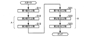
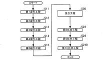
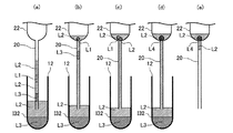
本発明に係る分注方法の第1実施形態を述べる。図1は、本実施形態の分注方法のフローチャートである。図2および図3は、それぞれ本実施形態の分注方法の一部の工程を模式的に示す図である。図2(a)は、本実施形態に係る第1吸引工程を模式的に示し、図2(b)は、本実施形態に係る第2吸引工程を模式的に示し、図2(c)は、本実施形態に係る第3吸引工程を模式的に示し、図2(d)は、本実施形態に係る第3吸引工程を経た後の状態を模式的に示している。図3(a)は、本実施形態に係る第1吐出工程の準備状態を模式的に示し、図3(b)は、本実施形態に係る第1吐出工程を模式的に示し、図3(c)は、本実施形態に係る第2吐出工程を模式的に示し、図3(d)は、本実施形態に係る第3吐出工程を模式的に示している。
1. First Embodiment A first embodiment of a dispensing method according to the present invention will be described. FIG. 1 is a flowchart of the dispensing method of the present embodiment. FIG. 2 and FIG. 3 are diagrams schematically showing some steps of the dispensing method of the present embodiment. 2A schematically shows the first suction step according to the present embodiment, FIG. 2B schematically shows the second suction step according to the present embodiment, and FIG. The 3rd suction process concerning this embodiment is shown typically, and Drawing 2 (d) shows the state after going through the 3rd suction process concerning this embodiment typically. FIG. 3A schematically shows a preparation state of the first discharge process according to this embodiment, FIG. 3B schematically shows the first discharge process according to this embodiment, and FIG. FIG. 3C schematically illustrates the second discharge process according to the present embodiment, and FIG. 3D schematically illustrates the third discharge process according to the present embodiment.
1.1.構成
本実施形態の分注方法は、第1液体L1および第2液体L2が収容された第1容器10から、管20を用いて第1液体L1を第2容器30に分注する分注方法である。
1.1. Configuration The dispensing method of the present embodiment is a dispensing method in which the first liquid L1 is dispensed into the
1.1.1.第1液体
第1液体L1は、後述の第2液体L2と混和しない液体である。また、第1液体L1は、第2液体L2よりも比重が大きい液体である。第1液体L1は、このような性質を有するため、図1に示すように、第1容器10内に第1液体L1および第2液体L2が共存する場合には、第1液体L1と第2液体L2の間に界面I12が形成される。換言すると、第1液体L1と後述の第2液体L2とが共存する場合には液液相分離状態となる。界面I12の重力の作用する方向における下側(第1容器10の底側)に第1液体L1が位置し、界面I12の上側(第1容器10の開口側)に第2液体L2が位置することになる。また、第1液体L1は、表面張力を有し、第1液体L1の体積が小さくなると、第2液体L2中で液滴を形成することができる。なお、本明細書では「上」、「下」との表記は、重力の作用する方向における上下を表すものとする。
1.1.1. 1st liquid The 1st liquid L1 is a liquid which is not miscible with the below-mentioned 2nd liquid L2. The first liquid L1 is a liquid having a specific gravity greater than that of the second liquid L2. Since the first liquid L1 has such properties, as shown in FIG. 1, when the first liquid L1 and the second liquid L2 coexist in the
第1液体L1は、水性、油性のいずれであってもよい。例えば、第1液体L1が水性である場合には、第2液体L2は、油性であることができ、また、その逆であってもよい。第1液体L1は、例えば、PCR(Polymerase Chain Reaction:ポリメラーゼ連鎖反応)の反応液、またはPCRの反応液を調製するための溶液であってもよい。第1液体L1がPCRの反応液である場合には、反応液には増幅の対象とする核酸(標的核酸)および反応に必要な試薬(例えば、DNAポリメラーゼおよびプライマーなど)が含まれる。第1液体L1を用いて調製される溶液がPCRの反応液である場合には、第1溶液L1は、核酸(標的核酸)または反応に必要な試薬のうちの少なくとも一種を含む溶液であることができる。この場合などは、第2容器30に残りの一部の試薬をあらかじめ収容しておいてもよい。また、第1液体L1としては、例えば、大気中の酸素によって酸化されやすい物質や、大気中の水等の分子と反応しやすい物質の溶液であってもよい。
The first liquid L1 may be either aqueous or oily. For example, when the first liquid L1 is aqueous, the second liquid L2 can be oily and vice versa. For example, the first liquid L1 may be a PCR (Polymerase Chain Reaction) reaction solution or a solution for preparing a PCR reaction solution. When the first liquid L1 is a PCR reaction solution, the reaction solution contains a nucleic acid to be amplified (target nucleic acid) and reagents necessary for the reaction (for example, a DNA polymerase and a primer). When the solution prepared using the first liquid L1 is a PCR reaction solution, the first solution L1 is a solution containing at least one of a nucleic acid (target nucleic acid) or a reagent necessary for the reaction. Can do. In this case, the remaining part of the reagent may be stored in the
1.1.2.第2液体
第2液体L2は、第1液体L1と混和しない液体である。また、第2液体L2は、第1液体L1よりも比重が小さい液体である。第2液体L2は、第1液体L1が水性である場合には油性であることができる。例えば、第1液体L1がPCRの反応液、またはPCRの反応液を調製するための溶液である場合には、第2液体L2は、オイルであることができる。このようなオイルとしては、例えば、ジメチルシリコーンオイル等のシリコーン系オイル、パラフィン系オイルおよびミネラルオイル並びにそれらの混合物を挙げることができる。
1.1.2. Second liquid The second liquid L2 is a liquid that is immiscible with the first liquid L1. The second liquid L2 is a liquid having a specific gravity smaller than that of the first liquid L1. The second liquid L2 can be oily when the first liquid L1 is aqueous. For example, when the first liquid L1 is a PCR reaction solution or a solution for preparing a PCR reaction solution, the second liquid L2 can be oil. Examples of such oils include silicone oils such as dimethyl silicone oil, paraffin oils and mineral oils, and mixtures thereof.
1.1.3.管
管20は、両端に開口を有し、内部に該開口間を連通し液体を流通させることができる流路を有する。本明細書では、管20の一方の端を一端といい、他方の端を他端という。また、管20の内径とは、管20の流路の断面における最大径である。管20の形状は任意であるが、例えば、円筒状とすることができる。管20の長さおよび内径は、第1液体L1のプラグを形成できる範囲で任意である。また、管20は、直線状であっても屈曲した形状であってもよい。第1液体L1および第2液体L2などがPCRの反応液等である場合には、管20の内径は、例えば、0.2mm以下が好ましい。管20の内径が0.2mmである場合には、管20内に1mmの長さの液柱を形成すると、当該液柱は、約30ナノリットル(nL)の体積となる。
1.1.3. Tube The
管20は、第1液体L1が当該管20内でプラグ状の形状を維持できる内径を有する。第1液体L1がプラグ状の形状を有する状態とは、管20の長手方向(流路に沿う方向)において、実質的に第1液体L1のみが占める部分が存在する状態をいう。第1液体L1がプラグ状の形状を有する場合は、管20の長手方向において、第1液体L1によって他の物質が区画されている。この場合、例えば管20の内壁に薄膜状の他の物質(第2液体等)が存在してもよい。
The
管20の具体例としては、両端が開口したキャピラリー(細管)が挙げられる。管20は、他端側から流路内が吸引(減圧)されることによって、一端側から液体、気体を流路内に吸引することができる。管20の他端側から流路内を吸引する手段としては、特に限定されず、ポンプ、ピペッター、シリンジなどの機器を例示することができ、作業者が口で吸ってもよい。また、管20は、他端側から流路内に圧力を印加することによって、一端側から液体、気体を吐出させることができる。すなわち、本明細書においては加圧または減圧する器具が取り付けられる管20の端部を他端、液体が吸引または吐出される管20の端部を一端としている。後述する吸引工程において、管20内に、液体のプラグが形成されるため、管20からは、管20に吸引された順番と逆の順番で液体が吐出されることになる(いわゆる先入れ後出し(ファーストインラストアウト))。管20の他端側から流路内に圧力を印加する手段としては、特に限定されず、吸引・加圧機能を備えたポンプ、ピペッター、シリンジなどの機器を例示することができ、作業者が口で息を吹き込んでもよい。なお、1マイクロリットル(μL)以下の体積の第1液体L1を吸引・吐出する場合には、管20内の流速は、1μL/s以下とすることが好ましく、より好ましくは1μL/分以下であり、ポンプ、ピペッターなどの機器は、そのような流速が得られるようなものを用いることが好ましい。
A specific example of the
管20の材質としては、無機材料(例えば耐熱性ガラス(パイレックス(登録商標)))、および有機材料(例えばポリカーボネート、ポリプロピレン、PTFE(ポリテトラフルオロエチレン)等の樹脂)を挙げることができ、これらの複合材料であってもよい。管20がガラス、ポリカーボネート等の可視光を透過する材質で形成されると、管20内に形成された第1液体L1と第2液体L2との間の(相分離)界面I12を外部から目視することができるため好ましい。また、管20の材質としては、撥水性と親油性の両方を備えた材料(例えば、PTFE)が望ましい。管20にこのような材質を用いることにより、第1液体L1が水性であり、かつ、第2液体L2が油性である場合に、管20の表面に第2液体L2が皮膜を形成しやすく、第1液体L1が管20に付着しにくくできる。そのため、複数種の第1液体L1を使用する場合などに、第1液体L1が管20の内壁に付着して生じる第1液体L1間の混合を抑制することができる。
Examples of the material of the
管20は、少なくとも内壁が疎水性を有することが好ましい。管20の少なくとも内壁が疎水性を有すると、分注する液体が水性である場合に、該液体が管20に付着しにくい。また、管20の少なくとも内壁が疎水性を有すると、各実施形態の各工程において、管20内における水性の液体の移動がより滑らかとなり、また、各吐出工程において、管内に水性の液体がさらに残存しにくい。そのため、より精度よく液体を分注することができる。
It is preferable that at least the inner wall of the
管20の内壁を疎水性にする方法としては、管20の材質として上述のPTFEやポリプロピレンを用いることが挙げられ、その他にも管20が疎水性の小さい材質である場合でも、管20の内壁に例えば、プラズマ処理を施したり、疎水性物質のコーティングを施すことによって管20の内壁を疎水性にすることができる。コーティングの例としては、アルキルシラン等で表面処理をした疎水性シリカなどが挙げられる。
As a method for making the inner wall of the
1.1.4.第1容器
第1容器10は、本実施形態の分注方法によって分注される第1液体L1が収容される容器である。本実施形態の分注方法では、第1容器10には、第2液体L2も収容される。第1容器10の形状および容積は、第1液体L1および第2液体L2が収容されたときに、第1容器10内に第1液体L1と第2液体L2との間の界面I12が形成され、第1液体L1が大気に接触しないように配置でき、管20の一端を後述する分注方法に適した位置まで挿入できるかぎり任意である。すなわち、例えば第1容器10の開口および管20の一端の断面形状が円形である場合、第1容器10の開口の直径は管20の一端の外形よりも大きいものが適している。第1容器10は、例えば、試験管、バイアル、生化学の分野で一般に使用される容器などであることができる。
1.1.4. 1st container The
第1容器10の材質としては、無機材料(例えば耐熱性ガラス(パイレックス(登録商標)))、及び有機材料(例えばポリカーボネート、ポリプロピレン等の樹脂)を挙げることができ、これらの複合材料であってもよい。第1容器10がガラス、ポリカーボネート、ポリプロピレン等の可視光を透過する材質で形成されると、第1容器10内に形成された第1液体L1と第2液体L2との間の界面I12を外部から目視することができるため好ましい。
Examples of the material of the
1.1.5.第2容器
第2容器30は、本実施形態の分注方法によって第1液体L1が分注されて収容される。本実施形態の分注方法では、第2容器30には、第2液体L2も収容される。第2容器30の形状は、第1液体L1および第2液体L2が収容されたときに、第2容器30内に第1液体L1と第2液体L2との間の界面I12が形成され、第1液体L1を大気に接触しないように配置できるかぎり任意である。
1.1.5. 2nd container The
本実施形態の分注方法では、第2容器30は、複数準備されてもよい。第2容器30は、例えば、試験管、バイアル、生化学の分野で一般にウェルと称される容器などであることができる。また、第2容器30がウェルである場合には、複数(例えば8×12=96個)のウェルが一つの部材に形成された板を使用することができる。
In the dispensing method of the present embodiment, a plurality of
第2容器30の材質としては、無機材料(例えば耐熱性ガラス(パイレックス(登録商標)))、及び有機材料(例えばポリカーボネート、ポリプロピレン等の樹脂)を挙げることができ、これらの複合材料であってもよい。
Examples of the material of the
また、第2容器30の外部から、その内部を観察するような用途(例えば、リアルタイムPCRなど)に第2容器30を用いる場合には、必要に応じて、材質を透明なものとすることができる。なお、ここでの「透明」の程度は第2容器30の使用目的に適する程度であればよい。例えば、視覚的な観察であれば内部が視認できる程度であればよい。リアルタイムPCRなどにおける蛍光測定であれば第2容器30外部から反応液の蛍光が光学的に測定できる程度であればよい。第2容器30の開口から蛍光測定を行う場合には、第2容器30の材質に、カーボンブラック、グラファイト、チタンブラック、アニリンブラック、若しくは、Ru、Mn、Ni、Cr、Fe、Co又はCuの酸化物、Si、Ti、Ta、Zr又はCrの炭化物などの黒色物質等を配合することにより、樹脂等の有する自発蛍光を抑制することができ、PCRの精度を高めることができる。またなお、第2容器30を、PCRの反応容器として使用する場合には、第2容器30の材質は、核酸やタンパク質の吸着が少なく、ポリメラーゼ等の酵素反応を阻害しない材質であることが好ましい。
In addition, when the
1.2.分注方法
本実施形態の分注方法は、第1吸引工程と、第2吸引工程と、第3吸引工程と、第1吐出工程と、第2吐出工程と、第3吐出工程とを含む。
1.2. Dispensing Method The dispensing method of the present embodiment includes a first suction process, a second suction process, a third suction process, a first discharge process, a second discharge process, and a third discharge process.
1.2.1.第1吸引工程
第1吸引工程(ステップS11)では、第2液体L2を管20の一端側から管20内に吸引する。第1吸引工程で吸引される第2液体L2は、第1容器10内に収容された第2液体L2であっても、他の容器に収容された第2液体L2であってもよい。第1吸引工程で吸引される第2液体L2の体積は特に限定されないが、第2吸引工程で吸引される第1液体L1が管20内の気体の影響を受けない程度の体積であることが好ましい。
1.2.1. First Suction Step In the first suction step (step S11), the second liquid L2 is sucked into the
第1吸引工程によって、管20の内壁の第2液体L2が接触した領域が第2液体L2に覆われる。これにより、第2吸引工程で吸引される第1液体L1が管20の内壁に付着しにくくし、および第2吸引工程で吸引される第1液体L1が管20内で移動しやすくすることができる。第1吸引工程を行うことにより、第2吸引工程で吸引される第1液体L1が管20内の気体と接触しにくくすることができる。
By the first suction step, the region of the inner wall of the
図2(a)は、第1吸引工程において、第1容器10内に収容された第2液体L2を管20の一端側から吸引した様子を模式的に表している。第1吸引工程を経ると、管20の一端側に、第2液体L2の液柱が形成される。
FIG. 2A schematically shows a state in which the second liquid L2 accommodated in the
1.2.2.第2吸引工程
第2吸引工程(ステップS12)は、第1吸引工程(ステップS11)の後で行われる。第2吸引工程と第1吸引工程との間には、例えば、第1吸引工程で第1容器10以外の容器から第2液体L2を吸引した場合に、管20の一端を第1容器10内に移動させるなどの、他の工程が行われてもよい。
1.2.2. Second Suction Process The second suction process (Step S12) is performed after the first suction process (Step S11). Between the second suction process and the first suction process, for example, when the second liquid L2 is sucked from a container other than the
第2吸引工程では、第1容器10において管20の一端が第1液体L1と第2液体L2との界面I12より下の位置で、第1液体L1を管20の一端側から管20内に吸引する。第2吸引工程で界面I12より下の位置に配置される一端は、第1吸引工程で第2液体L2を吸引した一端である。
In the second suction step, one end of the
第1吸引工程で、第1容器10内の第2液体L2を吸引した場合には、管20の一端を界面I12よりも下に移動させることにより、第2吸引工程を行うことができる。第2吸引工程で吸引される第1液体L1の体積は特に限定されない。
When the second liquid L2 in the
図2(b)は、第2吸引工程において、第1容器10内に収容された第1液体L1を管20の一端側から吸引した様子を模式的に表している。第2吸引工程を経ると、管20の一端側に、第2液体L2の液柱の下に第1液体L1の液柱が形成される。
FIG. 2B schematically shows a state in which the first liquid L1 accommodated in the
1.2.3.第3吸引工程
第3吸引工程(ステップS13)は、第2吸引工程(ステップS12)に連続して行われる。第3吸引工程では、第1容器10において管20の一端が界面I12より上の位置で、第2液体L2を管20の一端側から管20内に吸引する。第3吸引工程で界面I12より上の位置に配置される一端は、第2吸引工程で第1液体L1を吸引した一端である。本明細書において、「A工程がB工程に連続して行われる」との表現は、A工程がB工程を行った容器において行われることを表す。また、「A工程がB工程の後で行われる」との表現は、A工程がB工程に連続して行われる場合と、A工程とB工程の間に他の工程が行われる場合とを含む。
1.2.3. Third Suction Process The third suction process (Step S13) is performed continuously with the second suction process (Step S12). In the third suction step, the second liquid L2 is sucked into the
第3吸引工程で吸引される第2液体L2の体積は特に限定されない。第1吐出工程で、第2容器30にあらかじめ第2液体L2が収容されていない場合には、第3吸引工程で吸引された第2液体L2の体積は、当該第2液体L2が第1吐出工程で吐出された際に管20の一端の開口を浸す程度よりも大きいことが好ましい。
The volume of the second liquid L2 sucked in the third suction step is not particularly limited. When the second liquid L2 is not previously stored in the
図2(c)は、第3吸引工程において、第1容器10内に収容された第2液体L2を管20の一端側から吸引した様子を模式的に表している。第3吸引工程を経ると、管20の内部において、第1液体L1の液柱が2つの第2液体L2の液柱に挟まれた状態となる。図2(d)は、第3吸引工程を経た後の管20の状態を示している。図2(d)に示すように、第3吸引工程を経た後の管20では、一端側から第2液体L2、第1液体L1、第2液体L2の順に液柱が形成されるので、第1液体L1を空気にほとんど触れさせない状態で管20を移動させることができる。
FIG. 2C schematically shows a state in which the second liquid L2 accommodated in the
1.2.4.第1吐出工程
第1吐出工程(ステップS21)は、第3吸引工程(ステップS13)の後で行われる。第3吸引工程と第1吐出工程との間には、少なくとも第1容器10から管20を第2容器30に移動させる工程が行われる。第3吸引工程と第1吐出工程との間には、他の工程が行われてもよい。
1.2.4. First Discharge Process The first discharge process (Step S21) is performed after the third suction process (Step S13). Between the third suction step and the first discharge step, at least a step of moving the
第1吐出工程では、第3吸引工程(ステップS13)で管20内に吸引された第2液体L2を、管20の一端側から第2容器30に吐出する。第1吐出工程で第2液体L2が吐出される一端は、第3吸引工程で第2液体L2を吸引した一端である。
In the first discharge step, the second liquid L2 sucked into the
第1吐出工程では、第2容器30に第2液体L2が吐出されるが、吐出された第2液体L2に管20の一端の開口が浸されるように行われる。第1吐出工程において、管20の一端の開口が浸されることにより、第2吐出工程で吐出される第1液体L1を大気に接触させないようにすることができる。また、第2液体L2に管20の一端の開口が浸されることにより、第2吐出工程で吐出される第1液体L1を管20から吐出させやすくすることができる。
In the first discharge step, the second liquid L2 is discharged into the
第1吐出工程で吐出される第2液体L2を収容する第2容器30には、あらかじめ第2液体L2が収容されていてもよい。このようにすれば、第1吐出工程の前後で第2液体L2に管20の一端の開口を浸しやすく、第2吐出工程で吐出される第1液体L1をさらに大気に接触させにくくすることができる。また、第2容器30にあらかじめ第2液体L2が収容されていると、第2吐出工程で吐出される第1液体L1を管20からさらに吐出させやすくすることができる。
The second liquid L2 may be stored in advance in the
図3(a)は、第3吸引工程を経た後の管20が、第2容器30内に配置された状態を示している。図3(b)は、第1吐出工程が終了した状態を示しており、管20内に第1液体L1および第2液体L2の液柱が残存している状態を示している。
FIG. 3A shows a state in which the
1.2.5.第2吐出工程
第2吐出工程(ステップS22)は、第1吐出工程(ステップS21)に連続して行われる。第2吐出工程では、第2吸引工程(ステップS12)で管20内に吸引された第1液体L1を、管20の一端側から第2容器30に吐出する。第2吐出工程で第1液体L1が吐出される一端は、第2吸引工程で第1液体L1を吸引した一端である。
1.2.5. Second Discharge Process The second discharge process (Step S22) is performed continuously with the first discharge process (Step S21). In the second discharge step, the first liquid L1 sucked into the
第2吐出工程は、第2液体L2に管20の一端の開口が浸された状態で行われる。これにより、第2吐出工程で吐出される第1液体L1を大気に接触させないようにすることができる。また、第2液体L2に管20の一端の開口が浸されることにより、第2吐出工程で吐出される第1液体L1を管20から吐出させやすくなっている。
The second discharge step is performed in a state where the opening at one end of the
図3(c)は、第2吐出工程が終了した状態を示しており、管20内に第2液体L2の液柱が残存し、第1液体L1が管20から出て、管20の一端に接触している状態を示している。第2吐出工程は、第2容器30中の第2液体L2に管20の一端の開口が浸されて行われるため、第1液体L1が大気に接触することがない。
FIG. 3C shows a state in which the second discharge process has been completed. The liquid column of the second liquid L2 remains in the
1.2.6.第3吐出工程
第3吐出工程(ステップS23)は、第2吐出工程(ステップS22)に連続して行われる。第3吐出工程では、第1吸引工程(ステップS11)で管20内に吸引された第2液体L2の少なくとも一部を、管20の一端側から第2容器30に吐出する。第3吐出工程で第2液体L2が吐出される一端は、第1吸引工程で第2液体L2を吸引した一端である。
1.2.6. Third Discharge Process The third discharge process (Step S23) is performed continuously with the second discharge process (Step S22). In the third discharge step, at least a part of the second liquid L2 sucked into the
第3吐出工程は、第2液体L2に管20の一端の開口が浸された状態で行われる。これにより、第3吐出工程で吐出される第2液体L2が、第2容器30中の第2液体L2と合一し、第2吐出工程で吐出された第1液体L1を管20から離脱させることができる。
The third discharge step is performed in a state where the opening at one end of the
第3吐出工程で吐出される第2液体L2は、第1吸引工程で管20内に吸引された第2液体L2の一部であっても全部であってもよい。
The second liquid L2 discharged in the third discharge process may be part or all of the second liquid L2 sucked into the
図3(d)は、第3吐出工程が終了し、第3吐出工程で第2液体L2の一部が吐出された状態を示しており、管20内に第2液体L2の液柱が残存し、第1液体L1が管20から離脱した状態を示している。第3吐出工程では、第2容器30中の第2液体L2に管20の一端の開口が浸されて行われるため、第1液体L1が大気に接触しにくい。また、第3吐出工程は、第2容器30中の第2液体L2に管20の一端の開口が浸されて行われるため、第3吐出工程によって、図示のように、管20内の第2液体L2の液柱と第2容器30内の第2液体L2とを連続させることができる。そのため、第1液体L1を管20の一端の開口から容易に離脱させることができる。なお、図3(d)では、離脱した第1液体L1が液滴を形成している例を示している。
FIG. 3D shows a state in which the third discharge process is completed and a part of the second liquid L2 is discharged in the third discharge process, and the liquid column of the second liquid L2 remains in the
1.2.7.変形実施形態
上記第1実施形態では、1つの第1容器10から、1つの第2容器30へ第1液体L1を分注する分注方法を説明した。しかし、第1実施形態の分注方法は、1つの第1容器10から、複数の第2容器30へ第1液体L1を分注する変形実施が可能である。以下では、1つの第1容器10から、2つの第2容器30へ第1液体L1を分注する方法を説明する。
1.2.7. Modified Embodiment In the first embodiment, the dispensing method for dispensing the first liquid L1 from one
本変形実施形態の分注方法は、第1吸引工程と、第2吸引工程と、第3吸引工程と、第1吐出工程と、第2吐出工程と、第3吐出工程とを含む。各工程は、上記第1実施形態で述べたと同様であるため、詳細な説明を省略する。 The dispensing method of the present modified embodiment includes a first suction process, a second suction process, a third suction process, a first discharge process, a second discharge process, and a third discharge process. Since each process is the same as that described in the first embodiment, detailed description thereof is omitted.
本変形実施形態の分注方法では、図1に示したフローチャートのAで示す工程(第2吸引工程および第3吸引工程)が複数回行われ、最後の第3吸引工程の後、Bで示す工程(第1吐出工程、第2吐出工程および第3吐出工程)が複数回行われる。 In the dispensing method of the present modified embodiment, the step (second suction step and third suction step) indicated by A in the flowchart shown in FIG. 1 is performed a plurality of times, and indicated by B after the last third suction step. A process (a 1st discharge process, a 2nd discharge process, and a 3rd discharge process) is performed in multiple times.
上記第1実施形態において、第3吸引工程が終了した後、再度、第2吸引工程および第3吸引工程を行うと、2回目の第3吸引工程が終了したときに、管20内には、一端側から第2液体L2、第1液体L1、第2液体L2、第1液体L1、第2液体L2の順に液柱が形成され、この状態で管20を移動させることができる。
In the first embodiment, when the second suction step and the third suction step are performed again after the third suction step is finished, when the second third suction step is finished, A liquid column is formed in the order of the second liquid L2, the first liquid L1, the second liquid L2, the first liquid L1, and the second liquid L2 from one end side, and the
そして1番目の第2容器30に対して、第1吐出工程、第2吐出工程および第3吐出工程を行うことによって、1番目の第2容器30に2回目の第2吸引工程で吸引した第1液体L1を分注することができる。このときの第3吸引工程において、第2液体L2の一部を管20内に残存させれば、上記第1実施形態において、第3吸引工程が終了した状態と同様の状態を形成することができる。そして、管20を2番目の第2容器30に移動させ、第1吐出工程、第2吐出工程および第3吐出工程を行うことによって、2番目の第2容器30に1回目の第2吸引工程で吸引した第1液体L1を分注することができる。
Then, by performing the first discharge step, the second discharge step, and the third discharge step on the first
このようにすれば、例えば、本実施形態の分注方法を分注装置等に採用した場合に、管20を第1容器10と第2容器30との間で移動させる回数を減らすことができる。すなわち、管20を移動させる工程を削減できるので、分注作業の所要時間の短縮を図ることができる。また、液体の吸引・吐出を、ポンプを用いて行う場合には、吸引および吐出の切り替えに時間がかかる場合があり、そのような場合にも、本変形実施形態では、切り替えの回数を減らすことができるため、分注作業の所要時間の短縮を図ることができる。
In this way, for example, when the dispensing method of the present embodiment is adopted in a dispensing device or the like, the number of times the
1.3.作用効果
本実施形態の分注方法によれば、第1液体L1は、第1容器10に収容された状態、並びに各吸引工程および各吐出工程において、第2液体L2によって封じられた状態であるので、気相(大気等)に接触しにくい。すなわち、本実施形態の分注方法によれば、第1液体L1は、第1容器10から第2容器30に分注される際には、第2液体L2に接する状態で取り扱われるので大気等に接触しにくい。そのため、第1液体L1から構成成分が気相に蒸発することや、気相から第1液体L1へ水などの他の物質が混入することが抑制される。これにより、第1液体L1の溶媒および溶質の濃度の変動が小さく抑えられ、正確な分注を行うことができる。
1.3. Operational Effect According to the dispensing method of the present embodiment, the first liquid L1 is in a state of being contained in the
また、本実施形態の分注方法によれば、第2吐出工程(ステップS22)で、第1液体L1が、第2液体L2中に吐出される。そのため、第2吐出工程において、管内または管の一端付近に第1液体L1が残存しにくい。したがって精度よく第1液体L1を第1容器10から第2容器30へと分注することができる。
Further, according to the dispensing method of the present embodiment, the first liquid L1 is discharged into the second liquid L2 in the second discharge step (step S22). Therefore, in the second discharge step, the first liquid L1 is unlikely to remain in the tube or near one end of the tube. Therefore, the first liquid L1 can be accurately dispensed from the
2.第2実施形態
本発明に係る分注方法の第2実施形態を述べる。図4は、本実施形態の分注方法を示すフローチャートである。図5は、本実施形態の分注方法の工程の一部を説明する模式図である。図5(a)は、本実施形態に係る第4吸引工程の準備状態を模式的に示し、図5(b)は、本実施形態に係る第4吸引工程を模式的に示し、図5(c)は、本実施形態に係る第5吸引工程を模式的に示し、図5(d)は、本実施形態に係る第5吸引工程を経た後の管の状態を模式的に示している。
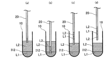
2. Second Embodiment A second embodiment of the dispensing method according to the present invention will be described. FIG. 4 is a flowchart showing the dispensing method of the present embodiment. FIG. 5 is a schematic diagram for explaining a part of the steps of the dispensing method of the present embodiment. FIG. 5A schematically shows a preparation state of the fourth suction process according to this embodiment, FIG. 5B schematically shows the fourth suction process according to this embodiment, and FIG. FIG. 5C schematically shows the fifth suction process according to the present embodiment, and FIG. 5D schematically shows the state of the tube after the fifth suction process according to the present embodiment.
2.1.構成
本実施形態の分注方法は、第1液体L1および第2液体L2が収容された第1容器10、並びに、第2液体L2および第3液体L3が収容された第3容器12から、管20を用いて第1液体L1および第3液体L3を第2容器20に分注する分注方法である。
2.1. Configuration The dispensing method of the present embodiment includes a tube from the
本実施形態における第1液体L1、第2液体L2、第1容器10、管20は、第1実施形態で述べたと同様であり、同じ符号を付して説明を省略する。
The first liquid L1, the second liquid L2, the
2.1.1.第3液体
第3液体L3は、第2液体L2と混和しない液体である。また、第3液体L3は、第2液体L2より比重が大きい液体である。第3液体L3は、このような性質を有するため、図5に示すように、第3容器12内に第3液体L3および第2液体L2が共存する場合には、第3液体L3と第2液体L2の間に(相分離)界面I32が形成され、界面I32の下側(第3容器12の底側)に第3液体L3が位置し、界面I32の上側(第3容器12の開口側)に第2液体L2が位置することになる。また、第3液体L3は、表面張力を有し、第3液体L3の体積が小さければ、第2液体L2中で液滴を形成することができる。
2.1.1. Third Liquid The third liquid L3 is a liquid that is immiscible with the second liquid L2. The third liquid L3 is a liquid having a larger specific gravity than the second liquid L2. Since the third liquid L3 has such properties, as shown in FIG. 5, when the third liquid L3 and the second liquid L2 coexist in the
第3液体L3は、水性、油性のいずれであってもよい。例えば、第3液体L3が水性である場合には、第2液体L2は、油性であることができ、また、その逆であってもよい。第3液体L3は、例えば、PCRの反応液を調製するための溶液であってもよい。第3液体L3を用いて調製される溶液がPCRの反応液である場合には、第3液体L3は、核酸(標的核酸)または反応に必要な試薬のうち少なくとも一種を含む溶液であることができる。この場合などは、第2容器30に残りの一部の試薬をあらかじめ収容しておいてもよい。また、第3液体L3としては、例えば、大気中の酸素によって酸化されやすい物質や、大気中の水等の分子と反応しやすい物質の溶液であってもよい。
The third liquid L3 may be either aqueous or oily. For example, when the third liquid L3 is aqueous, the second liquid L2 can be oily and vice versa. The third liquid L3 may be, for example, a solution for preparing a PCR reaction solution. When the solution prepared using the third liquid L3 is a PCR reaction liquid, the third liquid L3 may be a solution containing at least one of a nucleic acid (target nucleic acid) or a reagent necessary for the reaction. it can. In this case, the remaining part of the reagent may be stored in the
2.1.2.第3容器
第3容器12は、第1実施形態で述べた第1容器10と実質的に同様である。第3容器12は、本実施形態の分注方法によって分注される第3液体L3が収容される容器である。本実施形態の分注方法では、第3容器12には、第2液体L2も収容される。第3容器12の形状は、第3液体L3および第2液体L2が収容されたときに、第3容器12内に第3液体L3と第2液体L2との間の界面I32が形成され、第3液体L3が大気に接触しないようにできるかぎり任意である。第3容器12は、例えば、試験管、バイアル、生化学の分野で一般に使用される容器などであることができる。第3容器12の材質は、第1容器10と同様である。
2.1.2. Third Container The
2.2.分注方法
本実施形態の分注方法は、第1吸引工程と、第2吸引工程と、第3吸引工程と、第4吸引工程と、第5吸引工程と、第4吐出工程と、第5吐出工程と、第6吐出工程と、第7吐出工程と、第2吐出工程と、第3吐出工程と、を含む。
2.2. Dispensing Method The dispensing method of the present embodiment includes a first suction process, a second suction process, a third suction process, a fourth suction process, a fifth suction process, a fourth discharge process, and a fifth discharge process. It includes a discharge process, a sixth discharge process, a seventh discharge process, a second discharge process, and a third discharge process.
本実施形態における第1吸引工程、第2吸引工程、第3吸引工程、第2吐出工程と、第3吐出工程は、第2吐出工程が第7吐出工程に連続して行われる以外は、第1実施形態で述べたと同様であり、同じ符号を付して説明を省略する。本実施形態の分注方法は、第1実施形態と同様にして第1吸引工程から第3吸引工程(ステップS13)が行われ、その後、以下の工程が行われる。 The first suction process, the second suction process, the third suction process, the second discharge process, and the third discharge process in the present embodiment are the same as the first discharge process except that the second discharge process is performed continuously to the seventh discharge process. This is the same as that described in the first embodiment, and the same reference numerals are given and description thereof is omitted. In the dispensing method of the present embodiment, the first suction process to the third suction process (step S13) are performed as in the first embodiment, and then the following processes are performed.
図5(a)は、本実施形態の分注方法において、第3吸引工程(ステップS13)を経た後の管20の状態を示している。図5(a)に示すように、第3吸引工程を経た後の管20では、一端側から第2液体L2、第1液体L1、第2液体L2の順に液柱が形成され、この状態で管20を移動させることができる。
Fig.5 (a) has shown the state of the pipe |
2.2.1.第4吸引工程
第4吸引工程(ステップS14)は、第3吸引工程(ステップS13)の後で行われる。第4吸引工程と第3吸引工程との間には、例えば、管20の一端を第3容器12内に移動させるなどの、他の工程が行われてもよい。
2.2.1. Fourth Suction Process The fourth suction process (Step S14) is performed after the third suction process (Step S13). Between the fourth suction process and the third suction process, for example, another process such as moving one end of the
第4吸引工程では、第3容器12において管20の一端が第3液体L3と第2液体L2との界面I32より下の位置で、第3液体L3を管20の一端側から管20内に吸引する。第4吸引工程で界面I32より下の位置に配置される一端は、第3吸引工程で第2液体L2を吸引した一端である。第4吸引工程で吸引される第3液体L3の体積は特に限定されない。
In the fourth suction step, one end of the
図5(b)は、第4吸引工程において、第3容器12内に収容された第3液体L3を管20の一端側から吸引した様子を模式的に表している。第4吸引工程を経ると、管20の一端側に、第2液体L2の液柱に対して第1液体L1の液柱とは反対側に第3液体L3の液柱が形成される。
FIG. 5B schematically shows a state where the third liquid L3 accommodated in the
2.2.2.第5吸引工程
第5吸引工程(ステップS15)は、第4吸引工程(ステップS14)に連続して行われる。第5吸引工程では、第3容器12において管20の一端が界面I32より上の位置で、第2液体L2を管20の一端側から管20内に吸引する。第5吸引工程で界面I32より上の位置に配置される一端は、第4吸引工程で第3液体L3を吸引した一端である。
2.2.2. Fifth Suction Process The fifth suction process (Step S15) is performed continuously to the fourth suction process (Step S14). In the fifth suction step, the second liquid L2 is sucked into the
第5吸引工程で吸引される第2液体L2の体積は特に限定されない。第4吐出工程で、第2容器30にあらかじめ第2液体L2が収容されていない場合には、第5吸引工程で吸引された第2液体L2の体積は、当該第2液体L2が第4吐出工程で吐出された際に管20の一端の開口を浸す程度よりも大きいことが好ましい。
The volume of the second liquid L2 sucked in the fifth suction process is not particularly limited. When the second liquid L2 is not previously stored in the
図5(c)は、第5吸引工程において、第3容器12内に収容された第2液体L2を管20の一端側から吸引した様子を模式的に表している。第5吸引工程を経ると、管20の一端側に、第3液体L3の液柱の下に第2液体L2の液柱が形成される。図5(d)は、第5吸引工程を経た後の管20の状態を示している。図5(d)に示すように、第5吸引工程を経た後の管20では、一端側から第2液体L2、第3液体L3、第2液体L2、第1液体L1、第2液体L2の順に液柱が形成され、この状態で管20を移動させることができる。
FIG. 5C schematically shows a state in which the second liquid L2 accommodated in the
2.2.3.第4吐出工程
第4吐出工程(ステップS24)は、第5吸引工程(ステップS15)の後で行われる。第5吸引工程と第4吐出工程との間には、少なくとも第3容器12から管20を第2容器30に移動させる工程が行われる。第5吸引工程と第4吐出工程との間には、他の工程が行われてもよい。
2.2.3. Fourth Discharge Process The fourth discharge process (Step S24) is performed after the fifth suction process (Step S15). Between the fifth suction process and the fourth discharge process, at least a process of moving the
第4吐出工程では、第5吸引工程(ステップS15)で管20内に吸引された第2液体L2を、管20の一端側から第2容器30に吐出する。第4吐出工程で第2液体L2が吐出される一端は、第5吸引工程で第2液体L2を吸引した一端である。
In the fourth discharge step, the second liquid L2 sucked into the
第4吐出工程では、第2容器30に第2液体L2が吐出されるが、吐出された第2液体L2に管20の一端の開口が浸されるように行われる。第4吐出工程において、管20の一端の開口が浸されることにより、第5吐出工程で吐出される第3液体L3を大気に接触させないようにすることができる。また、第2液体L2に管20の一端の開口が浸されることにより、第5吐出工程で吐出される第3液体L3を管20から吐出させやすくすることができる。
In the fourth discharge step, the second liquid L2 is discharged into the
第4吐出工程で吐出される第2液体L2を収容する第2容器30には、あらかじめ第2液体L2が収容されていてもよい。このようにすれば、第4吐出工程の前後で第2液体L2に管20の一端の開口を浸しやすく、第5吐出工程で吐出される第3液体L3をさらに大気に接触させにくくすることができる。また、第2容器30にあらかじめ第2液体L2が収容されていると、第5吐出工程で吐出される第3液体L3を管20からさらに吐出させやすくすることができる。
The second liquid L2 may be stored in advance in the
2.2.4.第5吐出工程
第5吐出工程(ステップS25)は、第4吐出工程(ステップS24)に連続して行われる。第5吐出工程では、第4吸引工程(ステップS14)で管20内に吸引された第3液体L3を、管20の一端側から第2容器30に吐出する。第5吐出工程で第3液体L3が吐出される一端は、第4吐出工程で第3液体L3を吐出した一端である。
2.2.4. Fifth Discharge Process The fifth discharge process (Step S25) is performed continuously to the fourth discharge process (Step S24). In the fifth discharge step, the third liquid L3 sucked into the
第5吐出工程は、第2液体L2に管20の一端の開口が浸された状態で行われる。これにより、第5吐出工程で吐出される第3液体L3を大気に接触させないようにすることができる。また、第2吐出工程と同様に、第2液体L2に管20の一端の開口が浸されることにより、第5吐出工程で吐出される第3液体L3を管20から吐出させやすくなっている。
The fifth discharge step is performed in a state where the opening at one end of the
2.2.5.第6吐出工程
第6吐出工程(ステップS26)は、第5吐出工程(ステップS25)に連続して行われる。第6吐出工程では、第3吸引工程(ステップS13)で管20内に吸引された第2液体L2の一部を、管20の一端側から第2容器30に吐出する。第6吐出工程で第2液体L2が吐出される一端は、第3吸引工程で第2液体L2を吸引した一端である。
2.2.5. Sixth Discharge Process The sixth discharge process (Step S26) is performed continuously to the fifth discharge process (Step S25). In the sixth discharge step, a part of the second liquid L2 sucked into the
第6吐出工程は、第2液体L2に管20の一端の開口が浸された状態で行われる。これにより、第6吐出工程で吐出される第2液体L2が、第2容器30中の第2液体L2と合一し、第5吐出工程で吐出された第3液体L3を管20から離脱させることができる。
The sixth discharge step is performed in a state where the opening at one end of the
第6吐出工程で吐出される第2液体L2は、第3吸引工程で管20内に吸引された第2液体L2の一部である。これにより、第6吐出工程が終了した後、管20は、一端側から第2液体L2、第1液体L1、第2液体L2の順に液柱が形成され、この状態で管20を移動させることができる。
The second liquid L2 discharged in the sixth discharge process is a part of the second liquid L2 sucked into the
2.2.6.第7吐出工程
第7吐出工程(ステップS27)は、第6吐出工程(ステップS26)の後で行われる。第6吐出工程と第7吐出工程との間には、管20を他の第2容器30に移動させる工程が行われてもよい。第7吐出工程は、第6吐出工程を行った第2容器30と同一の第2容器30に対して行われてもよいし、第6吐出工程を行った第2容器30とは異なる第2容器30に対して行われてもよい。
2.2.6. Seventh Discharge Process The seventh discharge process (Step S27) is performed after the sixth discharge process (Step S26). Between the 6th discharge process and the 7th discharge process, the process of moving
第7吐出工程が、第6吐出工程を行った第2容器30と同一の第2容器30に対して行われる場合には、当該第2容器30内で、第1液体L1と第3液体L3とを混合することができる。また、第7吐出工程が、第6吐出工程を行った第2容器30とは異なる第2容器30に対して行われる場合には、各第2容器30に、第1液体L1と第3液体L3とをそれぞれ分注することができる。
When the seventh discharge process is performed on the
第7吐出工程では、第3吸引工程(ステップS13)で管20内に吸引され、第6吐出工程で管20内に残された第2液体L2の一部を、管20の一端側から第2容器30に吐出する。第7吐出工程で第2液体L2が吐出される一端は、第3吸引工程で第2液体L2を吸引した一端である。
In the seventh discharge process, a part of the second liquid L2 sucked into the
第7吐出工程では、第2容器30に第2液体L2が吐出されるが、吐出された第2液体L2に管20の一端の開口が浸されるように行われる。第7吐出工程において、管20の一端の開口が浸されることにより、第2吐出工程で吐出される第1液体L1を大気に接触させないようにすることができる。また、第2液体L2に管20の一端の開口が浸されることにより、第2吐出工程で吐出される第1液体L1を管20から吐出させやすくすることができる。
In the seventh discharge process, the second liquid L2 is discharged into the
第7吐出工程で吐出される第2液体L2を収容する第2容器30には、あらかじめ第2液体L2が収容されていてもよい。このようにすれば、第7吐出工程の前後で第2液体L2に管20の一端の開口を浸しやすく、第2吐出工程で吐出される第1液体L1をさらに大気に接触させにくくすることができる。また、第2容器30にあらかじめ第2液体L2が収容されていると、第2吐出工程で吐出される第1液体L1を管20からさらに吐出させやすくすることができる。
The second liquid L2 may be stored in advance in the
本実施形態の分注方法では、第7吐出工程の後、第1実施形態で述べたと同様に、第2吐出工程と、第3吐出工程とが行われる。 In the dispensing method of the present embodiment, after the seventh discharge process, the second discharge process and the third discharge process are performed as described in the first embodiment.
2.3.作用効果
本実施形態の分注方法によれば、第1液体L1および第3液体L3は、第1容器10および第3容器12に収容された状態、並びに各吸引工程および各吐出工程において、第2液体L2によって封じられた状態にあるので、気相(大気等)に接触しにくい。すなわち、本実施形態の分注方法によれば、第1液体L1および第3液体L3は、分注される際には、第2液体L2に接する状態で取り扱われるので大気等に接触しにくい。そのため、第1液体L1および第3液体L3からそれらの構成成分が気相に蒸発することや、気相から第1液体L1または第3液体L3へ水などの他の物質が混入することが抑制される。これにより、第1液体L1および第3液体L3の濃度の変動が小さく抑えられ、正確な分注を行うことができる。
2.3. Effects According to the dispensing method of the present embodiment, the first liquid L1 and the third liquid L3 are stored in the
また本実施形態の分注方法によれば、第5吐出工程(ステップS25)で、第3液体L3が第2液体L2中に吐出され、第2吐出工程(ステップS22)で、第1液体L1が第2液体L2中に吐出される。そのため、第5吐出工程および第2吐出工程において、管20内または管20の一端付近に第3液体L3および第1液体L1が残存しにくい。したがって精度よく第1液体L1および第3液体L3を第2容器30へと分注することができる。
Further, according to the dispensing method of the present embodiment, the third liquid L3 is discharged into the second liquid L2 in the fifth discharge step (step S25), and the first liquid L1 in the second discharge step (step S22). Is discharged into the second liquid L2. Therefore, in the fifth discharge process and the second discharge process, the third liquid L3 and the first liquid L1 hardly remain in the
さらに、本実施形態の分注方法によれば、第3液体L3および第1液体L1は第2液体L2によって包埋されて取り扱われるので、第3液体L3および第1液体L1が互いに混合しにくい。そのため、1つの管20を用いて複数種の液体を分注することができる。したがって、第1実施形態の変形実施形態と同様に、本実施形態においても、複数種の液体を複数の第2容器30にそれぞれ分注することや、複数種の液体を1つの第2容器30に分注することができる。
Furthermore, according to the dispensing method of the present embodiment, since the third liquid L3 and the first liquid L1 are embedded and handled by the second liquid L2, the third liquid L3 and the first liquid L1 are difficult to mix with each other. . Therefore, a plurality of types of liquids can be dispensed using one
3.第3実施形態
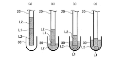
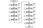
本発明に係る分注方法の第3実施形態を述べる。図6は、分注方法を示すフローチャートである。図7および図8は、それぞれ本実施形態の分注方法の工程の一部を説明する模式図である。図7(a)は、本実施形態に係る第5吸引工程を模式的に示し、図7(b)および図7(c)は、本実施形態に係る混合工程を模式的に示し、図7(d)および図7(e)は、本実施形態に係る混合工程を経た後の状態を模式的に示している。図8(a)は、本実施形態に係る第8吐出工程を模式的に示し、図8(b)は、本実施形態に係る第10吐出工程を模式的に示している。
3. Third Embodiment A third embodiment of the dispensing method according to the present invention will be described. FIG. 6 is a flowchart showing the dispensing method. 7 and 8 are schematic views for explaining a part of the steps of the dispensing method of the present embodiment. FIG. 7A schematically shows the fifth suction step according to the present embodiment, and FIGS. 7B and 7C schematically show the mixing step according to the present embodiment. (D) and FIG.7 (e) have shown typically the state after passing through the mixing process which concerns on this embodiment. FIG. 8A schematically shows the eighth discharge process according to this embodiment, and FIG. 8B schematically shows the tenth discharge process according to this embodiment.
3.1.構成
本実施形態の分注方法は、第1液体L1および第2液体L2が収容された第1容器10、および、第2液体L2および第3液体L3が収容された第3容器12から、一端が開放され他端側に液溜22が接続された管20を用いて、第1液体L1および第3液体L3を第2容器30に分注する分注方法である。
3.1. Configuration The dispensing method of the present embodiment has one end from the
本実施形態における第1液体L1、第2液体L2、第3液体L3、第1容器10、第3容器12、管20は、第1実施形態または第2実施形態で述べたと同様であり、同じ符号を付して説明を省略する。本実施形態では、管20の他端側に液溜22が接続される。
The first liquid L1, the second liquid L2, the third liquid L3, the
3.1.1.液溜
液溜22は、管20の他端側に接続される。液溜22は、管20の内径よりも大きい内径を有する容室である。液溜22は、管20と一体であっても、管20に着脱可能であってもよい。管20に液溜22が接続されても、液溜22の管20とは異なる位置にポンプ等を接続することで、管20は他端側から液溜22を介して液体を吸引することができる。液溜22の形状は、管20の他端側から管20内の液体が液溜22に吸引された際に液体がプラグを形成しない形状であれば特に限定されない。
3.1.1. Liquid reservoir The
液溜22から管20へ液体を送液する場合は、液溜22内で液体のプラグが形成されないため、液溜22内の液体は、管20から液溜22に吸引された順番とは独立に、比重の大きい順番で送液される。液溜22内を吸引、加圧する手段は、管20で説明した手段と同様である。また、液溜22の材質は、管20の材質と同様である。
When liquid is sent from the
さらに、液溜22は、少なくとも内壁が疎水性を有することが好ましい。液溜22の少なくとも内壁が疎水性を有すると、分注する液体が水性である場合に、該液体が液溜22に付着しにくい。
Furthermore, it is preferable that at least the inner wall of the
3.2.分注方法
本実施形態の分注方法は、第1吸引工程と、第2吸引工程と、第3吸引工程と、第4吸引工程と、第5吸引工程と、混合工程と、第8吐出工程と、第9吐出工程と、第10吐出工程と、を含む。
3.2. Dispensing method The dispensing method of the present embodiment includes a first suction process, a second suction process, a third suction process, a fourth suction process, a fifth suction process, a mixing process, and an eighth discharge process. And a ninth discharge step and a tenth discharge step.
本実施形態における第1吸引工程、第2吸引工程、第3吸引工程、第4吸引工程、第5吸引工程は、第1実施形態および第2実施形態で述べたと同様であり、同じ符号を付して説明を省略する。本実施形態の分注方法は、第2実施形態と同様に第5吸引工程(ステップS15)まで行われ、その後、以下の工程が行われる。 The first suction process, the second suction process, the third suction process, the fourth suction process, and the fifth suction process in this embodiment are the same as those described in the first embodiment and the second embodiment, and are denoted by the same reference numerals. Therefore, the description is omitted. The dispensing method of the present embodiment is performed up to the fifth suction step (step S15) as in the second embodiment, and then the following steps are performed.
図7(a)は、本実施形態の分注方法において、第5吸引工程(ステップS15)を経た後の管20が第3容器12に配置された状態を示している。図7(a)に示すように、第5吸引工程を経た後の管20では、一端側から第2液体L2、第3液体L3、第2液体L2、第1液体L1、第2液体L2の順に液柱が形成されている。
FIG. 7A shows a state in which the
3.2.1.混合工程
混合工程(ステップS30)は、第5吸引工程(ステップ15)中または第5吸引工程(ステップ15)の後で行われる。図7(b)ないし(d)の例は、混合工程が第5吸引工程中に行われる様子を表している。図7(e)は、混合工程が、第5吸引工程を終えた後、管20を大気中に移動してから行われた後の様子を表している。
3.2.1. Mixing Step The mixing step (step S30) is performed during the fifth suction step (step 15) or after the fifth suction step (step 15). The examples of FIGS. 7B to 7D show a state in which the mixing step is performed during the fifth suction step. FIG. 7E shows a state after the mixing process is performed after moving the
混合工程では、管20内に第5吸引工程で吸引された第2液体L2の少なくとも一部が残るように、液溜22に管20内の各液体(第1吸引工程で吸引された第2液体L2、第2吸引工程で吸引された第1液体L1、第3吸引工程で吸引された第2液体L2、および第4吸引工程で吸引された第3液体、並びに、必要に応じて、第5吸引工程で吸引された第2液体の一部)を吸引する。そして、第2吸引工程で管20内に吸引された第1液体L1、および第4吸引工程で管20内に吸引された第3液体L3を、液溜22内で混合させて第4液体L4とする。かつ、第1吸引工程で吸引された第2液体L2、第3吸引工程で吸引された第2液体L2、および、場合によっては第5吸引工程で吸引された第2液体L2を混合させる。
In the mixing step, each liquid in the tube 20 (the second suction sucked in the first suction step) is stored in the
本明細書において、「A工程がB工程中に行われる」との表現は、B工程においてA工程が行われることを指す。したがって本実施形態の混合工程が第5吸引工程中に行われる場合は、混合工程が第5吸引工程において第2液体を管内に吸引しながら行われる場合のことを指す。またなお、本実施形態の混合工程が第5吸引工程の後に行われる場合は、混合工程が気体または他の液体を管内に吸引しながら行われる場合のことを指す。 In this specification, the expression “A process is performed during the B process” indicates that the A process is performed in the B process. Therefore, when the mixing process of this embodiment is performed during the fifth suction process, the mixing process is performed while suctioning the second liquid into the tube in the fifth suction process. In addition, when the mixing step of the present embodiment is performed after the fifth suction step, it indicates a case where the mixing step is performed while sucking a gas or other liquid into the tube.
図7(b)に示すように、液溜22内に、第1吸引工程で吸引された第2液体L2および第2吸引工程で吸引された第1液体L1が導入されると、第1液体L1のプラグ形状が解けて、液溜22内に第1液体L1の液滴が形成される。続いて、図7(c)に示すようにさらに吸引すると、液溜22内に、第3吸引工程で吸引された第2液体L2および第4吸引工程で吸引された第3液体L3が導入される。液溜22に導入された第2液体L2同士は合一するので、第2液体L2よりも比重が大きい第1液体L1の液滴と第3液体L3とが液溜22内において接触する。そして、図7(d)に示すように、第1液体L1および第3液体L3との混合液体である第4液体L4の液滴が液溜22内に形成される。この状態においても、液溜22内では、第4液体L4のほうが第2液体L2よりも比重が大きいため、第4液体L4は、第2液体L2に包埋されて大気に接触しにくい。なお、混合は液溜22の管20に接続されている側を下にして行うことが好ましい。これにより、液溜22に空気が存在しても、第1液体L1、第3液体L3、および第4液体L4をさらに空気に触れにくくできる。
As shown in FIG. 7B, when the second liquid L2 sucked in the first suction step and the first liquid L1 sucked in the second suction step are introduced into the
第4液体L4は、第1液体L1および第3液体L3との混合液体である。例えば、第1液体L1がPCRにおける増幅対象の核酸の水溶液であり、第2液体L2がPCRにおける反応に必要な試薬であれば、第4液体L4はPCRの反応液である。 The fourth liquid L4 is a mixed liquid of the first liquid L1 and the third liquid L3. For example, if the first liquid L1 is an aqueous solution of nucleic acid to be amplified in PCR and the second liquid L2 is a reagent necessary for the reaction in PCR, the fourth liquid L4 is a PCR reaction liquid.
混合工程を経ると、液溜22内に第4液体L4の液滴と第2液体L2が存在し、管20内には、第5吸引工程で吸引された第2液体L2の液柱が存在する状態となる。そして、この状態で管20を移動させることができる。
After the mixing step, the
3.2.2.第8吐出工程
第8吐出工程(ステップS28)は、混合工程(ステップS30)の後に行われる。第8吐出工程では、第5吸引工程(ステップS15)で管20内に吸引された第2液体L2のうち、混合工程を経て管20内に残された第2液体L2を、管20の一端側から第2容器30に吐出する。混合工程と第8吐出工程との間には、他の工程が行われてもよい。第8吐出工程で第2液体L2が吐出される一端は、第5吸引工程で第2液体L2を吸引した一端である。
3.2.2. Eighth discharge process The eighth discharge process (step S28) is performed after the mixing process (step S30). In the eighth discharge process, out of the second liquid L2 sucked into the
第8吐出工程は、第2容器30に第2液体L2が吐出されるが、吐出された第2液体L2に管20の一端の開口が浸されるように行われる。第8吐出工程において、管20の一端の開口が浸されることにより、第9吐出工程で吐出される第4液体L4を大気に接触させにくくすることができる。また、第2液体L2に管20の一端の開口が浸されることにより、第9吐出工程で吐出される第4液体L4を管20から吐出させやすくすることができる。
The eighth discharge step is performed so that the second liquid L2 is discharged to the
第8吐出工程で吐出される第2液体L2を収容する第2容器30には、あらかじめ第2液体L2が収容されていてもよい。このようにすれば、第8吐出工程の前後で第2液体L2に管20の一端の開口を浸しやすく、第9吐出工程で吐出される第4液体L4をさらに大気に接触させにくくすることができる。また、第2容器30にあらかじめ第2液体L2が収容されていると、第9吐出工程で吐出される第4液体L4を管20からさらに吐出させやすくすることができる。
The second liquid L2 may be stored in advance in the
図8(a)は、第8吐出工程で管20が、第2容器30内に配置された状態を示している。なお、図8(a)は、第2容器30内にあらかじめ第2液体L2が収容されている状態を示している。
FIG. 8A shows a state in which the
3.2.3.第9吐出工程
第9吐出工程(ステップS29)は、第8吐出工程(ステップS28)に連続して行われる。第9吐出工程では、混合工程(ステップS30)で液溜22内に形成された第4液体L4を、管20の一端側から第2容器30に吐出する。第9吐出工程で第4液体L4が吐出される一端は、管20の液溜22が接続されていない一端である。
3.2.3. Ninth Discharge Process The ninth discharge process (Step S29) is performed continuously to the eighth discharge process (Step S28). In the ninth discharge step, the fourth liquid L4 formed in the
第9吐出工程は、第2容器30内の第2液体L2に管20の一端の開口が浸された状態で行われる。これにより、第9吐出工程で吐出される第4液体L4を大気に接触させないようにすることができる。また、第2吐出工程と同様に、第2液体L2に管20の一端の開口が浸されることにより、第9吐出工程で吐出される第4液体L4を管20から吐出させやすくなっている。
The ninth discharge step is performed in a state where the opening of one end of the
3.2.4.第10吐出工程
第10吐出工程(ステップS210)は、第9吐出工程(ステップS29)に連続して行われる。第10吐出工程では、混合工程(ステップS30)で混合された第2液体L2の少なくとも一部を、管20の一端側から第2容器30に吐出する。第10吐出工程で第2液体L2が吐出される一端は、第1吸引工程で第2液体L2を吸引した一端である。
3.2.4. Tenth Discharge Process The tenth discharge process (Step S210) is performed continuously to the ninth discharge process (Step S29). In the tenth discharge process, at least a part of the second liquid L2 mixed in the mixing process (step S30) is discharged from the one end side of the
第10吐出工程は、第2液体L2に管20の一端の開口が浸された状態で行われる。これにより、第10吐出工程で吐出される第2液体L2が、第2容器30中の第2液体L2と合一し、第9吐出工程で吐出された第4液体L4を管20から離脱させることができる。第10吐出工程で吐出される第2液体L2は、混合工程で混合された第2液体L2の一部であっても全部であってもよい。
The tenth discharge step is performed in a state where the opening at one end of the
図8(b)は、第10吐出工程が終了し、第10吐出工程で第2液体L2の一部が吐出された状態を示しており、管20内に第2液体L2の液柱が残存し、第4液体L4が管20から離脱した状態を示している。第10吐出工程では、第2容器30中の第2液体L2に管20の一端の開口が浸されて行われるため、第4液体L4が大気に接触することが抑制される。また、第10吐出工程は、第2容器30中の第2液体L2に管20の一端の開口が浸されて行われるため、第10吐出工程によって、図示のように、管20内の第2液体L2の液柱と第2容器30内の第2液体L2とを連続させることができる。そのため、第4液体L4を管20の一端の開口から容易に離脱させることができる。なお、図8(b)では、離脱した第4液体L4が液滴を形成している例を示している。
FIG. 8B shows a state where the tenth discharge process is completed and a part of the second liquid L2 is discharged in the tenth discharge process, and the liquid column of the second liquid L2 remains in the
3.3.作用効果
本実施形態の分注方法によれば、第1液体L1および第3液体L3を確実に混合することができる。すなわち、本実施形態の分注方法によれば、混合工程において第1液体L1および第3液体L3の液滴を、液溜22中で合一させて第4液体L4の液滴を形成できるので、第1液体L1および第3液体L3を第2容器30にそれぞれ吐出した後に第2容器30内で両者の液滴を合一させる場合に比べて、第1液体L1と第3液体L3とを接触させやすいので、より確実に第1液体L1および第3液体L3を混合することができる。
3.3. Action Effect According to the dispensing method of the present embodiment, the first liquid L1 and the third liquid L3 can be reliably mixed. That is, according to the dispensing method of the present embodiment, the droplets of the first liquid L1 and the third liquid L3 can be united in the
また、本実施形態の分注方法によれば、第1液体L1、第3液体L3および第4液体L4は、第1容器10および第3容器12に収容された状態、並びに各吸引工程、混合工程および各吐出工程において、第2液体L2によって封じられるので、一貫して気相に接触しにくい。すなわち、本実施形態の分注方法によれば、第1液体L1、第3液体L3および第4液体L4は、分注される際には、第2液体に接する状態で取り扱われるので大気等に接触しにくい。そのため、第1液体L1、第3液体L3または第4液体L4からそれらの構成成分が気相に蒸発することや、気相から第1液体L1、第3液体L3または第4液体L4へ水などの他の物質が混入することが抑制される。これにより、第1液体L1、第3液体L3および第4液体L4の濃度の変動が小さく抑えられ、正確な分注を行うことができる。
Moreover, according to the dispensing method of this embodiment, the 1st liquid L1, the 3rd liquid L3, and the 4th liquid L4 are the state accommodated in the
また、本実施形態の分注方法によれば、第9吐出工程で、第4液体L4が第2液体L2中に吐出される。そのため、第9吐出工程において、管20内または管20の一端付近に第4液体L4が残存しにくい。したがって精度よく第4液体L4を第2容器30へと分注することができる。
Further, according to the dispensing method of the present embodiment, the fourth liquid L4 is discharged into the second liquid L2 in the ninth discharge step. For this reason, in the ninth discharge step, the fourth liquid L4 hardly remains in the
4.第4実施形態
本発明に係る分注方法の第4実施形態を述べる。図9は、本実施形態に係る分注方法を示すフローチャートである。図10は、本実施形態の分注方法の工程の一部を説明する模式図である。図10(a)は、本実施形態で用いる第2容器を模式的に示し、図10(b)は、本実施形態に係る第1吐出工程を模式的に示し、図10(c)は、本実施形態に係る第11吐出工程を経た後の状態を模式的に示している。
4). Fourth Embodiment A fourth embodiment of the dispensing method according to the present invention will be described. FIG. 9 is a flowchart showing the dispensing method according to the present embodiment. FIG. 10 is a schematic diagram for explaining a part of the steps of the dispensing method of the present embodiment. FIG. 10A schematically shows the second container used in this embodiment, FIG. 10B schematically shows the first discharge step according to this embodiment, and FIG. The state after passing through the 11th discharge process concerning this embodiment is shown typically.
4.1.構成
本実施形態の分注方法は、第1液体L1および第2液体L2が収容された第1容器10から、管20を用いて第1液体L1を、第5液体L5が収容された第2容器30に分注する分注方法である。
4.1. Configuration In the dispensing method of the present embodiment, the first liquid L1 and the second liquid L5 are accommodated from the
本実施形態における第1液体L1、第2液体L2、第1容器10、管20は、第1実施形態または第2実施形態で述べたと同様であり、同じ符号を付して説明を省略する。本実施形態では、第2容器30にあらかじめ第5液体L5が収容されている。
The first liquid L1, the second liquid L2, the
4.1.1.第5液体
第5液体L5は、第1液体L1と混和しない液体である。また、第5液体L5は、第1液体L1よりも比重が小さい液体である。第5液体L5としては、第2液体L2と混和する液体が使用される。第5液体L5は、第2液体L2と同様に、第1液体L1が水性である場合には油性であることができる。第1液体L1がPCRの反応液である場合には、第5液体L5は、オイルであることができる。このようなオイルとしては、例えば、ジメチルシリコーンオイル等のシリコーン系オイル、パラフィン系オイルおよびミネラルオイル並びにそれらの混合物を挙げることができる。
4.1.1. Fifth Liquid The fifth liquid L5 is a liquid that is immiscible with the first liquid L1. The fifth liquid L5 is a liquid having a specific gravity smaller than that of the first liquid L1. As the fifth liquid L5, a liquid miscible with the second liquid L2 is used. The fifth liquid L5 can be oily when the first liquid L1 is aqueous, like the second liquid L2. When the first liquid L1 is a PCR reaction liquid, the fifth liquid L5 can be oil. Examples of such oils include silicone oils such as dimethyl silicone oil, paraffin oils and mineral oils, and mixtures thereof.
4.2.分注方法
本実施形態の分注方法は、第6吸引工程と、第2吸引工程と、第3吸引工程と、第1吐出工程と、第2吐出工程と、第11吐出工程と、を含む。
4.2. Dispensing Method The dispensing method of the present embodiment includes a sixth suction process, a second suction process, a third suction process, a first discharge process, a second discharge process, and an eleventh discharge process. .
本実施形態における第2吸引工程、第3吸引工程、第1吐出工程、第2吐出工程は、第2吸引工程が第6吸引工程の後で行われる以外は、第1実施形態で述べたと同様であり、同じ符号を付して説明を省略する。図10(a)は、第2容器30に第5液体L5が収容された状態を示す。
The second suction process, the third suction process, the first discharge process, and the second discharge process in the present embodiment are the same as described in the first embodiment except that the second suction process is performed after the sixth suction process. Therefore, the same reference numerals are given and the description is omitted. FIG. 10A shows a state where the fifth liquid L5 is stored in the
4.2.1.第6吸引工程
第6吸引工程(ステップS16)では、第2液体L2または第5液体L5を管20の一端側から管20内に吸引する。第6吸引工程で第2液体L2が吸引される場合は、第1容器10内に収容された第2液体L2であっても、他の容器に収容された第2液体L2であってもよい。第6吸引工程で第5液体L5が吸引される場合は、第2容器30内に収容された第5液体L5であっても、他の容器に収容された第5液体L5であってもよい。第6吸引工程で吸引される第2液体L2または第5液体L5の体積は特に限定されないが、第2吸引工程で吸引される第1液体L1が管20内の気体の影響を受けない程度の体積で吸引されることが好ましい。
4.2.1. Sixth Suction Step In the sixth suction step (step S16), the second liquid L2 or the fifth liquid L5 is sucked into the
第6吸引工程は、管20の内壁に第2液体L2または第5液体L5を接触させて、第2吸引工程で吸引される第1液体L1が管20の内壁に付着しにくくし、および第2吸引工程で吸引される第1液体L1が管20内で移動しやすくする。第6吸引工程を行うことにより、第2吸引工程で吸引される第1液体L1が管20内の気体と接触しにくくすることができる。
In the sixth suction step, the second liquid L2 or the fifth liquid L5 is brought into contact with the inner wall of the
第6吸引工程を経ると、管20の一端側に、第2液体L2の液柱が形成される。そして、本実施形態では、第6吸引工程(ステップS16)の後で第2吸引工程(ステップS12)が行われ、第1実施形態で述べたと同様に、第3吸引工程(ステップS13)、第1吐出工程(ステップS21)、第2吐出工程(ステップS22)の順で各工程が行われる。第2吐出工程を経ると、管20内に第2液体L2または第5液体L5の液柱が残存し、第1液体L1が管20から出て、第1液体L1が管20の一端に接触している状態となる(図3(c)参照)。
After the sixth suction step, a liquid column of the second liquid L2 is formed on one end side of the
なお、本実施形態では、第2容器30内には、あらかじめ第5液体L5が収容されているが、第1吐出工程を経ると第5液体L5と第2液体L2が混合される。したがって、第11吐出工程においては第2容器30内には、第5液体L5および第2液体L2の混合液体が収容されている。
In the present embodiment, the fifth liquid L5 is stored in the
4.2.2.第11吐出工程
第11吐出工程(ステップS211)は、第2吐出工程(ステップS22)に連続して行われる。第11吐出工程では、第6吸引工程(ステップS16)で管20内に吸引された第2液体L2または第5液体L5の少なくとも一部を、管20の一端側から第2容器30に吐出する。第11吐出工程で第2液体L2または第5液体が吐出される一端は、第6吸引工程で第2液体L2または第5液体L5を吸引した一端である。
4.2.2. Eleventh discharge process The eleventh discharge process (step S211) is performed continuously to the second discharge process (step S22). In the eleventh discharge process, at least a part of the second liquid L2 or the fifth liquid L5 sucked into the
第11吐出工程は、第2容器30内の第5液体L5および第2液体L2の混合液体に管20の一端の開口が浸された状態で行われる。これにより、第11吐出工程で吐出される第2液体L2または第5液体L5が、第2容器30中の第5液体L5および第2液体L2の混合液体と合一し、第2吐出工程で吐出された第1液体L1を管20から離脱させることができる。
The eleventh discharge step is performed in a state where the opening at one end of the
第11吐出工程で吐出される第2液体L2または第5液体L5は、第6吸引工程で管20内に吸引された第2液体L2または第5液体L5の一部でも全部でもよい。
The second liquid L2 or the fifth liquid L5 discharged in the eleventh discharge process may be part or all of the second liquid L2 or the fifth liquid L5 sucked into the
図10(c)は、第11吐出工程が終了し、第11吐出工程で第5液体L5の一部が吐出された状態を示しており、管20内に第5液体L5の液柱が残存し、第1液体L1が管20から離脱した状態を示している。第11吐出工程では、第2容器30中の第5液体L5および第2液体L2の混合液体に管20の一端の開口が浸されて行われるため、第1液体L1が大気に接触しにくい。また、第11吐出工程は、第2容器30中の第5液体L5および第2液体L2の混合液体に管20の一端の開口が浸されて行われるため、第11吐出工程によって、図示のように、管20内の第5液体L5の液柱と第2容器30内の第5液体L5および第2液体L2の混合液体とを連続させることができる。そのため、第1液体L1を管20の一端の開口から容易に離脱させることができる。なお、図10(c)では、離脱した第1液体L1が液滴を形成している例を示している。
FIG. 10C shows a state where the eleventh discharge process is completed and a part of the fifth liquid L5 is discharged in the eleventh discharge process, and the liquid column of the fifth liquid L5 remains in the
4.3.作用効果
本実施形態の分注方法によれば、第1液体L1は、第1容器10に収容された状態、並びに各吸引工程および各吐出工程において、第2液体L2または第5液体L5によって封じられた状態であるので、気相(大気等)に接触しにくい。すなわち、本実施形態の分注方法によれば、第1液体L1は、第1容器10から第2容器30に分注される際には、第2液体L2または第5液体L5に接する状態で取り扱われ大気等に接触しにくい。そのため、第1液体L1から構成成分が気相に蒸発することや、気相から第1液体L1へ水などの他の物質が混入することが抑制される。これにより、第1液体L1の溶媒および溶質の濃度の変動が小さく抑えられ、正確な分注を行うことができる。
4.3. Effects According to the dispensing method of the present embodiment, the first liquid L1 is sealed with the second liquid L2 or the fifth liquid L5 in the state accommodated in the
また、本実施形態の分注方法によれば、第2吐出工程で、第1液体L1が、第5液体L5および第2液体L2の混合液体中に吐出される。そのため、第2吐出工程において、管20内または管20の一端付近に第1液体L1が残存しにくい。したがって精度よく第1液体L1を第1容器10から第2容器30へと分注することができる。
Further, according to the dispensing method of the present embodiment, the first liquid L1 is discharged into the mixed liquid of the fifth liquid L5 and the second liquid L2 in the second discharge step. Therefore, in the second discharge process, the first liquid L1 is unlikely to remain in the
5.その他の実施形態
上述の各実施形態において、第2液体L2および第5液体L5の少なくとも一方に導電性を有してもよい。
5. Other Embodiments In each of the above-described embodiments, at least one of the second liquid L2 and the fifth liquid L5 may have conductivity.
第2液体L2または第5液体L5に導電性を付与する方法としては、添加剤を添加することが挙げられる。このような添加剤としては、カルビノール変性オイルやトリメチルシロキシケイ酸とシクロペンタシロキサンの混合物等がある。添加剤の好ましい添加量としては、第2液体L2または第5液体L5の電気抵抗率が、1012[Ω・m]以下となる程度である。この場合の添加剤の添加量は3%以下である。 As a method for imparting conductivity to the second liquid L2 or the fifth liquid L5, an additive may be added. Examples of such additives include carbinol-modified oil and a mixture of trimethylsiloxysilicic acid and cyclopentasiloxane. A preferable addition amount of the additive is such that the electrical resistivity of the second liquid L2 or the fifth liquid L5 is 10 12 [Ω · m] or less. In this case, the additive amount is 3% or less.
第2液体L2および第5液体L5の少なくとも一方が導電性を有すると、第1液体L1、第3液体L3、第4液体L4、管20、第1容器10、第3容器12、および第2容器30が帯電しにくくなるので、より安定した分注方法とすることができる。
When at least one of the second liquid L2 and the fifth liquid L5 has conductivity, the first liquid L1, the third liquid L3, the fourth liquid L4, the
特に、各実施形態において、ナノリットルの規模の液体を扱う場合には、第2液体L2および第5液体L5の少なくとも一方が帯電していると、各種の不具合が生じる可能性が高くなる。不具合としては、具体的には、各工程における吸引、吐出動作の際、および管20の移動の際に、液体が管20から離脱しにくかったり、液体が容器から飛び出したりすることが挙げられる。しかし、第2液体L2および第5液体L5の少なくとも一方に導電性を付与すれば、このような不具合を生じにくくすることができる。
In particular, in each embodiment, when handling a liquid of a nanoliter scale, if at least one of the second liquid L2 and the fifth liquid L5 is charged, there is a high possibility that various problems will occur. Specifically, the problems include that it is difficult for the liquid to separate from the
上記第4実施形態において、第5液体L5に導電性を付与すれば、第1液体L1および第2液体L2の少なくとも一方が帯電した場合に、各吐出工程において、管20の先端付近で第1液体L1および第2液体L2の少なくとも一方が、第5液体L5との間の静電的な引力または斥力によって、予期せぬ挙動を示すことを抑制することができる。そのため、より確実に第1液体L1を第1容器10から第2容器30へと分注することができる。
In the fourth embodiment, by providing conductivity to the fifth liquid L5, when at least one of the first liquid L1 and the second liquid L2 is charged, the first liquid L1 near the tip of the
上記第1実施形態ないし第4実施形態において、第2液体L2に導電性を付与すれば、各液体が帯電した場合に、各吐出工程において、管20の先端付近で少なくとも第1液体L1が、第2容器30またはその内容物との間の静電的な引力または斥力によって、予期せぬ挙動を示すことを抑制することができる。そのためより確実に第1液体L1を第2容器30へと分注することができる。
In the first to fourth embodiments, by providing conductivity to the second liquid L2, when each liquid is charged, at each discharge step, at least the first liquid L1 is near the tip of the
なお、本発明の分注方法は、上述の各実施形態、変形実施形態、およびその他の実施形態のそれぞれの一部または全部の工程を互いに適宜組み合わせてもよいことは容易に理解されるであろう。 In the dispensing method of the present invention, it is easily understood that some or all of the steps of the above-described embodiments, modified embodiments, and other embodiments may be appropriately combined with each other. Let's go.
6.分注装置
上記各実施形態の分注方法は、作業者が行ってもよいが、以下に説明する分注装置を用いて行うことができる。以下に分注装置100を例示する。図11は、分注装置100を模式的に示す図である。分注装置100は、管20、支持体50、ポンプ60、ステージ70、移動機構80および制御手段90を有する。
6). Dispensing Device The dispensing method of each of the above embodiments may be performed by an operator, but can be performed using a dispensing device described below. The dispensing
管20は、上記実施形態で述べた管20であり、一端が支持体50から下方に向かって突出するように、支持体50に支持されている。管20の他端側には、ポンプ60が接続されている。
The
支持体50は、管20を支持する。支持体50は、例えば、管20を取り替えることのできる機構を有してもよい。支持体50は、移動機構80によって移動されることができる。
The
ポンプ60は、管20内を他端側から吸引することと、管20内に他端側から圧力を印加することとができる。ポンプ60の吸引および加圧の動作は、制御手段90によって制御されることができる。
The
ステージ70は、該ステージ70上に容器等を載置することができる。図11の例では、第1容器10および第2容器30がステージ70上に載置されている。ステージ70は、移動機構80によって移動されることができる。
The
移動機構80は、支持体50およびステージ70の相対的な位置関係を変化させる機構である。図示の例では、移動機構80は、支持体50およびステージ70の両者に設けられているが、いずれか一方に設けられてもよい。移動機構80は、支持体50およびステージ70の相対的な位置関係を変化させて、管20を各容器間で移動させること、および各容器内の管20の一端の位置を変化させることができる。
The moving
制御手段90は、ポンプ60および移動機構80の動作を制御することができる。制御手段90は、例えば、電子計算機(パーソナルコンピューター等)で構成することができる。制御手段90は、上述した分注方法に従ってポンプ60および移動機構80の動作を制御するプログラムを備えることができる。
The control means 90 can control the operation of the
以上のような構成により、分注装置100によれば、上記実施形態の分注方法を行うことができ、例えば、第1容器10から第2容器30へ第1液体L1を分注することができる。
With the configuration as described above, according to the
本発明は、以上説明した実施形態に限定されるものではなく、種々の変形が可能である。例えば、本発明は、実施形態で説明した構成と実質的に同一の構成(例えば、機能、方法および結果が同一の構成、あるいは目的および効果が同一の構成)を含む。また、本発明は、実施形態で説明した構成の本質的でない部分を置き換えた構成を含む。また、本発明は、実施形態で説明した構成と同一の作用効果を奏する構成または同一の目的を達成することができる構成を含む。また、本発明は、実施形態で説明した構成に公知技術を付加した構成を含む。 The present invention is not limited to the embodiment described above, and various modifications are possible. For example, the present invention includes substantially the same configuration (for example, a configuration having the same function, method, and result, or a configuration having the same purpose and effect) as the configuration described in the embodiment. In addition, the invention includes a configuration in which a non-essential part of the configuration described in the embodiment is replaced. In addition, the present invention includes a configuration that achieves the same effect as the configuration described in the embodiment or a configuration that can achieve the same object. In addition, the invention includes a configuration in which a known technique is added to the configuration described in the embodiment.
10…第1容器、12…第3容器、20…管、22…液溜、30…第2容器、50…支持体、60…ポンプ、70…ステージ、80…移動機構、90…制御手段、100…分注装置、L1…第1液体、L2…第2液体、L3…第3液体、L4…第4液体、L5…第5液体、I12,I32…界面
DESCRIPTION OF
Claims (8)
前記第2液体を前記管の一端から前記管の内部に吸引する第1吸引工程と、
前記第1容器に収容された前記第1液体を前記管の前記一端から前記管の内部に吸引する第2吸引工程と、
前記第1容器に収容された前記第2液体を前記管の前記一端から前記管の内部に吸引する第3吸引工程と、
前記第3吸引工程で前記管の内部に吸引された前記第2液体を前記第2容器に吐出する第1吐出工程と、
前記第2吸引工程で前記管の内部に吸引された前記第1液体を前記第2容器における前記第2液体中に吐出する第2吐出工程と、
前記第1吸引工程で前記管の内部に吸引された前記第2液体の少なくとも一部を前記第2容器に吐出する第3吐出工程と、
を含む、分注方法。 A portion for dispensing the first liquid into the second container using a tube from the first container containing the first liquid and the second liquid which is immiscible with the first liquid and has a specific gravity smaller than that of the first liquid. Ordering method,
A first suction step of sucking the second liquid from one end of the tube into the tube;
A second suction step of sucking the first liquid contained in the first container from the one end of the tube into the tube;
A third suction step of sucking the second liquid contained in the first container from the one end of the tube into the tube;
A first discharge step of discharging the second liquid sucked into the tube in the third suction step into the second container;
A second discharge step of discharging the first liquid sucked into the tube in the second suction step into the second liquid in the second container;
A third discharge step of discharging at least a part of the second liquid sucked into the tube in the first suction step into the second container;
Including dispensing method.
前記第2液体を前記管の一端から前記管の内部に吸引する第1吸引工程と、
前記第1容器に収容された前記第1液体を前記管の前記一端から前記管の内部に吸引する第2吸引工程と、
前記第1容器に収容された前記第2液体を前記管の前記一端から前記管の内部に吸引する第3吸引工程と、
前記第3容器に収容された前記第3液体を前記管の前記一端から前記管の内部に吸引する第4吸引工程と、
前記第3容器に収容された前記第2液体を前記管の前記一端から前記管の内部に吸引する第5吸引工程と、
前記第5吸引工程で前記管の内部に吸引された前記第2液体を前記第2容器に吐出する第1吐出工程と、
前記第4吸引工程で前記管の内部に吸引された前記第3液体を前記第2容器に吐出する第2吐出工程と、
前記第3吸引工程で前記管の内部に吸引された前記第2液体の一部を前記第2容器に吐出する第3吐出工程と、
前記第3吐出工程で管の内部に残された前記第2液体を前記第2容器に吐出する第4吐出工程と、
前記第2吸引工程で前記管の内部に吸引された前記第1液体を前記第2容器に吐出する第5吐出工程と、
前記第1吸引工程で前記管の内部に吸引された前記第2液体の少なくとも一部を前記第2容器に吐出する第6吐出工程と、
を含む、分注方法。 A first container containing a second liquid that is immiscible with the first liquid and the first liquid and has a specific gravity smaller than that of the first liquid; and the second container that is immiscible with the second liquid and the second liquid. A dispensing method for dispensing the first liquid and the third liquid into a second container using a tube from a third container containing a third liquid having a specific gravity greater than that of the liquid,
A first suction step of sucking the second liquid from one end of the tube into the tube;
A second suction step of sucking the first liquid contained in the first container from the one end of the tube into the tube;
A third suction step of sucking the second liquid contained in the first container from the one end of the tube into the tube;
A fourth suction step of sucking the third liquid contained in the third container from the one end of the tube into the tube;
A fifth suction step of sucking the second liquid contained in the third container from the one end of the tube into the tube;
A first discharge step of discharging the second liquid sucked into the tube in the fifth suction step into the second container;
A second discharge step of discharging the third liquid sucked into the tube in the fourth suction step into the second container;
A third discharge step of discharging a part of the second liquid sucked into the tube in the third suction step into the second container;
A fourth discharge step of discharging the second liquid left inside the pipe in the third discharge step into the second container;
A fifth discharge step of discharging the first liquid sucked into the tube in the second suction step into the second container;
A sixth discharge step of discharging at least a portion of the second liquid sucked into the tube in the first suction step into the second container;
Including dispensing method.
前記第2液体を前記管の前記一端から前記管の内部に吸引する第1吸引工程と、
前記第1容器に収容された前記第1液体を前記管の前記一端から前記管の内部に吸引する第2吸引工程と、
前記第1容器に収容された前記第2液体を前記管の前記一端から前記管の内部に吸引する第3吸引工程と、
前記第3容器に収容された前記第3液体を前記管の前記一端から前記管の内部に吸引する第4吸引工程と、
前記第3容器に収容された前記第2液体を前記管の前記一端から前記管の内部に吸引する第5吸引工程と、
前記管の内部に前記第5吸引工程で吸引された前記第2液体の少なくとも一部が残るように、前記液溜に前記管の内部の各液体を吸引して、前記第2吸引工程で前記管の内部に吸引された前記第1液体、および前記第4吸引工程で前記管の内部に吸引された前記第3液体を、前記液溜内で混合させて第4液体とし、かつ、前記第1吸引工程、前記第3吸引工程、および前記第5吸引工程で吸引された前記第2液体を混合させる混合工程と、
前記管の内部に残された前記第2液体を前記第2容器に吐出する第1吐出工程と、
前記第4液体を前記第2容器に吐出する第2吐出工程と、
前記混合工程で混合された前記第2液体の少なくとも一部を前記第2容器に吐出する第3吐出工程と、
を含む、分注方法。 A first container that contains a second liquid that is immiscible with the first liquid and the first liquid and that has a specific gravity lower than that of the first liquid; and the second container that is immiscible with the second liquid and the second liquid. From the third container in which the third liquid having a specific gravity larger than that of the liquid is accommodated, the first liquid and the third liquid are transferred to the second container using a tube having one end opened and a liquid reservoir connected to the other end. A dispensing method for dispensing,
A first suction step of sucking the second liquid from the one end of the tube into the tube;
A second suction step of sucking the first liquid contained in the first container from the one end of the tube into the tube;
A third suction step of sucking the second liquid contained in the first container from the one end of the tube into the tube;
A fourth suction step of sucking the third liquid contained in the third container from the one end of the tube into the tube;
A fifth suction step of sucking the second liquid contained in the third container from the one end of the tube into the tube;
Each liquid inside the tube is sucked into the liquid reservoir so that at least a part of the second liquid sucked in the fifth suction step remains inside the tube, and the second suction step The first liquid sucked into the tube and the third liquid sucked into the tube in the fourth suction step are mixed in the liquid reservoir to form a fourth liquid, and the first liquid A mixing step of mixing the second liquid sucked in the first suction step, the third suction step, and the fifth suction step;
A first discharge step of discharging the second liquid left inside the tube into the second container;
A second discharge step of discharging the fourth liquid into the second container;
A third discharge step of discharging at least part of the second liquid mixed in the mixing step into the second container;
Including dispensing method.
前記第2容器にはあらかじめ前記第2液体が収容されている、分注方法。 In any one of Claims 1 to 3,
A dispensing method in which the second container contains the second liquid in advance.
前記第2液体または前記第3液体を前記管の一端から前記管の内部に吸引する第1吸引工程と、
前記第1容器に収容された前記第1液体を前記管の前記一端から前記管の内部に吸引する第2吸引工程と、
前記第1容器に収容された前記第2液体を前記管の前記一端から前記管の内部に吸引する第3吸引工程と、
前記第3吸引工程で前記管の内部に吸引された前記第2液体を前記第2容器に吐出する第1吐出工程と、
前記第2吸引工程で前記管の内部に吸引された前記第1液体を前記第2容器に吐出する第2吐出工程と、
前記第1吸引工程で前記管の内部に吸引された前記第2液体または前記第3液体の少なくとも一部を前記第2容器に吐出する第11吐出工程と、
を含む、分注方法。 The first liquid is mixed with the first liquid using a tube from the first container containing the first liquid and the second liquid which is immiscible with the first liquid and has a specific gravity smaller than that of the first liquid. A dispensing method for dispensing the first liquid using a tube in a second container containing a third liquid mixed with the second liquid.
A first suction step of sucking the second liquid or the third liquid from one end of the tube into the tube;
A second suction step of sucking the first liquid contained in the first container from the one end of the tube into the tube;
A third suction step of sucking the second liquid contained in the first container from the one end of the tube into the tube;
A first discharge step of discharging the second liquid sucked into the tube in the third suction step into the second container;
A second discharge step of discharging the first liquid sucked into the tube in the second suction step into the second container;
An eleventh discharge step of discharging at least a part of the second liquid or the third liquid sucked into the tube in the first suction step into the second container;
Including dispensing method.
前記第3液体は、導電性を有する、分注方法。 In claim 5,
The dispensing method, wherein the third liquid has conductivity.
前記第2液体は、導電性を有する、分注方法。 In any one of Claims 1 thru | or 6,
The dispensing method, wherein the second liquid has conductivity.
前記管は、少なくとも内壁が疎水性を有する、分注方法。 In any one of Claims 1 thru | or 7,
The pipe is a dispensing method in which at least an inner wall is hydrophobic.
Priority Applications (9)
| Application Number | Priority Date | Filing Date | Title |
|---|---|---|---|
| JP2011138674A JP2013007579A (en) | 2011-06-22 | 2011-06-22 | Dispensation method |
| US13/523,100 US8809070B2 (en) | 2011-06-22 | 2012-06-14 | Dispensing method |
| EP13161069.3A EP2610624B1 (en) | 2011-06-22 | 2012-06-20 | Dispensing method |
| EP15169833.9A EP2947464A1 (en) | 2011-06-22 | 2012-06-20 | Dispensing device |
| EP12172724.2A EP2538228B1 (en) | 2011-06-22 | 2012-06-20 | Liquid dispensing method |
| CN201210211765.0A CN102839111B (en) | 2011-06-22 | 2012-06-20 | dispensing method |
| EP13161070.1A EP2610625B1 (en) | 2011-06-22 | 2012-06-20 | Dispensing method |
| EP13161066.9A EP2610623B1 (en) | 2011-06-22 | 2012-06-20 | Dispensing method |
| US14/330,548 US9157922B2 (en) | 2011-06-22 | 2014-07-14 | Dispensing method |
Applications Claiming Priority (1)
| Application Number | Priority Date | Filing Date | Title |
|---|---|---|---|
| JP2011138674A JP2013007579A (en) | 2011-06-22 | 2011-06-22 | Dispensation method |
Publications (2)
| Publication Number | Publication Date |
|---|---|
| JP2013007579A true JP2013007579A (en) | 2013-01-10 |
| JP2013007579A5 JP2013007579A5 (en) | 2014-07-10 |
Family
ID=46419901
Family Applications (1)
| Application Number | Title | Priority Date | Filing Date |
|---|---|---|---|
| JP2011138674A Pending JP2013007579A (en) | 2011-06-22 | 2011-06-22 | Dispensation method |
Country Status (4)
| Country | Link |
|---|---|
| US (2) | US8809070B2 (en) |
| EP (5) | EP2610624B1 (en) |
| JP (1) | JP2013007579A (en) |
| CN (1) | CN102839111B (en) |
Cited By (1)
| Publication number | Priority date | Publication date | Assignee | Title |
|---|---|---|---|---|
| WO2016170994A1 (en) * | 2015-04-24 | 2016-10-27 | 株式会社日立ハイテクノロジーズ | Autoanalyzer and method |
Families Citing this family (9)
| Publication number | Priority date | Publication date | Assignee | Title |
|---|---|---|---|---|
| US20150011396A1 (en) | 2012-07-09 | 2015-01-08 | Benjamin G. Schroeder | Methods for creating directional bisulfite-converted nucleic acid libraries for next generation sequencing |
| CN103008037B (en) * | 2012-12-31 | 2015-04-01 | 浙江大学 | Automatic micro-droplet array screening system using method with pico-liter-scale precision |
| CN109406801A (en) * | 2014-07-01 | 2019-03-01 | 深圳迈瑞生物医疗电子股份有限公司 | Sample analyser and its sample collection and distribution method |
| JP6556220B2 (en) * | 2014-08-04 | 2019-08-07 | ジェンセル バイオシステムズ リミテッド | Handling of three-phase fluid |
| EP3081942A1 (en) * | 2015-04-17 | 2016-10-19 | Roche Diagniostics GmbH | Pressure transmission liquid for cellular analyzer, cellular analyzer and method for analyzing a liquid cellular sample |
| WO2018091075A1 (en) * | 2016-11-15 | 2018-05-24 | Tecan Schweiz Ag | Pipetting method and pipetting device |
| CN110873657B (en) * | 2018-08-31 | 2022-02-08 | 北京致雨生物科技有限公司 | Sampling method of micro-sample |
| CN113275053A (en) * | 2020-02-03 | 2021-08-20 | 帝肯基因组学公司 | Reagent storage system |
| CN111426518A (en) * | 2020-06-10 | 2020-07-17 | 佛山市稚蒙环境科技有限公司 | Online fluid sampling device and sampling method |
Citations (13)
| Publication number | Priority date | Publication date | Assignee | Title |
|---|---|---|---|---|
| JPS5844349A (en) * | 1981-07-20 | 1983-03-15 | テクニコン・インストルメンツ・コ−ポレ−シヨン | Cuppy vessel and reaction tray |
| JPH0341363A (en) * | 1989-07-10 | 1991-02-21 | Hitachi Ltd | Particle suspension mixing apparatus and method, and apparatus therefor |
| JPH1062437A (en) * | 1996-05-02 | 1998-03-06 | Bayer Corp | Method for diluting sample |
| JP2000304754A (en) * | 1999-02-12 | 2000-11-02 | Ortho Clinical Diagnostics Inc | Method and device for mixing liquid |
| JP2007074960A (en) * | 2005-09-13 | 2007-03-29 | Shimadzu Corp | Method for amplifying gene |
| JP2007175002A (en) * | 2005-12-28 | 2007-07-12 | Shimadzu Corp | Genetic analyzer |
| JP2008012490A (en) * | 2006-07-07 | 2008-01-24 | Shimadzu Corp | Method and apparatus for performing microchemical reaction |
| EP1905513A1 (en) * | 2006-09-13 | 2008-04-02 | Institut Curie | Methods and devices for sampling fluids |
| WO2008065996A1 (en) * | 2006-11-28 | 2008-06-05 | Shimadzu Corporation | Reaction plate |
| JP2009097939A (en) * | 2007-10-16 | 2009-05-07 | Fujitsu Ltd | Screening device |
| JP2010216984A (en) * | 2009-03-17 | 2010-09-30 | Seiko Epson Corp | Biological sample reaction container, biological sample charging device, biological sample quantifying device, and biological sample reaction method |
| US20100304443A1 (en) * | 2009-05-19 | 2010-12-02 | Stokes Bio Limited | Sampling device |
| WO2012011091A2 (en) * | 2010-07-22 | 2012-01-26 | Gencell Biosystems Limited | Composite liquid cells |
Family Cites Families (17)
| Publication number | Priority date | Publication date | Assignee | Title |
|---|---|---|---|---|
| JP2725917B2 (en) * | 1991-10-04 | 1998-03-11 | アロカ株式会社 | Blood sample dispensing method |
| DE4420900A1 (en) * | 1994-06-15 | 1995-12-21 | Boehringer Mannheim Gmbh | Procedure for the repeated removal of liquids |
| JP3866446B2 (en) * | 1999-05-07 | 2007-01-10 | 株式会社東芝 | Automatic analyzer |
| US6709872B1 (en) * | 2000-05-02 | 2004-03-23 | Irm Llc | Method and apparatus for dispensing low nanoliter volumes of liquid while minimizing waste |
| US6794193B2 (en) * | 2000-05-08 | 2004-09-21 | Arkray, Inc. | Method of assaying a specimen using a reagent |
| JP2004025148A (en) | 2002-06-28 | 2004-01-29 | Asahi Kasei Corp | Method for supplying minute amount of liquid |
| US20030073110A1 (en) | 2001-07-03 | 2003-04-17 | Masaharu Aritomi | Method for isolating nucleic acid and a cartridge for chemical reaction and for nucleic acid isolation |
| US6734424B2 (en) * | 2002-05-16 | 2004-05-11 | Large Scale Proteomics Corporation | Method for microdispensing of fluids from a pipette |
| US7205158B2 (en) * | 2004-06-18 | 2007-04-17 | Dade Behring Inc. | Method for aspiration of a liquid sample |
| US7338804B2 (en) * | 2004-11-24 | 2008-03-04 | Siemens Healthcare Diagnostics Inc. | Automated clinical analyzer reagent formulation |
| EP2660482B1 (en) * | 2005-08-22 | 2019-08-07 | Life Technologies Corporation | Vorrichtung, System und Verfahren unter Verwendung von nichtmischbaren Flüssigkeiten mit unterschiedlichen Volumen |
| DE102006052833A1 (en) * | 2006-11-09 | 2008-05-15 | Diasys Diagnostic Systems Gmbh | A method for detecting a blockage, a coagulum or a plug at the receiving opening of a dispensing needle |
| JP4982266B2 (en) * | 2007-06-22 | 2012-07-25 | 株式会社日立ハイテクノロジーズ | Dispensing processing device |
| JP2009025249A (en) * | 2007-07-23 | 2009-02-05 | Olympus Corp | Dispensing device and automatic analyzer |
| GB2453585A (en) | 2007-10-14 | 2009-04-15 | Shaw Stewart P D | A probe and method for liquid sampling |
| JP2011138674A (en) | 2009-12-28 | 2011-07-14 | Panasonic Corp | Resistance sheet, pressure-sensitive switch, and input device using the same |
| JP4919119B2 (en) * | 2010-01-19 | 2012-04-18 | 株式会社日立プラントテクノロジー | Separation / dispensing method with reagent dispensing nozzle and reagent dispensing / dispensing mechanism |
-
2011
- 2011-06-22 JP JP2011138674A patent/JP2013007579A/en active Pending
-
2012
- 2012-06-14 US US13/523,100 patent/US8809070B2/en not_active Expired - Fee Related
- 2012-06-20 EP EP13161069.3A patent/EP2610624B1/en not_active Not-in-force
- 2012-06-20 EP EP12172724.2A patent/EP2538228B1/en not_active Not-in-force
- 2012-06-20 EP EP15169833.9A patent/EP2947464A1/en not_active Withdrawn
- 2012-06-20 EP EP13161070.1A patent/EP2610625B1/en not_active Not-in-force
- 2012-06-20 EP EP13161066.9A patent/EP2610623B1/en not_active Not-in-force
- 2012-06-20 CN CN201210211765.0A patent/CN102839111B/en not_active Expired - Fee Related
-
2014
- 2014-07-14 US US14/330,548 patent/US9157922B2/en not_active Expired - Fee Related
Patent Citations (13)
| Publication number | Priority date | Publication date | Assignee | Title |
|---|---|---|---|---|
| JPS5844349A (en) * | 1981-07-20 | 1983-03-15 | テクニコン・インストルメンツ・コ−ポレ−シヨン | Cuppy vessel and reaction tray |
| JPH0341363A (en) * | 1989-07-10 | 1991-02-21 | Hitachi Ltd | Particle suspension mixing apparatus and method, and apparatus therefor |
| JPH1062437A (en) * | 1996-05-02 | 1998-03-06 | Bayer Corp | Method for diluting sample |
| JP2000304754A (en) * | 1999-02-12 | 2000-11-02 | Ortho Clinical Diagnostics Inc | Method and device for mixing liquid |
| JP2007074960A (en) * | 2005-09-13 | 2007-03-29 | Shimadzu Corp | Method for amplifying gene |
| JP2007175002A (en) * | 2005-12-28 | 2007-07-12 | Shimadzu Corp | Genetic analyzer |
| JP2008012490A (en) * | 2006-07-07 | 2008-01-24 | Shimadzu Corp | Method and apparatus for performing microchemical reaction |
| EP1905513A1 (en) * | 2006-09-13 | 2008-04-02 | Institut Curie | Methods and devices for sampling fluids |
| WO2008065996A1 (en) * | 2006-11-28 | 2008-06-05 | Shimadzu Corporation | Reaction plate |
| JP2009097939A (en) * | 2007-10-16 | 2009-05-07 | Fujitsu Ltd | Screening device |
| JP2010216984A (en) * | 2009-03-17 | 2010-09-30 | Seiko Epson Corp | Biological sample reaction container, biological sample charging device, biological sample quantifying device, and biological sample reaction method |
| US20100304443A1 (en) * | 2009-05-19 | 2010-12-02 | Stokes Bio Limited | Sampling device |
| WO2012011091A2 (en) * | 2010-07-22 | 2012-01-26 | Gencell Biosystems Limited | Composite liquid cells |
Cited By (3)
| Publication number | Priority date | Publication date | Assignee | Title |
|---|---|---|---|---|
| WO2016170994A1 (en) * | 2015-04-24 | 2016-10-27 | 株式会社日立ハイテクノロジーズ | Autoanalyzer and method |
| JPWO2016170994A1 (en) * | 2015-04-24 | 2018-02-15 | 株式会社日立ハイテクノロジーズ | Automatic analyzer and method |
| US10690690B2 (en) | 2015-04-24 | 2020-06-23 | Hitachi High-Tech Corporation | Automatic analyser and method |
Also Published As
| Publication number | Publication date |
|---|---|
| US9157922B2 (en) | 2015-10-13 |
| EP2610623B1 (en) | 2017-08-09 |
| US8809070B2 (en) | 2014-08-19 |
| EP2538228B1 (en) | 2015-06-10 |
| EP2538228A3 (en) | 2013-02-20 |
| EP2947464A1 (en) | 2015-11-25 |
| EP2610623A1 (en) | 2013-07-03 |
| CN102839111B (en) | 2016-01-20 |
| CN102839111A (en) | 2012-12-26 |
| EP2610625A1 (en) | 2013-07-03 |
| EP2610624B1 (en) | 2017-08-09 |
| US20120328487A1 (en) | 2012-12-27 |
| US20140322101A1 (en) | 2014-10-30 |
| EP2538228A2 (en) | 2012-12-26 |
| EP2610625B1 (en) | 2017-10-11 |
| EP2610624A1 (en) | 2013-07-03 |
Similar Documents
| Publication | Publication Date | Title |
|---|---|---|
| JP2013007579A (en) | Dispensation method | |
| US8741661B2 (en) | Methods and devices for sampling flowable materials | |
| US8697011B2 (en) | Sampling device with immiscible fluid supply tube in counter-flow arrangement | |
| WO2016078340A1 (en) | Apparatus, system, and method for dispensing/mixing a small quantity of liquid | |
| EP1633479B1 (en) | Ionic liquid apparatus and method for biological samples | |
| JP2018538124A (en) | Microfluidic device | |
| Niu et al. | Building droplet-based microfluidic systems for biological analysis. | |
| CN104492508B (en) | A kind of ultramicron liquid drop control device and method based on liquid residue | |
| US9387472B2 (en) | Sampling device | |
| WO2010115454A1 (en) | Sample storage in microfluidics devices | |
| JP5725471B2 (en) | Liquid-liquid extraction method of sample and liquid-liquid extraction apparatus of sample | |
| JP6221206B2 (en) | Liquid filling device and method for filling liquid into capillary using the liquid filling device | |
| EP2432597A2 (en) | Sampling device | |
| Jin et al. | Nanoliter-scale liquid metering and droplet generation based on a capillary array for high throughput screening | |
| Leen | A new pico-litre fluid dispensing technology for new possibilities | |
| US20120276574A1 (en) | Microfluidic mixer |
Legal Events
| Date | Code | Title | Description |
|---|---|---|---|
| A521 | Request for written amendment filed |
Free format text: JAPANESE INTERMEDIATE CODE: A523 Effective date: 20140522 |
|
| A621 | Written request for application examination |
Free format text: JAPANESE INTERMEDIATE CODE: A621 Effective date: 20140522 |
|
| RD07 | Notification of extinguishment of power of attorney |
Free format text: JAPANESE INTERMEDIATE CODE: A7427 Effective date: 20140619 |
|
| A977 | Report on retrieval |
Free format text: JAPANESE INTERMEDIATE CODE: A971007 Effective date: 20150227 |
|
| A131 | Notification of reasons for refusal |
Free format text: JAPANESE INTERMEDIATE CODE: A131 Effective date: 20150325 |
|
| A521 | Request for written amendment filed |
Free format text: JAPANESE INTERMEDIATE CODE: A523 Effective date: 20150514 |
|
| A02 | Decision of refusal |
Free format text: JAPANESE INTERMEDIATE CODE: A02 Effective date: 20151104 |