JP2012508904A - Expandable camera support stabilizer - Google Patents
Expandable camera support stabilizer Download PDFInfo
- Publication number
- JP2012508904A JP2012508904A JP2011536504A JP2011536504A JP2012508904A JP 2012508904 A JP2012508904 A JP 2012508904A JP 2011536504 A JP2011536504 A JP 2011536504A JP 2011536504 A JP2011536504 A JP 2011536504A JP 2012508904 A JP2012508904 A JP 2012508904A
- Authority
- JP
- Japan
- Prior art keywords
- gimbal
- support system
- balance
- pole
- component
- Prior art date
- Legal status (The legal status is an assumption and is not a legal conclusion. Google has not performed a legal analysis and makes no representation as to the accuracy of the status listed.)
- Pending
Links
- 239000003381 stabilizer Substances 0.000 title description 4
- 230000033001 locomotion Effects 0.000 claims abstract description 66
- 230000007246 mechanism Effects 0.000 claims abstract description 15
- 230000001360 synchronised effect Effects 0.000 claims description 4
- 230000006641 stabilisation Effects 0.000 description 7
- 238000011105 stabilization Methods 0.000 description 7
- 230000008859 change Effects 0.000 description 5
- 238000000034 method Methods 0.000 description 4
- 238000004091 panning Methods 0.000 description 4
- 230000005484 gravity Effects 0.000 description 3
- 238000000926 separation method Methods 0.000 description 3
- 230000003321 amplification Effects 0.000 description 2
- 230000005540 biological transmission Effects 0.000 description 2
- 235000008429 bread Nutrition 0.000 description 2
- 238000006073 displacement reaction Methods 0.000 description 2
- 230000007935 neutral effect Effects 0.000 description 2
- 238000003199 nucleic acid amplification method Methods 0.000 description 2
- 230000009467 reduction Effects 0.000 description 2
- 230000004044 response Effects 0.000 description 2
- 229920000049 Carbon (fiber) Polymers 0.000 description 1
- 101000914628 Homo sapiens Uncharacterized protein C8orf34 Proteins 0.000 description 1
- 102100027225 Uncharacterized protein C8orf34 Human genes 0.000 description 1
- 239000000956 alloy Substances 0.000 description 1
- 229910045601 alloy Inorganic materials 0.000 description 1
- 239000004917 carbon fiber Substances 0.000 description 1
- 239000002131 composite material Substances 0.000 description 1
- 239000012141 concentrate Substances 0.000 description 1
- 238000010586 diagram Methods 0.000 description 1
- 230000000694 effects Effects 0.000 description 1
- 238000003384 imaging method Methods 0.000 description 1
- 230000006872 improvement Effects 0.000 description 1
- 238000004519 manufacturing process Methods 0.000 description 1
- 239000000463 material Substances 0.000 description 1
- 238000005259 measurement Methods 0.000 description 1
- VNWKTOKETHGBQD-UHFFFAOYSA-N methane Chemical compound C VNWKTOKETHGBQD-UHFFFAOYSA-N 0.000 description 1
- 230000000116 mitigating effect Effects 0.000 description 1
- 238000012986 modification Methods 0.000 description 1
- 230000004048 modification Effects 0.000 description 1
- 230000002028 premature Effects 0.000 description 1
- 230000001172 regenerating effect Effects 0.000 description 1
- 230000035939 shock Effects 0.000 description 1
- 238000005507 spraying Methods 0.000 description 1
- 238000005303 weighing Methods 0.000 description 1
Images


Classifications
-
- G—PHYSICS
- G03—PHOTOGRAPHY; CINEMATOGRAPHY; ANALOGOUS TECHNIQUES USING WAVES OTHER THAN OPTICAL WAVES; ELECTROGRAPHY; HOLOGRAPHY
- G03B—APPARATUS OR ARRANGEMENTS FOR TAKING PHOTOGRAPHS OR FOR PROJECTING OR VIEWING THEM; APPARATUS OR ARRANGEMENTS EMPLOYING ANALOGOUS TECHNIQUES USING WAVES OTHER THAN OPTICAL WAVES; ACCESSORIES THEREFOR
- G03B17/00—Details of cameras or camera bodies; Accessories therefor
-
- F—MECHANICAL ENGINEERING; LIGHTING; HEATING; WEAPONS; BLASTING
- F16—ENGINEERING ELEMENTS AND UNITS; GENERAL MEASURES FOR PRODUCING AND MAINTAINING EFFECTIVE FUNCTIONING OF MACHINES OR INSTALLATIONS; THERMAL INSULATION IN GENERAL
- F16M—FRAMES, CASINGS OR BEDS OF ENGINES, MACHINES OR APPARATUS, NOT SPECIFIC TO ENGINES, MACHINES OR APPARATUS PROVIDED FOR ELSEWHERE; STANDS; SUPPORTS
- F16M11/00—Stands or trestles as supports for apparatus or articles placed thereon ; Stands for scientific apparatus such as gravitational force meters
- F16M11/20—Undercarriages with or without wheels
- F16M11/2007—Undercarriages with or without wheels comprising means allowing pivoting adjustment
- F16M11/2035—Undercarriages with or without wheels comprising means allowing pivoting adjustment in more than one direction
-
- F—MECHANICAL ENGINEERING; LIGHTING; HEATING; WEAPONS; BLASTING
- F16—ENGINEERING ELEMENTS AND UNITS; GENERAL MEASURES FOR PRODUCING AND MAINTAINING EFFECTIVE FUNCTIONING OF MACHINES OR INSTALLATIONS; THERMAL INSULATION IN GENERAL
- F16M—FRAMES, CASINGS OR BEDS OF ENGINES, MACHINES OR APPARATUS, NOT SPECIFIC TO ENGINES, MACHINES OR APPARATUS PROVIDED FOR ELSEWHERE; STANDS; SUPPORTS
- F16M13/00—Other supports for positioning apparatus or articles; Means for steadying hand-held apparatus or articles
- F16M13/04—Other supports for positioning apparatus or articles; Means for steadying hand-held apparatus or articles for supporting on, or holding steady relative to, a person, e.g. by chains, e.g. rifle butt or pistol grip supports, supports attached to the chest or head
-
- F—MECHANICAL ENGINEERING; LIGHTING; HEATING; WEAPONS; BLASTING
- F16—ENGINEERING ELEMENTS AND UNITS; GENERAL MEASURES FOR PRODUCING AND MAINTAINING EFFECTIVE FUNCTIONING OF MACHINES OR INSTALLATIONS; THERMAL INSULATION IN GENERAL
- F16M—FRAMES, CASINGS OR BEDS OF ENGINES, MACHINES OR APPARATUS, NOT SPECIFIC TO ENGINES, MACHINES OR APPARATUS PROVIDED FOR ELSEWHERE; STANDS; SUPPORTS
- F16M2200/00—Details of stands or supports
- F16M2200/04—Balancing means
- F16M2200/041—Balancing means for balancing rotational movement of the head
-
- F—MECHANICAL ENGINEERING; LIGHTING; HEATING; WEAPONS; BLASTING
- F16—ENGINEERING ELEMENTS AND UNITS; GENERAL MEASURES FOR PRODUCING AND MAINTAINING EFFECTIVE FUNCTIONING OF MACHINES OR INSTALLATIONS; THERMAL INSULATION IN GENERAL
- F16M—FRAMES, CASINGS OR BEDS OF ENGINES, MACHINES OR APPARATUS, NOT SPECIFIC TO ENGINES, MACHINES OR APPARATUS PROVIDED FOR ELSEWHERE; STANDS; SUPPORTS
- F16M2200/00—Details of stands or supports
- F16M2200/04—Balancing means
- F16M2200/044—Balancing means for balancing rotational movement of the undercarriage
Landscapes
- Engineering & Computer Science (AREA)
- General Engineering & Computer Science (AREA)
- Mechanical Engineering (AREA)
- Physics & Mathematics (AREA)
- General Physics & Mathematics (AREA)
- Accessories Of Cameras (AREA)
- Studio Devices (AREA)
Abstract
オペレータから離れて位置決めされて安定して支持される機器を方向付けて利用するために使用される支持システムが開示される。支持システムは、マスタ端とスレーブ端とを有するバランスポールを有している。マスタ構成要素質量が、マスタジンバル装置を有するマスタスレッド上でバランスポールのマスタ端に接続されてマスタ端でバランスがとられ、スレーブ構成要素質量が、スレーブジンバル装置を有する支持構造上又はスレーブスレッド上でバランスポールのスレーブ端に接続されてスレーブ端でバランスがとられる。第3ジンバルがバランスポールのバランス中心でバランスポールに取り付けられる。システムは、マスタスレッドの方向がスレーブスレッドによって模倣されるようにマスタジンバルの運動を再現する機構をスレーブジンバルに有している。 A support system is disclosed that is used to direct and utilize equipment that is positioned away from an operator and is stably supported. The support system has a balance pole having a master end and a slave end. The master component mass is connected to the master end of the balance pole on the master thread with the master gimbal device and balanced at the master end, and the slave component mass is on the support structure with the slave gimbal device or on the slave thread Is connected to the slave end of the balance pole and balanced at the slave end. A third gimbal is attached to the balance pole at the balance center of the balance pole. The system has a mechanism on the slave gimbal that reproduces the movement of the master gimbal so that the direction of the master thread is imitated by the slave thread.
Description
本願は、両出願とも拡張可能なカメラ安定化支持装置の発明の名称である2008年11月14日出願の米国特許仮出願第61/114,709号及び2008年12月4日出願の米国特許仮出願第61/119,921号に基づいており、かつ、それらの優先権を主張するものである。 This application refers to US patent provisional application No. 61 / 114,709 filed Nov. 14, 2008 and U.S. patent filed Dec. 4, 2008, both of which are the names of inventions for expandable camera stabilization support devices It is based on provisional application 61 / 119,921 and claims their priority.
本発明はカメラ及び他の同様の装置のための安定化装置に関する。特に、本発明の実施形態は、典型的には体装着型であり、すべてのタイプの地形に対して滑らかな移動撮影を作り出すように設計される拡張可能なカメラ安定化装置に関する。 The present invention relates to stabilization devices for cameras and other similar devices. In particular, embodiments of the present invention relate to an expandable camera stabilization device that is typically body-mounted and designed to produce smooth moving shots for all types of terrain.
体装着型のカメラ安定化装置は、典型的には、その重心に3軸ジンバルを有するカメラ機器支持システムを備えている。支持構造は、関節支持アームに通常は取り付けられており、関節支持アームは同様にオペレータ着用のベストに取り付けられているものの、アームは他方の固定構造又は可動構造に装着されてよい。これらの装置は、カメラや他の装置を支持して、歩く、走る、又は移動するオペレータ、車両、又はオペレータ及び車両の組み合わせの所望されていない動きからカメラや他の装置を分離するように設計されている。こうした装置の一般的な例は、Steadicam(ステディカム:登録商標)の商標で販売されているものである。 A body-mounted camera stabilization device typically includes a camera device support system having a three-axis gimbal at its center of gravity. The support structure is typically attached to a joint support arm, which is also attached to an operator-worn vest, but the arm may be attached to the other fixed or movable structure. These devices support the camera and other devices and are designed to isolate the camera and other devices from the unwanted movement of an operator, vehicle, or operator and vehicle combination that walks, runs or moves. Has been. A common example of such a device is that sold under the trademark Steadicam.
スレッド(sled)として従来知られている体装着型安定化装置のカメラ支持構造は、慣性安定性を向上させてアクセス可能な位置にバランス中心を位置決めする拡張質量を概して有している。カメラ支持「スレッド」構造は、中心ポストの一端に堅固に装着されたカメラと、ポストの他端に堅固に装着された他の構成部品(ビデオモニタ、バッテリ、焦点機器、マイクロ波伝送機器、カメラ制御ユニット機器、他の電子機器など)とによってほぼ中立的に釣り合いがとられている。従って、ジンバルに隣接するわずかな手の圧力によって任意の方向にカメラの狙いを定めることができる。これらの狙いを定める運動の相互に垂直な方向はパン、チルト及びロールとして明確に参照される。 The camera support structure of a body-mounted stabilizer known conventionally as a sled generally has an extended mass that increases the inertial stability and positions the balance center in an accessible position. The camera support “sled” structure consists of a camera firmly attached to one end of the center post and other components rigidly attached to the other end of the post (video monitor, battery, focus device, microwave transmission device, camera Control unit equipment, other electronic equipment, etc.) are balanced almost neutrally. Therefore, the camera can be aimed in any direction with a slight hand pressure adjacent to the gimbal. The mutually perpendicular directions of these aiming movements are clearly referred to as pan, tilt and roll.
ここで使用されるように、別な方法で特定されない限り、「ロール」は、カメラのレンズにほぼ平行な軸線回りの回転を示しており、「パン」は、カメラ支持中心ポストの中心から下方に延びる軸線回りの回転を示しており、「ロール」の軸線に対して90°の角度をなしている。「チルト」は、レンズの軸線及びパンの軸線の両方に垂直なほぼ水平な軸線回りの回転を示している。 As used herein, unless otherwise specified, “roll” indicates rotation about an axis approximately parallel to the camera lens, and “pan” is downward from the center of the camera support center post. , The rotation about the axis extending in the direction of the angle “90”, and an angle of 90 ° with the axis of the “roll”. “Tilt” refers to rotation about a substantially horizontal axis perpendicular to both the lens axis and the pan axis.
カメラ及びモニタは支持構造に堅固に取り付けられているので、水平のカメラ視野を維持している間のカメラの垂直動程は、関節支持アームの最大垂直可動域に制限され、最大垂直可動域は、非連続であるものの「低モード」の32インチ(81.28cm)の重複部分を加えて、標準モードで典型的に32インチ(81.28cm)である。低モードへの変更は、機械的にカメラを取り外して支持構造を逆さにし、カメラごとに異なるいわゆる「低モードブラケット」を介して逆さにした支持構造にカメラを再び取り付けることが必要である。さらに、モニタを逆さにしなければならず、バランスがとられた質量の所望のわずかな底部の重さを回復させるために中心ポストに沿ってジンバルを調節しなければならず、ジンバルとアームとの特別な取付ブラケットを用いなければならず、カメラシステム全体のすべてのケーブルを取り外して再び取り付けなければならない。 Since the camera and monitor are rigidly attached to the support structure, the vertical travel of the camera while maintaining a horizontal camera view is limited to the maximum vertical range of motion of the joint support arm, and the maximum vertical range of motion is The standard mode is typically 32 inches (81.28 cm), with the addition of a 32 inch (81.28 cm) overlap of the "low mode", although discontinuous. Changing to low mode requires mechanically removing the camera and inverting the support structure, and then reattaching the camera to the inverted support structure via a different so-called “low mode bracket” for each camera. In addition, the monitor must be inverted and the gimbal must be adjusted along the center post to restore the desired slight bottom weight of the balanced mass, and the gimbal and arm Special mounting brackets must be used and all cables in the entire camera system must be removed and reattached.
結局のところ、システムは再びバランスがとらなければならない。この時間集約的な処置を毎回たどらなければならず、低モードから高への変更、又は高モードから低への変更が必要とされる。多くの場合、ディレクターやオペレータにとって非常に残念なことに、時間の制約によって撮影が省略される。 After all, the system must be balanced again. This time-intensive procedure must be followed each time, and a change from low mode to high or from high mode to low is required. In many cases, unfortunately for directors and operators, shooting is omitted due to time constraints.
低モードの撮影が、支持アームの横方向の適用範囲を制限することに帰する例えば車の幌屋根、フェンス、棒、デスクなどの一種の障害物を乗り越える必要がある場合に、これらの装置のオペレータにとって別の問題が生じる。 Low mode shooting is attributed to limiting the lateral coverage of the support arm, such as when it is necessary to get over a kind of obstacle such as a car roof, fence, pole, desk, etc. Another problem arises for the operator.
水平ジャイロの「ロールケージ装着型」カメラ支持体が知られており、「低モード」から「高モード」への連続的な撮影を可能にするこのカメラ支持体は例えば「AR」の商品名で販売されている。しかしながら、低位置から高位置への途中で、「チルト」及び「パン」が、カメラの実際の向きに無関係な安定化装置の中心ポストの非直感的な操作を連続的に必要とするので、これらの装置は極めて操作しにくい。 A horizontal gyro "roll cage mounted" camera support is known, which enables continuous shooting from "low mode" to "high mode", for example under the trade name "AR" Sold. However, on the way from the low position to the high position, “tilt” and “pan” continuously require non-intuitive operation of the center post of the stabilizer regardless of the actual orientation of the camera, These devices are extremely difficult to operate.
「ポールカム(Pole-Cam)」として販売されているものを含む拡張ポール支持型の遠隔制御カメラマウントが従来知られていて単純に組み立てられるものの、それらは固定三脚支持体に装着されない限り極めて不安定である。 Extended pole-supported remote control camera mounts, including those sold as "Pole-Cam", are known and simply assembled, but they are extremely unstable unless mounted on a fixed tripod support It is.
従って、オペレータの位置から横方向及び垂直方向の大きな変位に加えて、カメラの制限されない直感的な角度制御を好適に有する例えば撮影などの安定化操作がなされることが可能なように、機器安定化支持体、特に、体装着型のカメラ安定化装置の能力を向上させるとともにそれらの適用範囲及び角度機敏性を拡張する装置が必要とされている。 Therefore, in addition to large lateral and vertical displacements from the operator's position, the equipment is stable so that a stable operation such as shooting can be performed, which preferably has intuitive angle control that is not limited by the camera. What is needed is a device that enhances the capabilities of body support, particularly body-mounted camera stabilization devices, and extends their coverage and angular agility.
本発明の実施形態は、オペレータから離れて位置決めされて安定化するように支持される機器を方向付けて利用する装置を提供する。本発明の特定の実施形態は、1ポンド(0.4536kg)未満の、又はさらに0.5ポンド(0.2268kg)未満のものを含む軽量のカメラに対して適合性を有する。 Embodiments of the present invention provide an apparatus that directs and utilizes equipment supported to be positioned and stabilized away from an operator. Certain embodiments of the present invention are compatible with lightweight cameras, including those that are less than 1 pound (0.4536 kg), or even less than 0.5 pound (0.2268 kg).
本発明の例示の実施形態に係る支持システムは、第1(マスタ)端と第2(スレーブ)端とを有するバランスポールを備えている。1以上の第1構成要素質量が、マスタジンバル装置を有する支持構造又はマスタスレッド上でバランスポールのマスタ端に接続されてマスタ端でバランスがとられ、1以上の第2構成要素質量が、スレーブジンバル装置を有する支持構造又はスレーブスレッド上でバランスポールのスレーブ端に接続されてスレーブ端でバランスがとられる。第3ジンバルがバランスポールのバランス中心でバランスポールに取り付けられる。支持システムは、第1ジンバルの運動を再現する機構を第2ジンバルに有する。従って、マスタジンバルの方向はスレーブジンバルによって模倣される。 The support system according to an exemplary embodiment of the present invention comprises a balance pole having a first (master) end and a second (slave) end. One or more first component masses are connected to and balanced at the master end of the balance pole on a support structure or master thread having a master gimbal device, and one or more second component masses are slaved Connected to the slave end of the balance pole on the support structure or slave thread with the gimbal device and balanced at the slave end. A third gimbal is attached to the balance pole at the balance center of the balance pole. The support system has a mechanism in the second gimbal that reproduces the movement of the first gimbal. Therefore, the direction of the master gimbal is imitated by the slave gimbal.
本発明の例示の実施形態では、運動再現機構は、マスタジンバルの1以上の回転軸線回りの回転運動を検出する1以上のセンサと、スレーブジンバルの1以上の回転軸線回りの回転運動を分与するためにスレーブジンバルに機能的に接続される1以上のモータと、を備える。モータは、センサから受信した信号に基づいて回転運動を分与して、第1ジンバルの回転軸線回りの運動を第2ジンバルの回転軸線回りに再現する。本発明の実施形態にはサーボモータを特に適用することができる。 In an exemplary embodiment of the invention, the motion reproduction mechanism distributes one or more sensors that detect rotational motion about one or more rotational axes of the master gimbal and rotational motion about one or more rotational axes of the slave gimbal. And one or more motors operatively connected to the slave gimbal. The motor distributes the rotational motion based on the signal received from the sensor to reproduce the motion around the rotational axis of the first gimbal around the rotational axis of the second gimbal. A servo motor can be particularly applied to the embodiment of the present invention.
第1及び第2ジンバル装置は、各度に関連するモータ及びセンサを有することによって、角度の3つの自由度を提供することができる。本発明の代替の実施形態では、運動再現機構は、1以上の回転軸線回りの回転に関して第2構成要素質量に第1構成要素質量が固定されるようにする1以上の堅固な機械的接続を備えており、その結果、マスタ端での特定の自由度における運動が、センサ/モータシステムを使用せずにスレーブ端で再現される。機械的に同期する自由度は例えば、スレーブ及びマスタ中心ポスト回りの回転、及び/又は、スレーブ及びマスタジンバルによって可能になる回転であり得る。堅固な接続部の具体例はタイロッド、歯付きギア及びプーリ/ベルトを含む。 The first and second gimbal devices can provide three degrees of freedom by having a motor and sensor associated with each degree. In an alternative embodiment of the present invention, the motion reproduction mechanism has one or more rigid mechanical connections that allow the first component mass to be fixed to the second component mass with respect to rotation about one or more rotational axes. As a result, movement at a certain degree of freedom at the master end is reproduced at the slave end without using a sensor / motor system. The degree of freedom to synchronize mechanically may be, for example, rotation about the slave and master center posts and / or rotation enabled by the slave and master gimbals. Examples of rigid connections include tie rods, toothed gears and pulleys / belts.
支持システムが、例えば動的バランスポールの形態の堅固な軸線方向接続部を有する場合、バランスポールに接続されるもののバランスポール回りに自由に回転可能であるハンドグリップが用いられ得る。これは、例えば、少なくとも1つの環状ベアリングの使用によって実現され得る。 If the support system has a rigid axial connection, for example in the form of a dynamic balance pole, a handgrip that is connected to the balance pole but is freely rotatable about the balance pole can be used. This can be achieved, for example, by the use of at least one annular bearing.
本発明の例示の実施形態では、バランスポールの長手方向軸線回りにそのバランスを集中させるためにバランスポールに関連して、覆い及びステイ構成要素及び/又は調節可能な重りカラーが採用されてよく、その結果、マスタ及びスレーブ(第1及び第2)のバランスのとれた構成要素質量の方向及び/又はバランスが、バランスポールの「撓み」又は円柱の不規則性によって影響されない。 In an exemplary embodiment of the invention, a cover and stay component and / or an adjustable weight collar may be employed in connection with the balance pole to concentrate its balance around the longitudinal axis of the balance pole, As a result, the direction and / or balance of the balanced component mass of the master and slave (first and second) is not affected by the “deflection” of the balance pole or the irregularity of the cylinder.
本発明の例示の実施形態では、モニタがマスタ端に位置決めされ、カメラがスレーブ端に位置決めされる。本発明のさらに他の例示の実施形態では、カメラはスレーブ端及びマスタ端の両端に位置決めされる。 In an exemplary embodiment of the invention, the monitor is positioned at the master end and the camera is positioned at the slave end. In yet another exemplary embodiment of the invention, the cameras are positioned at both ends of the slave end and the master end.
支持システムは、関節アームに取り付けられてよく、さらに関節アームはオペレータのベストに取り付けられてよい。 The support system may be attached to the articulated arm, and the articulated arm may be attached to the operator's vest.
本発明はまた、本発明の実施形態のいずれかに係る支持システムを提供することによって機器のバランスをとって機器を利用する方法を有しており、当該方法は、第1端で相互に第1構成要素質量のバランスをとる工程と、第2端で相互に第2構成要素質量のバランスをとる工程と、バランスポール回りに第2質量に対して第1質量のバランスをとる工程と、バランスポールの長手方向軸線回りにバランスポールのバランスをとる工程と、第1ジンバル装置を運動させて、構成要素質量のおおよそのバランスを維持しつつ第2ジンバル装置でその運動を再現する工程と、を備える。 The present invention also includes a method of using a device to balance the device by providing a support system according to any of the embodiments of the present invention, the method being mutually connected at a first end. A step of balancing one component mass, a step of balancing the second component mass with each other at the second end, a step of balancing the first mass with respect to the second mass around the balance pole, and balancing Balancing the balance pole about the longitudinal axis of the pole, and moving the first gimbal device to reproduce the movement with the second gimbal device while maintaining an approximate balance of component masses. Prepare.
本発明は、詳細な説明が添付の図面に関連して読まれる場合に詳細な説明から最良に理解される。 The invention is best understood from the detailed description when read in conjunction with the accompanying drawings.
概して、本発明の例示の実施形態は、第2の間隔を空けて配置された「スレーブスレッド」をバランスポールの他端で同期させてパン、チルト及び/又はロールさせる「サーボコントローラ」として(そのバランス中心におおよそジンバルが設けられ、拡張質量によって角度的に不活性にされる)、例えば本質的に安定して制御可能なステディカムタイプのスレッドを採用する。バランスポールは、その自身の重心でその自身のジンバルによって支持される。 In general, the exemplary embodiment of the present invention is as a “servo controller” that causes a second spaced apart “slave thread” to pan, tilt, and / or roll synchronously at the other end of the balance pole. Employs, for example, a steady cam type thread that is essentially stable and controllable, with a gimbal approximately in the center of the balance and angularly deactivated by the expansion mass. The balance pole is supported by its own gimbal at its own center of gravity.
本発明の例示の実施形態は、取り付けられたバランスポールの時々刻々の方向付けに対してマスタスレッドジンバルが動かされて狙いを定められる際に、マスタスレッドジンバルで3つの相互に垂直な回転を検出するほぼ摩擦のない複数の回転センサを採用する。これらの回転は、その後、バランスポールの反対端に装着される類似のスレーブスレッドジンバルの複数のサーボモータによって再び生成される。これらの「スレーブ」回転の一部は、マスタスレッドのゆっくりとした角度の再びの方向付けによって引き起こされる。マスタスレッドジンバルでの3つのすべての軸線の回転がさらにバランスポール自体の旋回運動及び/又は持ち上げ運動によって引き起こされるのみであるので、他の一部は明白であり、この場合、マスタスレッドの角度位置は変化しないものの、センサのいずれか又はすべては、スレーブジンバルで回転が再び生成される場合に、同様にカメラの角度的な定位を維持するように働く回転を記録していくことができる。本発明の代替の実施形態では、カメラ又は機器の角運動の制御された度合いに対して1:1未満のセンサ比があり得るか、又は、制御された自由度に対して1:1未満のモータ比があり得る。例えば、単一のセンサが1軸線以上回りの運動を検出することが可能であり、及び/又は、単一のモータが1軸以上回りの移動を生成することができる。 An exemplary embodiment of the present invention detects three mutually perpendicular rotations in the master thread gimbal as the master thread gimbal is moved and aimed at the momentary orientation of the attached balance pole A plurality of rotation sensors with almost no friction are adopted. These rotations are then again generated by a plurality of servo motors of similar slave thread gimbals mounted on the opposite end of the balance pole. Some of these “slave” rotations are caused by a slow angle reorientation of the master thread. The other part is obvious, since rotation of all three axes at the master thread gimbal is only caused by the pivoting and / or lifting movement of the balance pole itself, in this case the angular position of the master thread Although any change, any or all of the sensors can record rotations that also work to maintain the angular orientation of the camera when rotations are generated again at the slave gimbal. In alternative embodiments of the present invention, there may be a sensor ratio of less than 1: 1 for a controlled degree of angular motion of the camera or device, or less than 1: 1 for a controlled degree of freedom. There can be a motor ratio. For example, a single sensor can detect movement about more than one axis and / or a single motor can produce movement about more than one axis.
バランスポールは例えば入れ子式構造又はモジュール式構造によって拡張可能であり得る。マスタスレッド及びスレーブスレッドはバランスポールから取り外し可能であり得る。マスタスレッドへの様々な重りの取り付けによって、例えば16:1の「シーソー」比で小型のスレーブスレッドの釣り合いをとることができる。例えば炭素繊維から形成される軽量のポールを仮定すると、マスタスレッドの重量と小型のスレーブスレッドの重量とは、スレッドとバランスポールジンバルとの間の距離の反比にほぼ等しい。ジンバルから24フィート(7.3152m)の3ポンド(1.3608kg)のスレーブスレッドは従って、1.5フィート(0.4572m)離れた48ポンド(21.7728kg)のマスタスレッドによって釣り合いがとられる。仮定で長いポール及びそのジンバルの9ポンド(4.0824kg)を追加すると、総計は60ポンド(27.2160kg)であり、カメラのオペレータが通常支持する上限の負荷の十分に範囲内である。
The balance pole may be expandable, for example by a telescopic structure or a modular structure. The master and slave threads can be removable from the balance pole. By attaching various weights to the master thread, a small slave thread can be balanced, for example with a “seesaw” ratio of 16: 1. For example, assuming a lightweight pole made of carbon fiber, the weight of the master thread and the small slave thread are approximately equal to the inverse of the distance between the thread and the balance pole gimbal. A 3 lb (1.3608 kg)
本発明の他の例示の実施形態は、バランスポールの軸線に対してマスタスレッドとスレーブスレッドとのサーボ制御の接続部を旋回させるバランスポールの直接の機械的な軸線方向接続部を代用してもよい。この機械的な相互接続部は、スレーブジンバルヨーク及びマスタジンバルヨークの回転軸線を、「ピッチ」軸線と称されるものにおいて、軸線回転において1対1でロックするためにバランスポール自体を採用する。 Other exemplary embodiments of the present invention may substitute a direct mechanical axial connection of the balance pole that pivots the servo control connection of the master sled and slave sled relative to the axis of the balance pole. Good. This mechanical interconnect employs a balance pole itself to lock the rotational axes of the slave and master gimbal yokes, referred to as “pitch” axes, one to one in axial rotation.
本発明の他の機械的な連結の実施形態は、例えば、歯付きギアに摩擦によって接続される、プーリ同士の間の歯付きベルト、歯付きギアに機能的に接続されてマスタスレッドとスレーブスレッドとの間でジンバルヨーク角度とパン角度とを同期させることができる「歯科医のドリル」タイプのプーリ及びベルトの組み合わせ、などの他の公知のタイプの機械的な相互接続部を用いて、1以上の残りの電子サーボ制御の接続部と置換してもよい。 Other mechanical linkage embodiments of the present invention include, for example, a toothed belt between pulleys, frictionally connected to a toothed gear, a master thread and a slave thread functionally connected to the toothed gear. With other known types of mechanical interconnects, such as a “dentist drill” type pulley and belt combination that can synchronize the gimbal yoke angle and pan angle between You may substitute with the connection part of the above remaining electronic servo control.
さらに、本発明の機械的な連結の実施形態は、スレーブカメラジンバルの下方かつマスタスレッドジンバルの上方の釣り合い重りを排除するために第2の水平回転軸線を相互接続し、残りのマスタスレッドの釣り合い重りがスレーブスレッドカメラと有効にバランスをとり、マスタスレッド及びスレーブスレッドが単一の仮想中心ポストの上方及び下方で相互接続される場合に角度制御を可能にするタイロッド又はプーリの相互接続を採用してよい。この機構は、スレーブスレッド又はマスタスレッドのいずれかを別個に釣り合わせる必要のない重いカメラの使用を可能にし、及び従って、本発明の総重量を潜在的にほぼ半分にまで減少させ得る。さらに、本発明の機械的なロックの実施形態は、(回転の±180°までの)パン運動を同期させるため、そこから横方向に延びる対称的なクランクセット同士の間、すなわち、マスタ中心ポスト及びスレーブ中心ポストの各々の間に接続される対のタイロッドを採用してもよい。そうしたタイロッドの対は、マスタジンバル及びスレーブジンバルのそれぞれのほぼ上方又は下方に配置される場合、マスタポスト及びスレーブポストの間のピッチ角を同期させる働きをすることもできる。 Further, the mechanical linkage embodiment of the present invention interconnects a second horizontal axis of rotation to eliminate the counterweight below the slave camera gimbal and above the master thread gimbal, and balance the remaining master sled. Adopts a tie rod or pulley interconnect that allows angle control when the weight is effectively balanced with the slave sled camera and the master and slave sleds are interconnected above and below a single virtual center post It's okay. This mechanism allows the use of heavy cameras that do not need to balance either the slave thread or the master thread separately, and thus can potentially reduce the total weight of the present invention by approximately half. Furthermore, the mechanical locking embodiment of the present invention provides for synchronizing pan movement (up to ± 180 ° of rotation) between symmetrical cranksets extending laterally therefrom, ie, the master center post And a pair of tie rods connected between each of the slave center posts. Such a pair of tie rods can also serve to synchronize the pitch angle between the master post and the slave post when positioned approximately above or below each of the master and slave gimbals.
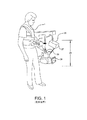
図1は、ステディカム(登録商標)として知られている従来技術の安定化カメラ支持システムを示しており、安定化カメラ支持システムは、カメラ28が吊り下げられた状態の「低モード」で展開されている。潜在的なレンズ高さの最大垂直範囲は線29によって示されている。
FIG. 1 shows a prior art stabilized camera support system known as Steadicam, which is deployed in a “low mode” with the
図2は、空間的に分離して支持するために用いられることが可能である、又は、本発明の実施形態の一部であり得る、典型的な従来技術の軽量「ベスト」1及び関節支持アーム2の正面図である。
FIG. 2 shows a typical prior art lightweight “vest” 1 and joint support that can be used to support spatially separate or may be part of an embodiment of the present invention. 3 is a front view of an
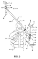
図3は、カメラ6の最大レンズ高さを得るために展開される本発明の例示の実施形態を示している。アーム2は、ベスト1に取り付けられてその動程の限界まで上昇している。アーム2は、マスタスレッド3とスレーブスレッド5との間で装置のバランス中心4bに配置されるポールジンバル4aによってバランスポール4に取り付けられている。
FIG. 3 shows an exemplary embodiment of the present invention that is deployed to obtain the maximum lens height of the
マスタスレッド3は、マスタスレッドジンバル3bでバランスポール4に取り付けられている。マスタスレッドジンバル3bは、バランスポール4と中心ポスト3aとの間で3つの度の角度分離を提供する。図3では、バランスポール4は、カメラ6を最大限に持ち上げるために張られている。スレーブスレッド5はスレーブジンバル5bでポール4に取り付けられている。スレーブスレッド5は、マスタジンバル3bでの位置及び角度移動を二重にするために(例えば図6に示される)サーボモータによって方向付けられる。サーボモータは、マスタスレッド3に配置されるセンサからの情報に基づく信号に応答する(例えば図5参照)。マスタスレッドのセンサからの信号は例えばサーボ増幅器及び/又はソフトウェアによって調節されてよい。オペレータは、マスタスレッド5に配置されるモニタ8上でカメラ6からの遠隔画像を見る。
The
ここで示される本発明の例示の実施形態ではサーボモータが例として用いられている。他のセンサ/モータの組み合わせが本発明の範囲内にある。好適には、センサ/モータの組み合わせは閉ループ制御システムである。多くの用途のために低振動及び低ノイズが望ましい。例えば約3000rpm〜5000rpmの高速がまた望ましい。本発明の例示の実施形態では、解決策は、1回転約1000パルス(pulse per revolution)〜1回転約10000パルスの範囲である。代替の実施形態では、ステッピングモータなどが用いられ、マスタスレッドの運動とスレーブスレッドの運動との間の遅延時間を減少させ得るものの、そうしたモータは、閉ループではなく、高いノイズ及び振動を有する傾向がある。 In the exemplary embodiment of the present invention shown here, a servo motor is used as an example. Other sensor / motor combinations are within the scope of the present invention. Preferably, the sensor / motor combination is a closed loop control system. Low vibration and low noise are desirable for many applications. For example, high speeds of about 3000 rpm to 5000 rpm are also desirable. In an exemplary embodiment of the invention, the solution ranges from about 1000 pulses per revolution to about 10,000 pulses per revolution. In an alternative embodiment, a stepping motor or the like may be used to reduce the delay time between master thread movement and slave thread movement, but such motors are not closed loop and tend to have high noise and vibration. is there.
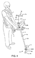
図4は、カメラ6の最小レンズ高さのために展開される本発明の例示の実施形態を示している。アーム2はその動程の下限に押し下げられており、バランスポール4は下方の角度に動かされている。スレーブスレッド5上のカメラ6は、マスタスレッド3の方向に基づいた方向に向けられている。本発明の特定の実施形態では、カメラ6はマスタスレッド3と同じ方向に向けられたままである。このことは、マスタジンバル3bとバランスポール4との間の時々刻々の角度、マスタスレッド3が再位置決めされる時に変化する他の空間的関係、を好適に連続的に検出して、スレーブジンバル5bの要素を駆動して、及び従って同期して再位置決めするために配置される例えばサーボモータ(図示せず)などのモータによってその角度(又は他の測定)を再び生成することによって実現される。
FIG. 4 shows an exemplary embodiment of the present invention deployed for the minimum lens height of the
マスタ及びスレッドの構成要素の間の相互接続部は機械的又は電気的であり得る。モータ及びセンサは、配線で接続されてよく、無線で接続されてよいことに留意されたい。機械的接続部は、タイロッド、プーリ、ギア、又は同様の装置を含み得る。第1地点の運動を第2地点の運動に置き換えるために、パンタグラフに用いられるような平行四辺形に基づいた方法で接続される機械的リンクが、本発明の実施形態での使用に適合し得る。このことは、第1地点から第2地点までの運動の増幅又は縮小、又は、1対1の対応の運動の増幅又は縮小を含み得る。 The interconnect between the master and thread components can be mechanical or electrical. Note that the motor and sensor may be connected by wires or may be connected wirelessly. The mechanical connection may include tie rods, pulleys, gears, or similar devices. A mechanical link connected in a parallelogram-based manner, such as that used in pantographs, to replace the first point movement with the second point movement may be adapted for use in embodiments of the present invention. . This may include amplification or reduction of motion from a first point to a second point, or amplification or reduction of a one-to-one corresponding motion.
図面は、装置のスレーブ端に配置されるカメラとマスタ端に配置されるモニタとを概して示している。本発明の例示の実施形態では、カメラは、同時撮影のために装置のスレーブ端及びマスタ端の両方に設置されている。 The drawing generally shows a camera located at the slave end of the device and a monitor located at the master end. In an exemplary embodiment of the invention, cameras are installed at both the slave and master ends of the device for simultaneous shooting.
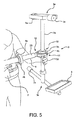
図5は、本発明の例示の実施形態に係るマスタスレッド3の拡大図を示す。ジンバル3bは、バランス中心3cのちょうど上方に配置されている。釣り合い重り機器3eは、上側機器7aとモニタ8を有する下側機器7bとから構成されている。釣り合い重り機器には、例えばカメラCCU(カメラ制御ユニット)及び関連したバッテリ、マイクロ波伝送装置、レンズ制御増幅器などの様々な他の構成要素が含まれ得る。非機能性質量が重りとして用いられてもよい。オペレータの手は、位置3d(好適にはバランス中心3cにできる限り近い位置)でマスタスレッド3の姿勢を制御する。センサ10、11及び12は、バランスポスト4に対して中心ポスト3aの(相互に垂直な3つの軸線の)角度位置を検出する。バランスポスト4は、その自身のバランス中心4bでジンバル4aによって支持されている。マスタスレッド3は、例えば、必ずしも(図4/図5に示されるように離れて装着される)カメラを有する必要がないことを除いては、すべての観点でステディカム(登録商標)のスレッドであり得る。マスタスレッド3は、中心ポストから選択可能な距離に質量を位置決めすることによって角度的に不活性の状態にされ、ジンバル3b及びアーム2によってオペレータの望まない運動から分離される。好適には、マスタスレッド3は、例えば補正装置のバランス調整によってほぼ水平に吊り下げるように調節されてわずかに底部を重くするようにバランスがとられ、例えば位置3dのオペレータの手によって任意の角度方向に方向付けられることが可能である。装置は、オペレータの手の最も軽い接触がマスタスレッド3を方向付けることができるように形成され得る。マスタスレッド3は、釣り合い重り機器7a及びモニタ8の上側及び下側セットを中心ポストから様々な距離に選択的に位置決めすることによって、パン、チルト及びロールのすべての3軸において不活性の状態にされる。センサ10、11及び12は、実質的に摩擦なしで好適に動作し、及び従って、角度安定性を低下させない。マスタスレッド3は、従って、オペレータの思いのままに狙いを定め得る安定的で角度的に機敏な基準プラットフォームを提供し、それによって、離れて位置決めされたスレーブスレッド5とスレーブスレッド5に取り付けられたカメラ6とを制御し得る。マスタスレッド3は、バランスポール4が持ち上げられたり旋回されたりした場合でさえもその角度の方向を維持し、及び従って、バランスポール4の旋回及び/又は持ち上げによって生じる角度効果を無効にするか又は減少させるために対応して「バックパン」して「バックチルト」するスレーブスレッド5及びカメラ6の角度の方向を維持する。
FIG. 5 shows an enlarged view of the
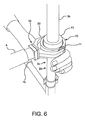
図6は、本発明の例示の実施形態に係るセンサ10、11及び12を示すマスタスレッド3のジンバル部分3bの拡大図である。この実施形態では、センサ10、11及び12は、互いに相互に垂直に位置決めされており、各々は、相互に垂直な3つの方向のいずれか1つの回転を検出する。方向は、縦方向の中心ポスト軸線回りの例えばパン、パンの軸線に垂直なマスタスレッドジンバル軸線回りのピッチ、並びに、パンの軸線及びピッチの軸線に相互に垂直なバランスポールの長手方向軸線回りのロールである。他のセンサの位置決め及び自由度が本発明の範囲内に含まれる。中心ポスト3a及びポスト4の間の時々刻々の角度は、3つのセンサ10、11及び12によって検出される3つの相互に垂直な構成要素角度に分解される。センサ10は、中心ポスト3aとジンバル3のパンベアリングレースの平面との間の角度を記録する。センサ11は、ヨーク30の平面と中心ポスト3aとの間の角度を記録する。センサ12は、ヨーク30の平面とポスト4との間の角度を記録する。これらの検出された角度はその後、類似のサーボモータに送られて、スレーブスレッド5上のカメラが同期して狙いを定められるように再び生成される。スレーブスレッドジンバル5bと釣り合い重り機器5c(例えば図4に示される)とは、サーボモータ10、11及び12から生じる再位置決めの間、スレーブスレッド5及びカメラ6を安定化させたまま維持するように働く。
FIG. 6 is an enlarged view of the
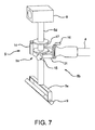
図7は、本発明の例示の実施形態に係るカメラ6及び補助モニタ9と、3つのサーボモータ14、15及び16の位置を示すスレーブスレッド5との拡大図である。マスタスレッド又はその構成要素の運動に基づいて生成される位置決めデータに応答して、モータ14、15及び16は、マスタスレッドの運動に対応してスレーブ中心ポスト5d及びバランスポール4の間の角度の関係を連続的に制御する。その結果、マスタスレッドと常に同じ方向にカメラ6の狙いを定めることができ、オペレータは、マスタスレッドを直感的にパン、チルト及びロールさせることができ、かつ、マスタモニタ又はスレーブモニタ9のいずれかによって、オペレータの意図したカメラの動きが実現されたことを見ることができる。本発明の代替の実施形態では、スレーブスレッドでの運動は、増幅され、又は減少させられ、又は、マスタスレッドでの運動と1対1の対応を有する。スレーブスレッド及びマスタスレッドでの運動の間の関係は、比例であるか、反比例であってよく、又は、センサ/モータシステムの構成、及び/又は、支持システムの構成によって決定されるような他の関係を有してもよい。
FIG. 7 is an enlarged view of the
図7は、ポスト4とスレーブジンバルヨーク31の平面との間の軸線方向の角度を制御するモータ16を示している。モータ15は、ヨーク31の平面とスレーブジンバル5上のパンベアリングレースとの間の角度を制御する。モータ14は、中心ポスト5dと前述のスレーブベアリングレースとの間の角度を制御する。好適な実施形態では、ジンバル5bは、スレーブスレッドのバランス中心5aに位置決めされてクランプ17によってポスト5dに対して所定の位置にロックされ、その結果、スレーブスレッド5のバランスは、中立的であり、ポスト5dに対してバランスポスト4の角度に何ら影響しない。
FIG. 7 shows the
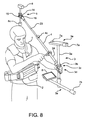
図8は、オペレータの背後で上方に真っ直ぐ撮影することに関する位置及び方向に展開される本発明の例示の実施形態を示す。マスタスレッド3は後方に狙いを定められる。バランスポール4は上方かつ後方にチルトされる。オペレータは、マスタスレッドモニタ8上でカメラ6からの対応して方向付けられた遠隔画像を見る。こうした極端なチルト角は、釣り合い重り機器3eの一部とポール4との衝突の危険性を増大させることがあるものの、これらの潜在的な干渉は、所望のショットを得るために適切な体の位置及びポストの角度を選択することによって容易に回避される。オペレータは歩行中であるので、潜在的に機器の一部によって遮られるカメラ角度は、わずかに異なる体の位置を用いることによってたいてい避けることが可能である。
FIG. 8 illustrates an exemplary embodiment of the present invention deployed in a position and orientation with respect to shooting straight up behind the operator. The
図9は、マスタスレッド3及びスレーブスレッド5の間で展開される特別に長いバランスポール4を備える特別に拡張した本発明の例示の実施形態を示す。拡張バランスポール4は2つの部分23、24を有する。この構成では、ポール部分23は、バランス中心3cのジンバル3bからスレーブスレッド5まで延びており、ポール部分24よりも長い。より短い部分24はジンバル3bからマスタスレッド3まで延びる。図示されるように、ジンバル3bからスレーブスレッド5までの距離とジンバル3bからマスタスレッド3までの距離との比はおおよそ6:1で示されている。こうして、(無視してもよいバランスポールの重量を引いた)スレッド3及び5の間の重量比は、逆関数であって同じ6:1の比でなければならない。このことは、マスタスレッドジンバル3bの上方及び下方に必要とされるような釣り合い重りを追加したり取り外したりして、アーム2の持ち上げ力を調節することによって実現される。ステイ36と関連した覆い37との1以上の任意選択的なセットが、バランスポール4の撓みを減少させるか又は除去し、それによって、その円柱構造を実質的に維持して、潜在的な跳ね上がりを減少させるとともにその長手方向軸線回りのそのバランスを維持する。バランスポールを支持する又は補強する他の装置が、ステイ及び覆いとは別個に又は関連して用いられてもよい。例えば特定の合成物又は合金などの材料の適切な選択がそうした装置への要求を除去し又は減少させる。しかしながら、本発明の一部の実施形態では、バランスポールは円柱でなくてもよく、いくらか湾曲していてよいことに留意されたい。
FIG. 9 shows an exemplary embodiment of the present invention with a specially extended balance pole 4 that is deployed between the
図10は、本発明の代替の実施形態を示しており、マスタスレッド及びスレーブスレッドのジンバルヨーク30及び31の両方が、回転可能な「動的」バランスポール18への堅い接続部19及び20を有しており、こうして機械的手段によって軸線方向に同期したまま維持される。この実施形態は、ハンドグリップの移動とポール18の移動とを相互に分離するための環状ベアリング21a又は他の機構を有するハンドグリップ21を有する。従って、ポスト18を旋回させ及び/又は持ち上げるためにオペレータによって作用させられる力は、ポスト18並びにヨーク30及び31に角度的に伝達されず、及び従って、マスタスレッド3は、ベアリング21a又は他の分離した機構からのわずかな軸線方向の摩擦のみを除いて、実質的に角度的に分離されたままである。本発明のこの例示の実施形態は、1つは機械的手段によってかつ2つは電気的手段によって3つの軸線すべてにおいて相互接続されるために、マスタスレッドジンバルに2つのみのセンサと、スレーブジンバルに2つの対応するモータと、を必要とする。動的バランスポール18は、図9に示される覆い及びステイの1以上のセットを任意選択的に有してもよい。ステイ及び覆いとは代替的に又はステイ及び覆いに加えて、バランス重量クランプ38は、動的バランスポール18に対して外側に調節可能な重り41を位置決めすることによって、その長手方向軸線回りにバランスポール18のバランスをとるように働き得る。こうして、バランスポール18に接続されるクランプカラー39は、ねじ付きロッド40が、釣り合い重りを必要とする方向に向けられるように回転させられる。クランプカラー39はその後、もはやバランスポール18回りに回転することができないようにバランスポール18に固定される。調節可能な重り41は、その後、バランスポール18が軸線方向にバランスがとられるまでねじ付きロッド上で内側又は外側に回される。覆い及びステイ並びに/又はバランス重りクランプ38のいずれかの使用は、バランスポール18のバランスが、それらの重心回りのマスタスレッド3又はスレーブスレッド5のいずれかの明確な個々のバランスに作用しないことを確保することができる。
FIG. 10 shows an alternative embodiment of the present invention in which both the master and slave thread gimbals yokes 30 and 31 have
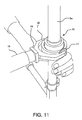
図11は、堅い軸線接続部19による動的ポスト18へのヨーク30の機械的取付を示すマスタスレッドジンバル3aの拡大図を示す。2つの残りの回転センサ10及び11は、スレーブスレッド上のそれらの他方に対してそれらのそれぞれの軸線のサーボ制御接続部を与える。
FIG. 11 shows an enlarged view of the
図12は、堅い軸線方向接続部20によって動的バランスポスト18に取り付けられる図10のスレーブスレッドヨーク31の拡大図を示す。モータ14及び15は、例えばサーボ増幅器から電気的衝撃を受けて、マスタスレッドで導き出されたセンサ入力に応じてそれらの対応の軸線を同期させ、その結果、カメラ6が、マスタスレッドと同様に3つのすべての軸線で同一の角度姿勢を維持する。
12 shows an enlarged view of the
図13は、図10に示される本発明の例示の実施形態の動的バランスポール18を持ち上げて旋回させるための環状で軸線方向に分離されたハンドグリップ21の拡大図を示しており、機械的接続部が3つのサーボ制御接続部の1つに代替されている。環状ベアリング21aは、ハンドグリップの強い旋回及び/又は持ち上げ運動がポール18上に角度を形成する作用を防止する。
FIG. 13 shows an enlarged view of an annular, axially separated
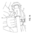
図14は、環状で軸線方向に分離されたハンドグリップ21の他の例示の実施形態を示しており、ハンドグリップ22は、ハンドグリップ21の時々刻々の角度を適合させる彼のハンドグリップ位置を歪ませることなく動的バランスポール18を持ち上げて旋回させることが必要な運動及び力をより快適にオペレータが作り出すことができるようにハンドグリップ21からオフセットしており、かつ、ハンドグリップ21に調節可能に堅く接続されている。この実施形態はまた、環状ベアリング21a又は他の適切な機構によってポール18からグリップ21の環状で軸線方向の分離を提供する。
FIG. 14 shows another exemplary embodiment of a
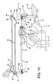
図15は、マスタスレッド34及びスレーブスレッド35の他の堅く接続された軽量の実施形態を示しており、第2回転軸線がタイロッド32によって堅く相互接続されるので、マスタスレッド34及びスレーブスレッド35のいずれもそれぞれのジンバル3b及び5bの上方又は下方に釣り合い重りを必要としない。他の接続装置、例えばプーリ及びベルト又は相互接続タイワイヤなどが用いられてもよい。従って、スレーブスレッド35はジンバル5bの上方にカメラ6のみを支えている。マスタスレッド34はジンバル3bの上方に釣り合い重りを有していない。図12に示される実施形態のように、バランスポール4並びにマスタ及びスレーブジンバルヨーク30及び31が、スレーブスレッド35に対してマスタスレッド34の1つの回転軸線に堅い相互接続部を有している。タイロッド32は、ポール18のスレーブスレッド端及びマスタスレッド端のそれぞれで旋回ヨーク33a、33bに取り付けられている。タイロッド32及びヨーク33a、33bによるマスタスレッド端及びスレーブスレッド端の間の堅い接続部は、スレーブスレッド35に対してマスタスレッド34の旋回角を伝達することを容易にする。タイロッド35は、例えば運動の極端なピッチ角で生じるタイロッド32とオペレータの手との間の干渉を緩和するためのタイロッド手起伏屈曲部32aを任意選択的に備えてよい。これは第2回転軸線を連結し、その結果、マスタスレッド釣り合い重り7b及び8は、単一の仮想ジンバルによって吊り下げられる単一の仮想中心ポスト上で互いに上方及び下方に直接的に装着される場合にバランスカメラ6のバランスをとるように働き得る。その結果は、ハンドグリップ部分3dでオペレータによるマスタスレッド34の角度制御が、スレーブスレッド35上でカメラ6の実質的に同一の回転を生成することである。スレッド34及び35のいずれも、ほぼ中立的な角度バランスのために独立して釣り合いがとられないものの、スレッド34、35、バランスポール4及び旋回ヨーク30、31及び33の相互接続された組み合わせが、極めて高いレンズ高さ及び極めて低いレンズ高さを実現するため、図示されるように水平方向に延びるため、さらなる自由度を用いれば、あたかも例えばステディカム(登録商標)などの従来型の単一スレッドの支持装置を作動させる場合に同一の感触を提供する。マスタスレッド及びスレーブスレッド34、35のそれぞれのパン軸線における同期は、センサ/モータ手段のいずれかによって、又は、対のタイロッド及びクランク(図16参照)、及び/又は、例えばセクタギアなどのベルト及びギアによって実現される。
FIG. 15 shows another rigidly connected lightweight embodiment of the master thread 34 and the
図16は、本発明の例示の実施形態に係るマスタスレッド及びスレーブスレッドの間のピッチ運動及び制限されたパン運動の両方を複数部品のタイロッドが同期させる電子サーボモータ接続部を必ずしも必要としない支持システムを示している。タイロッド42は、タイロッド自在継ぎ手43同士の間で延び、及び従って、タイロッドストラット46の先端に取り付けられるものの、タイロッド自在継ぎ手43によって2つの軸線で角度的に切断される。タイロッド42は、従って、マスタ及びスレーブスレッドの間の制限されたパン運動を同期させることができる。タイロッド起伏屈曲部44は、タイロッド42と拡張されたマスタ及びスレーブ中心ポスト45a、45bとの間の早期の干渉を防止することによってパン運動の角度範囲を増大させることができる。
FIG. 16 illustrates a support that does not necessarily require an electronic servo motor connection for a multi-part tie rod to synchronize both pitch movement and limited panning movement between the master and slave threads according to an exemplary embodiment of the present invention. Shows the system. The
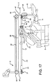
図17は、電子サーボモータ接続部を必ずしも必要としない他の支持構造を示しており、歯付きギア及びベルトが、本発明の例示の実施形態に係るマスタ及びスレーブスレッドの間のピッチ運動及びパン運動の両方を同期させるためにタイロッドと連動して作動する。歯付きギア48及びベルト49は、マスタスレッド3及びスレーブスレッド5の間のピッチ運動及びパン運動の両方を同期させるためにタイロッド32と連動して作動する。ベベルギアセット50ab(図18に示される)は、ベルト49及びギアホイール48を介してマスタスレッド3に作動させるパン運動を伝達するために横切る。
FIG. 17 shows another support structure that does not necessarily require an electronic servo motor connection, in which the toothed gear and belt are pitched and panned between the master and slave threads according to an exemplary embodiment of the present invention. Operates in conjunction with tie rods to synchronize both movements.
図18は、本発明の例示の実施形態に係るパン運動の同期を有効にするためにギアベルト及びベベルギアによってマスタスレッド及びスレーブスレッドの間の機械的な相互接続部を示す、図17の例示の実施形態のさらなる詳細を提供する。マスタスレッド3及びスレーブスレッド5の間の機械的な相互接続部のスレーブ端は、マスタスレッド3に分与されるパン運動をスレーブスレッド中心ポスト5dに伝達して同期させるパン制御ギアベルト49及びベベルギアセット50a及び50bを有している。スレーブスレッドのタイロッドヨーク(タイロッド32の端部回りに配置される)は拡張外側レースチューブ47(スレーブ中心ポスト5dの一部回りに配置される)に旋回可能に取り付けられ、タイロッド32によって、スレーブスレッド3及びマスタスレッド5の間のピッチ角も同期させる。
FIG. 18 illustrates the example implementation of FIG. 17 showing mechanical interconnections between the master and slave sleds by gear belts and bevel gears to enable pan motion synchronization according to an example embodiment of the present invention. Provide further details of the form. The slave end of the mechanical interconnection between the
図19は、本発明の例示の実施形態に係るバランスポール内に配置される同期構成要素を有する支持システムを概略的に示している。平行四辺形のテンションケーブル51a、bは、相互にほぼ平行にバランスポールを通って長手方向に延びている。これらは、マスタ中心ポール3aの運動がスレーブ中心ポスト5dで再現されるように、スレーブ及びマスタ支持部分の各々にヨーク52によって旋回可能に接続されている。パン軸線無端ベルト53は、パン軸線メイン駆動ギア55同士の間で延びてベルトアイドラギア54によってギア55上に案内される。ベルト53は3Dの歯付きベルトであることが好ましい。ワイヤ51及びベルト53のテンションは、バランスポール4の非圧縮性によって維持されており、バランスポール4は、ヨーク30によってマスタジンバル3bに取り付けられており、ヨーク31によってスレーブジンバル5bに取り付けられている。図表の明確性のために、図19にはこれらのいずれも図示されていないことに留意されたい。
FIG. 19 schematically illustrates a support system having a synchronization component disposed within a balance pole according to an exemplary embodiment of the present invention. The parallelogram tension cables 51a and 51b extend in the longitudinal direction through the balance pole substantially parallel to each other. These are pivotally connected to each of the slave and master support portions by a
本発明はまた、ここで説明される装置を使用する方法及び製造する方法を有している。 The present invention also includes methods of using and manufacturing the apparatus described herein.
各々が要素の異なる組み合わせを有する本発明の様々な実施形態が説明されてきた。本発明は、開示される特定の実施形態に限定されず、開示される要素の異なる組み合わせを有してよい。 Various embodiments of the invention have been described, each having a different combination of elements. The invention is not limited to the specific embodiments disclosed, but may have different combinations of the disclosed elements.
以下の特性の一部又はすべてが本発明の実施形態中にあってよい。
・任意の方向にオペレータから距離を置いて拡張されることが可能な軽量カメラのための簡略化した安価で小型の体支持型装着体又は車両支持型装着体であって、過度の労作を必要とせずに、拡張されたカメラに対して直感的で正確な局所的な3軸の角度制御によって「床から天井まで」レンズ高さを到達させることができる、軽量カメラのための簡略化した安価で小型の体支持型装着体又は車両支持型装着体。
・オペレータの位置からの横方向及び垂直方向の大きな変位に加えて、カメラの自由で直感的な角度制御を好適に有する安定化した撮影がなされ得るような、拡張された適用範囲及び角度機敏性。
・低モードブラケット、低モード変更部を排除した状態の体装着型カメラ安定化装置における連続的な垂直運動範囲。
・動作にあたってほとんど扱いにくくない装置を提供するため、「パン」軸線における不変の角度慣性に対して不釣り合いに大きくなる「チルト」軸線における角度慣性を有しないで、高いレンズ高さと、「低モード」において極めて低いレンズ高さと、を容易にするために伸長されることが可能であって、安定化されたままに加えて角度的に機敏なままである複数部分の入れ子式ポスト。
・カメラの水平姿勢を保持する高価で、水平検出の、ジャイロ振り子の統合コンピュータを必要としない、体装着型「ロールケージ」カメラ安定化装置の機能性及び角度機敏性における構造的に単純で電子的に複雑でない改善。
・長いスレッド中心ポストを持ち上げずに又は旋回させずに、離れて位置決めされたカメラヘッドの3軸の角度制御。
・本質的に「バックパン」しないぎこちなくて非直感的な「ジョイスティック」によって制御されることに代えて、直感的な正確性によって遠隔でパンされてチルトされる(及びロールされる)ことが可能なように、従来型のポール装着型カメラ支持体に比べて改善された角度機敏性。
・強烈な動的運動中でさえ水平の安定的な撮影を提供することができるとともに正確なオペレータの制御をさらに容易にすることができる、従来型のポール装着型カメラ支持体に比べて改善された角度安定性。
・自動的に「バックパン」(ポールが水平に旋回)して、又は垂直方向に「ブーム」して、カメラの角度姿勢が対応して変化せず、及び従って、所定の距離の物体に常に正確に「狙いを定める」ことがはるかに容易であるように、従来型の拡張ポール装着型カメラ支持体に比べて改善された角度制御。
・ショットの範囲内でその自身の局所的な支持構造を見なくても360°以上にわたって選択的にパン及びチルトすることができる「ポール装着型」カメラ。
・例えば1ポンド(0.4536kg)未満の重量のものであって、より大きくてより重い構造の角度慣性によってもなお安定化され得る、極めて軽量なカメラチップ/レンズの組み合わせのための支持システム。
・極めて低い及び高いレンズ位置を提供するものの、それらのショットを実現するために体の伸展労作を必要としないカメラ支持作動システム。
・介在して拡張されるバランスポールの先端にそれぞれ装着される取り付けられた軽量カメラを有しており、(任意選択的にはカメラを有しない)マスタスレッドの時々刻々の角度姿勢と小型のスレーブスレッドの時々刻々の角度姿勢との間の1対1の「マスタ/スレーブ」の関係をサーボ制御することに適合するものの完全に分離された慣性安定性を有する支持システム。
・安定的で反復可能であって、極めて高い/低い持ち上げ又は横方向の延在部でさらなる角度慣性を追加しない手段による軽量のビデオカメラの角度及び空間の遠隔制御の容易化。
・思いのままに「床から天井まで」レンズを持ち上げて、マスタスレッドに何ら角度の乱れを生じさせることなく水平方向にレンズを旋回させることを可能にする連続的な「ブーム」範囲(動的な垂直運動の範囲)。
・バランスポールのより長くて軽い端部に対するその角度関係が、ポールのより短くて重い端部に対するマスタスレッドの角度関係を連続的に模倣するように、スレーブスレッドの中心ポストとそれに関連したカメラとに対してその他端にほぼ1対1で再び生成される、取り付けられたバランスポールに対するマスタスレッド中心ポストの時々刻々の動的な3軸関係。
・マスタスレッド上に従来のように位置決めされたモニタを介して、スレーブスレッド上のカメラによって生成される画像の第1視野を見ること。
・スレーブスレッドのための釣り合い重りとして機能し、かつ、オペレータの注意がスレーブスレッドの近位で任意の障害物に集中しなければならない時に画像を見るための方法として機能する、追加のモニタによって第2視野を見ること。
・小さな開口を貫通することが可能であるものの局所的に独立したパン/チルト/ロール能力を保つことが可能であり、また、車両内で隔離されたマスタスレッドの安定化された質量に吹き付ける任意の風を伝達することなく、移動する車両内からスリップストリーム内に移動することが可能な小さな小型カメラヘッド。
・1つはマスタスレッド上にあり、任意選択的により小さい1つは拡張バランスポールの遠端でスレーブスレッド上にあり、その結果、後者の角度方向は前者の角度方向に対して従属装置として作動させられ、オペレータは例えばシーンのワイド撮影及びクローズアップ撮影を同時に供給することができる2つのカメラの同時制御。
・特別に長いバランスポールを持ち上げて旋回させる時に、カメラが非常に拡張されて、歩行中のオペレータから20フィート(609.6cm)以上離れても安定的で直感的に制御され、一貫して狙いを定めるために自動的に「バックパン」及び「バックチルト」されることが可能なように、軽量のポール部分の追加、又は、「スーパーポスト」入れ子式部分の追加、又は、動的に伸縮する部分の追加のためのモジュール構成。
・スレーブ端のカメラの質量を局所的に釣り合わせることを必要とせずに、より重いカメラの使用を容易にするバランスポール上に拡張されたスレーブカメラの遠隔制御。
Some or all of the following characteristics may be present in embodiments of the invention.
A simplified, inexpensive and compact body-supported or vehicle-supported attachment for a lightweight camera that can be extended away from the operator in any direction, requiring excessive effort Rather, simplified and inexpensive for lightweight cameras that can reach lens height “from floor to ceiling” with intuitive and accurate local 3-axis angle control for extended cameras A small body-supporting mounting body or a vehicle-supporting mounting body.
Extended coverage and angular agility so that in addition to large lateral and vertical displacements from the operator's position, stable imaging can be made that preferably has free and intuitive angle control of the camera .
・ Consecutive vertical motion range in body-mounted camera stabilization device without low mode bracket and low mode change part.
High lens height and “low mode” without angular inertia in the “tilt” axis, which increases disproportionately with the constant angular inertia in the “pan” axis to provide a device that is almost unwieldy in operation A multi-part telescopic post that can be stretched to facilitate extremely low lens height and remains angularly agile in addition to being stabilized.
Structurally simple and electronic in the functionality and angular agility of a body-mounted “roll cage” camera stabilizer that does not require an expensive, horizontal-detecting, gyro-pendulum integrated computer that maintains the horizontal posture of the camera Uncomplicated improvement.
• 3-axis angle control of the camera head positioned remotely without lifting or swiveling the long sled center post.
Can be remotely panned and tilted (and rolled) with intuitive accuracy instead of being controlled by awkward and non-intuitive “joystick” that essentially does not “back pan” As such, improved angular agility compared to conventional pole-mounted camera supports.
・ Improved compared to conventional pole-mounted camera support that can provide stable horizontal shooting even during intense dynamic motion and can further facilitate precise operator control Angle stability.
Automatically “back pan” (pole pivots horizontally) or “boom” vertically, the camera's angular attitude does not change correspondingly and therefore always on objects at a given distance Improved angle control compared to conventional extended pole mounted camera supports so that it is much easier to “target” accurately.
A “pole-mounted” camera that can selectively pan and tilt over 360 ° without having to see its own local support structure within the shot.
A support system for a very lightweight camera chip / lens combination, for example weighing less than 1 pound (0.4536 kg) and still being able to be stabilized by the angular inertia of larger and heavier structures.
A camera support actuation system that provides extremely low and high lens positions, but does not require body extension effort to achieve those shots.
Has a lightweight camera attached to each end of the balance pole, which is extended via an intermediary, with an optional angular attitude of the master thread (optionally without a camera) and a small slave A support system with fully isolated inertial stability that is compatible with servo-controlling the one-to-one “master / slave” relationship between the angular orientations of the sleds.
Facilitates remote control of the angle and space of a lightweight video camera by means that are stable and repeatable and do not add additional angular inertia with extremely high / low lift or lateral extensions.
• A continuous “boom” range (dynamic) that allows the lens to be lifted “floor-to-ceiling” at will and to turn the lens horizontally without causing any angular distortion in the master thread Range of vertical motion).
The central post of the slave thread and its associated camera so that its angular relationship to the longer and lighter end of the balance pole continuously mimics the angular relationship of the master thread to the shorter and heavier end of the pole. The dynamic 3-axis relationship of the master thread center post with respect to the attached balance pole, which is again generated approximately 1: 1 on the other end.
View the first field of view of the image produced by the camera on the slave sled through a monitor positioned conventionally on the master sled.
The additional monitor acts as a counterweight for the slave thread and serves as a way to view the image when the operator's attention must focus on any obstacles proximal to the slave thread. Look at two fields of view.
・ Although it is possible to penetrate small openings, it is possible to maintain locally independent pan / tilt / roll capability, and any spraying on the stabilized mass of the master thread isolated in the vehicle A small camera head that can move from a moving vehicle into a slipstream without transmitting the wind.
One is on the master thread and optionally one smaller is on the slave thread at the far end of the expansion balance pole, so that the latter angular direction acts as a slave to the former angular direction Simultaneous control of two cameras that can be operated and the operator can supply, for example, wide and close-up shots of the scene simultaneously.
-When lifting and turning a special long balance pole, the camera is greatly expanded and stable and intuitively controlled even if it is more than 20 feet (609.6 cm) away from the walking operator, aiming consistently Add a lightweight pole part, or add a “super post” telescopic part, or dynamically expand and contract so that it can be automatically “back panned” and “back tilted” to define Module configuration for adding additional parts.
Remote control of slave cameras extended on a balance pole that facilitates the use of heavier cameras without the need to locally balance the camera mass at the slave end.
本発明は、上の好適で単純化された実施形態に関して説明されたものの、様々な変更や修正が、安定して拡張可能で角度的に機敏なカメラ支持体の構成要素に対して本発明の範囲内でなされてもよいことが理解されよう。例えば、本発明はカメラを用いた使用に特に適用可能であるものの、本発明は他のタイプの機器又はツールを支持し、狙いを定め、位置決めし及び/又は安定化させるために用いられることが可能である。 Although the present invention has been described with reference to the preferred and simplified embodiments above, various changes and modifications may be made to the components of the camera support that are stably expandable and angularly agile. It will be understood that this may be done within the scope. For example, while the present invention is particularly applicable for use with cameras, the present invention may be used to support, aim, position and / or stabilize other types of equipment or tools. Is possible.
Claims (31)
第1ジンバル装置を有する前記バランスポールの前記第1端に接続されて、前記バランスポールの前記第1端周りにバランスがとられる1以上の第1構成要素質量と、
第2ジンバル装置を有する前記バランスポールの前記第2端に接続されて、前記バランスポールの前記第2端周りにバランスがとられる1以上の第2構成要素質量と、
前記バランスポールのバランス中心で前記バランスポールに取り付けられる第3ジンバルと、
前記第2ジンバルで前記第1ジンバルの運動を再現する機構と、を備える支持システム。 A balance pole having a first end and a second end;
One or more first component masses connected to the first end of the balance pole having a first gimbal device and balanced around the first end of the balance pole;
One or more second component masses connected to the second end of the balance pole having a second gimbal device and balanced around the second end of the balance pole;
A third gimbal attached to the balance pole at the balance center of the balance pole;
And a mechanism for reproducing the movement of the first gimbal by the second gimbal.
前記第1ジンバルの1以上の回転軸線回りの回転運動を検出する1以上のセンサと、
前記第2ジンバルに機能的に接続されて、前記第2ジンバルの1以上の回転軸線回りに回転運動を分与する1以上のモータと、を備えており、
1以上の前記モータは、1以上の前記センサから受信した信号に基づいて前記回転運動を分与して、前記第1ジンバルの回転軸線回りの運動を前記第2ジンバルの回転軸線回りに再現する、請求項1に記載の支持システム。 The mechanism that reproduces the movement is:
One or more sensors for detecting rotational movement of the first gimbal around one or more rotational axes;
One or more motors operably connected to the second gimbal and for distributing rotational movement about one or more rotational axes of the second gimbal;
The one or more motors distribute the rotational motion based on signals received from the one or more sensors, and reproduce the motion around the rotational axis of the first gimbal around the rotational axis of the second gimbal. The support system of claim 1.
前記バランスポールに接続されて前記バランスポール回りに自由に回転可能であるハンドグリップを備える請求項6に記載の支持システム。 The first and second gimbals each provide only two angular degrees of freedom, the angular degrees of freedom being the same angular degrees of freedom at each gimbal, and the support system further comprises:
The support system according to claim 6, further comprising a hand grip connected to the balance pole and freely rotatable about the balance pole.
前記第2構成要素質量は、機器の構成要素と、前記機器と釣り合う1以上の重りと、を有する請求項1に記載の支持システム。 The first component mass includes a component of the device and one or more weights that balance the device;
The support system according to claim 1, wherein the second component mass comprises a component of the device and one or more weights that balance the device.
前記第2構成要素質量は、第2機器構成要素を有しており、釣り合い重りを有していない請求項1に記載の支持システム。 The first component mass includes a first device component and one or more weights that balance the first device component;
The support system of claim 1, wherein the second component mass includes a second device component and does not have a counterweight.
ロッドにねじによって取り付けられる重りであって、前記バランスポールの長手方向軸線回りに前記バランスポールのバランスがとられるまで当該重りがねじロッド上で内側又は外側に回されることが可能なように前記ロッドが位置決めされる、重りを備える請求項24に記載の支持システム。 The balance clamp is
A weight attached to the rod by a screw so that the weight can be turned inward or outward on the threaded rod until the balance pole is balanced about the longitudinal axis of the balance pole The support system of claim 24, comprising a weight on which the rod is positioned.
第1中心ポストに旋回可能に取り付けられる第1タイストラットであって、第1端に第1自在継ぎ手を有するとともに第2端に第2自在継ぎ手を有する第1タイストラットと、
第2中心ポストに旋回可能に取り付けられる第2タイストラットであって、第1端に第1自在継ぎ手を有するとともに第2端に第2自在継ぎ手を有する第2タイストラットと、
前記第1ストラットの第1自在継ぎ手と前記第2ストラットの第1自在継ぎ手との間に長手方向に配置される第1タイロッドと、
前記第1タイロッドにほぼ平行であって、前記第1ストラットの第2自在継ぎ手と前記第2ストラットの第2自在継ぎ手との間に長手方向に配置される第2タイロッドと、を備える請求項1に記載の支持システム。 The mechanism for reproducing the movement of the first gimbal with the second gimbal is:
A first tie strut pivotably attached to a first central post, the first tie strut having a first universal joint at a first end and a second universal joint at a second end;
A second tie strut pivotably attached to a second central post, the second tie strut having a first universal joint at a first end and a second universal joint at a second end;
A first tie rod disposed longitudinally between a first universal joint of the first strut and a first universal joint of the second strut;
2. A second tie rod that is substantially parallel to the first tie rod and is disposed longitudinally between a second universal joint of the first strut and a second universal joint of the second strut. Support system as described in.
第1レースチューブから第2レースチューブまで延びるタイロッドであって、前記第1レースチューブは第1中心ポスト周りに配置され、前記第1中心ポストは前記第1ジンバルを通って配置され、前記第2レースチューブは第2中心ポスト周りに配置され、前記第2中心ポストは前記第2ジンバルを通って配置される、タイロッドを備え、
前記タイロッドは、第1端と、第2端と、各端にジンバルと、を有しており、
前記第1レースチューブは、当該第1レースチューブに取り付けられる第1歯付きギアを有しており、前記第2レースチューブは、当該第2レースチューブに取り付けられる第2歯付きギアを有しており、
前記第2ジンバルで前記第1ジンバルの運動を再現する機構は、
前記歯付きギアに対して機能的に適合するとともに前記歯付きギアに接続されるベルトを備える請求項1に記載の支持システム。 The mechanism for reproducing the movement of the first gimbal with the second gimbal is:
A tie rod extending from a first race tube to a second race tube, wherein the first race tube is disposed around a first center post, the first center post is disposed through the first gimbal, and the second A lace tube is disposed about a second center post, the second center post including a tie rod disposed through the second gimbal;
The tie rod has a first end, a second end, and a gimbal at each end;
The first race tube has a first toothed gear attached to the first race tube, and the second race tube has a second toothed gear attached to the second race tube. And
The mechanism for reproducing the movement of the first gimbal with the second gimbal is:
The support system of claim 1, comprising a belt that is functionally adapted to the toothed gear and connected to the toothed gear.
前記バランスポール内に配置されるケーブルを備える請求項1に記載の支持システム。 The mechanism for reproducing the movement of the first gimbal with the second gimbal is:
The support system of claim 1 comprising a cable disposed within the balance pole.
前記第1端で相互に前記第1構成要素質量のバランスをとる工程と、
前記第2端で相互に前記第2構成要素質量のバランスをとる工程と、
前記バランスポールの長手方向軸線回りで前記バランスポールのバランスをとる工程と、
前記バランスポール回りで前記第2質量に対して前記第1質量のバランスをとる工程と、
前記第1ジンバル装置を運動させて、前記構成要素質量のおおよそのバランスを維持しつつ前記第2ジンバル装置で前記運動を再現する工程と、
を備える機器のバランスをとって利用する方法。 Preparing a support system according to any one of claims 1 to 30;
Balancing the first component mass with each other at the first end;
Balancing the second component mass with each other at the second end;
Balancing the balance pole about the longitudinal axis of the balance pole;
Balancing the first mass with respect to the second mass around the balance pole;
Moving the first gimbal device to reproduce the movement with the second gimbal device while maintaining an approximate balance of the component masses;
To balance and use equipment with
Applications Claiming Priority (5)
| Application Number | Priority Date | Filing Date | Title |
|---|---|---|---|
| US11470908P | 2008-11-14 | 2008-11-14 | |
| US61/114,709 | 2008-11-14 | ||
| US11992108P | 2008-12-04 | 2008-12-04 | |
| US61/119,921 | 2008-12-04 | ||
| PCT/US2009/064351 WO2010056968A1 (en) | 2008-11-14 | 2009-11-13 | Extendable camera support and stabilization apparatus |
Publications (2)
| Publication Number | Publication Date |
|---|---|
| JP2012508904A true JP2012508904A (en) | 2012-04-12 |
| JP2012508904A5 JP2012508904A5 (en) | 2012-12-06 |
Family
ID=42170356
Family Applications (1)
| Application Number | Title | Priority Date | Filing Date |
|---|---|---|---|
| JP2011536504A Pending JP2012508904A (en) | 2008-11-14 | 2009-11-13 | Expandable camera support stabilizer |
Country Status (5)
| Country | Link |
|---|---|
| US (1) | US7931412B2 (en) |
| EP (1) | EP2353046A1 (en) |
| JP (1) | JP2012508904A (en) |
| CN (1) | CN102209934A (en) |
| WO (1) | WO2010056968A1 (en) |
Cited By (1)
| Publication number | Priority date | Publication date | Assignee | Title |
|---|---|---|---|---|
| KR20180053094A (en) * | 2016-11-11 | 2018-05-21 | 고려대학교 산학협력단 | Apparatus for collecting data for 3-d mapping |
Families Citing this family (35)
| Publication number | Priority date | Publication date | Assignee | Title |
|---|---|---|---|---|
| CN101420525A (en) * | 2007-10-26 | 2009-04-29 | 鸿富锦精密工业(深圳)有限公司 | Photographing apparatus and method |
| US8506180B2 (en) | 2008-11-14 | 2013-08-13 | Garrett W. Brown | Extendable camera support and stabilization apparatus |
| CN102209934A (en) | 2008-11-14 | 2011-10-05 | 加勒特·W·布朗 | Extendable camera support and stabilization apparatus |
| US8142083B2 (en) * | 2008-11-14 | 2012-03-27 | Brown Garrett W | Extendable camera support and stabilization apparatus |
| US8714744B2 (en) | 2009-10-07 | 2014-05-06 | Nigel J. Greaves | Gimbaled handle stabilizing controller assembly |
| US8585205B2 (en) | 2009-10-07 | 2013-11-19 | Nigel J. Greaves | Gimbaled handle stabilizing controller assembly |
| WO2011059526A1 (en) * | 2009-11-13 | 2011-05-19 | Brown Garrett W | Extendable camera support and stablization apparatus |
| CN102117075B (en) * | 2011-01-28 | 2014-04-09 | 西安电子科技大学 | Control method for position of photograph camera hauled by suspension cable |
| US8333520B1 (en) | 2011-03-24 | 2012-12-18 | CamMate Systems, Inc. | Systems and methods for detecting an imbalance of a camera crane |
| US8540438B1 (en) | 2011-03-24 | 2013-09-24 | CamMate Systems. Inc. | Systems and methods for positioning a camera crane |
| US9706172B1 (en) * | 2011-09-08 | 2017-07-11 | United Services Automobile Association (Usaa) | Roof inspection devices, methods, and systems |
| EP2589850A3 (en) * | 2011-11-03 | 2013-10-30 | BROWN, Garrett W. | Extendable camera support and stabilization apparatus |
| CN103777644A (en) * | 2012-10-24 | 2014-05-07 | 刘建新 | Low-altitude orbit intelligent robot image pick-up system and photographing method thereof |
| US9146005B1 (en) * | 2013-01-28 | 2015-09-29 | Benjamin Alexander Swanson | Portable media equipment support device with rotating action |
| CN103196014B (en) * | 2013-04-16 | 2015-04-08 | 张宝民 | Portable visual remotely-controlled omnibearing photographic arm |
| CN103322529B (en) * | 2013-06-05 | 2015-01-14 | 常熟市格威普气体设备有限公司 | Steering mechanism for cantilever frame |
| US9454064B2 (en) | 2014-02-04 | 2016-09-27 | Disney Enterprises, Inc. | Motorized monopod jib for cameras |
| JP2018502262A (en) | 2014-11-16 | 2018-01-25 | ギャレット・ダブリュー.・ブラウン | Tensile parallelogram arm |
| US9645475B2 (en) * | 2015-01-29 | 2017-05-09 | Spivo Inc. | Rotatable camera support |
| US9798221B2 (en) * | 2015-02-20 | 2017-10-24 | Disney Enterprises, Inc. | Motorized monopod jib for cameras |
| US9482386B2 (en) * | 2015-03-04 | 2016-11-01 | Daymen Us, Inc. | Extendable viewing system and kit allowing for assembly of extendable viewing system |
| US9769360B2 (en) | 2015-03-23 | 2017-09-19 | Harry Potter Investments Llc | Camera rig |
| DE102015117778A1 (en) * | 2015-04-30 | 2016-11-03 | Huf Hülsbeck & Fürst Gmbh & Co. Kg | Camera device for a motor vehicle |
| US20160371544A1 (en) * | 2015-06-22 | 2016-12-22 | Vivint Solar, Inc. | Photovoltaic measurement system |
| US9644946B1 (en) | 2015-07-09 | 2017-05-09 | Mark LeBlanc | System and method for photographic inspection and documentation of post-tensioned concrete tendon terminations |
| US10547773B2 (en) | 2016-10-28 | 2020-01-28 | Disney Enterprises, Inc. | User interface aspects for a motorized monopod jib for cameras |
| US10401713B2 (en) * | 2017-04-12 | 2019-09-03 | Adam Teichman | Mounted camera suspension and stabilization systems |
| US10583556B2 (en) | 2017-06-30 | 2020-03-10 | Disney Enterprises, Inc. | Motion stabilization on a motorized monopod jib |
| CN108183427B (en) * | 2018-01-04 | 2020-04-03 | 国家电网公司 | Transmission line foreign matter investigation robot device |
| USD911422S1 (en) * | 2019-03-22 | 2021-02-23 | Easyrig AB | Camera stabilizer |
| CN113438343A (en) * | 2019-07-04 | 2021-09-24 | 深圳叠品科技有限公司 | Connecting structure |
| US11720004B2 (en) * | 2021-04-05 | 2023-08-08 | Cinema Devices, Inc. | Camera gimbal and associated method of use |
| CN113188026B (en) * | 2021-04-30 | 2023-06-02 | 西安虚拟骑乘科技有限公司 | Multi-degree-of-freedom VR motion platform motion recording device/VR telescope |
| WO2022271681A1 (en) * | 2021-06-21 | 2022-12-29 | The Tiffen Company Llc | Actively stabilized payload support apparatus and methods |
| CN218626163U (en) * | 2022-11-18 | 2023-03-14 | 东莞市歌声美实业有限公司 | Take shooting support of counter weight |
Citations (4)
| Publication number | Priority date | Publication date | Assignee | Title |
|---|---|---|---|---|
| JPH05161037A (en) * | 1991-12-05 | 1993-06-25 | Biinoi:Kk | Crane for image pickup |
| JPH0868493A (en) * | 1994-08-29 | 1996-03-12 | Shiyoutoku Seisakusho:Kk | Camera crane |
| JPH09137892A (en) * | 1995-11-14 | 1997-05-27 | Biinoi:Kk | Article supporting device |
| US6752541B1 (en) * | 2003-02-28 | 2004-06-22 | John Dykyj | Camera jib |
Family Cites Families (81)
| Publication number | Priority date | Publication date | Assignee | Title |
|---|---|---|---|---|
| US494627A (en) * | 1893-04-04 | Non-conducting handle for tableware | ||
| US765980A (en) * | 1904-02-06 | 1904-07-26 | Adrien Mercier | Photographic-camera support. |
| US2156862A (en) * | 1935-03-20 | 1939-05-02 | Maugard Adolfo Best | Mount for cinema cameras, etc. |
| US2945428A (en) * | 1958-03-24 | 1960-07-19 | Howard K Dearborn | Camera stabilizer |
| US3756549A (en) * | 1972-01-14 | 1973-09-04 | Nuclear Data Ltd | Counterbalanced stand for camera |
| US3919902A (en) * | 1974-06-13 | 1975-11-18 | Global Marine Inc | Apparatus for suspending and spinning pipe |
| US4208028A (en) * | 1974-09-16 | 1980-06-17 | Garrett Brown | Support apparatus |
| US4017168A (en) * | 1974-09-16 | 1977-04-12 | Brown Garrett W | Equipment for use with hand held motion picture cameras |
| USRE32213E (en) * | 1974-09-16 | 1986-07-22 | Equipment for use with hand held motion picture cameras | |
| US3914540A (en) * | 1974-10-03 | 1975-10-21 | Magicam Inc | Optical node correcting circuit |
| US4092673A (en) * | 1976-05-18 | 1978-05-30 | Adams Jay W | Compatible composite image process |
| US4394075A (en) * | 1976-06-28 | 1983-07-19 | Garrett Brown | Support apparatus |
| US4158490A (en) * | 1976-11-11 | 1979-06-19 | Panavision, Incorporated | Body-mounted support device for motion picture camera |
| US4155100A (en) * | 1978-04-07 | 1979-05-15 | Hill Benjamin T Jr | Synchronously operational camera system |
| US4206983A (en) * | 1978-08-25 | 1980-06-10 | Continental Camera Systems, Inc. | Camera stabilizing body mount |
| US4270387A (en) * | 1979-04-30 | 1981-06-02 | The Singer Company | Drift compensated gyroscope |
| US4233634A (en) * | 1979-06-22 | 1980-11-11 | Adams Jay W | Video camera with adjustable mount and counterbalance |
| US4306714A (en) * | 1980-04-07 | 1981-12-22 | Loomis Joseph L | Iso-energetic ankle exerciser |
| JPS5723247A (en) | 1980-07-18 | 1982-02-06 | Fujitsu Ltd | Manufacture of bonding pad |
| US4474439A (en) * | 1982-01-26 | 1984-10-02 | Brown Garrett W | Camera support |
| WO1984002199A1 (en) * | 1982-12-01 | 1984-06-07 | Garrett W Brown | Improved suspension system for supporting and conveying equipment, such as a camera |
| US4625938A (en) * | 1983-10-24 | 1986-12-02 | Brown Garrett W | Suspension system for supporting and conveying equipment, such as a camera |
| DE3434386A1 (en) * | 1984-09-19 | 1986-03-27 | Sachtler GmbH Filmtechnische Geräte, 8046 Garching | FILM OR TELEVISION CAMERA TRIPOD |
| US4672436A (en) * | 1986-02-05 | 1987-06-09 | Louis Hawthorne | Integrated camcorder viewing and support system |
| GB8622879D0 (en) * | 1986-09-23 | 1986-10-29 | Dsam Ltd | Camera support systems |
| US4756655A (en) * | 1986-12-15 | 1988-07-12 | Jameson John W | Mechanical manipulator |
| FR2611855B1 (en) * | 1987-03-03 | 1989-07-13 | Spianti Dany | PORTABLE EQUIPMENT SUPPORT, ESPECIALLY CAMERA |
| US5243370A (en) * | 1988-08-30 | 1993-09-07 | Dan Slater | Camera stabilizer |
| US4946272A (en) * | 1988-09-22 | 1990-08-07 | Brown Garrett W | Stabilized equipment support, primarily for use with light-weight cameras |
| US5098182A (en) * | 1988-09-22 | 1992-03-24 | Brown Garrett W | Stabilized equipment support, primarily for use with light-weight cameras |
| US5229798A (en) * | 1988-09-22 | 1993-07-20 | Brown Garrett W | Stabilized equipment support, primarily for use with hand-held cameras |
| US5065249A (en) * | 1988-09-26 | 1991-11-12 | Vicon Industries, Inc. | Portable video camera/monitor support |
| US4989466A (en) * | 1989-08-02 | 1991-02-05 | Goodman Ronald C | Gyroscopically stabilized sensor positioning system |
| US6963792B1 (en) * | 1992-01-21 | 2005-11-08 | Sri International | Surgical method |
| US5435515A (en) * | 1992-09-15 | 1995-07-25 | Garrett W. Brown | Adustable, iso-elastic support apparatus |
| US5360196A (en) * | 1992-09-15 | 1994-11-01 | Garrett W. Brown | Adjustable, iso-elastic support apparatus |
| US5389987A (en) * | 1993-07-30 | 1995-02-14 | Corbeil; Gilles D. G. | Motion translation device for positioning cameras and other aimed instruments |
| US5490655A (en) * | 1993-09-16 | 1996-02-13 | Monger Mounts, Inc. | Video/data projector and monitor ceiling/wall mount |
| USD358832S (en) * | 1994-03-18 | 1995-05-30 | Garrett W. Brown | Camera support and stabilizing system |
| US5579071A (en) * | 1994-03-21 | 1996-11-26 | Garrett W. Brown | Camera stabilizing support |
| UA11298C2 (en) * | 1994-04-29 | 1996-12-25 | Анатолій Якимович Кокуш | jib operator's crane |
| FR2722893B1 (en) | 1994-07-22 | 1996-10-04 | Duc Alain | PORTABLE SHOOTING APPARATUS |
| WO1996015404A1 (en) | 1994-11-14 | 1996-05-23 | Thompson Michael William Fleet | Body-mounted stabilising apparatus for a camera |
| US5908181A (en) * | 1995-01-04 | 1999-06-01 | Valles-Navarro; Alfredo | Support for cameras |
| US5742859A (en) * | 1995-06-07 | 1998-04-21 | Acker; Heinz | Camera support and stabilizing device |
| US5786854A (en) * | 1995-11-21 | 1998-07-28 | Tree Top Systems, Inc. | Portable self-contained telescoping camera tower system for high angelimaging |
| WO1999050721A1 (en) * | 1997-09-19 | 1999-10-07 | Massachusetts Institute Of Technology | Robotic apparatus |
| US5752112A (en) * | 1996-11-06 | 1998-05-12 | George Paddock, Inc. | Mounting system for body mounted camera equipment |
| US5850579A (en) * | 1997-06-09 | 1998-12-15 | Addco, Inc. | Pan/tilt support with concentric drive shafts |
| US5963749A (en) * | 1998-02-09 | 1999-10-05 | Nicholson; Lynn | Self-leveling invertible camera stabilizer |
| US6293676B1 (en) * | 1998-02-17 | 2001-09-25 | Garrett W. Brown | Camera support including extendable post |
| US5940644A (en) * | 1998-04-22 | 1999-08-17 | Putora; Ivan | Balancing apparatus for stabilizing camera movement |
| US6468265B1 (en) * | 1998-11-20 | 2002-10-22 | Intuitive Surgical, Inc. | Performing cardiac surgery without cardioplegia |
| US7480041B2 (en) * | 1999-05-04 | 2009-01-20 | Envirosight Llc | Inspection system and method |
| US6377011B1 (en) * | 2000-01-26 | 2002-04-23 | Massachusetts Institute Of Technology | Force feedback user interface for minimally invasive surgical simulator and teleoperator and other similar apparatus |
| US6701081B1 (en) * | 2000-06-06 | 2004-03-02 | Air Controls, Inc. | Dual camera mount for stereo imaging |
| US6530702B2 (en) * | 2000-12-02 | 2003-03-11 | Thomas H. S. Harris | Operator supported remote camera positioning and control system |
| US6578967B1 (en) * | 2001-03-15 | 2003-06-17 | George Paddock Ii, Inc. | Mounting system for body mounted camera equipment and connector assemblies therefor |
| DE10145198C1 (en) * | 2001-09-13 | 2003-04-24 | Sachtler Gmbh & Co Kg | Gimbal hanger for a camera balance device |
| DE10145197B4 (en) * | 2001-09-13 | 2005-03-03 | Sachtler Gmbh & Co. Kg | Decoupled weight compensation for a camera balance device |
| DE10147602B4 (en) * | 2001-09-26 | 2004-11-04 | Horst Burbulla | Unlimited tilting camera crane |
| US6685148B2 (en) * | 2002-04-24 | 2004-02-03 | Adam Zadok | Support for hand held video camera |
| US7055368B2 (en) * | 2002-05-21 | 2006-06-06 | Kendro Laboratory Products, Inc. | Automatic calibration of an imbalance detector |
| US7000883B2 (en) * | 2003-01-17 | 2006-02-21 | The Insitu Group, Inc. | Method and apparatus for stabilizing payloads, including airborne cameras |
| US6923542B2 (en) * | 2003-03-11 | 2005-08-02 | Thomas H. S. Harris | Operator supported remote camera positioning and control system with longeron based beam |
| DE10319279A1 (en) * | 2003-04-29 | 2004-12-02 | Mela Industrieprodukte Gmbh | Lift arm system for image recorder e.g. camera, has each lift arm member formed of tubing material internally formed with bars |
| US7371028B2 (en) * | 2003-05-01 | 2008-05-13 | George Paddock Ii, Inc. | Post mounting system |
| US9002518B2 (en) * | 2003-06-30 | 2015-04-07 | Intuitive Surgical Operations, Inc. | Maximum torque driving of robotic surgical tools in robotic surgical systems |
| US7065888B2 (en) * | 2004-01-14 | 2006-06-27 | Aai Corporation | Gyroscopic system for boresighting equipment |
| US7654755B2 (en) * | 2005-04-12 | 2010-02-02 | The Tiffen Company Llc | Folding hinge |
| JP4834723B2 (en) * | 2005-04-15 | 2011-12-14 | ブラウン,ガレット,ダブリュー. | Folding and adjusting hinges for stabilizing support of equipment |
| CA2746546C (en) * | 2005-04-15 | 2014-03-04 | Garrett W. Brown | Equipoising support apparatus |
| US7642741B2 (en) * | 2005-04-27 | 2010-01-05 | Sidman Adam D | Handheld platform stabilization system employing distributed rotation sensors |
| US8342467B2 (en) * | 2005-10-04 | 2013-01-01 | Eric Ronald Stachowski | Apparatus for hand control, pressure amplification, and stabilization of medical and industrial devices |
| GB0619850D0 (en) * | 2006-10-06 | 2006-11-15 | Vitec Group Plc The | Camera control interface |
| US8792005B2 (en) * | 2006-11-29 | 2014-07-29 | Honeywell International Inc. | Method and system for automatically determining the camera field of view in a camera network |
| US20080187308A1 (en) * | 2007-02-06 | 2008-08-07 | Hannan Gerald J | Hand held self video device |
| EP2129957A4 (en) * | 2007-03-13 | 2011-04-27 | Garrett W Brown | Biased hinge for equipoising support equipment |
| WO2009033308A1 (en) | 2007-09-14 | 2009-03-19 | Marco Stoffel | Support for compact video camera |
| CN102165242A (en) * | 2008-09-30 | 2011-08-24 | 加勒特·W·布朗 | Biased hinge for equipoising support equipment |
| CN102209934A (en) | 2008-11-14 | 2011-10-05 | 加勒特·W·布朗 | Extendable camera support and stabilization apparatus |
-
2009
- 2009-11-13 CN CN2009801448258A patent/CN102209934A/en active Pending
- 2009-11-13 EP EP09826817A patent/EP2353046A1/en not_active Withdrawn
- 2009-11-13 JP JP2011536504A patent/JP2012508904A/en active Pending
- 2009-11-13 US US12/618,057 patent/US7931412B2/en active Active
- 2009-11-13 WO PCT/US2009/064351 patent/WO2010056968A1/en active Application Filing
Patent Citations (4)
| Publication number | Priority date | Publication date | Assignee | Title |
|---|---|---|---|---|
| JPH05161037A (en) * | 1991-12-05 | 1993-06-25 | Biinoi:Kk | Crane for image pickup |
| JPH0868493A (en) * | 1994-08-29 | 1996-03-12 | Shiyoutoku Seisakusho:Kk | Camera crane |
| JPH09137892A (en) * | 1995-11-14 | 1997-05-27 | Biinoi:Kk | Article supporting device |
| US6752541B1 (en) * | 2003-02-28 | 2004-06-22 | John Dykyj | Camera jib |
Cited By (2)
| Publication number | Priority date | Publication date | Assignee | Title |
|---|---|---|---|---|
| KR20180053094A (en) * | 2016-11-11 | 2018-05-21 | 고려대학교 산학협력단 | Apparatus for collecting data for 3-d mapping |
| KR101962755B1 (en) * | 2016-11-11 | 2019-03-28 | (주)티랩스 | Apparatus for collecting data for 3-d mapping |
Also Published As
| Publication number | Publication date |
|---|---|
| WO2010056968A1 (en) | 2010-05-20 |
| CN102209934A (en) | 2011-10-05 |
| US20100124414A1 (en) | 2010-05-20 |
| US7931412B2 (en) | 2011-04-26 |
| EP2353046A1 (en) | 2011-08-10 |
Similar Documents
| Publication | Publication Date | Title |
|---|---|---|
| JP2012508904A (en) | Expandable camera support stabilizer | |
| US8142083B2 (en) | Extendable camera support and stabilization apparatus | |
| US8506180B2 (en) | Extendable camera support and stabilization apparatus | |
| US8179078B2 (en) | Handheld or vehicle-mounted platform stabilization system | |
| US11140322B2 (en) | Stabilizing platform | |
| US7642741B2 (en) | Handheld platform stabilization system employing distributed rotation sensors | |
| AU573558B2 (en) | Suspension system for supporting and conveying a camera assembly | |
| EP2589850A2 (en) | Extendable camera support and stabilization apparatus | |
| US4625938A (en) | Suspension system for supporting and conveying equipment, such as a camera | |
| CA1082513A (en) | Steady camera support with expanded counterbalanced mounting | |
| WO2011059526A1 (en) | Extendable camera support and stablization apparatus | |
| US5974978A (en) | Stabilized lightweight equipment transport system | |
| US10551724B2 (en) | Motorized monopod jib for cameras | |
| US10921689B2 (en) | Enhanced camera positioner | |
| US20100264283A1 (en) | Support for compact video camera | |
| RU2705102C1 (en) | Method of filming and system for its implementation | |
| CA1218259A (en) | Improved suspension system for supporting and conveying equipment, such as a camera | |
| WO2006028390A1 (en) | Camera steadying apparatus | |
| Marietta | Camera Supports | |
| JPH04342376A (en) | Photographing auxiliary device for camera |
Legal Events
| Date | Code | Title | Description |
|---|---|---|---|
| A521 | Written amendment |
Free format text: JAPANESE INTERMEDIATE CODE: A523 Effective date: 20121019 |
|
| A621 | Written request for application examination |
Free format text: JAPANESE INTERMEDIATE CODE: A621 Effective date: 20121019 |
|
| A977 | Report on retrieval |
Free format text: JAPANESE INTERMEDIATE CODE: A971007 Effective date: 20131008 |
|
| A131 | Notification of reasons for refusal |
Free format text: JAPANESE INTERMEDIATE CODE: A131 Effective date: 20131015 |
|
| A521 | Written amendment |
Free format text: JAPANESE INTERMEDIATE CODE: A523 Effective date: 20140115 |
|
| A02 | Decision of refusal |
Free format text: JAPANESE INTERMEDIATE CODE: A02 Effective date: 20140304 |