JP2012508082A - Medical device, apparatus, system, and method - Google Patents
Medical device, apparatus, system, and method Download PDFInfo
- Publication number
- JP2012508082A JP2012508082A JP2011535785A JP2011535785A JP2012508082A JP 2012508082 A JP2012508082 A JP 2012508082A JP 2011535785 A JP2011535785 A JP 2011535785A JP 2011535785 A JP2011535785 A JP 2011535785A JP 2012508082 A JP2012508082 A JP 2012508082A
- Authority
- JP
- Japan
- Prior art keywords
- magnetic
- arm
- platform
- magnet
- magnetic field
- Prior art date
- Legal status (The legal status is an assumption and is not a legal conclusion. Google has not performed a legal analysis and makes no representation as to the accuracy of the status listed.)
- Pending
Links
Images


Classifications
-
- A—HUMAN NECESSITIES
- A61—MEDICAL OR VETERINARY SCIENCE; HYGIENE
- A61M—DEVICES FOR INTRODUCING MEDIA INTO, OR ONTO, THE BODY; DEVICES FOR TRANSDUCING BODY MEDIA OR FOR TAKING MEDIA FROM THE BODY; DEVICES FOR PRODUCING OR ENDING SLEEP OR STUPOR
- A61M25/00—Catheters; Hollow probes
- A61M25/01—Introducing, guiding, advancing, emplacing or holding catheters
- A61M25/0105—Steering means as part of the catheter or advancing means; Markers for positioning
- A61M25/0127—Magnetic means; Magnetic markers
-
- A—HUMAN NECESSITIES
- A61—MEDICAL OR VETERINARY SCIENCE; HYGIENE
- A61B—DIAGNOSIS; SURGERY; IDENTIFICATION
- A61B5/00—Measuring for diagnostic purposes; Identification of persons
- A61B5/06—Devices, other than using radiation, for detecting or locating foreign bodies ; determining position of probes within or on the body of the patient
- A61B5/061—Determining position of a probe within the body employing means separate from the probe, e.g. sensing internal probe position employing impedance electrodes on the surface of the body
- A61B5/062—Determining position of a probe within the body employing means separate from the probe, e.g. sensing internal probe position employing impedance electrodes on the surface of the body using magnetic field
-
- A—HUMAN NECESSITIES
- A61—MEDICAL OR VETERINARY SCIENCE; HYGIENE
- A61B—DIAGNOSIS; SURGERY; IDENTIFICATION
- A61B18/00—Surgical instruments, devices or methods for transferring non-mechanical forms of energy to or from the body
- A61B18/04—Surgical instruments, devices or methods for transferring non-mechanical forms of energy to or from the body by heating
- A61B18/12—Surgical instruments, devices or methods for transferring non-mechanical forms of energy to or from the body by heating by passing a current through the tissue to be heated, e.g. high-frequency current
- A61B18/14—Probes or electrodes therefor
-
- A—HUMAN NECESSITIES
- A61—MEDICAL OR VETERINARY SCIENCE; HYGIENE
- A61B—DIAGNOSIS; SURGERY; IDENTIFICATION
- A61B17/00—Surgical instruments, devices or methods, e.g. tourniquets
- A61B17/00234—Surgical instruments, devices or methods, e.g. tourniquets for minimally invasive surgery
- A61B2017/00238—Type of minimally invasive operation
- A61B2017/00283—Type of minimally invasive operation with a device releasably connected to an inner wall of the abdomen during surgery, e.g. an illumination source
-
- A—HUMAN NECESSITIES
- A61—MEDICAL OR VETERINARY SCIENCE; HYGIENE
- A61B—DIAGNOSIS; SURGERY; IDENTIFICATION
- A61B17/00—Surgical instruments, devices or methods, e.g. tourniquets
- A61B2017/00831—Material properties
- A61B2017/00876—Material properties magnetic
-
- A—HUMAN NECESSITIES
- A61—MEDICAL OR VETERINARY SCIENCE; HYGIENE
- A61B—DIAGNOSIS; SURGERY; IDENTIFICATION
- A61B18/00—Surgical instruments, devices or methods for transferring non-mechanical forms of energy to or from the body
- A61B2018/00571—Surgical instruments, devices or methods for transferring non-mechanical forms of energy to or from the body for achieving a particular surgical effect
- A61B2018/00595—Cauterization
Abstract
患者の体腔内に定置可能なデバイスとの電気的連絡を可能にするための装置およびシステム。患者の体腔内にデバイスを磁気的に定置するための装置およびシステム。医療デバイス。使用法。

Description
関連出願の相互参照
本出願は、どちらもその全内容が参照により本明細書に組み入れられる、2008年11月11日に提出された米国特許仮出願第61/113,495号、および2009年1月16日に提出された米国特許仮出願第61/145,469号に対する優先権を主張する。
CROSS-REFERENCE TO RELATED APPLICATIONS This application, both the entire contents of which are incorporated herein by reference, filed on November 11, 2008 the US Provisional Patent Application No. 61 / 113,495, and January 2009 16 Claims priority to US Provisional Application No. 61 / 145,469 filed on the day.
1.発明の分野
本発明は、一般的に医療デバイス、装置、システム、および方法に関し、より詳しくは、患者の体腔内で少なくとも部分的に医学的技法を行うための医療デバイス、装置、システム、および方法に関するが、これらに限定されない。
1. The present invention relates generally to medical devices, apparatus, systems, and methods, and more particularly to medical devices, apparatuses, systems, and methods for performing medical techniques at least partially within a body cavity of a patient. However, it is not limited to these.
2.関連技術の説明
説明するため、本発明の範囲を制限することなく、たとえば経管腔的内視鏡手術(NOTES)、単孔式腹腔鏡下手術(SILS)、およびシングルポート腹腔鏡手術(SLP)が含まれる腹腔鏡、経壁手術、および管腔内手術が含まれうる医学的技法(たとえば、外科的技法)に関する背景を記載する。
2. 2. Description of Related Art For purposes of explanation, without limiting the scope of the invention, for example, transluminal endoscopic surgery (NOTES), single-hole laparoscopic surgery (SILS), and single-port laparoscopic surgery (SLP) Background on medical techniques (eg, surgical techniques) that may include laparoscopic, transmural surgery, and endoluminal surgery.
直視下手術と比較して、腹腔鏡手術は、有意に少ない疼痛、より速やかな回復、およびより低い死亡率をもたらす。低侵襲性が同程度の外科的アプローチでありうるNOTESは、類似の結果を達成する可能性がある。しかし、眼と手が分離していること、二次元の視野、限られた自由度の機器、および要求される器用さの必要条件などの問題は、多くの腹腔鏡および内視鏡技法にとって難題を提起しうる。腹腔鏡の1つの限界は、各トロカール周囲の固定された作業空間でありうる。その結果、機器または腹腔鏡の位置の変化に適合させるために、たとえば可視性および効率を改善するために、多数のポートが用いられる可能性がある。しかし、追加の作業ポートを定置することは術後の疼痛に寄与する可能性があり、さらなる出血および隣接臓器の損傷などのリスクを増加させる。 Compared to direct surgery, laparoscopic surgery results in significantly less pain, faster recovery, and lower mortality. NOTES, a minimally invasive and comparable surgical approach, may achieve similar results. However, issues such as separate eyes and hands, two-dimensional fields of view, limited freedom of equipment, and required dexterity requirements are challenging for many laparoscopic and endoscopic techniques. Can be raised. One limitation of a laparoscope can be a fixed working space around each trocar. As a result, multiple ports may be used to adapt to changes in instrument or laparoscopic position, for example, to improve visibility and efficiency. However, placing additional working ports can contribute to post-surgical pain, increasing the risk of additional bleeding and adjacent organ damage.
以下の公表された特許出願には、本発明の医療デバイス、装置、システム、および方法を理解する上で有用である可能性がある情報が含まれ、その各々の全内容が参照により本明細書に組み入れられる:(1)2001年12月14日に提出されて、米国特許出願公開第2003/0114731号として公開された米国特許出願第10/024,636号(特許文献1);(2)2004年11月30日に提出されて、米国特許出願公開第2005/0165449号として公開された米国特許出願第10/999,396号(特許文献2);(3)2007年4月28日に提出されて、米国特許出願公開第2007/0255273号として公開された米国特許出願第11/741,731号(特許文献3);(4)2007年8月3日に提出されて、米国特許出願公開第2007/0276424号として公開された米国特許出願第11/833,729号(特許文献4);および(5)2007年2月27日に提出されて、米国特許出願公開第2008/0208220号として公開された米国特許出願第11/711,541号(特許文献5)。 The following published patent applications contain information that may be useful in understanding the medical devices, apparatus, systems, and methods of the present invention, the entire contents of each of which are hereby incorporated by reference. (1) United States Patent Application No. 10 / 024,636 filed December 14, 2001 and published as United States Patent Application Publication No. 2003/0114731 (Patent Document 1); (2) 2004 US Patent Application No. 10 / 999,396 filed November 30, published as US Patent Application Publication No. 2005/0165449 (Patent Document 2); (3) filed April 28, 2007, US Patent Application No. 11 / 741,731 (Patent Document 3) published as US Patent Application Publication No. 2007/0255273; (4) US Patent Application Publication No. 2007/0276424 filed on August 3, 2007 US patent application Ser. No. 11 / 833,729 (Patent Document 4); and (5) filed on Feb. 27, 2007, U.S. Patent Application No. 11 / 711,541 published as Permitted Application No. 2008/0208220 (Patent Document 5).
いくつかの態様は、患者の体腔内に定置可能なデバイスとの電気的連絡を可能にするための装置を含む。該デバイスは開口部と導電性部分とを有し得、該装置は、アンカー;および該アンカーに接続された導線を含み得、該アンカーと該導線の少なくとも一部とが、該患者の外部表面上の穿孔を通して該患者の体腔内および該デバイスの該開口部内に挿入可能であり(かつ/または挿入されるように構成され)、かつ、該導線と該デバイスの該導電性部分との間の電気的連絡を可能にしながら、該アンカーと該導線の一部とが該体腔から外れるのを阻止するように、該アンカーが該デバイスに接触できる(かつ/または接触するように構成される)。いくつかの態様において、前記導線は、導電性部分と、該導線の該導電性部分の周りに配置された絶縁材料層とを含む。いくつかの態様において、前記導線は、前記絶縁材料層の周りに配置された第二の導電性部分と、該導線の該第二の導電性部分の周りに配置された第二の絶縁材料層とをさらに含む。 Some aspects include an apparatus for enabling electrical communication with a device that can be placed in a body cavity of a patient. The device may have an opening and a conductive portion, and the apparatus may include an anchor; and a lead connected to the anchor, the anchor and at least a portion of the lead being an external surface of the patient Is insertable (and / or configured to be inserted) into the patient's body cavity and into the opening of the device through an upper perforation, and between the conductor and the conductive portion of the device The anchor can contact (and / or be configured to contact) the device to prevent the anchor and a portion of the lead from detaching from the body cavity while allowing electrical communication. In some embodiments, the lead includes a conductive portion and a layer of insulating material disposed around the conductive portion of the lead. In some embodiments, the conductor includes a second conductive portion disposed around the insulating material layer and a second insulating material layer disposed around the second conductive portion of the conductor. And further including.
いくつかの態様は、患者の体腔内に定置可能なデバイスとの電気的連絡を可能にするためのシステムを含む。該デバイスは、開口部と導電性部分とを有し得、かつ、該システムは、開口部と導電性部分とを有する、患者の体腔内に定置されるように構成されたデバイスと、該デバイスとの電気的連絡を可能にするための装置とを含み得る。該装置は、アンカー;および該アンカーに接続された導線を含み得、該アンカーと該導線の少なくとも一部とは、該患者の外部表面上の穿孔を通して該患者の体腔内および該デバイスの該開口部内に挿入可能であり、かつ、該導線と該デバイスの該導電性部分との間の電気的連絡を可能にしながら、該アンカーと該導線の一部とが該体腔から外れるのを阻止するように、該アンカーが該デバイスに接触できる。いくつかの態様において、前記デバイスは発光ダイオード(LED)を含み、かつ、前記導線と該デバイスとの間で電気的連絡が可能である場合に該導線と該LEDとの間で電気的連絡が可能である。 Some aspects include a system for enabling electrical communication with a device that can be placed in a body cavity of a patient. The device may have an opening and a conductive portion, and the system is configured to be placed in a body cavity of a patient having the opening and the conductive portion; and the device And a device for enabling electrical communication with the device. The apparatus may include an anchor; and a lead connected to the anchor, the anchor and at least a portion of the lead passing through a perforation on the patient's external surface and into the patient's body cavity and the opening of the device To prevent the anchor and a portion of the conductor from detaching from the body cavity while being insertable into the body and allowing electrical communication between the conductor and the conductive portion of the device. In addition, the anchor can contact the device. In some embodiments, the device includes a light emitting diode (LED), and electrical communication between the conductor and the LED is possible when electrical communication is possible between the conductor and the device. Is possible.
いくつかの態様において、前記アンカーは細長い金属材料片を含む。いくつかの態様において、前記アンカーは体積約1立方インチ未満に収まる。いくつかの態様において、前記アンカーの体積は長さ、幅、および高さによって定義され、該長さが約1インチ未満、該幅が約0.3インチ未満、該高さが約0.3インチ未満である。いくつかの態様において、前記デバイスの前記開口部は、該デバイス内に延びる凹部の少なくとも一部である。いくつかの態様において、前記デバイスの前記開口部は、該デバイスを通って延びる通路の少なくとも一部である。いくつかの態様において、前記デバイスの前記導電性部分は前記開口部に隣接する。いくつかの態様において、前記デバイスの前記導電性部分は前記開口部を実質的に取り囲んでいる。いくつかの態様において、前記導線は、第一の導電性部分と、該導線の該第一の導電性部分の周りに配置された絶縁材料層とを含む。いくつかの態様において、前記導線は、前記絶縁材料層の周りに配置された第二の導電性部分と、該導線の該第二の導電性部分の周りに配置された第二の絶縁材料層とをさらに含む。 In some embodiments, the anchor includes an elongated piece of metallic material. In some embodiments, the anchor fits in a volume less than about 1 cubic inch. In some embodiments, the anchor volume is defined by length, width, and height, wherein the length is less than about 1 inch, the width is less than about 0.3 inch, and the height is less than about 0.3 inch. . In some embodiments, the opening of the device is at least a portion of a recess that extends into the device. In some embodiments, the opening of the device is at least a portion of a passage extending through the device. In some embodiments, the conductive portion of the device is adjacent to the opening. In some embodiments, the conductive portion of the device substantially surrounds the opening. In some embodiments, the lead includes a first conductive portion and an insulating material layer disposed around the first conductive portion of the lead. In some embodiments, the conductor includes a second conductive portion disposed around the insulating material layer and a second insulating material layer disposed around the second conductive portion of the conductor. And further including.
いくつかの態様において、前記アンカーが前記デバイスに接触すると、該アンカーと前記導線のうち少なくとも一方が該デバイスの前記導電性部分に接触することができる。いくつかの態様において、前記アンカーが前記デバイスに接触すると、前記導線と該アンカーの両方が該デバイスの前記導電性部分に接触することができる。いくつかの態様において、前記アンカーが前記デバイスに接触すると、前記導線が該デバイスの前記導電性部分に接触することができる。いくつかの態様において、前記アンカーが前記デバイスに接触すると、該アンカーが該デバイスの前記導電性部分に接触することができる。いくつかの態様において、前記アンカーが前記デバイスに接触すると、該アンカーの一部だけが該デバイスの前記導電性部分に接触することができ、かつ、該デバイスの該導電性部分に接触できない該アンカーの一部が、該デバイスの該導電性部分から電気的に絶縁されている。 In some aspects, when the anchor contacts the device, at least one of the anchor and the conductor can contact the conductive portion of the device. In some embodiments, when the anchor contacts the device, both the conductor and the anchor can contact the conductive portion of the device. In some embodiments, when the anchor contacts the device, the lead can contact the conductive portion of the device. In some embodiments, when the anchor contacts the device, the anchor can contact the conductive portion of the device. In some embodiments, when the anchor contacts the device, only a portion of the anchor can contact the conductive portion of the device, and the anchor cannot contact the conductive portion of the device Is electrically isolated from the conductive portion of the device.
いくつかの態様は、患者の体腔内にデバイスを磁気的に定置するための装置を含む。該装置は、一次磁場源;および該一次磁場源の周りに配置された複数の周辺磁場源を含みかつ連結端を有する、磁気アセンブリと、該磁気アセンブリを支持するハウジングとを含み得、該ハウジングと該磁気アセンブリの体積は約64立方インチ未満である。いくつかの態様において、前記磁気アセンブリの前記一次磁場源はN極とS極とを有し;該磁気アセンブリの各周辺磁場源はN極とS極とを有し;かつ該周辺磁場源のN極が該一次磁場源のS極に隣接するように、各磁気アセンブリが構成される。 Some embodiments include an apparatus for magnetically placing the device in a body cavity of a patient. The apparatus can include a primary magnetic field source; and a magnetic assembly including a plurality of peripheral magnetic field sources disposed around the primary magnetic field source and having a coupling end, and a housing supporting the magnetic assembly, the housing And the volume of the magnetic assembly is less than about 64 cubic inches. In some embodiments, the primary magnetic field source of the magnetic assembly has N and S poles; each peripheral magnetic field source of the magnetic assembly has N and S poles; and Each magnetic assembly is configured such that the N pole is adjacent to the S pole of the primary magnetic field source.
本発明の装置のいくつかの態様は2つの前記磁気アセンブリを含み得、前記ハウジングは、該2つの磁気アセンブリを、その連結端が実質的に同一平面上にあるように、固定された関係で支持する。2つの磁場源を含むいくつかの態様において、各磁気アセンブリの前記一次磁場源はN極とS極とを有し、一方の磁気アセンブリの一次磁場源のS極は該磁気アセンブリの連結端に隣接し、他方の磁気アセンブリの一次磁場源のN極は該他方の磁気アセンブリの連結端に隣接する。いくつかの態様において、前記ハウジングおよび両方の前記磁気アセンブリの体積は約32立方インチ未満である。いくつかの態様において、前記ハウジングおよび両方の前記磁気アセンブリの体積は約22立方インチ未満である。 Some embodiments of the apparatus of the present invention may include two of the magnetic assemblies, wherein the housing places the two magnetic assemblies in a fixed relationship such that their coupling ends are substantially coplanar. To support. In some embodiments including two magnetic field sources, the primary magnetic field source of each magnetic assembly has a north pole and a south pole, and the primary magnetic field source south pole of one magnetic assembly is at the coupling end of the magnetic assembly. The north pole of the primary magnetic field source of the other magnetic assembly is adjacent to the connecting end of the other magnetic assembly. In some embodiments, the volume of the housing and both magnetic assemblies is less than about 32 cubic inches. In some embodiments, the volume of the housing and both of the magnetic assemblies is less than about 22 cubic inches.
いくつかの態様は、患者の体腔内にデバイスを磁気的に定置するための装置を含む。該装置は、各々が連結端を有する2つの磁場源;および該2つの磁場源の該連結端が互いに隣接するように、互いに固定された関係で該2つの磁場源を支持する、ハウジングを含み得、該装置は、約8平方インチ未満の連結面積を有する。いくつかの態様において、該2つの磁場源の少なくとも1つは、一次磁石;および該一次磁石の周りに配置された複数の周辺磁石を含む磁気アセンブリを含み得る。いくつかの態様において、前記装置の前記連結面積は約4平方インチ未満である。いくつかの態様において、各磁場源はN極とS極とを有し、一方の磁場源の連結端はS極を有し、他方の磁場源の連結端はN極を有する。いくつかの態様において、前記磁気アセンブリの前記一次磁石はN極とS極とを有し;該磁気アセンブリの各周辺磁石はN極とS極とを有し;かつ該周辺磁石のN極が該一次磁石のS極に隣接するように、該磁気アセンブリそれぞれが構成される。いくつかの態様において、前記2つの磁場源の各々は、一次磁石;および一次磁場源の周りに配置された複数の周辺磁石を含む磁気アセンブリを有する。各磁場源が磁気アセンブリを有するいくつかの態様において、各磁気アセンブリの前記一次磁石はN極とS極とを有し;各磁気アセンブリの各周辺磁石はN極とS極とを有し;かつ、該周辺磁石のN極が該一次磁石のS極に隣接するように各磁気アセンブリが構成される。 Some embodiments include an apparatus for magnetically placing the device in a body cavity of a patient. The apparatus includes two magnetic field sources each having a coupling end; and a housing that supports the two magnetic field sources in a fixed relationship with each other such that the coupling ends of the two magnetic field sources are adjacent to each other. And the device has a connected area of less than about 8 square inches. In some embodiments, at least one of the two magnetic field sources can include a magnetic assembly that includes a primary magnet; and a plurality of peripheral magnets disposed about the primary magnet. In some embodiments, the connecting area of the device is less than about 4 square inches. In some embodiments, each magnetic field source has a north pole and a south pole, the connection end of one magnetic field source has a south pole, and the connection end of the other magnetic field source has a north pole. In some embodiments, the primary magnet of the magnetic assembly has a north pole and a south pole; each peripheral magnet of the magnetic assembly has a north pole and a south pole; and the north pole of the peripheral magnet is Each of the magnetic assemblies is configured to be adjacent to the south pole of the primary magnet. In some embodiments, each of the two magnetic field sources has a magnetic assembly that includes a primary magnet; and a plurality of peripheral magnets disposed about the primary magnetic field source. In some embodiments where each magnetic field source has a magnetic assembly, the primary magnet of each magnetic assembly has N and S poles; each peripheral magnet of each magnetic assembly has N and S poles; Each magnetic assembly is configured such that the N pole of the peripheral magnet is adjacent to the S pole of the primary magnet.
いくつかの態様は、磁気吸引材料を含むデバイスと、装置が患者の体腔外にある場合に該体腔内で該デバイスを移動させるための該装置とを含む、システムを含み、磁気アセンブリは、該体腔外の該装置を移動させることによって該デバイスを該体腔内で移動させることができるように、該患者の体の外部表面を通して該デバイスの磁気吸引材料と磁気的に連結可能である。いくつかの態様において、該装置は、一次磁場源;および、該一次磁場源の周りに配置された複数の周辺磁場源を含みかつ連結端を有する、磁気アセンブリを含む。いくつかの態様において、前記デバイスの前記磁気吸引材料は磁石を含む。いくつかの態様において、前記装置は2つの前記磁気アセンブリを含む。いくつかの態様において、各磁気アセンブリの前記一次磁場源はN極とS極とを有し、一方の磁気アセンブリの一次磁場源のS極は該磁気アセンブリの連結端に隣接し、かつ他方の磁気アセンブリの一次磁場源のN極は該他方の磁気アセンブリの連結端に隣接する。いくつかの態様において、前記デバイスは連結面を有し、該デバイスの前記磁気吸引材料は、S極とN極を各々が有する2つの磁石を含み、一方の磁石のN極は該デバイスの該連結面に隣接し、かつ他方の磁石のS極は該デバイスの該連結面に隣接する。 Some aspects include a system that includes a device that includes a magnetic attraction material and the apparatus for moving the device within the body cavity when the apparatus is outside the body cavity of a patient, the magnetic assembly comprising: The device can be magnetically coupled with the magnetic attraction material of the device through an external surface of the patient's body so that the device can be moved within the body cavity by moving the device outside the body cavity. In some embodiments, the apparatus includes a magnetic assembly including a primary magnetic field source; and a plurality of peripheral magnetic field sources disposed about the primary magnetic field source and having a coupling end. In some embodiments, the magnetic attraction material of the device includes a magnet. In some embodiments, the apparatus includes two of the magnetic assemblies. In some embodiments, the primary magnetic field source of each magnetic assembly has a north pole and a south pole, the south magnetic pole of the primary magnetic field source of one magnetic assembly is adjacent to the coupling end of the magnetic assembly, and the other The north pole of the primary magnetic field source of the magnetic assembly is adjacent to the connecting end of the other magnetic assembly. In some embodiments, the device has a coupling surface, and the magnetic attraction material of the device includes two magnets each having a south pole and a north pole, the north pole of one magnet being the Adjacent to the connecting surface and the south pole of the other magnet is adjacent to the connecting surface of the device.
いくつかの態様は、磁気吸引材料を含むデバイスと、装置が患者の体腔外にある場合に該体腔内で該デバイスを移動させるための該装置とを含むシステムを含む。いくつかの態様において、該装置は、一次磁場源;および該一次磁場源の周りに配置された複数の周辺磁場源を含む、磁気アセンブリを含み、該磁気アセンブリは、該体腔外の該装置を移動させることによって該デバイスを該体腔内で移動させることができるように、該患者の体の外部表面を通して該デバイスの磁気吸引材料と磁気的に連結可能であり、かつ、該磁気アセンブリが約10ミリメートルの距離で該デバイスの該磁気吸引材料と磁気的に連結する場合、少なくとも約2000グラムの磁気吸引力が存在する。いくつかの態様において、約10ミリメートルの距離で前記磁気吸引力は少なくとも約2500グラムである。いくつかの態様において、約10ミリメートルの距離で前記磁気吸引力は少なくとも約3000である。いくつかの態様において、約10ミリメートルの距離で前記磁気吸引力は少なくとも約3000である。いくつかの態様において、前記デバイスの前記磁気吸引材料は磁石を含む。いくつかの態様において、前記装置は2つの前記磁気アセンブリを含む。 Some aspects include a system that includes a device that includes a magnetic attraction material and the apparatus for moving the device within the body cavity when the apparatus is outside the body cavity of the patient. In some embodiments, the device includes a magnetic assembly that includes a primary magnetic field source; and a plurality of peripheral magnetic field sources disposed about the primary magnetic field source, the magnetic assembly comprising the device outside the body cavity. The magnetic assembly is magnetically connectable with the magnetic attraction material of the device through an external surface of the patient's body so that the device can be moved within the body cavity by movement, and the magnetic assembly is about 10 When magnetically coupled to the magnetic attraction material of the device at a distance of millimeters, there is a magnetic attraction force of at least about 2000 grams. In some embodiments, the magnetic attraction force is at least about 2500 grams at a distance of about 10 millimeters. In some embodiments, the magnetic attraction force is at least about 3000 at a distance of about 10 millimeters. In some embodiments, the magnetic attraction force is at least about 3000 at a distance of about 10 millimeters. In some embodiments, the magnetic attraction material of the device includes a magnet. In some embodiments, the apparatus includes two of the magnetic assemblies.
いくつかの態様において、各磁気アセンブリの前記一次磁場源はN極とS極とを有し、一方の磁気アセンブリの一次磁場源のS極は該磁気アセンブリの連結端に隣接し、他方の磁気アセンブリの一次磁場源のN極は該他方の磁気アセンブリの連結端に隣接する。いくつかの態様において、前記デバイスは連結面を有し、該デバイスの前記磁気吸引材料は、S極とN極を各々が有する2つの磁石を含み、一方の磁石のN極は該デバイスの該連結面に隣接し、かつ他方の磁石のS極は該デバイスの該連結面に隣接する。 In some embodiments, the primary magnetic field source of each magnetic assembly has a north pole and a south pole, and the south pole of the primary magnetic field source of one magnetic assembly is adjacent to the coupling end of the magnetic assembly and the other magnetic field The north pole of the primary magnetic field source of the assembly is adjacent to the connecting end of the other magnetic assembly. In some embodiments, the device has a coupling surface, and the magnetic attraction material of the device includes two magnets each having a south pole and a north pole, the north pole of one magnet being the Adjacent to the connecting surface and the south pole of the other magnet is adjacent to the connecting surface of the device.
いくつかの態様は、磁気吸引材料を含むデバイスと、装置が患者の体腔外にある場合に該体腔内で該デバイスを移動させるための該装置と、該デバイスとの電気的連絡を可能にするための装置とを含む、システムを含む。該デバイスを移動させるための該装置は、一次磁場源;および該一次磁場源の周りに配置された複数の周辺磁場源を含む、磁気アセンブリを含み得、1つまたは複数の該磁気アセンブリは、該体腔外の該装置を移動させることによって該デバイスを該体腔内で移動させることができるように、該患者の体の外部表面を通して該デバイスの該磁気吸引材料と磁気的に連結するように構成されている。該デバイスとの電気的連絡を可能にするための該装置は、アンカー;および該アンカーに接続された導線を含み得、該アンカーと該導線の少なくとも一部とは、該患者の外部表面上の穿孔を通して該患者の該体腔内および該デバイスの開口部内に挿入可能であり;かつ、該アンカーは、該導線と該デバイスの該導電性部分との間の電気的連絡を可能にしながら、該アンカーと該導線の一部とが該体腔から外れるのを阻止するように、該デバイスに接触できる。 Some embodiments allow electrical communication between a device that includes a magnetic attraction material and the device for moving the device within the body cavity when the device is outside the body cavity of the patient and the device Including a system for including the system. The apparatus for moving the device can include a magnetic assembly including a primary magnetic field source; and a plurality of peripheral magnetic field sources disposed about the primary magnetic field source, wherein the one or more magnetic assemblies include: Configured to magnetically couple with the magnetic attraction material of the device through an external surface of the patient's body so that the device can be moved within the body cavity by moving the apparatus outside the body cavity Has been. The apparatus for enabling electrical communication with the device may include an anchor; and a lead connected to the anchor, the anchor and at least a portion of the lead on an external surface of the patient Through the perforation into the body cavity of the patient and into the opening of the device; and the anchor allows electrical communication between the conductor and the conductive portion of the device while And a portion of the lead can be contacted to prevent the device from detaching from the body cavity.
いくつかの態様は、長さおよび最大の横方向外周によって少なくとも部分的に画定され、プラットフォームの該長さの少なくとも一部に沿って定義される長さを有する縦方向の凹部を有する、該プラットフォーム;近位端、遠位端、および該近位端から該遠位端にわたる長さを有し、(1)該凹部の該長さに沿ってアームが該プラットフォームの該最大の横方向外周内に配置される、折り畳み位置と(2)該アームの該遠位端と該プラットフォームの間隔があいている、伸張位置との間で、該アームが移動可能であるように該プラットフォームに連結された、該アーム;ならびに該アームに連結された焼灼ツールを含む、医療デバイスを含みうる。 Some aspects of the platform having a longitudinal recess that is at least partially defined by a length and a maximum lateral perimeter and has a length defined along at least a portion of the length of the platform A proximal end, a distal end, and a length from the proximal end to the distal end; (1) along the length of the recess, an arm is within the largest lateral perimeter of the platform; Connected to the platform such that the arm is movable between a folded position and (2) an extended position where the distal end of the arm and the platform are spaced apart A medical device comprising: an arm; and an ablation tool coupled to the arm.
いくつかの態様は、長さおよび最大の横方向外周によって少なくとも部分的に画定され、プラットフォームの該長さの少なくとも一部に沿って定義される長さを有する縦方向の凹部を有する、該プラットフォーム;近位端、遠位端、該近位端から該遠位端にわたる長さ、およびアームの該長さに対して平行な縦軸を有し、(1)該遠位端と該プラットフォームの間隔があいている、伸張位置と(2)該アームが該伸張位置にある場合よりも該アームの該遠位端が該プラットフォームに近い、折り畳み位置との間で、該アームが移動可能であるように該プラットフォームに連結された、該アーム;ならびに該アームに連結され、該アームの該縦軸に対して平行な中心軸を有する、焼灼ツールを含む、医療デバイスを含み、該アームが折り畳み位置にある場合に、該焼灼ツールの該中心軸は該プラットフォームの最大の横方向外周内に配置される。 Some aspects of the platform having a longitudinal recess that is at least partially defined by a length and a maximum lateral perimeter and has a length defined along at least a portion of the length of the platform A proximal end, a distal end, a length from the proximal end to the distal end, and a longitudinal axis parallel to the length of the arm; (1) the distal end and the platform The arm is movable between an extended position that is spaced and (2) a folded position where the distal end of the arm is closer to the platform than when the arm is in the extended position. The arm coupled to the platform, and a medical device coupled to the arm and having a central axis parallel to the longitudinal axis of the arm, including an ablation tool, wherein the arm is in a folded position In some cases, the central axis of the ablation tool is positioned within the lateral periphery largest of the platform.
いくつかの態様は、プラットフォーム;該プラットフォームとアームの一方の内部で画定されるカムスロット内にスライド可能に配置されたピンによって該プラットフォームに連結された該アームであって、該ピンが該プラットフォームと該アームのもう一方に連結され、該アームが伸張位置と折り畳み位置との間で移動可能である、該アーム;ならびに該アームに連結された焼灼ツールを含む、医療デバイスを含む。いくつかの態様において、前記アームは、第一および第二のカムスロット内にスライド可能に配置された2つ以上のピンによって前記プラットフォームに連結され、該第一および第二のカムスロットはプラットフォーム内部で画定され、かつ2つ以上のピンは、該アームによっておよび該アームに対して固定された関係で支持される。 Some embodiments include a platform; the arm coupled to the platform by a pin slidably disposed within a cam slot defined within one of the platform and the arm, the pin being connected to the platform A medical device comprising: an arm coupled to the other of the arms, the arm being movable between an extended position and a folded position; and an ablation tool coupled to the arm. In some embodiments, the arm is coupled to the platform by two or more pins slidably disposed within the first and second cam slots, the first and second cam slots being internal to the platform. And two or more pins are supported in a fixed relationship by and relative to the arm.
いくつかの態様は、近位端、遠位端、および該近位端と該遠位端の間にわたる長さを有する、プラットフォーム;アーム近位端、アーム遠位端、および該アーム近位端から該アーム遠位端にわたるアーム長さを有し、(1)該アーム遠位端と該プラットフォームの間隔があいている、伸張位置と(2)該アームが該伸張位置にある場合よりも該アーム遠位端が該プラットフォームに近い、折り畳み位置との間で、該アームが移動可能であるように該プラットフォームに連結された、該アーム;該アームに連結され、かつツール近位端、ツール遠位端、およびツール縦軸を有する、焼灼ツール;ならびに該アームに連結され、流体源に連結されるように構成された、シリンダーを含む、医療デバイスを含み、該シリンダーを流体源に連結して作動させる場合に、該焼灼ツールは該ツール縦軸に沿って非伸張位置と伸張位置との間で移動可能であるように構成されている。 Some embodiments have a platform having a proximal end, a distal end, and a length spanning between the proximal end and the distal end; an arm proximal end, an arm distal end, and the arm proximal end An arm length extending from the arm distal end to the arm distal end, and (1) an extended position in which the arm distal end and the platform are spaced apart; The arm is connected to the platform such that the arm is movable between a folded position where the arm distal end is close to the platform; the arm connected to the arm and the tool proximal end, tool far A cautery tool having a distal end and a tool longitudinal axis; and a medical device coupled to the arm and configured to be coupled to a fluid source, including a cylinder, the cylinder coupled to the fluid source Operation When to, the ablation tool is arranged to be movable between an extended position and a non-extended position along the tool longitudinal axis.
様々な医療デバイスのいくつかの態様において、前記プラットフォームは磁気吸引材料を含む。いくつかの態様において、前記磁気吸引材料は磁石を含む。いくつかの態様において、前記磁気吸引材料は2つの磁石を含む。いくつかの態様において、前記プラットフォームは連結面を有し;各磁石はN極とS極とを有し;かつ一方の磁石のN極は該連結面の方向を向き、他方の磁石のS極は該連結面の方向を向いている。いくつかの態様において、最大の横方向外周は約7インチ未満である。いくつかの態様において、前記最大の横方向外周によって囲まれる面積は約3.2平方インチ未満である。 In some embodiments of various medical devices, the platform includes a magnetic attraction material. In some embodiments, the magnetic attraction material includes a magnet. In some embodiments, the magnetic attraction material includes two magnets. In some embodiments, the platform has a connecting surface; each magnet has a north pole and a south pole; and the north pole of one magnet faces the connecting face and the south pole of the other magnet. Faces the direction of the connecting surface. In some embodiments, the maximum lateral perimeter is less than about 7 inches. In some embodiments, the area bounded by the largest lateral perimeter is less than about 3.2 square inches.
本発明の方法のいくつかの態様には、磁気吸引材料を含むデバイスと、装置が体腔外にある場合に患者の体腔内でデバイスを移動させるための装置との間で力の限界(たとえば、最小または最大)に達していることを示す1つまたは複数のセンサーからのシグナルを受信する段階、およびその周りにそれらが配置される一次磁場源に対する複数の周辺磁場源の位置を変更するように(手動または自動のいずれかで)調整する段階が含まれる。デバイスおよび装置の一方または双方は、力の限界に達していることをオペレータに視覚的に示すように構成されてもよい(たとえば、光源等によって)。そのような方法は、実践においておよび実際の手術において用いられてもよい。 Some embodiments of the methods of the present invention include a force limit (e.g., between a device comprising a magnetic attraction material and an apparatus for moving the device within a patient's body cavity when the apparatus is outside the body cavity). Receiving a signal from one or more sensors indicating that the minimum or maximum) has been reached, and changing the position of multiple peripheral magnetic field sources relative to the primary magnetic field source around which they are placed A step of adjusting (either manually or automatically) is included. One or both of the device and apparatus may be configured to visually indicate to the operator that a force limit has been reached (eg, by a light source or the like). Such methods may be used in practice and in actual surgery.
本発明の医療デバイスのいくつかの態様は、近位端、遠位端、および該近位端と該遠位端の間にわたる長さを有する、プラットフォームを含み、該プラットフォームは、横寸法を有する上部分と、該上部分の該横寸法より大きな横寸法を有する下部分とを含む第一の磁気吸引部材を含む。いくつかの態様において、前記プラットフォームは第二の磁気吸引部材をさらに含む。いくつかの態様において、前記第二の磁気吸引部材は、横寸法を有する上部分と、該上部分の該横寸法より大きな横寸法を有する下部分とを含む。いくつかの態様において、前記磁気吸引部材それぞれが磁石を含む。いくつかの態様において、前記磁気吸引部材それぞれが複数の磁石を含む。いくつかの態様において、前記プラットフォームは連結面を有し;各磁石はN極とS極とを有し;かつ一方の磁石のN極は該連結面の方向を向き、他方の磁石のS極は該連結面の方向を向いている。いくつかの態様において、各磁気吸引部材の前記上部分は前記プラットフォームの前記連結面に隣接する。 Some aspects of the medical device of the present invention include a platform having a proximal end, a distal end, and a length spanning between the proximal end and the distal end, the platform having a lateral dimension. A first magnetic attraction member is included that includes an upper portion and a lower portion having a lateral dimension greater than the lateral dimension of the upper portion. In some embodiments, the platform further includes a second magnetic attraction member. In some embodiments, the second magnetic attraction member includes an upper portion having a lateral dimension and a lower portion having a lateral dimension that is greater than the lateral dimension of the upper portion. In some embodiments, each of the magnetic attraction members includes a magnet. In some embodiments, each of the magnetic attraction members includes a plurality of magnets. In some embodiments, the platform has a connecting surface; each magnet has a north pole and a south pole; and the north pole of one magnet faces the connecting face and the south pole of the other magnet. Faces the direction of the connecting surface. In some embodiments, the upper portion of each magnetic attraction member is adjacent to the connecting surface of the platform.
本発明のシステム、装置、デバイス、および方法のいずれのいかなる態様も、記載された任意の要素および/または特色を(含む/包含する/含有する/有するというよりむしろ)からなり得るまたは本質的にからなり得る。したがって、本願請求項のいずれにおいても、「からなる」または「本質的にからなる」という用語は、そうでなければ先に引用したオープンエンド型の連結動詞が用いられているものから所与の請求項の範囲を変更するために、該オープンエンド型の連結動詞のいずれとも置換されうる。 Any aspect of any of the systems, apparatus, devices, and methods of the present invention may consist essentially of (or rather include / include / include) any of the elements and / or features described. It can consist of Thus, in any of the claims, the term “consisting of” or “consisting essentially of” is otherwise given by the use of the open-ended linking verb cited above. Any of the open-ended linking verbs can be replaced to alter the scope of the claims.
上記の態様および他の態様に関連する詳細を以下に紹介する。 Details related to the above and other aspects are introduced below.
以下の図面は、制限ではなく例として例示される。簡潔さおよび明快さのために、所与の構造のあらゆる特色が、その構造が現れているあらゆる図面において必ずしも表示されるわけではない。同一の参照番号は、必ずしも同一の構造を示すとは限らない。むしろ、同じ参照番号は、同一でない参照番号と同様に、類似の特色または類似の機能性を有する特色を示すために用いられる可能性がある。
例示的な態様の説明
「連結された」という用語は、必ずしも直接でなくおよび必ずしも機械的ではないが、接続されたとして定義され;「連結された」2つの項目は、互いに一体であってもよい。「1つの(a)」および「1つの(an)」という用語は、本開示がそれ以外であることを明白に必要とする場合を除き、1つまたは複数であるとして定義される。「実質的に」、「およそ」、および「約」という用語は、当業者によって理解されるように、明記されている内容のほとんどであるが、必ずしも全体ではないとして定義される。
DESCRIPTION OF ILLUSTRATIVE EMBODIMENTS The term “coupled” is defined as connected, although not necessarily directly and not necessarily mechanical; two items “coupled” may be integral to each other. Good. The terms “one (a)” and “an” are defined as one or more unless the disclosure clearly requires otherwise. The terms “substantially”, “approximately”, and “about” are defined as most, but not necessarily entirely, as specified, as will be appreciated by those skilled in the art.
「含む」(ならびに「含み」および「含んで」などの含むの任意の形)、「有する」(ならびに「有し」および「有して」などの有するの任意の形)、「包含する」(ならびに「包含し」および「包含して」などの任意の形)、および「含有する」(ならびに「含有し」および「含有して」などの含有するの任意の形)という用語は、オープンエンド型の連結動詞である。その結果、1つまたは複数の要素を「含む」、「有する」、「包含する」、または「含有する」システム、医療デバイス、または装置は、それらの1つまたは複数の要素を保有するが、それらの1つまたは複数の要素のみを保有することに限定されない。同様に、1つまたは複数の特色を「含む」、「有する」、「包含する」、または「含有する」システム、医療デバイス、または装置は、それらの1つまたは複数の特色を保有するが、それらの1つまたは複数の特色のみを保有することに限定されない。たとえば、プラットフォームと磁気吸引材料とを含む医療デバイスには、明記された特色が含まれるが、それらの特色のみを有することに限定されない。そのような医療デバイスにはまた、たとえばプラットフォームに連結されたアームが含まれうるであろう。 “Include” (and any form including “including” and “including”), “having” (and any form such as “having” and “having”), “including” (And any form such as “include” and “include”) and “containing” (and any form such as “include” and “include”) are open End-type connective verb. As a result, a system, medical device, or apparatus that “includes”, “haves”, “includes”, or “contains” one or more elements possesses one or more of those elements, It is not limited to having only one or more of those elements. Similarly, a system, medical device, or apparatus that “includes”, “haves”, “includes”, or “contains” one or more features possesses one or more of those features, It is not limited to possessing only one or more of those features. For example, a medical device that includes a platform and a magnetic attraction material includes specified features, but is not limited to having only those features. Such a medical device could also include, for example, an arm coupled to the platform.
さらに、一定の方式で構成されたデバイスまたは構造は、少なくともその方式で構成されるが、具体的に記載される方式以外の他の方式でも構成されうる。 Further, a device or structure configured in a certain scheme is configured in at least that scheme, but may be configured in other schemes other than those specifically described.
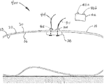
さて、図1および2に示される図面を参照して、参照番号10は、本発明と共に用いられうる医学技法に関するシステムの1つの態様である。システム10は、患者14と共に示され、より詳しくは図1では、ヒト患者14の腹腔18の縦方向の断面図に関して示され、図2では患者の腹腔の横断面図に関して示される。簡潔にするために、腔18は、臓器等がない単純化された概念型で示される。腔18は、内部表面26と外部表面30とが含まれる、腹壁などの壁22によって少なくとも部分的に画定される。壁22の外部表面30はまた、患者14の外部表面30でもありうる。患者14は、図1および2ではヒトとして示されるが、本発明の様々な態様(図1および2において示されるタイプのシステム10が含まれる)は、獣医学技法における場合のように他の動物についても用いられうる。
Referring now to the drawings shown in FIGS. 1 and 2,
さらに、システム10は、腹腔18に関して描写されるが、システム10および本発明の様々な他の態様を、胸腔、腹骨盤腔、腹腔、骨盤腔、および他の腔(たとえば、患者の胃、結腸、または膀胱などの臓器の管腔)などの、ヒトまたは動物の患者の他の体腔において利用することができる。本発明の方法のいくつかの態様において、ならびに本発明のデバイスおよびシステムの態様を用いる場合、腔内に比較的広い空間を生じるために、関心対象腔に気腹を作成してもよい。
In addition, although
図1および2に示されるように、システム10は、装置34および医療デバイス38を含み;装置は、患者の体腔にデバイスを磁気的に定置するように構成される。いくつかの態様において、患者に対するその意図される使用位置により、装置34は外部装置として記載され、デバイス38は内部デバイスとして記載されうる。示されるように、装置34を、腔18外に、患者14の外部表面30の近くに、隣接して、および/または接触して定置することができる。デバイス38は、定置可能であり(定置されることができ)、患者14の腔18内で、壁22の内部表面26の近くに、隣接して、および/または接触して定置されて示される。デバイス38は、任意の適した様式で腔18内に挿入または導入されうる。たとえば、デバイス18は、壁22における穿孔(示していない)を通して、または穿孔もしくは天然の開口部(示していない)を通して腔18内に延びるチューブもしくはトロカール(示していない)を通して、腔内に挿入されうるか、あるいは、患者14の別の部分に挿入されかつ、本開示において記載される方法などにより装置34によって腔18内で移動させてもよい。腔18が加圧されているならば、デバイス38は、腔18が加圧される前後に腔18内に挿入または導入されうる。
As shown in FIGS. 1 and 2, the
加えて、システム10のいくつかの態様には、デバイス38に連結してデバイスから離れるように延びるテザー42を有するある種のデバイス38が含まれる。描写される態様において、テザー42は、デバイス38から延びて、たとえばそれを通してデバイス38が腔18の中に導入される開口部(示していない)を通して腔18から出る。テザー42は、柔軟でありうるおよび/または伸長しうる。いくつかの態様において、テザー42には、たとえば液圧シリンダーを作動させるために、または腔18内の領域を灌注するために用いられうる流体のための1本または複数の導管が含まれうる。いくつかの態様において、テザー42には、デバイス38との電気的連絡を可能にするための1本または複数の導線が含まれうる。いくつかの態様において、テザー42には、流体のための1本または複数の導管と、1本または複数の導線とが含まれる。いくつかの態様において、テザーには、導管または導線が含まれず、そのかわりにデバイス38を定置する、移動する、または腔18から取り出すためのコードが含まれる。たとえばテザー14を用いて、デバイス34を装置38に磁気的に連結させながらデバイス34の定置を支援でき、または、デバイス38が装置34に磁気的に連結していない場合に、腔18からデバイス34を取り出すことができる。
In addition, some aspects of the
以下により詳細に考察されるように、装置34およびデバイス38は、腔18外で装置34を定置するまたは移動させることによって、デバイス38を腔18内で定置するまたは移動させることができるように、互いに磁気的に連結可能であるように構成されうる。「磁気的に連結可能」とは、直接に物理的接続することなく物理的結果を達成するように磁気的に相互作用できることを意味する。物理的結果の例とは、腔18外の装置34を移動させることによってデバイス38を腔18内で移動させること、および、腔18外の対応する位置での装置34の保持または壁22の外部表面30への接触によって、デバイス38を腔18内の位置に留まらせるまたは壁22の内部表面26に接触したままにすることである。装置34およびデバイス38を、それらの間に十分な磁気吸引力を引き起こすように構成することによって、磁気的連結が達成されうる。たとえば、装置34は、1つまたは複数の磁石(たとえば、永久磁石、電磁石等)を含み得、デバイス38は、強磁性材料を含みうる。いくつかの態様において、装置34がデバイス38を吸引し、デバイス38が装置34に吸引されるように、装置34は、1つまたは複数の磁石を含み得、デバイス38は強磁性材料を含み得る。他の態様において、装置34とデバイス38とが互いに吸引するように、装置34とデバイス38の両方が1つまたは複数の磁石を含みうる。
As will be discussed in more detail below,
それらの間に十分な磁気吸引力を引き起こすための装置34とデバイス38の構成とは、多様な他の要素(それらの間の任意の組織の厚さなど)または所望の物理的結果もしくは所望の機能を妨げ得る力を相殺するのに十分な大きさまたは強さの磁気吸引力がもたらされる構成でありうる。たとえば、装置34とデバイス38とが、示されるように各々が壁22のそれぞれの表面26または30に接触して磁気的に連結されている場合、壁22が装置34とデバイス38に対して弾性力または膨張力を発揮するような、かつ装置34とデバイス38の全ての移動が壁22の隣接する部分を同様に加圧することを必要とするような程度に、それらの間の磁力は壁22を加圧することができる。装置34およびデバイス38は、装置34によるデバイス38の移動に対するそのような妨害力に打ち勝つように構成されうる。2つの間の磁気吸引力が打ち勝つ必要がある可能性があるもう1つの力とは、存在するならば(患者の皮膚に接触する装置34などの)技法の際にどちらかが接触する表面との間に存在する、任意の摩擦である。2つの間の磁気吸引力が打ち勝つ必要がある可能性があるもう1つの力とは、テザー42の荷重および張力に関連する力、および/または、テザー42に対する摩擦力であり、これは装置34を用いたデバイス38の移動または定置に抵抗する、妨害する、もしくは影響を及ぼす可能性がある。
The arrangement of the
いくつかの態様において、デバイス38は、適した内径を有するアクセスポートを通して腔18の中に挿入されうる。そのようなアクセスポートには、従来の腹腔鏡トロカールを用いて作成されたポート、ゲルポート、切開(たとえば、腹部切開)によって作成されたポート、および天然の開口部が含まれる。デバイス38は、たとえば腹腔鏡グラスパーまたは柔軟な内視鏡などの手術用機器などの任意の細長い機器によってアクセスポートを通して押し入れられうる。
In some embodiments, the
テザー42が動力源または液圧源(示していない)に接続可能である態様において、テザーは、デバイス38に接続される前または後に動力源または液圧源(同様に流体源として記載される可能性がある)に接続されうる。
In embodiments where the
いくつかの態様において、デバイス38が腔18内に配置される場合、デバイス38は、装置34に磁気的に連結されうる。たとえばユーザーが腔18外の装置34を移動させることによってデバイス38を腔18内で移動させるのを可能にすることを含むいくつかの目的が、これによって果たされうる。2つの間の磁気的連結は、それらの間の距離を含む多数の要素によって影響を受けうる。たとえば、デバイス38と装置34の間の磁気吸引力は、それらの間の距離が減少すると増加する。その結果、いくつかの態様において、磁気的連結は、それらを分離する組織(たとえば、腹壁)を一時的に加圧することによって促進されうる。たとえば、デバイス38を腔18に挿入した後、ユーザー(外科医など)は、装置34およびデバイス38が磁気的に連結するまで、装置34(および壁22)を腔18に押し下げることができる。
In some embodiments,
図1および2において、装置34およびデバイス38は、外壁22外部の装置34を移動させることによってデバイス38が腔18内で移動することができるように、互いからの連結距離で示され、かつ互いに磁気的に連結されている。2つの構造(たとえば、装置34およびデバイス38)の間の「連結距離」は、該構造の最も近い部分の間の距離であって、それらの間の磁気吸引力が所与の用途に望ましいようにそれらを機能させるのに十分な長さの距離として、定義される。
In FIGS. 1 and 2,
2つの構造(たとえば、装置34とデバイス38)の間の「最大連結距離」は、それらの間の磁気吸引力が、所与の用途にとって望ましいようにそれらを機能させるのに十分な大きさの構造の最も近い部分の間の最大距離として定義される。それらを分離する物質(たとえば、ヒト組織)の厚さおよび組成などの要素は、所与の用途に関する連結距離および最大連結距離に影響を及ぼしうる。たとえば、図1および2において示される態様において、装置34とデバイス38の間の最大連結距離は、磁気吸引力が、デバイス38の重量、壁22の加圧によって引き起こされる力、壁22との接触によって引き起こされる摩擦力、および壁22外の装置34を移動させることによって腔18内にデバイス38を移動させるために必要な任意の他の力に打ち勝つのになおも十分なほど強い、それらの間の最大距離である。いくつかの態様において、装置34とデバイス38は、互いの一定の連結距離内で、それらの間の磁気吸引力が、固定された位置でデバイス38の重量を支持しかつ壁22の内部表面26に接触してデバイス38を保持するのに十分なほど強いが、壁22外の装置34を移動させることによってデバイス38を腔18内で移動させるのに十分なほどには強くないように、磁気的に連結可能となるように構成されうる。
The “maximum coupling distance” between two structures (eg,
いくつかの態様において、装置34とデバイス38とは、一定の距離で最小磁気吸引力を有するように構成されうる。たとえば、いくつかの態様において、装置34およびデバイス38は、装置34とデバイス38の最も近い部分の間の距離50ミリメートルで、装置34とデバイス38の間の磁気吸引力が少なくとも約20グラム、約25グラム、約30グラム、約35グラム、約40グラム、または約45グラムであるように構成されうる。いくつかの態様において、装置34およびデバイス38は、装置34とデバイス38の最も近い部分の間の距離約30ミリメートルで、それらの間の磁気吸引力が少なくとも約25グラム、約30グラム、約35グラム、約40グラム、約45グラム、約50グラム、約55グラム、約60グラム、約65グラム、約70グラム、約80グラム、約90グラム、約100グラム、約120グラム、約140グラム、約160グラム、約180グラム、または約200グラムであるように構成されうる。いくつかの態様において、装置34およびデバイス38は、装置34とデバイス38の最も近い部分の間の距離約15ミリメートルで、それらの間の磁気吸引力が少なくとも約200グラム、約250グラム、約300グラム、約350グラム、約400グラム、約45グラム、約500グラム、約550グラム、約600グラム、約650グラム、約700グラム、約800グラム、約900グラム、または約1000グラムであるように構成されうる。いくつかの態様において、装置34およびデバイス38は、装置34とデバイス38の最も近い部分の間の距離約10ミリメートルで、それらの間の磁気吸引力が少なくとも約2000グラム、約2200グラム、約2400グラム、約2600グラム、約2800グラム、約3000グラム、約3200グラム、約3400グラム、約3600グラム、約3800グラム、または約4000グラムであるように構成されうる。これらの距離は、いくつかの態様に関して連結距離または最大連結距離であってもよい。
In some embodiments, the
いくつかの態様において、装置34には2つの磁場源が含まれ、該磁場源の一方は、他方より比較的大きいかまたは他方より比較的強い磁場を有する連結磁場源であり、ゆえに磁気吸引力の大部分を生成し、該磁場源の他方はもう一方より比較的小さいかまたはもう一方より比較的弱い磁場を有し、ゆえに磁気吸引力のわずかな部分を生成する。
In some embodiments, the
図3Aおよび3Bを参照して、装置34の態様の下面および側面断面図が示される。装置34は、幅50、深さ54、および高さ58を有し、ハウジング46を含む。装置(およびより具体的にハウジング46)は、1つまたは複数の磁場源の形で少なくとも1つの磁気アセンブリを直接または間接的に支持するように構成される。示される態様において、装置34は、第一の磁場源62aと第二の磁場源62bとが含まれる装置として示される。各々の磁場源62a、62bは、連結端66および遠位端70を有する。以下により詳細に記載されるように、装置34とデバイス38とが磁気的に連結されると、連結端はデバイス38に面する。装置34のハウジング46の描写される態様にはまた、以下により詳細に記載されるように、様々な他のデバイスまたは装置を誘導、保持、または支持するためにハウジング46を通って延びる一対のガイド穴68が含まれる。他の態様において、装置34のハウジングは、たとえば、0個、1個、3個、4個、5個またはそれより多くのガイド穴68などのガイド穴68の他の任意の適した数を有しうる。いくつかの態様において、ハウジング46は、たとえばプラスチック、ポリマー、ファイバーガラス等などの磁場に対する反応性が最小である材料を含む。他の態様において、ハウジング46を省略することができ、または装置がそれ自身、磁場源を含む磁気アセンブリであるように、磁場源と一体型でありうる。
With reference to FIGS. 3A and 3B, a bottom and side cross-sectional view of an embodiment of
装置34の所与の態様の幅50、深さ54、および高さ58は各々、関連する応用にとって適した任意の大きさでありうる。いくつかの態様において、幅50は、約2.75インチ未満、深さ54は約1.75インチ未満、および高さ58は、約2.5インチ未満でありうる。加えて、いくつかの態様において、幅50は、約2インチ未満、約2.1インチ未満、約2.2インチ未満、約2.3インチ未満、約2.4インチ未満、約2.5インチ未満、約2.6インチ未満、約2.7インチ未満、約2.8インチ未満、約2.9インチ未満、または約3インチ未満でありえて;深さ54は、約1インチ未満、約1.1インチ未満、約1.2インチ未満、約1.3インチ未満、約1.4インチ未満、約1.5インチ未満、約1.6インチ未満、約1.7インチ未満、約1.8インチ未満、約1.9インチ未満、または約2インチ未満でありえて;高さ58は、約1.6インチ未満、約1.8インチ未満、約2インチ未満、約2.1インチ未満、約2.2インチ未満、約2.3インチ未満、約2.4インチ未満、約2.5インチ未満、約2.6インチ未満、約2.7インチ未満、約2.8インチ未満、約2.9インチ未満、約3インチ未満、約3.2インチ未満、約3.4インチ未満、約3.6インチ未満、約3.8インチ未満、または約4インチ未満でありうる。
The
いくつかの態様において、装置34の「連結面積」を画定することが有用でありうる。装置34の任意の所与の形状に関する「連結面積」は、一般的に、磁場源の連結端に対して近位の装置34の部分の断面積に対応し、円または長方形のいずれかを有する同じ断面積の境界を示すために必要であるより大きくない。たとえば、示される態様において、連結面積は幅50×深さ54として定義されうる。このように、幅50が約2.5インチで、深さ54が約1.5インチである装置34の1つの態様において、連結面積は約3.75平方インチである。他の態様において、連結面積は、約3平方インチ未満、約3.2平方インチ未満、約3.4平方インチ未満、約3.6平方インチ未満、約3.8平方インチ未満、約4平方インチ未満、約4.2平方インチ未満、約4.4平方インチ未満、約4.6平方インチ未満、約4.8平方インチ未満、約5平方インチ未満、約5.5平方インチ未満、約6平方インチ未満、約6.5平方インチ未満、約7平方インチ未満、約7.5平方インチ未満、または約8平方インチ未満でありうる。
In some embodiments, it may be useful to define the “connection area” of the
いくつかの態様において、装置34によって占有される空間の体積(装置の体積と呼ばれうる)は、約64立方インチ未満、約56立方インチ未満、約48立方インチ未満、約40立方インチ未満、約32立方インチ未満、約24立方インチ未満、約16立方インチ未満、約15立方インチ未満、約14立方インチ未満、約13立方インチ未満、約12立方インチ未満、約11立方インチ未満、約10立方インチ未満、約9立方インチ未満、または約8立方インチ未満でありうる。 In some embodiments, the volume of space occupied by device 34 (which may be referred to as the device volume) is less than about 64 cubic inches, less than about 56 cubic inches, less than about 48 cubic inches, less than about 40 cubic inches; Less than about 32 cubic inches, less than about 24 cubic inches, less than about 16 cubic inches, less than about 15 cubic inches, less than about 14 cubic inches, less than about 13 cubic inches, less than about 12 cubic inches, less than about 11 cubic inches, about 10 It can be less than cubic inches, less than about 9 cubic inches, or less than about 8 cubic inches.
一般的に、磁石は、北極(N極)と南極(S極)とを有する。いくつかの態様において、各磁場源の連結端66がN極であり、各磁場源の遠位端70がS極であるように、装置34は構成されうる(および、より具体的には、その磁場源が構成されうる)。他の態様において、磁場源は、各磁場源の連結端66がS極であり、各磁場源の遠位端70がN極であるように構成されうる。他の態様において、磁場源は、第一の磁場源62aの連結端がN極であり、第一の磁場源62aの凹んだ端部がS極であり、第二の磁場源62bの連結端がS極で第二の磁場源62bの凹んだ端部がN極であるように構成される。他の態様において、磁場源は、第一の磁場源62aの連結端がS極で、その凹んだ端部がN極で、第二の磁場源62bの連結端がN極で、その凹んだ端部がS極であるように構成されうる。
Generally, a magnet has a north pole (N pole) and a south pole (S pole). In some embodiments, the
示される態様において、各磁場源には、円形の断面を有する固体の円柱形の磁石が含まれる。他の態様において、各磁場源は、たとえば長方形、正方形、三角形、奇抜な形状等などの任意の適した断面形状を有しうる。いくつかの態様において、各磁場源は、以下のいずれかを含む:たとえば、1、2、3、4、5、6、7、8、9、10個もしくはそれより多くの磁石などの任意の適した数の磁石;たとえば、1、2、3、4、5、6、7、8、9、10個もしくはそれより多くの電磁石などの任意の適した数の電磁石;たとえば、1、2、3、4、5、6、7、8、9、10個もしくはそれより多くの強磁性材料片などの任意の適した数の強磁性材料片;たとえば、1、2、3、4、5、6、7、8、9、10個もしくはそれより多くの常磁性材料片などの任意の適した数の常磁性材料片;あるいは磁石、電磁石、強磁性材料片、および/または常磁性材料片の任意の適した組み合わせ。 In the embodiment shown, each magnetic field source includes a solid cylindrical magnet having a circular cross section. In other embodiments, each magnetic field source may have any suitable cross-sectional shape, such as a rectangle, square, triangle, unusual shape, and the like. In some embodiments, each magnetic field source includes any of the following: any, such as, for example, 1, 2, 3, 4, 5, 6, 7, 8, 9, 10 or more magnets Any suitable number of magnets; for example, 1, 2, 3, 4, 5, 6, 7, 8, 9, 10 or more electromagnets; Any suitable number of ferromagnetic material pieces, such as 3, 4, 5, 6, 7, 8, 9, 10 or more pieces of ferromagnetic material; for example, 1, 2, 3, 4, 5, Any suitable number of paramagnetic material pieces, such as 6, 7, 8, 9, 10 or more pieces of paramagnetic material; or of magnets, electromagnets, ferromagnetic material pieces, and / or paramagnetic material pieces Any suitable combination.
いくつかの態様において、各々の磁場源には、各々が高さ約0.5インチを有し、直径約1インチを有する円形の断面を有する、互いに対して末端同士で定置される4つの円柱状磁石(示していない)が含まれうる。これらの態様において、磁石は、磁石が互いに吸引されるようにかつ反発しないように、各々の磁石のN極が次に隣接する磁石のS極に面するように整列されうる。 In some embodiments, each magnetic field source includes four cylindrical magnets positioned end to end with respect to each other, each having a circular cross section having a height of about 0.5 inches and a diameter of about 1 inch. (Not shown) may be included. In these embodiments, the magnets can be aligned so that the north pole of each magnet faces the south pole of the next adjacent magnet so that the magnets are attracted to each other and do not repel.
適した磁石の例には、以下が含まれうる:可撓性磁石;バリウムまたはストロンチウムを含みうるようなフェライト;アルミニウム、ニッケル、およびコバルトを含みうるようなAlNiCo;サマリウムおよびコバルトを含み得、レアアース磁石とも呼ばれることがあるSmCo;ならびにネオジム、鉄、およびホウ素を含みうるようなNdFeB。いくつかの態様において、明記されたグレード、たとえばグレード40、グレード50等の磁石を用いることが望ましくなりうる。そのような適した磁石は現在、多くの販売元、たとえばMagnet Sales & Manufacturing Inc., 11248 Playa Court, Culver City, CA 90230 USA;Amazing Magnets, 3943 Irvine Blvd. #92, Irvine, CA 92602;およびK & J Magnetics Inc., 2110 Ashton Dr. Suite 1A, Jamison, PA 18929から入手可能である。いくつかの態様において、1つまたは複数の磁場源は、鉄を含む材料(たとえば、スチール)および/または常磁性材料(たとえば、アルミニウム、マンガン、白金)を含みうる。
Examples of suitable magnets may include: flexible magnets; ferrites such as may include barium or strontium; AlNiCo such as may include aluminum, nickel, and cobalt; may include samarium and cobalt, rare earths SmCo, sometimes referred to as a magnet; and NdFeB, which may contain neodymium, iron, and boron. In some embodiments, it may be desirable to use a specified grade, such as grade 40,
さて、図4を参照して、本発明の磁場源の1つの少なくとも一部として用いられてもよい円柱形磁石74の側面図が示される。磁場線78は、磁石74の磁場82を概念的に例示する。磁石74は、第一の端部86と第二の端部90とを有する。先に記載したように、磁石74は、N極とS極とを有する。磁石74などの円形の断面形状を有する円柱形の磁石に関して、N極とS極とは、一般的に円形の断面形状の中心の中を通る軸に沿って整列する。たとえば、第一の端部86がN極である場合、第二の端部90は一般的にS極であり、第一の端部86がS極である場合、第二の端部90は一般的にN極である。磁場線78によって概念的に例示されるように、外部の影響の非存在下では、磁場82は一般的に、磁石74の周りに均一に分布して、N極およびS極の中を流れる。磁石74は1つの円柱形円柱として示されるが、いくつかの態様(示していない)において、磁石74は、磁石74を形成するための直線的な配置で方向付けられた複数の、たとえば2、3、4個またはそれより多くのより短い円柱形磁石を含みうる。そのような態様において、各々のより短い磁石は同様に、N極とS極とを有し、各々のより短い磁石のS極が次に隣接するより短い磁石のN極に隣接するように方向付けられることができ、そのため各々のS極が次の隣接するN極を吸引するまたはN極に吸引される。
Referring now to FIG. 4, a side view of a
図5Aおよび5Bを参照して、図1〜3Bにおいて示される態様などの装置34の様々な態様について用いられうる磁場源62aおよび62bのそれぞれ2つの態様の透視図が示される。図5Aに示されるように、磁場源62aは、一次磁石74の形状での一次磁場源と、支持環98において一次磁石74の周りに配置される周辺磁石94aの形状での複数の周辺磁場源とが含まれる磁気アセンブリの態様である。一次磁石74は、図4の磁石74の態様と類似して(同一も含まれる)構成されうる。他の態様において、一次磁石74は、本開示において記載される、またはそうでなければ当技術分野において公知の任意の適した様式で構成されうる。示されるように、各周辺磁石94aは、円柱形であり得、一次磁石74より小さい。他の態様において、周辺磁石はそれぞれ、磁場源62aが以下により詳細に記載されるように機能することができるように任意の適した形状または大きさを有しうる。各周辺磁石94aは、一次磁石74の第一の端部86の方向を向く(たとえば、第一の端部86と実質的に同じ方向に面する)第一の端部102、および一次磁石74の第二の端部90の方向を向く第二の端部106を有しうる。支持環98は、互いに固定された関係で周辺磁石94aを支持または保持するように構成されうる。いくつかの態様において、支持環98はまた、たとえば一次磁石62aの第二の端部90からの距離110のように、一次磁石74に対して固定された関係で周辺磁石94aを支持または保持するように構成されうる。他の態様において、支持環98は、たとえば支持環98を一次磁石74に対してスライドさせることによって、距離110が調整可能であるように、一次磁石74に対してスライド可能な関係で周辺磁石94aを支持または保持するように構成されうる。
Referring to FIGS. 5A and 5B, perspective views of two embodiments of
いくつかの態様において、支持環98は、距離110を調整するために手でスライド可能であるように構成されうる。他の態様において、支持環は、一次磁石に対して支持環を回転させることによって、距離110が調整可能であるように、一次磁石の上にまたはその周りに通されるように構成されうる。いくつかの態様において、距離110は、患者の肥満指数(BMI)の関数として、それを介して装置34およびデバイス38が磁気的に連結される壁の厚さの関数として、または他の任意の有用なパラメータの関数として、予め決定された値に調整されうる。いくつかの態様において、装置34およびデバイス38の一方または双方には、装置とデバイスの間の吸引力を測定するための、および/または、吸引力が増加もしくは減少するように(たとえば、先に考察した力-距離の組み合わせの1つまたは複数を達成するように)距離110を調整すべきであることを示すシグナルを送るための、1つまたは複数のセンサー(たとえば、ひずみ計)が設けられうる。いくつかの態様において、吸引力が増加または減少するように距離110を調整すべきであることをユーザー(医師など)が感知可能な形(たとえば、光、スクリーン、聴覚アラーム等)でユーザーに示すためにディスプレイにシグナルを送ることができる。他の態様において、吸引力を増加または減少させるために、距離110の自動調整を誘発するためにプロセッサー等にシグナルを送ることができる。いくつかの態様において、磁場源62aは、一次磁石74の第二の端部90が磁場源62aの連結端66であるように、装置34と共にまたは装置34として構成されうる。
In some embodiments, the
磁石に関して先に一般的に記載したように、各周辺磁石94aは、N極とS極とを有しうる。いくつかの態様において、所与の周辺磁石94aのN極は、その第一の端部102で整列することができ、S極はその第二の端部106で整列することができ、またはその逆である。いくつかの態様において、所与の周辺磁石94aのN極は、一次磁石74に向かって内向きに放射状に方向付けることができる。いくつかの態様において、周辺磁石94aは全て、各々のN極が各々の第一の端部102で整列するように、または各々のS極が各々の第一の端部102で整列するように、同様に整列しうる。
As generally described above with respect to magnets, each
図5Bにおいて示されるように、周辺磁石94bは、長方形の形状であり得、各々の長方形の周辺磁石94bは第一の端部102、第二の端部106、内部表面114、および外部表面118を有しうる。示されるように、各周辺磁石の内部表面は、一次磁石74の方向を向くことができ、各周辺磁石の外部表面は、一次磁石74から離れる方向を向くことができる。各長方形の周辺磁石94bのN極とS極とは、任意の適した様式で方向付けることができる。たとえば、いくつかの態様において、各々のN極は、第一の端部102の方向を向き、各々のS極は第二の端部106の方向を向く。他の態様において、各々のN極は、内部表面114に向かう方向を向き、各々のS極は外部表面118の方向を向く。
As shown in FIG. 5B, the peripheral magnets 94b can be rectangular in shape, with each rectangular peripheral magnet 94b having a
図6を参照して、図5Aに示される磁場源62aの態様の側面図が、磁場源の磁場126を概念的に例示する磁場線122と共に示される。示される態様において、一次磁石74は、第一の端部86で整列したそのN極と、第二の端部90で整列したそのS極とを有し、および各々の周辺磁石94aは、その第一の端部102で整列したそのN極と、その第二の端部106で整列したそのS極とを有し、そのため一次磁石74がN-Sの配置であり、周辺磁石94aが類似のN-S配置であり、このようにN-S/N-Sの一次/周辺配置を生じる。この構成において、各々の周辺磁石94aのS極は一次磁石74のS極と反発して、各周辺磁石94aのN極は一次磁石74のN極と反発し、そのため磁場126の少なくとも一部が、磁場126を一次磁石74の第二の端部90から離れさせるように、一次磁石74の長さの少なくとも一部に沿って放射状に内向きに有効に加圧される。たとえば、この突出したまたは「集束した」磁場126は、第二の端部90を超えて、周辺磁石94aの非存在下で磁場126が延びるであろう距離より大きな距離130突出しうる。示される態様において、一次磁石74の第二の端部90は、突出した磁場126が、装置34とデバイス38の間で達成されうる最大連結距離を増加させる(周辺磁石94aを用いない場合に対して)ような磁場源62aの連結端66でありうる。
Referring to FIG. 6, a side view of the embodiment of the
加えて、いくつかの態様の場合と同様に、支持環がスライド可能であるか、またはそれ以外の方法で一次磁石に対して移動可能である場合、距離130は、距離110を調整するために一次磁石に対して支持環を移動させることによって調整されうる。この集束効果は、図5Aにおいて示される磁場源62aを参照して説明されるが、図5Bにおいて示される磁場源62bの一部である支持環98もまた、同じタイプの突出した磁場を達成するために図5Bにおいて示される一次磁石に対してスライド可能であるように構成されうる。図5Aおよび5Bにおいて示される磁場源の他の態様において、周辺磁石94aのN極が一次磁石74のS極を吸引して一次磁石74の磁場が周辺磁石94aを通じた最小抵抗経路をたどるような、N-S/S-Nの一次/周辺配置を有しうる。
In addition, as in some embodiments, if the support ring is slidable or otherwise movable relative to the primary magnet, the
図7を参照して、図1〜3Bにおいて示される装置34と共にまたは装置34として用いられうる磁場源62cの形での本発明の磁気アセンブリの1つの第三の態様の透視図が示される。磁場源62cは、一次磁石74と一次磁石74の周りに配置された複数の周辺磁石94cとを含む。先に記載した態様とは対照的に、周辺磁石94cは一次磁石74とほぼ同じ長さであり、そのため各周辺磁石の第一の端部102は一次磁石74の第一の端部86に隣接して(または実質的に同一平面上にあり)、および各周辺磁石の第二の端部106は一次磁石74の第二の端部90に隣接する(または実質的に同一平面上にある)。周辺磁石94cは、たとえば接着剤、ハウジング(示していない)、または1つもしくは複数の支持環(たとえば、図5Aおよび5Bに示される支持環98)などの任意の適した手段によって、互いに固定された関係で、および/または一次磁石74に対して固定されたまたはスライド可能な関係で支持または保持されうる。
Referring to FIG. 7, there is shown a perspective view of one third embodiment of the magnetic assembly of the present invention in the form of a magnetic field source 62c that can be used with or as the
磁場源62cの1つの態様において、一次磁石74のN極は、第一の端部86で整列して、S極は第二の端部90で整列し、各々の周辺磁石94cは、その第一の端部102で整列したそのN極と、その第二の端部106で整列したそのS極とを有し、そのため一次磁石74はN-S配置であり、周辺磁石94cは類似のN-S配置であり、したがってN-S/N-Sの一次/周辺配置を生じる。この配置において、周辺磁石94aの各々のS極は一次磁石74のS極と反発して、周辺磁石94cの各々のN極は一次磁石74のN極と反発し、そのため磁場126の少なくとも一部は、図6を参照して先に記載したように、磁場を一次磁石74の第二の端部90から離れさせるために、一次磁石74の長さの少なくとも一部に沿って放射状に内向きに有効に加圧される。他の態様において、周辺磁石の各々のN極が一次磁石74のS極を吸引して、一次磁石74の磁場が周辺磁石94cを通じた最小抵抗経路を通ることができるように、磁場源62cはN-S/S-Nの一次/周辺配置を有しうる。
In one embodiment of the magnetic field source 62c, the north pole of the
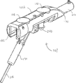
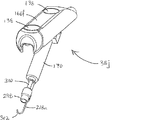
図8および9を参照すると、図8は、本発明のシステムの1つの一部として用いられうる本発明の医療デバイスの1つの別の態様であり、それに対して磁気的に連結される本発明の装置の1つを用いて体腔内で移動することができるデバイス38aを描写する。医療デバイス(たとえば、デバイス38a、38b、38c、38d、38d-1、38e、38f、38g、38h、38i、38j、38k)に、たとえば図8および9に示される構造に連結されるアーム、ツール、発光ダイオード(LED)等が含まれる本発明の医療デバイスおよびシステムの態様において、該構造は「プラットフォーム」と呼ばれることがある。
Referring to FIGS. 8 and 9, FIG. 8 is another embodiment of the medical device of the present invention that can be used as part of one of the systems of the present invention, and the present invention magnetically coupled thereto. 1A depicts a
図9は、図8における線9-9に沿って得られたデバイス38aの断面図を描写する。示される態様において、デバイス38aは、磁気吸引材料を含む。より具体的に、デバイス38aには、ハウジング134と、ハウジング134によって支持される(たとえば、連結される)2つの磁気吸引部材(この場合、第一の部材138aと第二の部材138b)とが含まれる。示される態様において、デバイス38aは、デバイス38aの少なくとも一部を通って延びる穴140を有し、たとえばファスナー、接着剤等によってツール(示されていない)、テザー42等を連結することができるように構成される。穴140の1つまたは複数は、デバイス38aがたとえばシステム400においてまたは装置404と共に機能することができるように、インサートまたはアタッチメントの全てまたは一部を保持するように構成されうる(図20〜29を参照して以下に記載される)。たとえば、穴140は、体腔内へのデバイス38aの挿入を容易にするための円錐形状のノーズ(示していない)を固定するために用いられうる。本発明のデバイスの他の態様において、穴140を完全に省略してもよく、または異なるもしくは追加の方式で構成してもよい。デバイス38aは、連結面142と作業面146とを有する。デバイス38aは装置34の態様が含まれる本発明のシステムの態様の一部でありうる。デバイス38aは、連結面142が装置34の態様に面するように、および装置34とデバイス38aとが互いに磁気的に連結した場合に、作業面146が装置34から離れて面するように、構成されうる。ハウジング134は、互いに固定された関係で部材138aおよび138bを支持または保持することができる。各々の磁気吸引部材は、デバイス38aの連結面142の方向を向く連結端150と、デバイス38aの作業面146の方向を向く遠位端154とを有する。
FIG. 9 depicts a cross-sectional view of
部材138aおよび138bは、装置34の磁場源62a、62bに磁気的に吸引される任意の適した材料を含みうる。そのような材料の例には、たとえば、磁石、強磁性材料、および常磁性材料が含まれる。いくつかの態様において、装置34およびデバイス38aの一方または双方は、装置の磁場源が各々、デバイス38aの異なる磁気吸引部材と整列できるように構成され、このことは、軸が、装置の磁場源とデバイスの磁気吸引部材とを含む所与の整列された対の実質的に中心であり、長手方向に貫通できることを意味している。本発明のデバイス、たとえばデバイス38aのいくつかの態様において、各部材138a、138bは、高さ約0.25インチで直径約0.375インチの円形の断面を有する円柱形の磁石を含む。他の態様において、各部材は、約0.15インチ、約0.16インチ、約0.17インチ、約0.18インチ、約0.19インチ、約0.20インチ、または約0.21インチの高さ;および約0.25インチ、約0.3インチ、約0.35インチ、約0.375インチ、約0.4インチ、約0.45インチ、約0.5インチ、約0.55インチ、約0.6インチ、約0.625インチ、または約0.65インチの直径を有する円形の断面を有する円柱形の磁石を含む。いくつかの態様において、各部材は、様々な大きさまたは形状の複数の磁石、たとえば円形の断面を有する円柱形の磁石5個、すなわち高さ約0.6インチで直径約0.375インチの磁石2個と高さ約0.6インチで直径約0.5インチの磁石3個;円形の断面を有する円柱形の磁石4個、すなわち高さ約0.06インチで直径約0.5インチの磁石1個と高さ約0.6インチで直径約0.625インチの磁石3個を含む。他の態様において、部材138a、138bには、強磁性または常磁性材料の任意の適した断面形状、寸法、磁石の数、または体積が含まれる。
本発明のデバイス、たとえば部材138a、138bに磁石が含まれるデバイス38aの態様において、各部材は一般的にN極とS極とを有するであろう。これらの態様のいくつかにおいて、第一の部材138aは、連結端150の方向を向くそのN極と、遠位端154の方向を向くそのS極とを有し、および第二の部材138bは、その連結端150の方向を向くそのS極と、その遠位端154の方向を向くそのN極とを有し、そのため部材138a、138bはN-S/S-N配置である。これらの態様のその他において、第一の部材138aは、連結端150の方向を向くそのS極と、遠位端154の方向を向くそのN極とを有し、および第二の部材138bは、その連結端150の方向を向くそのN極と、その遠位端154の方向を向くそのS極とを有し、そのため部材138a、138bはS-N/N-S配置である。
In the embodiment of the device of the present invention, eg,
図10を参照して、本発明のシステムの1つの一部として用いられうる本発明の医療デバイスの1つの別の態様である医療デバイス38bの透視図が示される。デバイス38bには、磁石であるボディ158が含まれる。磁石は、磁石の体積および磁気連結力を最大限にするように製造されうる。デバイス38bのこの態様は、「ボディ全体の」磁石配置として特徴付けされてもよい。デバイス38bのいくつかのそのようなタイプにおいて、ボディ158は、その連結面142がそのN極で、その作業面146がそのS極であるように構成されうる。他のタイプにおいて、デバイス38bは、ボディ158の連結面142がS極で、作業面146がN極であるように構成される。
Referring to FIG. 10, there is shown a perspective view of a medical device 38b, which is another embodiment of the medical device of the present invention that can be used as part of the system of the present invention. Device 38b includes a
図11を参照して、本発明のシステムの1つの一部として用いられうる本発明の医療デバイスの1つの別の態様である医療デバイス38cの透視図が示される。デバイス38cのボディ158は、各々が磁石である2つのボディ部分162aおよび162bを有する。2つのボディ部分162aおよび162bは間隔をあけて示されるが、それらは、たとえばねじ、ボルト、リベット、接着剤、ロッド、タブによってまたはそれらの間に生じる磁気吸引力によって互いに固定された関係で支持または保持されるように、使用前および使用の際に、たとえば穴140によって共に連結または結合されうる。デバイス38cのいくつかのタイプにおいて、ボディ150は、ボディ部分162a、162bの一方のN極がその連結面142の方向を向き、S極が作業面146の方向を向くように、およびボディ部分162a、162bの他方のS極がその連結面142の方向を向き、N極がその作業面146の方向を向くように、構成されうる。他の態様において、双方のボディ部分162a、162bのN極は連結面142の方向を向き、S極は作業面146の方向を向く。他の態様において、双方のボディ部分のS極は連結面142の方向を向いて、N極は作業面146の方向を向く。
Referring to FIG. 11, there is shown a perspective view of a medical device 38c, which is another embodiment of the medical device of the present invention that can be used as part of one of the systems of the present invention. The
図12を参照して、明快化のために断面で示した患者の壁22を超えて装置34とデバイス38とが磁気的に連結されるシステム10の態様の、絵による側面図が描写される。先に記載したように、装置34の磁場源62a、62b、およびデバイス38の磁気吸引部材138a、138bは、様々な方式で構成されうる。1つの「一致」配置において、双方の磁場源62a、62bの連結端66は、同じ極性(たとえば、いずれもN極またはいずれもS極)を有するように構成され、そのため磁場源62a、62bの連結端66はN-N配置もしくは方向、またはS-S配置もしくは方向を有する。この「一致」配置において、デバイス38は、部材138a、138bが磁石であり、部材138a、138bの連結端150は磁場源62の連結端66に対して反対方向を向くように構成されうる。たとえば、磁場源62a、62bの連結端66がN-N配置を有する場合、デバイスの部材138a、138bはS-S配置を有し得、連結端66がS-S配置を有する場合、連結端150はN-N配置を有しうる。このようにして、磁場源62a、62bおよび部材138a、138bは、磁気吸引力が装置34とデバイス38との間で最大化されうるように互いに吸引され、吸引するであろう。
Referring to FIG. 12, a pictorial side view of an embodiment of the
もう1つの「交互」配置において、磁場源62a、62bの連結端66は、異なる極性を有するように構成されうる。たとえば、第一の磁場源62aのN極が連結端66の方向を向くことができるが、第二の磁場源62bのS極がその連結端66の方向を向くことができ、またはその逆であり、そのため磁場源の連結端はN-SまたはS-N配置を有する。この「交互」配置において、デバイス38は、部材138a、138bが同様に交互の方向を有する磁石であるように構成されうる。たとえば、部材138a、138bの連結端150は、N-S方向またはS-N方向を有しうる。このように、N極を有する連結端66はS極を有する連結端150を主に吸引し、吸引され、S極を有する連結端66はN極を有する連結端150を主に吸引し、吸引される。それ以外であることが述べられている場合、各々の連結端66は、反対の極性を有する連結端150を吸引し、吸引され、各々の連結端66は類似の極性を有する連結端150を反発し、それによって反発される。そのため、「交互」配置において、装置34およびデバイス38は互いに特異的関係で吸引され、それによって装置34とデバイス38とが磁気的に連結されると、デバイス38に対する制御またはデバイスの「追跡」が改善されうる。
In another “alternate” arrangement, the coupling ends 66 of the
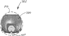
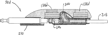
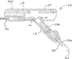
図13A〜13Gを参照して、本発明のシステムの1つの一部として用いられうる本発明の医療デバイスの1つの別の態様である医療デバイス38dの様々な図が示される。描写される態様において、デバイス38dは、プラットフォーム166、プラットフォームに連結されるアーム170、およびアームとプラットフォームの双方に連結されて、折り畳み位置から伸張位置までアームを移動させるために用いることができる(以下により詳細に記載される)シリンダー174を含む。示されるように、プラットフォーム166はハウジング134dを含み、先に記載されたように、1つまたは複数の磁気吸引部材138dを支持することができる。プラットフォーム166は、近位端178、遠位端182、および近位端178と遠位端182の間にわたる長さ186を有する。プラットフォーム166はまた、描写される態様において、プラットフォームの長さ186の少なくとも一部に沿って画定される縦方向の凹部190を有する。図13Bにおいて示されるように、プラットフォーム166はまた、最大の横方向外周192も有しうる。本発明のプラットフォームの1つの「最大の横方向外周」は、プラットフォームの最大の断面の境界を定めることができる最小の円または長方形によって画定される。
With reference to FIGS. 13A-13G, various views of a
アーム170は、近位端194と遠位端198とを有しうる。示されるように、デバイス38dはアーム170の近位端194がプラットフォーム166の近位端178に対して遠位であるように構成されうる。近位端194と178とが離れる距離は、たとえば、プラットフォームの長さの1、5、10、20、30、40、もしくは50%、またはプラットフォームの長さの0〜50%までの任意の範囲もしくは整数などの、プラットフォームの近位端からその遠位端までのプラットフォームの長さの百分率として表記されうる。(1)図13Cにおいて示されるようにアーム170の遠位端198がプラットフォーム166に隣接する、すなわちプラットフォーム166に対してアーム170が実質的に平行である、折り畳み位置と、(2)アーム170の遠位端190とプラットフォーム166の間隔があいている、すなわちアーム170がプラットフォーム166に対して非ゼロ度の角度を向いた、伸張位置との間で、アーム170が移動可能であるように、アーム170はプラットフォーム166に連結されてもよい。この態様において示されるように、アーム170はカムスロットおよびピンによってプラットフォーム166に連結されうる。たとえば、示される態様において、プラットフォーム166には、プラットフォーム166の縦軸に対して平行で、プラットフォームの中を横方向に延びる第一のカムスロット202、および第一のカムスロット202に対して間隔をあけかつ角度をなして配置され、プラットフォーム166の少なくとも一部の中を横方向に延びる1つまたは複数の追加のカムスロット202(描写される態様では2個)が含まれる。示される態様において、アーム170の近位端194を、カムスロット202および202を通って延びるピン206によってプラットフォーム166に連結することができ、それによってアーム170は、図13Cの折り畳み位置から図13Aの伸張位置まで移動する場合に、プラットフォーム166の遠位端182の方向に縦方向に、およびプラットフォーム166から外向きに角度をなすように双方の方向に移動する。アーム170が折り畳み位置にある場合、アーム170の縦軸は、好ましくは最大の横方向外周内に配置される。同様に、アーム170が折り畳み位置にある場合、アームの少なくとも一部は、腔18への挿入および腔からの取り外しの際にプラットフォーム166がアーム170に対して何らかの保護を提供するように、アーム170の側面の大部分がプラットフォームに接するように、凹部190内に配置されうる。
The
図13Fにおいて最もよく示されるように、シリンダー174には、ピストン210と注入口214とが含まれうる。ピストン210はアーム170の近位端194に直接または間接的に連結されうる。注入口214は、アーム170が伸張位置まで移動するようにプラットフォーム166の遠位端182に向かってピストン210を伸長させるため、およびアームが折り畳み位置まで移動するようにプラットフォーム166の近位端178に向かってピストン210を引き戻すために、流体が送達および除去されうる、または圧縮および脱圧縮されうるように、テザー42の中を、テザー42と共に、またはテザー42に沿って流れる流体導管(示していない)に連結されうる。
As best shown in FIG. 13F, the
デバイス38dにはまた、ツール218、たとえば刃、フック、焼灼ツール、または医学技法にとって有用もしくは有利である可能性がある他の任意のツールが含まれうる。示される態様において、ツール218は焼灼ツールである。焼灼ツール218は、たとえばアームの遠位端198でまたはその近傍でアーム170に連結されうる。焼灼ツール218は、テザー42の中を、テザー42と共に、またはテザー42に沿って流れる導線(示していない)によって動力を供給されうる。さらに、デバイス38dの使用時に、導線を、ボディ166の近位部分に位置して、たとえば図13B、13D、13Fおよび13Gにおいて見ることができる切り欠きまたはチャンネル220の中に定置することができる。いくつかの態様において、焼灼ツール218を、たとえば公知の電気外科ユニット(たとえば、ピーク間で9,000ボルトおよび/または390 kHzシヌソイドまで)と適合性である電圧などの高電圧によって正に帯電させることができ、それによって焼灼ツール218が接地された患者の肉または組織に接触すると、回路が完成して、焼灼ツール218が比較的小さい力で肉または組織を切断または焼灼することができる。デバイス38dのみならず、焼灼ツールが含まれる本発明の医療デバイスの他の態様は、アーム170が折り畳み位置に存在する場合、焼灼ツール218の遠位端が、例えば約0.1インチ、約0.2インチ、約0.3インチ、約0.4インチ、約0.5インチ、約0.6インチ、約0.7インチ、約0.8インチ、約0.9インチ、約1.0インチ、約1.2インチ、約1.4インチ、約1.6インチ、約1.8インチ、もしくは約2インチまたはそれらを上回る距離だけ、プラットフォーム166の遠位端182から間隔をあけている(ツールとプラットフォームの双方の軸に対して平行な線に沿って)ように構成されうる。別の言い方をすれば、デバイス38dは、アーム170が折り畳み位置に存在する場合に、プラットフォームの長さを上回る距離だけプラットフォームの近位端から間隔をあけた位置に、ツール218の遠位端が位置するように構成されうる。いくつかの態様において、ツール218は、たとえば腔18へのデバイス38dの挿入または腔18からデバイスの取り外しを容易にするために、取り外し可能な非外傷性の先端部または他のカバー(示していない)によって覆われうる。アーム170が折り畳み位置に存在する場合、焼灼ツール218またはもう1つのツール218の縦軸は、アーム170の縦軸と平行であり得、同様にプラットフォーム166の最大の横方向外周内でありうる。
いくつかの態様において、デバイス38dは、先に記載したように、腔18に挿入されて、装置34に磁気的に連結されうる。デバイス38dと装置34とが互いに磁気的に連結すると、またはそれ以外の方法でデバイス38dが腔18内の位置に固定されると、ユーザーは、ツール(たとえば、焼灼ツール218)をシリンダー174に対してピストン210が伸長するようにシリンダー174を作動させることによって、折り畳み位置(たとえば、図13B、13C)から伸張位置(たとえば、図13A、13D)へと展開するまたは広げることができる。たとえば、シリンジ、手押しポンプ、ガスボトル(たとえば、流体の流れを制御するためのバルブ、ポンプ等を備えた)、圧調節器、または他の任意の適した起源などの液圧源(示していない)によって、シリンダー174を作動させることができる。
In some embodiments, the
いくつかの態様において、アーム170が伸張位置にある場合、ユーザーは、腔18外の磁気的に連結された装置34を移動させることによって、デバイス38dを移動させて腔18内でのその位置を調整することができる。いくつかの態様において、ユーザーはさらに、壁22がそのようなピッチおよび偏揺れの動きまたは調整を許容するために十分柔軟である場合に、装置34を移動させるまたは装置34のピッチおよび偏揺れを調整することによって、デバイス38dを移動させるまたはデバイス38dのピッチおよび偏揺れを調整できる可能性がある。本発明のデバイスおよびシステムの態様は、デバイス38dが操作位置(たとえば、腔18内で作業を行うために、焼灼ツール218がユーザーにとって許容可能な位置に存在する)にある場合、焼灼ツール218は、電気外科ユニット(フットペダルあり、またはなし)、動力源等を通して行う場合が含まれる任意の適した形式で起動または帯電されうるように構成されうる。本発明のデバイスおよびシステムの態様は、焼灼ツール218が、たとえば従来の焼灼動力源などの従来の方法およびシステムによって動力が与えられて作動させることができるように構成されうる。そのような動力源は、物理的テザー(たとえば、テザー42または以下により詳細に記載される装置404)による場合が含まれる任意の適した形式で焼灼ツール218に電気的に連結されうるまたは電気的に連絡されうる。本発明のデバイスおよびシステムの態様は、ユーザーが、フットペダル、スイッチ、音声作動起動装置、または他の任意の適した方法、システム、もしくはデバイスを用いて、焼灼ツール218を起動することができるように構成されうる。本発明のデバイスおよびシステムの他の態様は、焼灼ツール218がジョイスティックによって、または他の比較的より複雑なユーザーインターフェースによって展開(たとえば、アーム170を折り畳み位置から伸張位置に展開させることができる)および/または制御されうるように、構成されうる。
In some embodiments, when the
図13Hおよび13Iを参照して、本発明のシステムの1つの一部として同様に用いられうる、本発明の医療デバイスの1つの別の態様である医療デバイス38d-1の側面図および断面図がそれぞれ示される。医療デバイス38d-1は図13A〜13Gの医療デバイス38dといくつかの点において類似であることから、一般的にそれらの差のみを本明細書において記載する。詳しくは、デバイス38d-1は、シリンダー(たとえば、174)よりむしろ、ハウジング134dに対して固定された関係で連結されるロータリーモーター250を含む。さらに、アーム170は、ピンまたは軸222によってハウジング134dに対して回転可能に連結され、およびアーム170は、かさ(またはマイター)歯車270によってモーター250に連結され、それによってモーター250の回転を、ピン222の周囲にアーム170を回転させるように(たとえば、折り畳み位置と伸張位置との間でアーム170を移動させるため)構成することができる。
With reference to FIGS. 13H and 13I, there is a side view and cross-sectional view of a
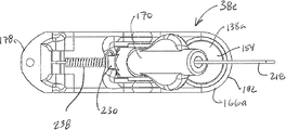
図14A〜14Cを参照して、本発明のシステムの1つの一部として同様に用いられうる本発明の医療デバイスの1つの別の態様である医療デバイス38eの様々な図が示される。医療デバイス38eは、図13A〜13Gの医療デバイス38dといくつかの点において類似であり、一般的にそれらの差のみを本明細書において記載する。デバイス38eの一部であるタイプのアーム170は、アーム170が、ピンまたは軸222によってプラットフォーム166aに枢動的に連結され、それによってアーム170は(1)アーム170の遠位端198がプラットフォーム166aに隣接する、または図13Cにおいて示されるようにアーム170がプラットフォーム166aに対して実質的に平行である折り畳み位置と(2)アーム170の遠位端190とプラットフォーム166aとの間隔があいている、またはアーム170がプラットフォーム166aに対して非ゼロ角の方向を向いている伸張位置との間で、移動可能である。加えて、示されるように、アーム170に、磁気吸引部材226を含めることができ、たとえば先に記載された磁気の原理を用いて、部材226と部材138aの一方または双方を適合させることができ、それによって少なくともアーム170が折り畳み位置にある場合に、磁気吸引力が部材226と部材138aとの間で生じる。
Referring to FIGS. 14A-14C, various views of a
アーム170にはまた、図14Cにおいて最もよく示されるように、プラットフォームに対するアーム170の動きの範囲を制限するために、プラットフォーム166aの一部に接触または係合するように構成された出張りまたは止め具230が含まれうる。たとえば、出張り230は、角度234が、約20度、約25度、約30度、約35度、約40度、約45度、約50度、約55度、約60度、約65度、約70度、約75度、約80度、約85度、または約90度を超えることができないように構成されうる。デバイス38eにはまた、アーム170を伸張位置に向けて偏らせるためにばね238が含まれうる。いくつかの態様において、アーム170が折り畳み位置にある場合にプラットフォームの部材138aとアームの部材226の間の磁気吸引力が、(1)外部の力の非存在下では、ばねの張力に対抗して折り畳み位置でアームを保持するのに十分なほど大きいように、かつ(2)ばね(たとえば、ばね238)の張力が伸張位置までアームを引っ張るように、表面(体腔内の臓器または組織片など)に対してアームを衝突または振動させることによって生じた外部の力には十分に負けるほど小さいように、デバイス38eが構成されうる。たとえば、いくつかの態様において、ばねの軸に沿って提供される付勢力(アームが折り畳み位置に存在する場合)は、部材138aと部材226の間の磁気吸引力より大きく、たとえばデバイス38eを上記のように機能させるために少なくとも約105パーセント、110パーセント、115パーセント、または任意の他の適した百分率もしくは比率であるか、またはそれより大きい。加えて、プラットフォーム166aには、プラットフォーム166aに対してテザー42を固定するためにテザーポート242および押しねじ246とが設けられうる。たとえば、押しねじ246をゆるめて、テザー42をテザーポート242内に挿入または接続することができ、テザーがプラットフォームから引っ張られないように、押しねじを締めて、テザーの部分を締め付けるまたは挟むことができる。示される態様にはまた、焼灼218との電気的連絡を可能にして動力を提供するために、導線(示されていない)がチャンネル244の中を通ることができるように、アーム170を通って延びるチャンネル244が含まれる。
図15A〜15Dを参照して、本発明のシステムの1つの一部として同様に用いられうる本発明の医療デバイスの1つの別の態様である医療デバイス38fの様々な図が示される。医療デバイス38fは、図14A〜14Cの38eおよび図13A〜13Gの38dの医療デバイスに対していくつかの点で類似であり、一般的に本発明の医療デバイスのこれらの他の態様との差のみを本明細書において記載する。医療デバイス38fは、アーム170がピンまたは軸222によってプラットフォーム166bに枢動的に連結されるように構成される。これはまた、アーム170をばね等(示していない)によって閉じた位置に向けて偏らせることができるように構成されうる。デバイス38fには、回転する出力シャフトまたは滑車254を有するモーター250、プラットフォーム166bに連結された1つまたは複数の滑車258、およびコード262が含まれる。示されるように、コード262は、一方の端部でアーム170に接続することができ、各滑車258の一部のまわりを接触して通り、他方の端部でモーター250の滑車254を接続することができる。操作時に、コード262を巻くようにモーター250を作動させて、それによってアーム170を折り畳み位置から伸張位置に引っ張ることができ、およびコード262を解くようにモーター250を作動させて、それによって付勢ばね(示していない、しかしたとえばデバイス38eに関連するばね238など)によって折り畳み位置に引き戻すようにアーム250を開放することができる。モーター250は、液圧式または電気式であり得、先に記載したように、導管または導線の接続を可能にするために1つまたは複数のコネクタ266を含めることができ、それによってモーター250を作動させるための電流または液圧流体を供給することができる。説明を容易にするために、磁気吸引部材138a、138bは図15Dでは省略されている。
Referring to FIGS. 15A-15D, various views of a
図16A〜16Dを参照して、本発明のシステムの1つの一部として同様に用いられうる本発明の医療デバイスの1つの別の態様である医療デバイス38gの様々な図を示す。医療デバイス38gは、図15A〜15Dの38f、図14A〜14Cの38e、および図13A〜13Gの38dの医療デバイスに対していくつかの点で類似であることから、一般的に本発明の医療デバイスのこれらの他の態様との差のみを本明細書において記載する。医療デバイス38gは、アーム170がピンまたは軸222によってプラットフォーム166cに枢動的に連結されるように構成される。デバイス38gには、コネクタ266と共にモーター250が含まれる。モーター250およびアーム170を、(たとえば)45度のかさ歯車の形をとることができるかさ歯車270に連結させることができる。その結果、モーター250を作動させることによってアーム170を折り畳み位置から伸張位置に展開できるように、モーター250によって生じた回転を、アーム170の回転運動に変換することができる。加えて、デバイス38gには、本実施例においてねじ278によってプラットフォーム166cに連結されるクランプ部分274が含まれうる。ねじ278をゆるめることによって、テザー42がそれらの間に挿入されて、コネクタ266に接続されうるように、クランプ部分274を、プラットフォーム166cから分離させることができる。次に、たとえばテザーに対するひずみの開放を提供するために、ねじ278を締めることによって、テザーをクランプ部分274とプラットフォーム166cとの間で締付けることができる。
Referring to FIGS. 16A-16D, various views of a medical device 38g, which is another embodiment of the medical device of the present invention that can also be used as part of one of the systems of the present invention, are shown. The medical device 38g is generally similar in some respects to the
図17A〜17Cを参照して、本発明のシステムの1つの一部として同様に用いられうる本発明の医療デバイスの1つの別の態様である医療デバイス38hの様々な図を示す。医療デバイス38hは、図16A〜16Dの38g、図15A〜15Dの38f、図14A〜14Cの38e、および図13A〜13Gの38dの医療デバイスに対していくつかの点で類似であることから、一般的に本発明の医療デバイスのこれらの他の態様との差のみを本明細書において記載する。医療デバイス38hには、プラットフォーム166dの縦軸に対して垂直であるシャフト286を有するモーター282が含まれる。アーム170は、シャフトの回転がアーム170の回転に直接変換されるようにシャフト286に連結され得、それによって、アームを折り畳み位置から伸張位置に展開させることができる。デバイス38hの他のタイプには、シャフト286の各回転を、約5度、約10度、約15度、約20度、約30度、約45度、約90度、約120度、約180度、約225度、約270度、または約315度に変換するギヤ減速機構(示していない)が含まれる。加えて、モーター282は、折り畳み位置と伸張位置の間の角度290が、モーター282を所望の角度に作動させることによって調整されうるように構成されうる。モーター282として用いるために適したモーターの例には、パンケーキギヤヘッドモーター、流体モーター(液圧式および空気式の双方)、流体シリンダーラックアンドピニオン駆動装置、ボールねじ等が含まれる。いくつかの態様において、デバイス38hは、アーム170がプラットフォーム166dに対して展開された位置(たとえば、角度290)にある場合に、先端部218がアーム170に対して回転可能であるように構成される。たとえば、いくつかの態様において、アーム170は、アーム170に対して先端部218を回転させるように構成されたモーターを含みうる。いくつかの態様において、デバイス38hは、アーム170がプラットフォーム166dに対して側方に回転可能であるように構成されうる。たとえば、示される態様において、デバイス38hは、アーム170がプラットフォーム166dに対して垂直平面(水平軸の周囲)で回転するように構成される。回転軸は、たとえば、プラットフォーム166dに対する先端部218の垂直方向の変位が低減されるように、プラットフォーム166dに対して(たとえば、アーム170がプラットフォーム166dに対して垂直および側方のどちらにも移動する経路に沿って、アームがその折り畳み位置からその展開位置へと移動するような、45度の角度で)角度をなすことができる。
Referring to FIGS. 17A-17C, various views of a
図18A〜18Cを参照して、本発明のシステムの1つの一部として同様に用いられうる本発明の医療デバイスの1つの別の態様である医療デバイス38iの様々な図が示される。医療デバイス38iは、図17A〜17Cの38h、図16A〜16Dの38g、図15A〜15Dの38f、図14A〜14Cの38e、および図13A〜13Gの38dの医療デバイスに対していくつかの点で類似であることから、一般的に、本発明の医療デバイスのこれらの他の態様との差のみを本明細書において記載する。図13A〜13Gにおいて示されるデバイス38dと同様に、アーム170は、カムスロット202およびピン206によってプラットフォーム166eに連結され、シリンダー174によって折り畳み位置と伸張位置との間で作動されうる。加えて、デバイス38iにはツール218aに連結されたモーター294が含まれ、これは、モーターが作動されるとツールをその縦軸の周りに回転させるように構成されている。モーター294として用いるための適したモーターの例には、電気モーター、液圧モーター、およびセラミックモーターが含まれる。示される態様において、ツール218aは、ベース部分298と、エネルギーを与えられうる電極表面(たとえば、「作業表面」)を含むフック部分302とが含まれる焼灼ツールである。このように、焼灼ツールは、起動されると、それが切断および/または焼灼機能を行うことができるように(そのいくつかは、フックのサイズに応じて複雑であってもよい)、ならびに起動されない場合、組織および臓器などのもの、およびいくつかの場合において縫合糸、血管等を引っ張るまたは押すために用いられうるように構成される。
Referring to FIGS. 18A-18C, various views of a medical device 38i, which is another embodiment of the medical device of the present invention that can also be used as part of one of the systems of the present invention, are shown. The medical device 38i has several points relative to the
図19A〜19Cを参照して、本発明のシステムの1つの一部として同様に用いられうる本発明の医療デバイスの1つの別の態様である医療デバイス38jの様々な図が示される。医療デバイス38jは、図18A〜18Cの38i、図17A〜17Cの38h、図16A〜16Dの38g、図15A〜15Dの38f、図14A〜14Cの38e、および図13A〜13Gの38dの医療デバイスに対していくつかの点で類似であることから、一般的に、本発明の医療デバイスのこれらの他の態様との差のみを本明細書において記載する。図16A〜16Dにおいて示されるデバイス38gと同様に、アーム170は、ピンまたは軸222によってプラットフォーム166fに枢動的に連結されて、モーター250およびかさ歯車270によって折り畳み位置と伸張位置との間で作動されうる。加えて、デバイス38jには、ピストン310と注入口314とを有するシリンダー306が含まれる。ピストン310は、シリンダー306を作動させることによって、焼灼ツールがその縦軸に沿って外向きに(たとえば、非伸長位置から伸長位置まで)伸長されうるように、焼灼ツール218aに連結されうる。注入口314は、たとえばプラットフォーム166f内に取り付けられたまたはその中で画定されるポートまたは導管(示していない)によって先に考察したように、テザー42の流体導管に連結されうる。加えて、デバイス38jには、ピストン310および/または焼灼ツール218aに連結されて、ピストンと平行でアーム170の一部内で画定されるガイド通路322に定置される(およびその中でスライド可能である)ガイド棒318が含まれうる。ガイド棒318および/または通路322は、ピストン310がシリンダー306に対して回転しないように、またはピストン310がシリンダー306に対して既定の位置を超えて伸長しないように構成されうる。
Referring to FIGS. 19A-19C, there are shown various views of a
本発明の医療デバイス(たとえば、38、38a、38b、38c、38d、38e、38f、38g、38h、38i、38jおよび38k)の態様は、任意の適した方法によって作成され、任意の適した材料または複数の材料を含みうる。たとえば、プラットフォーム(たとえば、166、166a、166b等)およびアーム170は、フライス加工もしくはターニングなどの従来のサブトラクティブ法によって機械加工されうる、またはラピッドプロトタイピングのために用いられる方法などのアディティブ法によって形成されうる;およびプラスチック、金属、コンポジット、合金等などの適した生物学的適合性の材料を含みうる。たとえば、ベアリング、歯車、流体シリンダー、ケーブル、導線、導管等などの様々な他の成分は、たとえばSmall Parts, Inc., Florida, USA;McMaster-Carr Supply Company, Georgia, USA;Stock Drive Products/Sterling Instrument, New York, USA;SMC Corporation of America, Indiana, USA;Bimba Manufacturing Company, Illinois, USA;Festo Corporation, New York, USA;Faulhaber Group, Germany;およびMicroMo Electronics, Inc., Florida, USAなどの一般的な機械/電気販売元から得ることができる。同様に、本発明のシステムおよび/または医療デバイスの態様のパーツまたは成分は、たとえば従来の手動での技術である、固着、圧入、生物学的適合性のエポキシまたは接着剤による固定等を含む、任意の適した手段を通して組み立てられうる。テザー42が含まれる本発明のシステムおよび医療デバイスの態様において、テザー42はデバイスのツールを動力源に連結させるために役立ち、動力源は、流体(液体または気体)圧力源などの液圧源でありうる。流体圧力源の例には、手押しポンプ、電気ポンプ、圧調節器を有する加圧ガスボトル等が含まれる。テザー42をツールに連結することができる動力源が電源である態様において、そのような動力源の例には、バッテリー、電気増幅器等が含まれる。ツールが焼灼ツールである場合に用いられうる電力源の他の例には、先に言及したように、たとえばValleyLab, Colorado, USA;Erbe USA, Inc., Georgia, USAなどの販売元から入手可能な電気外科ユニットまたは動力源などの電気外科ユニットが含まれる。いくつかの態様において、テザー42には、2本以上の導線および/または導管が含まれうる。たとえば、テザー42には、液圧流体(気体または液体)および/または電力を関連するデバイス(たとえば、38、38a、38b、38c、38d、38e、38f、38g、38h、38i、38j、および38k)の様々な成分に送達するために適当であるように、1本の導線と1本の導管、2本の導線と1本の導管、3本の導線等が含まれうる。追加の例として、テザー42には、流体導管の周りに同軸に導電性部分が含まれうる、または流体導管内に導電性部分(絶縁された)が含まれうる(たとえば、導線に隣接する導管内に流体を流れさせるように構成される)。
Embodiments of the medical devices of the present invention (eg, 38, 38a, 38b, 38c, 38d, 38e, 38f, 38g, 38h, 38i, 38j and 38k) can be made by any suitable method and any suitable material Or it may include multiple materials. For example, the platform (eg, 166, 166a, 166b, etc.) and
モーターを用いて、アーム170がユーザーによって折り畳み位置から伸張位置まで展開されうるように構成されている本発明のデバイスおよびシステムの態様(たとえば、デバイス38e、38f、または38iが含まれる態様)において、モーターは、いくつかの態様において、三段スイッチ(たとえば、時計回り、ニュートラルまたはオフ、および反時計回り)などのスイッチ(示していない)によって制御されうる。同様に、シリンダーを用いて、アーム170がユーザーによって折り畳み位置から伸張位置まで展開されうるように構成されている本発明のデバイスおよびシステムの態様(たとえば、デバイス38dまたは38hが含まれる態様)では、シリンダーは、いくつかの態様において、三段スイッチ(たとえば、展開または前進、ニュートラルまたはロック、および収縮または後退)などの、液圧源(示していない)を制御するスイッチによって制御されうる。いくつかの態様において、アーム170またはデバイスの別の部分には、アームの位置を感知するための位置センサーが設けられうる。適した位置センサーの例には、電位差計、リミットスイッチ、およびエンコーダーが含まれる。これらの態様のいくつかにおいて、位置センサーは、アームが既定の位置に達した場合にアームの動きを停止させるように構成されうる。
In embodiments of the devices and systems of the present invention (e.g., including
図20を参照して、そこで示され、参照番号400によって表されるのは、本発明の医療デバイスの1つとの電気的連絡を可能にするためのシステムの1つの態様である。システム400は、デバイス38との電気的連絡を可能にするための装置を含むが、システムは本明細書において記載されるデバイス(たとえば、図21A〜21Dのデバイス38k)のいずれかと共に用いられうる。より詳しくは、示される態様において、システムは、2つの装置404(図23A〜23Cにおいてより詳細に示され、以下により詳細に記載される)、および装置を固定するための2つのクランプまたはロック408を含む。示されるように、各装置404は、患者14の外部表面30でもありうる壁22の外部表面30の穿孔を通って延びる。システム400のいくつかのタイプには、プラス接続部416aとマイナス接続部416bとが含まれうる動力源412が含まれる。システム400によって表されるタイプの本発明のシステムのいくつかの態様において、装置または複数の装置は、それまたはそれらとデバイス(たとえば、医療デバイス38)との間の電気的連絡を可能にするように、および動力源の接続部に接続可能であるように構成される。例示的な装置404を、図23A〜23Cを参照して以下に記載する。たとえば、2つの装置404の一方は、接続部416aまたは416bの一方に接続可能であり得、2つの装置404の他方は、接続部416aまたは416bの他方に接続可能でありうる。動力源を含むタイプのシステム400において、動力源は、任意の適した電圧または電流源を含み得、および/またはたとえばコンセント、電圧変換器、およびAC/DC変換器、電圧調節器、またはこれらの任意の適した組み合わせなどの、動力源から電圧または電流を改変するための任意の適したデバイスまたはシステムを含みうる。
Referring to FIG. 20, shown there and represented by
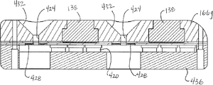
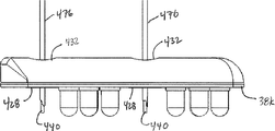
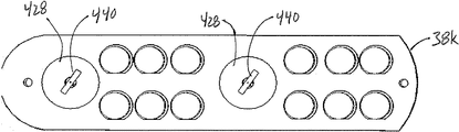
図21A〜21Dを参照して、本発明のシステムの1つの一部として同様に用いられうる本発明の医療デバイスの1つの別の態様である医療デバイス38kの様々な図が示される。医療デバイス38kは、図19A〜19Cの38j、図18A〜18Cの38i、図17A〜17Cの38h、図16A〜16Dの38g、図15A〜15Dの38f、図14A〜14Cの38e、および図13A〜13Gの38dの医療デバイスに対していくつかの点で類似であることから、一般的に、本発明の医療デバイスのこれらの他の態様との差のみを本明細書において記載する。デバイス38kは、アーム170も、アーム170を移動させるための任意の対応する構造も伴わずに示される。代わりに、デバイス38kは、デバイスが用いられる腔18または腔内の一部もしくは点を照明するために用いられうる複数の光源420と共に示される。光源420は、たとえば発光ダイオード(LED)が含まれる任意の適した形状をとりうる。デバイス38kは、たとえばシステム400の装置(たとえば、装置404)と共に用いられるように適合されうる。たとえば、デバイス38kには、たとえば1、2、3個またはそれより多い開口部424などのデバイス38kと共に用いられる装置の数に対応する多数の開口部424が設けられうる。加えて、デバイス38kには、たとえばデバイス38kの作業面146でまたはその近傍で導電性部分428が設けられうる。いくつかの態様において、デバイス38kの導電性部分428は、各開口部424に隣接しうる;他の態様において、デバイス38kの導電性部分428は開口部424を実質的に取り囲むことができる。導電性部分428はたとえば、銀、銅、銀を被覆した銅、または他の任意の適した導電性材料(たとえば、金属、ポリマー)が含まれる任意の適した形をとりうる。いくつかの態様において、導電性部分428には、各々、装置404が張力下にある場合に、デバイス38kに対する装置404(および/またはアンカー440)の回転に耐えるためなどの、装置404の一部(たとえば、アンカー440)を受容するように構成されている溝(たとえば、開口部424の反対側の同一直線上の部分)が含まれる。デバイス38kをこのように構成した結果、装置404は開口部424の中を通過することができ(通路424としても記載されうる)、装置と導電性部分428との間で電気的連絡が可能であるように、隣接する導電性部分428に接触する。導電性部分428の1つは、プラス接続部のために用いられ、他の導電性部分はマイナス接続部のために用いられうる。デバイス38kはまた、光源420が、たとえばワイヤ、導電トレース、または直接接続を用いて導電性部分と電気的に連絡するように構成されることができ、それによって装置が動力源412に接続されると、電流が流れて、光源にエネルギーを与えて発光させる。たとえば、デバイス38kのいくつかの態様は、LEDを導電性部分428に電気的に連結させる導電トレースを含む、および/または極性(たとえば、装置404の極性)とは無関係に操作するように構成された、および/または装置404の極性が逆転した場合に(たとえば、意図されるまたは予想される極性から)、極性を逆転させるように構成された、回路を含む、回路基板(たとえば、プリント回路基板またはPCB)を含みうる。いくつかの態様において、装置404は、適当な極性に対応するように構成される(たとえば、異なるサイズまたは形状によって)。たとえば、いくつかの態様において、プラスの装置404(正極のために構成された装置)は、マイナスの装置404(負極のために構成された装置)より大きいサイズおよび/または異なる形状を有するように構成される。加えて、デバイス38kには、示されるように、開口部への装置(たとえば、404)の挿入を容易にするために、各開口部424の1つの端部で逆円錐形状を有しうる広口のテーパ部分432が含まれうる。
Referring to FIGS. 21A-21D, various views of a
図21Cおよび21Dにおいて示されるように、デバイス38kにはまた、たとえば接着剤、クリップ、ねじ、リベット、ボルト、または他の任意の適した手段などの任意の適したデバイスまたは構造によってプラットフォーム166gに連結されるカバー436が含まれうる。カバーは、光源420によって発せられた光の少なくともいくつかの部分がカバーの中を通過するように構成されうる。いくつかの態様において、カバー436は、実質的に透明であるように構成されうる。カバー436のために用いられる材料は、導電性部分428による電気ショックを受けないように腔18の内部を保護するように、および装置のいかなる部分も腔18から落下しないように選ばれうる。カバーは、たとえば透明または半透明なポリカーボネート(たとえば、LEXAN商標の熱可塑性のポリカーボネート樹脂)等を含みうる。いくつかの態様において、カバーは、破砕に対して抵抗性で、非導電性であり、および/または滅菌されうる。
As shown in FIGS. 21C and 21D,
図22A〜22Eを参照して、本発明のシステムの1つの一部として同様に用いられうる本発明の医療デバイスの1つの別の態様である医療デバイス38mの様々な図が示される。医療デバイス38mは、図21A〜21Dの38k、図19A〜19Cの38j、図18A〜18Cの38i、図17A〜17Cの38h、図16A〜16Dの38g、図15A〜15Dの38f、図14A〜14Cの38e、および図13A〜13Gの38dの医療デバイスに対していくつかの点で類似であることから、一般的に、本発明の医療デバイスのこれらの他の態様との差のみを本明細書において記載する。モーター250および歯車270は、図16A〜16Dのデバイス38gのものと類似である。しかし、開口部424、導電性部分428、およびテーパ部分432は、図21A〜21Dのデバイス38kと類似である。加えて、デバイス38mは、導電性部分428とモーター250の間に延びてそれらの間を電気的に連絡するコネクタ438と共に示され、それによってデバイス38mは、本開示において記載されるように電気的連絡を可能にするために、装置404によって機能するように構成される。コネクタ438は、たとえば導電性ワイヤ(絶縁または非絶縁)、導電性部分428と共に一体形成された導電性コネクタ、または他の任意の適したコネクタなどの任意の適した導電性コネクタを含みうる。
Referring to FIGS. 22A-22E, various views of a
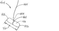
図23Aを参照して、装置404の透視図が示される。示されるように、装置404は、アンカー440と、接続点448でアンカー440に接続された導線444とを含みうる。アンカーは、第一の端部452、第二の端部456、および第一の端部452と第二の端部456の間にわたる長さ460を有しうる。いくつかの態様において、接続点448は、第一の端部452と第二の端部456の間のほぼ中心でありうる。以下により詳細に記載されるように、アンカー440にはまた、アンカー440の一部の周りに(または、示されるような円柱様の形状をアンカーが有する場合には囲んで)伸長するまたはアンカー440の周り全てに伸長する、凹部464が含まれうる。いくつかの態様において、アンカー440は、チューブおよび/または管状(中空の)断面を含み得;かつ/またはステンレススチール(たとえば、長さ460を有するステンレススチールチューブ)を有しうる。アンカー440および導線444は、任意の適した様式(たとえば、クリンプ加工および/またははんだ付け)で互いに連結されうる。
Referring to FIG. 23A, a perspective view of the
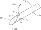
図23Bおよび23Cを参照して、導線444の2つの態様の断面図が示される。図23Bにおいて示される第一の態様において、導線444は、第一のまたは中心の導電性部分468と、導電性部分468の周りに配置された外側の絶縁材料層472とを含む。これらの2つの部分は、示されるように実質的に同軸でありうる。いくつかの態様において、導線444は、磁石ワイヤを含む(たとえば、中心の導電性部分468は銅を含み得、かつ/または絶縁材料472はエナメルを含みうる)。図23Cにおいて示される第二の態様において、導線444aは、第一または中心の導電性部分468a、第一の導電性部分468aの周りに配置された第一の絶縁材料層472a、第一の絶縁材料層472の周りに配置された第二の導電性部分476、および第二の導電性部分472の周りに配置された第二のまたは外側の絶縁材料層480を含む。これらの4つの部分は、示されるように実質的に同軸でありうる。
With reference to FIGS. 23B and 23C, cross-sectional views of two embodiments of
図24において、装置404を展開するための展開針476の透視図が示される。いくつかの態様において、針476は、18ゲージ針(たとえば、装置404は18ゲージ針に適合するように、および/または18ゲージ針によって送達されるように構成される)を含む。図25は、図24における線25-25に沿って得られた展開針476およびその中に配置されるアンカー440の断面図を示す。展開針476はまた、単純に針476と呼ばれうる。針476は、皮下針と同様に構成されることができ、このようにたとえば針476は、中空の管状ボディ480と、患者14の外部表面30などの組織の中への挿入を容易にするように角度をなして鋭利にすることができる先端部484とを含みうる。示されるように、針476は、装置404のアンカー440の少なくとも一部(〜全て)を受容するような大きさでありうる。いくつかの態様において、針476には、アンカー440が、示されるように針の中に配置される場合に、アンカー440に関連して導線444を支持するボディ480において画定される縦方向のスロット488が含まれうる。他の態様において、針476は、アンカー440の一部または全てが針の中に配置される場合に、導線が針の中空部分を通って延びることができるように構成されてもよい。ボディ480にはまた、アンカーが針476の中に配置される場合に、アンカー440における凹部464に対応するように定置される1つまたは複数の(たとえば、2つの)くぼみまたは凸部492が含まれうる。くぼみ492は、力がアンカーに適用されない場合にアンカー440が針から落ちないように凹部464内で広がることができる。いくつかの態様において、アンカー440が自由にスライドして針476に入ったりそこから出ることができるように、くぼみは省略されうる。
In FIG. 24, a perspective view of a
図26および27を参照して、その中にアンカー440が配置される針476の2つの断面図が示される。明快にするために、導線444が省略されている。針476または針476と共に用いられる装置は、示されるように、ボディ480の中空部分を通って延びる端部500を有する押し棒496を含みうる。アンカー440が針476のこの態様において「設置される」場合(たとえば、針476のくぼみ492がアンカー440の凹部464内で広がることができるように、アンカー440が針の中に定置される場合)、押し棒496の端部500は、針476からアンカー440を展開することが望ましい場合に、針からアンカーを展開または排出するために押し棒が方向504に短い距離押し出されうるように、アンカー440の近傍にあるようにまたはアンカー440に接触するように構成されうる。図27において示されるように、押し棒476は、くぼみ492を超えかつアンカーが針から出る方向504へと十分に遠くまでアンカー440を押すことができるのに十分な長さを有しかつ十分な距離を移動可能であるように、構成されうる。
Referring to FIGS. 26 and 27, two cross-sectional views of a
他の態様において、デバイス38k(および/または本発明のデバイスの他の態様)は、針476に連結するように構成されうる(装置404と共にまたは装置404なしで)。たとえば、開口部424はめねじを含み得、および/または針476はおねじを含み得、それによって針476を開口部424の中に通して、デバイスとの機械的および/または電気的接続を提供することができる。
In other embodiments,
図28A〜28Gを参照して、本発明の医療デバイスの1つであるデバイス38kに関連して展開される装置404の様々なステージまたは段階を描写する様々な図が示される。明快にするために、患者14、腔18、および壁22は図28A〜28Gにおいて示されない;しかし、装置404は、患者の腔(図20において示されるように)に定置された本発明の医療デバイス(デバイス38kなど)の1つに関連して展開されうると理解すべきである。たとえば、本発明のデバイスのいずれも、アクセスポート(たとえば、経腹アクセスポート、経胃アクセスポート、またはNOTESアクセスポート)によって腔18の中に導入することができ、装置(たとえば、図1の装置38)によって腔内の適当な位置に向けられる、駆動される、および/または変換されうる。同様に明快にするために、デバイス38kは、これらの図面においてカバー436なしで示される;しかし、記載の方法は、カバー436を含むタイプのデバイス38kと共に用いられうると理解されるべきである。本発明のシステムのいくつかの態様において、装置34(図3A)のガイド穴66は、装置およびデバイスが磁気的に連結されると、デバイス38kの穴424と整列するように構成されることができ、それによって該装置とデバイスとが磁気的に連結したまま、装置404を展開することができる。その結果、装置404が展開されたら、それらは、装置34を取り外すことができるようにデバイス38kを固定または支持することができる。
With reference to FIGS. 28A-28G, various views depicting various stages or stages of
示される態様において、2本の針476を用いてデバイス38kの2つの開口部424の各々に装置404を挿入することができる。2本の針476は、装置を同時に展開して示されるが、いくつかの態様において、2本の針476を用いて装置を連続的に展開することができ;または、1本の針476を用いて1つの装置404を、または3つ以上のの装置を連続的に、展開することができる。そのため、1つの装置404を展開する1本の針476の展開を記載する。
In the embodiment shown, two
デバイス38kを、たとえば装置34と共に望ましい位置まで移動させたまたは配置した後、その中に配置される装置404aの少なくともアンカー440を有する展開針476を用いて、アンカーと導線444の一部をデバイスの開口部424の中に挿入することができる。示される態様において、装置404aのアンカー440は針476の中に部分的に配置されて、導線444が針476のボディ480の中空部分を通って延びる。針476は、図28Aにおいて示されるように、開口部424の少なくとも一部(広口のテーパ部分432)と実質的に整列する位置(たとえば、壁22の外部)に位置することができる。針476は、腔壁の外部表面を穿刺することができ、または腔壁における予め形成された穿孔を通して挿入されうる。図28Bにおいて示されるように、針476は、開口部424の中に、および示される態様において、デバイス38kの中に挿入されうる。針が開口部の中を通ると、または針の端部が開口部の中を通過した後、アンカー440は、たとえばアンカー440を押し棒496によって押すことによって(図26および27)、導線444を用いてアンカー440を針476から押すことによって、またはアンカー440が針476から出ることができるように導線444内に十分な遊びを許容することによって、針から出始めることが容認されうる。
After the
図28Cにおいて示されるように、アンカー440は好ましくは針476から完全に出るように押されるまたは容認される。アンカー440が針476から離れると図28Dにおいて示されるようにアンカーが導線444に対してシフトまたは回転するように容認されるまたは偏るように、装置404aを構成することができ、それによってアンカーは、導線444に対して非ゼロ角で方向付けられる。図28Eおよび28Fにおいて示されるように、たとえば導線444と導電性部分428との間の、およびいくつかの態様において、アンカー440と導電性部分428との間の電気的連絡を可能にするために、アンカーがデバイス38kの導電性部分428に接触するように、導線444を部分的に後退させることができる。加えて、いくつかの態様において、導電性部分428に接触しないアンカー440の部分は、絶縁材料によってアンカーのそのような部分を覆うことによって、導電性部分から電気的に絶縁されうる。他の態様において、導電性部分428は、アンカー440が非導電性材料を含むように、または電気的絶縁材料によって完全に覆われうるように、開口部428内に配置されてもよい。
As shown in FIG. 28C, the
加えて、いくつかの態様において、図28Eにおいて示されるように、針476をデバイス38kから後退させることができる、針476を除去した後、動力源412とデバイス38kの導電性部分428との間で電気的連絡が可能になるように動力源と導線444とあいだの電気的連絡を可能にするために、導線444を直接、またはプラグもしくは他のコネクタ(示していない)などによって間接的に、動力源412に接続することができる。
In addition, in some embodiments, the
いくつかの態様において、装置404aは、デバイス38kを固定または支持するために用いられうる。たとえば、導線の張力が腔壁の内部表面に対してデバイス38kを保持するために、導線444を十分に後退させることができる。加えて、そのような張力は、導線444、ロック408、および外部表面が、腔壁の内部表面に対して導線の張力を維持して、デバイス38kを保持するために直接または間接的に協調するように、外部表面(たとえば外部表面30)および導線444(図20を参照されたい)に対してロック408を留置することによって、導線444において維持されうる。いくつかの態様においてロック408は外部表面に直接接触することができ、他の態様においてロックは外部表面によって間接的に支持されてもよい。ロックは、たとえば図29Aおよび29Bを参照して以下に記載されるタイプのロック408、または当技術分野において現在公知であるかもしくは将来開発される任意の他のクランプ、止血帯等などの、記載される導線444において張力を維持するための任意の適したデバイスでありうる。
In some embodiments, the apparatus 404a can be used to secure or support the
デバイス38kを取り外すために、ロック408を導線444から外すまたは離すことができる。いくつかの態様において、腔壁外部の導線444の部分は、壁を通して腔の中に押されうる(たとえば、本明細書において記載されるプラットフォームなどの1つまたは複数のプラットフォームによって送達および/または支持されるグラスパによって)。他の態様において、腔壁外部の導線444の部分を、壁の外部の点で切断するまたは切り取ることができ、導線444の残りの部分を、腔壁を通して体腔内に引っ張ることができる。そのような態様において、デバイス38kは、図28Gにおいて示されるように、装置404がデバイスによって引っ張られるように(たとえば、装置404の少なくとも一部がデバイスと体腔の腹膜との間で捕まえられるまたは挟まれるように)、テザー42によって体腔から引っ張られうる。加えて、カバー436を含むタイプのデバイス38kにおいて、カバーは、アンカーおよび/または導線が体腔に落下しないように、開口部424を通して落下する際にアンカー440および/または導線444を捕まえるように構成されうる。他の態様において、図28A〜28Gを参照して主に記載した前述の段階および/またはステージを逆転させて、その中にそれらが挿入される穿孔によって、導線444およびアンカー440を取り外すことができる。
To remove
図29Aおよび29Bを参照して、本発明のシステムの様々な態様と共に用いるためのロック408の態様(408aおよび408b)の透視図が示される。一般的に、ロックは、先に記載されたように、装置を保持または支持するおよび/またはその導線444における張力を維持するために、装置404の態様と共に用いられうる。図29Aに示される態様において、ロック408aには、拡大した基部508と基部より小さい周囲によって画定される上部分(またはシャフト)512が含まれる。ロック408aにはまた、シャフトの端部からロック408aの少なくとも一部の中まで延びる、かついくつかの態様においてはロック408a全体の中心を通って延びる、開口部516が含まれる。ロック408aにはまた、シャフトの端部から少なくとも部分的にシャフトの中に延びるスロット520(示されるような)が含まれうる。スロット520aは、示されるように、開口部516を二分して、導線444の直径より小さい幅522と、スロット520の上部分で広がるテーパ部分を有しうる。導線444は、開口部516を通って延びることができ、かつ開口部516からスロット520を通って延びるような角度をなしうる。いくつかの態様において、導線444は、ロック408aの上部分512の少なくとも一部の周囲に導線を巻くことによって、ロックに固定されうる。スロット520が導線の直径より狭い幅を有する態様において、導線がスロット内で挟まれるように、スロット内に導線の一部を定置することによって、導線をロックに固定することができる。
Referring to FIGS. 29A and 29B, perspective views of embodiments of a lock 408 (408a and 408b) for use with various embodiments of the system of the present invention are shown. In general, a lock may be used with embodiments of
図29Bにおいて描写されるロック408bは、図29Aにおいて示されるロック408aといくつかの点において類似であり、一般的に両者の差のみを本明細書において記載する。示されるロック408bの態様には、スロットは含まれない。加えて、ロック408bには、上部分512の周りに固定テクスチャ524が含まれる。固定テクスチャ524は、ロック408bに対して実質的に固定された関係で導線444を保持または支持するために、導線444と機械的に相互作用することができるように構成されうる。示される態様において、固定テクスチャ524は、示されるようにねじ山を含む。他の態様において、固定テクスチャ524は、任意の適した構造または構成を含みうる、またはそれらによって設けられうる。たとえば、固定テクスチャ524は、上部分512の周りに定置されるらせん状のばねによって設けられうる。導線444は、開口部516を通じて延びることができ、かつこれを、導線が固定テクスチャ524に係合しかつ/またはそれ以外の方法で接触するように上部分512の周りに導線を巻くことによって、ロックに固定することができる。ロック408bの他の態様には、スロットおよび固定テクスチャが含まれうる。
The lock 408b depicted in FIG. 29B is similar in some respects to the
他の態様において、デバイス38k(および/または本発明のデバイスの他の態様)は、その中にフックまたは類似の装置を通すことができる穴またはアイレットを有する1つまたは複数のピンが含まれるように構成されうる。たとえば、開口部424の代わりにデバイス38kの他の態様は、図28A〜28Gを参照して先に記載された形式と類似の形式で、デバイスを固定するおよび/またはデバイスに動力を与えるために、ワイヤ、フック、またはその端部にフックを有するワイヤが、複壁の中を通過して、デバイス上のポストにおける穴を通して挿入されうるように、ポスト(たとえば、ポストの縦軸に対して横切るように)を通って延びる穴を各々が有する、ポストまたはピン(たとえば、テーパ部分432において)を含みうる。
In other embodiments,
他の態様において、デバイス38k(および/または本発明のデバイスの他の態様)は、高周波(RF)誘導を通して動力が与えられるように構成されうる。たとえば、デバイスは、LED等(および/またはエネルギーを貯蔵するように構成されたバッテリー等)に連結された1つまたは複数の誘導コイルを含みうる;および/または外部装置(たとえば、図1の装置34)は、動力源に連結された1つまたは複数のコイルを含みうる;それによって、外部装置の1つまたは複数のコイルが、デバイスに無線で(たとえば、外部装置とデバイスの間に伸長する線がない)動力を与えるためにデバイスの1つまたは複数のコイルに無線で連結することができる。
In other embodiments,
いくつかの態様において、モーター、液圧シリンダー、および/または他のアクチュエータは、1つまたは複数の手動の駆動装置(たとえば、アームおよび/または先端部を進めるおよび/または引っ込めるための紐引き式の(pull string)または手動のねじ駆動装置、ノブを回転させることによってアーム内のねじ山を切った棒に連結されたナット等を直線的に前進させるおよび/または引っ込めることができるように、該ねじ山を切った棒を回転させるように構成された、該ノブ等、ならびに/あるいは、先端部自体を回転させるように構成されたノブ);(たとえば、折り畳まれたまたは展開された)プラットフォームに対して偏った方向にアームを偏らせるおよび/または保持するように構成された1つまたは複数のねじりばね;プラットフォームに対して偏った方向にアームを偏らせるおよび/または保持するように構成された(たとえば、アームが開放されると、ばねがプラットフォームに対して展開された位置すなわち開いた位置にアームを展開させるように、ボディに対して開くようアームを偏らせるように構成された)1つまたは複数の線形圧縮ばね;1つまたは複数の流体アクチュエータ(たとえば、液圧シリンダー、嚢、圧によって収縮もしくは伸長するチューブなどの流体人工筋肉、蛇腹、および/または回転運動を直線運動に変換することができるアクチュエータなどの流体ロータリーアクチュエータ);ならびに/または、1つまたは複数の電気アクチュエータまたは電磁アクチュエータ(たとえば、線形ボイスコイル、圧電アクチュエータ、回転運動が直線運動に変換されるモーターなどのロータリーモーターまたはギヤモーター、線形アクチュエータ、ニッケル-チタン(たとえば、ニチノール)などの形状記憶合金;および/または、電場の存在下で形状を変化させるように構成されうる電気活性ポリマー)によって置換されうる、および/または補助されうる。圧電アクチュエータの例には、ナットを通してねじまたはボルトが振動する「squiggle」として当技術分野において公知である可能性があるアクチュエータ;セラミック表面に「閃光を与えて」または影響を及ぼして運動させる「フィンガー」として当技術分野において公知である可能性があるアクチュエータ等が含まれる。形状記憶合金および/または電気活性ポリマーを用いる本発明のデバイスの任意の態様の1つの例において、デバイス38fの代わりの態様は、リールおよびモーターの代わりに形状記憶合金および/または電気活性ポリマーを含むことができ、それによって形状記憶合金および/または電気活性ポリマーは、アームが展開されうるおよび/または折り畳まれうるように、電圧および/または電流の印加によって短くなるおよび/または長くなるように構成されうる。様々なアクチュエータはいずれも、ボディに対してアームを、および/またはボディに対して先端部(および/またはアームの残り)を、作動させるために、本発明のデバイスの様々な態様のいずれかに組み入れられうる。
In some embodiments, the motor, hydraulic cylinder, and / or other actuator may include one or more manual drive devices (e.g., a stringing type for advancing and / or retracting the arm and / or tip) (Pull string) or manual screw drive, such that the nut connected to the threaded rod in the arm can be linearly advanced and / or retracted by rotating the knob. The knob, etc., and / or the knob configured to rotate the tip itself, configured to rotate a rod that has been cut off;) (for example, folded or unfolded) against a platform One or more torsion springs configured to bias and / or hold the arms in a biased direction; Configured to bias and / or hold the arm in a biased direction relative to the foam (e.g., when the arm is opened, the spring is deployed to the deployed or open position relative to the platform) One or more linear compression springs (configured to bias the arms to open relative to the body); one or more fluid actuators (eg, hydraulic cylinders, sac, contracted or extended by pressure) Fluid artificial muscles such as tubes that perform, bellows, and / or fluid rotary actuators such as actuators that can convert rotational motion into linear motion); and / or one or more electrical or electromagnetic actuators (eg, linear) Voice coil, piezoelectric actuator, rotational motion is linear A rotary motor or gear motor, such as a motor that is converted to a linear actuator, a shape memory alloy such as nickel-titanium (eg, Nitinol); and / or an electrical activity that can be configured to change shape in the presence of an electric field Polymer) and / or can be assisted. Examples of piezoelectric actuators are actuators that may be known in the art as “squiggle” in which a screw or bolt vibrates through a nut; “finges” or influences a “finger” to move a ceramic surface As well as actuators that may be known in the art. In one example of any embodiment of the device of the invention that uses shape memory alloys and / or electroactive polymers, an alternative embodiment of
本開示において記載または示唆される様々な態様のいずれにおいても、システム、装置、デバイス、および方法は、本文が明白にまたは必ずその組み合わせを除外する場合を除き、記載されている特色または特徴の任意の組み合わせを含むことができ、またはそれらに限定されえない。たとえば、本発明のデバイスの1つの態様(たとえば、デバイス38a、38b等)は、プラットフォーム(たとえば、166a、166b等)とアーム170とを含みうる;もう1つの態様は、プラットフォーム、アーム、および磁気吸引部材138を含みうる;ならびにもう1つの態様は、プラットフォームと2つの磁気吸引部材とを含みうる。もう1つの例として、システム400の態様(デバイスとの電気的連絡を可能にするため)は、装置404およびロック408を含みうる;もう1つの態様は、2つの装置404、2つのロック408、およびデバイス38kを含みうる;ならびにもう1つの態様は、2つの装置404とデバイス38とを含みうる。
In any of the various aspects described or suggested in this disclosure, systems, apparatus, devices, and methods may include any of the features or characteristics described, except where explicitly stated or necessarily excluding combinations thereof. A combination of, but not limited to. For example, one aspect of a device of the present invention (eg,
図30Aおよび30Bを参照して、本発明の医療デバイスにおいて磁石に関する異なる2つの構成を例示する医療装置の断面図が示される。より詳しくは、図30Aは、図14A〜14Cのデバイス38eの断面図を描写して、図30Bは図13A〜13Gのデバイス38dの断面図を描写する。図30Aにおいて示されるように、デバイス38eの磁気吸引部材138aには、円柱形の部材が含まれる。いくつかの態様において、部材138aは、示されるように実質的に等しい直径を有し、積み重ねられて円柱を形成する複数の円板形状の部材を含む。他の態様において、部材138aは1片の円柱を含む。
Referring to FIGS. 30A and 30B, cross-sectional views of a medical device illustrating two different configurations for magnets in the medical device of the present invention are shown. More particularly, FIG. 30A depicts a cross-sectional view of
図30Bにおいて示されるように、部材138aには、各々が横の寸法(たとえば、円形円柱の直径、正方形または長方形の円柱の幅等)を有する少なくとも2つの部分が含まれる。示される態様において、上部分600は、直径604を有し、下部分608は、上部分600の直径(または幅)604より大きい直径(または幅)612を有する。たとえば、いくつかの態様において、直径612は、直径604の100、110、120、130、140、150、160、170、180、190、および/または200パーセントのいずれかに等しい、それより大きい、それ未満、またはその間でありうる。いくつかの態様において、上部分600は、示されるように実質的に等しい直径を有し、積み重ねられて円柱を形成する複数の円板形状の部材を含む。いくつかの態様において、上部分600は、1片の円柱を含む。いくつかの態様において、下部分608は、示されるように、実質的に等しい直径を有し、積み重ねられて円柱を形成する複数の円板形状の部材を含む。いくつかの態様において、下部分608は1片の円柱を含む。いくつかの態様において、上部分600と下部分608は一体であり、そのため部材138dは1つの小片を含む。上部分600より大きい下部分608を有する本発明の医療デバイスの態様は、デバイス(たとえば、デバイス38d)の構造の完全性を保存および/または維持しながら、外部装置34とデバイスの間の磁気吸引を最良に最大限にするために、より大きい体積の磁気吸引材料(たとえば、部材138aより大きい体積を有する部材138d)を有するまたは含有するように構成されうる。
As shown in FIG. 30B,
図30A(および図13A〜13G)において示される態様において、医療デバイス38dは、近位端、遠位端、および近位端と遠位端の間にわたる長さを有するプラットフォーム166を含み;プラットフォーム166は、横寸法(たとえば、直径604)を有する上部分600と、上部分600の横寸法(たとえば、直径604)より大きい横寸法(たとえば、直径608)を有する下部分604とが含まれる第一の磁気吸引部材を含む。示される態様において、プラットフォーム166はさらに、第二の磁気吸引部材138d(たとえば、第一の磁気吸引部材138dと実質的に類似である)を含む。示される態様において、各々の磁気吸引部材138dは、磁石(および/または複数の磁石)を含む。たとえば、いくつかの態様において、プラットフォーム166は、連結面616を有し;各々の磁石(および磁気吸引部材138d)はN極とS極とを有し;および1つの磁石(および磁気吸引部材138d)のN極は、連結面616の方向を向き、他の磁石(および磁気吸引部材138d)のS極は連結面616の方向を向く。示される態様において、各磁気吸引部材の上部分600は、プラットフォーム166の連結面616に隣接する(および/または平坦または平らである)。
In the embodiment shown in FIG. 30A (and FIGS. 13A-13G), the
部材138aおよび138dは各々、円形(たとえば円形の円柱)で示されるが、他の態様において、部材138aおよび/または138dは、正方形の円柱、長方形の円柱、三角形の円柱、長円形の円柱等を含みうる。
While
本開示において記載される本発明のシステム、装置、デバイス、および方法の様々な態様は、たとえば経管腔的内視鏡手術(NOTES)、単孔式腹腔鏡下手術(SILS)、シングルポート腹腔鏡手術(SLP)、およびその他が含まれる任意の適した医学または外科技法のために使用されうるおよび/または適用されうる。 Various aspects of the inventive systems, devices, devices, and methods described in this disclosure include, for example, transluminal endoscopic surgery (NOTES), single-hole laparoscopic surgery (SILS), single-port abdominal cavity It can be used and / or applied for any suitable medical or surgical technique including mirror surgery (SLP), and others.
本明細書において記載されるシステム、装置、デバイス、および方法の様々な例示的な態様は、開示される特定の型に限定されないことが意図される。むしろ、それらには、添付の特許請求の範囲に入る全ての改変、同等物、および代用物が含まれる。たとえば、デバイス38dのプラットフォーム166において示されるタイプのカムスロット202は、それらが存在するプラットフォームの各部分を全て通り抜けて延びているが、他のタイプにおいて、それらは、プラットフォームのいずれの側からも見えないようにそれらのプラットフォーム部分内へごく部分的に延びていてもよい。
It is intended that the various exemplary aspects of the systems, apparatuses, devices, and methods described herein are not limited to the particular types disclosed. Rather, they include all modifications, equivalents and substitutions that fall within the scope of the appended claims. For example,
添付の特許請求の範囲は、ミーンズプラスファンクションまたはステッププラスファンクションの限定がそれぞれ「〜のための手段」または「〜のための段階」という句を用いて所与の請求項において明白に引用されている場合を除き、そのような限定を含むことを意図しておらず、かつ含むと解釈されるべきではない。 The appended claims are expressly cited in a given claim using the phrase "means for" or "step for" as the means plus function or step plus function limitation, respectively. Except as otherwise, it is not intended and should not be construed to include such limitations.
Claims (81)
該装置が、
アンカー;および
該アンカーに接続された導線
を含み、
該アンカーと該導線の少なくとも一部とが、該患者の外部表面上の穿孔を通して該患者の体腔内および該デバイスの該開口部内に挿入可能であり、かつ
該導線と該デバイスの該導電性部分との間の電気的連絡を可能にしながら、該アンカーと該導線の一部とが該体腔から外れるのを阻止するように、該アンカーが該デバイスに接触できる、装置。 An apparatus for enabling electrical communication with a device positionable within a body cavity of a patient, the device having an opening and a conductive portion;
The device is
An anchor; and a conductor connected to the anchor;
The anchor and at least a portion of the lead are insertable through a perforation on the patient's external surface into the patient's body cavity and into the opening of the device, and the lead and the conductive portion of the device An apparatus wherein the anchor can contact the device to prevent the anchor and a portion of the lead from detaching from the body cavity while permitting electrical communication between the device and the device.
開口部と導電性部分とを有する、患者の体腔内に定置されるように構成されたデバイスと、
アンカー;および
該アンカーに接続された導線
を含む、該デバイスとの電気的連絡を可能にするための装置と
を含み、
該アンカーと該導線の少なくとも一部とが、該患者の外部表面上の穿孔を通して該患者の体腔内および該デバイスの該開口部内に挿入可能であり、かつ
該導線と該デバイスの該導電性部分との間の電気的連絡を可能にしながら、該アンカーと該導線の一部とが該体腔から外れるのを阻止するように、該アンカーが該デバイスに接触できる、システム。 A system for enabling electrical communication with a device positionable within a body cavity of a patient, the device having an opening and a conductive portion, the system comprising:
A device configured to be placed in a body cavity of a patient having an opening and a conductive portion;
An anchor; and an apparatus for enabling electrical communication with the device, including a conductor connected to the anchor;
The anchor and at least a portion of the lead are insertable through a perforation on the patient's external surface into the patient's body cavity and into the opening of the device, and the lead and the conductive portion of the device A system in which the anchor can contact the device to prevent the anchor and a portion of the lead from detaching from the body cavity while allowing electrical communication between the device and the device.
該装置が、
一次磁場源;および
該一次磁場源の周りに配置された複数の周辺磁場源
を含み、連結端を有する、磁気アセンブリと、
該磁気アセンブリを支持するハウジングと
を含み、該ハウジングと該磁気アセンブリの体積が約64立方インチ未満である、装置。 An apparatus for magnetically placing a device in a body cavity of a patient,
The device is
A magnetic assembly comprising a primary magnetic field source; and a plurality of peripheral magnetic field sources disposed about the primary magnetic field source and having a coupling end;
A housing supporting the magnetic assembly, wherein the volume of the housing and the magnetic assembly is less than about 64 cubic inches.
該磁気アセンブリの各周辺磁場源がN極とS極とを有し;かつ
該周辺磁場源のN極が該一次磁場源のS極に隣接するように、各磁気アセンブリが構成される、
請求項20記載の装置。 The primary magnetic field source of the magnetic assembly has a north pole and a south pole;
Each magnetic assembly is configured such that each peripheral magnetic field source of the magnetic assembly has a north pole and a south pole; and the north pole of the peripheral magnetic field source is adjacent to the south pole of the primary magnetic field source;
21. The device according to claim 20.
各々が連結端を有する2つの磁場源;および
該2つの磁場源の該連結端が互いに隣接するように、互いに固定された関係で該2つの磁場源を支持する、ハウジング
を含み、
該2つの磁場源の少なくとも1つが、
一次磁石;および
該一次磁石の周りに配置された複数の周辺磁石
を含む磁気アセンブリを含み、かつ
該装置が約8平方インチ未満の連結面積を有する、装置。 An apparatus for magnetically placing a device in a body cavity of a patient, the apparatus comprising:
Two magnetic field sources each having a coupling end; and a housing that supports the two magnetic field sources in a fixed relationship with each other such that the coupling ends of the two magnetic field sources are adjacent to each other;
At least one of the two magnetic field sources is
An apparatus comprising: a magnetic assembly including a primary magnet; and a plurality of peripheral magnets disposed about the primary magnet, and the apparatus has a coupling area of less than about 8 square inches.
該磁気アセンブリの各周辺磁石がN極とS極とを有し;かつ
該周辺磁石のN極が該一次磁石のS極に隣接するように、該磁気アセンブリそれぞれが構成される、
請求項26記載の装置。 The primary magnet of the magnetic assembly has a north pole and a south pole;
Each of the magnetic assemblies is configured such that each peripheral magnet of the magnetic assembly has a north pole and a south pole; and the north pole of the peripheral magnet is adjacent to the south pole of the primary magnet;
27. The device of claim 26.
一次磁石;および
一次磁場源の周りに配置された複数の周辺磁石
を含む磁気アセンブリを有する、請求項26記載の装置。 Each of the two magnetic field sources is
27. The apparatus of claim 26, comprising a magnetic assembly including a primary magnet; and a plurality of peripheral magnets disposed about the primary magnetic field source.
各磁気アセンブリの各周辺磁石がN極とS極とを有し;かつ
該周辺磁石のN極が該一次磁石のS極に隣接するように各磁気アセンブリが構成される、
請求項30記載の装置。 The primary magnet of each magnetic assembly has N and S poles;
Each magnetic assembly is configured such that each peripheral magnet of each magnetic assembly has a north pole and a south pole; and the north pole of the peripheral magnet is adjacent to the south pole of the primary magnet;
32. The device of claim 30.
装置が患者の体腔外にある場合に、該体腔内で該デバイスを移動させるための該装置であって、
一次磁場源;および
該一次磁場源の周りに配置された複数の周辺磁場源
を含み、連結端を有する、磁気アセンブリを含む、該装置と
を含むシステムであって、
該体腔外の該装置を移動させることによって該デバイスを該体腔内で移動させることができるように、該磁気アセンブリが、該患者の体の外部表面を通して該デバイスの磁気吸引材料と磁気的に連結可能である、システム。 A device comprising a magnetic attraction material;
The apparatus for moving the device within the body cavity when the apparatus is outside the body cavity of a patient, comprising:
A system comprising: a primary magnetic field source; and a plurality of peripheral magnetic field sources disposed about the primary magnetic field source, including a magnetic assembly having a coupling end,
The magnetic assembly is magnetically coupled with the magnetic attraction material of the device through an external surface of the patient's body so that the device can be moved within the body cavity by moving the device outside the body cavity Possible, the system.
装置が患者の体腔外にある場合に、該体腔内で該デバイスを移動させるための該装置であって、
一次磁場源;および
該一次磁場源の周りに配置された複数の周辺磁場源
を含む磁気アセンブリを含む、該装置と
を含むシステムであって、
該体腔外の該装置を移動させることによって該デバイスを該体腔内で移動させることができるように、該磁気アセンブリが、該患者の体の外部表面を通して該デバイスの磁気吸引材料と磁気的に連結可能であり、かつ、
該磁気アセンブリが約10ミリメートルの距離で該デバイスの該磁気吸引材料と磁気的に連結する場合、少なくとも約2000グラムの磁気吸引力が存在する、システム。 A device comprising a magnetic attraction material;
The apparatus for moving the device within the body cavity when the apparatus is outside the body cavity of a patient, comprising:
A system comprising: a primary magnetic field source; and a magnetic assembly including a plurality of peripheral magnetic field sources disposed about the primary magnetic field source,
The magnetic assembly is magnetically coupled with the magnetic attraction material of the device through an external surface of the patient's body so that the device can be moved within the body cavity by moving the device outside the body cavity Is possible and
A system wherein a magnetic attraction force of at least about 2000 grams is present when the magnetic assembly is magnetically coupled to the magnetic attraction material of the device at a distance of about 10 millimeters.
装置が患者の体腔外にある場合に、該体腔内で該デバイスを移動させるための該装置であって、該装置が、
一次磁場源;および
該一次磁場源の周りに配置された複数の周辺磁場源
を含む磁気アセンブリを含み、該体腔外の該装置を移動させることによって該デバイスを該体腔内で移動させることができるように、1つまたは複数の該磁気アセンブリが、該患者の体の外部表面を通して該デバイスの該磁気吸引材料と磁気的に連結するように構成されている、該装置と、
該デバイスとの電気的連絡を可能にするための装置であって、
アンカー;および
該アンカーに接続された導線
を含む、該装置と
を含む、システムであって、
該アンカーと該導線の少なくとも一部とが、該患者の外部表面上の穿孔を通して該患者の該体腔内および該デバイスの開口部内に挿入可能であり;かつ
該導線と該デバイスの該導電性部分との間の電気的連絡を可能にしながら、該アンカーと該導線の一部とが該体腔から外れるのを阻止するように、該アンカーが該デバイスに接触できる、システム。 A device comprising a magnetic attraction material;
An apparatus for moving the device within a body cavity when the apparatus is outside a patient body cavity, the apparatus comprising:
A magnetic assembly including a primary magnetic field source; and a plurality of peripheral magnetic field sources disposed about the primary magnetic field source, wherein the device can be moved within the body cavity by moving the device outside the body cavity The apparatus wherein the one or more magnetic assemblies are configured to be magnetically coupled to the magnetic attraction material of the device through an external surface of the patient's body;
An apparatus for enabling electrical communication with the device,
An apparatus comprising: an anchor; and a wire connected to the anchor;
The anchor and at least a portion of the lead are insertable into the body cavity of the patient and into the opening of the device through a perforation on the external surface of the patient; and the lead and the conductive portion of the device A system in which the anchor can contact the device to prevent the anchor and a portion of the lead from detaching from the body cavity while allowing electrical communication between the device and the device.
近位端、遠位端、および該近位端から該遠位端にわたる長さを有し、(1)該凹部の該長さに沿ってアームが該プラットフォームの該最大の横方向外周内に配置される、折り畳み位置と(2)該アームの該遠位端と該プラットフォームの間隔があいている、伸張位置との間で、該アームが移動可能であるように該プラットフォームに連結された、該アーム;ならびに
該アームに連結された焼灼ツール
を含む、医療デバイス。 The platform having a longitudinal recess defined at least in part by a length and a maximum lateral perimeter and having a length defined along at least a portion of the length of the platform;
A proximal end, a distal end, and a length extending from the proximal end to the distal end, and (1) along the length of the recess, an arm is within the maximum lateral perimeter of the platform Connected to the platform such that the arm is movable between a folded position and (2) an extended position where the distal end of the arm and the platform are spaced apart; A medical device comprising: an arm; and an ablation tool coupled to the arm.
各磁石がN極とS極とを有し;かつ
一方の磁石のN極が該連結面の方向を向き、他方の磁石のS極が該連結面の方向を向いている、
請求項49記載の医療デバイス。 The platform has a connecting surface;
Each magnet has a north pole and a south pole; and the north pole of one magnet faces the direction of the connecting surface, and the south pole of the other magnet faces the direction of the connecting surface;
50. The medical device of claim 49.
近位端、遠位端、該近位端から該遠位端にわたる長さ、およびアームの該長さに対して平行な縦軸を有し、(1)該遠位端と該プラットフォームの間隔があいている、伸張位置と(2)該アームが該伸張位置にある場合よりも該アームの該遠位端が該プラットフォームに近い、折り畳み位置との間で、該アームが移動可能であるように該プラットフォームに連結された、該アーム;ならびに
該アームに連結され、該アームの該縦軸に対して平行な中心軸を有する、焼灼ツール
を含み、
該アームが折り畳み位置にある場合に、該焼灼ツールの該中心軸が該プラットフォームの最大の横方向外周内に配置される、医療デバイス。 The platform having a longitudinal recess defined at least in part by a length and a maximum lateral perimeter and having a length defined along at least a portion of the length of the platform;
A proximal end, a distal end, a length from the proximal end to the distal end, and a longitudinal axis parallel to the length of the arm; (1) the distance between the distal end and the platform The arm is movable between an extended position and (2) a folded position where the distal end of the arm is closer to the platform than when the arm is in the extended position. An ablation tool coupled to the platform; and a central axis coupled to the arm and parallel to the longitudinal axis of the arm;
A medical device, wherein the central axis of the ablation tool is disposed within a maximum lateral perimeter of the platform when the arm is in a folded position.
各磁石がN極とS極とを有し;かつ
一方の磁石のN極が該連結面の方向を向き、他方の磁石のS極が該連結面の方向を向いている、
請求項56記載の医療デバイス。 The platform has a connecting surface;
Each magnet has a north pole and a south pole; and the north pole of one magnet faces the direction of the connecting surface, and the south pole of the other magnet faces the direction of the connecting surface;
57. The medical device according to claim 56.
該プラットフォームとアームの一方の内部で画定されるカムスロット内にスライド可能に配置されたピンによって該プラットフォームに連結された該アームであって、該ピンが該プラットフォームと該アームのもう一方に連結され、該アームが伸張位置と折り畳み位置との間で移動可能である、該アーム;ならびに
該アームに連結された焼灼ツール
を含む、医療デバイス。 platform;
The arm connected to the platform by a pin slidably disposed within a cam slot defined within one of the platform and the arm, the pin connected to the other of the platform and the arm A medical device comprising: an arm that is movable between an extended position and a folded position; and an ablation tool coupled to the arm.
各磁石がN極とS極とを有し;かつ
一方の磁石のN極が該連結面の方向を向き、他方の磁石のS極が該連結面の方向を向いている、
請求項64記載の医療デバイス。 The platform has a connecting surface;
Each magnet has a north pole and a south pole; and the north pole of one magnet faces the direction of the connecting surface, and the south pole of the other magnet faces the direction of the connecting surface;
65. The medical device of claim 64.
アーム近位端、アーム遠位端、および該アーム近位端から該アーム遠位端にわたるアーム長さを有し、(1)該アーム遠位端と該プラットフォームの間隔があいている、伸張位置と(2)該アームが該伸張位置にある場合よりも該アーム遠位端が該プラットフォームに近い、折り畳み位置との間で、該アームが移動可能であるように該プラットフォームに連結された、該アーム;
該アームに連結され、かつツール近位端、ツール遠位端、およびツール縦軸を有する、焼灼ツール;ならびに
該アームに連結され、流体源に連結されるように構成された、シリンダー
を含み、該シリンダーを流体源に連結して作動させる場合に、該焼灼ツールが該ツール縦軸に沿って非伸張位置と伸張位置との間で移動可能であるように構成されている、医療デバイス。 A platform having a proximal end, a distal end, and a length extending between the proximal end and the distal end;
An arm proximal end, an arm distal end, and an arm length extending from the arm proximal end to the arm distal end, wherein: (1) the arm distal end and the platform are spaced apart; And (2) coupled to the platform such that the arm is movable between a folded position where the distal end of the arm is closer to the platform than when the arm is in the extended position, arm;
An ablation tool coupled to the arm and having a tool proximal end, a tool distal end, and a tool longitudinal axis; and a cylinder coupled to the arm and configured to be coupled to a fluid source; A medical device configured such that the ablation tool is movable between an unstretched position and an extended position along the tool longitudinal axis when the cylinder is operated in conjunction with a fluid source.
各磁石がN極とS極とを有し;かつ
一方の磁石のN極が該連結面の方向を向き、他方の磁石のS極が該連結面の方向を向いている、
請求項71記載の医療デバイス。 The platform has a connecting surface;
Each magnet has a north pole and a south pole; and the north pole of one magnet faces the direction of the connecting surface, and the south pole of the other magnet faces the direction of the connecting surface;
72. The medical device of claim 71.
各磁石がN極とS極とを有し;かつ
一方の磁石のN極が該連結面の方向を向き、他方の磁石のS極が該連結面の方向を向いている、
請求項75〜79のいずれか一項記載の医療デバイス。 The platform has a connecting surface;
Each magnet has a north pole and a south pole; and the north pole of one magnet faces the direction of the connecting surface, and the south pole of the other magnet faces the direction of the connecting surface;
80. The medical device according to any one of claims 75 to 79.
Applications Claiming Priority (5)
| Application Number | Priority Date | Filing Date | Title |
|---|---|---|---|
| US11349508P | 2008-11-11 | 2008-11-11 | |
| US61/113,495 | 2008-11-11 | ||
| US14546909P | 2009-01-16 | 2009-01-16 | |
| US61/145,469 | 2009-01-16 | ||
| PCT/US2009/063987 WO2010056716A2 (en) | 2008-11-11 | 2009-11-11 | Medical devices, apparatuses, systems, and methods |
Publications (2)
| Publication Number | Publication Date |
|---|---|
| JP2012508082A true JP2012508082A (en) | 2012-04-05 |
| JP2012508082A5 JP2012508082A5 (en) | 2012-12-27 |
Family
ID=42170666
Family Applications (1)
| Application Number | Title | Priority Date | Filing Date |
|---|---|---|---|
| JP2011535785A Pending JP2012508082A (en) | 2008-11-11 | 2009-11-11 | Medical device, apparatus, system, and method |
Country Status (5)
| Country | Link |
|---|---|
| US (1) | US20110313415A1 (en) |
| EP (1) | EP2355699A4 (en) |
| JP (1) | JP2012508082A (en) |
| BR (1) | BRPI0921919A2 (en) |
| WO (1) | WO2010056716A2 (en) |
Cited By (1)
| Publication number | Priority date | Publication date | Assignee | Title |
|---|---|---|---|---|
| WO2015125736A1 (en) * | 2014-02-19 | 2015-08-27 | 株式会社モリタ製作所 | Medical instrument element, medical instrument, medical instrument component, medical handpiece, method for manufacturing medical instrument element, and medical cutting device |
Families Citing this family (198)
| Publication number | Priority date | Publication date | Assignee | Title |
|---|---|---|---|---|
| US11229472B2 (en) | 2001-06-12 | 2022-01-25 | Cilag Gmbh International | Modular battery powered handheld surgical instrument with multiple magnetic position sensors |
| US8182501B2 (en) | 2004-02-27 | 2012-05-22 | Ethicon Endo-Surgery, Inc. | Ultrasonic surgical shears and method for sealing a blood vessel using same |
| EP1802245B8 (en) | 2004-10-08 | 2016-09-28 | Ethicon Endo-Surgery, LLC | Ultrasonic surgical instrument |
| US20070191713A1 (en) | 2005-10-14 | 2007-08-16 | Eichmann Stephen E | Ultrasonic device for cutting and coagulating |
| US7621930B2 (en) | 2006-01-20 | 2009-11-24 | Ethicon Endo-Surgery, Inc. | Ultrasound medical instrument having a medical ultrasonic blade |
| US7655004B2 (en) | 2007-02-15 | 2010-02-02 | Ethicon Endo-Surgery, Inc. | Electroporation ablation apparatus, system, and method |
| US8911460B2 (en) | 2007-03-22 | 2014-12-16 | Ethicon Endo-Surgery, Inc. | Ultrasonic surgical instruments |
| US8057498B2 (en) | 2007-11-30 | 2011-11-15 | Ethicon Endo-Surgery, Inc. | Ultrasonic surgical instrument blades |
| US8142461B2 (en) | 2007-03-22 | 2012-03-27 | Ethicon Endo-Surgery, Inc. | Surgical instruments |
| US8523889B2 (en) | 2007-07-27 | 2013-09-03 | Ethicon Endo-Surgery, Inc. | Ultrasonic end effectors with increased active length |
| US8808319B2 (en) | 2007-07-27 | 2014-08-19 | Ethicon Endo-Surgery, Inc. | Surgical instruments |
| US8512365B2 (en) | 2007-07-31 | 2013-08-20 | Ethicon Endo-Surgery, Inc. | Surgical instruments |
| US8430898B2 (en) | 2007-07-31 | 2013-04-30 | Ethicon Endo-Surgery, Inc. | Ultrasonic surgical instruments |
| US9044261B2 (en) | 2007-07-31 | 2015-06-02 | Ethicon Endo-Surgery, Inc. | Temperature controlled ultrasonic surgical instruments |
| US8579897B2 (en) | 2007-11-21 | 2013-11-12 | Ethicon Endo-Surgery, Inc. | Bipolar forceps |
| CN101883531B (en) | 2007-10-05 | 2014-07-02 | 伊西康内外科公司 | Ergonomic surgical instruments |
| US20090112059A1 (en) | 2007-10-31 | 2009-04-30 | Nobis Rudolph H | Apparatus and methods for closing a gastrotomy |
| US8480657B2 (en) | 2007-10-31 | 2013-07-09 | Ethicon Endo-Surgery, Inc. | Detachable distal overtube section and methods for forming a sealable opening in the wall of an organ |
| CA3216287A1 (en) | 2007-11-26 | 2009-06-04 | Attractive Surgical, Llc | Magnaretractor system and method |
| US10010339B2 (en) | 2007-11-30 | 2018-07-03 | Ethicon Llc | Ultrasonic surgical blades |
| US8679003B2 (en) | 2008-05-30 | 2014-03-25 | Ethicon Endo-Surgery, Inc. | Surgical device and endoscope including same |
| US8771260B2 (en) | 2008-05-30 | 2014-07-08 | Ethicon Endo-Surgery, Inc. | Actuating and articulating surgical device |
| US8906035B2 (en) | 2008-06-04 | 2014-12-09 | Ethicon Endo-Surgery, Inc. | Endoscopic drop off bag |
| US8403926B2 (en) | 2008-06-05 | 2013-03-26 | Ethicon Endo-Surgery, Inc. | Manually articulating devices |
| US8361112B2 (en) | 2008-06-27 | 2013-01-29 | Ethicon Endo-Surgery, Inc. | Surgical suture arrangement |
| US8888792B2 (en) | 2008-07-14 | 2014-11-18 | Ethicon Endo-Surgery, Inc. | Tissue apposition clip application devices and methods |
| US9089360B2 (en) | 2008-08-06 | 2015-07-28 | Ethicon Endo-Surgery, Inc. | Devices and techniques for cutting and coagulating tissue |
| US8409200B2 (en) | 2008-09-03 | 2013-04-02 | Ethicon Endo-Surgery, Inc. | Surgical grasping device |
| US8157834B2 (en) | 2008-11-25 | 2012-04-17 | Ethicon Endo-Surgery, Inc. | Rotational coupling device for surgical instrument with flexible actuators |
| US8361066B2 (en) | 2009-01-12 | 2013-01-29 | Ethicon Endo-Surgery, Inc. | Electrical ablation devices |
| CL2009000279A1 (en) | 2009-02-06 | 2009-08-14 | Biotech Innovations Ltda | Remote guidance and traction system for mini-invasive surgery, comprising: at least one surgical and removable endopinza with hooking means and a portion of ferro-magnaetic material, a cylindrical introduction guide, a detachment mechanism, and at least a means of remote traction with magnet. |
| US9700339B2 (en) | 2009-05-20 | 2017-07-11 | Ethicon Endo-Surgery, Inc. | Coupling arrangements and methods for attaching tools to ultrasonic surgical instruments |
| US8663220B2 (en) | 2009-07-15 | 2014-03-04 | Ethicon Endo-Surgery, Inc. | Ultrasonic surgical instruments |
| US10441345B2 (en) | 2009-10-09 | 2019-10-15 | Ethicon Llc | Surgical generator for ultrasonic and electrosurgical devices |
| US20110087224A1 (en) * | 2009-10-09 | 2011-04-14 | Cadeddu Jeffrey A | Magnetic surgical sled with variable arm |
| US11090104B2 (en) | 2009-10-09 | 2021-08-17 | Cilag Gmbh International | Surgical generator for ultrasonic and electrosurgical devices |
| US10172669B2 (en) | 2009-10-09 | 2019-01-08 | Ethicon Llc | Surgical instrument comprising an energy trigger lockout |
| US8986302B2 (en) | 2009-10-09 | 2015-03-24 | Ethicon Endo-Surgery, Inc. | Surgical generator for ultrasonic and electrosurgical devices |
| US20110098704A1 (en) | 2009-10-28 | 2011-04-28 | Ethicon Endo-Surgery, Inc. | Electrical ablation devices |
| US8608652B2 (en) | 2009-11-05 | 2013-12-17 | Ethicon Endo-Surgery, Inc. | Vaginal entry surgical devices, kit, system, and method |
| US8353487B2 (en) | 2009-12-17 | 2013-01-15 | Ethicon Endo-Surgery, Inc. | User interface support devices for endoscopic surgical instruments |
| US8496574B2 (en) | 2009-12-17 | 2013-07-30 | Ethicon Endo-Surgery, Inc. | Selectively positionable camera for surgical guide tube assembly |
| US9028483B2 (en) | 2009-12-18 | 2015-05-12 | Ethicon Endo-Surgery, Inc. | Surgical instrument comprising an electrode |
| US8506564B2 (en) | 2009-12-18 | 2013-08-13 | Ethicon Endo-Surgery, Inc. | Surgical instrument comprising an electrode |
| US9005198B2 (en) | 2010-01-29 | 2015-04-14 | Ethicon Endo-Surgery, Inc. | Surgical instrument comprising an electrode |
| US8469981B2 (en) | 2010-02-11 | 2013-06-25 | Ethicon Endo-Surgery, Inc. | Rotatable cutting implement arrangements for ultrasonic surgical instruments |
| US8951272B2 (en) | 2010-02-11 | 2015-02-10 | Ethicon Endo-Surgery, Inc. | Seal arrangements for ultrasonically powered surgical instruments |
| US8486096B2 (en) | 2010-02-11 | 2013-07-16 | Ethicon Endo-Surgery, Inc. | Dual purpose surgical instrument for cutting and coagulating tissue |
| US8834518B2 (en) | 2010-04-12 | 2014-09-16 | Ethicon Endo-Surgery, Inc. | Electrosurgical cutting and sealing instruments with cam-actuated jaws |
| US9627120B2 (en) | 2010-05-19 | 2017-04-18 | The Board Of Regents Of The University Of Texas System | Magnetic throttling and control: magnetic control |
| US9044256B2 (en) | 2010-05-19 | 2015-06-02 | Board Of Regents, The University Of Texas System | Medical devices, apparatuses, systems, and methods |
| GB2480498A (en) | 2010-05-21 | 2011-11-23 | Ethicon Endo Surgery Inc | Medical device comprising RF circuitry |
| US8795327B2 (en) | 2010-07-22 | 2014-08-05 | Ethicon Endo-Surgery, Inc. | Electrosurgical instrument with separate closure and cutting members |
| US9192431B2 (en) | 2010-07-23 | 2015-11-24 | Ethicon Endo-Surgery, Inc. | Electrosurgical cutting and sealing instrument |
| US8979890B2 (en) | 2010-10-01 | 2015-03-17 | Ethicon Endo-Surgery, Inc. | Surgical instrument with jaw member |
| US20120085358A1 (en) * | 2010-10-06 | 2012-04-12 | Jeffery Cadeddu | Systems and Methods for Magnetically Charging and Discharging a Member Configured for Medical Use |
| US10092291B2 (en) | 2011-01-25 | 2018-10-09 | Ethicon Endo-Surgery, Inc. | Surgical instrument with selectively rigidizable features |
| US9233241B2 (en) | 2011-02-28 | 2016-01-12 | Ethicon Endo-Surgery, Inc. | Electrical ablation devices and methods |
| US9314620B2 (en) | 2011-02-28 | 2016-04-19 | Ethicon Endo-Surgery, Inc. | Electrical ablation devices and methods |
| US9254169B2 (en) | 2011-02-28 | 2016-02-09 | Ethicon Endo-Surgery, Inc. | Electrical ablation devices and methods |
| US9049987B2 (en) | 2011-03-17 | 2015-06-09 | Ethicon Endo-Surgery, Inc. | Hand held surgical device for manipulating an internal magnet assembly within a patient |
| ITFI20110114A1 (en) | 2011-05-31 | 2012-12-01 | Scuola Superiore Di Studi Universit Arie Di Perfe | ROBOTIC PLATFORM FOR MINING-INVASIVE SURGERY |
| US9259265B2 (en) | 2011-07-22 | 2016-02-16 | Ethicon Endo-Surgery, Llc | Surgical instruments for tensioning tissue |
| US9044243B2 (en) | 2011-08-30 | 2015-06-02 | Ethcon Endo-Surgery, Inc. | Surgical cutting and fastening device with descendible second trigger arrangement |
| US9283027B2 (en) | 2011-10-24 | 2016-03-15 | Ethicon Endo-Surgery, Llc | Battery drain kill feature in a battery powered device |
| JP6165780B2 (en) | 2012-02-10 | 2017-07-19 | エシコン・エンド−サージェリィ・インコーポレイテッドEthicon Endo−Surgery,Inc. | Robot-controlled surgical instrument |
| US9439668B2 (en) | 2012-04-09 | 2016-09-13 | Ethicon Endo-Surgery, Llc | Switch arrangements for ultrasonic surgical instruments |
| US10179033B2 (en) | 2012-04-26 | 2019-01-15 | Bio-Medical Engineering (HK) Limited | Magnetic-anchored robotic system |
| US8891924B2 (en) | 2012-04-26 | 2014-11-18 | Bio-Medical Engineering (HK) Limited | Magnetic-anchored robotic system |
| US9737364B2 (en) | 2012-05-14 | 2017-08-22 | Vanderbilt University | Local magnetic actuation of surgical devices |
| US9427255B2 (en) | 2012-05-14 | 2016-08-30 | Ethicon Endo-Surgery, Inc. | Apparatus for introducing a steerable camera assembly into a patient |
| US20140005705A1 (en) | 2012-06-29 | 2014-01-02 | Ethicon Endo-Surgery, Inc. | Surgical instruments with articulating shafts |
| US9820768B2 (en) | 2012-06-29 | 2017-11-21 | Ethicon Llc | Ultrasonic surgical instruments with control mechanisms |
| US9326788B2 (en) | 2012-06-29 | 2016-05-03 | Ethicon Endo-Surgery, Llc | Lockout mechanism for use with robotic electrosurgical device |
| US9226767B2 (en) | 2012-06-29 | 2016-01-05 | Ethicon Endo-Surgery, Inc. | Closed feedback control for electrosurgical device |
| US9393037B2 (en) | 2012-06-29 | 2016-07-19 | Ethicon Endo-Surgery, Llc | Surgical instruments with articulating shafts |
| US9351754B2 (en) | 2012-06-29 | 2016-05-31 | Ethicon Endo-Surgery, Llc | Ultrasonic surgical instruments with distally positioned jaw assemblies |
| US20140005702A1 (en) | 2012-06-29 | 2014-01-02 | Ethicon Endo-Surgery, Inc. | Ultrasonic surgical instruments with distally positioned transducers |
| US9198714B2 (en) | 2012-06-29 | 2015-12-01 | Ethicon Endo-Surgery, Inc. | Haptic feedback devices for surgical robot |
| US9408622B2 (en) | 2012-06-29 | 2016-08-09 | Ethicon Endo-Surgery, Llc | Surgical instruments with articulating shafts |
| US9078662B2 (en) | 2012-07-03 | 2015-07-14 | Ethicon Endo-Surgery, Inc. | Endoscopic cap electrode and method for using the same |
| US9545290B2 (en) | 2012-07-30 | 2017-01-17 | Ethicon Endo-Surgery, Inc. | Needle probe guide |
| US10314649B2 (en) | 2012-08-02 | 2019-06-11 | Ethicon Endo-Surgery, Inc. | Flexible expandable electrode and method of intraluminal delivery of pulsed power |
| US9572623B2 (en) | 2012-08-02 | 2017-02-21 | Ethicon Endo-Surgery, Inc. | Reusable electrode and disposable sheath |
| US9277957B2 (en) | 2012-08-15 | 2016-03-08 | Ethicon Endo-Surgery, Inc. | Electrosurgical devices and methods |
| US9826904B2 (en) | 2012-09-14 | 2017-11-28 | Vanderbilt University | System and method for detecting tissue surface properties |
| IN2015DN02432A (en) | 2012-09-28 | 2015-09-04 | Ethicon Endo Surgery Inc | |
| US9095367B2 (en) | 2012-10-22 | 2015-08-04 | Ethicon Endo-Surgery, Inc. | Flexible harmonic waveguides/blades for surgical instruments |
| US20140135804A1 (en) | 2012-11-15 | 2014-05-15 | Ethicon Endo-Surgery, Inc. | Ultrasonic and electrosurgical devices |
| WO2014113697A1 (en) | 2013-01-17 | 2014-07-24 | Vanderbilt University | Real-time pose and magnetic force detection for wireless magnetic capsule |
| US10098527B2 (en) | 2013-02-27 | 2018-10-16 | Ethidcon Endo-Surgery, Inc. | System for performing a minimally invasive surgical procedure |
| US8764769B1 (en) | 2013-03-12 | 2014-07-01 | Levita Magnetics International Corp. | Grasper with magnetically-controlled positioning |
| US10226273B2 (en) | 2013-03-14 | 2019-03-12 | Ethicon Llc | Mechanical fasteners for use with surgical energy devices |
| US10010370B2 (en) | 2013-03-14 | 2018-07-03 | Levita Magnetics International Corp. | Magnetic control assemblies and systems therefor |
| US9789285B1 (en) * | 2013-03-15 | 2017-10-17 | Corindus, Inc. | Wiping mechanism for a Y-connector |
| US10653863B1 (en) * | 2013-03-15 | 2020-05-19 | Corindus, Inc. | Robotic percutaneous device wiper |
| US9814514B2 (en) | 2013-09-13 | 2017-11-14 | Ethicon Llc | Electrosurgical (RF) medical instruments for cutting and coagulating tissue |
| US9265926B2 (en) | 2013-11-08 | 2016-02-23 | Ethicon Endo-Surgery, Llc | Electrosurgical devices |
| GB2521229A (en) | 2013-12-16 | 2015-06-17 | Ethicon Endo Surgery Inc | Medical device |
| GB2521228A (en) | 2013-12-16 | 2015-06-17 | Ethicon Endo Surgery Inc | Medical device |
| US9795436B2 (en) | 2014-01-07 | 2017-10-24 | Ethicon Llc | Harvesting energy from a surgical generator |
| EP3096673A4 (en) | 2014-01-21 | 2017-10-25 | Levita Magnetics International Corp. | Laparoscopic graspers and systems therefor |
| EP3110511A1 (en) * | 2014-02-26 | 2017-01-04 | Zodiac Aerotechnics | Gas pressure reducer with electrically-powered master system |
| US9554854B2 (en) | 2014-03-18 | 2017-01-31 | Ethicon Endo-Surgery, Llc | Detecting short circuits in electrosurgical medical devices |
| US10092310B2 (en) | 2014-03-27 | 2018-10-09 | Ethicon Llc | Electrosurgical devices |
| US10463421B2 (en) | 2014-03-27 | 2019-11-05 | Ethicon Llc | Two stage trigger, clamp and cut bipolar vessel sealer |
| US10524852B1 (en) | 2014-03-28 | 2020-01-07 | Ethicon Llc | Distal sealing end effector with spacers |
| US9737355B2 (en) | 2014-03-31 | 2017-08-22 | Ethicon Llc | Controlling impedance rise in electrosurgical medical devices |
| US9913680B2 (en) | 2014-04-15 | 2018-03-13 | Ethicon Llc | Software algorithms for electrosurgical instruments |
| US9757186B2 (en) | 2014-04-17 | 2017-09-12 | Ethicon Llc | Device status feedback for bipolar tissue spacer |
| US9700333B2 (en) | 2014-06-30 | 2017-07-11 | Ethicon Llc | Surgical instrument with variable tissue compression |
| US10285724B2 (en) | 2014-07-31 | 2019-05-14 | Ethicon Llc | Actuation mechanisms and load adjustment assemblies for surgical instruments |
| US10194976B2 (en) | 2014-08-25 | 2019-02-05 | Ethicon Llc | Lockout disabling mechanism |
| US9877776B2 (en) | 2014-08-25 | 2018-01-30 | Ethicon Llc | Simultaneous I-beam and spring driven cam jaw closure mechanism |
| US10194972B2 (en) | 2014-08-26 | 2019-02-05 | Ethicon Llc | Managing tissue treatment |
| EP3190945A4 (en) | 2014-09-09 | 2018-06-27 | Vanderbilt University | Hydro-jet endoscopic capsule and methods for gastric cancer screening in low resource settings |
| US10639092B2 (en) | 2014-12-08 | 2020-05-05 | Ethicon Llc | Electrode configurations for surgical instruments |
| US10092348B2 (en) | 2014-12-22 | 2018-10-09 | Ethicon Llc | RF tissue sealer, shear grip, trigger lock mechanism and energy activation |
| US9848937B2 (en) | 2014-12-22 | 2017-12-26 | Ethicon Llc | End effector with detectable configurations |
| US10159524B2 (en) | 2014-12-22 | 2018-12-25 | Ethicon Llc | High power battery powered RF amplifier topology |
| US10111699B2 (en) | 2014-12-22 | 2018-10-30 | Ethicon Llc | RF tissue sealer, shear grip, trigger lock mechanism and energy activation |
| US10245095B2 (en) | 2015-02-06 | 2019-04-02 | Ethicon Llc | Electrosurgical instrument with rotation and articulation mechanisms |
| US10321950B2 (en) | 2015-03-17 | 2019-06-18 | Ethicon Llc | Managing tissue treatment |
| US10342602B2 (en) | 2015-03-17 | 2019-07-09 | Ethicon Llc | Managing tissue treatment |
| US10595929B2 (en) | 2015-03-24 | 2020-03-24 | Ethicon Llc | Surgical instruments with firing system overload protection mechanisms |
| US10314638B2 (en) | 2015-04-07 | 2019-06-11 | Ethicon Llc | Articulating radio frequency (RF) tissue seal with articulating state sensing |
| US10117702B2 (en) | 2015-04-10 | 2018-11-06 | Ethicon Llc | Surgical generator systems and related methods |
| EP3967244A1 (en) | 2015-04-13 | 2022-03-16 | Levita Magnetics International Corp. | Retractor devices |
| WO2016168380A1 (en) | 2015-04-13 | 2016-10-20 | Levita Magnetics International Corp. | Grasper with magnetically-controlled positioning |
| US10130410B2 (en) | 2015-04-17 | 2018-11-20 | Ethicon Llc | Electrosurgical instrument including a cutting member decouplable from a cutting member trigger |
| US9872725B2 (en) | 2015-04-29 | 2018-01-23 | Ethicon Llc | RF tissue sealer with mode selection |
| US11020140B2 (en) | 2015-06-17 | 2021-06-01 | Cilag Gmbh International | Ultrasonic surgical blade for use with ultrasonic surgical instruments |
| US10898256B2 (en) | 2015-06-30 | 2021-01-26 | Ethicon Llc | Surgical system with user adaptable techniques based on tissue impedance |
| US11129669B2 (en) | 2015-06-30 | 2021-09-28 | Cilag Gmbh International | Surgical system with user adaptable techniques based on tissue type |
| US10034704B2 (en) | 2015-06-30 | 2018-07-31 | Ethicon Llc | Surgical instrument with user adaptable algorithms |
| US11051873B2 (en) | 2015-06-30 | 2021-07-06 | Cilag Gmbh International | Surgical system with user adaptable techniques employing multiple energy modalities based on tissue parameters |
| US10357303B2 (en) | 2015-06-30 | 2019-07-23 | Ethicon Llc | Translatable outer tube for sealing using shielded lap chole dissector |
| US11141213B2 (en) | 2015-06-30 | 2021-10-12 | Cilag Gmbh International | Surgical instrument with user adaptable techniques |
| US10154852B2 (en) | 2015-07-01 | 2018-12-18 | Ethicon Llc | Ultrasonic surgical blade with improved cutting and coagulation features |
| US10751108B2 (en) | 2015-09-30 | 2020-08-25 | Ethicon Llc | Protection techniques for generator for digitally generating electrosurgical and ultrasonic electrical signal waveforms |
| US10595930B2 (en) | 2015-10-16 | 2020-03-24 | Ethicon Llc | Electrode wiping surgical device |
| US10959771B2 (en) | 2015-10-16 | 2021-03-30 | Ethicon Llc | Suction and irrigation sealing grasper |
| US10179022B2 (en) | 2015-12-30 | 2019-01-15 | Ethicon Llc | Jaw position impedance limiter for electrosurgical instrument |
| US10959806B2 (en) | 2015-12-30 | 2021-03-30 | Ethicon Llc | Energized medical device with reusable handle |
| US10575892B2 (en) | 2015-12-31 | 2020-03-03 | Ethicon Llc | Adapter for electrical surgical instruments |
| US11229471B2 (en) | 2016-01-15 | 2022-01-25 | Cilag Gmbh International | Modular battery powered handheld surgical instrument with selective application of energy based on tissue characterization |
| US10779849B2 (en) | 2016-01-15 | 2020-09-22 | Ethicon Llc | Modular battery powered handheld surgical instrument with voltage sag resistant battery pack |
| US11129670B2 (en) | 2016-01-15 | 2021-09-28 | Cilag Gmbh International | Modular battery powered handheld surgical instrument with selective application of energy based on button displacement, intensity, or local tissue characterization |
| US10716615B2 (en) | 2016-01-15 | 2020-07-21 | Ethicon Llc | Modular battery powered handheld surgical instrument with curved end effectors having asymmetric engagement between jaw and blade |
| US10555769B2 (en) | 2016-02-22 | 2020-02-11 | Ethicon Llc | Flexible circuits for electrosurgical instrument |
| US10646269B2 (en) | 2016-04-29 | 2020-05-12 | Ethicon Llc | Non-linear jaw gap for electrosurgical instruments |
| US10485607B2 (en) | 2016-04-29 | 2019-11-26 | Ethicon Llc | Jaw structure with distal closure for electrosurgical instruments |
| US10856934B2 (en) | 2016-04-29 | 2020-12-08 | Ethicon Llc | Electrosurgical instrument with electrically conductive gap setting and tissue engaging members |
| US10987156B2 (en) | 2016-04-29 | 2021-04-27 | Ethicon Llc | Electrosurgical instrument with electrically conductive gap setting member and electrically insulative tissue engaging members |
| US10702329B2 (en) | 2016-04-29 | 2020-07-07 | Ethicon Llc | Jaw structure with distal post for electrosurgical instruments |
| US10456193B2 (en) | 2016-05-03 | 2019-10-29 | Ethicon Llc | Medical device with a bilateral jaw configuration for nerve stimulation |
| US10245064B2 (en) | 2016-07-12 | 2019-04-02 | Ethicon Llc | Ultrasonic surgical instrument with piezoelectric central lumen transducer |
| US10893883B2 (en) | 2016-07-13 | 2021-01-19 | Ethicon Llc | Ultrasonic assembly for use with ultrasonic surgical instruments |
| US10842522B2 (en) | 2016-07-15 | 2020-11-24 | Ethicon Llc | Ultrasonic surgical instruments having offset blades |
| US10376305B2 (en) | 2016-08-05 | 2019-08-13 | Ethicon Llc | Methods and systems for advanced harmonic energy |
| US10285723B2 (en) | 2016-08-09 | 2019-05-14 | Ethicon Llc | Ultrasonic surgical blade with improved heel portion |
| USD847990S1 (en) | 2016-08-16 | 2019-05-07 | Ethicon Llc | Surgical instrument |
| US10952759B2 (en) | 2016-08-25 | 2021-03-23 | Ethicon Llc | Tissue loading of a surgical instrument |
| US10828056B2 (en) | 2016-08-25 | 2020-11-10 | Ethicon Llc | Ultrasonic transducer to waveguide acoustic coupling, connections, and configurations |
| US10751117B2 (en) | 2016-09-23 | 2020-08-25 | Ethicon Llc | Electrosurgical instrument with fluid diverter |
| US10603064B2 (en) | 2016-11-28 | 2020-03-31 | Ethicon Llc | Ultrasonic transducer |
| US11266430B2 (en) | 2016-11-29 | 2022-03-08 | Cilag Gmbh International | End effector control and calibration |
| US11033325B2 (en) | 2017-02-16 | 2021-06-15 | Cilag Gmbh International | Electrosurgical instrument with telescoping suction port and debris cleaner |
| US10799284B2 (en) | 2017-03-15 | 2020-10-13 | Ethicon Llc | Electrosurgical instrument with textured jaws |
| US11020137B2 (en) | 2017-03-20 | 2021-06-01 | Levita Magnetics International Corp. | Directable traction systems and methods |
| US11497546B2 (en) | 2017-03-31 | 2022-11-15 | Cilag Gmbh International | Area ratios of patterned coatings on RF electrodes to reduce sticking |
| US10898192B2 (en) | 2017-06-15 | 2021-01-26 | Roberto Tapia Espriu | Adjustable pressure surgical clamp with releasable or integrated remote manipulator for laparoscopies |
| US10603117B2 (en) | 2017-06-28 | 2020-03-31 | Ethicon Llc | Articulation state detection mechanisms |
| US10820920B2 (en) | 2017-07-05 | 2020-11-03 | Ethicon Llc | Reusable ultrasonic medical devices and methods of their use |
| US11033323B2 (en) | 2017-09-29 | 2021-06-15 | Cilag Gmbh International | Systems and methods for managing fluid and suction in electrosurgical systems |
| US11490951B2 (en) | 2017-09-29 | 2022-11-08 | Cilag Gmbh International | Saline contact with electrodes |
| US11484358B2 (en) | 2017-09-29 | 2022-11-01 | Cilag Gmbh International | Flexible electrosurgical instrument |
| US11122965B2 (en) | 2017-10-09 | 2021-09-21 | Vanderbilt University | Robotic capsule system with magnetic actuation and localization |
| CN107736918B (en) * | 2017-10-16 | 2020-04-10 | 西安交通大学医学院第一附属医院 | Magnetic anchoring system with electromagnetic control built-in grasper clutch for laparoscopic surgery |
| EP3583892A1 (en) * | 2018-06-20 | 2019-12-25 | Koninklijke Philips N.V. | Pressure sensing unit, system and method for remote pressure sensing |
| US11707318B2 (en) | 2019-12-30 | 2023-07-25 | Cilag Gmbh International | Surgical instrument with jaw alignment features |
| US11812957B2 (en) | 2019-12-30 | 2023-11-14 | Cilag Gmbh International | Surgical instrument comprising a signal interference resolution system |
| US11786294B2 (en) | 2019-12-30 | 2023-10-17 | Cilag Gmbh International | Control program for modular combination energy device |
| US11944366B2 (en) | 2019-12-30 | 2024-04-02 | Cilag Gmbh International | Asymmetric segmented ultrasonic support pad for cooperative engagement with a movable RF electrode |
| US20210196359A1 (en) | 2019-12-30 | 2021-07-01 | Ethicon Llc | Electrosurgical instruments with electrodes having energy focusing features |
| US11937863B2 (en) | 2019-12-30 | 2024-03-26 | Cilag Gmbh International | Deflectable electrode with variable compression bias along the length of the deflectable electrode |
| US11660089B2 (en) | 2019-12-30 | 2023-05-30 | Cilag Gmbh International | Surgical instrument comprising a sensing system |
| US11937866B2 (en) | 2019-12-30 | 2024-03-26 | Cilag Gmbh International | Method for an electrosurgical procedure |
| US11696776B2 (en) | 2019-12-30 | 2023-07-11 | Cilag Gmbh International | Articulatable surgical instrument |
| US11723716B2 (en) | 2019-12-30 | 2023-08-15 | Cilag Gmbh International | Electrosurgical instrument with variable control mechanisms |
| US11779387B2 (en) | 2019-12-30 | 2023-10-10 | Cilag Gmbh International | Clamp arm jaw to minimize tissue sticking and improve tissue control |
| US11452525B2 (en) | 2019-12-30 | 2022-09-27 | Cilag Gmbh International | Surgical instrument comprising an adjustment system |
| US11786291B2 (en) | 2019-12-30 | 2023-10-17 | Cilag Gmbh International | Deflectable support of RF energy electrode with respect to opposing ultrasonic blade |
| US11950797B2 (en) | 2019-12-30 | 2024-04-09 | Cilag Gmbh International | Deflectable electrode with higher distal bias relative to proximal bias |
| US11911063B2 (en) | 2019-12-30 | 2024-02-27 | Cilag Gmbh International | Techniques for detecting ultrasonic blade to electrode contact and reducing power to ultrasonic blade |
| US11779329B2 (en) | 2019-12-30 | 2023-10-10 | Cilag Gmbh International | Surgical instrument comprising a flex circuit including a sensor system |
| WO2023004814A1 (en) * | 2021-07-30 | 2023-02-02 | 中国人民解放军总医院第一医学中心 | In vivo microrobot for nerve traction |
| US11957342B2 (en) | 2021-11-01 | 2024-04-16 | Cilag Gmbh International | Devices, systems, and methods for detecting tissue and foreign objects during a surgical operation |
Citations (3)
| Publication number | Priority date | Publication date | Assignee | Title |
|---|---|---|---|---|
| JP2004503289A (en) * | 2000-06-13 | 2004-02-05 | ハイド エドワード アール ジュニア | Implantation of magnetic array and its prosthesis |
| JP2007505699A (en) * | 2003-09-17 | 2007-03-15 | メドトロニック・インコーポレーテッド | Fixing medical electrical leads |
| WO2007130382A2 (en) * | 2006-04-29 | 2007-11-15 | Board Of Regents, The University Of Texas System | Devices for use in transluminal and endoluminal surgery |
Family Cites Families (14)
| Publication number | Priority date | Publication date | Assignee | Title |
|---|---|---|---|---|
| US5257636A (en) * | 1991-04-02 | 1993-11-02 | Steven J. White | Apparatus for determining position of an endothracheal tube |
| US20030114731A1 (en) | 2001-12-14 | 2003-06-19 | Cadeddu Jeffrey A. | Magnetic positioning system for trocarless laparoscopic instruments |
| US6701918B2 (en) * | 2002-02-19 | 2004-03-09 | Ibionics Corporation | Magnetically guided device for insertion through a nasal passageway |
| JP4145200B2 (en) | 2003-06-06 | 2008-09-03 | オリンパス株式会社 | Suture device |
| US7429259B2 (en) | 2003-12-02 | 2008-09-30 | Cadeddu Jeffrey A | Surgical anchor and system |
| US8679096B2 (en) * | 2007-06-21 | 2014-03-25 | Board Of Regents Of The University Of Nebraska | Multifunctional operational component for robotic devices |
| US8834488B2 (en) * | 2006-06-22 | 2014-09-16 | Board Of Regents Of The University Of Nebraska | Magnetically coupleable robotic surgical devices and related methods |
| US8128657B2 (en) | 2007-02-27 | 2012-03-06 | Olympus Medical Systems Corp. | Suture instrument |
| US8100899B2 (en) * | 2007-11-12 | 2012-01-24 | Ihc Intellectual Asset Management, Llc | Combined endocardial and epicardial magnetically coupled ablation device |
| US8641710B2 (en) * | 2007-11-12 | 2014-02-04 | Intermountain Invention Management, Llc | Magnetically coupling devices for mapping and/or ablating |
| EP2381873A2 (en) * | 2009-01-16 | 2011-11-02 | The Board Of Regents Of The University Of Texas System | Medical devices and methods |
| US8623011B2 (en) * | 2009-10-09 | 2014-01-07 | Ethicon Endo-Surgery, Inc. | Magnetic surgical sled with locking arm |
| US20110087224A1 (en) * | 2009-10-09 | 2011-04-14 | Cadeddu Jeffrey A | Magnetic surgical sled with variable arm |
| US9044256B2 (en) * | 2010-05-19 | 2015-06-02 | Board Of Regents, The University Of Texas System | Medical devices, apparatuses, systems, and methods |
-
2009
- 2009-11-11 WO PCT/US2009/063987 patent/WO2010056716A2/en active Application Filing
- 2009-11-11 BR BRPI0921919A patent/BRPI0921919A2/en not_active IP Right Cessation
- 2009-11-11 US US13/128,847 patent/US20110313415A1/en not_active Abandoned
- 2009-11-11 JP JP2011535785A patent/JP2012508082A/en active Pending
- 2009-11-11 EP EP09826650A patent/EP2355699A4/en not_active Withdrawn
Patent Citations (3)
| Publication number | Priority date | Publication date | Assignee | Title |
|---|---|---|---|---|
| JP2004503289A (en) * | 2000-06-13 | 2004-02-05 | ハイド エドワード アール ジュニア | Implantation of magnetic array and its prosthesis |
| JP2007505699A (en) * | 2003-09-17 | 2007-03-15 | メドトロニック・インコーポレーテッド | Fixing medical electrical leads |
| WO2007130382A2 (en) * | 2006-04-29 | 2007-11-15 | Board Of Regents, The University Of Texas System | Devices for use in transluminal and endoluminal surgery |
Cited By (1)
| Publication number | Priority date | Publication date | Assignee | Title |
|---|---|---|---|---|
| WO2015125736A1 (en) * | 2014-02-19 | 2015-08-27 | 株式会社モリタ製作所 | Medical instrument element, medical instrument, medical instrument component, medical handpiece, method for manufacturing medical instrument element, and medical cutting device |
Also Published As
| Publication number | Publication date |
|---|---|
| US20110313415A1 (en) | 2011-12-22 |
| WO2010056716A2 (en) | 2010-05-20 |
| WO2010056716A3 (en) | 2010-08-19 |
| EP2355699A4 (en) | 2012-08-01 |
| EP2355699A2 (en) | 2011-08-17 |
| BRPI0921919A2 (en) | 2017-05-30 |
Similar Documents
| Publication | Publication Date | Title |
|---|---|---|
| JP2012508082A (en) | Medical device, apparatus, system, and method | |
| US9044256B2 (en) | Medical devices, apparatuses, systems, and methods | |
| US20110284014A1 (en) | Medical Devices That Include Removable Magnet Units and Related Methods | |
| US7691103B2 (en) | Devices for use in transluminal and endoluminal surgery | |
| KR102577941B1 (en) | Device and method for minimally invasive suturing | |
| CN105125245B (en) | Auxiliary device and its control method for Minimally Invasive Surgery | |
| US11253283B2 (en) | Methods and devices for soft tissue dissection | |
| US7429259B2 (en) | Surgical anchor and system | |
| US8147515B2 (en) | Medical holding apparatus and method of using medical holding apparatus | |
| US20130158659A1 (en) | Medical Devices, Apparatuses, Systems, and Methods With Configurations for Shaping Magnetic-Fields and Interactions | |
| US20160235442A1 (en) | Magnetic based device for retrieving a misplaced article | |
| US6743220B2 (en) | Grasper device for use in minimally invasive surgery | |
| US20120130164A1 (en) | Magnetic based device for retrieving a misplaced article | |
| US20130158523A1 (en) | Medical Devices, Apparatuses, Systems, and Methods for Magnetic Transmural and/or Transdermal Activation of Medical Tools | |
| AU2019253899A1 (en) | Methods and devices for soft tissue dissection | |
| US20230081374A1 (en) | Segmentation instrument and controller | |
| CN115944357A (en) | Surgical instrument | |
| KR20240067234A (en) | Segmentation mechanism and controller | |
| US9649120B1 (en) | Minimally invasive surgery platform attachment apparatus | |
| WO2023183535A1 (en) | Tissue removal systems and methods |
Legal Events
| Date | Code | Title | Description |
|---|---|---|---|
| A521 | Written amendment |
Free format text: JAPANESE INTERMEDIATE CODE: A523 Effective date: 20121112 |
|
| A621 | Written request for application examination |
Free format text: JAPANESE INTERMEDIATE CODE: A621 Effective date: 20121112 |
|
| A977 | Report on retrieval |
Free format text: JAPANESE INTERMEDIATE CODE: A971007 Effective date: 20131021 |
|
| A131 | Notification of reasons for refusal |
Free format text: JAPANESE INTERMEDIATE CODE: A131 Effective date: 20131024 |
|
| A601 | Written request for extension of time |
Free format text: JAPANESE INTERMEDIATE CODE: A601 Effective date: 20140122 |
|
| A602 | Written permission of extension of time |
Free format text: JAPANESE INTERMEDIATE CODE: A602 Effective date: 20140129 |
|
| A02 | Decision of refusal |
Free format text: JAPANESE INTERMEDIATE CODE: A02 Effective date: 20140623 |