JP4145200B2 - Suture device - Google Patents
Suture device Download PDFInfo
- Publication number
- JP4145200B2 JP4145200B2 JP2003162008A JP2003162008A JP4145200B2 JP 4145200 B2 JP4145200 B2 JP 4145200B2 JP 2003162008 A JP2003162008 A JP 2003162008A JP 2003162008 A JP2003162008 A JP 2003162008A JP 4145200 B2 JP4145200 B2 JP 4145200B2
- Authority
- JP
- Japan
- Prior art keywords
- puncture needle
- gas
- needle
- engaging member
- living tissue
- Prior art date
- Legal status (The legal status is an assumption and is not a legal conclusion. Google has not performed a legal analysis and makes no representation as to the accuracy of the status listed.)
- Expired - Fee Related
Links
Images


Classifications
-
- A—HUMAN NECESSITIES
- A61—MEDICAL OR VETERINARY SCIENCE; HYGIENE
- A61B—DIAGNOSIS; SURGERY; IDENTIFICATION
- A61B17/00—Surgical instruments, devices or methods, e.g. tourniquets
- A61B17/04—Surgical instruments, devices or methods, e.g. tourniquets for suturing wounds; Holders or packages for needles or suture materials
- A61B17/0401—Suture anchors, buttons or pledgets, i.e. means for attaching sutures to bone, cartilage or soft tissue; Instruments for applying or removing suture anchors
-
- A—HUMAN NECESSITIES
- A61—MEDICAL OR VETERINARY SCIENCE; HYGIENE
- A61B—DIAGNOSIS; SURGERY; IDENTIFICATION
- A61B17/00—Surgical instruments, devices or methods, e.g. tourniquets
- A61B17/04—Surgical instruments, devices or methods, e.g. tourniquets for suturing wounds; Holders or packages for needles or suture materials
- A61B17/0469—Suturing instruments for use in minimally invasive surgery, e.g. endoscopic surgery
-
- A—HUMAN NECESSITIES
- A61—MEDICAL OR VETERINARY SCIENCE; HYGIENE
- A61B—DIAGNOSIS; SURGERY; IDENTIFICATION
- A61B17/00—Surgical instruments, devices or methods, e.g. tourniquets
- A61B17/04—Surgical instruments, devices or methods, e.g. tourniquets for suturing wounds; Holders or packages for needles or suture materials
- A61B17/06—Needles ; Sutures; Needle-suture combinations; Holders or packages for needles or suture materials
- A61B17/06066—Needles, e.g. needle tip configurations
- A61B17/06109—Big needles, either gripped by hand or connectable to a handle
-
- A—HUMAN NECESSITIES
- A61—MEDICAL OR VETERINARY SCIENCE; HYGIENE
- A61B—DIAGNOSIS; SURGERY; IDENTIFICATION
- A61B17/00—Surgical instruments, devices or methods, e.g. tourniquets
- A61B17/04—Surgical instruments, devices or methods, e.g. tourniquets for suturing wounds; Holders or packages for needles or suture materials
- A61B17/0482—Needle or suture guides
-
- A—HUMAN NECESSITIES
- A61—MEDICAL OR VETERINARY SCIENCE; HYGIENE
- A61B—DIAGNOSIS; SURGERY; IDENTIFICATION
- A61B17/00—Surgical instruments, devices or methods, e.g. tourniquets
- A61B17/04—Surgical instruments, devices or methods, e.g. tourniquets for suturing wounds; Holders or packages for needles or suture materials
- A61B17/0401—Suture anchors, buttons or pledgets, i.e. means for attaching sutures to bone, cartilage or soft tissue; Instruments for applying or removing suture anchors
- A61B2017/0417—T-fasteners
-
- A—HUMAN NECESSITIES
- A61—MEDICAL OR VETERINARY SCIENCE; HYGIENE
- A61B—DIAGNOSIS; SURGERY; IDENTIFICATION
- A61B17/00—Surgical instruments, devices or methods, e.g. tourniquets
- A61B17/04—Surgical instruments, devices or methods, e.g. tourniquets for suturing wounds; Holders or packages for needles or suture materials
- A61B17/06—Needles ; Sutures; Needle-suture combinations; Holders or packages for needles or suture materials
- A61B2017/06052—Needle-suture combinations in which a suture is extending inside a hollow tubular needle, e.g. over the entire length of the needle
-
- A—HUMAN NECESSITIES
- A61—MEDICAL OR VETERINARY SCIENCE; HYGIENE
- A61B—DIAGNOSIS; SURGERY; IDENTIFICATION
- A61B17/00—Surgical instruments, devices or methods, e.g. tourniquets
- A61B17/04—Surgical instruments, devices or methods, e.g. tourniquets for suturing wounds; Holders or packages for needles or suture materials
- A61B17/06—Needles ; Sutures; Needle-suture combinations; Holders or packages for needles or suture materials
- A61B17/06066—Needles, e.g. needle tip configurations
- A61B2017/061—Needles, e.g. needle tip configurations hollow or tubular
-
- A—HUMAN NECESSITIES
- A61—MEDICAL OR VETERINARY SCIENCE; HYGIENE
- A61B—DIAGNOSIS; SURGERY; IDENTIFICATION
- A61B2217/00—General characteristics of surgical instruments
- A61B2217/002—Auxiliary appliance
- A61B2217/005—Auxiliary appliance with suction drainage system
-
- A—HUMAN NECESSITIES
- A61—MEDICAL OR VETERINARY SCIENCE; HYGIENE
- A61B—DIAGNOSIS; SURGERY; IDENTIFICATION
- A61B2217/00—General characteristics of surgical instruments
- A61B2217/002—Auxiliary appliance
- A61B2217/007—Auxiliary appliance with irrigation system
Landscapes
- Health & Medical Sciences (AREA)
- Life Sciences & Earth Sciences (AREA)
- Surgery (AREA)
- Heart & Thoracic Surgery (AREA)
- Engineering & Computer Science (AREA)
- Biomedical Technology (AREA)
- Nuclear Medicine, Radiotherapy & Molecular Imaging (AREA)
- Medical Informatics (AREA)
- Molecular Biology (AREA)
- Animal Behavior & Ethology (AREA)
- General Health & Medical Sciences (AREA)
- Public Health (AREA)
- Veterinary Medicine (AREA)
- Rheumatology (AREA)
- Surgical Instruments (AREA)
Description
【0001】
【発明の属する技術分野】
本発明は、内視鏡のチャンネルを通じて体腔に導入される縫合器に関する。
【0002】
【従来の技術】
従来、体腔内に処置器を導入し、必要な処置を行う手法が知られている。この種の処置に用いられる装置としては、カテーテルの先端部分に設けられた穿刺針内に収容した縫合糸を取り付けた係合部材を押出部材でカテーテルの外に押し出して、組織を縫合するものがある(例えば、特許文献1参照)。ここで、特許文献1に記載されている心腔内縫合手術用具は、穿刺カーテルを出し入れ自在にシースに装着すると共に、側注チューブから穿刺カテーテルの内に血液凝固防止用の生理食塩水を注入できる構成になっている。
【0003】
【特許文献1】
特許第3134288号公報(段落番号0007、0010、第4図)
【0004】
【発明が解決しようとする課題】
ところで、腸や管状の器官などを縫合する場合のように、縫合対象の生体組織が他の生体組織に近接するときには、縫合対象の生体組織を穿通する穿刺針が、他の生体組織を穿通したり、傷付けたりする可能性があるので、慎重に操作をしなければならないという問題があった。
本発明は、このような問題を解決するもので、その目的は、縫合対象のみを確実に穿刺し、係合部材を留置できる縫合器を提供することにある。
【0005】
【課題を解決するための手段】
上記目的を達成するために、本発明は以下の手段を提供している。
請求項1に係る発明は、先端に開口が形成された中空の穿刺針を備え、体腔内に導入される挿入部と、前記挿入部内に通された押出部材を操作する操作部とを有し、縫合糸に取り付けられた係合部材を前記穿刺針の先端から前記押出部材で押し出して前記生体組織に前記係合部材を留置しつつ前記縫合糸を前記生体組織に通す縫合器において、前記穿刺針と接続されて設けられ、前記穿刺針に所定量の気体を送り込んで前記穿刺針から噴出させ、前記穿刺針の前方の組織を前記穿刺針から離間させるための気体導入部と、前記穿刺針から前記係合部材を押し出し可能に配置した状態で前記穿刺針の内部に前記気体を通流させる通路とを備えることを特徴とするものである。
【0006】
この発明に係る縫合器は、穿刺針で縫合対象を穿通する際に、気体導入部から導入される気体を、通路を介して穿刺針に供給することが可能である。このため、気体を噴き出させながら生体組織に穿刺針を通し、穿通時に器官などを膨らませることができる。
【0007】
請求項2に係る発明は、請求項1に記載の縫合器において、前記係合部材は、筒状に形成され、その内部の空間に前記気体を通流させることを特徴とするものである。
【0008】
この発明に係る縫合器は、係合部材を穿刺針の内部に収容する場合に、係合部材内に気体を通流させることで気体の通路を確保し、穿刺針の先端から気体を噴き出すことが可能になる
【0009】
請求項3に係る発明は、請求項1または請求項2に記載の縫合器であって、前記操作部は、前記気体導入部を備える本体部と、前記本体部に対して移動可能であって、前記穿刺針を進退させる針操作部とを有すると共に、前記針操作部に前記気体導入部と前記通路とを連通させる連通孔と、前記穿刺針を所定量だけ移動させたときに前記気体導入部から前記通路への気体の通流を遮断する気体封止部材とを設けたことを特徴とするものである。
【0010】
この発明に係る縫合器は、気体封止部材が、穿刺針が所定量だけ移動した後に気体の供給を停止させる位置に取り付けられている。よって、穿刺針が所定量だけ移動するまでの間は気体が供給されるが、所定量を超えたら気体導入部と通路との連通が遮断される。
【0011】
【発明の実施の形態】
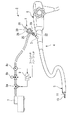
本発明の第一実施形態について図面を参照しながら詳細に説明する。図1は本実施形態における縫合器を含む内視鏡治療装置の概略図である。図2は縫合器の構成を示す断面図である。
【0012】
図1および図2に示すように、本実施形態の縫合器1は、内視鏡治療装置2の鉗子チャンネル3に挿入されて用いられる。内視鏡治療装置2は、縫合器1を内挿した内視鏡4と、縫合器1に流体である空気などの気体を供給する流体供給手段であるエアポンプ7とからなる。さらに、内視鏡4は、体腔内に導入され、その先端に鉗子チャンネル3、照明やカメラのレンズなどを有する導入部5と、導入部5を体腔外から操作する操作部6とからなる。
【0013】
図2に示すように縫合器1は、体腔内に挿入される軟性の挿入部10と、体腔外で施術者の操作を受け付ける手元操作部20とを有し、その内部に押出部材30を挿通させた構成になっている。
【0014】
挿入部10は、可撓管である外側シース11と、外側シース11に進退可能に収容された内側シース12と、内側シース12の先端に取り付けられた穿刺針13とを有する。穿刺針13は、先端を鋭角に傾斜させて鋭利な尖部とし、生体組織への穿通を容易にしている。また、穿刺針13は、先端の尖部に開口14を有する中空形状をなし、その内部に縫合糸15に取り付けられた係合部材16を収容する。穿刺針13および内側シース12には、係合部材16を穿刺針13の開口14から外に送り出すプッシャーである押出部材30が手元操作部20側から通されている。内側シース12および穿刺針13と押出部材30との間、ならびに、穿刺針13と係合部材16との間には、それぞれ所定のクリアランスが設けられている。これは、後に説明する流体の通流を可能にするためである。
【0015】
手元操作部20は、内側シース12に接続された操作部材21と、外側シース11に接続され、施術者が指を掛ける溝22aが形成されたノブを備える保持部材22と、押出部材30の把持用のノブ31とを有する。
操作部材21は、有底円筒形状を有し、開放されている端部21aが挿入部10の内側シース12の開放端12aに連通するように固定されており、底部に相当する端部21bには押出部材30を通す開口20cが形成されている。この開口20cの径は、円筒部分の内径よりも小さく、パッキン23を併用することで押出部材30の摺動を許容しつつ、保持部材21内の気密を保持している。また、円筒部分の側面には、図1に示すエアポンプ7から供給される気体を操作部材21内の空隙部分から構成される流体通路24に導入する際に用いる流体導入部である送気ポート25が取り付けられている。なお、端部21bには、円筒部分から突出し、施術者が指を掛けるリングが形成されたハンドル26を有している。
【0016】
押出部材30は、その一端が操作部材21から引き出され、把持用のノブ31が取り付けられている。また、その他端は、内側シース12の先端部分または穿刺針13に達している。この押出部材30は、操作部材21の開口20cおよびパッキン23に摺動可能に保持されており、操作部材21に対して引き出したり、押し込んだりすることができる。押出部材30が操作部材21に押し込まれると、その先端が係合部材16を穿刺針13から押し出すように押圧する。
【0017】
係合部材16は、円柱形状の部材からなり、その長手方向の中央付近に生体組織を縫合する縫合糸15の一端が係止されている。縫合時に係合部材16は、長手方向の広い面積で生体組織に当接し、生体組織に係合させられて、縫合糸15が生体組織から抜け落ちることを防止する。このような形状および機能から、係合部材16は、T状アンカーまたはTバーと呼ばれることもある。なお、図2において縫合糸15は、穿刺針13の内部から内側シース12を経て手元操作部20に至り、その後端から縫合器1の外に引き出されているが、縫合糸15は、穿刺針13の尖部の開口14から引き出され、外側シース11と内側シース12との間を通って、手元操作部20から外部に引き出されるようにしても良い。
【0018】
また、送気ポート25に気体を供給する送気機構について図1を用いて説明する。送気機構は、大気を吸引し、所定の圧力で吐出するエアポンプ7を有し、エアポンプ7の吐出側に、送気と排気とを選択する電磁弁8aと、送気する気体の流量を調整する流量調整弁8bと、実際に供給される気体の流量をモニタする流量計8cとをこの順番に配管で接続し、CPU(Central Processing Unit)9で必要な制御を行う構成になっている。CPU9は、送気開始や送気停止を切り替えるフットスイッチまたはハンドスイッチからの命令信号を受け付けたり、流量計8cをモニタしたりしながら、電磁弁8aの切り替えと流量調整弁8bの開度調整とを行う。なお、流量計8cと送気ポート25との間も配管で接続されている。
【0019】
次に、この縫合器1で、器官などの組織を縫合する手順について、腸などの管腔器官に穿刺する場合を例にして図1、図2、図3を用いて説明する。なお、図3は管腔器官に係合部材を留置するまでの手順を模式的に示した図である。図3に断面形状を示す管腔器官B1は、穿刺針13からみて手前側の生体組織B11と、奥側の生体組織B12とが密接するようにつぶれている。
【0020】
まず、図1の軟性内視鏡2と共に、図2に示す縫合器1の挿入部10を体腔内に導入する。このとき、手元操作部20の操作部材21が、保持部材22から所定量だけ引き出されているので、穿刺針13は外側シース11内に収容されている。穿刺針13内には、1つの係合部材16が収容されており、押出部材30は係合部材16を押圧しない待機位置まで後退している。
【0021】
この状態から操作部材21を保持部材22に向けて所定量だけ押し込んで、穿刺針13を外側シース11から露出させ、図3(a)に示すように、縫合を行う管腔器官B1に臨む位置まで移動させる。そして、図示しないフットスイッチまたはハンドスイッチをオンして、図1に示すエアポンプ7が吐出する気体を送気ポート25に供給する。このように送気ポート25に供給された気体は、図2に示す操作部材21の流体通路24を経て挿入部10の内側シース12に導入される。そして、押出部材30と内側シース12との間のクリアランスを通ると共に、押出部材30および係合部材16と、穿刺針13の内壁と間のクリアランスを通って、図3(a)の穿刺針13の先端の開口14から気体が噴き出す。
【0022】
さらに、操作部材21を押し込むと、穿刺針13が、その先端から気体を噴き出しながら管腔器官B1の手前側の生体組織B11の穿通する(図3(b))。穿刺針13の先端が生態組織B11を貫通すると、気体が生体組織B11と生体組織B12との間を離間させるように導入され、図3(c)に示すように管腔器官B1が膨らむ。所定量の気体を供給して、管腔器官B1が処置に必要な程度膨らんだと判断したら、図示しないフットスイッチまたはハンドスイッチをオフして、送気ポート25への気体の供給を停止する。これにより、管腔器官B1が膨らんで内部に空腔が形成されるので、さらに穿刺針13を押し込んでも、奥側の生体組織B12を穿刺することはない。なお、気体を噴出しないで行われる一般的な穿刺では、手前側の生体組織B11を穿通しても、管腔器官B1はつぶれたままであるので、生体組織B11と生体組織B12とが密着しているか、非常に近接しており、穿刺針13がそのまま奥側の生体組織B12まで穿刺してしまうことがある。
【0023】
気体を噴き込んで管腔器官B1を膨らませた状態で、図2の押出部材30の端部のノブ31を掴んで、これを操作部材21に向けて押し込む。すると、押出部材30の先端が、保持部材16を押圧して、穿刺針13の開口14から保持部材16を押し出す(図3(d))。保持部材16の押し出しを確認したら、押出部材30の押し込みを停止し、操作部材21を保持部材22から引き出す。操作部材21に接続された内側シース12および穿刺針13が相対的に引き出されることになるので、穿刺針13が管腔器官B1の生体組織B11から抜かれる。このとき、すでに穿刺針13から押し出され、離脱している係合部材16は、図3(e)に示すように、管腔器官B1内に留置され、係合部材16に取り付けられている縫合糸15が、穿刺針13の抜けた生体組織B11を貫通する。この縫合糸15を他の処置具などで引っ張っても、係合部材16がアンカー効果を果たすので、縫合糸15が管腔器官B1から抜けることはない。その後は、この縫合糸15を他の器官や生体組織に貫通させた他の縫合糸などに結び付ける。
【0024】
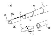
なお、係合部材16が穿刺針13内から脱落を防止するために、係合部材16を穿刺針13の内壁に摺動可能に接触させる場合には、係合部材16の断面を楕円形状とし、その長軸を穿刺針13の内径とほぼ等しくし、その短軸を穿刺針13の内径より小さくすれば、気体を通流させるクリアランスを確保することができる。また、穿刺針13の内径にほぼ等しい外径にする場合には、係合部材16の長さ方向に沿って溝を形成すると良い。さらに、穿刺針13の内径よりも径の小さい係合部材16を長さ方向に沿って湾曲させても良い。係合部材16およびその押出部材30は他の変形例について図4から図7を用いて以下に説明する。
【0025】
図4(a)の係合部材40は、外径が穿刺針13の内径にほぼ等しい中空のパイプの周方向の一部を窪ませて、窪み40aの中央付近に縫合糸15を取り付けた形状を有する。また、押出部材41も、外径が穿刺針13の内径にほぼ等しい中空の部材から構成している。このような係合部材40および押出部材41は、その中空部分を利用して気体を通流させることができる。
【0026】
図4(b)に示す係合部材43は、穿刺針13の内径にほぼ等しい幅を有する平板からなり、その中央部分に縫合糸15が取り付けられている。これに対する押出部材44は、係合部材43を確実に押圧するための2つのスリット44aが先端部分に形成されたパイプ形状を有する。この場合は、押出部材44の中空部分と、係合部材43と穿刺針13の内壁との間のクリアランスを利用して気体を通流させることができる。
【0027】
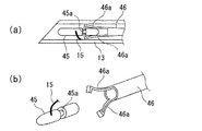
図5(a)、図5(b)に示す係合部材45は、穿刺針13の内径よりも小さい外径を有し、その長さ方向の中央部分に縫合糸15が取り付けられている。また、長さ方向における縫合糸15の取り付け位置と端部との間には、外径を減少させた縮径部分45aが形成されている。押出部材46は、中空のパイプの先端に、係合部材45の縮径部分45aを把持する2本の爪46aを有している。この爪46aは、弾性変形が可能であり、図5(a)に示すように、穿刺針13内では穿刺針13の内壁に押し付けられて閉じ、係合部材45の縮径部45aを把持する。一方、爪46aが穿刺針13から出ると、図5(b)に示すように開いて、係合部材45の把持を解除する。このため、穿刺針13内に収容された係合部材45は、気体の通流などにより穿刺針13から脱落することはないが、押出部材46により穿刺針13から押し出されたときは、容易に脱離することができる。この場合も、押出部材46の中空部分と、係合部材45と穿刺針13の内壁との間のクリアランスを利用して気体を通流させることができる。
【0028】
図6(a)、図6(b)に示す係合部材47は、穿刺針13の内径よりも小さい外径を有し、その長さ方向の中央部分に縫合糸15が取り付けられている。また、係合部材47は、その一部を反らせて、穿刺針13の内壁に当接するストッパ47aを形成している。このストッパ47aは、係合部材47のうち、最も径の太い部分となり、その太さは穿刺針13の内径以上である。したがって、ストッパ47aを押し戻すようにして穿刺針13内に係合部材47を収容すると、ストッパ47aにより係合部材47の移動が抑制される。このような係合部材47に好適な押出部材48は、穿刺針13の内径との間に所定のクリアランスを形成する中実のロッドである。この場合は、押出部材47および押出部材48と、穿刺針13の内壁との間のクリアランスを利用して気体を通流させることができる。
【0029】
図7(a)に示す係合部材49は、穿刺針13の外形と同程度の内径を有するパイプからなり、穿刺針13に外装して用いられる。縫合糸15は、係合部材49の長さ方向の中央付近に取り付けられている。この係合部材49に好適な押出部材50は、穿刺針13に外装されるパイプがあげられる。この保持部材49を留置する場合には、図7(b)に示すように、押出部材50を穿刺針13の外壁に沿って送って、穿刺針13の先端から係合部材49を押し出す。なお、気体の通流は、穿刺針13内を利用することができる。
【0030】
次に、本発明の第二実施形態について図面を参照しながら詳細に説明する。
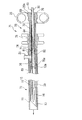
図8および図9は本実施形態における縫合器の構成を示す断面図である。なお、前記の第一実施形態と同一の構成要素は同じ符号を付し、詳細な説明の重複する部分は省略する。
図8に示す縫合器71は、内視鏡治療装置の鉗子チャンネルに挿入して使用されるもので、体腔内に導入される挿入部72と、施術者が操作する手元操作部73とを有している。
【0031】
挿入部72は、外側シース11と、外側シース11に内挿される内側シース12とを有し、内側シース12の先端には穿刺針13が取り付けられている。穿刺針13には、係合部材16が収容されており、係合部材16を押し出す押出部材30が手元操作部73側から挿入されている。なお、係合部材16は、前記第一実施形態における図4から図7の係合部材40,43,45,47,49であっても良い。
【0032】
手元操作部73は、外側シース11に接続された操作本体部74に、内側シース12に接続されて穿刺針13を進退させる針操作部75が所定のクリアランスを持って内装され、操作本体部74と針操作部75との間に送気を調整する流体封止部材76,77を介在させた構成になっている。
【0033】
操作本体部74は、円筒形を有すると共に、その円周面に施術者が指を掛ける溝部78が形成されている。この操作本体部74には、エアポンプから供給される流体である気体を操作本体部74内に導入するための送気ポート25が設けられている。
【0034】
針操作部75は、有底円筒形状を有し、開放されている端部75aが挿入部72の内側シース12の開放端12aに連通するように固定されており、底部に相当する端部75bには押出部材30を通す開口79が形成されている。この開口79の径は、円筒部分の内径よりも小さく、パッキン80を併用することで押出部材30の摺動を許容しつつ、気密を保持している。また、円筒部分の側面には、送気ポート25から操作本体部74内に導入された気体を、針操作部75の内部に導く通気孔81が設けられており、この通気孔81を介して気体を針操作部75の内部の空隙部分で構成される流体通路82に導入することで、これに連通する内側シース12および穿刺針13に気体が供給される。なお、端部75bには、円筒部分から突出し、施術者が指を掛けるリングが形成されたハンドル26を有している。
【0035】
また、針操作部75には、通気孔81を挟むように2本の溝(第一の溝83、第二の溝84)が円周に沿って形成されている。この溝83,84は、流体封止部材76,77の位置決め、および固定に用いられる。第一の溝83は、通気孔81よりも内側シース12側に形成されている。第二の溝84は、通気孔81よりもハンドル26側であって、後に説明する穿刺針13に押出量に応じた位置に形成されている。
【0036】
操作本体部74と針操作部75との間に介在する流体封止部材76,77は、第一の溝83に装着される第一のパッキン76と、第二の溝84に装着される第二のパッキン77からなる。第一のパッキン76および第二のパッキン77は、Oリングなどのリング状のシール部材で、針操作部75の溝83,84と操作本体部74の内壁とのそれぞれに隙間なく密接する。図8のように針操作部75が操作本体部74から引き出された状態、つまり2つのパッキン76,77の間に送気ポート25が位置する場合は、操作本体部74の内壁と針操作部75の外壁およびパッキン76,77で区画される空間の気密を保持し、この空間に導入される気体が通気孔81以外から流出することを防止する。また、図8に示すように、針操作部75が所定量だけ操作本体部74に押し込まれ、第二のパッキン77が送気ポート25の取り付け位置よりも挿入部72側に移動したときには、第二のパッキン77が送気ポート25から通気孔81への気体の通流を遮断する。
【0037】
次に、この縫合器71を用いた縫合処置について説明する。
まず、縫合器71を軟性内視鏡のチャンネルを利用して体腔内に導入し、図示しないフットスイッチまたはハンドスイッチを操作して、エアポンプからの気体を送気ポート25に供給する。このとき、送気ポート25に供給された気体は、操作本体部74の内壁と針操作部75の外壁およびパッキン76,77で区画される空間に導入され、通気孔81から針操作部75内部の流体通路82に流れ、これに連通する内側シース12内を通り、穿刺針13の開口14から噴き出す。
【0038】
この状態で、ハンドル26を持って針操作部75を押し込むと、穿刺針13が縫合対象となる生体組織に刺さる。このとき、針操作部75の移動に伴ってパッキン76,77が操作本体部74の内壁を摺動する。針操作部75およびパッキン76,77が移動しても、第二のパッキン77が送気ポート25の配設位置に達するまでは、通気孔81から穿刺針13に気体が供給され続けるので、穿刺針13からは気体が噴き出し続ける。
【0039】
さらに針操作部75が押し込まれると、穿刺針13が生体組織を貫通する。このときに穿刺針13から気体が噴き出しているので、穿通した生体組織が器官の一部である場合には、その器官が気体により膨らむ。
そして、穿刺針13が完全に生体組織を貫通したときには、気体の噴き出しが停止する。このときの針操作部75は、図9に示す位置まで押し込まれており、針操作部75と共に押し込まれる第二のパッキン77が送気ポート25の配設位置よりも生体組織側に移動しているためである。送気ポート25から導入される気体は、通気孔81には流れず、操作本体部74と針操作部75との隙間から外部に排気される。この後に、押出部材30を押し込んで、穿刺針13内の係合部材16を押し出して、係合部材16を留置させつつ、縫合糸15を生体組織に通す。穿刺針13を引き抜いてから、この縫合糸15を他の縫合糸などに結び付ける。
【0040】
このように、この縫合器71は、穿刺針13の先から気体を噴き出しながら生体組織を穿通するので、器官などを縫合する場合には器官を膨らませながら穿通することができる。また、穿刺針13の先端が、係合部材16の押し出しに充分な量だけ生体組織を貫通するときの穿刺針13の移動量、つまり針操作部75の押込量をあらかじめ調べ、その位置、もしくはその直前で、第二のパッキン77が送気ポート25を通過して、穿刺針13への気体の通流を遮断するように設定してあるので、穿通後は、器官が膨らみ過ぎないように気体の噴き出しを停止することができる。気体の噴き出しを停止する際の切り替えを穿刺針13の押し込みに伴って移動するパッキン76,77で行うようにしたので、適切なタイミングで確実に気体の噴き出しを停止できる。第一のパッキン76は、気体が外側シース11と内側シース12との間から体腔内に噴き出すことを防止する役割を有するが、流体封止部材としては、第二のパッキン77のみを使用しても良い。
【0041】
なお、本発明は前記の各実施形態に限定されずに広く応用することが可能である。
例えば、穿刺針13の先端から噴き出させる流体は、空気やその他の気体であっても良いが、生理食塩水などの液体であっても良い。
【0042】
また、図10(a)に示すように、穿刺針13内に複数の係合部材91を収容させても良い。各係合部材91は、円筒形状を有し、周方向の一部を、押出部材92の移動方向であるその長さ方向の中央付近を残して窪ませて、未加工の中央部分93と窪ませた部分94との間に、縫合糸15を挿通させる隙間を形成させている。隣り合う2つの係合部材91は、それぞれの隙間を挿通させた縫合糸15により連結され、穿刺針13内に収容される。係合部材91は、円筒形状による貫通孔95が連なった形態で収容されるので、送気ポート25(図2参照)から送られてくる気体を、その貫通孔95を通じて穿刺針13の先端の開口14から噴き出させることができる。このように貫通孔95を有する係合部材91に好適な押出部材92は、パイプ形状でその内部に気体を通流させる貫通孔96を有するものが良い。押出部材92への気体の導入は、操作本体部21,75の流体通路24,82と連通する孔を設けることで実現できる。
【0043】
このように連続させて収容された係合部材91を利用して縫合処置を行うときには、手元操作部20,73で押出部材92を押し込む。この押出部材92は、一番奥に収容されている係合部材91を押圧し、隣の係合部材91を穿刺針13の開口14に向けて押す。その他の係合部材91は、押出部材92側に位置する他の係合部材92に押されるようにして穿刺針13の開口14に向けて押される。そして、穿刺針13の開口14に近い係合部材91から順番に、穿刺針13から器官内に押し出される。例えば、図10(b)に模式的に示すように、2つの生体組織を縫合する場合に、係合部材91は、穿刺針13が穿通した2つ目の生体組織側に留置される。この状態で縫合糸15を引っ張ると、縫合糸15を挿通させた未加工部分92が生体組織に当接するように引っ張られるので、生体組織と係合部材91との間に大きな接触面積を確保できる。同様にして残りの係合部材91も、所定の間隔を置いて、2つ目の生体組織に大きな接触面積で当接させることができる。
【0044】
【発明の効果】
以上説明したように、請求項1に係る発明によれば、流体を噴き出させ、器官などを膨らませながら生体組織に穿刺針を通すことができるので、縫合対象のみを確実に穿通し、縫合処置を行うことが可能になる。
請求項2に係る発明によれば、係合部材を穿刺針内に収容した状態で流体の通路を確保できるので、生体組織に穿刺しながら流体を噴き出させることが可能になる。
請求項3に係る発明によれば、穿刺針が所定量だけ移動するまでの間は流体が供給されるが、所定量を超えたら流体導入部と流体通路との連通が遮断されるので、器官などを適度に膨らませることができる。
【図面の簡単な説明】
【図1】 本発明の縫合器を含む内視鏡治療装置の概略図である。
【図2】 縫合器の構成を示す断面図である。
【図3】 管腔器官に係合部材を留置するまでの手順を模式的に示した図である。
【図4】 係合部材と押出部材の変形例を示す斜視図である。
【図5】 係合部材と押出部材の変形例を示す(a)断面図、(b)斜視図である。
【図6】 係合部材と押出部材の変形例を示す(a)断面図、(b)斜視図である。
【図7】 係合部材と押出部材の変形例を示す斜視図である。
【図8】 縫合器の構成を示す断面図である。
【図9】 縫合器の構成を示す断面図である。
【図10】 係合部材と押出部材の変形例を示す斜視図である。
【符号の説明】
1 縫合器
10 挿入部
13 穿刺針
15 縫合糸
16 係合部材
20 手元操作部
21 操作部材
24 流体通路
25 送気ポート(流体導入部)
30 押出部材
71 縫合器
72 挿入部
73 手元操作部(操作部)
74 操作本体部(本体部)
75 針操作部
76 第一のパッキン(流体封止部材)
77 第二のパッキン(流体封止部材)
81 通気孔
82 流体通路[0001]
BACKGROUND OF THE INVENTION
The present invention relates to a suture instrument introduced into a body cavity through a channel of an endoscope.
[0002]
[Prior art]
Conventionally, a technique for introducing a treatment device into a body cavity and performing a necessary treatment is known. As an apparatus used for this kind of treatment, there is an apparatus for suturing tissue by pushing out an engaging member attached with a suture accommodated in a puncture needle provided at a distal end portion of a catheter with a pushing member out of the catheter. Yes (see, for example, Patent Document 1). Here, the intracardiac suture surgical tool described in Patent Document 1 is attached to the sheath so that the puncture cartel can be inserted and removed freely, and physiological saline for preventing blood coagulation is injected from the side injection tube into the puncture catheter. It can be configured.
[0003]
[Patent Document 1]
Japanese Patent No. 3134288 (paragraph numbers 0007 and 0010, FIG. 4)
[0004]
[Problems to be solved by the invention]
By the way, when a biological tissue to be sutured is close to another biological tissue, such as when intestine or a tubular organ is sutured, a puncture needle that penetrates the biological tissue to be sutured penetrates the other biological tissue. There is a problem that it has to be operated carefully because there is a possibility of being damaged.
The present invention solves such a problem, and an object of the present invention is to provide a suturing device capable of reliably puncturing only a suture object and indwelling an engaging member.
[0005]
[Means for Solving the Problems]
In order to achieve the above object, the present invention provides the following means.
The invention according to claim 1 includes a hollow puncture needle having an opening formed at a tip thereof, and includes an insertion portion that is introduced into a body cavity, and an operation portion that operates a push member passed through the insertion portion. A suturing device that pushes the engaging member attached to the suture from the distal end of the puncture needle with the push-out member and passes the suture through the living tissue while placing the engaging member in the living tissue; A gas provided to be connected to the puncture needle, for sending a predetermined amount of gas to the puncture needle and ejecting the gas from the puncture needle, and separating the tissue in front of the puncture needle from the puncture needle An introduction part and an inside of the puncture needle in a state where the engagement member can be pushed out from the puncture needle The gas Let through aisle Are provided.
[0006]
When the suture device according to the present invention penetrates a suture target with a puncture needle, gas Introduced from the introduction gas The aisle It is possible to supply to the puncture needle via. For this reason, gas The puncture needle can be passed through the living tissue while spouting out the organ, and the organ or the like can be inflated at the time of penetration.
[0007]
According to a second aspect of the present invention, in the suturing device according to the first aspect, the engaging member is formed in a cylindrical shape, and the space is formed in the space inside the engaging member. gas It is characterized by allowing flow through.
[0008]
When the suturing device according to the present invention is accommodated in the inside of the puncture needle, gas By letting through gas Secure the passageway from the tip of the puncture needle gas It becomes possible to spout
[0009]
The invention according to
[0010]
The suturing device according to the present invention comprises: gas After the sealing member has moved by a predetermined amount gas It is attached at a position to stop the supply. Therefore, until the puncture needle moves by a predetermined amount gas Is supplied, but if it exceeds the specified amount gas With the introduction aisle Communication with is interrupted.
[0011]
DETAILED DESCRIPTION OF THE INVENTION
A first embodiment of the present invention will be described in detail with reference to the drawings. FIG. 1 is a schematic view of an endoscopic treatment apparatus including a suture instrument in the present embodiment. FIG. 2 is a cross-sectional view showing the configuration of the suture instrument.
[0012]
As shown in FIGS. 1 and 2, the suturing device 1 of the present embodiment is used by being inserted into the
[0013]
As shown in FIG. 2, the suture instrument 1 has a
[0014]
The
[0015]
The
The
[0016]
One end of the pushing
[0017]
The engaging
[0018]
An air supply mechanism for supplying gas to the
[0019]
Next, a procedure for suturing a tissue such as an organ with the suturing device 1 will be described with reference to FIGS. 1, 2, and 3 by taking as an example a case of puncturing a hollow organ such as an intestine. FIG. 3 is a diagram schematically showing a procedure until the engaging member is placed in the luminal organ. The luminal organ B1 having a cross-sectional shape shown in FIG. 3 is collapsed so that the living tissue B11 on the near side and the living tissue B12 on the far side as viewed from the
[0020]
First, together with the flexible endoscope 2 of FIG. 1, the
[0021]
From this state, the operating
[0022]
Further, when the
[0023]
In a state where the gas is blown and the luminal organ B1 is inflated, the
[0024]
When the
[0025]
The
[0026]
The
[0027]
The
[0028]
The
[0029]
The
[0030]
Next, a second embodiment of the present invention will be described in detail with reference to the drawings.
8 and 9 are cross-sectional views showing the configuration of the suturing device in this embodiment. Note that the same components as those in the first embodiment are denoted by the same reference numerals, and the detailed description thereof is omitted.
A
[0031]
The
[0032]
The
[0033]
The operation
[0034]
The
[0035]
Further, the
[0036]
The
[0037]
Next, a suturing procedure using the
First, the
[0038]
In this state, when the
[0039]
When the
When the
[0040]
As described above, the
[0041]
The present invention is not limited to the above embodiments and can be widely applied.
For example, the fluid ejected from the tip of the
[0042]
Further, as shown in FIG. 10A, a plurality of engaging
[0043]
When the suturing treatment is performed by using the engaging
[0044]
【The invention's effect】
As described above, according to the invention according to claim 1, since the puncture needle can be passed through the living tissue while injecting the fluid and inflating the organ or the like, only the suture target is securely penetrated, and the suture treatment is performed. It becomes possible to do.
According to the second aspect of the present invention, the fluid passage can be secured in a state where the engaging member is accommodated in the puncture needle, so that the fluid can be ejected while puncturing the living tissue.
According to the third aspect of the present invention, fluid is supplied until the puncture needle moves by a predetermined amount, but if the predetermined amount is exceeded, the communication between the fluid introduction part and the fluid passage is interrupted. Etc. can be inflated moderately.
[Brief description of the drawings]
FIG. 1 is a schematic view of an endoscopic treatment apparatus including a suture instrument of the present invention.
FIG. 2 is a cross-sectional view showing a configuration of a suturing device.
FIG. 3 is a diagram schematically showing a procedure until an engaging member is placed in a luminal organ.
FIG. 4 is a perspective view showing a modification of the engaging member and the pushing member.
FIGS. 5A and 5B are a sectional view and a perspective view showing a modified example of an engaging member and a pushing member. FIGS.
6A is a cross-sectional view showing a modified example of the engaging member and the pushing member, and FIG. 6B is a perspective view.
FIG. 7 is a perspective view showing a modification of the engaging member and the pushing member.
FIG. 8 is a cross-sectional view showing the configuration of the suturing device.
FIG. 9 is a cross-sectional view showing the configuration of the suture instrument.
FIG. 10 is a perspective view showing a modification of the engaging member and the pushing member.
[Explanation of symbols]
1 Suture device
10 Insertion part
13 Puncture needle
15 Suture
16 Engagement member
20 Hand control unit
21 Operation members
24 Fluid passage
25 Air supply port (fluid introduction part)
30 Extruded member
71 Suture
72 Insertion part
73 Hand control unit (control unit)
74 Operation body (main body)
75 Needle operation unit
76 First packing (fluid sealing member)
77 Second packing (fluid sealing member)
81 Vent
82 Fluid passage
Claims (3)
前記穿刺針と接続されて設けられ、前記穿刺針に所定量の気体を送り込んで前記穿刺針から噴出させ、前記穿刺針の前方の組織を前記穿刺針から離間させるための気体導入部と、前記穿刺針から前記係合部材を押し出し可能に配置した状態で前記穿刺針の内部に前記気体を通流させる通路とを備えることを特徴とする縫合器。A hollow puncture needle having an opening formed at the tip, an insertion portion that is introduced into a body cavity, and an operation portion that operates an extrusion member that is passed through the insertion portion, and is attached to a suture thread In the suturing device for passing the suture through the living tissue while pushing the joint member from the distal end of the puncture needle with the pushing member and placing the engaging member in the living tissue,
A gas introduction part provided to be connected to the puncture needle, for sending a predetermined amount of gas into the puncture needle and ejecting the gas from the puncture needle, and separating the tissue in front of the puncture needle from the puncture needle ; suturing device, characterized in that in a state of being disposed to be extruded the engaging member from the puncture needle and a passage for flow through the gas in the interior of the biopsy needle.
Priority Applications (6)
| Application Number | Priority Date | Filing Date | Title |
|---|---|---|---|
| JP2003162008A JP4145200B2 (en) | 2003-06-06 | 2003-06-06 | Suture device |
| EP04013050A EP1484021B1 (en) | 2003-06-06 | 2004-06-02 | Medical Suturing Instrument |
| US10/861,806 US20040249395A1 (en) | 2003-06-06 | 2004-06-04 | Suturing instrument |
| US11/639,708 US20070100376A1 (en) | 2003-06-06 | 2006-12-15 | Suturing instrument |
| US11/639,705 US20070100375A1 (en) | 2003-06-06 | 2006-12-15 | Suturing instrument |
| US11/833,729 US20070276424A1 (en) | 2003-06-06 | 2007-08-03 | Suturing instrument |
Applications Claiming Priority (1)
| Application Number | Priority Date | Filing Date | Title |
|---|---|---|---|
| JP2003162008A JP4145200B2 (en) | 2003-06-06 | 2003-06-06 | Suture device |
Publications (2)
| Publication Number | Publication Date |
|---|---|
| JP2004358045A JP2004358045A (en) | 2004-12-24 |
| JP4145200B2 true JP4145200B2 (en) | 2008-09-03 |
Family
ID=33157214
Family Applications (1)
| Application Number | Title | Priority Date | Filing Date |
|---|---|---|---|
| JP2003162008A Expired - Fee Related JP4145200B2 (en) | 2003-06-06 | 2003-06-06 | Suture device |
Country Status (3)
| Country | Link |
|---|---|
| US (4) | US20040249395A1 (en) |
| EP (1) | EP1484021B1 (en) |
| JP (1) | JP4145200B2 (en) |
Families Citing this family (195)
| Publication number | Priority date | Publication date | Assignee | Title |
|---|---|---|---|---|
| US7416554B2 (en) | 2002-12-11 | 2008-08-26 | Usgi Medical Inc | Apparatus and methods for forming and securing gastrointestinal tissue folds |
| US7637905B2 (en) | 2003-01-15 | 2009-12-29 | Usgi Medical, Inc. | Endoluminal tool deployment system |
| US7160312B2 (en) * | 1999-06-25 | 2007-01-09 | Usgi Medical, Inc. | Implantable artificial partition and methods of use |
| US7618426B2 (en) | 2002-12-11 | 2009-11-17 | Usgi Medical, Inc. | Apparatus and methods for forming gastrointestinal tissue approximations |
| US7955340B2 (en) | 1999-06-25 | 2011-06-07 | Usgi Medical, Inc. | Apparatus and methods for forming and securing gastrointestinal tissue folds |
| GB2387040B (en) * | 2002-03-28 | 2004-03-10 | Wheeler & Clinch Ltd | A contact |
| US7942884B2 (en) | 2002-12-11 | 2011-05-17 | Usgi Medical, Inc. | Methods for reduction of a gastric lumen |
| US7942898B2 (en) | 2002-12-11 | 2011-05-17 | Usgi Medical, Inc. | Delivery systems and methods for gastric reduction |
| US8308765B2 (en) | 2004-05-07 | 2012-11-13 | Usgi Medical, Inc. | Apparatus and methods for positioning and securing anchors |
| US8216252B2 (en) | 2004-05-07 | 2012-07-10 | Usgi Medical, Inc. | Tissue manipulation and securement system |
| TW200506345A (en) * | 2003-08-14 | 2005-02-16 | Au Optronics Corp | Water quality analysis method using potassium permanganate |
| US7736372B2 (en) * | 2003-11-13 | 2010-06-15 | Usgi Medical, Inc. | Apparatus and methods for endoscopic suturing |
| US7347863B2 (en) | 2004-05-07 | 2008-03-25 | Usgi Medical, Inc. | Apparatus and methods for manipulating and securing tissue |
| US20050251189A1 (en) | 2004-05-07 | 2005-11-10 | Usgi Medical Inc. | Multi-position tissue manipulation assembly |
| US7361180B2 (en) | 2004-05-07 | 2008-04-22 | Usgi Medical, Inc. | Apparatus for manipulating and securing tissue |
| JP4212494B2 (en) * | 2004-03-02 | 2009-01-21 | 日本シャーウッド株式会社 | Medical suture tool |
| US8257394B2 (en) | 2004-05-07 | 2012-09-04 | Usgi Medical, Inc. | Apparatus and methods for positioning and securing anchors |
| US20050251159A1 (en) * | 2004-05-07 | 2005-11-10 | Usgi Medical Inc. | Methods and apparatus for grasping and cinching tissue anchors |
| US7736374B2 (en) | 2004-05-07 | 2010-06-15 | Usgi Medical, Inc. | Tissue manipulation and securement system |
| US8444657B2 (en) | 2004-05-07 | 2013-05-21 | Usgi Medical, Inc. | Apparatus and methods for rapid deployment of tissue anchors |
| US7918869B2 (en) | 2004-05-07 | 2011-04-05 | Usgi Medical, Inc. | Methods and apparatus for performing endoluminal gastroplasty |
| US7695493B2 (en) | 2004-06-09 | 2010-04-13 | Usgi Medical, Inc. | System for optimizing anchoring force |
| JP2006102255A (en) * | 2004-10-06 | 2006-04-20 | Nippon Sherwood Medical Industries Ltd | Connecting structure of infusion line and connector with the connecting structure |
| JP4669315B2 (en) * | 2005-04-21 | 2011-04-13 | 日本シャーウッド株式会社 | Organ fixture and organ fixture set |
| ES2590252T3 (en) | 2005-02-07 | 2016-11-21 | Ivy Sports Medicine, Llc. | System for fixing a completely internal suture for joining an implant and repairing a soft tissue |
| US8128640B2 (en) | 2005-02-07 | 2012-03-06 | Ivy Sports Medicine LLC | System and method for all-inside suture fixation for implant attachment and soft tissue repair |
| JP5058154B2 (en) * | 2005-04-20 | 2012-10-24 | アースロスコピック イノベーションズ エルエルシー | Method and apparatus for attaching a suture |
| US7833244B2 (en) * | 2005-04-20 | 2010-11-16 | Arthroscopic Innovations Llc | Suture fixation device and method for surgical repair |
| US8333777B2 (en) | 2005-04-22 | 2012-12-18 | Benvenue Medical, Inc. | Catheter-based tissue remodeling devices and methods |
| US20060253130A1 (en) * | 2005-05-03 | 2006-11-09 | Esophyx, Inc. | Tissue fixation assemblies having a plurality of fasteners ready for serial deployment |
| US8298291B2 (en) | 2005-05-26 | 2012-10-30 | Usgi Medical, Inc. | Methods and apparatus for securing and deploying tissue anchors |
| US9585651B2 (en) | 2005-05-26 | 2017-03-07 | Usgi Medical, Inc. | Methods and apparatus for securing and deploying tissue anchors |
| US20070005080A1 (en) * | 2005-06-29 | 2007-01-04 | Esophyx, Inc. | Bolt action fastener delivery assembly |
| US8906040B2 (en) | 2005-07-13 | 2014-12-09 | Creighton University | Systems and techniques for minimally invasive gastrointestinal procedures |
| US8641729B2 (en) * | 2005-07-13 | 2014-02-04 | Creighton University | Systems and techniques for minimally invasive gastrointestinal procedures |
| EP1749481A1 (en) * | 2005-08-02 | 2007-02-07 | Marco Gandini | Suture device |
| JP4488981B2 (en) * | 2005-08-23 | 2010-06-23 | 日本シャーウッド株式会社 | Extractor and medical suture tool set |
| US7875041B2 (en) | 2005-09-28 | 2011-01-25 | Olympus Medical Systems Corp. | Suturing method for penetrating hole |
| JP4614451B2 (en) * | 2005-12-26 | 2011-01-19 | 日本シャーウッド株式会社 | Medical suture tool |
| US8726909B2 (en) | 2006-01-27 | 2014-05-20 | Usgi Medical, Inc. | Methods and apparatus for revision of obesity procedures |
| ES2382813T3 (en) | 2006-04-28 | 2012-06-13 | Covidien Ag | Instrumental set for organopexy |
| US8105355B2 (en) | 2006-05-18 | 2012-01-31 | C.R. Bard, Inc. | Suture lock fastening device |
| US7758598B2 (en) | 2006-05-19 | 2010-07-20 | Ethicon Endo-Surgery, Inc. | Combination knotting element and suture anchor applicator |
| US7918868B2 (en) | 2006-05-22 | 2011-04-05 | Scandius Biomendical, Inc. | Method and apparatus for meniscal repair |
| US8876842B2 (en) | 2006-05-22 | 2014-11-04 | Covidien Lp | Meniscal repair device |
| EP1862125B1 (en) * | 2006-05-31 | 2011-08-03 | Covidien AG | Medical suturing tool with gripping device |
| US8870916B2 (en) | 2006-07-07 | 2014-10-28 | USGI Medical, Inc | Low profile tissue anchors, tissue anchor systems, and methods for their delivery and use |
| US7674275B2 (en) | 2006-10-05 | 2010-03-09 | Ethicon Endo-Surgery, Inc. | Suture anchor |
| JP4536698B2 (en) * | 2006-10-05 | 2010-09-01 | 日本シャーウッド株式会社 | Medical suture tool |
| US20080103527A1 (en) * | 2006-10-27 | 2008-05-01 | Martin David T | Flexible endoscopic suture anchor applier |
| EP2094167B1 (en) * | 2006-11-30 | 2011-06-29 | Wilson-Cook Medical, Inc. | Visceral anchors for purse-string closure of perforations |
| JP2008148933A (en) * | 2006-12-18 | 2008-07-03 | Yoshikawa Kasei Kk | Placement device of internal organ fixing appliance |
| US7655004B2 (en) | 2007-02-15 | 2010-02-02 | Ethicon Endo-Surgery, Inc. | Electroporation ablation apparatus, system, and method |
| JP4565576B2 (en) | 2007-02-20 | 2010-10-20 | 日本シャーウッド株式会社 | Puncture needle assist tool |
| US8128657B2 (en) * | 2007-02-27 | 2012-03-06 | Olympus Medical Systems Corp. | Suture instrument |
| US8308766B2 (en) * | 2007-02-27 | 2012-11-13 | Olympus Medical Systems Corp. | Endoscopic treatment instrument |
| ATE514386T1 (en) | 2007-02-28 | 2011-07-15 | Wilson Cook Medical Inc | INTESTINAL BYPASS USING MAGNETS |
| US7815662B2 (en) | 2007-03-08 | 2010-10-19 | Ethicon Endo-Surgery, Inc. | Surgical suture anchors and deployment device |
| US8075572B2 (en) | 2007-04-26 | 2011-12-13 | Ethicon Endo-Surgery, Inc. | Surgical suturing apparatus |
| US8100922B2 (en) | 2007-04-27 | 2012-01-24 | Ethicon Endo-Surgery, Inc. | Curved needle suturing tool |
| US20080275476A1 (en) | 2007-05-04 | 2008-11-06 | Cropper Michael S | Threader for knotting element |
| US7875042B2 (en) | 2007-05-04 | 2011-01-25 | Ethicon Endo-Surgery, Inc. | Suture anchor loader |
| AU2008256823B2 (en) * | 2007-05-25 | 2013-09-12 | Cook Medical Technologies Llc | Medical devices, systems and methods for closing perforations |
| US8740937B2 (en) | 2007-05-31 | 2014-06-03 | Cook Medical Technologies Llc | Suture lock |
| US20110106113A1 (en) * | 2007-07-13 | 2011-05-05 | The Brigham And Women's Hospital, Inc. | System and method for hernia mesh fixation |
| CA2696576C (en) * | 2007-08-17 | 2012-09-11 | Wilson-Cook Medical Inc. | Device to open and close a bodily wall |
| US8579897B2 (en) | 2007-11-21 | 2013-11-12 | Ethicon Endo-Surgery, Inc. | Bipolar forceps |
| US8262655B2 (en) | 2007-11-21 | 2012-09-11 | Ethicon Endo-Surgery, Inc. | Bipolar forceps |
| US8568410B2 (en) | 2007-08-31 | 2013-10-29 | Ethicon Endo-Surgery, Inc. | Electrical ablation surgical instruments |
| US9339265B2 (en) * | 2007-09-25 | 2016-05-17 | Cook Medical Technologies Llc | Medical devices, systems, and methods for using tissue anchors |
| US8771314B2 (en) | 2007-09-28 | 2014-07-08 | Ethicon, Inc. | Surgical anchor device |
| US20090112059A1 (en) | 2007-10-31 | 2009-04-30 | Nobis Rudolph H | Apparatus and methods for closing a gastrotomy |
| US8480657B2 (en) | 2007-10-31 | 2013-07-09 | Ethicon Endo-Surgery, Inc. | Detachable distal overtube section and methods for forming a sealable opening in the wall of an organ |
| AU2009204417B2 (en) * | 2008-01-03 | 2013-05-09 | Cook Medical Technologies Llc | Medical systems and devices for endoscopically suturing perforations |
| US8961538B2 (en) | 2008-03-04 | 2015-02-24 | Arthrex, Inc. | Method and system for meniscal repair using suture implant cinch construct |
| US8262680B2 (en) | 2008-03-10 | 2012-09-11 | Ethicon Endo-Surgery, Inc. | Anastomotic device |
| EP2285294A1 (en) * | 2008-04-23 | 2011-02-23 | Wilson-Cook Medical Inc. | Tacking device |
| US20090287045A1 (en) * | 2008-05-15 | 2009-11-19 | Vladimir Mitelberg | Access Systems and Methods of Intra-Abdominal Surgery |
| US8771260B2 (en) | 2008-05-30 | 2014-07-08 | Ethicon Endo-Surgery, Inc. | Actuating and articulating surgical device |
| US8114072B2 (en) | 2008-05-30 | 2012-02-14 | Ethicon Endo-Surgery, Inc. | Electrical ablation device |
| US8679003B2 (en) | 2008-05-30 | 2014-03-25 | Ethicon Endo-Surgery, Inc. | Surgical device and endoscope including same |
| US8070759B2 (en) | 2008-05-30 | 2011-12-06 | Ethicon Endo-Surgery, Inc. | Surgical fastening device |
| US8317806B2 (en) | 2008-05-30 | 2012-11-27 | Ethicon Endo-Surgery, Inc. | Endoscopic suturing tension controlling and indication devices |
| US8652150B2 (en) | 2008-05-30 | 2014-02-18 | Ethicon Endo-Surgery, Inc. | Multifunction surgical device |
| US8906035B2 (en) | 2008-06-04 | 2014-12-09 | Ethicon Endo-Surgery, Inc. | Endoscopic drop off bag |
| US8403926B2 (en) | 2008-06-05 | 2013-03-26 | Ethicon Endo-Surgery, Inc. | Manually articulating devices |
| JP5185706B2 (en) * | 2008-06-24 | 2013-04-17 | 日本コヴィディエン株式会社 | Puncture needle assist tool |
| US8361112B2 (en) | 2008-06-27 | 2013-01-29 | Ethicon Endo-Surgery, Inc. | Surgical suture arrangement |
| US8262563B2 (en) | 2008-07-14 | 2012-09-11 | Ethicon Endo-Surgery, Inc. | Endoscopic translumenal articulatable steerable overtube |
| US8888792B2 (en) | 2008-07-14 | 2014-11-18 | Ethicon Endo-Surgery, Inc. | Tissue apposition clip application devices and methods |
| US20100023025A1 (en) * | 2008-07-25 | 2010-01-28 | Zeiner Mark S | Reloadable laparoscopic fastener deploying device with disposable cartridge for use in a gastric volume reduction procedure |
| US20100023026A1 (en) * | 2008-07-25 | 2010-01-28 | Zeiner Mark S | Reloadable laparoscopic fastener deploying device with disposable cartridge for use in a gastric volume reduction procedure |
| US20100023022A1 (en) * | 2008-07-25 | 2010-01-28 | Zeiner Mark S | Reloadable laparoscopic fastener deploying device with disposable cartridge use in a gastric volume reduction procedure |
| US20100023024A1 (en) * | 2008-07-25 | 2010-01-28 | Zeiner Mark S | Reloadable laparoscopic fastener deploying device with disposable cartridge for use in a gastric volume reduction procedure |
| US8911454B2 (en) * | 2008-07-31 | 2014-12-16 | Olympus Medical Systems Corp. | Suturing device |
| US8863748B2 (en) * | 2008-07-31 | 2014-10-21 | Olympus Medical Systems Corp. | Endoscopic surgical operation method |
| US8211125B2 (en) | 2008-08-15 | 2012-07-03 | Ethicon Endo-Surgery, Inc. | Sterile appliance delivery device for endoscopic procedures |
| CA2733933C (en) | 2008-08-19 | 2014-03-11 | Wilson-Cook Medical Inc. | Apparatus for removing lymph nodes or anchoring into tissue during a translumenal procedure |
| US8529563B2 (en) | 2008-08-25 | 2013-09-10 | Ethicon Endo-Surgery, Inc. | Electrical ablation devices |
| US8241204B2 (en) | 2008-08-29 | 2012-08-14 | Ethicon Endo-Surgery, Inc. | Articulating end cap |
| US8480689B2 (en) | 2008-09-02 | 2013-07-09 | Ethicon Endo-Surgery, Inc. | Suturing device |
| US8409200B2 (en) | 2008-09-03 | 2013-04-02 | Ethicon Endo-Surgery, Inc. | Surgical grasping device |
| US8114119B2 (en) | 2008-09-09 | 2012-02-14 | Ethicon Endo-Surgery, Inc. | Surgical grasping device |
| US8192461B2 (en) | 2008-09-11 | 2012-06-05 | Cook Medical Technologies Llc | Methods for facilitating closure of a bodily opening using one or more tacking devices |
| US9332973B2 (en) | 2008-10-01 | 2016-05-10 | Covidien Lp | Needle biopsy device with exchangeable needle and integrated needle protection |
| US20110190662A1 (en) * | 2008-10-01 | 2011-08-04 | Beacon Endoscopic Corporation | Rapid exchange fna biopsy device with diagnostic and therapeutic capabilities |
| US9186128B2 (en) | 2008-10-01 | 2015-11-17 | Covidien Lp | Needle biopsy device |
| US8337394B2 (en) | 2008-10-01 | 2012-12-25 | Ethicon Endo-Surgery, Inc. | Overtube with expandable tip |
| US11298113B2 (en) | 2008-10-01 | 2022-04-12 | Covidien Lp | Device for needle biopsy with integrated needle protection |
| US9782565B2 (en) | 2008-10-01 | 2017-10-10 | Covidien Lp | Endoscopic ultrasound-guided biliary access system |
| US8968210B2 (en) | 2008-10-01 | 2015-03-03 | Covidien LLP | Device for needle biopsy with integrated needle protection |
| EP2346411B1 (en) * | 2008-10-06 | 2013-10-02 | Cook Medical Technologies LLC | Endcap for safely deploying tissue anchors |
| BRPI0921919A2 (en) | 2008-11-11 | 2017-05-30 | Univ Texas | medical devices, devices, systems and methods |
| US8157834B2 (en) | 2008-11-25 | 2012-04-17 | Ethicon Endo-Surgery, Inc. | Rotational coupling device for surgical instrument with flexible actuators |
| CA2747172C (en) | 2008-12-05 | 2015-04-14 | Vihar C. Surti | Tissue anchors for purse-string closure of perforations |
| JP5724134B2 (en) | 2008-12-09 | 2015-05-27 | クック・メディカル・テクノロジーズ・リミテッド・ライアビリティ・カンパニーCook Medical Technologies Llc | Retractable anchoring device |
| US8172772B2 (en) | 2008-12-11 | 2012-05-08 | Ethicon Endo-Surgery, Inc. | Specimen retrieval device |
| WO2010080386A2 (en) | 2008-12-19 | 2010-07-15 | Wilson-Cook Medical Inc. | Clip devices and methods of delivery and deployment |
| US8828031B2 (en) | 2009-01-12 | 2014-09-09 | Ethicon Endo-Surgery, Inc. | Apparatus for forming an anastomosis |
| US8361066B2 (en) | 2009-01-12 | 2013-01-29 | Ethicon Endo-Surgery, Inc. | Electrical ablation devices |
| BRPI1007339A2 (en) | 2009-01-16 | 2017-07-25 | Univ Texas | MEDICAL DEVICES AND METHODS |
| JP5219855B2 (en) * | 2009-01-27 | 2013-06-26 | Hoya株式会社 | Endoscopic suture device |
| US9226772B2 (en) | 2009-01-30 | 2016-01-05 | Ethicon Endo-Surgery, Inc. | Surgical device |
| US8252057B2 (en) | 2009-01-30 | 2012-08-28 | Ethicon Endo-Surgery, Inc. | Surgical access device |
| US8037591B2 (en) | 2009-02-02 | 2011-10-18 | Ethicon Endo-Surgery, Inc. | Surgical scissors |
| AU2010232485B2 (en) * | 2009-04-03 | 2013-11-07 | Cook Medical Technologies Llc | Medical devices, systems, and methods for rapid deployment and fixation of tissue anchors |
| WO2010115072A1 (en) | 2009-04-03 | 2010-10-07 | Wilson-Cook Medical, Inc. | Tissue anchors and medical devices for rapid deployment of tissue anchors |
| WO2010127083A2 (en) * | 2009-04-30 | 2010-11-04 | Mayo Foundation For Medical Education And Research | Body lumen occlusion apparatus and methods |
| WO2010127084A1 (en) | 2009-05-01 | 2010-11-04 | Wilson-Cook Medical, Inc. | Medical systems, devices and methods for suturing perforations |
| JP2012527970A (en) | 2009-05-28 | 2012-11-12 | クック メディカル テクノロジーズ エルエルシー | Hail-fastening device and hail-fastening device deployment method |
| AU2010263224B2 (en) | 2009-06-26 | 2014-02-06 | Cook Medical Technologies Llc | Linear clamps for anastomosis |
| EP2452631B1 (en) * | 2009-07-10 | 2018-03-07 | Educational Foundation Jichi Medical University | Surgical system for stoma closure in biological duct |
| US8979873B2 (en) | 2009-09-22 | 2015-03-17 | DePuy Synthes Products, LLC | Multi-stitch anchor suture-based soft tissue repair system |
| US10172669B2 (en) | 2009-10-09 | 2019-01-08 | Ethicon Llc | Surgical instrument comprising an energy trigger lockout |
| US20110098704A1 (en) | 2009-10-28 | 2011-04-28 | Ethicon Endo-Surgery, Inc. | Electrical ablation devices |
| EP2496148B1 (en) | 2009-11-03 | 2013-11-20 | Cook Medical Technologies LLC | Planar clamps for anastomosis |
| US8608652B2 (en) | 2009-11-05 | 2013-12-17 | Ethicon Endo-Surgery, Inc. | Vaginal entry surgical devices, kit, system, and method |
| US8353487B2 (en) | 2009-12-17 | 2013-01-15 | Ethicon Endo-Surgery, Inc. | User interface support devices for endoscopic surgical instruments |
| US8496574B2 (en) | 2009-12-17 | 2013-07-30 | Ethicon Endo-Surgery, Inc. | Selectively positionable camera for surgical guide tube assembly |
| US9028483B2 (en) | 2009-12-18 | 2015-05-12 | Ethicon Endo-Surgery, Inc. | Surgical instrument comprising an electrode |
| US8506564B2 (en) | 2009-12-18 | 2013-08-13 | Ethicon Endo-Surgery, Inc. | Surgical instrument comprising an electrode |
| US9005198B2 (en) | 2010-01-29 | 2015-04-14 | Ethicon Endo-Surgery, Inc. | Surgical instrument comprising an electrode |
| JP5144833B2 (en) * | 2010-04-08 | 2013-02-13 | 学校法人 久留米大学 | Suction puncture device |
| WO2011130388A1 (en) | 2010-04-14 | 2011-10-20 | Surti Vihar C | System for creating anastomoses |
| GB2480498A (en) | 2010-05-21 | 2011-11-23 | Ethicon Endo Surgery Inc | Medical device comprising RF circuitry |
| RU2452410C1 (en) * | 2010-10-27 | 2012-06-10 | Сергей Владимирович Шалашов | Device for treating seromas |
| US10092291B2 (en) | 2011-01-25 | 2018-10-09 | Ethicon Endo-Surgery, Inc. | Surgical instrument with selectively rigidizable features |
| WO2012109455A1 (en) * | 2011-02-09 | 2012-08-16 | C.R.Bard, Inc. | T-fastener suture delivery system |
| US9233241B2 (en) | 2011-02-28 | 2016-01-12 | Ethicon Endo-Surgery, Inc. | Electrical ablation devices and methods |
| US9314620B2 (en) | 2011-02-28 | 2016-04-19 | Ethicon Endo-Surgery, Inc. | Electrical ablation devices and methods |
| US9254169B2 (en) | 2011-02-28 | 2016-02-09 | Ethicon Endo-Surgery, Inc. | Electrical ablation devices and methods |
| WO2012125785A1 (en) | 2011-03-17 | 2012-09-20 | Ethicon Endo-Surgery, Inc. | Hand held surgical device for manipulating an internal magnet assembly within a patient |
| US20130035700A1 (en) * | 2011-08-04 | 2013-02-07 | Suture Ease, LLC | Dual insufflation and wound closure devices and methods |
| US9414880B2 (en) | 2011-10-24 | 2016-08-16 | Ethicon Endo-Surgery, Llc | User interface in a battery powered device |
| US9113879B2 (en) | 2011-12-15 | 2015-08-25 | Ethicon Endo-Surgery, Inc. | Devices and methods for endoluminal plication |
| US9119615B2 (en) | 2011-12-15 | 2015-09-01 | Ethicon Endo-Surgery, Inc. | Devices and methods for endoluminal plication |
| EP2677942B1 (en) | 2011-12-23 | 2016-09-14 | Arthrex Inc | Drive system for tissue repair |
| US8986199B2 (en) | 2012-02-17 | 2015-03-24 | Ethicon Endo-Surgery, Inc. | Apparatus and methods for cleaning the lens of an endoscope |
| WO2013138140A1 (en) | 2012-03-13 | 2013-09-19 | Suture Ease, LLC | Needle and snare guide apparatus for passing suture |
| US8992547B2 (en) | 2012-03-21 | 2015-03-31 | Ethicon Endo-Surgery, Inc. | Methods and devices for creating tissue plications |
| US9265514B2 (en) | 2012-04-17 | 2016-02-23 | Miteas Ltd. | Manipulator for grasping tissue |
| US9427255B2 (en) | 2012-05-14 | 2016-08-30 | Ethicon Endo-Surgery, Inc. | Apparatus for introducing a steerable camera assembly into a patient |
| US9078662B2 (en) | 2012-07-03 | 2015-07-14 | Ethicon Endo-Surgery, Inc. | Endoscopic cap electrode and method for using the same |
| US9545290B2 (en) | 2012-07-30 | 2017-01-17 | Ethicon Endo-Surgery, Inc. | Needle probe guide |
| US10314649B2 (en) | 2012-08-02 | 2019-06-11 | Ethicon Endo-Surgery, Inc. | Flexible expandable electrode and method of intraluminal delivery of pulsed power |
| US9572623B2 (en) | 2012-08-02 | 2017-02-21 | Ethicon Endo-Surgery, Inc. | Reusable electrode and disposable sheath |
| US9277957B2 (en) | 2012-08-15 | 2016-03-08 | Ethicon Endo-Surgery, Inc. | Electrosurgical devices and methods |
| US10098527B2 (en) | 2013-02-27 | 2018-10-16 | Ethidcon Endo-Surgery, Inc. | System for performing a minimally invasive surgical procedure |
| CN103565485B (en) * | 2013-10-23 | 2015-07-15 | 孙思予 | Suture puncturing device, suture folding device, tissue perforation anastomat and anastomosis method thereof |
| CN104042265B (en) * | 2014-06-13 | 2016-01-27 | 江苏唯德康医疗科技有限公司 | Tissue perforation stiching instrument and using method thereof |
| WO2016008058A1 (en) * | 2014-07-17 | 2016-01-21 | Coremedic Ag | Medical apparatus and method for heart valve repair |
| US10159524B2 (en) | 2014-12-22 | 2018-12-25 | Ethicon Llc | High power battery powered RF amplifier topology |
| WO2016126699A1 (en) | 2015-02-02 | 2016-08-11 | On-X Life Technologies, Inc. | Rapid deployment artificial chordae tendinae system |
| US10314638B2 (en) | 2015-04-07 | 2019-06-11 | Ethicon Llc | Articulating radio frequency (RF) tissue seal with articulating state sensing |
| US10959771B2 (en) | 2015-10-16 | 2021-03-30 | Ethicon Llc | Suction and irrigation sealing grasper |
| US10959806B2 (en) | 2015-12-30 | 2021-03-30 | Ethicon Llc | Energized medical device with reusable handle |
| CN105596042B (en) * | 2016-02-05 | 2018-04-03 | 南京英麦德医疗科技有限公司 | A kind of stopping means |
| US10568617B2 (en) | 2016-04-20 | 2020-02-25 | Medos International Sarl | Meniscal repair devices, systems, and methods |
| US10856934B2 (en) | 2016-04-29 | 2020-12-08 | Ethicon Llc | Electrosurgical instrument with electrically conductive gap setting and tissue engaging members |
| US10987156B2 (en) | 2016-04-29 | 2021-04-27 | Ethicon Llc | Electrosurgical instrument with electrically conductive gap setting member and electrically insulative tissue engaging members |
| CN105963809B (en) * | 2016-05-26 | 2018-11-13 | 广州医科大学附属第一医院 | A kind of percutaneous puncture visually rinses attraction system and its application method |
| US10932769B2 (en) | 2016-05-26 | 2021-03-02 | Ivy Sports Medicine, Llc | System and method for all-inside suture fixation for implant attachment and soft tissue repair |
| US11103350B2 (en) | 2016-06-01 | 2021-08-31 | On-X Life Technologies, Inc. | Pull-through chordae tendineae system |
| US10751117B2 (en) | 2016-09-23 | 2020-08-25 | Ethicon Llc | Electrosurgical instrument with fluid diverter |
| CN110461247B (en) | 2016-11-13 | 2024-02-20 | 安奇拉医疗有限公司 | Minimally invasive tissue suturing device |
| US11033325B2 (en) | 2017-02-16 | 2021-06-15 | Cilag Gmbh International | Electrosurgical instrument with telescoping suction port and debris cleaner |
| US10799284B2 (en) | 2017-03-15 | 2020-10-13 | Ethicon Llc | Electrosurgical instrument with textured jaws |
| US11497546B2 (en) | 2017-03-31 | 2022-11-15 | Cilag Gmbh International | Area ratios of patterned coatings on RF electrodes to reduce sticking |
| US10603117B2 (en) | 2017-06-28 | 2020-03-31 | Ethicon Llc | Articulation state detection mechanisms |
| US11484358B2 (en) | 2017-09-29 | 2022-11-01 | Cilag Gmbh International | Flexible electrosurgical instrument |
| US11033323B2 (en) | 2017-09-29 | 2021-06-15 | Cilag Gmbh International | Systems and methods for managing fluid and suction in electrosurgical systems |
| US11490951B2 (en) | 2017-09-29 | 2022-11-08 | Cilag Gmbh International | Saline contact with electrodes |
| CN108744080A (en) * | 2018-06-05 | 2018-11-06 | 芜湖谱瑞电子科技有限公司 | A kind of medical thoracic duction instrument |
| US11375994B2 (en) * | 2019-07-12 | 2022-07-05 | Abbot Cardiovascular Systems, Inc. | Methods, systems, and devices for positioning sutures for closing an opening in tissue |
| US11957342B2 (en) | 2021-11-01 | 2024-04-16 | Cilag Gmbh International | Devices, systems, and methods for detecting tissue and foreign objects during a surgical operation |
Family Cites Families (28)
| Publication number | Priority date | Publication date | Assignee | Title |
|---|---|---|---|---|
| US696696A (en) * | 1901-09-20 | 1902-04-01 | William F Runnells | Diaphragm-pump. |
| US4869717A (en) * | 1988-04-25 | 1989-09-26 | Adair Edwin Lloyd | Gas insufflation needle with instrument port |
| US5135488A (en) * | 1989-03-17 | 1992-08-04 | Merit Medical Systems, Inc. | System and method for monitoring, displaying and recording balloon catheter inflation data |
| US5059206A (en) * | 1989-04-12 | 1991-10-22 | Winters Thomas F | Method and apparatus for repairing a tear in a knee meniscus |
| US5041128A (en) * | 1989-09-27 | 1991-08-20 | United States Sirgical Corporation | Combined surgical needle-suture device possessing an integrated suture cut-off feature |
| US5041129A (en) * | 1990-07-02 | 1991-08-20 | Acufex Microsurgical, Inc. | Slotted suture anchor and method of anchoring a suture |
| US5137509A (en) * | 1991-04-17 | 1992-08-11 | Dexide, Inc. | Surgical insufflation instrument |
| US5389077A (en) * | 1993-03-03 | 1995-02-14 | Uresil Corporation | Minimally invasive body cavity penetrating instruments |
| US5423741A (en) * | 1993-05-28 | 1995-06-13 | Bei Medical Sytems, Inc. | Apparatus and method for the insufflation of gas into a body cavity |
| JP3141677B2 (en) * | 1994-02-28 | 2001-03-05 | 安藤電気株式会社 | IC transport mechanism with multiple suction hands |
| US5843127A (en) * | 1994-08-22 | 1998-12-01 | Le Medical Technologies, Inc. | Fixation device and method for installing same |
| US5626614A (en) * | 1995-12-22 | 1997-05-06 | Applied Medical Resources Corporation | T-anchor suturing device and method for using same |
| JP3134288B2 (en) * | 1997-01-30 | 2001-02-13 | 株式会社ニッショー | Endocardial suture surgery tool |
| US6071292A (en) * | 1997-06-28 | 2000-06-06 | Transvascular, Inc. | Transluminal methods and devices for closing, forming attachments to, and/or forming anastomotic junctions in, luminal anatomical structures |
| US5980548A (en) * | 1997-10-29 | 1999-11-09 | Kensey Nash Corporation | Transmyocardial revascularization system |
| JP4157183B2 (en) * | 1998-02-17 | 2008-09-24 | オリンパス株式会社 | Endoscopic treatment tool |
| US6193692B1 (en) * | 1998-08-03 | 2001-02-27 | Bruce C Harris | Verres needle with high flow adaptor |
| US6110183A (en) * | 1998-12-22 | 2000-08-29 | Cook Incorporated | Suture anchor device |
| US6752813B2 (en) * | 1999-04-09 | 2004-06-22 | Evalve, Inc. | Methods and devices for capturing and fixing leaflets in valve repair |
| US6231561B1 (en) * | 1999-09-20 | 2001-05-15 | Appriva Medical, Inc. | Method and apparatus for closing a body lumen |
| US6482188B1 (en) * | 1999-10-01 | 2002-11-19 | Mission Medical Devices, Inc. | Nonvented needle-free injection valve |
| US7887551B2 (en) * | 1999-12-02 | 2011-02-15 | Smith & Nephew, Inc. | Soft tissue attachment and repair |
| US20040230160A1 (en) * | 2000-06-22 | 2004-11-18 | Erblan Surgical Inc. | Safety trocar including sealing member |
| US6500184B1 (en) * | 2001-01-31 | 2002-12-31 | Yung C. Chan | Suturing apparatus and method of suturing |
| US7150750B2 (en) * | 2002-01-10 | 2006-12-19 | Boston Scientific Scimed, Inc. | Method and device for endoscopic suturing |
| JP4373146B2 (en) * | 2002-07-11 | 2009-11-25 | オリンパス株式会社 | Endoscopic suturing device |
| US6966916B2 (en) * | 2002-09-26 | 2005-11-22 | Kumar Sarbjeet S | Device and method for surgical repair of abdominal wall hernias |
| WO2004034867A2 (en) * | 2002-10-17 | 2004-04-29 | Roesch Theodor Gerhard | A method of feeding a suture element |
-
2003
- 2003-06-06 JP JP2003162008A patent/JP4145200B2/en not_active Expired - Fee Related
-
2004
- 2004-06-02 EP EP04013050A patent/EP1484021B1/en not_active Expired - Fee Related
- 2004-06-04 US US10/861,806 patent/US20040249395A1/en not_active Abandoned
-
2006
- 2006-12-15 US US11/639,705 patent/US20070100375A1/en not_active Abandoned
- 2006-12-15 US US11/639,708 patent/US20070100376A1/en not_active Abandoned
-
2007
- 2007-08-03 US US11/833,729 patent/US20070276424A1/en not_active Abandoned
Also Published As
| Publication number | Publication date |
|---|---|
| US20070276424A1 (en) | 2007-11-29 |
| JP2004358045A (en) | 2004-12-24 |
| EP1484021A1 (en) | 2004-12-08 |
| EP1484021B1 (en) | 2011-05-18 |
| US20070100375A1 (en) | 2007-05-03 |
| US20040249395A1 (en) | 2004-12-09 |
| US20070100376A1 (en) | 2007-05-03 |
Similar Documents
| Publication | Publication Date | Title |
|---|---|---|
| JP4145200B2 (en) | Suture device | |
| JP4166632B2 (en) | Suture device | |
| JPS5835219Y2 (en) | Body cavity tissue suturing device | |
| US9289236B2 (en) | Mucosa separation apparatus, and method for mucosa separation | |
| JP4480936B2 (en) | Tissue puncture system | |
| US8114105B2 (en) | Instrument for surgically cutting tissue and method of use | |
| US7306613B2 (en) | Endoscopic instruments | |
| US20060015006A1 (en) | System and method for accessing a body cavity | |
| KR20030001073A (en) | Apparatus for inserting guide wire for use in catheter | |
| JP2004500160A (en) | Suture apparatus and method for suturing blood vessels and the like | |
| JP2006512108A (en) | Integrated treatment device for endoscope and accessories | |
| US9023064B2 (en) | Ligator and method of operating and manufacturing same | |
| CN106419992B (en) | Clamping device and operation method thereof | |
| JPH02224751A (en) | Syringe apparatus for biological sample and use thereof | |
| US9023067B2 (en) | Surgical system for stoma closure in biological duct | |
| JP2006239260A (en) | Medical solution syringe device | |
| WO2011024901A1 (en) | Endoscope insertion aid | |
| JP4145331B2 (en) | Suture and endoscope | |
| US11559297B2 (en) | Suturing device and methods of use thereof | |
| US9655603B2 (en) | Automatic sealant delivery catheter retraction for vascular closure device and methods | |
| JP4734054B2 (en) | Medical treatment device | |
| JP3923550B2 (en) | Endoscopic syringe | |
| WO2017059598A1 (en) | Hemostatic clip cleaning errhysis of hemorrhagic spots | |
| KR102120596B1 (en) | Closure Device built in Trocar | |
| JP5418883B2 (en) | Endoscopic surgery device |
Legal Events
| Date | Code | Title | Description |
|---|---|---|---|
| A621 | Written request for application examination |
Free format text: JAPANESE INTERMEDIATE CODE: A621 Effective date: 20060411 |
|
| A131 | Notification of reasons for refusal |
Free format text: JAPANESE INTERMEDIATE CODE: A131 Effective date: 20080212 |
|
| A521 | Request for written amendment filed |
Free format text: JAPANESE INTERMEDIATE CODE: A523 Effective date: 20080407 |
|
| TRDD | Decision of grant or rejection written | ||
| A01 | Written decision to grant a patent or to grant a registration (utility model) |
Free format text: JAPANESE INTERMEDIATE CODE: A01 Effective date: 20080610 |
|
| A01 | Written decision to grant a patent or to grant a registration (utility model) |
Free format text: JAPANESE INTERMEDIATE CODE: A01 |
|
| A61 | First payment of annual fees (during grant procedure) |
Free format text: JAPANESE INTERMEDIATE CODE: A61 Effective date: 20080617 |
|
| R151 | Written notification of patent or utility model registration |
Ref document number: 4145200 Country of ref document: JP Free format text: JAPANESE INTERMEDIATE CODE: R151 |
|
| FPAY | Renewal fee payment (event date is renewal date of database) |
Free format text: PAYMENT UNTIL: 20110627 Year of fee payment: 3 |
|
| FPAY | Renewal fee payment (event date is renewal date of database) |
Free format text: PAYMENT UNTIL: 20120627 Year of fee payment: 4 |
|
| FPAY | Renewal fee payment (event date is renewal date of database) |
Free format text: PAYMENT UNTIL: 20120627 Year of fee payment: 4 |
|
| FPAY | Renewal fee payment (event date is renewal date of database) |
Free format text: PAYMENT UNTIL: 20130627 Year of fee payment: 5 |
|
| S531 | Written request for registration of change of domicile |
Free format text: JAPANESE INTERMEDIATE CODE: R313531 |
|
| R350 | Written notification of registration of transfer |
Free format text: JAPANESE INTERMEDIATE CODE: R350 |
|
| R250 | Receipt of annual fees |
Free format text: JAPANESE INTERMEDIATE CODE: R250 |
|
| R250 | Receipt of annual fees |
Free format text: JAPANESE INTERMEDIATE CODE: R250 |
|
| LAPS | Cancellation because of no payment of annual fees |