JP2012502224A - Inflatable wind turbine - Google Patents
Inflatable wind turbine Download PDFInfo
- Publication number
- JP2012502224A JP2012502224A JP2011526263A JP2011526263A JP2012502224A JP 2012502224 A JP2012502224 A JP 2012502224A JP 2011526263 A JP2011526263 A JP 2011526263A JP 2011526263 A JP2011526263 A JP 2011526263A JP 2012502224 A JP2012502224 A JP 2012502224A
- Authority
- JP
- Japan
- Prior art keywords
- shroud
- ejector
- turbine
- wind turbine
- rigid structural
- Prior art date
- Legal status (The legal status is an assumption and is not a legal conclusion. Google has not performed a legal analysis and makes no representation as to the accuracy of the status listed.)
- Pending
Links
- 230000008859 change Effects 0.000 abstract description 7
- 239000000463 material Substances 0.000 description 10
- 239000010408 film Substances 0.000 description 9
- 238000000034 method Methods 0.000 description 6
- 239000004744 fabric Substances 0.000 description 5
- 230000008569 process Effects 0.000 description 5
- 229920000728 polyester Polymers 0.000 description 4
- 229920006264 polyurethane film Polymers 0.000 description 4
- 230000033001 locomotion Effects 0.000 description 3
- 229920002620 polyvinyl fluoride Polymers 0.000 description 3
- WRDNCFQZLUCIRH-UHFFFAOYSA-N 4-(7-azabicyclo[2.2.1]hepta-1,3,5-triene-7-carbonyl)benzamide Chemical compound C1=CC(C(=O)N)=CC=C1C(=O)N1C2=CC=C1C=C2 WRDNCFQZLUCIRH-UHFFFAOYSA-N 0.000 description 2
- QGZKDVFQNNGYKY-UHFFFAOYSA-N Ammonia Chemical compound N QGZKDVFQNNGYKY-UHFFFAOYSA-N 0.000 description 2
- 239000004593 Epoxy Substances 0.000 description 2
- JOYRKODLDBILNP-UHFFFAOYSA-N Ethyl urethane Chemical compound CCOC(N)=O JOYRKODLDBILNP-UHFFFAOYSA-N 0.000 description 2
- 239000002033 PVDF binder Substances 0.000 description 2
- 239000000835 fiber Substances 0.000 description 2
- VNWKTOKETHGBQD-UHFFFAOYSA-N methane Chemical compound C VNWKTOKETHGBQD-UHFFFAOYSA-N 0.000 description 2
- 238000012986 modification Methods 0.000 description 2
- 230000004048 modification Effects 0.000 description 2
- 229920000642 polymer Polymers 0.000 description 2
- 239000004814 polyurethane Substances 0.000 description 2
- 229920002635 polyurethane Polymers 0.000 description 2
- 229920002981 polyvinylidene fluoride Polymers 0.000 description 2
- 238000005381 potential energy Methods 0.000 description 2
- 239000010409 thin film Substances 0.000 description 2
- BQCIDUSAKPWEOX-UHFFFAOYSA-N 1,1-Difluoroethene Chemical compound FC(F)=C BQCIDUSAKPWEOX-UHFFFAOYSA-N 0.000 description 1
- NIXOWILDQLNWCW-UHFFFAOYSA-M Acrylate Chemical compound [O-]C(=O)C=C NIXOWILDQLNWCW-UHFFFAOYSA-M 0.000 description 1
- 229920002430 Fibre-reinforced plastic Polymers 0.000 description 1
- 229920000271 Kevlar® Polymers 0.000 description 1
- 229920006370 Kynar Polymers 0.000 description 1
- 239000004721 Polyphenylene oxide Substances 0.000 description 1
- 229920002334 Spandex Polymers 0.000 description 1
- 229920000561 Twaron Polymers 0.000 description 1
- 229920000508 Vectran Polymers 0.000 description 1
- 239000004979 Vectran Substances 0.000 description 1
- 238000005299 abrasion Methods 0.000 description 1
- 230000002411 adverse Effects 0.000 description 1
- 125000001931 aliphatic group Chemical group 0.000 description 1
- 229910021529 ammonia Inorganic materials 0.000 description 1
- 125000003118 aryl group Chemical group 0.000 description 1
- 230000015572 biosynthetic process Effects 0.000 description 1
- 230000015556 catabolic process Effects 0.000 description 1
- 239000002131 composite material Substances 0.000 description 1
- 238000010276 construction Methods 0.000 description 1
- 238000004132 cross linking Methods 0.000 description 1
- 238000006731 degradation reaction Methods 0.000 description 1
- 238000011161 development Methods 0.000 description 1
- 230000018109 developmental process Effects 0.000 description 1
- 238000010586 diagram Methods 0.000 description 1
- 239000000428 dust Substances 0.000 description 1
- 230000005611 electricity Effects 0.000 description 1
- 238000005516 engineering process Methods 0.000 description 1
- 230000007613 environmental effect Effects 0.000 description 1
- 239000012530 fluid Substances 0.000 description 1
- 239000006260 foam Substances 0.000 description 1
- 239000007789 gas Substances 0.000 description 1
- 239000001307 helium Substances 0.000 description 1
- 229910052734 helium Inorganic materials 0.000 description 1
- SWQJXJOGLNCZEY-UHFFFAOYSA-N helium atom Chemical compound [He] SWQJXJOGLNCZEY-UHFFFAOYSA-N 0.000 description 1
- 239000001257 hydrogen Substances 0.000 description 1
- 229910052739 hydrogen Inorganic materials 0.000 description 1
- 125000004435 hydrogen atom Chemical class [H]* 0.000 description 1
- 238000005470 impregnation Methods 0.000 description 1
- 230000000977 initiatory effect Effects 0.000 description 1
- 238000009434 installation Methods 0.000 description 1
- 239000012948 isocyanate Substances 0.000 description 1
- 150000002513 isocyanates Chemical class 0.000 description 1
- 239000004761 kevlar Substances 0.000 description 1
- 238000009940 knitting Methods 0.000 description 1
- 230000007246 mechanism Effects 0.000 description 1
- 239000000203 mixture Substances 0.000 description 1
- 229920003366 poly(p-phenylene terephthalamide) Polymers 0.000 description 1
- 229920000570 polyether Polymers 0.000 description 1
- 229920001195 polyisoprene Polymers 0.000 description 1
- -1 polytrimethylene terephthalate Polymers 0.000 description 1
- 229920002215 polytrimethylene terephthalate Polymers 0.000 description 1
- 229920000915 polyvinyl chloride Polymers 0.000 description 1
- 239000004800 polyvinyl chloride Substances 0.000 description 1
- 238000010248 power generation Methods 0.000 description 1
- 230000005855 radiation Effects 0.000 description 1
- 150000003254 radicals Chemical class 0.000 description 1
- 229920013730 reactive polymer Polymers 0.000 description 1
- 230000009467 reduction Effects 0.000 description 1
- 239000011347 resin Substances 0.000 description 1
- 229920005989 resin Polymers 0.000 description 1
- 230000004044 response Effects 0.000 description 1
- 238000012552 review Methods 0.000 description 1
- 239000004576 sand Substances 0.000 description 1
- 239000004065 semiconductor Substances 0.000 description 1
- 239000007787 solid Substances 0.000 description 1
- 239000004759 spandex Substances 0.000 description 1
- MHSKRLJMQQNJNC-UHFFFAOYSA-N terephthalamide Chemical compound NC(=O)C1=CC=C(C(N)=O)C=C1 MHSKRLJMQQNJNC-UHFFFAOYSA-N 0.000 description 1
- 239000004762 twaron Substances 0.000 description 1
- 229920006305 unsaturated polyester Polymers 0.000 description 1
Images


Classifications
-
- F—MECHANICAL ENGINEERING; LIGHTING; HEATING; WEAPONS; BLASTING
- F03—MACHINES OR ENGINES FOR LIQUIDS; WIND, SPRING, OR WEIGHT MOTORS; PRODUCING MECHANICAL POWER OR A REACTIVE PROPULSIVE THRUST, NOT OTHERWISE PROVIDED FOR
- F03D—WIND MOTORS
- F03D1/00—Wind motors with rotation axis substantially parallel to the air flow entering the rotor
- F03D1/04—Wind motors with rotation axis substantially parallel to the air flow entering the rotor having stationary wind-guiding means, e.g. with shrouds or channels
-
- F—MECHANICAL ENGINEERING; LIGHTING; HEATING; WEAPONS; BLASTING
- F03—MACHINES OR ENGINES FOR LIQUIDS; WIND, SPRING, OR WEIGHT MOTORS; PRODUCING MECHANICAL POWER OR A REACTIVE PROPULSIVE THRUST, NOT OTHERWISE PROVIDED FOR
- F03D—WIND MOTORS
- F03D13/00—Assembly, mounting or commissioning of wind motors; Arrangements specially adapted for transporting wind motor components
- F03D13/20—Arrangements for mounting or supporting wind motors; Masts or towers for wind motors
-
- F—MECHANICAL ENGINEERING; LIGHTING; HEATING; WEAPONS; BLASTING
- F03—MACHINES OR ENGINES FOR LIQUIDS; WIND, SPRING, OR WEIGHT MOTORS; PRODUCING MECHANICAL POWER OR A REACTIVE PROPULSIVE THRUST, NOT OTHERWISE PROVIDED FOR
- F03D—WIND MOTORS
- F03D9/00—Adaptations of wind motors for special use; Combinations of wind motors with apparatus driven thereby; Wind motors specially adapted for installation in particular locations
- F03D9/30—Wind motors specially adapted for installation in particular locations
- F03D9/32—Wind motors specially adapted for installation in particular locations on moving objects, e.g. vehicles
-
- F—MECHANICAL ENGINEERING; LIGHTING; HEATING; WEAPONS; BLASTING
- F03—MACHINES OR ENGINES FOR LIQUIDS; WIND, SPRING, OR WEIGHT MOTORS; PRODUCING MECHANICAL POWER OR A REACTIVE PROPULSIVE THRUST, NOT OTHERWISE PROVIDED FOR
- F03D—WIND MOTORS
- F03D9/00—Adaptations of wind motors for special use; Combinations of wind motors with apparatus driven thereby; Wind motors specially adapted for installation in particular locations
- F03D9/20—Wind motors characterised by the driven apparatus
- F03D9/25—Wind motors characterised by the driven apparatus the apparatus being an electrical generator
-
- F—MECHANICAL ENGINEERING; LIGHTING; HEATING; WEAPONS; BLASTING
- F05—INDEXING SCHEMES RELATING TO ENGINES OR PUMPS IN VARIOUS SUBCLASSES OF CLASSES F01-F04
- F05B—INDEXING SCHEME RELATING TO WIND, SPRING, WEIGHT, INERTIA OR LIKE MOTORS, TO MACHINES OR ENGINES FOR LIQUIDS COVERED BY SUBCLASSES F03B, F03D AND F03G
- F05B2240/00—Components
- F05B2240/10—Stators
- F05B2240/13—Stators to collect or cause flow towards or away from turbines
- F05B2240/133—Stators to collect or cause flow towards or away from turbines with a convergent-divergent guiding structure, e.g. a Venturi conduit
-
- F—MECHANICAL ENGINEERING; LIGHTING; HEATING; WEAPONS; BLASTING
- F05—INDEXING SCHEMES RELATING TO ENGINES OR PUMPS IN VARIOUS SUBCLASSES OF CLASSES F01-F04
- F05B—INDEXING SCHEME RELATING TO WIND, SPRING, WEIGHT, INERTIA OR LIKE MOTORS, TO MACHINES OR ENGINES FOR LIQUIDS COVERED BY SUBCLASSES F03B, F03D AND F03G
- F05B2240/00—Components
- F05B2240/90—Mounting on supporting structures or systems
- F05B2240/92—Mounting on supporting structures or systems on an airbourne structure
- F05B2240/922—Mounting on supporting structures or systems on an airbourne structure kept aloft due to buoyancy effects
-
- F—MECHANICAL ENGINEERING; LIGHTING; HEATING; WEAPONS; BLASTING
- F05—INDEXING SCHEMES RELATING TO ENGINES OR PUMPS IN VARIOUS SUBCLASSES OF CLASSES F01-F04
- F05B—INDEXING SCHEME RELATING TO WIND, SPRING, WEIGHT, INERTIA OR LIKE MOTORS, TO MACHINES OR ENGINES FOR LIQUIDS COVERED BY SUBCLASSES F03B, F03D AND F03G
- F05B2240/00—Components
- F05B2240/90—Mounting on supporting structures or systems
- F05B2240/98—Mounting on supporting structures or systems which is inflatable
-
- F—MECHANICAL ENGINEERING; LIGHTING; HEATING; WEAPONS; BLASTING
- F05—INDEXING SCHEMES RELATING TO ENGINES OR PUMPS IN VARIOUS SUBCLASSES OF CLASSES F01-F04
- F05B—INDEXING SCHEME RELATING TO WIND, SPRING, WEIGHT, INERTIA OR LIKE MOTORS, TO MACHINES OR ENGINES FOR LIQUIDS COVERED BY SUBCLASSES F03B, F03D AND F03G
- F05B2260/00—Function
- F05B2260/60—Fluid transfer
- F05B2260/601—Fluid transfer using an ejector or a jet pump
-
- Y—GENERAL TAGGING OF NEW TECHNOLOGICAL DEVELOPMENTS; GENERAL TAGGING OF CROSS-SECTIONAL TECHNOLOGIES SPANNING OVER SEVERAL SECTIONS OF THE IPC; TECHNICAL SUBJECTS COVERED BY FORMER USPC CROSS-REFERENCE ART COLLECTIONS [XRACs] AND DIGESTS
- Y02—TECHNOLOGIES OR APPLICATIONS FOR MITIGATION OR ADAPTATION AGAINST CLIMATE CHANGE
- Y02E—REDUCTION OF GREENHOUSE GAS [GHG] EMISSIONS, RELATED TO ENERGY GENERATION, TRANSMISSION OR DISTRIBUTION
- Y02E10/00—Energy generation through renewable energy sources
- Y02E10/70—Wind energy
- Y02E10/72—Wind turbines with rotation axis in wind direction
-
- Y—GENERAL TAGGING OF NEW TECHNOLOGICAL DEVELOPMENTS; GENERAL TAGGING OF CROSS-SECTIONAL TECHNOLOGIES SPANNING OVER SEVERAL SECTIONS OF THE IPC; TECHNICAL SUBJECTS COVERED BY FORMER USPC CROSS-REFERENCE ART COLLECTIONS [XRACs] AND DIGESTS
- Y02—TECHNOLOGIES OR APPLICATIONS FOR MITIGATION OR ADAPTATION AGAINST CLIMATE CHANGE
- Y02E—REDUCTION OF GREENHOUSE GAS [GHG] EMISSIONS, RELATED TO ENERGY GENERATION, TRANSMISSION OR DISTRIBUTION
- Y02E10/00—Energy generation through renewable energy sources
- Y02E10/70—Wind energy
- Y02E10/728—Onshore wind turbines
Landscapes
- Engineering & Computer Science (AREA)
- Life Sciences & Earth Sciences (AREA)
- Sustainable Development (AREA)
- Sustainable Energy (AREA)
- Chemical & Material Sciences (AREA)
- Combustion & Propulsion (AREA)
- Mechanical Engineering (AREA)
- General Engineering & Computer Science (AREA)
- Power Engineering (AREA)
- Wind Motors (AREA)
Abstract
風力タービンが、タービンシュラウドおよび/またはイジェクタシュラウドによって囲まれたインペラを有しており、タービンシュラウドおよび/またはイジェクタシュラウドが、膨張可能な部位および/または可撓かつ膨張可能な部位を含んでいる。いくつかの実施形態においては、タービンシュラウドおよび/またはイジェクタシュラウドが、風力タービンの特性を変えるために形状または長さを変化させることができる内部リブ部材を含んでいる。
【選択図】 図1The wind turbine has an impeller surrounded by a turbine shroud and / or ejector shroud, wherein the turbine shroud and / or ejector shroud includes an inflatable portion and / or a flexible and inflatable portion. In some embodiments, turbine shrouds and / or ejector shrouds include internal rib members that can be varied in shape or length to change the characteristics of the wind turbine.
[Selection] Figure 1
Description
本出願は、2008年9月8日付の米国特許仮出願第61/191,358号の優先権を主張する。この仮出願の全体が、参照により本明細書に組み込まれる。 This application claims priority to US Provisional Application No. 61 / 191,358, filed Sep. 8, 2008. The entirety of this provisional application is incorporated herein by reference.
本発明は、風力タービンに関し、特には膨張可能な構成部品を使用するシステムに関する。 The present invention relates to wind turbines, and more particularly to systems using inflatable components.
発電に使用される従来の風力タービンは、一般に、プロペラのように配置された2〜5枚の開いた羽根を有しており、これらの羽根が、発電機を駆動するギアボックスへと取り付けられた水平軸に取り付けられている。そのようなタービンは、一般に、水平軸風力タービン(horizontal axis wind turbine)またはHAWTとして知られている。HAWTは、すでに広く使用されているが、効率が最適化されていない。特には、HAWTを通過する風の潜在的なエネルギーの捕捉において、59.3%というベッツ(Betz)の効率の限界を超えることがない。 Conventional wind turbines used for power generation generally have 2 to 5 open blades arranged like a propeller, and these blades are attached to a gear box that drives the generator. It is attached to the horizontal axis. Such turbines are commonly known as horizontal axis wind turbines or HAWT. HAWT has already been widely used, but efficiency has not been optimized. In particular, the capture of the potential energy of wind passing through the HAWT does not exceed the Betz efficiency limit of 59.3%.
従来の風力タービンは、3枚の羽根を有しており、コンピュータ制御のモータによって風へと向けられ、あるいは指向される。これらのタービンは、典型的には、60〜90メートルの範囲の高さの支持塔を必要とする。羽根は、一般的には、約10〜22rpmの回転速度で回転する。速度を発電機を駆動すべく増速させるために、通常はギアボックスが使用されるが、一部の設計においては、環状の発電機を直接的に駆動してもよい。一部のタービンは、一定の速度で動作する。しかしながら、可変速のタービンとタービンを発電機に接続するための半導体電力変換器とを使用することによって、より多くのエネルギーを集めることができる。 Conventional wind turbines have three blades and are directed or directed to the wind by a computer controlled motor. These turbines typically require a support tower with a height in the range of 60-90 meters. The vanes typically rotate at a rotational speed of about 10-22 rpm. A gearbox is usually used to increase the speed to drive the generator, but in some designs an annular generator may be driven directly. Some turbines operate at a constant speed. However, more energy can be collected by using a variable speed turbine and a semiconductor power converter to connect the turbine to the generator.
いくつかの課題が、構成および動作の両方においてHAWTにつきまとう。高い塔および長い羽根は、輸送が困難である。重たい羽根、ギアボックス、および発電機を支えるために、重厚な構成の塔が必要である。設置のために、きわめて背が高くて高価なクレーンおよび熟練の作業者が必要である。動作において、HAWTは、羽根を風へと向けるために追加のヨー制御機構を必要とする。HAWTは、典型的には、風の流れの変化に役立たない翼への大きな迎え角(angle of attack)を有している。HAWTは、地面の近くの乱れた風においては運転が難しい。ナセルおよび羽根への氷の付着が、出力の減少および安全の問題を引き起こす可能性がある。背の高いHAWTが、空港のレーダに悪影響を及ぼす可能性がある。さらには、その高さゆえに、HAWTが広い範囲にわたって目立って視認されることとなり、景観を乱し、地域の反対を生じさせることもある。最後に、風下の別種が、乱流によって引き起こされる疲労および構造的な不具合に悩まされる。 Several challenges are associated with HAWT in both configuration and operation. High towers and long blades are difficult to transport. A heavy tower is required to support heavy blades, gearboxes, and generators. For installation, very tall and expensive cranes and skilled workers are required. In operation, the HAWT requires an additional yaw control mechanism to direct the vanes to the wind. The HAWT typically has a large angle of attack on the wing that does not help change the wind flow. HAWT is difficult to drive in turbulent wind near the ground. The adhesion of ice to the nacelle and blades can cause reduced power and safety issues. A tall HAWT can adversely affect airport radar. Furthermore, because of its height, the HAWT will be noticeable over a wide area, which may disturb the landscape and cause local opposition. Finally, another type of downwind suffers from fatigue and structural failures caused by turbulence.
風力タービンの質量およびサイズを減らすことが、望ましいと考えられる。 It would be desirable to reduce the mass and size of the wind turbine.
本明細書による開示では、質量およびサイズが小さくされた風力タービンが説明される。特に、膨張可能な構成部品を有するシュラウドおよび/またはイジェクタを備えた風力タービンが開示される。そのような風力タービンは、より軽量である。膨張式のシュラウドおよび/またはイジェクタによれば、タービンの空気力学/形状を流体の流れの変化に適応するように変化させることができると考えられる。また、タービン本体の支持部はあまり頑丈でなくてもよく、また不都合な気候条件に起因して必要であれば、膨張部分を収縮させて格納することも可能になると考えられる。タービンの膨張部分は、エネルギーの抽出または出力の生成を助けるために積極的に回転することはない。 The disclosure herein describes a wind turbine with reduced mass and size. In particular, a wind turbine with a shroud and / or ejector having inflatable components is disclosed. Such a wind turbine is lighter. With an inflatable shroud and / or ejector, it is believed that the aerodynamics / shape of the turbine can be changed to accommodate changes in fluid flow. In addition, the support portion of the turbine body may not be very strong, and if necessary due to unfavorable climatic conditions, the expansion portion may be retracted and stored. The expanding portion of the turbine does not rotate aggressively to help extract energy or generate power.
開示された実施形態において、本発明の風力タービンは、インペラと、インペラの周囲に配置されたタービンシュラウドとを備え、タービンシュラウドが膨張可能部材を含んでいる。膨張可能部材は、環状の翼の形状を有することができる。 In disclosed embodiments, a wind turbine of the present invention includes an impeller and a turbine shroud disposed around the impeller, the turbine shroud including an inflatable member. The inflatable member can have an annular wing shape.
タービンシュラウドは、膨張可能部材に接続された第1の剛構造部材をさらに含むことができる。このシュラウドの第1の剛構造部材は、シュラウドの膨張可能部材を挿入することができる中空な内部を備えることができる。いくつかの実施形態においては、シュラウドの第1の剛構造部材が、タービンシュラウドの前縁を定める。 The turbine shroud may further include a first rigid structural member connected to the inflatable member. The first rigid structural member of the shroud can include a hollow interior into which the shroud inflatable member can be inserted. In some embodiments, the first rigid structural member of the shroud defines the leading edge of the turbine shroud.
タービンシュラウドは、シュラウドの第1の剛構造部材とは反対側で膨張可能部材に接続された第2の剛構造部材をさらに含むことができ、この第2の剛構造部材が、タービンシュラウドの後縁を定める。 The turbine shroud may further include a second rigid structural member connected to the inflatable member on the opposite side of the shroud from the first rigid structural member, the second rigid structural member being located after the turbine shroud. Define the edge.
シュラウドの第2の剛構造部材を、タービンシュラウドに複数のローブをもたらすように形作ることができる。あるいは、シュラウドの膨張可能部材を、それ自体の後縁を巡って複数のローブをもたらすように形作ることができる。 The second rigid structural member of the shroud can be shaped to provide a plurality of lobes for the turbine shroud. Alternatively, the shroud inflatable member can be shaped to provide multiple lobes around its trailing edge.
風力タービンは、タービンシュラウドの周囲に同心に配置されたイジェクタシュラウドをさらに備えることができ、このイジェクタシュラウドが、膨張可能部材を含んでいる。イジェクタシュラウドは、イジェクタの膨張可能部材に接続された第1の剛構造部材をさらに含むことができる。やはり、イジェクタの第1の剛構造部材も、イジェクタの膨張可能部材を挿入することができる中空な内部を備えることができる。さらに、イジェクタの第1の剛構造部材は、イジェクタシュラウドの前縁を定めることができる。 The wind turbine may further include an ejector shroud disposed concentrically around the turbine shroud, the ejector shroud including an inflatable member. The ejector shroud may further include a first rigid structural member connected to the inflatable member of the ejector. Again, the first rigid structural member of the ejector can also include a hollow interior into which the inflatable member of the ejector can be inserted. Further, the first rigid structural member of the ejector can define a leading edge of the ejector shroud.
イジェクタシュラウドは、イジェクタの第1の剛構造部材とは反対側でイジェクタの膨張可能部材に接続された第2の剛構造部材をさらに含むことができ、この第2の剛構造部材が、イジェクタシュラウドの後縁を定めている。イジェクタの第2の剛構造部材を、イジェクタシュラウドに複数のローブをもたらすように形作ることができる。 The ejector shroud can further include a second rigid structural member connected to the inflatable member of the ejector on the opposite side of the ejector's first rigid structural member, the second rigid structural member including the ejector shroud. Defines the trailing edge. The second rigid structural member of the ejector can be shaped to provide a plurality of lobes in the ejector shroud.
イジェクタの膨張可能部材を、このイジェクタの膨張可能部材が不完全に膨張させられたときに、このイジェクタの膨張可能部材の後縁によって囲まれる面積が、このイジェクタの膨張可能部材の前縁によって囲まれる面積よりも小さくなるように構成することができる。また、イジェクタの膨張可能部材を、それ自体の後縁を巡って複数のローブをもたらすように形作ることができる。 The area surrounded by the trailing edge of the ejector inflatable member is surrounded by the leading edge of the ejector inflatable member when the inflatable member of the ejector is incompletely inflated. It can comprise so that it may become smaller than an area. Also, the ejector inflatable member can be shaped to provide a plurality of lobes about its own trailing edge.
他の実施形態においては、タービンシュラウドと、タービンシュラウドの周囲に同軸に配置されたイジェクタシュラウドとを備えており、タービンシュラウドが、シュラウド円形部材と、シュラウド円形部材に係合する複数のシュラウド第1リブ部材と、シュラウド外側フィルムとを備えており、シュラウド円形部材および複数のシュラウド第1リブ部材が、タービンシュラウドの入り口端および排気端を定めており、イジェクタシュラウドが、イジェクタ円形部材と、イジェクタ円形部材に係合する複数のイジェクタ第1リブ部材と、イジェクタ外側フィルムとを備えており、イジェクタ円形部材および複数のイジェクタ第1リブ部材が、イジェクタシュラウドの入り口端および排気端を定めている風力タービンが開示される。 In another embodiment, a turbine shroud and an ejector shroud disposed coaxially around the turbine shroud, the turbine shroud having a shroud circular member and a plurality of shroud firsts engaging the shroud circular member. A rib member and a shroud outer film, wherein the shroud circular member and the plurality of shroud first rib members define an inlet end and an exhaust end of the turbine shroud, and the ejector shroud includes the ejector circular member and the ejector circular shape. A wind turbine comprising a plurality of ejector first rib members engaging with the member and an ejector outer film, wherein the ejector circular member and the plurality of ejector first rib members define an inlet end and an exhaust end of the ejector shroud Is disclosed.
タービンシュラウドが、複数のシュラウド第2リブ部材をさらに備えることができる。各々のシュラウド第2リブ部材が、シュラウド円形部材とイジェクタ円形部材との間を延びる。複数のシュラウド第1リブ部材および複数のシュラウド第2リブ部材が協働して、タービンシュラウドの排気端に複数のミキサローブを定める。 The turbine shroud may further include a plurality of shroud second rib members. Each shroud second rib member extends between the shroud circular member and the ejector circular member. The plurality of shroud first rib members and the plurality of shroud second rib members cooperate to define a plurality of mixer lobes at the exhaust end of the turbine shroud.
イジェクタシュラウドが、イジェクタ円形部材に係合する複数のイジェクタ第2リブ部材をさらに備えることができる。複数のイジェクタ第1リブ部材および複数のイジェクタ第2リブ部材が協働して、イジェクタシュラウドの排気端に複数のミキサローブを定める。 The ejector shroud may further include a plurality of ejector second rib members that engage the ejector circular member. The plurality of ejector first rib members and the plurality of ejector second rib members cooperate to define a plurality of mixer lobes at the exhaust end of the ejector shroud.
イジェクタ第1リブ部材は、静止部材および作動部材を、静止部材と作動部材との間の角度を変化させることができるように枢支部において接合して備えることができる。 The first ejector rib member may include a stationary member and an actuating member that are joined at a pivot so that an angle between the stationary member and the actuating member can be changed.
あるいは、イジェクタ第1リブ部材は、静止部材および作動部材を、イジェクタ第1リブ部材の長さを変えることができるように接合して備えることができる。 Alternatively, the ejector first rib member can include a stationary member and an actuating member joined so that the length of the ejector first rib member can be changed.
さらに、インペラと、インペラの周囲に配置され、排気端の周囲に配置された複数の混合ローブを有しているタービンシュラウドと、タービンシュラウドの周囲に配置され、膨張可能部材を含んでいるイジェクタシュラウドとを備える風力タービンも開示される。 Further, an impeller, a turbine shroud disposed around the impeller and having a plurality of mixing lobes disposed around the exhaust end, and an ejector shroud disposed around the turbine shroud and including an inflatable member A wind turbine comprising:
本発明のこれらの特徴または特性ならびに他の特徴または特性(ただし、本発明がこれらの特性または特徴に限定されるわけではない)を、以下でさらに説明する。 These and other features or characteristics of the invention, as well as other features or characteristics, although the invention is not limited to these characteristics or features, are further described below.
以下で、図面を簡単に説明する。図面は、本明細書において説明される本発明を例示する目的で提示されており、本発明を限定しようとするものではない。 The drawings are briefly described below. The drawings are presented for purposes of illustrating the invention described herein and are not intended to limit the invention.
本明細書に開示されるプロセスおよび装置のさらに完全な理解を、添付の図面を参照することによって得ることができる。これらの図は、あくまでも既存の技術および/または今回の発展の説明を便利かつ容易にすることに基づいた概略図であり、アセンブリまたはアセンブリの構成部品の相対のサイズおよび寸法を示そうとするものではない。 A more complete understanding of the processes and apparatus disclosed herein can be obtained by reference to the accompanying drawings. These figures are schematic diagrams based solely on the convenience and ease of explaining existing technology and / or current developments, and are intended to show the relative sizes and dimensions of the assembly or components of the assembly. is not.
以下の説明においては、分かり易さのために、具体的な用語が使用されるが、それらの用語は、図面における例示用として選択された実施形態の特定の構造を指すにとどまり、本発明の技術的範囲を定義または限定しようとするものではない。図面および以下の説明において、類似の参照番号が、類似の機能の構成部品を指し示していることを理解すべきである。 In the following description, specific terminology is used for the sake of clarity, but these terms only refer to the specific structure of the embodiment selected for illustration in the drawings. It is not intended to define or limit the technical scope. It should be understood that in the drawings and the following description, like reference numerals refer to components of similar function.
広くには、本発明は、膨張可能な構成部品を備える風力タービンを含む。これは、HAWTに比べて質量が小さい風力タービンを提供する。 Broadly, the present invention includes a wind turbine with inflatable components. This provides a wind turbine with a lower mass compared to HAWT.
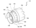
図1は、ミキサ−イジェクタ風力タービン(MEWT)としても知られる形態の本発明の風力タービンの第1の実施形態の斜視図である。MEWTは、他の現行の種類の風力タービンと同じ面積を有するタービンにおいてより多くの出力を抽出することができるよう、風力タービンの効率を改善するためにシュラウド付きのインペラ、プロペラ、またはロータ/ステータを使用した、新しい種類の風力タービンである。これにより、MEWTは、最も一般的な種類の風力タービン、すなわち水平軸風力タービン(HAWT)よりも大きな面積から空気を引き込む。 FIG. 1 is a perspective view of a first embodiment of a wind turbine of the present invention in a form also known as a mixer-ejector wind turbine (MEWT). The MEWT has a shrouded impeller, propeller, or rotor / stator to improve the efficiency of the wind turbine so that it can extract more power in a turbine that has the same area as other current types of wind turbines A new type of wind turbine using Thereby, the MEWT draws air from a larger area than the most common type of wind turbine, the horizontal axis wind turbine (HAWT).
風力タービンは、理論的には、風力タービンを通過する風の潜在的なエネルギーの最大で59.3%(ベッツの限界として知られる最大値)を捕捉することができる。風力タービンによって捕捉されるエネルギーの量を、タービンの効率と称することもできる。MEWTは、ベッツの限界を超えることができる。 The wind turbine can theoretically capture up to 59.3% of the potential energy of the wind passing through the wind turbine (the maximum known as the Betz limit). The amount of energy captured by the wind turbine can also be referred to as turbine efficiency. MEWT can exceed the Betz limit.
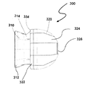
図1を参照すると、タービン10が、タービンシュラウド30の入り口端32に配置されたインペラ20を備えている。インペラは、通常は、羽根が軸へと取り付けられて回転可能であり、羽根を回転させる風から出力またはエネルギーを生成することができる、任意のアセンブリとすることができる。ここに示されているように、インペラ20は、ロータ−ステータアセンブリである。ステータ22が、タービンシュラウド30に係合し、ロータ(図示されていない)が、モータ/発電機(図示されていない)に係合する。ステータ22は、ロータへと達する前に空気の向きを変える非回転の羽根24を有している。その結果、ロータの羽根が回転し、発電機において電力が生成される。シュラウド30は、環状の翼34を備えており、すなわち換言すると、ほぼ円筒形であって、翼の形状を有しており、翼が、タービンシュラウドの内側(すなわち、シュラウドの内部)に比較的低い圧力を生成し、タービンシュラウドの外側(すなわち、シュラウドの外部)に比較的高い圧力を生成するように構成されている。換言すると、環状の翼が、米国特許出願公開第2009/0087308号(その開示の全体が、参照により本明細書にそのまま組み込まれる)の図4、7、12、14、17、および19に見て取ることができるように、航空機の翼のように形作られた断面を有している。インペラおよびモータ/発電機は、タービンシュラウド内に収容されている。タービンシュラウド30は、シュラウドの出口端または排気端の周囲にミキサローブ40をさらに有することができる。ミキサローブは、排気端の外周を巡っておおむね一様に分布している。ミキサローブは、一般に、空気が出て行くタービンシュラウドの排気端36に、外周を巡っておおむね頂点および谷の形状を持たせる。換言すると、ローブ40は、シュラウドの後縁38に沿って配置されている。
With reference to FIG. 1, a
さらにタービン10は、イジェクタシュラウド50をタービンシュラウドに係合させて備えている。イジェクタシュラウドは、環状の翼54を備えており、換言すると、ほぼ円筒形であって、翼の形状を有しており、翼が、イジェクタの内側(すなわち、タービンシュラウド30とイジェクタシュラウド50との間)に比較的高い圧力を生成し、イジェクタシュラウド50の外側に比較的低い圧力を生成するように構成されている。イジェクタシュラウドも、ミキサローブ60を有することができ、その場合、風力タービンは、ミキサ−イジェクタ風力タービンとなる。ミキサローブは、一般に、空気が出て行くイジェクタの排気端56に、外周を巡っておおむね頂点および谷の形状を持たせている。換言すると、ミキサローブが、イジェクタシュラウド50の後縁58に沿って配置されている。
Further, the
イジェクタシュラウド50は、タービンシュラウド30よりも大きい直径を有している。タービンシュラウド30が、イジェクタシュラウド50に係合している。換言すると、タービンシュラウドの排気端36が、イジェクタシュラウドの入り口端52にはまり込んでおり、あるいはイジェクタシュラウドの入り口端52が、タービンシュラウドの排気端36を囲んでいる。タービンシュラウド30およびイジェクタシュラウド50は、両者の間に空気を流すことができるように寸法付けられている。換言すると、イジェクタシュラウド50が、タービンシュラウド30の周囲に同心に配置され、タービンシュラウド30の下流に配置されている。インペラ20、タービンシュラウド30、およびイジェクタシュラウド50はすべて、共通の軸を共有しており、すなわち互いに同軸である。
The
ミキサローブ40、60が、先進する流れの混合および制御を可能にする。タービンシュラウドおよびイジェクタシュラウドは、航空機産業において使用される類似の形状から相違している。これは、MEWTにおいては流路が高エネルギーの空気をイジェクタシュラウドへもたらすためである。タービンシュラウドが、低エネルギーの空気をイジェクタシュラウドへともたらし、高エネルギーの空気が、低エネルギーの空気の周囲を囲み、低エネルギーの空気を吸い出し、低エネルギーの空気と混ざり合う。
風がロータを駆動するときに電気を生成させるために、モータ/発電機を使用することができる。風がロータを駆動するのに不充分な場合には、タービンの発電機を、インペラ20を駆動して空気をタービン10へと引き込んで通過させるためのモータとして使用することも可能である。
A motor / generator can be used to generate electricity when wind drives the rotor. If the wind is insufficient to drive the rotor, the turbine generator can also be used as a motor to drive the
再び図1を参照すると、タービンシュラウド30は、膨張可能部材70と、第1の剛構造部材72と、第2の剛構造部材74とを備えている。第1の剛体部材は、シュラウド30の前縁76を定めており、第2の剛体部材74は、複数のローブ40が外周を巡って設けられている後縁38を定めている。剛体部材72、74は、互いに向かい合わせに膨張可能部材70へと接続されており、すなわち膨張可能部材の両側に接続されている。第1の剛構造部材72は、環状である。第1の剛構造部材72は、インペラ20を支持するための構造を与えるとともに、空気をインペラを通って導くためのファンネルとしても機能する。膨張可能部材70は、後述されるように、薄いフィルム材料で製作される。剛体部材72、74は、可撓であってもよく、膨張可能部材70と比較して剛であればよいと考えられる。
Referring again to FIG. 1, the
イジェクタシュラウド50も、膨張可能部材80、第1の剛構造部材82、および第2の剛構造部材84を備えている。第1の剛体部材が、イジェクタ50の前縁86を定めており、第2の剛体部材84が、複数のローブ60が外周を巡って設けられている後縁58を定めている。剛体部材82、84は、互いに向かい合わせに膨張可能部材80へと接続されており、すなわち膨張可能部材の両側に接続されている。やはり、剛体部材82、84は、可撓であってもよく、膨張可能部材80との比較において剛であると考えられる。膨張可能部材70、80は、膨張させられる1つの大きなポケットを含むことができ、あるいは個別に膨張/収縮させることができる複数のポケットを含むことができる。
The
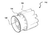
図2は、タービンの別の典型的な実施形態を示している。タービン110が、インペラ120、タービンシュラウド130、およびイジェクタシュラウド150を有している。この実施形態において、タービンシュラウド130は、膨張可能部材134へと接続された第1の剛構造部材132を備えている。第1の剛構造部材132が、シュラウド130の前縁136を定めている。シュラウドの膨張可能部材134は、タービンシュラウドの後縁138を巡って複数のローブ140をもたらすように形成されている。図1の実施形態と対照的に、剛体部材が1つだけ存在しており、この剛体部材に膨張可能部材が接続されている。同様に、イジェクタ150は、膨張可能部材154へと接続された第1の剛構造部材152を備えている。第1の剛体部材152が、イジェクタシュラウド150の後縁156を定めている。イジェクタの膨張可能部材154は、イジェクタシュラウドの後縁158を巡って複数のローブ160をもたらすように形成されている。換言すると、この実施形態においては、膨張式のタービンシュラウド130および/または膨張式のイジェクタシュラウド150に、ローブを定める剛性部材が存在していない。
FIG. 2 shows another exemplary embodiment of a turbine. The
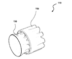
図3は、タービンの別の典型的な実施形態を示している。タービン110が、インペラ120、タービンシュラウド130、およびイジェクタシュラウド150を有している。この実施形態においては、タービンシュラウド130が、膨張可能部材からなり、イジェクタシュラウド150が、膨張可能部材からなっている。換言すると、タービンシュラウドまたはイジェクタシュラウドの前縁または後縁に剛構造部材が存在しない。
FIG. 3 shows another exemplary embodiment of a turbine. The
図4は、別の典型的な実施形態を示している。ここでは、タービンシュラウド130およびイジェクタシュラウド150が、膨張可能な材料で形成され、既存のタービンまたは推進装置へと後付けされるように構成された部分アセンブリを形成している。
FIG. 4 shows another exemplary embodiment. Here,
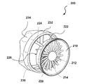
図5は、本発明の別の典型的な実施形態を示している。ここでは、タービン200が、インペラ210、タービンシュラウド220、およびイジェクタシュラウド230を備えている。インペラ210は、ロータ−ステータアセンブリである。ステータ212が、複数の羽根214を有している。タービンシュラウド220は、ステータ212を囲み、実質的に円形の形状を有しており、タービンシュラウドの前縁を定めている剛構造部材222を備えている。同様に、イジェクタシュラウド230も、やはり実質的に円形の形状を有しており、イジェクタシュラウドの前縁を定めている剛構造部材232を備えている。支柱224が、シュラウドの剛体部材222およびイジェクタの剛体部材232をつなぎ合わせている。タービンシュラウド220は、膨張可能部材(図示されていない)をさらに備えており、イジェクタシュラウド230も、膨張可能部材234を備えている。この実施形態において、膨張可能部材は、強風の状況または着氷性の嵐における保護のために、タービンの形状を変え、収縮して小さくなるように設計されている。シュラウドの剛構造部材222が、膨張可能部材を引き込むことができる中空な内部を備えている。この図において、中空な内部は、シュラウドの剛体部材222の後縁226に位置しており、見て取ることができないことを、理解すべきである。ここでは、タービンシュラウド220は、膨張可能部材を完全に圧縮してシュラウドの剛体部材222に収納した状態で示されている。同様に、イジェクタの膨張可能部材234も、収縮させ、イジェクタの剛構造部材232の中空な内部に収納可能になっている。
FIG. 5 illustrates another exemplary embodiment of the present invention. Here, the
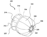
図6Aおよび6Bは、本発明の別の典型的な実施形態の2つの図を示している。タービン300が、同様にタービンシュラウド310およびイジェクタシュラウド320を備えている。タービンシュラウドは、剛構造部材312および膨張可能部材314(ここでは、完全に膨張した状態で図示されている)を備えている。イジェクタシュラウドも、剛構造部材322および膨張可能部材324を備えている。しかしながら、ここでは、イジェクタの膨張可能部材324が、膨張の程度に応じてさまざまな形態または形状をとることが可能な充分な柔軟性を有している。ここでは、膨張可能部材324が、排気端326の面積が小さくされるように、完全には膨張していない状態で図示されている。ここに示されているように、この面積の縮小により、タービンを通過する空気の流れが抑えられ、空気の流れが少なくなって、強風の状況において生じうるインペラまたはロータ−ステータアセンブリへの応力が小さくなる。換言すると、イジェクタの膨張可能部材324が、完全には膨張していない状態において、イジェクタの膨張可能部材の後縁332によって囲まれる面積330がイジェクタシュラウドの後縁334によって囲まれる面積よりも小さくなるように構成されている。前縁によって囲まれる面積は、タービンシュラウド310とイジェクタシュラウド320との間の環状の面積だけでなく、前縁によって定められる全面積を指していることに、注意すべきである。
6A and 6B show two views of another exemplary embodiment of the present invention.
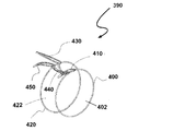
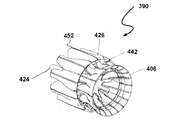
図7A〜7Cが、本発明の風力タービンに有用なシュラウドおよび/またはイジェクタの他の典型的な実施形態の構成の種々の段階を示している。これらの図に、インペラは示されていない。ここで、シュラウド/イジェクタの組み合わせ390が、タービンシュラウドの入り口端402および排気端404を協働して定める円形部材400および複数のシュラウド第1リブ部材410を備えている。次いで、円形部材400および複数のシュラウド第1リブ部材410が、外側フィルム材料406によって覆われ、タービンシュラウドが完成される。タービンシュラウドの排気端404は、入り口端402よりも小さい面積を有することができる。イジェクタシュラウドも同様に、イジェクタシュラウドの入り口端422および排気端424を協働して定める円形部材420および複数のイジェクタ第1リブ部材430を備えている。次いで、円形部材420および複数のイジェクタ第1リブ部材430が、外側フィルム材料426によって覆われ、イジェクタシュラウドが完成される。いくつかの実施形態においては、シュラウドの円形部材400およびイジェクタの円形部材420も、シュラウド第1リブ部材410によって互いに接続される。
7A-7C illustrate various stages of construction of another exemplary embodiment of a shroud and / or ejector useful in the wind turbine of the present invention. In these figures, the impeller is not shown. Here, the shroud /
さらなる実施形態においては、タービンシュラウドが、複数のシュラウド第2リブ部材440を含むことができる。シュラウド第2リブ部材440は、シュラウドの円形部材400とイジェクタの円形部材420とをつなぎ合わせる。シュラウド第1リブ部材410およびシュラウド第2リブ部材440が協働し、シュラウドの排気端404に複数のミキサローブ442を定める。一般に、シュラウド第1リブ部材410およびシュラウド第2リブ部材440は、異なる形状を有している。さらなる実施形態においては、イジェクタシュラウドも同様に、複数のイジェクタ第2リブ部材450を備えることができる。イジェクタ第1リブ部材430およびイジェクタ第2リブ部材450が協働し、イジェクタの排気端424に複数のミキサローブ452を定める。一般に、イジェクタ第1リブ部材430およびイジェクタ第2リブ部材450は、異なる形状を有している。
In further embodiments, the turbine shroud may include a plurality of shroud
図7Aに見られるように、シュラウド第1リブ部材410およびイジェクタ第1リブ部材430は、同じ位置でイジェクタの円形部材420へとつながっている。同様に、シュラウド第2リブ部材440およびイジェクタ第2リブ部材450が、同じ位置でイジェクタの円形部材420へとつながっている。種々のリブ部材について、この同じ位置における接続は必須ではない。
As seen in FIG. 7A, the shroud
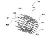
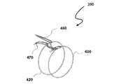
あるいは、図7Dに示される通り、シュラウド/イジェクタの組み合わせ390を、第1の円形部材400、第2の円形部材420、複数の第1の内部リブ460、および複数の第2の内部リブ470からなると考えることができる。2つの円形部材、第1の内部リブ、および第2の内部リブの組み合わせが、タービンシュラウド、タービンシュラウドのローブ、イジェクタシュラウド、およびイジェクタシュラウドのローブの形状を定める。タービンシュラウドが、2つの円形部材400および420の間の領域によって定められる一方で、イジェクタシュラウドは、第2の円形部材420の下流に配置されている。図7Aと比較して、第1の内部リブ460を、シュラウド第1リブ部材410とイジェクタ第1リブ部材430とを一部品に組み合わせたものと考えることができる一方で、第2の内部リブ470を、シュラウド第2リブ部材440とイジェクタ第2リブ部材450とを一部品に組み合わせたものと考えることができる。
Alternatively, as shown in FIG. 7D, the shroud /
図8A〜8Cは、図7A〜7Cに示したような種々の実施形態において使用するために適した内部リブの種々の実施形態の側面図である。図8Aにおいては、おおむね剛性のリブ500を協働して形成するように、一体的に形成された弓形部材510および横部材520を備えている。部材は、一般的に軽量であり、支柱504によってつなぎ合わせられた梁502と考えることができる。弓形部材510が、タービンシュラウドの形状を定める一方で、横部材520が、イジェクタシュラウドの形状を定める。
8A-8C are side views of various embodiments of internal ribs suitable for use in various embodiments as shown in FIGS. 7A-7C. In FIG. 8A, an
図8Bを参照すると、リブ500が、静止部材530および作動部材540を備えている。静止部材530が、タービンシュラウドの形状を定める一方で、作動部材540が、イジェクタシュラウドの形状を定める。静止部材530および作動部材540は、両者の間の角度を定める枢支部550によって、下縁508に沿って接続されている。静止部材530および作動部材540は、スリーブまたは直線運動部材560によって上縁506に沿って接続されている。アクチュエータ570が、静止部材530および作動部材540の間の角度を変化させるように、静止部材530および作動部材540の両者に係合し、それによりシュラウドおよび/またはイジェクタの形状を変化させる。実線の輪郭が、短縮位置または直線位置を示している一方で、破線の輪郭は、延長位置または斜め位置を示している。この形状変化の能力が、タービンシュラウドまたはイジェクタシュラウドの全体の骨格の移動/形状変化を可能にする。
Referring to FIG. 8B, the
図8Cを参照すると、静止部材530および作動部材540が、上縁506および下縁508の両方において、アクチュエータ570との協働によってリブ500の長さを変化させるスリーブまたは直線運動部材560によってつなぎ合わせられている。
Referring to FIG. 8C, the
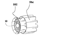
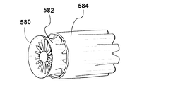
図8Dは、タービンシュラウド582およびイジェクタシュラウド584を備えるタービン580を示している。ここで、イジェクタのリブ部材(図示されていない)は、それぞれ短縮位置にある。図8Eにおいては、イジェクタシュラウドのリブ部材が、それぞれ延長位置にあり、より長さの長いイジェクタおよび異なる空気の流れの特性をもたらしている。このようにして、風力タービンのリブ部材の柔軟な性状が、さまざまな風の状況に対応するための構成の変化を可能にする。
FIG. 8D shows a
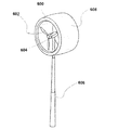
図9においては、風力タービン600が、発電機604に取り付けられたプロペラ602として示されており、柱606に支持されているインペラを有している。膨張可能なシュラウド608が、プロペラ602の周囲に配置されている。このようにして、膨張可能なシュラウドを、既存の種類の風力タービンにおいて使用することができる。
In FIG. 9, a
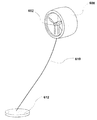
図10は、タービン600が柱によって支持されるのではない別の実施形態である。代わりに、膨張可能なシュラウド608が、水素、ヘリウム、アンモニア、またはメタン、などといった空気よりも軽い気体で膨張させられている。これにより、タービン600を自由に上昇させるための充分な浮力がもたらされる。タービン600は、繋留索またはケーブル610によってつながれており、索610が、索610の長さを延長または短縮することができるコントローラへと接続されている。したがって、索610以外の支持構造が不要である。ベース612が、索610の長さを制御するためのリールまたはスプールを含むことができる。この特徴は、過度に強い風の場合にタービン600を下降させる簡潔かつ素早い応答の手段を提供する。
FIG. 10 is another embodiment in which the
本明細書に記載の膨張可能部材は、揚力の大きさまたは膨張の程度を制御するために、いくつかの内部チャンバを備えることができる。これらの内部チャンバを、適宜、膨張可能部材の円周を巡って配置することができ、あるいは膨張可能部材の一端から他端へと配置することができる。 The inflatable members described herein can include several internal chambers to control the amount of lift or the degree of expansion. These internal chambers can be placed around the circumference of the inflatable member as appropriate, or can be placed from one end of the inflatable member to the other.
シュラウド用および/またはイジェクタ用の膨張可能部材ならびに外側フィルムを形成するために使用される薄いフィルム材料を、一般的には、任意のポリマー材料または布地材料で形成することができる。典型的な材料として、ポリウレタン、ポリフルオロポリマー、および同様の組成の多層フィルムが挙げられる。スパンデックスタイプの布地など、伸縮自在の布地も、使用することが可能である。 The thin film material used to form the expandable member for shroud and / or ejector and the outer film can generally be formed of any polymeric or fabric material. Typical materials include polyurethane, polyfluoropolymer, and multilayer films of similar composition. Stretchable fabrics such as spandex type fabrics can also be used.
ポリウレタンフィルムは、丈夫で、良好な耐候性を有している。ポリエステルタイプのポリウレタンフィルムは、ポリエーテルタイプのポリウレタンフィルムよりも親水的な分解の影響を受けやすい傾向にある。また、これらのポリウレタンフィルムの脂肪族バージョンは、一般的に、紫外線によく耐える。 The polyurethane film is strong and has good weather resistance. Polyester type polyurethane films tend to be more susceptible to hydrophilic degradation than polyether type polyurethane films. Also, the aliphatic versions of these polyurethane films generally resist UV well.
典型的なポリフルオロポリマーとして、ポリフッ化ビニリデン(PVDF)およびポリフッ化ビニル(PVF)が挙げられる。市販のバージョンが、KYNARおよびTEDLARとして入手可能である。ポリフルオロポリマーは、一般的に、きわめて表面エネルギーが低いため、表面への塵埃の付着をある程度は防止でき、より高い表面エネルギーを有する材料と比べて氷をより容易に落とすことができる。 Typical polyfluoropolymers include polyvinylidene fluoride (PVDF) and polyvinyl fluoride (PVF). Commercial versions are available as KYNAR and TEDLAR. Since polyfluoropolymers generally have very low surface energy, they can prevent dust from adhering to the surface to some extent, and can drop ice more easily than materials with higher surface energy.
フィルム/布地の複合材料も、膨張可能部材または外側フィルムの形成用として、発泡体などの裏打ちとともに想定することができる。 Film / fabric composites can also be envisioned with foam backings for the formation of inflatable members or outer films.
膨張可能部材を、ウレタンフィルムの嚢(Bladder)および嚢を覆って嚢に強度および耐久性を付与する織物カバーまたは編み物カバーで構成することもできる。織物材料または編み物材料は、ポリエステル、プレストレスポリエステル、芳香族ポリエステル(日本国のKuraray社が製造している商品名VECTRAN(登録商標))、p−フェニレンテレフタルアミド(PpPTA)(Akzo社の商品名TWARON)、PPTA(ポリ−パラフェニレンテレフタルアミド(DuPont社の商品名KEVLAR)、およびポリトリメチレンテレフタレート(Shell社の商品名CORTERRA)であってもよい。織物カバーまたは編み物カバーの外側を、シス−ポリイソプレン、ポリウレタン、エポキシ、またはポリ塩化ビニルなどの種々のポリマーでコートすることができる。これは、織物または編み物を、UVなどの環境の攻撃から保護し、あるいは繊維を傷めかねない砂または他の物質による摩耗から保護する。製造者として、マサチューセッツ州LowellのFederal Fabrics−Fibers、ニューハンプシャー州New IpswichのWarwick Mills、カリフォルニア州Lake ElsinoreのVertigo lnc、およびデラウェア州FredericaのILC Doverが挙げられる。また、膨張可能部材の一部分または全体を、真空樹脂含浸法(VARTM)による反応性ポリマーの導入または予め含浸させたポリマー(放射線、遊離基開始、またはイソシアネートによる架橋によって硬化する不飽和ポリエステル、エポキシ、アクリレート、またはウレタンなど)の硬化を使用して補強することができる。 The inflatable member can also be comprised of a urethane film bladder and a woven or knitted cover that covers the bladder and provides strength and durability to the bladder. Woven or knitted materials are polyester, pre-stressed polyester, aromatic polyester (trade name VECTRAN (registered trademark) manufactured by Kuraray of Japan), p-phenylene terephthalamide (PpPTA) (trade name of Akzo) TWARON), PPTA (poly-paraphenylene terephthalamide (DuPont's trade name KEVLAR), and polytrimethylene terephthalate (Shell's trade name CORTERRA). Can be coated with various polymers such as polyisoprene, polyurethane, epoxy, or polyvinyl chloride, which protects the fabric or knitting from environmental attack such as UV or sand or other that can damage the fiber Protects against abrasion from materials: Manufacturers include Federal Fabrics-Fibers, Lowell, Massachusetts, Warwick Mills, New Ipswich, New Hampshire, Vertico Inc, Lake Elsinore, California, and Fred, Delta, Delaware. Part or all of the possible member is introduced by reactive polymer introduction by vacuum resin impregnation (VARTM) or pre-impregnated polymer (unsaturated polyester, epoxy, acrylate, or cured by radiation, free radical initiation, or cross-linking with isocyanate, or Can be reinforced using curing of urethane, etc.).
本発明の風力タービンにおけるシュラウドおよび/またはイジェクタの膨張可能な構成は、タービンを従来のタービンよりも大幅に軽量にすることを可能にする。したがって、あまり頑丈でない支持塔を使用することができる。 The expandable configuration of the shroud and / or ejector in the wind turbine of the present invention allows the turbine to be significantly lighter than conventional turbines. Thus, less rigid support towers can be used.
本発明のシステムおよび方法を、典型的な実施形態を参照して説明した。当然ながら、以上の詳細な説明を検討および理解した者であれば、いくつかの変更および改変に想到できるであろう。上述の典型的な実施形態を、そのような変更および改変のすべてを、それらが添付の特許請求の範囲およびその均等物の範囲にある限りにおいて包含するものと解釈すべきである。 The system and method of the present invention have been described with reference to exemplary embodiments. Of course, several changes and modifications will become apparent to those skilled in the art upon review and understanding of the above detailed description. The exemplary embodiments described above should be construed to include all such changes and modifications as long as they fall within the scope of the appended claims and their equivalents.
Claims (22)
前記インペラの周囲に配置されたタービンシュラウドと
を備えており、
前記タービンシュラウドが、膨張可能部材を含んでいる風力タービン。 Impeller,
A turbine shroud disposed around the impeller,
A wind turbine in which the turbine shroud includes an expandable member.
前記タービンシュラウドの周囲に同軸に配置されたイジェクタシュラウドと
を備えており、
前記タービンシュラウドが、シュラウド円形部材と、該シュラウド円形部材に係合する複数のシュラウド第1リブ部材と、シュラウド外側フィルムとを備えており、前記シュラウド円形部材および前記複数のシュラウド第1リブ部材が、前記シュラウドの入り口端および排気端を定めており、
前記イジェクタシュラウドが、イジェクタ円形部材と、該イジェクタ円形部材に係合する複数のイジェクタ第1リブ部材と、イジェクタ外側フィルムとを備えており、前記イジェクタ円形部材および前記複数のイジェクタ第1リブ部材が、前記イジェクタシュラウドの入り口端および排気端を定めている風力タービン。 A turbine shroud,
An ejector shroud disposed coaxially around the turbine shroud,
The turbine shroud includes a shroud circular member, a plurality of shroud first rib members engaged with the shroud circular member, and a shroud outer film, and the shroud circular member and the plurality of shroud first rib members are included. , Defining an inlet end and an exhaust end of the shroud,
The ejector shroud includes an ejector circular member, a plurality of ejector first rib members that engage with the ejector circular member, and an ejector outer film, and the ejector circular member and the plurality of ejector first rib members include A wind turbine defining an inlet end and an exhaust end of the ejector shroud.
前記複数のシュラウド第1リブ部材および前記複数のシュラウド第2リブ部材が協働して、前記タービンシュラウドの排気端に複数のミキサローブを定めている請求項17に記載の風力タービン。 The turbine shroud further comprises a plurality of shroud second rib members, each shroud second rib member extending between the shroud circular member and the ejector circular member;
The wind turbine of claim 17, wherein the plurality of shroud first rib members and the plurality of shroud second rib members cooperate to define a plurality of mixer lobes at an exhaust end of the turbine shroud.
前記複数のイジェクタ第1リブ部材および前記複数のイジェクタ第2リブ部材が協働して、前記イジェクタシュラウドの排気端に複数のミキサローブを定めている請求項17に記載の風力タービン。 The ejector shroud further includes a plurality of ejector second rib members that engage with the ejector circular member;
The wind turbine according to claim 17, wherein the plurality of ejector first rib members and the plurality of ejector second rib members cooperate to define a plurality of mixer lobes at an exhaust end of the ejector shroud.
前記インペラの周囲に配置され、排気端の周囲に配置された複数の混合ローブを有しているタービンシュラウドと、
前記タービンシュラウドの周囲に配置され、膨張可能部材を含んでいるイジェクタシュラウドと
を備える風力タービン。 Impeller,
A turbine shroud disposed around the impeller and having a plurality of mixing lobes disposed around the exhaust end;
A wind turbine comprising an ejector shroud disposed around the turbine shroud and including an inflatable member.
Applications Claiming Priority (3)
| Application Number | Priority Date | Filing Date | Title |
|---|---|---|---|
| US19135808P | 2008-09-08 | 2008-09-08 | |
| US61/191,358 | 2008-09-08 | ||
| PCT/US2009/056185 WO2010028342A2 (en) | 2008-09-08 | 2009-09-08 | Inflatable wind turbine |
Publications (2)
| Publication Number | Publication Date |
|---|---|
| JP2012502224A true JP2012502224A (en) | 2012-01-26 |
| JP2012502224A5 JP2012502224A5 (en) | 2012-12-20 |
Family
ID=41797913
Family Applications (1)
| Application Number | Title | Priority Date | Filing Date |
|---|---|---|---|
| JP2011526263A Pending JP2012502224A (en) | 2008-09-08 | 2009-09-08 | Inflatable wind turbine |
Country Status (7)
| Country | Link |
|---|---|
| EP (1) | EP2329142A4 (en) |
| JP (1) | JP2012502224A (en) |
| KR (1) | KR20110050701A (en) |
| CN (1) | CN102209847A (en) |
| AU (1) | AU2009289421A1 (en) |
| CA (1) | CA2736461A1 (en) |
| WO (1) | WO2010028342A2 (en) |
Families Citing this family (15)
| Publication number | Priority date | Publication date | Assignee | Title |
|---|---|---|---|---|
| US8801362B2 (en) | 2007-03-23 | 2014-08-12 | Ogin, Inc. | Fluid turbine |
| US8393850B2 (en) | 2008-09-08 | 2013-03-12 | Flodesign Wind Turbine Corp. | Inflatable wind turbine |
| US8714923B2 (en) | 2007-03-23 | 2014-05-06 | Ogin, Inc. | Fluid turbine |
| EP2438297A2 (en) | 2009-06-03 | 2012-04-11 | FloDesign Wind Turbine Corp. | Inflatable wind turbine |
| WO2010141867A2 (en) * | 2009-06-04 | 2010-12-09 | Flodesign Wind Turbine Corporation | Coated shrouded wind turbine |
| AU2011329643A1 (en) * | 2010-11-19 | 2013-05-23 | Flodesign Wind Turbine Corp. | Fluid turbine |
| GB2490170B (en) * | 2011-04-21 | 2014-06-11 | Anakata Wind Power Resources S A R L | A horizontal axis wind turbine with diffuser |
| US8672624B2 (en) * | 2011-04-27 | 2014-03-18 | SkyWolf Wind Turbine Corp. | High efficiency wind turbine having increased laminar airflow |
| US8851836B2 (en) | 2011-04-27 | 2014-10-07 | SkyWolf Wind Turbine Corp. | High efficiency wind turbine including photovoltaic cells |
| US9322391B2 (en) | 2011-04-27 | 2016-04-26 | SkyWolf Wind Turbine Corp. | Housing for a high efficiency wind turbine |
| US8721279B2 (en) | 2011-04-27 | 2014-05-13 | SkyWolf Wind Turbines Corp. | Multiple mixing internal external fluid driven high efficiency wind turbine having reduced downstream pressure |
| JP2013096403A (en) * | 2011-11-01 | 2013-05-20 | Yaheitai Hayashi | Outdoor facility device enabling columnar multi-connection installation by providing buoyancy (specific weight) regulation function and fluid direction guide function for turbine (water turbine, wind turbine) installed in fluid for power generation (power) |
| EP3156642A1 (en) * | 2015-10-14 | 2017-04-19 | FlowGen Development & Management GmbH | Flow energy installation, in particular a wind energy installation |
| GB201700675D0 (en) * | 2017-01-14 | 2017-03-01 | Lewis Stephen Desmond | Reduced cost wind power generator |
| DK3473848T3 (en) | 2017-10-20 | 2022-12-12 | Flowgen Development & Man Ag | FLOW ENERGY PLANT, ESPECIALLY CAPE WIND TURBINE |
Citations (5)
| Publication number | Priority date | Publication date | Assignee | Title |
|---|---|---|---|---|
| JPS50128032A (en) * | 1974-03-29 | 1975-10-08 | ||
| JPS5449433U (en) * | 1977-09-14 | 1979-04-05 | ||
| JPS54180852U (en) * | 1978-06-12 | 1979-12-21 | ||
| JPS5751967A (en) * | 1980-07-26 | 1982-03-27 | Gilchrist Timothy M | Wind force turbine construction |
| US5669758A (en) * | 1996-01-24 | 1997-09-23 | Williamson; Larry D. | Wind turbine |
Family Cites Families (6)
| Publication number | Priority date | Publication date | Assignee | Title |
|---|---|---|---|---|
| US4166596A (en) * | 1978-01-31 | 1979-09-04 | Mouton William J Jr | Airship power turbine |
| CN2073944U (en) * | 1990-07-04 | 1991-03-27 | 南京航空学院 | Wind-driven generator |
| US5761900A (en) * | 1995-10-11 | 1998-06-09 | Stage Iii Technologies, L.C. | Two-stage mixer ejector suppressor |
| RU2124142C1 (en) * | 1998-03-25 | 1998-12-27 | Орлов Игорь Сергеевич | Wind-driven electric plant |
| US7220096B2 (en) * | 2004-03-16 | 2007-05-22 | Tocher Angus J | Habitat friendly, multiple impellor, wind energy extraction |
| US20080048453A1 (en) * | 2006-07-31 | 2008-02-28 | Amick Douglas J | Tethered Wind Turbine |
-
2009
- 2009-09-08 EP EP09812361.5A patent/EP2329142A4/en not_active Withdrawn
- 2009-09-08 KR KR1020117007265A patent/KR20110050701A/en not_active Application Discontinuation
- 2009-09-08 JP JP2011526263A patent/JP2012502224A/en active Pending
- 2009-09-08 CN CN2009801444492A patent/CN102209847A/en active Pending
- 2009-09-08 WO PCT/US2009/056185 patent/WO2010028342A2/en active Application Filing
- 2009-09-08 AU AU2009289421A patent/AU2009289421A1/en not_active Abandoned
- 2009-09-08 CA CA2736461A patent/CA2736461A1/en not_active Abandoned
Patent Citations (5)
| Publication number | Priority date | Publication date | Assignee | Title |
|---|---|---|---|---|
| JPS50128032A (en) * | 1974-03-29 | 1975-10-08 | ||
| JPS5449433U (en) * | 1977-09-14 | 1979-04-05 | ||
| JPS54180852U (en) * | 1978-06-12 | 1979-12-21 | ||
| JPS5751967A (en) * | 1980-07-26 | 1982-03-27 | Gilchrist Timothy M | Wind force turbine construction |
| US5669758A (en) * | 1996-01-24 | 1997-09-23 | Williamson; Larry D. | Wind turbine |
Also Published As
| Publication number | Publication date |
|---|---|
| CA2736461A1 (en) | 2010-03-11 |
| WO2010028342A2 (en) | 2010-03-11 |
| CN102209847A (en) | 2011-10-05 |
| KR20110050701A (en) | 2011-05-16 |
| AU2009289421A1 (en) | 2010-03-11 |
| EP2329142A2 (en) | 2011-06-08 |
| WO2010028342A3 (en) | 2010-07-15 |
| EP2329142A4 (en) | 2014-01-01 |
Similar Documents
| Publication | Publication Date | Title |
|---|---|---|
| JP2012502224A (en) | Inflatable wind turbine | |
| US8393850B2 (en) | Inflatable wind turbine | |
| AU2010232745B2 (en) | Segmented wind turbine | |
| US20100284802A1 (en) | Inflatable wind turbine | |
| US8545187B2 (en) | Systems and methods for protecting a wind turbine in high wind conditions | |
| US20100172759A1 (en) | Retractable wind turbines | |
| EP2483554B1 (en) | Tapered hollow helical turbine for energy transduction | |
| US7847426B1 (en) | Wind power generation | |
| WO2007084447A2 (en) | Wind turbine | |
| KR20130026490A (en) | Vertical-axis wind turbine | |
| US20110027067A1 (en) | Coated shrouded wind turbine | |
| JP2014513233A (en) | Wind turbine enhanced by diffuser | |
| US20110014038A1 (en) | Wind turbine with skeleton-and-skin structure | |
| US8109732B2 (en) | Horizontal-axis wind generator | |
| US20100310370A1 (en) | Turbine with vanes and tethers that adjust to the wind | |
| AU2010256544A1 (en) | Inflatable wind turbine | |
| US8647050B2 (en) | Variable partial wind wall | |
| WO2010141867A2 (en) | Coated shrouded wind turbine | |
| EP3085953B1 (en) | Wind turbine dome and method of assembly | |
| WO2011097023A1 (en) | Turbine blade | |
| CN101725479A (en) | Self-elevating pylon diffuser wind power generating equipment |
Legal Events
| Date | Code | Title | Description |
|---|---|---|---|
| A521 | Written amendment |
Free format text: JAPANESE INTERMEDIATE CODE: A523 Effective date: 20120905 |
|
| A621 | Written request for application examination |
Free format text: JAPANESE INTERMEDIATE CODE: A621 Effective date: 20120905 |
|
| RD02 | Notification of acceptance of power of attorney |
Free format text: JAPANESE INTERMEDIATE CODE: A7422 Effective date: 20120905 |
|
| A521 | Written amendment |
Free format text: JAPANESE INTERMEDIATE CODE: A523 Effective date: 20121023 |
|
| A977 | Report on retrieval |
Free format text: JAPANESE INTERMEDIATE CODE: A971007 Effective date: 20131031 |
|
| A02 | Decision of refusal |
Free format text: JAPANESE INTERMEDIATE CODE: A02 Effective date: 20140430 |