CN102209847A - Inflatable wind turbine - Google Patents
Inflatable wind turbine Download PDFInfo
- Publication number
- CN102209847A CN102209847A CN2009801444492A CN200980144449A CN102209847A CN 102209847 A CN102209847 A CN 102209847A CN 2009801444492 A CN2009801444492 A CN 2009801444492A CN 200980144449 A CN200980144449 A CN 200980144449A CN 102209847 A CN102209847 A CN 102209847A
- Authority
- CN
- China
- Prior art keywords
- sparger
- outer cover
- wind turbine
- ejector shroud
- rigid structure
- Prior art date
- Legal status (The legal status is an assumption and is not a legal conclusion. Google has not performed a legal analysis and makes no representation as to the accuracy of the status listed.)
- Pending
Links
- 230000008859 change Effects 0.000 claims description 9
- 210000002808 connective tissue Anatomy 0.000 claims description 6
- 239000000463 material Substances 0.000 description 10
- 238000000034 method Methods 0.000 description 8
- 229920000642 polymer Polymers 0.000 description 6
- 230000008569 process Effects 0.000 description 5
- 239000004744 fabric Substances 0.000 description 4
- 229920002313 fluoropolymer Polymers 0.000 description 4
- 239000004811 fluoropolymer Substances 0.000 description 4
- 230000004048 modification Effects 0.000 description 4
- 238000012986 modification Methods 0.000 description 4
- 238000009954 braiding Methods 0.000 description 3
- 239000000835 fiber Substances 0.000 description 3
- 239000010408 film Substances 0.000 description 3
- 239000012528 membrane Substances 0.000 description 3
- -1 phenylene terephthalate amine Chemical class 0.000 description 3
- 229920002620 polyvinyl fluoride Polymers 0.000 description 3
- 235000015170 shellfish Nutrition 0.000 description 3
- QGZKDVFQNNGYKY-UHFFFAOYSA-N Ammonia Chemical compound N QGZKDVFQNNGYKY-UHFFFAOYSA-N 0.000 description 2
- 239000002033 PVDF binder Substances 0.000 description 2
- 125000001931 aliphatic group Chemical group 0.000 description 2
- 230000000712 assembly Effects 0.000 description 2
- 238000000429 assembly Methods 0.000 description 2
- 230000010339 dilation Effects 0.000 description 2
- 230000005611 electricity Effects 0.000 description 2
- 239000003822 epoxy resin Substances 0.000 description 2
- 239000000284 extract Substances 0.000 description 2
- 239000012530 fluid Substances 0.000 description 2
- 230000007246 mechanism Effects 0.000 description 2
- VNWKTOKETHGBQD-UHFFFAOYSA-N methane Chemical compound C VNWKTOKETHGBQD-UHFFFAOYSA-N 0.000 description 2
- 229920003366 poly(p-phenylene terephthalamide) Polymers 0.000 description 2
- 229920000647 polyepoxide Polymers 0.000 description 2
- 229920000728 polyester Polymers 0.000 description 2
- 239000004814 polyurethane Substances 0.000 description 2
- 229920002635 polyurethane Polymers 0.000 description 2
- 229920006264 polyurethane film Polymers 0.000 description 2
- 229920002981 polyvinylidene fluoride Polymers 0.000 description 2
- 238000005381 potential energy Methods 0.000 description 2
- 239000010409 thin film Substances 0.000 description 2
- BQCIDUSAKPWEOX-UHFFFAOYSA-N 1,1-Difluoroethene Chemical group FC(F)=C BQCIDUSAKPWEOX-UHFFFAOYSA-N 0.000 description 1
- NIXOWILDQLNWCW-UHFFFAOYSA-M Acrylate Chemical compound [O-]C(=O)C=C NIXOWILDQLNWCW-UHFFFAOYSA-M 0.000 description 1
- JOYRKODLDBILNP-UHFFFAOYSA-N Ethyl urethane Chemical compound CCOC(N)=O JOYRKODLDBILNP-UHFFFAOYSA-N 0.000 description 1
- 229920000271 Kevlar® Polymers 0.000 description 1
- 229920006370 Kynar Polymers 0.000 description 1
- 229920002334 Spandex Polymers 0.000 description 1
- 229920000561 Twaron Polymers 0.000 description 1
- 229920000508 Vectran Polymers 0.000 description 1
- 239000004979 Vectran Substances 0.000 description 1
- 208000012886 Vertigo Diseases 0.000 description 1
- 230000009471 action Effects 0.000 description 1
- 229910021529 ammonia Inorganic materials 0.000 description 1
- 239000002775 capsule Substances 0.000 description 1
- 230000015556 catabolic process Effects 0.000 description 1
- 239000002131 composite material Substances 0.000 description 1
- 238000010276 construction Methods 0.000 description 1
- 238000006731 degradation reaction Methods 0.000 description 1
- 239000000428 dust Substances 0.000 description 1
- 230000003628 erosive effect Effects 0.000 description 1
- 239000006260 foam Substances 0.000 description 1
- 239000007789 gas Substances 0.000 description 1
- 239000001307 helium Substances 0.000 description 1
- 229910052734 helium Inorganic materials 0.000 description 1
- SWQJXJOGLNCZEY-UHFFFAOYSA-N helium atom Chemical compound [He] SWQJXJOGLNCZEY-UHFFFAOYSA-N 0.000 description 1
- 239000001257 hydrogen Substances 0.000 description 1
- 229910052739 hydrogen Inorganic materials 0.000 description 1
- 125000004435 hydrogen atom Chemical class [H]* 0.000 description 1
- 238000001802 infusion Methods 0.000 description 1
- 238000009434 installation Methods 0.000 description 1
- 239000012948 isocyanate Substances 0.000 description 1
- 150000002513 isocyanates Chemical class 0.000 description 1
- 239000004761 kevlar Substances 0.000 description 1
- 239000011159 matrix material Substances 0.000 description 1
- 238000000465 moulding Methods 0.000 description 1
- 229920001230 polyarylate Polymers 0.000 description 1
- 229920001195 polyisoprene Polymers 0.000 description 1
- 239000002861 polymer material Substances 0.000 description 1
- 229920000915 polyvinyl chloride Polymers 0.000 description 1
- 239000004800 polyvinyl chloride Substances 0.000 description 1
- 230000001681 protective effect Effects 0.000 description 1
- 230000005855 radiation Effects 0.000 description 1
- 229920013730 reactive polymer Polymers 0.000 description 1
- 230000009467 reduction Effects 0.000 description 1
- 229920005989 resin Polymers 0.000 description 1
- 239000011347 resin Substances 0.000 description 1
- 230000004044 response Effects 0.000 description 1
- 230000000630 rising effect Effects 0.000 description 1
- 239000004576 sand Substances 0.000 description 1
- 239000007787 solid Substances 0.000 description 1
- 239000004759 spandex Substances 0.000 description 1
- 238000012546 transfer Methods 0.000 description 1
- 239000004762 twaron Substances 0.000 description 1
- 229920006305 unsaturated polyester Polymers 0.000 description 1
- 150000003673 urethanes Chemical class 0.000 description 1
- 231100000889 vertigo Toxicity 0.000 description 1
Images


Classifications
-
- F—MECHANICAL ENGINEERING; LIGHTING; HEATING; WEAPONS; BLASTING
- F03—MACHINES OR ENGINES FOR LIQUIDS; WIND, SPRING, OR WEIGHT MOTORS; PRODUCING MECHANICAL POWER OR A REACTIVE PROPULSIVE THRUST, NOT OTHERWISE PROVIDED FOR
- F03D—WIND MOTORS
- F03D1/00—Wind motors with rotation axis substantially parallel to the air flow entering the rotor
- F03D1/04—Wind motors with rotation axis substantially parallel to the air flow entering the rotor having stationary wind-guiding means, e.g. with shrouds or channels
-
- F—MECHANICAL ENGINEERING; LIGHTING; HEATING; WEAPONS; BLASTING
- F03—MACHINES OR ENGINES FOR LIQUIDS; WIND, SPRING, OR WEIGHT MOTORS; PRODUCING MECHANICAL POWER OR A REACTIVE PROPULSIVE THRUST, NOT OTHERWISE PROVIDED FOR
- F03D—WIND MOTORS
- F03D13/00—Assembly, mounting or commissioning of wind motors; Arrangements specially adapted for transporting wind motor components
- F03D13/20—Arrangements for mounting or supporting wind motors; Masts or towers for wind motors
-
- F—MECHANICAL ENGINEERING; LIGHTING; HEATING; WEAPONS; BLASTING
- F03—MACHINES OR ENGINES FOR LIQUIDS; WIND, SPRING, OR WEIGHT MOTORS; PRODUCING MECHANICAL POWER OR A REACTIVE PROPULSIVE THRUST, NOT OTHERWISE PROVIDED FOR
- F03D—WIND MOTORS
- F03D9/00—Adaptations of wind motors for special use; Combinations of wind motors with apparatus driven thereby; Wind motors specially adapted for installation in particular locations
- F03D9/30—Wind motors specially adapted for installation in particular locations
- F03D9/32—Wind motors specially adapted for installation in particular locations on moving objects, e.g. vehicles
-
- F—MECHANICAL ENGINEERING; LIGHTING; HEATING; WEAPONS; BLASTING
- F03—MACHINES OR ENGINES FOR LIQUIDS; WIND, SPRING, OR WEIGHT MOTORS; PRODUCING MECHANICAL POWER OR A REACTIVE PROPULSIVE THRUST, NOT OTHERWISE PROVIDED FOR
- F03D—WIND MOTORS
- F03D9/00—Adaptations of wind motors for special use; Combinations of wind motors with apparatus driven thereby; Wind motors specially adapted for installation in particular locations
- F03D9/20—Wind motors characterised by the driven apparatus
- F03D9/25—Wind motors characterised by the driven apparatus the apparatus being an electrical generator
-
- F—MECHANICAL ENGINEERING; LIGHTING; HEATING; WEAPONS; BLASTING
- F05—INDEXING SCHEMES RELATING TO ENGINES OR PUMPS IN VARIOUS SUBCLASSES OF CLASSES F01-F04
- F05B—INDEXING SCHEME RELATING TO WIND, SPRING, WEIGHT, INERTIA OR LIKE MOTORS, TO MACHINES OR ENGINES FOR LIQUIDS COVERED BY SUBCLASSES F03B, F03D AND F03G
- F05B2240/00—Components
- F05B2240/10—Stators
- F05B2240/13—Stators to collect or cause flow towards or away from turbines
- F05B2240/133—Stators to collect or cause flow towards or away from turbines with a convergent-divergent guiding structure, e.g. a Venturi conduit
-
- F—MECHANICAL ENGINEERING; LIGHTING; HEATING; WEAPONS; BLASTING
- F05—INDEXING SCHEMES RELATING TO ENGINES OR PUMPS IN VARIOUS SUBCLASSES OF CLASSES F01-F04
- F05B—INDEXING SCHEME RELATING TO WIND, SPRING, WEIGHT, INERTIA OR LIKE MOTORS, TO MACHINES OR ENGINES FOR LIQUIDS COVERED BY SUBCLASSES F03B, F03D AND F03G
- F05B2240/00—Components
- F05B2240/90—Mounting on supporting structures or systems
- F05B2240/92—Mounting on supporting structures or systems on an airbourne structure
- F05B2240/922—Mounting on supporting structures or systems on an airbourne structure kept aloft due to buoyancy effects
-
- F—MECHANICAL ENGINEERING; LIGHTING; HEATING; WEAPONS; BLASTING
- F05—INDEXING SCHEMES RELATING TO ENGINES OR PUMPS IN VARIOUS SUBCLASSES OF CLASSES F01-F04
- F05B—INDEXING SCHEME RELATING TO WIND, SPRING, WEIGHT, INERTIA OR LIKE MOTORS, TO MACHINES OR ENGINES FOR LIQUIDS COVERED BY SUBCLASSES F03B, F03D AND F03G
- F05B2240/00—Components
- F05B2240/90—Mounting on supporting structures or systems
- F05B2240/98—Mounting on supporting structures or systems which is inflatable
-
- F—MECHANICAL ENGINEERING; LIGHTING; HEATING; WEAPONS; BLASTING
- F05—INDEXING SCHEMES RELATING TO ENGINES OR PUMPS IN VARIOUS SUBCLASSES OF CLASSES F01-F04
- F05B—INDEXING SCHEME RELATING TO WIND, SPRING, WEIGHT, INERTIA OR LIKE MOTORS, TO MACHINES OR ENGINES FOR LIQUIDS COVERED BY SUBCLASSES F03B, F03D AND F03G
- F05B2260/00—Function
- F05B2260/60—Fluid transfer
- F05B2260/601—Fluid transfer using an ejector or a jet pump
-
- Y—GENERAL TAGGING OF NEW TECHNOLOGICAL DEVELOPMENTS; GENERAL TAGGING OF CROSS-SECTIONAL TECHNOLOGIES SPANNING OVER SEVERAL SECTIONS OF THE IPC; TECHNICAL SUBJECTS COVERED BY FORMER USPC CROSS-REFERENCE ART COLLECTIONS [XRACs] AND DIGESTS
- Y02—TECHNOLOGIES OR APPLICATIONS FOR MITIGATION OR ADAPTATION AGAINST CLIMATE CHANGE
- Y02E—REDUCTION OF GREENHOUSE GAS [GHG] EMISSIONS, RELATED TO ENERGY GENERATION, TRANSMISSION OR DISTRIBUTION
- Y02E10/00—Energy generation through renewable energy sources
- Y02E10/70—Wind energy
- Y02E10/72—Wind turbines with rotation axis in wind direction
-
- Y—GENERAL TAGGING OF NEW TECHNOLOGICAL DEVELOPMENTS; GENERAL TAGGING OF CROSS-SECTIONAL TECHNOLOGIES SPANNING OVER SEVERAL SECTIONS OF THE IPC; TECHNICAL SUBJECTS COVERED BY FORMER USPC CROSS-REFERENCE ART COLLECTIONS [XRACs] AND DIGESTS
- Y02—TECHNOLOGIES OR APPLICATIONS FOR MITIGATION OR ADAPTATION AGAINST CLIMATE CHANGE
- Y02E—REDUCTION OF GREENHOUSE GAS [GHG] EMISSIONS, RELATED TO ENERGY GENERATION, TRANSMISSION OR DISTRIBUTION
- Y02E10/00—Energy generation through renewable energy sources
- Y02E10/70—Wind energy
- Y02E10/728—Onshore wind turbines
Landscapes
- Engineering & Computer Science (AREA)
- Life Sciences & Earth Sciences (AREA)
- Sustainable Development (AREA)
- Sustainable Energy (AREA)
- Chemical & Material Sciences (AREA)
- Combustion & Propulsion (AREA)
- Mechanical Engineering (AREA)
- General Engineering & Computer Science (AREA)
- Power Engineering (AREA)
- Wind Motors (AREA)
Abstract
A wind turbine has an impeller surrounded by a turbine shroud and/or an ejector shroud, wherein the turbine shroud and/or the ejector shroud include inflatable portions and/or flexible inflatable portions. In some embodiments, the turbine shroud and/or the ejector shroud include internal rib members whose shape or length can be changed to alter the characteristics of the wind turbine.
Description
The cross reference of related application
The application requires the preference of the interim patent No.61/191358 of the U.S. of submission on September 8th, 2008.The full content of this provisional application is incorporated this paper by reference into.
Technical field
The present invention relates to wind turbine, specifically, relate to the system that uses expansible elements.
Background technique
The wind turbine of the routine that is used to generate electricity has 2-5 the blade of opening of pulpous state setting in the shape of a spiral usually, and blade installation is on the horizontal axis that the gear-box with the driving generator is connected.This turbo machine is commonly called horizontal axis wind turbine or HAWT.Although HAWT is widely used, it is best that its efficient does not reach.Specifically, from through obtaining in the process of potential energy the wind of turbo machine, efficient can not surpass 59.3% the shellfish limit now.
Conventional wind turbine has three blades, and by be orientated or point to wind by computer-controlled motor.These turbo machines typically need 60 to 90 meters high support towers.These blades are usually with about 10 to 22 rev/mins rotating speed rotation.Although ring generator can be driven directly in some designs, utilize gear-box progressively to improve the speed that drives motor usually.Some turbo machines are with constant speed operation.Yet, can gather more energy by the solid state energy converter that adopts the variable speed turbine machine and turbo machine is engaged with generator.
All there are some problems in the structure of HAWT and operation.Be difficult to transport high tower and long blade.Need huge tower structure to support heavy blade, gear-box and generator.Need be very high and expensive hoist of equipment configuration and skilled operator.In when operation, the deflection control mechanism that HAWT need add is with blade steering wind.Typically there is the wide-angle impact to the wing in HAWT, and this wide-angle is impacted can not provide variable variation to the wing in distinguished and admirable.HAWT is difficult at place near the ground or operates in turbulent wind.The ice of being tied on engine compartment and blade may cause the minimizing and the safety problem of electric power.High HAWT may influence airport radar.This highly also makes HAWT lofty ground in big area as seen destroy the outward appearance of landscape and sometimes can cause locals's opposition.Finally, the modification of downwind (downwind variant) suffers because of the turbulent flow fatigue and the structural failure that cause.
Expectation reduces the weight and the size of wind turbine.
Summary of the invention
The invention describes the wind turbine that a kind of weight and size all reduce.Specifically, wind turbine comprises outer cover and/or the sparger with expansible elements.This wind turbine is lighter.Outer cover that expands and/or sparger make turbo machine can change its aerodynamic shape to adapt to the variation that fluid flows.It also allows to provide solidness lower support to the turbo machine main body, and it also allows dilation to shrink under the demand that produces because of the atrocious weather condition and stores.The dilation of turbo machine not active rotation extracts or generating with auxiliary energy.
Embodiment has disclosed a kind of wind turbine, comprising: impeller; And turbine housing, it is provided with around described impeller, and described turbine housing comprises expansible elements.Expansible elements can have the shape of the annular wing.
Described turbine housing can also comprise first rigid structure members, and described first rigid structure members is connected to described expansible elements.Described outer cover first rigid structure members can comprise hollow inside, and described outer cover expansible elements can insert in the described hollow inside.In certain embodiments, described outer cover first rigid structure members limits the leading edge of described turbine housing.
Described turbine housing can also comprise second rigid structure members, described second rigid structure members and described outer cover first rigid structure members are connected to described outer cover expansible elements on the contrary, wherein, described second rigid structure members limits the trailing edge of described turbine housing.
Described outer cover second rigid structure members can form, for described turbine housing is provided with a plurality of lobes.As selection, described outer cover expansible elements forms around the trailing edge of described turbine housing a plurality of lobes is set.
Described wind turbine can also comprise ejector shroud, and described ejector shroud is set to center on coaxially described turbine housing, and described ejector shroud comprises expansible elements.Described ejector shroud can also comprise first rigid structure members, and described first rigid structure members is connected to described sparger expansible elements.Equally, described sparger first rigid structure members can comprise hollow inside, and described sparger expansible elements can insert in the described hollow inside.Described sparger first rigid structure members also can limit the leading edge of described ejector shroud.
Described ejector shroud can also comprise second rigid structure members, described second rigid structure members and described sparger first rigid structure members are connected to described sparger expansible elements on the contrary, and described second rigid structure members limits the trailing edge of described ejector shroud.Described sparger second rigid structure members can form, for described ejector shroud is provided with a plurality of lobes.
Described sparger expansible elements is configured to when described sparger expansible elements partly expands, by the area that trailing edge defined of described sparger expansible elements less than the area that leading edge defined by described sparger expansible elements.Described sparger expansible elements also can form around the trailing edge of described ejector shroud a plurality of lobes are set.
Other embodiment has disclosed a kind of wind turbine, comprising: turbine housing; And ejector shroud, described ejector shroud is set to coaxially around described turbine housing; Described turbine housing comprises outer cover central portion, a plurality of outer cover first rib parts and the outer cover adventitia that engage with described outer cover central portion, wherein, described outer cover central portion and described a plurality of outer cover first rib parts limit the inlet end and the exhaust end of described turbine housing; And described ejector shroud comprises sparger central portion, a plurality of sparger first rib parts and the sparger adventitia that engage with described sparger central portion, wherein, described sparger central portion and described a plurality of sparger first rib parts limit the inlet end and the exhaust end of described ejector shroud.
Described turbine housing can also comprise a plurality of outer cover second rib parts.Each outer cover second rib parts extends between described outer cover central portion and described sparger central portion.Described a plurality of outer cover first rib parts and described a plurality of outer cover second rib parts limit a plurality of primary lobe at the exhaust end place of described turbine housing together.
Described ejector shroud can also comprise a plurality of sparger second rib parts, and described sparger second rib parts engage with described sparger central portion.Described a plurality of sparger first rib parts and described a plurality of sparger second rib parts limit a plurality of primary lobe at the exhaust end place of described ejector shroud together.
Described sparger first rib parts can comprise fixed component and actuating member, and described fixed component and described actuating member link together at the pivot place, to change the angle between described fixed component and the described actuating member.
As selection, described sparger first rib parts can comprise fixed component and actuating member, and described fixed component and described actuating member are bonded together, and the length of described sparger first rib parts can be changed.
Also disclosed a kind of wind turbine, having comprised: impeller; Turbine housing, described turbine housing are provided with around described impeller and have a plurality of around exhaust end and the mixing lobes that are provided with; And ejector shroud, described sparger is provided with around described turbine housing, and described ejector shroud comprises expansible elements.
To further specify these and other nonrestrictive features of the present invention or characteristic below.
Description of drawings
Be to brief description of drawings below, its objective is cited disclosure is shown, and should be as the restriction to disclosure.
Fig. 1 is the stereogram of first exemplary embodiment of the present invention.
Fig. 2 is the stereogram of second exemplary embodiment of the present invention.
Fig. 3 is the stereogram of the 3rd exemplary embodiment of the present invention.
Fig. 4 is the stereogram of the 4th exemplary embodiment of the present invention.
Fig. 5 is the part stereogram of the 5th exemplary embodiment of the present invention.
Fig. 6 A is the side view of the 6th exemplary embodiment of the present invention.
Fig. 6 B is the stereogram of the 6th exemplary embodiment of the present invention.
Fig. 7 A to Fig. 7 D is the stereogram in each stage that the construction process of other exemplary embodiment of the present invention is shown.
Fig. 8 A to Fig. 8 C is the side view that can be used for the various internal rib parts of exemplary embodiment of the present invention.
Fig. 8 D to Fig. 8 E is illustrated in before the various internal rib parts such as those internal rib parts of use shown in Fig. 8 A to Fig. 8 C and wind turbine afterwards.
Fig. 9 is the stereogram of the 8th exemplary embodiment of the present invention.
Figure 10 is the stereogram of the 9th exemplary embodiment of the present invention.
Embodiment
Can understand disclosed process and device more completely with reference to the accompanying drawings.These figure only are for convenience and are convenient to show prior art and/or schematic representation of the present invention, therefore, are not used in the relative size and the size of its assembly of indication or parts.
Although use specific term for purpose clearly in following explanation, these terms only are used in reference to the embodiment's who selects on behalf of the explanation accompanying drawing specified structure, and are not used in and limit or the scope of limit publicity content.In accompanying drawing and following explanation, should be understood that similar reference character has referred to the parts of similar action.
In general, the present invention includes a kind of wind turbine that comprises expansible elements.Wind turbine provided by the invention has the weight littler than the weight of HAWT.
Fig. 1 is first embodiment's of a wind turbine of the present invention stereogram, this wind turbine mixer-sparger wind turbine (MEWT) that is otherwise known as.This MEWT is a kind of novel wind turbine, and it adopts the impeller, support or the rotor/stator that have outer cover to improve the efficient of wind turbine, thereby compares with the wind turbine of other existing types, can extract more electric power under area identical.This MEWT is by from the wind turbine than common type---and suction air achieves this end the bigger area of horizontal axis wind turbine (HAWT).
Wind turbine is maximum in theory can obtain the wind of process from wind turbine potential energy 59.3%, this maximum value is called as the shellfish limit now.The amount of the energy that wind turbine obtained also can be called as the efficient of turbo machine.MEWT can surpass the shellfish limit now.
With reference to figure 1, turbo machine 10 comprises the impeller 20 of the inlet end 32 that is positioned at turbine housing 30.Impeller can be any following assembly usually: blade is connected with axle and can rotates, and impeller can produce electric energy or energy from the wind that makes the blade rotation.As shown in the figure, impeller 20 is rotor-stator assemblies.Stator 22 engages with turbine housing 30, and the rotor (not shown) engages with the motor/generator (not shown).Stator 22 has before air reaches rotor the non-rotating blade 24 with air deflection.Then, the rotation of the blade of rotor, thus in generator, produce electric power.Outer cover 30 comprises the annular wing 34, in other words, outer cover 30 is roughly cylindrical and have a shape of the wing, and this wing is configured in turbine housing (being the inside of outer cover) and produces relatively low pressure and produce higher relatively pressure in the outside of turbine housing (being the outside of outer cover).In other words, as seeing among Fig. 4,7,12,14,17 and 19 of U.S. Patent Publication No.2009/0087308, the annular wing has the sectional shape of aircraft wing shape, and the full content of this patent is incorporated this paper by reference into.Impeller and motor/generator are contained in the turbine housing.Turbine housing 30 can also have outlet or the exhaust end primary lobe 40 on every side that is arranged on outer cover.Primary lobe centers on the circumference of exhaust end usually and arranges equably.Primary lobe makes the exhaust end 36 that air is discharged of turbine housing have the shape that is crest-trough shape around its circumference basically usually.In other words, lobe 40 is provided with along the trailing edge 38 of outer cover.
The diameter of ejector shroud 50 is greater than the diameter of turbine housing 30.Turbine housing 30 engages with ejector shroud 50.In other words, the exhaust end 36 of turbine housing is engaged in the inlet end 52 of ejector shroud, and perhaps the inlet end 52 of ejector shroud is around the exhaust end 36 of turbine housing.Being designed and sized to of turbine housing 30 and ejector shroud 50 makes the air can be from flowing through between the two.In other words, ejector shroud 50 be arranged on coaxially turbine housing 30 around, and be arranged on the downstream of outer cover 30.The shared together same axis of impeller 20, turbine housing 30 and ejector shroud 50, that is, coaxially to each other.
When wind drives rotor, can utilize motor/generator to generate electricity.Generator on the turbo machine can also be as the motor of drives impeller 20, thereby when wind is not enough to drive rotor, with the air suction and make air pass through turbo machine 10.
Continuation is with reference to figure 1, and turbine housing 30 comprises expansible elements 70, first rigid structure members 72 and second rigid structure members 74.First rigid element defines the leading edge 76 of outer cover 30, and second rigid element 74 defines on every side around the trailing edge 38 that a plurality of lobes 40 are arranged. Rigid element 72,74 is connected on the expansible elements 70 relative to one another,, is connected to the two opposite sides of expansible elements that is.First rigid structure members 72 is an annular.First rigid structure members 72 is provided with the structure that supports impeller 20, and as the funnel of guiding air by impeller.Expansible elements 70 is made by the thin-film material that will be described hereinafter. Rigid element 72,74 can be flexible, and to be considered with respect to expansible elements 70 be rigidity.
Fig. 2 illustrates another exemplary embodiment of turbo machine.Turbo machine 110 has impeller 120, turbine housing 130 and ejector shroud 150.In the present embodiment, turbine housing 130 comprises first rigid structure members 132 that is connected with expansible elements 134.First rigid element 132 defines the leading edge 136 of outer cover 130.Outer cover expansible elements 134 forms has a plurality of lobes 140 that are provided with around the trailing edge 138 of turbine housing.Different with the embodiment of Fig. 1, only there is a rigid element that is connected with expansible elements.Similarly, sparger 150 comprises first rigid structure members 152 that is connected with expansible elements 154.First rigid element 152 defines the leading edge 156 of ejector shroud 150.Sparger expansible elements 154 forms has a plurality of lobes 160 that are provided with around the trailing edge 158 of ejector shroud.In other words, in the present embodiment, the rigid element that the lobe on inflatable turbine housing 130 and/or the inflatable ejector shroud 150 is limited not.
Fig. 3 illustrates another exemplary embodiment of turbo machine.Turbo machine 110 has impeller 120, turbine housing 130 and ejector shroud 150.In the present embodiment, turbine housing 130 comprises expansible elements, and ejector shroud 150 comprises expansible elements.In other words, leading edge or the trailing edge in turbine housing or ejector shroud all do not have rigid structure members.
Fig. 4 illustrates another exemplary embodiment.Here, turbine housing 130 and ejector shroud 150 are formed and are formed subassembly by expandable material, and this subassembly is configured to existing turbo machine or advancing means are reequiped.
Fig. 5 illustrates another exemplary embodiment of the present invention.Here, turbo machine 200 has impeller 210, turbine housing 220 and ejector shroud 230.Impeller 210 is rotor-stator assemblies.Stator 212 has a plurality of blades 214.Turbine housing 220 comprises the rigid structure members 222 around stator 212, and it is circular shape and the leading edge that defines turbine housing that rigid structure members 222 has basic.Similarly, ejector shroud 230 comprises rigid structure members 232, and it is circular shape and the leading edge that defines ejector shroud that rigid structure members 232 has basic.By pole 224 outer cover rigid element 222 and sparger rigid element 232 are linked together.Turbine housing 220 also comprises the expansible elements (not shown), and ejector shroud 230 also comprises expansible elements 234.In the present embodiment, expansible elements is designed to shrink and compress to change the shape of turbo machine, so that play a protective role in high wind speed environment or ice storm.Outer cover rigid structure members 222 comprises hollow inside, and expansible elements can be drawn in this hollow inside.Should be appreciated that in these figure, above-mentioned hollow inside is positioned at trailing edge 226 places of outer cover rigid element 222 and is sightless.Here the turbine housing 220 that illustrates, its expansible elements is compressed fully and is stored in the outer cover rigid element 222.Similarly, sparger expansible elements 234 also can be retracted and be stored in the hollow inside in the sparger rigid structure members 232.
Fig. 6 A and Fig. 6 B are two views of another exemplary embodiment.Equally, turbo machine 300 comprises turbine housing 310 and ejector shroud 320.Turbine housing comprises rigid structure members 312 and expansible elements 314, is depicted as the state of complete expansion here.Ejector shroud also comprises rigid structure members 322 and expansible elements 324.Yet here, sparger expansible elements 324 has enough amounts of deflection, thereby it can reveal different forms or shape according to the table of degree that expands.Here, expansible elements 324 is depicted as only demi-inflation, thereby the area of exhaust end 326 reduces.As shown in the figure, the area that reduces will compress the air-flow by turbo machine, reduce air-flow and thereby reduce may to be created in any stress on impeller or the rotor-stator assembly in the high wind speed environment.In other words, sparger expansible elements 324 is configured to: under the situation of demi-inflation, and the area that the area 330 that is defined by the trailing edge 332 of sparger expansible elements is defined less than the leading edge 334 by ejector shroud.Note that the area that is defined by leading edge refers to the whole area that is limited by leading edge, and be not only the annulus area between turbine housing 310 and the ejector shroud 320.
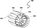
Fig. 7 A to Fig. 7 C illustrates each stage of structure of other exemplary embodiments of the outer cover that is used for wind turbine of the present invention and/or sparger.Impeller is not shown in these figure.Here, the combination 390 of outer cover/sparger comprises central portion 400 and a plurality of outer cover first rib parts 410, and central portion 400 and a plurality of outer cover first rib parts 410 define the inlet end 402 and the exhaust end 404 of turbine housing jointly.Then, cover central portions 400 and a plurality of outer cover first rib parts 410 to finish turbine housing with outer membrane material 406.The exhaust end 404 of turbine housing can have the area littler than inlet end 402.Similarly, ejector shroud comprises central portion 420 and a plurality of sparger first rib parts 430, and central portion 420 and a plurality of sparger first rib parts 430 define the inlet end 422 and the exhaust end 424 of ejector shroud jointly.Then, cover central portions 420 and a plurality of sparger first rib parts 430 to finish ejector shroud with outer membrane material 426.In certain embodiments, outer cover central portion 400 and sparger central portion 420 are connected with each other by outer cover first rib parts 410.
In other embodiment, turbine housing can comprise a plurality of outer cover second rib parts 440.Outer cover second rib parts 440 couple together outer cover central portion 400 and sparger central portion 420.Outer cover first rib parts 410 and the outer cover second rib parts 440 common a plurality of primary lobe 442 that limit exhaust end 404 places that are positioned at outer cover.Usually, outer cover first rib parts 410 have different shapes with outer cover second rib parts 440.Similarly, in other embodiment, ejector shroud can comprise a plurality of sparger second rib parts 450.Sparger first rib parts 430 and the sparger second rib parts 450 common a plurality of primary lobe 452 that limit exhaust end 424 places that are positioned at sparger.Usually, sparger first rib parts 430 have different shapes with sparger second rib parts 450.
Shown in Fig. 7 A, outer cover first rib parts 410 are connected to sparger central portion 420 with sparger first rib parts 430 in identical position.Similarly, outer cover second rib parts 440 are connected to sparger central portion 420 with sparger second rib parts 450 in identical position.Each flank spare connects optional in identical position.
As selection, shown in Fig. 7 D, outer cover/sparger combination 390 can be regarded as comprising first central portion 400, second central portion 420, a plurality of first internal rib 460 and a plurality of second internal rib 470.The combination of two central portions, first internal rib and second internal rib defines the shape of the lobe on lobe, ejector shroud and the ejector shroud on turbine housing, the turbine housing.Turbine housing is limited by the zone between two central portions 400 and 420, and simultaneously, ejector shroud is arranged on the downstream of second central portion 420.Compare with Fig. 7 A, first internal rib 460 can be regarded as the integral type combination of outer cover first rib parts 410 and sparger first rib parts 430, and second internal rib 470 can be regarded as the integral type combination of outer cover second rib parts 440 and sparger second rib parts 450 simultaneously.
Fig. 8 A to Fig. 8 C is each embodiment's the side view that is applicable to the internal rib of each embodiment shown in Fig. 7 A to Fig. 7 C.In Fig. 8 A, rib 500 comprises that integrally formed arch member 510 and landscape orientation element 520 are to form the rib that is generally rigidity together.These parts are lightweight normally, and can be considered to be the beam 502 that is linked together by pole 504.Arch member 510 defines the shape of turbine housing, and landscape orientation element 520 defines the shape of ejector shroud.
With reference to figure 8B, rib 500 comprises fixed component 530 and actuating member 540.Fixed component 530 defines the shape of turbine housing, and actuating member 540 defines the shape of ejector shroud.Fixed component 530 and actuating member 540 link together along root edge 508 by the pivot 550 that defines the angle between the two.Fixed component 530 and actuating member 540 are by sleeve pipe or linear moving member 560 and link together along apical margin 506.The two engages actuator 570 and fixed component 530 and actuating member 540 changing the angle between the two, thereby changes the shape of outer cover and/or sparger.Solid line illustrates and shortens or linear position, and is shown in dotted line elongation or oblique position.The ability of this change shape makes the whole framework of turbine housing or ejector shroud also can change/change shape.
With reference to figure 8C, fixed component 530 and actuating member 540 all link together by sleeve pipe or linear moving member 560 at apical margin 506 and root edge 508, and sleeve pipe or linear moving member 560 change the length of rib 500 together with actuator 570.
Fig. 8 D illustrates the turbo machine 580 with turbine housing 582 and ejector shroud 584.Here the flank spare of sparger (not shown) is in and shortens the position.In Fig. 8 E, the flank spare of ejector shroud is in extended position, makes sparger have bigger length and different air-flow characters.Therefore, the flexible nature of the flank spare in the wind turbine makes wind turbine can change structure to adapt to different wind conditions.
In Fig. 9, wind turbine 600 has and is depicted as the impeller that is installed on the motor 604 and is supported on the propeller cavitation 602 on the post 606.Be provided with expandable outer cover 608 around propeller cavitation 602.Therefore, inflatable outer cover can be applied to the wind turbine of existing type.
Figure 10 is an alternate embodiment, and wherein turbo machine 600 be can't help post and supported.But expandable outer cover 608 has been lighter than air such as hydrogen, helium, ammonia or methane etc. gas expands.This provides enough buoyancy for freely rising of turbo machine 600.Bolt rope or rope 610 that turbo machine 600 is connected with controller hitch, and controller can make bolt rope 610 elongate or shorten.Thereby, do not need the supporting structure except that bolt rope 610.Matrix 612 can comprise the spool or the drum of the length that is used to control bolt rope 610.Such feature can be provided in the simple quick response device that reduces turbo machine 600 under the situation of high wind speed.
Expansible elements as described herein can comprise that several are used to control the inner chamber of lifting capacity or degrees of expansion.Aptly, these inner chambers can be arranged as around expansible elements, and perhaps the end from expansible elements is arranged into the other end.
The thin-film material that is used to form the expansible elements of outer cover and/or sparger and adventitia can be basically by polymer material or web material are made arbitrarily.Typical material comprises the multilayer film of polyurethane, poly-fluoropolymer polymer and analogous components.Can also adopt such as spandex stretch fabric telescopic fabrics such as (spandex-type fabrics).
Polyurethane film is firm and have a good weathering resistance.Compare with EU, the PAUR film is responsive more to hydrophilic reduction (hydrophilic degradation).The aliphatic form of these polyurethane films (aliphatic version) also has uviolresistance usually.
Typical poly-fluoropolymer polymer comprises polyvinylidene fluoride (PVDF) and polyvinylfluoride (PVF).Commercially available form is KYNAR and TEDLAR.Poly-fluoropolymer polymer has low-down surface energy usually, and this makes compares with the material with higher surface energy, and the surface energy of poly-fluoropolymer polymer keeps not having dirt to a certain extent, no chip and easier deicing.
Also it is contemplated that with film/Fabric composites together with making expansible elements or adventitia such as bedding and padding such as foams.
Expansible elements can also be made of the urethane membrane vesicle, and capsule has the lid that strengthens the woven of its intensity and serviceability or braiding.Woven or braided material can be polyester, prestressing force polyester, polyarylate (trade name: VECTRAN
 Kuraray by Japan makes), to phenylene terephthalate amine (PpPTA) (trade name: TWARON, make by Akzo), PPTA (PPTA) (trade name: KEVLAR, make by DuPont), and PTT (trade name: CORTERRA is made by Shell).Lid woven or braiding can be covered with various polymer, such as suitable polyisoprene, polyurethane, epoxy resin or PVC.This can protection mechanism or the fiber of braiding avoid the erosion of the environment such as wearing and tearing of material that can damaged fibers such as ultraviolet ray or sand and dust or other.MANUFACTURER comprises: Federal Fabrics-Fibers of Lowell, MA; Warwick Mills of New Ipswich, NH; Vertigo lnc of Lake Elsinore, CA; With ILC Dover of Frederica, DE.Can also be by using the reactive polymer infusion process, use vacuum-assisted resin transfer method of molding (VARTM) or expansible elements being strengthened in the pre-soaked curing such as polymer such as unsaturated polyester, epoxy resin, acrylate or urethanes partially or completely, above-mentioned curing schedule causes with radiation, free radicals or isocyanate is crosslinked carries out.
The inflatable structure of the outer cover of wind turbine of the present invention and/or sparger makes turbo machine of the present invention obviously be lighter than conventional turbo machine.Thereby, can use the lower support tower of solidness.
Reference example embodiment is illustrated system and method for the present invention.Apparently, reading and understanding on the basis of above-mentioned detailed description, those skilled in the art can make amendment and modification.Exemplary embodiment should be interpreted as comprising and fall into appended claims and equivalents institute restricted portion thereof with interior all modifications and modification.
Claims (22)
1. wind turbine comprises:
Impeller; And
Turbine housing, it is provided with around described impeller, and described turbine housing comprises expansible elements.
2. wind turbine as claimed in claim 1, wherein, described turbine housing also comprises first rigid structure members, described first rigid structure members is connected to described expansible elements.
3. wind turbine as claimed in claim 2, wherein, described outer cover first rigid structure members comprises hollow inside, described outer cover expansible elements can insert in the described hollow inside.
4. wind turbine as claimed in claim 2, wherein, described outer cover first rigid structure members limits the leading edge of described turbine housing.
5. wind turbine as claimed in claim 2, wherein, described turbine housing also comprises second rigid structure members, described second rigid structure members and described outer cover first rigid structure members are connected to described outer cover expansible elements on the contrary, and described second rigid structure members limits the trailing edge of described turbine housing.
6. wind turbine as claimed in claim 5, wherein, described outer cover second rigid structure members forms, for described turbine housing is provided with a plurality of mixing lobes.
7. wind turbine as claimed in claim 1, wherein, described outer cover expansible elements forms around the trailing edge of described turbine housing a plurality of mixing lobes is set.
8. wind turbine as claimed in claim 1 also comprises ejector shroud, and described ejector shroud is set to center on coaxially described turbine housing, and described ejector shroud comprises expansible elements.
9. wind turbine as claimed in claim 8, wherein, described ejector shroud also comprises first rigid structure members, described first rigid structure members is connected to described sparger expansible elements.
10. wind turbine as claimed in claim 9, wherein, described sparger first rigid structure members comprises hollow inside, described sparger expansible elements can insert in the described hollow inside.
11. wind turbine as claimed in claim 9, wherein, described sparger first rigid structure members limits the leading edge of described ejector shroud.
12. wind turbine as claimed in claim 9, wherein, described ejector shroud also comprises second rigid structure members, described second rigid structure members and described sparger first rigid structure members are connected to described sparger expansible elements on the contrary, and described second rigid structure members limits the trailing edge of described ejector shroud.
13. wind turbine as claimed in claim 12, wherein, described sparger second rigid structure members forms, for described ejector shroud is provided with a plurality of mixing lobes.
14. wind turbine as claimed in claim 8, wherein, described sparger expansible elements is configured to when described sparger expansible elements partly expands, by the area that trailing edge defined of described sparger expansible elements less than the area that leading edge defined by described sparger expansible elements.
15. wind turbine as claimed in claim 8, wherein, described sparger expansible elements forms around the trailing edge of described ejector shroud a plurality of mixing lobes is set.
16. wind turbine as claimed in claim 1, wherein, described expansible elements has the shape of the annular wing.
17. a wind turbine comprises:
Turbine housing; And
Ejector shroud, described ejector shroud are set to coaxially around described turbine housing;
Described turbine housing comprises outer cover central portion, a plurality of outer cover first rib parts and the outer cover adventitia that engage with described outer cover central portion, wherein, described outer cover central portion and described a plurality of outer cover first rib parts limit the inlet end and the exhaust end of described turbine housing; And
Described ejector shroud comprises sparger central portion, a plurality of sparger first rib parts and the sparger adventitia that engage with described sparger central portion, and described sparger central portion and described a plurality of sparger first rib parts limit the inlet end and the exhaust end of described ejector shroud.
18. wind turbine as claimed in claim 17, wherein, described turbine housing also comprises a plurality of outer cover second rib parts, and each outer cover second rib parts extends between described outer cover central portion and described sparger central portion; And
Described a plurality of outer cover first rib parts and described a plurality of outer cover second rib parts limit a plurality of primary lobe at the exhaust end place of described turbine housing together.
19. wind turbine as claimed in claim 17, wherein, described ejector shroud also comprises a plurality of sparger second rib parts, and described sparger second rib parts engage with described sparger central portion; And
Described a plurality of sparger first rib parts and described a plurality of sparger second rib parts limit a plurality of primary lobe at the exhaust end place of described ejector shroud together.
20. wind turbine as claimed in claim 17, wherein, described sparger first rib parts comprise fixed component and actuating member, and described fixed component and described actuating member link together at the pivot place, to change the angle between described fixed component and the described actuating member.
21. wind turbine as claimed in claim 17, wherein, described sparger first rib parts comprise fixed component and actuating member, and described fixed component and described actuating member are bonded together, and the length of described sparger first rib parts can be changed.
22. a wind turbine comprises:
Impeller;
Turbine housing, described turbine housing are provided with around described impeller and have a plurality of around exhaust end and the mixing lobes that are provided with; And
Ejector shroud, described sparger is provided with around described turbine housing, and described ejector shroud comprises expansible elements.
Applications Claiming Priority (3)
| Application Number | Priority Date | Filing Date | Title |
|---|---|---|---|
| US19135808P | 2008-09-08 | 2008-09-08 | |
| US61/191,358 | 2008-09-08 | ||
| PCT/US2009/056185 WO2010028342A2 (en) | 2008-09-08 | 2009-09-08 | Inflatable wind turbine |
Publications (1)
| Publication Number | Publication Date |
|---|---|
| CN102209847A true CN102209847A (en) | 2011-10-05 |
Family
ID=41797913
Family Applications (1)
| Application Number | Title | Priority Date | Filing Date |
|---|---|---|---|
| CN2009801444492A Pending CN102209847A (en) | 2008-09-08 | 2009-09-08 | Inflatable wind turbine |
Country Status (7)
| Country | Link |
|---|---|
| EP (1) | EP2329142A4 (en) |
| JP (1) | JP2012502224A (en) |
| KR (1) | KR20110050701A (en) |
| CN (1) | CN102209847A (en) |
| AU (1) | AU2009289421A1 (en) |
| CA (1) | CA2736461A1 (en) |
| WO (1) | WO2010028342A2 (en) |
Cited By (1)
| Publication number | Priority date | Publication date | Assignee | Title |
|---|---|---|---|---|
| CN108350852A (en) * | 2015-10-14 | 2018-07-31 | 弗劳根发展管理有限责任公司 | Flow energy generation device, especially wind power generation plant |
Families Citing this family (14)
| Publication number | Priority date | Publication date | Assignee | Title |
|---|---|---|---|---|
| US8801362B2 (en) | 2007-03-23 | 2014-08-12 | Ogin, Inc. | Fluid turbine |
| US8393850B2 (en) | 2008-09-08 | 2013-03-12 | Flodesign Wind Turbine Corp. | Inflatable wind turbine |
| US8714923B2 (en) | 2007-03-23 | 2014-05-06 | Ogin, Inc. | Fluid turbine |
| EP2438297A2 (en) | 2009-06-03 | 2012-04-11 | FloDesign Wind Turbine Corp. | Inflatable wind turbine |
| WO2010141867A2 (en) * | 2009-06-04 | 2010-12-09 | Flodesign Wind Turbine Corporation | Coated shrouded wind turbine |
| AU2011329643A1 (en) * | 2010-11-19 | 2013-05-23 | Flodesign Wind Turbine Corp. | Fluid turbine |
| GB2490170B (en) * | 2011-04-21 | 2014-06-11 | Anakata Wind Power Resources S A R L | A horizontal axis wind turbine with diffuser |
| US8672624B2 (en) * | 2011-04-27 | 2014-03-18 | SkyWolf Wind Turbine Corp. | High efficiency wind turbine having increased laminar airflow |
| US8851836B2 (en) | 2011-04-27 | 2014-10-07 | SkyWolf Wind Turbine Corp. | High efficiency wind turbine including photovoltaic cells |
| US9322391B2 (en) | 2011-04-27 | 2016-04-26 | SkyWolf Wind Turbine Corp. | Housing for a high efficiency wind turbine |
| US8721279B2 (en) | 2011-04-27 | 2014-05-13 | SkyWolf Wind Turbines Corp. | Multiple mixing internal external fluid driven high efficiency wind turbine having reduced downstream pressure |
| JP2013096403A (en) * | 2011-11-01 | 2013-05-20 | Yaheitai Hayashi | Outdoor facility device enabling columnar multi-connection installation by providing buoyancy (specific weight) regulation function and fluid direction guide function for turbine (water turbine, wind turbine) installed in fluid for power generation (power) |
| GB201700675D0 (en) * | 2017-01-14 | 2017-03-01 | Lewis Stephen Desmond | Reduced cost wind power generator |
| DK3473848T3 (en) | 2017-10-20 | 2022-12-12 | Flowgen Development & Man Ag | FLOW ENERGY PLANT, ESPECIALLY CAPE WIND TURBINE |
Citations (5)
| Publication number | Priority date | Publication date | Assignee | Title |
|---|---|---|---|---|
| US4166596A (en) * | 1978-01-31 | 1979-09-04 | Mouton William J Jr | Airship power turbine |
| CN2073944U (en) * | 1990-07-04 | 1991-03-27 | 南京航空学院 | Wind-driven generator |
| US5669758A (en) * | 1996-01-24 | 1997-09-23 | Williamson; Larry D. | Wind turbine |
| US5761900A (en) * | 1995-10-11 | 1998-06-09 | Stage Iii Technologies, L.C. | Two-stage mixer ejector suppressor |
| US6382904B1 (en) * | 1998-03-25 | 2002-05-07 | Igor Sergeevich Orlov | Windmill powerplant |
Family Cites Families (6)
| Publication number | Priority date | Publication date | Assignee | Title |
|---|---|---|---|---|
| JPS50128032A (en) * | 1974-03-29 | 1975-10-08 | ||
| JPS5449433U (en) * | 1977-09-14 | 1979-04-05 | ||
| JPS54180852U (en) * | 1978-06-12 | 1979-12-21 | ||
| JPS5751967A (en) * | 1980-07-26 | 1982-03-27 | Gilchrist Timothy M | Wind force turbine construction |
| US7220096B2 (en) * | 2004-03-16 | 2007-05-22 | Tocher Angus J | Habitat friendly, multiple impellor, wind energy extraction |
| US20080048453A1 (en) * | 2006-07-31 | 2008-02-28 | Amick Douglas J | Tethered Wind Turbine |
-
2009
- 2009-09-08 EP EP09812361.5A patent/EP2329142A4/en not_active Withdrawn
- 2009-09-08 KR KR1020117007265A patent/KR20110050701A/en not_active Application Discontinuation
- 2009-09-08 JP JP2011526263A patent/JP2012502224A/en active Pending
- 2009-09-08 CN CN2009801444492A patent/CN102209847A/en active Pending
- 2009-09-08 WO PCT/US2009/056185 patent/WO2010028342A2/en active Application Filing
- 2009-09-08 AU AU2009289421A patent/AU2009289421A1/en not_active Abandoned
- 2009-09-08 CA CA2736461A patent/CA2736461A1/en not_active Abandoned
Patent Citations (5)
| Publication number | Priority date | Publication date | Assignee | Title |
|---|---|---|---|---|
| US4166596A (en) * | 1978-01-31 | 1979-09-04 | Mouton William J Jr | Airship power turbine |
| CN2073944U (en) * | 1990-07-04 | 1991-03-27 | 南京航空学院 | Wind-driven generator |
| US5761900A (en) * | 1995-10-11 | 1998-06-09 | Stage Iii Technologies, L.C. | Two-stage mixer ejector suppressor |
| US5669758A (en) * | 1996-01-24 | 1997-09-23 | Williamson; Larry D. | Wind turbine |
| US6382904B1 (en) * | 1998-03-25 | 2002-05-07 | Igor Sergeevich Orlov | Windmill powerplant |
Cited By (1)
| Publication number | Priority date | Publication date | Assignee | Title |
|---|---|---|---|---|
| CN108350852A (en) * | 2015-10-14 | 2018-07-31 | 弗劳根发展管理有限责任公司 | Flow energy generation device, especially wind power generation plant |
Also Published As
| Publication number | Publication date |
|---|---|
| JP2012502224A (en) | 2012-01-26 |
| CA2736461A1 (en) | 2010-03-11 |
| WO2010028342A2 (en) | 2010-03-11 |
| KR20110050701A (en) | 2011-05-16 |
| AU2009289421A1 (en) | 2010-03-11 |
| EP2329142A2 (en) | 2011-06-08 |
| WO2010028342A3 (en) | 2010-07-15 |
| EP2329142A4 (en) | 2014-01-01 |
Similar Documents
| Publication | Publication Date | Title |
|---|---|---|
| CN102209847A (en) | Inflatable wind turbine | |
| US8393850B2 (en) | Inflatable wind turbine | |
| AU2010232745B2 (en) | Segmented wind turbine | |
| US20100284802A1 (en) | Inflatable wind turbine | |
| US4547124A (en) | Impeller for a wind motor | |
| CN1904353B (en) | Methods and apparatus for reducing load in a rotor blade | |
| US8668455B2 (en) | Turbine wheel | |
| EP2483554B1 (en) | Tapered hollow helical turbine for energy transduction | |
| US20100143130A1 (en) | Inflatable wind turbine blade and method for forming said rotor blade | |
| MXPA06012386A (en) | Methods of making wind turbine rotor blades. | |
| WO2007084447A2 (en) | Wind turbine | |
| CN102202964A (en) | Systems and methods for protecting a wind turbine in high wind conditions | |
| CN102597502A (en) | Inflatable wind turbine | |
| US20110250053A1 (en) | Fluid turbines | |
| US20110014038A1 (en) | Wind turbine with skeleton-and-skin structure | |
| US20080317582A1 (en) | Vertical axis dual vortex downwind inward flow impulse wind turbine | |
| US8647050B2 (en) | Variable partial wind wall | |
| US8556586B2 (en) | Turbine blade | |
| RU2807846C1 (en) | Horizontal conical sail windmill | |
| CN111852759A (en) | Airflow flow adjusting device and power generation device |
Legal Events
| Date | Code | Title | Description |
|---|---|---|---|
| C06 | Publication | ||
| PB01 | Publication | ||
| C10 | Entry into substantive examination | ||
| SE01 | Entry into force of request for substantive examination | ||
| REG | Reference to a national code |
Ref country code: HK Ref legal event code: DE Ref document number: 1162637 Country of ref document: HK |
|
| C12 | Rejection of a patent application after its publication | ||
| RJ01 | Rejection of invention patent application after publication |
Application publication date: 20111005 |
|
| REG | Reference to a national code |
Ref country code: HK Ref legal event code: WD Ref document number: 1162637 Country of ref document: HK |