JP2012205784A - Biological signal measurement device, bed for biological signal measurement, and biological signal measurement method - Google Patents
Biological signal measurement device, bed for biological signal measurement, and biological signal measurement method Download PDFInfo
- Publication number
- JP2012205784A JP2012205784A JP2011073940A JP2011073940A JP2012205784A JP 2012205784 A JP2012205784 A JP 2012205784A JP 2011073940 A JP2011073940 A JP 2011073940A JP 2011073940 A JP2011073940 A JP 2011073940A JP 2012205784 A JP2012205784 A JP 2012205784A
- Authority
- JP
- Japan
- Prior art keywords
- electrode
- signal
- biological signal
- electrodes
- ground
- Prior art date
- Legal status (The legal status is an assumption and is not a legal conclusion. Google has not performed a legal analysis and makes no representation as to the accuracy of the status listed.)
- Granted
Links
Images


Landscapes
- Measurement Of The Respiration, Hearing Ability, Form, And Blood Characteristics Of Living Organisms (AREA)
- Measurement And Recording Of Electrical Phenomena And Electrical Characteristics Of The Living Body (AREA)
Abstract
Description
本発明は、生体信号測定装置、生体信号測定用ベッド、及び、生体信号測定方法に関する。 The present invention relates to a biological signal measuring device, a biological signal measuring bed, and a biological signal measuring method.
心電信号や呼吸情報などの生体情報を測定することで、疾病の早期発見や予防、健康の維持・管理、治療効果の評価や確認などが行われている。 By measuring biological information such as electrocardiogram signals and respiratory information, early detection and prevention of diseases, maintenance and management of health, and evaluation and confirmation of therapeutic effects are performed.
家庭内で生体情報をモニタリングするための市販の装置としては、粘着性の電極を皮膚に接着し、心拍と呼吸性変動をモニタリングするものがある。しかしながら粘着性の電極を用いた場合、長期モニタリングにおける皮膚への負担が大きく、かぶれや炎症などを引き起こすほか、電極交換時に皮膚が剥離する恐れがある。 As a commercially available apparatus for monitoring biological information at home, there is an apparatus that adheres an adhesive electrode to the skin and monitors heartbeat and respiratory fluctuation. However, when sticky electrodes are used, the burden on the skin during long-term monitoring is great, causing rashes and irritation, and there is a risk of skin peeling when the electrodes are replaced.
そこで、本発明者らは、容量性結合の原理を応用し、市販の布を介して四肢から心電図を計測する手段を発明し、2004年に発表した(非特許文献1)。 Therefore, the present inventors invented a means for measuring an electrocardiogram from the extremities via a commercially available cloth by applying the principle of capacitive coupling, and published in 2004 (Non-patent Document 1).
また、本発明者らは、ベッドシーツの下の適切な位置(肩胛骨裏側付近)に導電性布の電極を設置し、仰臥位の成人被験者から第II誘導と類似した心電図波形を計測する手段を発明し、2007年4月に発表した(非特許文献2)。 The present inventors also provided means for measuring an electrocardiogram waveform similar to the lead II from a supine adult subject by placing an electrode of a conductive cloth at an appropriate position (near the back side of the shoulder rib) under the bed sheet. Invented and published in April 2007 (Non-Patent Document 2).
また、本発明者らは、(1)パジャマとシーツを介して心電図波形を計測する手段、(2)帯状布電極を使用することで、仰臥位だけでなく側臥位でも計測可能とする手段、及び、(3)フィルタの通過帯域を5−40Hzに狭めることで、体動の少ない睡眠状態では100%に近いR波検出率を期待できる手段を発明し、2007年10月に発表した(非特許文献3)。 In addition, the present inventors have (1) a means for measuring an electrocardiogram waveform through pajamas and sheets, and (2) a means for enabling measurement not only in a supine position but also in a lateral position by using a belt-like cloth electrode, And (3) By inventing a means that can expect an R wave detection rate close to 100% in a sleep state with little body movement by narrowing the pass band of the filter to 5-40 Hz, it was announced in October 2007 (non- Patent Document 3).
さらに、本発明者らは、布製電極を設置したマットレスに市販の肌着を着た乳児を寝かせた状態で、狭帯域心電図と呼吸情報を同時に計測する手段を発明し、2009年2月に発表した(非特許文献4)。 Furthermore, the present inventors invented a means for simultaneously measuring a narrow-band electrocardiogram and respiratory information in a state in which an infant wearing a commercial underwear is laid on a mattress provided with a cloth electrode, and announced in February 2009. (Non-Patent Document 4).
非特許文献4に記載の技術では、3つの電極を用意し、布を介して1つの電極を被験者の臀部に接触させ、当該電極をグランドとし、同様に布を介して残り2つの電極を被験者の胸背部及び腹背部各々に接触させて差動用電極として用い、分離フィルタにより心電信号と呼吸情報を各1種類ずつ同時に計測する。 In the technique described in Non-Patent Document 4, three electrodes are prepared, one electrode is brought into contact with the subject's buttocks through a cloth, the electrode is used as a ground, and the remaining two electrodes are similarly formed through the cloth. This is used as a differential electrode in contact with each of the chest back and abdominal back, and an electrocardiogram signal and respiratory information are simultaneously measured by a separation filter.
しかし、非特許文献4に記載の技術の場合、心電信号と呼吸情報を同時に測定することはできるが、測定精度の面で改良の余地があった。すなわち、同時に測定した生体信号(心電信号と呼吸情報)の内、一方の測定精度が不十分になる場合があった。 However, in the case of the technique described in Non-Patent Document 4, an electrocardiogram signal and respiratory information can be measured simultaneously, but there is room for improvement in terms of measurement accuracy. That is, the measurement accuracy of one of the biological signals (electrocardiogram signal and respiratory information) measured at the same time may be insufficient.
そこで、本発明では、3つの電極を用いて、心電信号及び呼吸情報を、いずれも十分な精度で、同時に測定する手段を提供することを課題とする。 Accordingly, an object of the present invention is to provide means for simultaneously measuring an electrocardiogram signal and respiratory information with sufficient accuracy using three electrodes.
本発明によれば、第1乃至第3の電極と、前記第1乃至第3の電極各々とコンデンサ又は抵抗を介して繋がったグランドと、前記第1の電極からの信号及び前記第3の電極からの信号各々が、バッファを介して入力されるとともに、前記グランドが回路のグランドとして接続される第1の分離回路と、前記第2の電極からの信号及び前記第3の電極からの信号各々が、バッファを介して入力されるとともに、前記グランドが回路のグランドとして接続される第2の分離回路と、を有し、前記第1及び第2の分離回路は、入力された信号を、呼吸成分と心電図成分に分離する分離フィルタを有する生体信号測定装置が提供される。 According to the present invention, the first to third electrodes, the ground connected to each of the first to third electrodes via a capacitor or a resistor, the signal from the first electrode, and the third electrode Are input through a buffer, and each of the signals from the second electrode and the third electrode is connected to the first separation circuit in which the ground is connected as the circuit ground. And a second separation circuit to which the ground is connected as a circuit ground, and the first and second separation circuits are configured to breathe input signals. A biological signal measuring device having a separation filter for separating a component and an electrocardiogram component is provided.
また、本発明によれば、第1乃至第3の電極と、前記第1乃至第3の電極各々とコンデンサ又は抵抗を介して繋がったグランドと、前記第1の電極からの信号及び前記第3の電極からの信号各々が、バッファを介して入力されるとともに、前記グランドが回路のグランドとして接続される第1の分離回路と、前記第2の電極からの信号及び前記第3の電極からの信号各々が、バッファを介して入力されるとともに、前記グランドが回路のグランドとして接続される第2の分離回路と、を有し、前記第1及び第2の分離回路は、入力された信号を、第1の周波数帯と第2の周波数帯に分離する分離フィルタを有する生体信号測定装置が提供される。 According to the present invention, the first to third electrodes, the ground connected to each of the first to third electrodes via a capacitor or a resistor, the signal from the first electrode, and the third Each of the signals from the first electrode is input through a buffer, and the first separation circuit to which the ground is connected as the ground of the circuit, the signal from the second electrode, and the third electrode Each of the signals is input via a buffer, and the ground is connected as a circuit ground. The second separation circuit is connected to the circuit, and the first and second separation circuits receive the input signal. A biological signal measuring device having a separation filter that separates into a first frequency band and a second frequency band is provided.
また、本発明によれば、上記生体信号測定装置いずれかを備える生体信号測定用ベッドが提供される。 Moreover, according to this invention, the bed for biological signal measurement provided with either of the said biological signal measuring apparatuses is provided.
また、本発明によれば、上記生体信号測定用ベッドを利用した生体信号測定方法であって、前記マットレスにシーツを被せ、前記第1乃至第3の電極を前記シーツで覆った状態で、その上に被験者が横になり、生体信号を測定する生体信号測定方法が提供される。 Further, according to the present invention, there is provided a biological signal measurement method using the biological signal measurement bed, wherein the mattress is covered with a sheet, and the first to third electrodes are covered with the sheet. A biological signal measurement method is provided in which a subject lies on top and measures a biological signal.
本発明によれば、3つの電極を用いて、心電信号及び呼吸情報を、いずれも十分な精度で、同時に測定することが可能となる。 According to the present invention, it is possible to simultaneously measure an electrocardiogram signal and respiratory information with sufficient accuracy using three electrodes.
以下、本発明の実施形態を図面に基づいて説明する。なお、すべての図面において、同様な構成要素には同様の符号を付し、適宜説明を省略する。 Hereinafter, embodiments of the present invention will be described with reference to the drawings. In all the drawings, the same reference numerals are given to the same components, and the description will be omitted as appropriate.
図1に、本実施形態の生体信号測定装置を有する生体信号測定用ベッドのブロック図の一例を示す。 FIG. 1 shows an example of a block diagram of a biological signal measuring bed having the biological signal measuring apparatus of the present embodiment.
本実施形態の生体信号測定装置は、第1の電極11、第2の電極12、第3の電極13、バッファ17乃至19、コンデンサ20乃至22、グランド16、第1の分離回路14及び第2の分離回路15を有する。そして、第1の電極11、第2の電極12及び第3の電極13が、マットレス24の上に位置する。
The biological signal measuring device of this embodiment includes a
第1乃至第3の電極11乃至13は、心電図の測定等に用いられるあらゆる電極を適用することができ、例えば布製の電極とすることができる。
As the first to
第1の電極11は、絶縁物、例えば布を介して、被験者(人体)の胸背部と接触する。第2の電極12は、絶縁物、例えば布を介して、被験者(人体)の腹背部と接触する。第3の電極13は、絶縁物、例えば布を介して、被験者(人体)の臀部と接触する。
The
例えば、第1乃至第3の電極11乃至13は、図1に示すようにマットレス24の上に露出するように配置される。そして、マットレス24に被せられたベッドシーツ(図示せず)により、第1乃至第3の電極11乃至13は、ベッドシーツに覆われた状態となる。当該状態のマットレス24の上に被験者が横になることで、第1乃至第3の電極11乃至13は、ベッドシーツ(絶縁物)を介して被験者(人体)と接触することとなる。なお、第1乃至第3の電極11乃至13は、ベッドシーツに加えて(又は代えて)、被験者が着ている着衣(絶縁物)を介して、被験者(人体)と接触してもよい。ベッドシーツは市販のものを使用することができる。また、着衣も市販のものを使用できるが、薄手の着衣であるのが好ましい。第1乃至第3の電極11乃至13は、マットレス24に埋め込まれていてもよいし、マットレス24から取り外し可能に構成されていてもよい。後者の場合、マットレス24上における第1乃至第3の電極11乃至13の配置位置を調整することができる。
For example, the first to
ここで、図2に、第1乃至第3の電極11乃至13及びマットレス24の平面概略図の一例を示す。
Here, FIG. 2 shows an example of a schematic plan view of the first to
第1乃至第3の電極11乃至13は、被験者がマットレス24の上に横になった状態に合わせて、所定の位置に配置される。具体的には、第1の電極11は、マットレス24の上に横になった被験者の胸背部付近、第2の電極12は腹背部付近、第3の電極13は臀部付近に配置される。図示する「Head」及び「Breech」は、横になった被験者の頭の位置及び臀部の位置を示している。なお、被験者の体格に応じて胸部、腹部及び臀部の位置は変わるので、第1乃至第3の電極11乃至13はマットレス24から取り外し可能に構成されていると有益である。かかる場合、被験者の体格に応じて、第1乃至第3の電極11乃至13の配置位置を適切な位置に変更できる。
The first to
第1及び第2の電極11及び12は、例えば図示するような帯状であってもよい。そして、このような形状の第1及び第2の電極11及び12は、横になった状態の被験者の頭と足先を結ぶ直線と垂直に伸びるように配置されてもよい。このように構成すれば、被験者が寝返りをうっても、被験者と、第1及び第2の電極11及び12との接触状態を維持させることができる。なお、第1及び第2の電極11及び12は図示するような直線状に限定されず、波線状、ジグザグ線状等その他の形状であってもよい。
The first and
第3の電極13の形状は、上述した第1及び第2の電極11及び12と同じものにすることも可能であるが、図示するように、2本の直線状の電極が連結してV字形状を形成したものであってもよい。そして、V字形状の上記連結部分を被験者の臀部付近に配置し、連結部分から伸びる電極が被験者の足方向に伸びるように配置してもよい。このようにすれば被験者の手が、第3の電極13に触れる不都合を抑制することができる。なお、連結部分の角度は例えば90度とすることができる。また、連結部分から伸びる電極は、図示するような直線状に限定されず、波線状、ジグザグ線状等その他の形状であってもよい。
The shape of the
図1に戻り、バッファ17乃至19は、インピーダンスを変換する機能を有し、例えば、1000GΩ程度の入力抵抗のICを適用することができる。バッファ17乃至19各々には、第1乃至第3の電極11乃至13各々から信号が入力される。
Returning to FIG. 1, the
グランド16は、第1乃至第3の電極11乃至13各々と、コンデンサ20乃至22各々を介して繋がっている。例えば、図示するように第1乃至第3の電極11乃至13をコンデンサ20乃至22各々経由で結合し、当該結合点を仮想的なグランド16とすることができる。なお、図示する例では、グランド16は、コンデンサ20乃至22に加えてバッファ17乃至19をも経由して第1乃至第3の電極11乃至13と繋がっているが、バッファ17乃至19を経由しない構成とすることもできる。すなわち、図示する23の破線で囲まれた構成要素(コンデンサ20乃至23、及び、グランド16)を、第1乃至第3の電極11乃至13と、バッファ17乃至19との間に位置させることもできる。なお、23の破線で囲まれた構成要素を図示する位置に配置する場合、コンデンサ20乃至22に代えて、抵抗を適用することも可能である。
The
第1の分離回路14には、第1の電極11からの信号及び第3の電極13からの信号各々が、バッファ17及び19各々を介して入力される。第2の分離回路15には、第2の電極12からの信号及び第3の電極13からの信号各々が、バッファ18及び19各々を介して入力される。また、図示しないが、第1の分離回路14及び第2の分離回路15には、グランド16の信号が入力される。
A signal from the
第1及び第2の分離回路14及び15は、回路のグランドとして接続されたグランド16から混入する雑音を利用して、第1乃至第3の電極11乃至13各々から入力された信号から商用電源雑音(同相雑音)を除去する。当該処理は、従来技術に準じて実現できる。
The first and
また、第1及び第2の分離回路14及び15は、第1乃至第3の電極11乃至13から入力された信号を、呼吸成分と心電図成分に分離する分離フィルタを有する。分離フィルタは、例えば、入力された信号を、第1の周波数帯と第2の周波数帯に分離する。心電図成分(R波)の帯域は、10Hz以上100Hz以下程度、呼吸成分の帯域は0.1Hz以上1Hz以下程度である。そこで、当該分離フィルタでは、1Hz以上10Hz以下の間の所定値を境目とし、当該所定位置以上の帯域を第1の周波数帯(心電図成分)、当該所定値未満の帯域を第2の周波数帯(呼吸成分)として分離する。当該所定値は、例えば1Hzとすることができる。
The first and
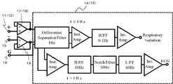
ここで、図3を用いて、第1及び第2の分離回路14及び15の構成の一例を説明する。図示するブロック図は、第1及び第3の電極11及び13と、グランド16と、バッファ17及び19と、第1分離回路14とを示している。第1分離回路14は、「Differential Separation Filter(差動分離フィルタ)」、「Inst.Amp.(計装増幅器)」、「H.P.F.(ハイパスフィルタ)」、「Inv.Amp.(反転増幅器)」、「L.P.F.(ロ−パスフィルタ)」、及び、「Notch Filter(ノッチフィルタ)」を有する。なお、図示するブロック図において、第1の電極11を第2の電極12とみなし、バッファ17をバッファ18とみなし、第1分離回路14を第2分離回路15とみなすこともできる。
Here, an example of the configuration of the first and
図3に示すように、第1及び第3の電極11及び13各々から、バッファ17及び19各々に信号が入力される。以下、第1の電極11から入力された信号を「第1の電極11の信号」、第3の電極13から入力された信号を「第3の電極13の信号」という。バッファ17及び19は、例えば1000GΩ程度の入力抵抗のオペアンプICである。そして、バッファ17及び19から、「Differential Separation Filter(差動分離フィルタ)」に信号が入力される。また、グランド16から、「Differential Separation Filter(差動分離フィルタ)」に商用電源雑音などの同相雑音が混入する。
As shown in FIG. 3, signals are input to the
「Differential Separation Filter(差動分離フィルタ)」には、バッファ17及び19から信号が入力され、グランド16から同相雑音が混入する。そして、「Differential Separation Filter(差動分離フィルタ)」は、第1の電極11の信号及び第3の電極13の信号から商用電源雑音(同相雑音)を除去すると共に、第1の電極11の信号及び第3の電極13の信号の差動成分を、例えば1Hz以上の第1の周波数帯(心電図成分)と、1Hz未満の第2の周波数帯(呼吸成分)に分離する。図4に、「Differential Separation Filter(差動分離フィルタ)」のブロック図の一例を示す。当該図に示すように、「Differential Separation Filter(差動分離フィルタ)」によれば、1つの入力から、「H.P.F.(ハイパスフィルタ)」と「L.P.F.(ローパスフィルタ」)」の2つの伝達関数の出力が得られることが分かる。
In the “Differential Separation Filter”, signals from the
図3に戻り、1つの「Inst.Amp.(計装増幅器)」には、第1の電極11の信号及び第3の電極13の信号の差動成分から取り出された心電図成分の信号が、「Differential Separation Filter(差動分離フィルタ)」から入力される。他の「Inst.Amp.(計装増幅器)」には、第1の電極11の信号及び第3の電極13の信号の差動成分から取り出された呼吸成分の信号が、「Differential Separation Filter(差動分離フィルタ)」から入力される。「Inst.Amp.(計装増幅器)」は、入力された第1の電極11の信号及び第3の電極13の信号の差分を増幅する。
Returning to FIG. 3, in one “Inst. Amp.” (Instrumentation amplifier), the signal of the electrocardiogram component extracted from the differential component of the signal of the
「H.P.F.(ハイパスフィルタ)」には、「Inst.Amp.(計装増幅器)」から差分増幅後の信号が入力される。そして、呼吸成分の信号を入力された「H.P.F.(ハイパスフィルタ)」は、入力された信号から、例えば0.1Hz未満の周波数帯を取り除く。一方、心電図成分の信号を入力された「H.P.F.(ハイパスフィルタ)」は、入力された信号から、例えば10Hz未満の周波数帯を取り除く。 “H.P.F. (High Pass Filter)” receives a signal after differential amplification from “Inst. Amp. (Instrumentation Amplifier)”. “H.P.F. (High Pass Filter)” to which the respiratory component signal is input removes a frequency band of, for example, less than 0.1 Hz from the input signal. On the other hand, “H.P.F.” (high pass filter) to which an ECG component signal is input removes a frequency band of, for example, less than 10 Hz from the input signal.
「Notch Filter(ノッチフィルタ)」には、「H.P.F.(ハイパスフィルタ)」から10Hz未満の周波数帯を取り除いた心電図成分の信号が入力される。そして、「Notch Filter(ノッチフィルタ)」は、測定を行っている地域に応じて、入力された信号から所定の成分を取り除く。例えば測定を行っている地域が関東エリアの場合、「Notch Filter(ノッチフィルタ)」は、入力された信号から、50Hz近傍の周波数帯を取り除く。 The “Notch Filter” is input with an ECG component signal obtained by removing a frequency band of less than 10 Hz from “H.P.F. (High Pass Filter)”. The “Notch Filter” removes a predetermined component from the input signal according to the area where the measurement is performed. For example, when the region where measurement is performed is the Kanto area, “Notch Filter” removes a frequency band near 50 Hz from the input signal.
「L.P.F.(ローパスフィルタ)」には、「Notch Filter(ノッチフィルタ)」から、50Hz近傍の周波数帯を取り除いた心電図成分の信号が入力される。そして、「L.P.F.(ローパスフィルタ)」は、入力された信号から、例えば40Hz以上の周波数帯を取り除く。 “L.P.F. (low-pass filter)” is input with an ECG component signal obtained by removing a frequency band near 50 Hz from “Notch Filter”. “L.P.F. (low-pass filter)” removes a frequency band of, for example, 40 Hz or more from the input signal.
1つの「Inv.Amp.(反転増幅器)」には、「H.P.F.(ハイパスフィルタ)」から呼吸成分の信号が入力される。他の「Inv.Amp.(反転増幅器)」には、「L.P.F.(ローパスフィルタ)」から心電図成分の信号が入力される。そして、Inv.Amp.(反転増幅器)は入力された信号を増幅する。増幅度は、例えば1000倍としてもよい。 One “Inv.Amp.” (Inverted amplifier) receives a respiratory component signal from “H.P.F.”. The other “Inv.Amp.” (Inverting amplifier) receives the ECG component signal from “L.P.F.” (low-pass filter). Inv. Amp. (Inverting amplifier) amplifies the input signal. The amplification degree may be 1000 times, for example.
なお、図3に示す第1及び第2の分離回路14及び15の構成はあくまで一例であり、その他の構成とすることもできる。
Note that the configurations of the first and
次に、本実施形態の作用効果について説明する。 Next, the effect of this embodiment is demonstrated.
(1)まず、本実施形態の生体信号測定装置の測定原理について簡単に説明する。 (1) First, the measurement principle of the biological signal measuring apparatus of this embodiment will be briefly described.
図5に、本実施形態の生体信号測定装置が利用する容量性結合のモデル図と等価回路を示す。図示するように、本実施形態の場合、第1乃至第3の電極11乃至13(図中、「Fabric electrode」)は、衣服等の絶縁物(図中、「clothes」)を介して、人体(図中、「Skin」)と接触する。当該構成の場合、人体(導体)−衣服等(絶縁物)−第1乃至第3の電極11乃至13(導体)の結合により、コンデンサが形成される。以下、人体(導体)−衣服(絶縁物)−第1乃至第3の電極11乃至13(導体)がこのように結合した部分を「結合部」とよぶ。本実施形態では、結合部の静電容量を通じて、交流生体信号の導出を行っている。
FIG. 5 shows a model diagram of capacitive coupling and an equivalent circuit used by the biological signal measuring apparatus of the present embodiment. As shown in the figure, in the case of the present embodiment, the first to
次に、図6を用いて、呼吸成分の計測の原理を説明する。本実施形態の場合、呼吸に伴う被験者の胸部及び腹部等の動きにより、結合部の圧が変化する。そして、結合部の圧の変化に伴い衣服等(絶縁物)の厚みが変わると、結合部の容量値が変化する。すなわち、呼吸性変動が基線変動として出力電圧に重畳する。 Next, the principle of measurement of the respiratory component will be described with reference to FIG. In the case of the present embodiment, the pressure at the joint changes due to movement of the subject's chest and abdomen accompanying breathing. And if the thickness of clothes etc. (insulator) changes with the change of the pressure of a joint part, the capacity value of a joint part will change. That is, the respiratory change is superimposed on the output voltage as a baseline change.
なお、これらの詳細は、非特許文献1乃至4に記載されている。
These details are described in
(2)次に、図7に、本実施形態の生体信号測定用ベッドと市販の装置を同時に用いて、心電図成分の信号と呼吸成分の信号を同時に測定したデータを示す。 (2) Next, FIG. 7 shows data obtained by simultaneously measuring a signal of an electrocardiogram component and a signal of a respiratory component using the biological signal measurement bed of this embodiment and a commercially available device at the same time.
図中「(b)心電:胸部(試作装置)」として示すデータが、本実施形態の生体信号測定用ベッドを用い、第1の電極(胸部付近に配置)及び第3の電極(臀部付近に配置)を用いて検出した心電図成分の信号であり、「(e)呼吸:胸部(試作装置)」として示すデータが、第1の電極(胸部付近に配置)及び第3の電極(臀部付近に配置)を用いて検出した呼吸成分の信号である。 The data shown as “(b) electrocardiogram: chest (prototype device)” in the figure uses the biological signal measurement bed of this embodiment, and the first electrode (arranged near the chest) and the third electrode (near the buttocks) Is a signal of an electrocardiogram component detected by using the first electrode (arranged in the vicinity of the chest) and the third electrode (in the vicinity of the buttocks). Is a signal of a respiratory component detected by using (1).
また、図中「(c)心電:腹部(試作装置)」として示すデータが、本実施形態の生体信号測定用ベッドを用い、第2の電極(腹部付近に配置)及び第3の電極(臀部付近に配置)を用いて検出した心電図成分の信号であり、「(f)呼吸:腹部(試作装置)」として示すデータが、本実施形態の生体信号測定用ベッドを用い、第2の電極(腹部付近に配置)及び第3の電極(臀部付近に配置)を用いて検出した呼吸成分の信号である。 In addition, data shown as “(c) electrocardiogram: abdomen (prototype device)” in the drawing uses the biological signal measurement bed of this embodiment, and the second electrode (arranged in the vicinity of the abdomen) and the third electrode ( The signal of the electrocardiogram component detected by using the biological signal measurement bed of the present embodiment is the second electrode, and is the signal of the electrocardiogram component detected by using the biological signal measurement bed of the present embodiment. It is the signal of the respiratory component detected using (placed near the abdomen) and the third electrode (placed near the buttocks).
また、図中「(a)心電:市販装置」として示すデータが、市販の心電計で測定した心電図成分の信号であり、「(d)呼吸:市販装置」として示すデータが、市販の呼吸トランスデューサを用いて測定した呼吸成分の信号である。 In addition, the data shown as “(a) ECG: commercially available device” in the figure is a signal of an ECG component measured by a commercially available electrocardiograph, and the data shown as “(d) Respiration: commercially available device” is commercially available. It is the signal of the respiratory component measured using the respiratory transducer.
図示するように、「(b)心電:胸部(試作装置)」として示すデータが、「(a)心電:市販装置」として示すデータとほぼ同期していることが分かる。なお、「(c)心電:腹部(試作装置)」の測定精度は、「(b)心電:胸部(試作装置)」の測定精度に比べて劣ることが分かる。 As shown in the drawing, it can be seen that the data shown as “(b) ECG: chest (prototype device)” is almost synchronized with the data shown as “(a) ECG: commercial device”. It can be seen that the measurement accuracy of “(c) electrocardiogram: abdomen (prototype device)” is inferior to the measurement accuracy of “(b) electrocardiogram: chest (prototype device)”.
また、「(f)呼吸:腹部(試作装置)」として示すデータの波形が、「(d)呼吸:市販装置」として示すデータの波形とよく類似していることが分かる。なお、「(e)呼吸:胸部(試作装置)」として示すデータの波形は、「(d)呼吸:市販装置」として示すデータの波形と比較的類似しているが、「(f)呼吸:腹部(試作装置)」の測定精度に比べて劣ることが分かる。 It can also be seen that the waveform of the data shown as “(f) Respiration: Abdomen (prototype device)” is very similar to the waveform of the data shown as “(d) Respiration: Commercial device”. The waveform of the data shown as “(e) Breathing: Chest (prototype device)” is relatively similar to the waveform of the data shown as “(d) Breathing: Commercial device”, but “(f) Breathing: It can be seen that the measurement accuracy of the abdomen (prototype device) is inferior.
以上の結果から、本実施形態の測定原理を利用して心電図成分及び呼吸成分の信号を十分な測定精度で測定するためには、心電図成分の測定及び呼吸成分の測定各々、用いる電極の好ましい組み合わせがあることが分かる。すなわち、心電図成分の測定には、第1の電極(胸部付近に配置)及び第3の電極(臀部付近に配置)の組み合わせが好ましい。一方、呼吸成分の測定には、第2の電極(腹部付近に配置)及び第3の電極(臀部付近に配置)の組み合わせが好ましい。 From the above results, in order to measure the ECG component and respiratory component signals with sufficient measurement accuracy using the measurement principle of the present embodiment, preferred combinations of electrodes used for the measurement of the ECG component and the respiratory component respectively. I understand that there is. That is, for the measurement of the electrocardiogram component, a combination of the first electrode (arranged near the chest) and the third electrode (arranged near the buttocks) is preferable. On the other hand, for the measurement of the respiratory component, a combination of the second electrode (arranged near the abdomen) and the third electrode (arranged near the buttocks) is preferable.
しかし、非特許文献4に記載の技術の場合、本実施形態と同様に3つの電極を用いているものの、1つの電極をグランドとし、残り2つの電極のみを差動用電極として用いているため、上述のような心電図成分の測定に好ましい作動用電極の組み合わせ、及び、呼吸成分の測定に好ましい差動用電極の組み合わせを同時に実現することができなかった。 However, in the case of the technique described in Non-Patent Document 4, although three electrodes are used as in the present embodiment, one electrode is used as a ground and only the remaining two electrodes are used as differential electrodes. The combination of the working electrodes preferable for the measurement of the electrocardiogram component as described above and the combination of the differential electrodes preferable for the measurement of the respiratory component cannot be realized at the same time.
これに対し、本実施形態では、3つの電極を結合して結合点をグランドとし、3つの電極すべてを差動用電極として用いることができるので、上述のような心電図成分の測定に好ましい電極の組み合わせ、及び、呼吸成分の測定に好ましい差動用電極の組み合わせを同時に実現することができる。結果、3つの電極を用いて、心電図成分の信号及び呼吸成分の信号、いずれも十分な精度で、同時に測定することが可能となる。 On the other hand, in the present embodiment, the three electrodes can be combined to make the coupling point the ground, and all the three electrodes can be used as differential electrodes. Therefore, the preferred electrode for the measurement of the electrocardiogram component as described above can be used. A combination and a combination of differential electrodes preferable for measurement of respiratory components can be realized at the same time. As a result, it is possible to simultaneously measure the ECG component signal and the respiratory component signal with sufficient accuracy using the three electrodes.
(3)また、本実施形態によれば、呼吸成分の信号として、胸部付近に配置した電極を用いて測定した信号(胸部の呼吸運動を反映した信号)と、腹部付近に配置した電極を用いて測定した信号(腹部の呼吸運動を反映した信号)を同時に測定することができる。このため、これらの信号を利用して、様々な分析を行うことが可能となる。以下、分析の一例を示す。 (3) Further, according to the present embodiment, as a respiratory component signal, a signal measured using an electrode disposed near the chest (a signal reflecting respiratory motion of the chest) and an electrode disposed near the abdomen are used. The signals measured in this manner (signals reflecting the respiratory motion of the abdomen) can be measured simultaneously. Therefore, various analyzes can be performed using these signals. An example of analysis will be shown below.
近年、睡眠時無呼吸症候群の弊害がよく知られている。睡眠時無呼吸症候群には、いわゆる閉塞型、中枢型、閉塞型と中枢型が混合して現れる混合型が含まれる。本実施形態によれば、睡眠時無呼吸症候群のタイプがこれらのどれに属するのかを推定することが可能となる。以下、説明する。 In recent years, the adverse effects of sleep apnea syndrome are well known. Sleep apnea syndrome includes so-called obstructive type, central type, and mixed type in which obstructive type and central type are mixed. According to the present embodiment, it is possible to estimate to which of these sleep apnea syndrome types belong. This will be described below.
閉塞型は、喉が詰まることで無呼吸状態が生じるタイプであり、当該タイプは、呼吸停止時に、腹が膨らむと胸が凹み、胸が膨らむと腹が凹むという特徴がある。 The obstructive type is a type in which an apnea occurs when the throat is clogged, and this type has a feature that when the abdomen swells, the chest becomes concave and when the chest swells, the abdomen becomes concave.
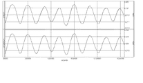
図13は通常腹式呼吸時の呼吸波形であり、図14は、閉塞型無呼吸を模擬した実験における呼吸波形である。図13及び14いずれも、上段が胸部の呼吸運動を反映した信号であり、下段が腹部の呼吸運動を反映した信号である。図13によれば、通常腹式呼吸時は、胸部の呼吸運動を反映した信号、および、腹部の呼吸運動を反映した信号が同位相になっていることが分かる。これに対し、図14によれば、閉塞型無呼吸時は、胸部の呼吸運動を反映した信号、および、腹部の呼吸運動を反映した信号が逆相に近くなっていることが分かる。つまり、閉塞型無呼吸時は、通常腹式呼吸時と比べ、位相が変化している。この位相変化は、閉塞型無呼吸時に特有のものであり、中枢型無呼吸時においても現れない特徴である(以下で説明する)。 FIG. 13 shows a respiratory waveform during normal abdominal breathing, and FIG. 14 shows a respiratory waveform in an experiment simulating obstructive apnea. 13 and 14, the upper stage is a signal reflecting the respiratory movement of the chest, and the lower stage is a signal reflecting the respiratory movement of the abdomen. As can be seen from FIG. 13, during normal abdominal breathing, the signal reflecting the respiratory motion of the chest and the signal reflecting the respiratory motion of the abdomen are in phase. On the other hand, according to FIG. 14, it can be seen that during obstructive apnea, the signal reflecting the respiratory motion of the chest and the signal reflecting the respiratory motion of the abdomen are close to opposite phases. In other words, the phase changes during obstructive apnea compared to normal abdominal breathing. This phase change is unique during obstructive apnea and is a feature that does not appear even during central apnea (described below).
次に、中枢型は、脳が呼吸を止める命令を出すことで無呼吸状態が生じるタイプである。中枢型無呼吸時と、閉塞型無呼吸時及び通常腹式呼吸時との相違点は、閉塞型無呼吸時及び通常腹式呼吸時は呼吸しようとする動作(呼吸運動)が行われるのに対し、中枢型無呼吸時は呼吸しようとする動作(呼吸運動)が行われない点である。このため、中枢型無呼吸時の胸部及び腹部の呼吸運動を反映した信号には、閉塞型無呼吸時に現れるような上記位相変化(逆相に近くなる変化)は現れない。また、閉塞型無呼吸時及び通常腹式呼吸時は、胸部及び腹部の呼吸運動を反映した信号に、呼吸運動に起因した波形変化が現れるが、中枢型無呼吸時は、胸部及び腹部の呼吸運動を反映した信号に、呼吸運動に起因した波形変化が現れないという相違点も現れる。 Next, the central type is a type in which an apnea occurs when the brain issues a command to stop breathing. The difference between central apnea, obstructive apnea, and normal abdominal breathing is that the action (breathing exercise) that tries to breathe is performed during obstructive apnea and normal abdominal breathing. On the other hand, during central apnea, the action (breathing movement) that tries to breathe is not performed. For this reason, in the signal reflecting the respiratory movements of the chest and abdomen during central apnea, the above phase change (change close to reverse phase) that appears during obstructive apnea does not appear. During obstructive apnea and normal abdominal breathing, a waveform change due to respiratory movement appears in the signal reflecting the respiratory movements of the chest and abdomen, but during central apnea, breathing of the chest and abdomen There is also a difference that the waveform reflecting the respiratory motion does not appear in the signal reflecting the motion.
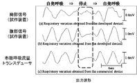
図8は中枢型無呼吸時を模擬した実験における呼吸波形である。図8に示すデータは、本実施形態の生体信号測定用ベッドと市販の呼吸トランスデューサを同時に用い、呼吸成分の信号を同時に測定したデータである。 FIG. 8 shows respiratory waveforms in an experiment simulating a central apnea. The data shown in FIG. 8 is data obtained by simultaneously measuring a respiratory component signal using the biological signal measurement bed of this embodiment and a commercially available respiratory transducer at the same time.
図中「胸部信号(試作装置)」として示すデータが、本実施形態の生体信号測定用ベッドを用い、第1の電極(胸部付近に配置)及び第3の電極(臀部付近に配置)を用いて検出した呼吸成分の信号であり、「腹部信号(試作装置)」として示すデータが、本実施形態の生体信号測定用ベッドを用い、第2の電極(腹部付近に配置)及び第3の電極(臀部付近に配置)を用いて検出した呼吸成分の信号である。また、図中「市販呼吸流量トランスデューサ」として示すデータが、市販の呼吸トランスデューサを用いて測定した呼吸成分の信号である。 Data shown as “chest signal (prototype device)” in the figure uses the biological signal measurement bed of this embodiment, and uses the first electrode (arranged near the chest) and the third electrode (arranged near the buttocks). The data of the respiratory component detected in this manner and the data shown as “abdominal signal (prototype device)” is the second electrode (arranged in the vicinity of the abdomen) and the third electrode using the biological signal measurement bed of this embodiment. It is the signal of the respiratory component detected using (arranged in the vicinity of the buttocks). In addition, data shown as “commercial respiratory flow transducer” in the figure is a respiratory component signal measured using a commercially available respiratory transducer.
図8のデータの場合、市販の呼吸トランスデューサを用いて特定された呼吸停止状態(点線部)においては、胸部信号(試作装置)及び腹部信号(試作装置)いずれにおいても、呼吸動作に起因した波形変化が現れていない。すなわち、当該呼吸停止状態(点線部)は、中枢型であることが分かる。 In the case of the data of FIG. 8, in the respiratory stop state (dotted line part) specified by using a commercially available respiratory transducer, the waveform resulting from the respiratory action in both the chest signal (prototype device) and the abdominal signal (prototype device). There is no change. That is, it can be seen that the respiratory stop state (dotted line portion) is a central type.
混合型は、閉塞型と中枢型が混合して現れるタイプである。すなわち、胸部の呼吸運動を反映した信号、及び、腹部の呼吸運動を反映した信号には、互いの信号が逆相に近くなる位相変化(閉塞型)、及び、当該位相変化が現れない呼吸停止状態を示す波形、例えば、胸部及び腹部の呼吸運動を反映した信号いずれにおいても呼吸運動に起因した波形変化が現れない状態(中枢型)が混合して現れる。 The mixed type is a type in which an occlusion type and a central type appear mixedly. That is, in the signal reflecting the respiratory motion of the chest and the signal reflecting the respiratory motion of the abdomen, the phase change where each signal is close to the opposite phase (occlusion type), and the respiratory stop where the phase change does not appear A state (central type) in which a waveform change due to respiratory motion does not appear in any of the waveforms reflecting the state, for example, signals reflecting the respiratory motion of the chest and abdomen, appears.
以上より、胸部の呼吸運動を反映した信号と、腹部の呼吸運動を反映した信号を同時に測定することができる本実施形態によれば、これらのデータを解析し、上述した閉塞型、中枢型及び混合型各々に特有の変化を検出することで、睡眠時無呼吸症候群のタイプを推定することが可能となる。 From the above, according to the present embodiment, which can simultaneously measure a signal reflecting the respiratory motion of the chest and a signal reflecting the respiratory motion of the abdomen, these data are analyzed, and the above-described obstruction type, central type and By detecting a change peculiar to each of the mixed types, it is possible to estimate the type of sleep apnea syndrome.
(4)ここで、図9に、本実施形態の生体信号測定用ベッドを用い、第1の電極(胸部付近に配置)及び第3の電極(臀部付近に配置)を用いて検出した呼吸成分の信号から算出した分時呼吸数と、市販の呼吸トランスデューサを用いて同時に測定した呼吸成分の信号から算出した分時呼吸数との相関関係を示す。(a)は仰臥位の被験者から測定した結果であり、相関関数は0.821である。(b)は側臥位の被験者から測定した結果であり、相関関数は0.910である。(c)は腹臥位の被験者から測定した結果であり、相関関数は0.994である。いずれも十分な測定精度を示しているが、特に、腹臥位の被験者から測定した場合に、最もよい測定精度が得られることが分かる。 (4) Here, in FIG. 9, using the biological signal measurement bed of the present embodiment, the respiratory component detected using the first electrode (arranged near the chest) and the third electrode (arranged near the buttocks) 3 shows the correlation between the minute respiratory rate calculated from the above signal and the minute respiratory rate calculated from the respiratory component signal measured simultaneously using a commercially available respiratory transducer. (A) is the result measured from the supine subject, and the correlation function is 0.821. (B) is the result measured from the subject in the lateral position, and the correlation function is 0.910. (C) is the result measured from the prone position subject, and the correlation function is 0.994. Although all show sufficient measurement accuracy, it turns out that the best measurement accuracy is obtained especially when it measures from the test subject of prone position.
次に、図10に、本実施形態の生体信号測定用ベッドを用い、第2の電極(腹部付近に配置)及び第3の電極(臀部付近に配置)を用いて検出した呼吸成分の信号から算出した分時呼吸数と、市販の呼吸トランスデューサを用いて同時に測定した呼吸成分の信号から算出した分時呼吸数との相関関係を示す。(a)は仰臥位の被験者から測定した結果であり、相関関数は0.991である。(b)は側臥位の被験者から測定した結果であり、相関関数は0.318である。(c)は腹臥位の被験者から測定した結果であり相関関数は−0.057である。仰臥位の被験者から測定した場合、十分な測定精度を示しているが、側臥位及び腹臥位の被験者から測定した場合の測定精度は不十分であった。 Next, in FIG. 10, from the signal of the respiratory component detected using the second electrode (arranged near the abdomen) and the third electrode (arranged near the buttocks) using the biological signal measurement bed of this embodiment. The correlation between the calculated minute respiratory rate and the minute respiratory rate calculated from the signal of the respiratory component measured simultaneously using a commercially available respiratory transducer is shown. (A) is the result measured from the subject in the supine position, and the correlation function is 0.991. (B) is the result measured from the subject in the lateral position, and the correlation function is 0.318. (C) is the result measured from the prone subject, and the correlation function is -0.057. When measured from a supine subject, sufficient measurement accuracy was shown, but when measured from a lateral and prone subject, the measurement accuracy was insufficient.
(5)次に、図11に、睡眠状態の被験者から、本実施形態の生体信号測定用ベッドと市販の装置を同時に用い、心電図成分の信号と呼吸成分の信号を同時に測定したデータを示す。 (5) Next, FIG. 11 shows data obtained by simultaneously measuring a signal of an electrocardiogram component and a signal of a respiratory component from a sleeping subject using the biological signal measurement bed of this embodiment and a commercially available device at the same time.
データの示し方は図7と同様であるが、さらに、市販の装置を用いて同時に測定した脈波の信号を「(g)脈波:市販装置」として示している。当該データより、睡眠状態の被験者から測定した場合であっても、図7を用いて説明した結果と同様の結果が得られることが分かる。 The way of displaying the data is the same as in FIG. 7, but the pulse wave signal simultaneously measured using a commercially available device is shown as “(g) Pulse wave: Commercial device”. From the data, it can be seen that the same result as that described with reference to FIG. 7 can be obtained even when measured from a sleeping subject.
次に、図12に、睡眠状態の被験者から、本実施形態の生体信号測定用ベッドを用いて測定した場合のR波の検出率の経時変化を示す。図に示すように、R波検出率は平均99.4%であり、高い確率で心電を計測できることが分かる。 Next, FIG. 12 shows the change over time in the detection rate of the R wave when measured from a sleeping subject using the biological signal measurement bed of the present embodiment. As shown in the figure, the R wave detection rate is 99.4% on average, and it can be seen that the electrocardiogram can be measured with high probability.
(6)睡眠時無呼吸症候群罹患者は、日本国内に300万人程いると推計されているが、検査施設や機会が限られているため通院して治療を受けている患者数は6万人程度(約2%)といわれている。当該症状をそのまま放置すると、日常生活に支障をきたして交通事故の発症率が高くなるほか、高血圧や心臓血管疾患病の発症率が上昇する。本実施形態の生体信号測定用ベッド及び生体信号測定装置によれば、家庭内等で簡易に睡眠時無呼吸症候群罹患者のスクリーニングを行うことが可能となる。そして、病気の早期発見や、医療費削減などの優れた効果を実現することができる。 (6) Although it is estimated that there are about 3 million people with sleep apnea syndrome in Japan, there are 60,000 patients who are hospitalized and treated due to limited testing facilities and opportunities. It is said that the number of people is about 2%. If this condition is left as it is, it will interfere with daily life and increase the incidence of traffic accidents, and also increase the incidence of hypertension and cardiovascular disease. According to the biological signal measuring bed and the biological signal measuring device of this embodiment, it becomes possible to easily screen a person suffering from sleep apnea syndrome at home or the like. In addition, it is possible to realize excellent effects such as early detection of diseases and reduction of medical expenses.
以上、本実施形態の生体信号測定用ベッド及び生体信号測定装置について説明したが、上記説明によれば、本実施形態の生体信号測定用ベッドを利用した生体信号測定方法であって、本実施形態のマットレス24にシーツを被せ、第1乃至第3の電極11乃至13を当該シーツで覆った状態で、その上に被験者が横になり、生体信号を測定する生体信号測定方法の説明もなされている。
The biological signal measurement bed and the biological signal measurement device according to the present embodiment have been described above. According to the above description, the biological signal measurement method using the biological signal measurement bed according to the present embodiment is described. A biological signal measuring method for measuring a biological signal is described in which a subject lies on the
また、本実施形態は以下のような変形例とすることもできる。 Further, the present embodiment may be modified as follows.
すなわち、上記例では、マットレス24の上に第1乃至第3の電極11乃至13が位置したが、敷布団などその他の物の上に第1乃至第3の電極11乃至13を位置させることも可能である。
That is, in the above example, the first to
また、上記例では、(1)マットレス24の上に露出するように第1乃至第3の電極11乃至13を配置し、(2)当該第1乃至第3の電極11乃至13をシーツ(絶縁物)で覆い、(3)当該シーツの上に被験者が横になることで、図5を用いて説明した「結合部」を実現したが、その他の例とすることもできる。例えば、マットレス24の外側表面を構成する絶縁性被覆(例:布地、ビニル素材等)の裏地に第1乃至第3の電極11乃至13を取り付け(例:貼付)てもよい。かかる場合、被験者がマットレス24の当該絶縁性被覆の上に直接横になることで、「結合部」を実現することができ、測定が可能となる。なお、絶縁性被覆は、結合部の絶縁物として機能できる薄さにする必要がある。
Further, in the above example, (1) the first to
また、上記例では、マットレス24の上に第1乃至第3の電極11乃至13を配置し、その上に被験者が横になって測定する例を説明したが、第1乃至第3の電極11乃至13をマットレス24の上に配置するのでなく、被験者の胸部(または胸背部)、腹部(または腹背部)及び臀部に直接、衣服を介して装着することも可能である。
In the above example, the first to
また、上記例では、容量性結合の原理を応用し、第1乃至第3の電極11乃至13と、被験者の皮膚との間に絶縁物を介して測定する例を説明したが、被験者の皮膚に第1乃至第3の電極11乃至13を直接貼付して測定する例においても、同様の作用効果を実現できる。
In the above example, the principle of capacitive coupling is applied, and an example in which measurement is performed through an insulator between the first to
11 第1の電極
12 第2の電極
13 第3の電極
14 第1の分離回路
15 第2の分離回路
16 グランド
17 バッファ
18 バッファ
19 バッファ
20 コンデンサ
21 コンデンサ
22 コンデンサ
23 コンデンサ及びグランド
24 マットレス
DESCRIPTION OF
Claims (12)
前記第1乃至第3の電極各々とコンデンサ又は抵抗を介して繋がったグランドと、
前記第1の電極からの信号及び前記第3の電極からの信号各々が、バッファを介して入力されるとともに、前記グランドが回路のグランドとして接続される第1の分離回路と、
前記第2の電極からの信号及び前記第3の電極からの信号各々が、バッファを介して入力されるとともに、前記グランドが回路のグランドとして接続される第2の分離回路と、
を有し、
前記第1及び第2の分離回路は、入力された信号を、呼吸成分と心電図成分に分離する分離フィルタを有する生体信号測定装置。 First to third electrodes;
A ground connected to each of the first to third electrodes via a capacitor or a resistor;
A first separation circuit in which a signal from the first electrode and a signal from the third electrode are each input via a buffer, and the ground is connected as a circuit ground;
A second separation circuit in which a signal from the second electrode and a signal from the third electrode are each input via a buffer, and the ground is connected as a circuit ground;
Have
The said 1st and 2nd separation circuit is a biological signal measuring device which has a separation filter which isolate | separates the input signal into a respiration component and an electrocardiogram component.
前記第1乃至第3の電極各々とコンデンサ又は抵抗を介して繋がったグランドと、
前記第1の電極からの信号及び前記第3の電極からの信号各々が、バッファを介して入力されるとともに、前記グランドが回路のグランドとして接続される第1の分離回路と、
前記第2の電極からの信号及び前記第3の電極からの信号各々が、バッファを介して入力されるとともに、前記グランドが回路のグランドとして接続される第2の分離回路と、
を有し、
前記第1及び第2の分離回路は、入力された信号を、第1の周波数帯と第2の周波数帯に分離する分離フィルタを有する生体信号測定装置。 First to third electrodes;
A ground connected to each of the first to third electrodes via a capacitor or a resistor;
A first separation circuit in which a signal from the first electrode and a signal from the third electrode are each input via a buffer, and the ground is connected as a circuit ground;
A second separation circuit in which a signal from the second electrode and a signal from the third electrode are each input via a buffer, and the ground is connected as a circuit ground;
Have
The said 1st and 2nd separation circuit is a biological signal measuring apparatus which has a separation filter which isolate | separates the input signal into the 1st frequency band and the 2nd frequency band.
前記第1の周波数帯は1Hz以上10Hz以下の間の所定値以上の周波数帯であり、前記第2の周波数帯は前記所定値未満の周波数帯である生体信号測定装置。 The biological signal measuring apparatus according to claim 2,
The biological signal measuring device, wherein the first frequency band is a frequency band greater than or equal to a predetermined value between 1 Hz and 10 Hz, and the second frequency band is a frequency band less than the predetermined value.
前記第1の電極は胸部の信号を検知し、前記第2の電極は腹部の信号を検知し、前記第3の電極は臀部の信号を検知する生体信号測定装置。 The biological signal measuring apparatus according to any one of claims 1 to 3,
The biological signal measuring device in which the first electrode detects a chest signal, the second electrode detects an abdominal signal, and the third electrode detects a buttocks signal.
生体信号測定時、前記第1乃至第3の電極は絶縁物を介して人体と接触する生体信号測定装置。 In the biological signal measuring device according to any one of claims 1 to 4,
The biological signal measuring device in which the first to third electrodes are in contact with a human body via an insulator during measurement of a biological signal.
前記第1乃至第3の電極が備えられたマットレスを有する生体信号測定用ベッド。 The biological signal measurement bed according to claim 6,
A biological signal measuring bed having a mattress provided with the first to third electrodes.
前記第1の電極、前記第2の電極、及び、前記第3の電極はこの順に配置されている生体信号測定用ベッド。 The biological signal measurement bed according to claim 7,
The biological signal measurement bed in which the first electrode, the second electrode, and the third electrode are arranged in this order.
前記第1乃至第3の電極は、マットレスの表面において露出している生体信号測定用ベッド。 In the establishment signal measurement bed according to claim 7 or 8,
The first to third electrodes are biological signal measurement beds exposed on the surface of the mattress.
前記第1乃至第3の電極は、マットレスの外側表面を構成する絶縁性被覆の裏地に取り付けられている生体信号測定用ベッド。 In the establishment signal measurement bed according to claim 7 or 8,
The said 1st thru | or 3rd electrode is a bed for a biosignal measurement attached to the lining of the insulating coating | cover which comprises the outer surface of a mattress.
前記マットレスにシーツを被せ、前記第1乃至第3の電極を前記シーツで覆った状態で、その上に被験者が横になり、生体信号を測定する生体信号測定方法。 A biological signal measurement method using the biological signal measurement bed according to claim 9,
A biological signal measuring method for measuring a biological signal by placing a sheet on the mattress and covering the first to third electrodes with the sheet and a subject lying on the sheet.
被験者が前記マットレスの前記絶縁性被覆の上に直接横になり、生体信号を測定する生体信号測定方法。 A biological signal measurement method using the biological signal measurement bed according to claim 10,
A biological signal measuring method in which a subject lies directly on the insulating coating of the mattress and measures a biological signal.
Priority Applications (1)
| Application Number | Priority Date | Filing Date | Title |
|---|---|---|---|
| JP2011073940A JP5820600B2 (en) | 2011-03-30 | 2011-03-30 | Biological signal measuring device, biological signal measuring bed, and biological signal measuring method |
Applications Claiming Priority (1)
| Application Number | Priority Date | Filing Date | Title |
|---|---|---|---|
| JP2011073940A JP5820600B2 (en) | 2011-03-30 | 2011-03-30 | Biological signal measuring device, biological signal measuring bed, and biological signal measuring method |
Publications (2)
| Publication Number | Publication Date |
|---|---|
| JP2012205784A true JP2012205784A (en) | 2012-10-25 |
| JP5820600B2 JP5820600B2 (en) | 2015-11-24 |
Family
ID=47186116
Family Applications (1)
| Application Number | Title | Priority Date | Filing Date |
|---|---|---|---|
| JP2011073940A Expired - Fee Related JP5820600B2 (en) | 2011-03-30 | 2011-03-30 | Biological signal measuring device, biological signal measuring bed, and biological signal measuring method |
Country Status (1)
| Country | Link |
|---|---|
| JP (1) | JP5820600B2 (en) |
Cited By (5)
| Publication number | Priority date | Publication date | Assignee | Title |
|---|---|---|---|---|
| JP2015181841A (en) * | 2014-03-25 | 2015-10-22 | フクダ電子株式会社 | Biological signal processing device and control method thereof |
| JP2017192825A (en) * | 2013-05-13 | 2017-10-26 | ヘルスセンシング株式会社 | Human health condition detecting device |
| WO2018030393A1 (en) * | 2016-08-12 | 2018-02-15 | 学校法人東京電機大学 | Vital sign measurement sheet and vital sign measurement device |
| JP2019037659A (en) * | 2017-08-28 | 2019-03-14 | 学校法人東京電機大学 | Measuring apparatus, measuring method, and program |
| WO2021090955A1 (en) * | 2019-11-08 | 2021-05-14 | 株式会社エクォス・リサーチ | Biosignal detection device, heart rate signal detection server, vehicle, biosignal detection program, and heart rate signal detection program |
Citations (10)
| Publication number | Priority date | Publication date | Assignee | Title |
|---|---|---|---|---|
| JPH0217111U (en) * | 1988-07-21 | 1990-02-05 | ||
| JP2002136502A (en) * | 2000-09-25 | 2002-05-14 | Siemens Ag | Physiological sensor system |
| JP2003530184A (en) * | 2000-04-17 | 2003-10-14 | ビボメトリックス,インコーポレイテッド | Monitoring device, system, and recording medium for wearing physiologically monitor physiological signs |
| JP2005509464A (en) * | 2001-07-03 | 2005-04-14 | インストルメンタリウム コーポレイション | Configurable sensor system for measuring biopotentials |
| JP2005143661A (en) * | 2003-11-12 | 2005-06-09 | Toshiba Corp | Bed for image diagnostic device |
| JP2005342216A (en) * | 2004-06-03 | 2005-12-15 | Yamatake Corp | Ah measuring device |
| JP2008099957A (en) * | 2006-10-20 | 2008-05-01 | Showa Denko Kk | Sheet for measuring biometric information |
| WO2008090862A1 (en) * | 2007-01-23 | 2008-07-31 | Tohoku Techno Arch Co., Ltd. | Fetus electrocardiogram signal measuring method and its device |
| JP2010194137A (en) * | 2009-02-26 | 2010-09-09 | Ritsumeikan | Noncontact electrocardiographic sensor |
| JP2010284498A (en) * | 2009-05-12 | 2010-12-24 | Tokuo Saito | Device for collecting and transmitting biological information |
-
2011
- 2011-03-30 JP JP2011073940A patent/JP5820600B2/en not_active Expired - Fee Related
Patent Citations (10)
| Publication number | Priority date | Publication date | Assignee | Title |
|---|---|---|---|---|
| JPH0217111U (en) * | 1988-07-21 | 1990-02-05 | ||
| JP2003530184A (en) * | 2000-04-17 | 2003-10-14 | ビボメトリックス,インコーポレイテッド | Monitoring device, system, and recording medium for wearing physiologically monitor physiological signs |
| JP2002136502A (en) * | 2000-09-25 | 2002-05-14 | Siemens Ag | Physiological sensor system |
| JP2005509464A (en) * | 2001-07-03 | 2005-04-14 | インストルメンタリウム コーポレイション | Configurable sensor system for measuring biopotentials |
| JP2005143661A (en) * | 2003-11-12 | 2005-06-09 | Toshiba Corp | Bed for image diagnostic device |
| JP2005342216A (en) * | 2004-06-03 | 2005-12-15 | Yamatake Corp | Ah measuring device |
| JP2008099957A (en) * | 2006-10-20 | 2008-05-01 | Showa Denko Kk | Sheet for measuring biometric information |
| WO2008090862A1 (en) * | 2007-01-23 | 2008-07-31 | Tohoku Techno Arch Co., Ltd. | Fetus electrocardiogram signal measuring method and its device |
| JP2010194137A (en) * | 2009-02-26 | 2010-09-09 | Ritsumeikan | Noncontact electrocardiographic sensor |
| JP2010284498A (en) * | 2009-05-12 | 2010-12-24 | Tokuo Saito | Device for collecting and transmitting biological information |
Non-Patent Citations (1)
| Title |
|---|
| JPN7014003433; 山芳寛: '容量型シートセンサを用いた乳児の狭帯域心電図および呼吸情報の簡易的無拘束計測' 生体医工学 vol.47, no.1, 2009, p.42-50 * |
Cited By (9)
| Publication number | Priority date | Publication date | Assignee | Title |
|---|---|---|---|---|
| JP2017192825A (en) * | 2013-05-13 | 2017-10-26 | ヘルスセンシング株式会社 | Human health condition detecting device |
| JP2015181841A (en) * | 2014-03-25 | 2015-10-22 | フクダ電子株式会社 | Biological signal processing device and control method thereof |
| WO2018030393A1 (en) * | 2016-08-12 | 2018-02-15 | 学校法人東京電機大学 | Vital sign measurement sheet and vital sign measurement device |
| JPWO2018030393A1 (en) * | 2016-08-12 | 2019-06-13 | 学校法人東京電機大学 | Biological information measuring sheet and biological information measuring device |
| JP2019037659A (en) * | 2017-08-28 | 2019-03-14 | 学校法人東京電機大学 | Measuring apparatus, measuring method, and program |
| JP6989942B2 (en) | 2017-08-28 | 2022-01-12 | 学校法人東京電機大学 | Measuring equipment, measuring methods and programs |
| WO2021090955A1 (en) * | 2019-11-08 | 2021-05-14 | 株式会社エクォス・リサーチ | Biosignal detection device, heart rate signal detection server, vehicle, biosignal detection program, and heart rate signal detection program |
| JP2021074272A (en) * | 2019-11-08 | 2021-05-20 | 株式会社エクォス・リサーチ | Biological signal detection device, heart rate signal detection server, vehicle, biological signal detection program, and heart rate signal detection program |
| JP7169589B2 (en) | 2019-11-08 | 2022-11-11 | 株式会社アイシン | Biosignal detection device, heartbeat signal detection server, vehicle, biosignal detection program, and heartbeat signal detection program |
Also Published As
| Publication number | Publication date |
|---|---|
| JP5820600B2 (en) | 2015-11-24 |
Similar Documents
| Publication | Publication Date | Title |
|---|---|---|
| Pandia et al. | Extracting respiratory information from seismocardiogram signals acquired on the chest using a miniature accelerometer | |
| Droitcour et al. | Non-contact respiratory rate measurement validation for hospitalized patients | |
| Hung et al. | Estimation of respiratory waveform using an accelerometer | |
| JP6599723B2 (en) | Biological information acquisition apparatus and signal processing method | |
| KR20180108664A (en) | A sleep state measuring apparatus and method, a phase coherence calculating apparatus, a living body vibration signal measuring apparatus, a stress state measuring apparatus and a sleep state measuring apparatus, and a heartbeat waveform extracting method | |
| Takano et al. | Noncontact in-bed measurements of physiological and behavioral signals using an integrated fabric-sheet sensing scheme | |
| Haescher et al. | SeismoTracker: Upgrade any smart wearable to enable a sensing of heart rate, respiration rate, and microvibrations | |
| JP5820600B2 (en) | Biological signal measuring device, biological signal measuring bed, and biological signal measuring method | |
| CN104545888B (en) | A kind of sleep apnea acquisition analysis system based on dynamic electrocardiogram and respiratory wave acquisition | |
| JP6883341B2 (en) | Biometric information measurement sheet and biometric information measuring device | |
| WO2018130036A1 (en) | Multi-sensor cardiopulmonary coupling sleep quality detection system and detection method thereof | |
| KR20180018581A (en) | Wearable technologies for joint health assessment | |
| JP4637963B1 (en) | HRV change detection method for health judgment and HRV change detection device for health judgment | |
| CN105997088A (en) | Sleep breath detection device based on flexible force sensor | |
| CN105997085B (en) | Wearable dynamic monitoring pectoral girdle for chronic obstructive pulmonary disease | |
| Młyńczak et al. | Impedance pneumography: Is it possible? | |
| CN102697488B (en) | Unrestrained sleep physiological information detection device | |
| Yang et al. | Pneumatic sensor for cardiorespiratory monitoring during sleep | |
| CN104274173A (en) | Bio-impedance-based wearable sleep respiration state monitoring system | |
| CN105640524A (en) | Device for monitoring breath and heartbeat during sleeping | |
| Sel et al. | Measurement of chest physiological signals using wirelessly coupled bio-impedance patches | |
| US20210298683A1 (en) | Bed-based ballistocardiogram apparatus and method | |
| Saran et al. | Validation of dozee, a ballistocardiography-based device, for contactless and continuous heart rate and respiratory rate measurement | |
| WO2007094464A1 (en) | Cardiopulmonary function measuring instrument | |
| Ueno et al. | Unconstrained monitoring of ECG and respiratory variation in infants with underwear during sleep using a bed-sheet electrode unit |
Legal Events
| Date | Code | Title | Description |
|---|---|---|---|
| A621 | Written request for application examination |
Free format text: JAPANESE INTERMEDIATE CODE: A621 Effective date: 20140314 |
|
| A977 | Report on retrieval |
Free format text: JAPANESE INTERMEDIATE CODE: A971007 Effective date: 20141113 |
|
| A131 | Notification of reasons for refusal |
Free format text: JAPANESE INTERMEDIATE CODE: A131 Effective date: 20141202 |
|
| A521 | Request for written amendment filed |
Free format text: JAPANESE INTERMEDIATE CODE: A523 Effective date: 20141222 |
|
| A02 | Decision of refusal |
Free format text: JAPANESE INTERMEDIATE CODE: A02 Effective date: 20150512 |
|
| RD01 | Notification of change of attorney |
Free format text: JAPANESE INTERMEDIATE CODE: A7426 Effective date: 20150610 |
|
| A521 | Request for written amendment filed |
Free format text: JAPANESE INTERMEDIATE CODE: A821 Effective date: 20150610 |
|
| A521 | Request for written amendment filed |
Free format text: JAPANESE INTERMEDIATE CODE: A523 Effective date: 20150807 |
|
| A911 | Transfer to examiner for re-examination before appeal (zenchi) |
Free format text: JAPANESE INTERMEDIATE CODE: A911 Effective date: 20150819 |
|
| TRDD | Decision of grant or rejection written | ||
| A01 | Written decision to grant a patent or to grant a registration (utility model) |
Free format text: JAPANESE INTERMEDIATE CODE: A01 Effective date: 20150929 |
|
| A61 | First payment of annual fees (during grant procedure) |
Free format text: JAPANESE INTERMEDIATE CODE: A61 Effective date: 20151005 |
|
| R150 | Certificate of patent or registration of utility model |
Ref document number: 5820600 Country of ref document: JP Free format text: JAPANESE INTERMEDIATE CODE: R150 |
|
| R250 | Receipt of annual fees |
Free format text: JAPANESE INTERMEDIATE CODE: R250 |
|
| R250 | Receipt of annual fees |
Free format text: JAPANESE INTERMEDIATE CODE: R250 |
|
| R250 | Receipt of annual fees |
Free format text: JAPANESE INTERMEDIATE CODE: R250 |
|
| R250 | Receipt of annual fees |
Free format text: JAPANESE INTERMEDIATE CODE: R250 |
|
| LAPS | Cancellation because of no payment of annual fees |