JP2012205379A - Charging system, power supply device, mobile body, wireless power transmission and reception system, and power reception device - Google Patents
Charging system, power supply device, mobile body, wireless power transmission and reception system, and power reception device Download PDFInfo
- Publication number
- JP2012205379A JP2012205379A JP2011067085A JP2011067085A JP2012205379A JP 2012205379 A JP2012205379 A JP 2012205379A JP 2011067085 A JP2011067085 A JP 2011067085A JP 2011067085 A JP2011067085 A JP 2011067085A JP 2012205379 A JP2012205379 A JP 2012205379A
- Authority
- JP
- Japan
- Prior art keywords
- power
- coil
- power receiving
- receiving coil
- charging
- Prior art date
- Legal status (The legal status is an assumption and is not a legal conclusion. Google has not performed a legal analysis and makes no representation as to the accuracy of the status listed.)
- Withdrawn
Links
Images

Classifications
-
- Y—GENERAL TAGGING OF NEW TECHNOLOGICAL DEVELOPMENTS; GENERAL TAGGING OF CROSS-SECTIONAL TECHNOLOGIES SPANNING OVER SEVERAL SECTIONS OF THE IPC; TECHNICAL SUBJECTS COVERED BY FORMER USPC CROSS-REFERENCE ART COLLECTIONS [XRACs] AND DIGESTS
- Y02—TECHNOLOGIES OR APPLICATIONS FOR MITIGATION OR ADAPTATION AGAINST CLIMATE CHANGE
- Y02T—CLIMATE CHANGE MITIGATION TECHNOLOGIES RELATED TO TRANSPORTATION
- Y02T10/00—Road transport of goods or passengers
- Y02T10/60—Other road transportation technologies with climate change mitigation effect
- Y02T10/72—Electric energy management in electromobility
Abstract
Description
本発明は、無線で電力伝送を行なう充電システム、それを用いた電源装置、移動体、無線電力送受電システム及びそこで用いられる受電装置に関する。 The present invention relates to a charging system that wirelessly transmits power, a power supply device using the charging system, a mobile unit, a wireless power transmission / reception system, and a power receiving device used therein.
近年、電力伝送用の線路を使用しない所謂無線による電力伝送(以下、無線電力伝送)の方式が注目されてきている。この無線電力伝送方式としては、電磁誘導型、電波受信型、および共鳴型の3方式が主に知られている。 In recent years, a so-called wireless power transmission method (hereinafter referred to as wireless power transmission) that does not use a power transmission line has attracted attention. As this wireless power transmission system, three systems of an electromagnetic induction type, a radio wave reception type, and a resonance type are mainly known.
電磁誘導型は、所謂電磁誘導現象を利用する事により、送電側の1次コイルから受電側の2次コイルへ向けて伝送された磁場の変化によって送電側から受電側に電力を伝送(送電)する方式である。電波受信型は、アンテナで受信した電波信号を検波回路により直流に検波して直流電力を得る方式である。共鳴型は、電場または磁場の少なくとも一方における共鳴現象を利用して電力を伝送する方式である。 The electromagnetic induction type uses a so-called electromagnetic induction phenomenon to transmit power from the power transmission side to the power reception side due to a change in the magnetic field transmitted from the power transmission side primary coil to the power reception side secondary coil (power transmission). It is a method to do. The radio wave reception type is a system in which a radio wave signal received by an antenna is detected to a direct current by a detection circuit to obtain direct current power. The resonance type is a method of transmitting electric power using a resonance phenomenon in at least one of an electric field or a magnetic field.
磁場における共鳴現象を利用した磁気共鳴方式では、発振器で発振した発振波を送電側の1次結合コイルから電磁誘導により送電側の1次共振コイルへ無線で電力伝送し、この送電側1次共振コイルと受電側の2次共振コイルの間において磁気共鳴現象によって無線電力伝送を行なう。なお、2次側(受電側)も共振コイルと結合コイルから構成され、2次共振コイルと受電側の2次結合コイルの間では電磁誘導により電力伝送がなされ、受電した発信波を整流することによって送電側から受電側に無線電力伝送がなされる。 In the magnetic resonance method using the resonance phenomenon in the magnetic field, the oscillation wave oscillated by the oscillator is wirelessly transmitted from the primary coupling coil on the power transmission side to the primary resonance coil on the power transmission side by electromagnetic induction, and this power transmission side primary resonance is transmitted. Wireless power transmission is performed by a magnetic resonance phenomenon between the coil and the secondary resonance coil on the power receiving side. The secondary side (power receiving side) is also composed of a resonance coil and a coupling coil, and power is transmitted between the secondary resonance coil and the power receiving side secondary coupling coil by electromagnetic induction to rectify the received transmitted wave. Thus, wireless power transmission is performed from the power transmission side to the power reception side.
磁気共鳴方式の電力伝送を行なう給電装置としては、例えば下記特許文献1のような技術が開示されている。この技術では1つの2次自己共振コイル(上述の2次共振コイル)に対して平面方向に配された複数の2次コイル(上述の2次結合コイル)を備えるものである。ここでは、受電しようとしていた1つの2次コイルから漏れた分を他の2次コイルで受電することを目的としている。なお、複数の2次コイルは一つの整流器に接続されており、受電した発振信号は当該整流器に集中する。 As a power supply device that performs magnetic resonance type power transmission, for example, a technique disclosed in Patent Document 1 below is disclosed. This technology includes a plurality of secondary coils (the above-described secondary coupling coils) arranged in a plane direction with respect to one secondary self-resonant coil (the above-described secondary resonance coil). Here, the purpose is to receive the power leaked from one secondary coil that was going to receive power with another secondary coil. A plurality of secondary coils are connected to one rectifier, and the received oscillation signal is concentrated on the rectifier.
無線電力伝送では、送信側から発信信号を送出させて受信側で発振信号を受信して検波または整流(以下では、区別せずにまとめて整流とよぶ)するので、検波回路又は整流回路(以下では、区別せずにまとめて整流回路と呼ぶ)には半導体素子などの整流素子が使用される。この整流素子は、伝送される電力が大きくなるほど、以下のような問題点が重みをましてくる。まず、伝送される電力が大きくなると整流素子のサイズが大きくなり、サイズが大きくなるに連れて、整流素子における寄生容量成分(半導体pn接合部の接合容量や、いわゆる線間容量などからなる)が増加する。この寄生容量成分があるために、本来整流素子を流れるべき高周波電力の一部がグランドにバイパスされてしまい、伝送すべき電力にロスが生じる。よって、伝送する電力が大電力となるに連れて高周波領域における整流効率が低下し、電力伝送の効率が低下する。磁気共鳴方式では数MHz〜数十MHzの発振周波数が使用され、百数十kHz以下の発振周波数が一般に使用される電磁誘導型に比べて周波数が高く、高周波領域における電力伝送特性(以下、高周波特性とも呼ぶ)が重要となってくる。また整流素子には、いわゆる順方向電圧(PN接合部の空乏層がキャリアの移動を妨げることに抗し、キャリア移動のために順方向に印加する電圧のこと)が必要となり、大電力用の整流素子ではこの順方向電圧が大きくなる。整流素子から出力される電圧が低くなると相対的に出力電圧に対する順方向電圧の割合が大きくなり、結果として整流効率が低下し、電力伝送の効率が低下する。 In wireless power transmission, a transmission signal is transmitted from the transmission side, and an oscillation signal is received on the reception side to detect or rectify (hereinafter referred to collectively as rectification without distinction). In this case, a rectifier such as a semiconductor element is used for the rectifier circuit. In this rectifying element, the following problems are weighted as the transmitted power increases. First, as the transmitted power increases, the size of the rectifying element increases. As the size increases, parasitic capacitance components in the rectifying element (consisting of a junction capacitance of a semiconductor pn junction, a so-called line capacitance, etc.) are generated. To increase. Because of this parasitic capacitance component, a part of the high-frequency power that should originally flow through the rectifying element is bypassed to the ground, and a loss occurs in the power to be transmitted. Therefore, as the power to be transmitted increases, the rectification efficiency in the high frequency region decreases, and the power transmission efficiency decreases. In the magnetic resonance method, an oscillation frequency of several MHz to several tens of MHz is used, and an oscillation frequency of hundreds of tens of kHz or less is higher than an electromagnetic induction type that is generally used. Is also important). In addition, the rectifier element requires a so-called forward voltage (a voltage applied in the forward direction for carrier movement against the depletion layer of the PN junction preventing the carrier movement) In the rectifying element, the forward voltage is increased. When the voltage output from the rectifying element is lowered, the ratio of the forward voltage to the output voltage is relatively increased. As a result, the rectification efficiency is lowered and the power transmission efficiency is lowered.
しかしながら上述の特許文献における技術では、伝送電力が大電力となった場合のこうした整流効率の低下を解決することはできない。また当該特許文献における技術では、平面方向に複数の2次コイルが配されているので、受電装置のサイズが大きくなる問題点もある。 However, the technique in the above-mentioned patent document cannot solve such a decrease in rectification efficiency when the transmission power becomes large. Further, in the technique in the patent document, since a plurality of secondary coils are arranged in the planar direction, there is a problem that the size of the power receiving device is increased.
上記問題点を鑑み、本発明は無線電力伝送方式における受電装置において電力の伝送効率を改善させた、充電システム、電源装置、移動体、無線電力送受電システム及び受電装置を提供する事を目的とする。 In view of the above problems, an object of the present invention is to provide a charging system, a power supply device, a mobile unit, a wireless power transmission / reception system, and a power receiving device that improve power transmission efficiency in a power receiving device in a wireless power transmission method. To do.
加えて、受電装置のサイズ増加を低減させた充電システム、電源装置、移動体、無線電力送受電システム及び受電装置を提供する事を目的とする。 In addition, an object is to provide a charging system, a power supply device, a mobile unit, a wireless power transmission / reception system, and a power receiving device in which an increase in the size of the power receiving device is reduced.
本発明に係る充電システムは、送電装置から無線で送電された電力を受電する受電装置と、蓄電装置と、前記受電装置が受電した電力を前記蓄電装置に充電する充電回路とを備え、前記受電装置は、前記電力を受電する第1の受電コイルと、第2の受電コイルとを有し、前記第1の受電コイルには第1の整流回路が接続され、かつ、前記第2の受電コイルは第2の整流回路が接続され、前記第1の受電コイルと前記第2の受電コイルは、前記第1の受電コイルが接する面と前記第2の受電コイルが接する面が異なり、かつ、前記第1の受電コイルを貫く磁束の全て又は一部が前記第2の受電コイルを貫くような位置関係で配置されており、前記充電回路は、前記第1の整流回路および前記第2の整流回路を通じて、前記第1の受電コイルおよび前記第2の受電コイルが受電した電力を前記蓄電装置に出力する事で、前記受電装置が受電した電力を前記蓄電装置に充電する。 A charging system according to the present invention includes: a power receiving device that receives power transmitted wirelessly from a power transmitting device; a power storage device; and a charging circuit that charges the power storage device with power received by the power receiving device. The apparatus includes a first power receiving coil that receives the power, and a second power receiving coil, a first rectifier circuit is connected to the first power receiving coil, and the second power receiving coil Is connected to a second rectifier circuit, and the first power receiving coil and the second power receiving coil are different in a surface in contact with the first power receiving coil and a surface in contact with the second power receiving coil, and All or part of the magnetic flux passing through the first power receiving coil is disposed in a positional relationship so as to pass through the second power receiving coil, and the charging circuit includes the first rectifier circuit and the second rectifier circuit. Through the first power receiving coil and By delivering power to the second power-receiving coil is powered to the power storage device to charge the power the power receiving device is powered on the electrical storage device.
このように、第1の受電コイルを貫く磁束の全て又は一部が第2の受電コイルを貫くような位置関係で第1の受電コイルと第2の受電コイルを備え、各受電コイル毎に整流回路を有し、前記第1の受電コイルおよび前記第2の受電コイルが受電した電力を前記蓄電装置に出力する構成により、無線電力伝送方式における受電装置において電力の伝送効率を改善させた、充電システムを提供することができる。加えて、受電装置のサイズ増加を低減させた充電システムを提供することができる。 As described above, the first power receiving coil and the second power receiving coil are provided in such a positional relationship that all or part of the magnetic flux passing through the first power receiving coil passes through the second power receiving coil, and rectification is performed for each power receiving coil. Charging having improved power transmission efficiency in a power receiving device in a wireless power transmission system by having a circuit and outputting the power received by the first power receiving coil and the second power receiving coil to the power storage device A system can be provided. In addition, a charging system in which an increase in the size of the power receiving device is reduced can be provided.
なお、前記受電装置は基板を有し、前記第1の受電コイルと前記第2の受電コイルが前記基板の両面に存在してもよい。 Note that the power receiving device may include a substrate, and the first power receiving coil and the second power receiving coil may exist on both surfaces of the substrate.
なお、前記第1の受電コイルが接する面における前記第1の受電コイルが描く形状の面積と前記第2の受電コイルが接する面における前記第2の受電コイルが描く形状の面積とが異なってもよい。 Note that even if the area of the shape drawn by the first power receiving coil on the surface in contact with the first power receiving coil is different from the area of the shape drawn by the second power receiving coil on the surface in contact with the second power receiving coil. Good.
また、前記送電装置は前記受電装置の前記第1の受電コイルまたは前記第2の受電コイルへ向けて無線で電力を送電する送電コイルを有し、前記送電コイルの中心と前記第1の受電コイルの中心との間の距離、または前記送電コイルの中心と前記第2の受電コイルの中心との間の距離である伝送距離を検出し、前記伝送距離が所定の値よりも小さい場合には第1の充電方式で充電を行い、前記伝送距離が所定の値よりも大きい場合には前記第1の充電方式と比べて充電速度が低い第2の充電方式で充電を行う判断を行う充電判断部を備えてもよい。 The power transmission device includes a power transmission coil that wirelessly transmits power toward the first power reception coil or the second power reception coil of the power reception device, and a center of the power transmission coil and the first power reception coil Or a transmission distance that is a distance between the center of the power transmission coil and the center of the second power reception coil, and when the transmission distance is smaller than a predetermined value, A charging determination unit that performs charging using the first charging method and performs charging using the second charging method that has a lower charging speed than the first charging method when the transmission distance is greater than a predetermined value. May be provided.
また、前記受電装置が受電した受電電力を検出する受電電力検出部を備え、前記受電電力検出部において検出された受電電力に基づき、前記第1の受電コイルまたは複数の前記第2の受電コイルの中から受電する受電コイルを選択する受電コイル選択部を備えてもよい。 The power receiving device includes a received power detection unit that detects received power received by the power receiving device, and based on the received power detected by the received power detection unit, the first receiving coil or the plurality of second receiving coils. You may provide the receiving coil selection part which selects the receiving coil to receive electric power from the inside.
また、前記送電装置に備えられた第1の通信部と通信を行なう第2の通信部を備え、前記第2の通信部が前記第1の通信部から前記通信によって取得した前記送電装置が送電した電力に関する情報に基づき、前記第1の受電コイルまたは複数の前記第2の受電コイルの中から受電する受電コイルを選択する受電コイル選択部を備えてもよい。 The power transmission device includes a second communication unit that communicates with the first communication unit provided in the power transmission device, and the second communication unit acquires the power from the first communication unit through the communication. A power receiving coil selection unit that selects a power receiving coil to receive power from the first power receiving coil or the plurality of second power receiving coils may be provided based on the information regarding the power.
また、前記第2の通信部は、前記第1の通信部に向けて、前記送電装置が送電する電力量を決定する際に使用される情報を送信してもよい。 In addition, the second communication unit may transmit information used when determining the amount of power transmitted by the power transmission device, toward the first communication unit.
本発明に係る電源装置は、上記の何れかに記載の充電システムと、前記蓄電装置から出力された電力をAC出力またはDC出力で外部へ出力するための出力部とを備えている。 A power supply device according to the present invention includes any one of the charging systems described above and an output unit for outputting the electric power output from the power storage device to the outside with an AC output or a DC output.
このように、第1の受電コイルを貫く磁束の全て又は一部が第2の受電コイルを貫くような位置関係で第1の受電コイルと第2の受電コイルを備え、各受電コイル毎に整流回路を有し、前記第1の受電コイルおよび前記第2の受電コイルが受電した電力を前記蓄電装置に出力する構成により、無線電力伝送方式における受電装置において電力の伝送効率を改善させた、電源装置を提供することができる。加えて、受電装置のサイズ増加を低減させた電源装置を提供することができる。 As described above, the first power receiving coil and the second power receiving coil are provided in such a positional relationship that all or part of the magnetic flux passing through the first power receiving coil passes through the second power receiving coil, and rectification is performed for each power receiving coil. A power supply having a circuit and having improved power transmission efficiency in a power receiving device in a wireless power transmission system by outputting power received by the first power receiving coil and the second power receiving coil to the power storage device An apparatus can be provided. In addition, a power supply device in which an increase in size of the power receiving device is reduced can be provided.
本発明に係る移動体は、上記の何れかに記載の充電システムと、本体部と、前記蓄電池から出力された電力を、前記本体部を移動させるための動力に変換する変換部とを備えている。 A moving body according to the present invention includes any one of the charging systems described above, a main body, and a conversion unit that converts electric power output from the storage battery into power for moving the main body. Yes.
このように、第1の受電コイルを貫く磁束の全て又は一部が第2の受電コイルを貫くような位置関係で第1の受電コイルと第2の受電コイルを備え、各受電コイル毎に整流回路を有し、前記第1の受電コイルおよび前記第2の受電コイルが受電した電力を前記蓄電装置に出力する構成により、無線電力伝送方式における受電装置において電力の伝送効率を改善させた、移動体を提供することができる。加えて、受電装置のサイズ増加を低減させた移動体を提供することができる。 As described above, the first power receiving coil and the second power receiving coil are provided in such a positional relationship that all or part of the magnetic flux passing through the first power receiving coil passes through the second power receiving coil, and rectification is performed for each power receiving coil. A circuit having a circuit and configured to output the power received by the first power receiving coil and the second power receiving coil to the power storage device, the power transmission efficiency of the power receiving device in the wireless power transmission system is improved. The body can be provided. In addition, a moving object in which an increase in the size of the power receiving device is reduced can be provided.
本発明に係る無線電力送受電システムは、上記の何れかに記載の充電システムと、前記受電装置の前記第1の受電コイルまたは前記第2の受電コイルへ向けて無線で電力を送電する送電コイルを有する送電装置とを備えている。 A wireless power transmission / reception system according to the present invention includes a charging system according to any one of the above and a power transmission coil that wirelessly transmits power toward the first power receiving coil or the second power receiving coil of the power receiving device. And a power transmission device.
このように、第1の受電コイルを貫く磁束の全て又は一部が第2の受電コイルを貫くような位置関係で第1の受電コイルと第2の受電コイルを備え、各受電コイル毎に整流回路を有し、前記第1の受電コイルおよび前記第2の受電コイルが受電した電力を前記蓄電装置に出力する構成により、無線電力伝送方式における受電装置において電力の伝送効率を改善させた、無線電力送受電システムを提供することができる。加えて、受電装置のサイズ増加を低減させた無線電力送受電システムを提供することができる。 As described above, the first power receiving coil and the second power receiving coil are provided in such a positional relationship that all or part of the magnetic flux passing through the first power receiving coil passes through the second power receiving coil, and rectification is performed for each power receiving coil. A wireless communication system having a circuit, wherein power received by the first power receiving coil and the second power receiving coil is output to the power storage device, and power transmission efficiency is improved in a power receiving device in a wireless power transmission system. An electric power transmission / reception system can be provided. In addition, it is possible to provide a wireless power transmission / reception system in which an increase in size of the power receiving apparatus is reduced.
本発明に係る受電装置は、送電装置から無線で送電された電力を受電する第1の受電コイルと、第2の受電コイルとを有し、前記第1の受電コイルには第1の整流回路が接続され、かつ、前記第2の受電コイルは第2の整流回路が接続され、前記第1の受電コイルと前記第2の受電コイルは、前記第1の受電コイルが接する面と前記第2の受電コイルが接する面が異なり、かつ、前記第1の受電コイルを貫く磁束の全て又は一部が前記第2の受電コイルを貫くような位置関係で配置されており、前記第1の整流回路および前記第2の整流回路の出力を受け付け、前記第1の整流回路からの出力電圧と前記第2の整流回路からの出力電圧とのずれを調整し、両方の出力電力を足し合わせて出力する合成回路を備えている。 A power receiving device according to the present invention includes a first power receiving coil that receives power transmitted wirelessly from a power transmitting device, and a second power receiving coil, and the first power receiving coil includes a first rectifier circuit. And the second power receiving coil is connected to a second rectifier circuit, and the first power receiving coil and the second power receiving coil are connected to the surface where the first power receiving coil is in contact with the second power receiving coil. And the first rectifier circuit is arranged in a positional relationship such that all or part of the magnetic flux penetrating the first power receiving coil passes through the second power receiving coil. And receiving the output of the second rectifier circuit, adjusting the deviation between the output voltage from the first rectifier circuit and the output voltage from the second rectifier circuit, and adding both output powers to output A synthesis circuit is provided.
このように、第1の受電コイルを貫く磁束の全て又は一部が第2の受電コイルを貫くような位置関係で第1の受電コイルと第2の受電コイルを備え、各受電コイル毎に整流回路を有し、前記第1の受電コイルおよび前記第2の受電コイルが受電した電力を前記合成回路が受け付けて足し合わせて出力する構成により、無線電力伝送方式における受電装置において電力の伝送効率を改善させた、受電装置を提供することができる。加えて、受電装置のサイズ増加を低減させた受電装置を提供することができる。 As described above, the first power receiving coil and the second power receiving coil are provided in such a positional relationship that all or part of the magnetic flux passing through the first power receiving coil passes through the second power receiving coil, and rectification is performed for each power receiving coil. The power receiving efficiency in the power receiving apparatus in the wireless power transmission system is configured by including a circuit, and the composition circuit receives and adds the power received by the first power receiving coil and the second power receiving coil. An improved power receiving device can be provided. In addition, it is possible to provide a power receiving device in which an increase in the size of the power receiving device is reduced.
本発明によれば、無線電力伝送方式における受電装置において電力の伝送効率を改善させた充電システム、電源装置、移動体、無線電力送受電システム及び受電装置を提供する事が可能となる。 According to the present invention, it is possible to provide a charging system, a power supply device, a mobile unit, a wireless power transmission / reception system, and a power receiving device that improve power transmission efficiency in a power receiving device in a wireless power transmission method.
本発明の意義ないし効果は、以下に示す実施の形態の説明により更に明らかとなろう。ただし、以下の実施の形態は、あくまでも本発明の一つの実施形態であって、本発明ないし各構成要件の用語の意義は、以下の実施の形態に記載されたものに制限されるものではない。 The significance or effect of the present invention will become more apparent from the following description of embodiments. However, the following embodiment is merely one embodiment of the present invention, and the meaning of the term of the present invention or each constituent element is not limited to that described in the following embodiment. .
以下、本発明の実施の形態につき、図面を参照して具体的に説明する。参照される各図において、同一の部分には同一の符号を付し、同一の部分に関する重複する説明を原則として省略する。以下に第1〜第3実施形態を説明するが、矛盾なき限り、或る実施形態の説明において記載した事項を他の実施形態に適用することもできる。 Hereinafter, embodiments of the present invention will be specifically described with reference to the drawings. In each of the drawings to be referred to, the same part is denoted by the same reference numeral, and redundant description regarding the same part is omitted in principle. The first to third embodiments will be described below, but as long as there is no contradiction, the matters described in the description of a certain embodiment can be applied to other embodiments.
<<第1実施形態>>
本発明の第1実施形態に係る無線電力送受電システム1000を説明する。第1実施形態では、磁気共鳴方式を利用した無線電力伝送を例に説明を行なう。なお、電磁誘導型や電波受信型、他の共鳴型の充電システムであっても、本実施形態からその実施形態を容易に想到する事ができる。
<< First Embodiment >>
A wireless power transmission /
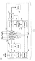
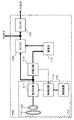
図1に、無線電力送受電システム1000の機能ブロック図を示す。無線電力送受電システム1000は、充電システム100と送電装置200からなる。
FIG. 1 shows a functional block diagram of the wireless power transmission /
充電システム100は、受電装置110と充電回路113、蓄電装置たる蓄電池114から構成される。蓄電池114はニッケル水素電池やリチウムイオン電池等が採用されうる。受電装置110は、2次共振コイル101、2次結合コイル102(本発明で云う受電コイル)、整流回路111、2次制御回路112、通信装置116(本発明で云う第2の通信部)から構成される。送電装置200は、1次共振コイル201、1次結合コイル202(本発明で云う送電コイル)、発振器211、カプラ212、検波器213、1次制御回路214、通信装置215(本発明で云う第1の通信部)から構成される。なお、2次共振コイル101、2次結合コイル102、1次共振コイル201、1次結合コイル202は単にコイル101、コイル102、コイル201、コイル202と呼ぶ場合がある。同様に、2次制御回路112、1次制御回路214は単に制御回路112、制御回路214と呼ぶ場合がある。
The charging system 100 includes a
発振器211は、商用電源(交流)や太陽電池(直流)などの外部からの電力を、コイル201とコイル101との間で共振が起こる周波数(以下、「目標共振周波数」という)の電気信号に変換してコイル202に与える。なお、目標共振周波数は、数MHz〜数十MHzの発振周波数である。ここで電気信号は電圧波形で計測されるが、電流波形であっても良い。カプラ212は発振器211とコイル202の間に介在し、発振器211からコイル202に供給される電気信号の一部を検波器213に供給する。検波器213は、供給された上記電気信号をアナログ/デジタル変換(サンプリング)し、サンプリングしたデジタル信号を制御回路214に供給する。本実施形態では電圧波形におけるサンプリングを行なう。
The
カプラ212は、コイル202に供給された電力のうちカプラ212側に反射された電気信号の一部を検波器213に供給してもよい。この場合、検波器213を介して制御回路214が反射電力を検出可能となり、この反射電力を小さくするように後述のように整合回路を調整することによって、送受電間の整合性の調整(整合性のマッチング等)に使用できる。また、反射電力が検出可能となることによって、送電装置200が受電装置110と通信をすることなく、コイル101とコイル201の間の伝送環境を間接的に把握することができる。さらに、既知の反射電力値を閾値として事前に制御回路214に与えておくことにより、反射電力の検出値が当該閾値以上となった場合には送電を自動的に停止するといったことも可能となる。
The
なお上記伝送環境は、1次側の結合コイルと共振コイル、および2次側の結合コイルと共振コイルの各々の間(図1中の符号D1、D2、D3で示される長さの部分)における空間の環境や、各コイルがコイル面において描く形状(以後単にコイルの形状と呼ぶ。例えば、曲線形状や多角形状が含まれる)、材質、各コイル面の面積(本発明で言う受電面の面積)の大きさ、各コイル間の距離(符号D1、D2、D3で示される長さ。なお、後述の伝送距離も含まれる)等で定まる。 The transmission environment is between the primary side coupling coil and the resonance coil, and between the secondary side coupling coil and the resonance coil (the lengths indicated by reference numerals D1, D2, and D3 in FIG. 1). The environment of the space, the shape that each coil draws on the coil surface (hereinafter simply referred to as the shape of the coil; for example, curved and polygonal shapes are included), the material, and the area of each coil surface (the area of the power receiving surface referred to in the present invention ), Distances between the coils (lengths indicated by reference signs D1, D2, and D3, including transmission distances described later).
制御回路214は、検波器213から供給されたデジタル信号に基づいて、発振器211からコイル202に供給されている電気信号の電圧波形の周波数と振幅を検出する。先述のように、検波器213から供給されたデジタル信号は、発振器211からコイル202に供給される電気信号の一部をサンプリングした信号である。その後、検出した周波数と振幅に基づき、コイル202に供給される電気信号の電圧波形が、目標共振周波数と目標とする振幅になるよう、発振器211を制御する。電圧波形の振幅は、伝送される電力の大きさに応じて調整される。なお、電気信号の目標共振周波数が既知の場合は、制御回路214は振幅のみを検出するものであっても良い。
The
送電コイル202は、コイル201とコイル101を介して、コイル102へ向けて無線で電力を送電する。すなわち、発振器211からコイル202に電気信号が供給されると、コイル202に磁界が発生し、この磁界に基づく電磁誘導によりコイル201に高周波電力が発生する(コイル202−コイル201間に結合係数κ2が存在する)。この高周波電力は、コイル201とコイル101との間の磁気共鳴によって、コイル101に伝送される(磁気共鳴方式の無線電力伝送。コイル201−コイル101間に結合係数κ3が存在する)。こうして伝送された電力は、電磁誘導により、コイル101からコイル102に受電される(コイル101−コイル102間に結合係数κ1が存在する。結合係数は上記伝送環境等から算出される。)。なお、伝送効率は、整流素子や寄生容量成分の影響を受けるが、その前提として、上述の伝送環境、結合係数、後述の伝送距離の影響も受ける。
The
コイル201とコイル101は、数MHz〜数10MHzの周波数帯域で共振が起こるように構成されている。本実施形態では、コイル201とコイル101は略同じ円形形状と大きさを有するものとする。なお、各コイルの形状は楕円等を含む円形である必要は無く、三角形、四角形などの多角形や曲線形状等で渦巻いているものであれば使用しうるが、本実施形態では、略円形状で渦巻き形状になっている例で説明を行なう。
The
また本実施形態では、共振コイルの大きさと結合コイルの大きさとでは共振コイルの方が大きくなっている。結合コイルの方が大きくても良いが、実験結果等から共振コイルの方が大きい方が伝送効率がよい。 In this embodiment, the resonance coil is larger in size than the resonance coil and the coupling coil. The coupling coil may be larger, but from the experimental results and the like, the larger the resonance coil, the better the transmission efficiency.
本実施形態では、1次共振コイル201、2次共振コイル101は両端がオープンとなっているLC型共振コイルである。なお、共振コイルは閉ループであってもよい。この場合は、コイル両端が単純に接続されるか、間にキャパシタが挿入される。なお、コイル102、コイル202は、閉ループのコイルである。
In the present embodiment, the
本実施形態では、送信側(1次側)と受信側(2次側)において、コイル101とコイル201、コイル102とコイル202は、巻き数、太さ、コイルの直径等については略同じ設計値、すなわち略対照的である。これは、対称とすることによって送信側と受信側とで共振周波数があわせやすいからである。なお、これらは対称的でなくても良い。
In the present embodiment, the
本実施形態において、共振コイルは数回〜十数回巻き程度であり、結合コイルは共振コイルより少なく1回〜数回巻き程度である。また、共振コイルの直径、結合コイルの直径は双方とも数cm〜数十cmオーダーであるが、共振コイルの直径は結合コイルの直径より大きく、例えば2倍〜数倍程度大きい。 In the present embodiment, the resonance coil has a few to a dozen turns, and the coupling coil is less than the resonance coil and has a turn to a few turns. In addition, the diameter of the resonance coil and the diameter of the coupling coil are both on the order of several centimeters to several tens of centimeters.
共振コイルの巻き数は、共振周波数を下げるため多めがよく、巻き方はコイルを構成する各線の間の線間容量によりいわゆるQ値が下がらないように各線の間に隙間を設ける方がよい。共振コイルの直径については、大きいほど共振周波数を下げやすいのでできるだけ大きめがよいが、一方で共振コイルが大きいと扱いがかさばるので、直径は小さいものが要求される。結合コイルの巻き数および直径は、共振コイルとの整合が調整しやすいように、すなわち共振コイルと結合コイル間の距離による整合性への影響度が鈍くなるように決定される。共振コイルと結合コイルの太さについては、高周波領域でのインピーダンスを下げるため、できるだけ太い方がよい。これは、高周波領域においては表皮効果があるからである。これらの設計値は、上記を基に理論計算や実験、または経験から得られる。 The number of turns of the resonance coil is preferably large in order to reduce the resonance frequency, and it is better to provide a gap between the lines so that the so-called Q value does not decrease due to the line capacitance between the lines constituting the coil. The larger the diameter of the resonance coil, the easier it is to lower the resonance frequency, so it is better to make it as large as possible. However, if the resonance coil is large, handling is bulky, so a small diameter is required. The number of turns and the diameter of the coupling coil are determined so that the matching with the resonance coil can be easily adjusted, that is, the influence on the matching due to the distance between the resonance coil and the coupling coil becomes dull. About the thickness of a resonance coil and a coupling coil, in order to reduce the impedance in a high frequency area, the thicker one is good. This is because there is a skin effect in the high frequency region. These design values are obtained from theoretical calculations, experiments, or experience based on the above.
上記範囲の結合コイル、共振コイルの設計値で十数W程度の無線電力伝送が可能である。なお、伝送電力が大きくなる場合は、たとえば伝送電流が大きくなるので各コイルの直径を大きくし抵抗分損失を低下させる必要がある。また、たとえば電流の時間変化率(△I/△t)が大きくなることから交流損失の低減も考慮する必要があり、各線の間の線間容量を小さくするなどする必要がある。 Wireless power transmission of about several tens of watts is possible with the design values of the coupling coil and the resonance coil in the above range. When the transmission power increases, for example, since the transmission current increases, it is necessary to increase the diameter of each coil and reduce the resistance loss. In addition, for example, since the time change rate (ΔI / Δt) of the current increases, it is necessary to consider reduction of AC loss, and it is necessary to reduce the capacitance between the lines.
コイル102は、受電した電力を整流回路111に出力する。整流回路111は、受電した交流の電力(交流電圧)を、整流して直流の電力(直流電圧)に変換し、充電装置110の外部に在る充電回路113に供給する。充電回路113は、供給された電力を蓄電池114に充電する。制御回路112は、整流回路111、充電回路113、通信装置116を制御する。例えば、制御回路112は、蓄電池114における充電状況を充電回路113を通じて監視する。
The
通信装置116(本発明における第2の通信部)と通信装置215(本発明における第1の通信部)との間では、次に述べるような送電に関する情報(送電情報)の通信が行なわれる。なお、制御回路112中には、後で述べる複数の受電コイル(コイル102−1と複数のコイル102−2)の中から任意数の受電コイルを選択する受電コイル選択部112aが存在する。
Between the communication device 116 (second communication unit in the present invention) and the communication device 215 (first communication unit in the present invention), communication related to power transmission (power transmission information) as described below is performed. In the
充電の際に、制御回路214は通信装置215を通じて通信装置116へ向けて、送電した電力に関する情報等を送信する。例えば、送電電力量や送電装置の情報(装置IDや型番、メーカ名、定格電力値など)を送電情報として送信する。なお、通信装置116と通信装置215との間の通信では、通信装置116から通信装置215に向けて情報を送信しても良い。この場合の情報は、受電装置110へ向けて送電する電力量を送電装置の制御回路214が算出する際に使用される情報であり、例えば充電中の蓄電池の状態を通知したり、所望する送電量や装置IDや型番、メーカ名、定格電力値などを送電情報として送信する。さらに、後で述べるように送信側に対して送電電力量を指定する情報であっても良い。
At the time of charging, the
通信装置116と通信装置215との間の通信では、送電側と受電側とで認証確認を行ってもよい。特定の受電装置(受電システム)にしか送電を行なわない無線電力送受電システムの場合には、こうした認証システム(たとえば制御回路112、制御回路214、通信装置116と通信装置215で構成される)が必要である。通信装置116と通信装置215との間、または通信装置116と通信装置215との間を経由した制御回路112と制御回路214との間では、お互いの装置IDや、性能(定格値、送電可能電力値や受電可能電力値など)、型番、メーカ名、課金情報等の認証情報が通信される。たとえば認証システム側(たとえば制御回路214)で指定した認証情報が一致した場合等に無線電力伝送が許可され、認証情報が一致しない場合には無線電力伝送は許可されない。なお、こうした目的を有せず単に送電受電を行なうだけであれば、例えば通信回路116、通信回路215は無くてもよい。
In communication between the
同図中には、整合回路が含まれていないが、無線電力送受電システム1000を設計した設計者や無線電力送受電システム1000を使用する使用者が結合コイルのコイル大きさ、形状、または共振コイルとの距離、共振コイル同士の距離等を調整する事により、1次結合コイル202〜1次共振コイル201〜2次共振コイル101〜2次結合コイル102の各間における整合性の調整を行うことができるので、説明の都合の上から本実施形態では整合回路は使用しない例で説明する。この各間における整合性の調整を行うことで、コイル101−コイル102間の結合係数κ1、コイル202−コイル201間の結合係数κ2、コイル201−コイル101間の結合係数κ3の各結合度を高めることができる。
Although the matching circuit is not included in the figure, the designer who designed the wireless power transmission /
なお、カプラ212−コイル202間、又はコイル102−整流回路111間の少なくとも一方に、例えば可変容量コンデンサ等を有してインピーダンスマッチングを行なうような整合回路が介在しても良い。各コイル間の空間の環境や、各コイルの形状、材質、各コイル面の面積の大きさ、各コイル間の距離等が変化する事が起こりうる場合には整合回路により整合性の調整を行う方が良い。整合回路により、送受電間のインピーダンスマッチングを行なう事ができ、例えばコイル202からカプラ212へ向けた反射波を低減することができ、送電効率が上昇する。この場合、制御回路214は、前述したコイル202に供給された電力のうち発振器211側に反射される電気信号に関する情報(たとえば反射信号の電圧振幅値など)を用いて、整合回路の可変容量コンデンサ等を調整する。コイル102−整流回路111間に挿入された整合回路は、整流回路111の出力電圧又は出力電流の情報を用いて制御回路112によって調整を受ける。
Note that a matching circuit that has a variable capacitor or the like and performs impedance matching may be interposed between at least one of the
次に図2を参照して、複数の2次結合コイルについて説明する。 Next, a plurality of secondary coupling coils will be described with reference to FIG.
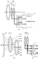
同図(a)には、リング状の2次共振コイル101、および2次結合コイル102−1(第1の受電コイル)と2次結合コイル102−2(第2の受電コイル)が階層化した状態で描かれている。すなわち、2次結合コイル102は2次結合コイル102−1と2次結合コイル102−2から構成される。コイル102−1とコイル102−2には、各々対応する整流回路111−1(本発明で云う第1の整流回路)、整流回路111−2(本発明で云う第2の整流回路)が接続されている。なお、同図では2次結合コイル、整流回路が2つを例に説明をしているが、各々3つ以上であっても良い(その場合、2次結合コイル102−k、整流回路111−kと呼ぶ。kは3以上の整数である。2次結合コイル102−kは、複数の第2の受電コイルを意味する)。
In FIG. 6A, the ring-shaped
なお、2次結合コイル、整流回路が3つ以上の場合の実施形態は、上記の2次結合コイル、整流回路が2つの場合の実施形態から容易に想到できる。 The embodiment in which there are three or more secondary coupling coils and rectifier circuits can be easily conceived from the embodiment in which there are two secondary coupling coils and rectifier circuits.
整流回路111−1、整流回路111−2の出力は合成回路111−Aに入力され、充電回路113に向けて一出力で出力される。なお、整流回路111−1、整流回路111−2の出力が、充電回路113や蓄電池114などの充電装置110の外部に向けて、その途中の線路において一本化されることがあれば(途中に合成回路111−A等が介在して一本化されてもよい)、充電回路113や蓄電池114など充電装置110の外部に向けて一出力で出力されたこととなる。
Outputs of the rectifier circuit 111-1 and the rectifier circuit 111-2 are input to the synthesis circuit 111-A and output to the charging
整流回路111−1、整流回路111−2を通じて、コイル102−1およびコイル102−2が充電した電力を充電装置110の外部に向けて一出力で出力される。これによって、1つの送電コイル202から送出された電力を階層化された複数の受電コイル102−1および/またはコイル102−2で受電して、送電コイル202から送出された電力を蓄電池114に充電する。従って、たとえばコイル102−1と整流回路111−1の組およびコイル102−2と整流回路111−2の組や、合成回路111−Aが各々別の筐体に収められていても、上述のように充電装置110の外部に向けて一出力で出力されれば、本実施形態の整流回路111を構成する。
The electric power charged by the coil 102-1 and the coil 102-2 is output to the outside of the
整流回路111−1、整流回路111−2からの各出力電圧値は略等しいと言える場合もあるが、異なると考えられる場合も多いので、合成回路111−Aにおいて整流回路111−1、整流回路111−2からの各出力電圧のずれを調整し、整流回路111−1、整流回路111−2が並列接続であることから両方の出力電力を足し合わせて次段の充電回路113へ送出する。整流回路111は、整流回路111−1、整流回路111−2、合成回路111−Aから構成される。
The output voltage values from the rectifier circuit 111-1 and the rectifier circuit 111-2 may be said to be substantially equal, but are often considered to be different, so the rectifier circuit 111-1, the rectifier circuit in the synthesis circuit 111-A. The deviation of each output voltage from 111-2 is adjusted, and since the rectifier circuit 111-1 and the rectifier circuit 111-2 are connected in parallel, both output powers are added and sent to the charging
合成回路111−Aにおいて整流回路111−1、整流回路111−2からの各出力電圧のずれを調整する必要がある理由は、整流回路111−1、整流回路111−2からの各出力をワイヤードORしてしまうと、出力電圧が高い一方の整流回路から出力電圧が低い他の整流回路へ給電してしまうことになり、合成回路111−Aからの出力を十分確保できなくなったり、上記他の整流回路を破損させる可能性もあるからである。合成回路111−Aにおいて整流回路111−1、整流回路111−2からの各出力電圧のずれを調整し、技術常識からみて等しいとみなせるようにすることによって、こうした課題を解決し、合成回路111−Aからの出力をロス少なく十分に確保することができる。 The reason why the output voltage from the rectifier circuit 111-1 and the rectifier circuit 111-2 needs to be adjusted in the synthesis circuit 111-A is that the outputs from the rectifier circuit 111-1 and the rectifier circuit 111-2 are wired. If the OR operation is performed, power is supplied from one rectifier circuit having a high output voltage to another rectifier circuit having a low output voltage, and sufficient output from the synthesis circuit 111-A cannot be secured. This is because the rectifier circuit may be damaged. The synthesis circuit 111-A solves these problems by adjusting the deviations of the output voltages from the rectifier circuit 111-1 and the rectifier circuit 111-2 so that they can be regarded as equal in view of common technical knowledge. The output from -A can be sufficiently secured with little loss.
なお、第1の整流回路からの出力電圧と第2の整流回路からの出力電圧が大きく異ならないことが分かっている場合は、上記の課題の影響は小さいので、合成回路111−Aは、第1の整流回路からの出力電圧と第2の整流回路からの出力電圧を足し合わせて出力できる構成であればよいので、たとえば整流回路111−1、整流回路111−2からの各出力をワイヤードORする単なる結線部であってもよい。 Note that when it is known that the output voltage from the first rectifier circuit and the output voltage from the second rectifier circuit are not significantly different from each other, the effect of the above problem is small. Since the output voltage from the first rectifier circuit and the output voltage from the second rectifier circuit may be added together, the outputs from the rectifier circuit 111-1 and the rectifier circuit 111-2 are, for example, wired OR. It may be a simple connection part.
同図(a)では、コイル102−1とコイル102−2は略同じ円形形状と略同じ大きさを有するとしている。またコイル102−1の中心(本実施形態では、コイルの円形状の中心)を通り同受電コイルが接する面(以下、コイルが接する面のことをコイル面と呼ぶ)に直行する軸線L2、および、コイル102−2の(円形状の)中心を通りコイル面に直行する軸線L3は、コイル101の(円形状の)中心を通りコイル面に直行する軸線L1と一致し、各コイルのコイル面は異なる面であり、本実施形態では平行となっている。
In FIG. 6A, the coil 102-1 and the coil 102-2 have substantially the same circular shape and substantially the same size. In addition, an axis L2 that passes through the center of the coil 102-1 (in this embodiment, the center of the circular shape of the coil) and is in contact with the surface that contacts the power receiving coil (hereinafter, the surface that contacts the coil is referred to as the coil surface); The axis L3 passing through the (circular) center of the coil 102-2 and orthogonal to the coil surface coincides with the axis L1 passing through the (circular) center of the
なお、コイル102−1とコイル102−2の各軸線は同図(b)のようにずれていても良い。すなわち、たとえばコイル102−1とコイル102−2が、平面視(平面図を視覚しうる視線)において略重なる、または一部重なる位置関係である。コイル102−1とコイル102−2の位置関係は、コイル101、コイル201を介してコイル202から出力された磁束であってコイル102−1を貫く磁束の全て又は一部が、コイル102−2を貫くような位置関係であるが、同図(b)の場合、コイル102−1を貫く磁束の一部がコイル102−2を貫くような位置関係で配置されることとなる。なお、同図(b)では、L2がL3よりもL1に近い位置関係にあるが、これらの間の遠近はこれに限られない。同図(b)では、コイル102−1を貫く磁束の一部B3〜B8がコイル102−2を貫くような位置関係が示されている。なお、コイル102−1を貫く磁束がコイル102−2を少しでも貫いていれば、全て、コイル102−1を貫く磁束の一部B3〜B8がコイル102−2を貫くような位置関係と言うことができる。
Note that the axes of the coil 102-1 and the coil 102-2 may be shifted as shown in FIG. That is, for example, the coil 102-1 and the coil 102-2 are in a positional relationship in which the coils 102-1 and the coils 102-2 substantially overlap or partially overlap in a plan view (line of sight in which a plan view can be seen). The positional relationship between the coil 102-1 and the coil 102-2 is that the magnetic flux output from the
なお、コイル102−1とコイル102−2の各軸線はコイル101の軸線L1とずれていても良い。各コイルのコイル面が平行でなく、少し傾いていてもよい。すなわち、たとえばコイル102−1とコイル102−2が平面視において重なっているが、コイル102−1とコイル102−2の各々のコイル面が平行ではない関係、つまり各コイル面が傾いている関係であってもよい。また、たとえばコイル102−1とコイル102−2が平面視において重なっていないが、コイル102−1とコイル102−2の各々のコイル面が平行ではない関係、つまり各コイル面が傾いている関係であってもよい。
Each axis of the coil 102-1 and the coil 102-2 may be shifted from the axis L1 of the
何れにおいても、技術常識を参酌して、コイル102−1を貫く磁束の一部がコイル102−2を貫くような位置関係であればよい。 In any case, the positional relationship may be such that a part of the magnetic flux penetrating the coil 102-1 penetrates the coil 102-2 in consideration of common technical knowledge.
本実施形態では、結合コイル102−1と各結合コイル102−n(nは2以上の整数)の間では、微差程度の傾きのずれでは各コイルのコイル面は平行であるとする。加えて、コイル102−1とコイル102−nは同じ形状ではなくてもよく、または、同じ面積ではなくてもよいが、本実施形態では、コイル102−1とコイル102−nの形状、面積は微差のずれ程度では一致しているとし、軸線L1,L2,L3は微差のずれ程度では一致しているとみなす。 In this embodiment, between the coupling coil 102-1 and each coupling coil 102-n (n is an integer of 2 or more), it is assumed that the coil surfaces of each coil are parallel with a slight deviation in inclination. In addition, the coil 102-1 and the coil 102-n do not have to have the same shape or the same area, but in the present embodiment, the shape and area of the coil 102-1 and the coil 102-n Are assumed to be coincident with each other with a slight difference deviation, and the axes L1, L2, and L3 are regarded as coincident with each other.
コイルが接する面(受電面)をコイル面と呼んだが、例えば電線のコイルを構成する部分全体が接する面のことである。コイルを机上においた場合に、コイル全体が机に接する場合はこの机の面をコイルが接する面とすることができる。なお、コイルが歪んでいる事などの要因により厳密には一つの面に接していないとみなしうる場合には、技術常識からそのコイル全体がその面に接していると捉えても同等の効果が得られると考える事ができる範囲において、例えばその捉えられた面をもってコイルが接する面とみなす。また、コイル面の面積とは、電線の太さをゼロと考えた場合の閉ループであるコイルによってその面上で構成される図形の面積の事である。 Although the surface (power receiving surface) with which the coil contacts is called the coil surface, for example, it is the surface with which the entire part constituting the coil of the electric wire contacts. When the coil is placed on a desk, if the entire coil is in contact with the desk, the surface of the desk can be used as the plane in contact with the coil. If it can be considered that the coil is not in contact with one surface strictly due to factors such as the coil being distorted, the same effect can be obtained even if it is considered that the entire coil is in contact with the surface from the technical common sense. In a range where it can be considered to be obtained, for example, the captured surface is regarded as a surface in contact with the coil. The area of the coil surface is the area of a figure formed on the surface by a coil that is a closed loop when the thickness of the electric wire is considered to be zero.
同図(a)〜(c)には、第1の受電コイルである受電コイル102−1が接する面と、第2の受電コイルである受電コイル102−2が接する面とが異なっている状態が表されている。ここで言う面と面とが異なるという意味は、各面が同一面上に無いことを示しており(すなわちコイル102−1とコイル102−2が同一面上に存在しない)、同図(b)のように、コイル102−1を貫く磁束の全て又は一部がコイル102−2を貫くような位置関係において、コイル102−1とコイル102−2が配置されることから、本実施形態では例えば各面が層状または階層的に位置していることを示す。なお以下において、同図(a)および(b)に記載の受電コイル102−1および受電コイル102−nの関係を積層または階層と呼ぶ場合がある。 In the same figure (a)-(c), the state where the receiving coil 102-1 which is the first receiving coil is in contact with the surface where the receiving coil 102-2 which is the second receiving coil is in contact is different. Is represented. The meaning that the surface differs here means that the surfaces are not on the same surface (that is, the coil 102-1 and the coil 102-2 do not exist on the same surface). ), The coil 102-1 and the coil 102-2 are arranged in such a positional relationship that all or part of the magnetic flux passing through the coil 102-1 passes through the coil 102-2. For example, it shows that each surface is located in layers or hierarchically. In the following description, the relationship between the power receiving coil 102-1 and the power receiving coil 102-n described in FIGS.
同図の構成により、本実施形態では、送電装置200の送電コイル202は、受電装置110の受電コイル102−1(第1の受電コイル)または受電コイル102−2(第2の受電コイル)へ向けて無線で電力を送電する。また、少なくとも整流回路111−1(第1の整流回路)または整流回路111−2(第2の整流回路)のうちの一つを通じて、少なくとも第1の受電コイルまたは第2の受電コイルのうちの一つが受電した電力を充電回路113を通じて蓄電池114(蓄電装置)に出力する事によって、受電装置110が受電した電力を蓄電池114に充電する。
With this configuration, in this embodiment, the
整流回路111−1、111−2には、各々スイッチSW1、SW2が含まれており、当該スイッチを開、閉(オン、オフ)することによって、第1の受電コイル102−1や第2の受電コイル102−2から合成回路111−Aへ電力を伝送するかしないかを選択できる。すなわち、送電される電力量に応じて複数ある2次結合コイルの一部のみの使用、または全ての使用を切り換える事ができる。当該受電コイルの選択は受電コイル選択部112aが行う。同図(a)においてSW1、SW2は直列に介在しているが、同図(c)のようにSW1,SW2はコイル102−1、コイル102−2に対して並列であっても良い。
The rectifier circuits 111-1 and 111-2 include switches SW1 and SW2, respectively. By opening and closing (on and off) the switches, the first power receiving coil 102-1 and the second Whether to transmit power from the power receiving coil 102-2 to the combining circuit 111-A can be selected. That is, it is possible to switch between the use of only a part of the plurality of secondary coupling coils or the use of all of them according to the amount of power transmitted. The receiving
なお本実施形態では、結合コイルがn個以上の複数存在しえるが(nは2以上の整数)、数が多ければ多いほど良いという訳ではない。結合コイルの数は、整流素子の性能や送受電電力量等に依存して決定される。 In this embodiment, there can be a plurality of n or more coupling coils (n is an integer of 2 or more), but the larger the number, the better. The number of coupling coils is determined depending on the performance of the rectifying element, the amount of transmitted and received power, and the like.
すなわち、コイルの数が多くなるにつれて各結合コイルからの出力電圧が小さくなるため、この各出力電圧に対する整流素子の順方向電圧の割合が大きくなり、この結果として整流効率が低下するからである。また、結合コイルからの出力電圧が順方向電圧より小さくなると整流素子で整流できなくなることもおこる。 That is, as the number of coils increases, the output voltage from each coupling coil decreases, so the ratio of the forward voltage of the rectifying element to each output voltage increases, resulting in a decrease in rectification efficiency. In addition, when the output voltage from the coupling coil becomes smaller than the forward voltage, the rectifying element cannot be rectified.
一方、結合コイルの数が少なくなるにつれて結合コイル一つあたりの受電電力が大きくなるので、よりサイズの大きい整流素子が必要となり、整流素子における寄生容量成分が増加するため、高周波領域における整流効率が低下する。よってこれらの事を勘案して、所定の数の結合コイルが選定される。 On the other hand, since the received power per coupling coil increases as the number of coupling coils decreases, a larger rectifying element is required, and the parasitic capacitance component in the rectifying element increases. descend. Therefore, a predetermined number of coupling coils are selected in consideration of these matters.
[作用効果]
以上の構成により、送電側から送られた電力を複数の2次結合コイル(本実施形態ではコイル102−1、102−2)で受電し、一つの合成回路に出力し、一つの充電回路に出力するので、各コイルの受電量は総送電量よりも小さくでき、対応する整流回路における受電効率の低下を削減する事ができる。
[Function and effect]
With the above configuration, the power transmitted from the power transmission side is received by a plurality of secondary coupling coils (in this embodiment, coils 102-1 and 102-2), output to one synthesis circuit, and to one charging circuit. Since the power is output, the amount of power received by each coil can be made smaller than the total amount of power transmitted, and the reduction in power reception efficiency in the corresponding rectifier circuit can be reduced.
即ち、スイッチSW1、SW2をオンすることにより結合コイル102−1、102−2の両方を使用可能とした場合、送電側からの送電電力Wsがコイル102−1とコイル102−2とで配分して受電される。コイル102−1の受電電力をWr1、コイル102−2の受電電力をWr2と表すと、Ws=Wr1+Wr2となる(受電側が漏れなく受電したとする)。ここでWr1<Ws、およびWr2<Wsであるので、送電側から大きい電力を送電したとしても、各結合コイル102−1、102−2および各整流回路111−1、111−2が受電する電力は小さくすることが出来る。なお、結合コイル102−1、102−2が近接する場合は、理想的にはWr1=Wr2=Ws/2となるが、通常は若干差が生じWr1>Wr2となる場合が多い。結合コイルと整流回路の組が増加するにつれて、各結合コイル、各整流回路が受電する電力はより小さくすることが出来る。 That is, when both the coupling coils 102-1 and 102-2 can be used by turning on the switches SW1 and SW2, the transmission power Ws from the power transmission side is distributed between the coils 102-1 and 102-2. Is received. When the received power of the coil 102-1 is expressed as Wr1, and the received power of the coil 102-2 is expressed as Wr2, Ws = Wr1 + Wr2 is assumed (assuming that the power receiving side receives power without leakage). Here, since Wr1 <Ws and Wr2 <Ws, even if a large amount of power is transmitted from the power transmission side, the power received by each coupling coil 102-1 and 102-2 and each rectifier circuit 111-1 and 111-2. Can be made smaller. When the coupling coils 102-1 and 102-2 are close to each other, ideally, Wr1 = Wr2 = Ws / 2, but usually there is a slight difference and Wr1> Wr2. As the number of pairs of coupling coils and rectifier circuits increases, the power received by each coupling coil and each rectifier circuit can be reduced.
よって、本実施形態のような複数の結合コイルと整流回路を使用しない場合と比べて、整流回路における整流素子のサイズを小さくすることに伴い、接合容量のより小さい素子を使用することが出来、高周波特性を改善する事が出来る。また順方向電圧がより小さい整流素子を用いる事ができる。これらの事から、本実施形態では、整流効率の低下を抑制する事ができ、無線電力伝送方式における受電装置において電力伝送効率を改善させた、充電システム、無線電力送受電システム及び受電装置を提供する事ができる。また、複数の結合コイルを図2のように積層して構成できることから、受電装置のコイル面方向のサイズ増加を低減させることができる。 Therefore, as compared with the case of not using a plurality of coupling coils and a rectifier circuit as in this embodiment, it is possible to use an element with a smaller junction capacitance as the size of the rectifier element in the rectifier circuit is reduced. High frequency characteristics can be improved. Further, a rectifying element having a smaller forward voltage can be used. For these reasons, the present embodiment provides a charging system, a wireless power transmission / reception system, and a power receiving device that can suppress a decrease in rectification efficiency and improve the power transmission efficiency in the power receiving device in the wireless power transmission method. I can do it. In addition, since a plurality of coupling coils can be stacked as shown in FIG. 2, an increase in the size of the power receiving device in the coil surface direction can be reduced.
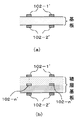
ここで、複数の結合コイルを積層して構成する場合の一例について述べる。例えば、2つの結合コイルを基板の表面と裏面の両面に備えることで(図3(a))、結合コイルの寸法をコンパクト化することが出来る。また、複数の結合コイルを多層積層基板の表面、裏面、内層部の各層の何れかのうちの2以上の層に備えることができる(図3(b)では基板の表面、裏面、および内層に存在)。同図(a)、(b)は、基板の法線を含む面において基板を切断して切断面を側面から見た図であり、m回巻き(mは自然数)のリング状の結合コイル102−1、結合コイル102−2、結合コイル102−nの断面が各々符号102−1’、断面102−2’、断面102−n’によって示されている断面(同図中の斜線部)で表されている。各結合コイルは既に述べた設計値のコイルである。
Here, an example in which a plurality of coupling coils are stacked will be described. For example, by providing two coupling coils on both the front and back surfaces of the substrate (FIG. 3A), the size of the coupling coil can be reduced. In addition, a plurality of coupling coils can be provided on two or more of the front, back, and inner layers of the multilayer laminated substrate (in FIG. 3B, the front, back, and inner layers of the substrate). Existence). FIGS. 4A and 4B are views in which the substrate is cut along the plane including the normal line of the substrate and the cut surface is viewed from the side, and the ring-shaped
この場合、受電側が漏れなく受電したとすると、Ws=ΣWriであり(iは自然数、Σはi=1からnまでの和を表す)、Wri<Wsは明らかである(i=1〜n)。すなわち上で述べたように、この例では、整流効率の低下を抑制する事ができ、無線電力伝送方式における受電装置において電力伝送効率を改善させた、充電システム、無線電力送受電システム及び受電装置を提供する事ができる。また、複数の結合コイルを図3のように積層して構成できることから、受電装置のコイル面方向のサイズ増加を低減させることができる。 In this case, assuming that the power receiving side has received power without leakage, Ws = ΣWri (i is a natural number, Σ represents the sum from i = 1 to n), and Wri <Ws is clear (i = 1 to n). . That is, as described above, in this example, a charging system, a wireless power transmission / reception system, and a power reception device that can suppress a decrease in rectification efficiency and improve power transmission efficiency in a power reception device in a wireless power transmission system. Can be provided. In addition, since a plurality of coupling coils can be stacked as shown in FIG. 3, an increase in size in the coil surface direction of the power receiving device can be reduced.
[変形例]
各層の結合コイル102−1、結合コイル102−2、結合コイル102−nの各々の面積は互いに等しくなくてもよいと上で述べたが、例えば、各層の結合コイルのコイル面の面積を異ならせることにより各結合コイルの受電電力Wri(i=1〜n)を等しくせず所望の値となるように調整してもよい。この場合、結合コイル102−nに対応するスイッチSWnを各々切り替えることにより各結合コイルの組み合わせを調整する事ができ、受電量の組み合わせを増やす事ができる。こうすることによって、送電される電力が複数パターンあったとしても、受電する結合コイルの組み合わせを調整することによって対応する事ができる。
[Modification]
Although it has been described above that the areas of the coupling coil 102-1, the coupling coil 102-2, and the coupling coil 102-n of each layer do not have to be equal to each other, for example, the areas of the coil surfaces of the coupling coils of each layer are different. The received power Wri (i = 1 to n) of each coupling coil may be adjusted to be a desired value without being equalized. In this case, the combination of each coupling coil can be adjusted by switching each switch SWn corresponding to the coupling coil 102-n, and the combination of the amount of received power can be increased. By doing so, even if there are a plurality of patterns of electric power to be transmitted, it can be dealt with by adjusting the combination of coupling coils to receive power.
なお、送電される電力量は、たとえば送電側の通信装置215から先述の送電情報に送電電力量が載せられて送信され、受電側の通信装置116で受信されることによって知る事ができる。この場合に、実際の受電量と送電情報中の送電電力量との差が所定の閾値より大きい場合は、共振コイル201、101間の送電状態が悪いと考えられ、受電側で受電する結合コイルを適応的に変更する。実際の受電量は受電電力検出部たる制御回路112が整流回路111−n(nは自然数)を通じて検出する。すなわち、送電情報中の送電電力量から受電側の制御回路(受電コイル選択部)112は結合コイル102−1、結合コイル102−2、結合コイル102−3の3つで受電するようSW1、SW2、SW3をオンにしていたが(結合コイル102−1、結合コイル102−2、結合コイル102−3はこの順に共振コイル101に近いとする。以下同じ)、結合コイル102−3の受電量がゼロとみなせる場合、もしくは送電電力量が結合コイル102−1および102−2の2つで受電できる大きさであると判断される場合には、結合コイル102−3のSW3をオフにする。
Note that the amount of transmitted power can be known, for example, by transmitting the amount of transmitted power from the
また、充電方式の違いによって、受電する結合コイルを使い分けてもよい。充電方式には、例えば急速充電方式(本発明で云う第1の充電方式)と、急速充電方式より充電速度が低い通常充電方式(本発明で云う第2の充電方式)とがある。すなわち、急速充電の場合は共振コイル101に近い結合コイル102−1のみを使用し、大電流の急速充電の場合は全ての結合コイルを使用し、通常充電の場合は図2のような共振コイル101から離れた結合コイル102−2のみを使用するなどと使い分ける。
Moreover, you may use properly the coupling coil which receives electric power by the difference in a charging system. The charging method includes, for example, a rapid charging method (first charging method referred to in the present invention) and a normal charging method (second charging method referred to in the present invention) having a charging speed lower than that of the rapid charging method. That is, only the coupling coil 102-1 close to the
図4(a)に示したように、急速充電用コイルと通常充電用コイルは伝送距離に応じて伝送効率が変化する。同図(a)には、共振コイル101に近い結合コイル102−1のみを使用した場合と、共振コイル101から離れた結合コイル102−2のみを使用した場合の、各コイルの伝送距離に対する伝送効率特性が示されている。共振コイル101に近い結合コイルを急速充電用に用い、共振コイル101から遠い結合コイルを通常充電用に用いるのが好適である。本実施形態では伝送距離は、共振コイル201の中心と共振コイル101の中心との間の距離(共振コイル201、101の各コイルが接する平面が平行な場合はそれら平面間の距離)、すなわち共振コイル201、101間の距離のことであるが、他に各コイル間の任意の距離であってもよく、例えば結合コイル102、202間の距離であってもよい。共振コイルを有さない電磁誘導型や電波受信型、他の共鳴型の充電システムでは、送電コイル(結合コイル202に相当)、受電コイル(結合コイル102に相当)間の距離となる。なお、コイルの中心とは例えばコイルの重心位置などとすることができる。
As shown in FIG. 4A, the transmission efficiency of the quick charging coil and the normal charging coil varies depending on the transmission distance. In FIG. 9A, transmission with respect to the transmission distance of each coil when only the coupling coil 102-1 close to the
同図(a)によると、伝送距離は所定の値の距離(同図では例えば20cmの例)までは急速充電用コイルの方が伝送効率はよいが、伝送距離が所定の距離を超えると通常充電用コイルの方が伝送効率がよい。よって伝送距離が所定の距離20cmよりも小さい場合には急速充電方式で充電を行い、伝送距離が20cmよりも大きい場合には通常充電方式で充電を行うようにしてもよい。また、送電側の1次共振コイル201と受電側の2次共振コイル101の距離Dを超音波センサなどの距離センサ等(同図(b)には距離センサ220で図示)で計測し、急速充電を行う場合に伝送距離が20cm以上だった場合には、表示部(同図(b)には出力部120で図示)に充電装置110を送電装置200へ近づけるよう使用者へ促す表示などをして伝送距離を20cm以下とさせて急速充電するようにしてもよい。また、通常充電の場合に伝送距離が20cm以下の場合は、表示部に伝送距離を20cm以上とするように使用者へ促す表示などをして伝送距離を20cm以上とさせて通常充電するようにしてもよい。なお、通常充電においては伝送距離を不問とする場合は何も表示をしなくてもよい。なお、伝送距離を距離センサで検出する代わりに、送電情報から得られた送電電力(量)と受電電力(量)を比較して伝送効率を算出することで、急速充電か、通常充電かを選択するようにしてもよい。
According to (a), the transmission distance is better for the quick charging coil up to a predetermined distance (for example, 20 cm in the figure), but it is normal if the transmission distance exceeds the predetermined distance. The charging coil has better transmission efficiency. Therefore, when the transmission distance is smaller than the predetermined distance of 20 cm, charging may be performed using the quick charging method, and when the transmission distance is larger than 20 cm, charging may be performed using the normal charging method. Further, the distance D between the
こうした充電方式の判断を行なう充電判断部112bは、例えば2次側制御回路112内に存在する。
The
上では、伝送距離の所定の値の距離が20cmの場合の例で説明したが、たとえば電動自転車などの軽車輛等の場合はこれでよいが、ハイブリッド車、電気自動車などの電動車両の場合は、車長が軽車輛よりも大きいことから伝送距離を50cmなどと大きい値としてもよい。この所定の値は、既に述べた結合係数等から定められる。 In the above, the example of the case where the distance of the predetermined value of the transmission distance is 20 cm has been described. However, this is sufficient in the case of a light vehicle such as an electric bicycle, but in the case of an electric vehicle such as a hybrid vehicle and an electric vehicle. Since the vehicle length is larger than that of the light vehicle, the transmission distance may be set to a large value such as 50 cm. This predetermined value is determined from the coupling coefficient already described.
これまで述べてきたような充電の際には、受電側の制御回路112は、蓄電池114に対する充電状況を充電回路113を通じて監視し、所望する送電電力に関する送電情報を、通信装置116を介して通信装置215に送信してもよい。通信装置215は、受信した送電情報を制御回路214に送る。制御回路214は、制御回路112から要求された電力になるよう、発振器211の振幅を調整する。
At the time of charging as described above, the
蓄電池114が満充電になると、制御回路112は、その旨を示す送電情報を、通信装置116を介して通信装置215に送信する。通信装置215は、受信した情報を制御回路214に送る。これを受けて、制御回路214は、発振器211を停止させる。これにより、電力伝送を終了させるようにしてもよい。
When the
<<第2実施形態>>
図5に本実施形態に係る電源装置を示す。図1との違いについて主に述べ、図1と同じ部分は先の実施形態での説明と同じでありここでの説明は省略する。
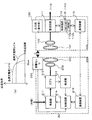
<< Second Embodiment >>
FIG. 5 shows a power supply device according to this embodiment. Differences from FIG. 1 are mainly described, and the same parts as those in FIG. 1 are the same as those described in the previous embodiment, and the description thereof is omitted here.
本実施形態の充電システム100aは、整流回路111の出力または蓄電池114からの出力を受けて、電圧を所定の値に変換して出力する直流−直流コンバータであるDC/DC121を備える電源装置100aである。DC/DC121の出力(直流電力)は図示しないコンセント等から外部へ出力可能である。DC/DC121は、蓄電池114から出力された電力を直流のDC出力にして外部へ出力するための出力部である。
The
使用者は送電装置200から電源装置100aの蓄電池114に充電することで、送電装置200から離れて、商用電源から電源を得ることが困難な土地において電源装置100aをポータブル直流電源として使用する事ができる。
By charging the
[作用効果]
実施形態1と同様に、本実施形態においても、整流効率の低下を抑制する事ができ、無線電力伝送方式における受電装置において電力伝送効率を改善させた電源装置を提供する事ができる。
[Function and effect]
Similar to the first embodiment, also in this embodiment, it is possible to suppress a decrease in rectification efficiency, and it is possible to provide a power supply device in which the power transmission efficiency is improved in the power receiving device in the wireless power transmission method.
[変形例]
図6に本実施形態に係る電源装置を示す。図5との違いについて主に述べ、図5と同じ部分は先の実施形態での説明と同じでありここでの説明は省略する。
[Modification]
FIG. 6 shows a power supply device according to this embodiment. Differences from FIG. 5 are mainly described, and the same parts as those in FIG. 5 are the same as those described in the previous embodiment, and the description thereof is omitted here.
本実施形態の充電システム100bは、DC/DC121の出力を受けて、直流電力を交流電力に変換して出力する直流−交流インバータであるDC/AC122を備える電源装置100bである。DC/AC122の出力(交流電力)は図示しないコンセント等から外部へ出力可能である。DC/DC121は、蓄電池114から出力された電力を直流のDC出力にして外部へ出力するための出力部である。また、DC/AC122は、蓄電池114から出力された電力を交流のAC出力にして外部へ出力するための出力部である。よって、本実施形態の電源装置100bは、蓄電池114から出力された電力をAC出力またはDC出力にして外部へ出力するための出力部を有している。なお、電源装置100bは、DC/AC122のみを有し、AC出力でのみ外部へ出力するものであってもよい。
The
使用者は送電装置200から電源装置100bの蓄電池114に充電することによって、送電装置200から離れて、商用電源から電源を得ることが困難な土地において電源装置100bをポータブル交流電源として使用する事ができる。
By charging the
<<第3実施形態>>
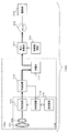
図7に本実施形態に係る移動体1100を示す。具体的には電気をエネルギー源とする電動車輛を例に説明を行う。電動車輛にはハイブリッド車、プラグインハイブリッド車、電気自動車、電動自転車(電動バイク)等が含まれる。なお、電動アシスト自転車、電動船舶、電動飛行機、歩行ロボット、エレベータ等の他の移動体の実施形態は本実施形態から容易に想到できるので説明は省略する。ここでは、図1との違いについて主に述べ、図1と同じ部分は先の実施形態での説明と同じでありここでの説明は省略する。
<< Third Embodiment >>
FIG. 7 shows a moving
本実施形態の充電システム100cは、蓄電池114に蓄えた電力を外部に出力できるバッテリシステム100cである。出力(直流電力)は図示しないコネクタ等から外部へ出力される
当該出力は、例えば直流−直流コンバータ、直流−交流インバータ等を含む電力変換部311を通じて動力源たるモーター312に供給される。当該動力源は、蓄電池114から出力された電力を電動車輛本体(本発明の本体部)を移動させる動力へと変換する変換部である。モーター312が駆動輪たる駆動部313を駆動することで、電動車輛本体が移動する。アクセルおよびブレーキである加減速制御部314からの指令により、電力変換部311からの供給電力が増減し、モーター312、駆動部313の回転が加減速する。
The
なお、電動アシスト自転車では、加減速制御部314は、人力へのアシスト動作の印加、停止の制御部である。電動船舶では、モーター312はスクリューたる駆動部313を駆動し、加減速制御部314は、モータの加速のみの有無の指示を行う。なお、モータを停止させれば船舶は自動的に減速し、停止する。電動飛行機では、モーター312はプロペラたる駆動部313を駆動し、加減速制御部314は、モータの加速のみの有無の指示を行う。なお、モータを停止させれば飛行機は自動的に減速し、停止する。歩行ロボットでは、モーター312は歩行足たる駆動部313を駆動し、加減速制御部314は、歩行動作の開始、停止の制御部である。エレベータでは、エレベータ籠の昇降用モータであるモーター312が昇降用プーリーたる駆動部313を駆動し、加減速制御部314は、エレベータ籠の上昇または下降の加減速を制御する。 使用者は送電装置200から充電システム(バッテリシステム)100cの蓄電池114に無線充電することによって、電動車輛の充電をする際に充電ケーブルを充電器から電動車輛へ接続する煩わしさから解放される。
In the electrically assisted bicycle, the acceleration /
[作用効果]
実施形態1と同様に、本実施形態においても、整流効率の低下を抑制する事ができ、無線電力伝送方式における受電装置において電力伝送効率を改善させた移動体を提供する事ができる。
[Function and effect]
Similar to the first embodiment, also in this embodiment, a decrease in rectification efficiency can be suppressed, and a mobile body with improved power transmission efficiency can be provided in a power receiving apparatus in a wireless power transmission system.
尚、各実施形態の説明文中に示した具体的な数値や構成などは、単なる例示であって、当然の如く、それらを様々な数値や構成等に変更することができる。
It should be noted that the specific numerical values and configurations shown in the description of each embodiment are merely examples, and can naturally be changed to various numerical values and configurations.
100、100a、100b 充電システム
101 2次共振コイル
102 2次結合コイル(受電コイル)
102−1、102−1’ 2次結合コイル(第1の受電コイル)
102−2、102−2’、102−n、102−n’ 2次結合コイル(第2の受電コイル)
110 受電装置
111、111−1、111−2 整流回路
111−A 合成回路
112 2次制御回路
113 充電回路
114 蓄電池(蓄電装置)
116 通信装置(第2の通信部)
120 出力部
121 DC/DC(直流−直流コンバータ)
122 DC/AC(直流−交流インバータ)
200 送電装置
201 1次共振コイル
202 1次結合コイル(送電コイル)
211 発振器
212 カプラ
213 検波器
214 1次制御回路
215 通信装置(第1の通信部)
220 距離センサ
311 電力変換部
312 モータ(動力源)
313 駆動輪(駆動部)
314 加減速制御部
1000 無線電力送受電システム
1100 電動車両(移動体)
SW1、SW2 スイッチ
100, 100a,
102-1 and 102-1 ′ secondary coupling coil (first power receiving coil)
102-2, 102-2 ', 102-n, 102-n' secondary coupling coil (second receiving coil)
DESCRIPTION OF
116 Communication device (second communication unit)
120
122 DC / AC (DC-AC inverter)
200
220
313 Drive wheel (drive unit)
314 Acceleration /
SW1, SW2 switch
Claims (10)
蓄電装置と、
前記受電装置が受電した電力を前記蓄電装置に充電する充電回路とを備え、
前記受電装置は、
前記電力を受電する第1の受電コイルと、第2の受電コイルとを有し、
前記第1の受電コイルには第1の整流回路が接続され、かつ、前記第2の受電コイルは第2の整流回路が接続され、
前記第1の受電コイルと前記第2の受電コイルは、前記第1の受電コイルが接する面と前記第2の受電コイルが接する面が異なり、かつ、前記第1の受電コイルを貫く磁束の全て又は一部が前記第2の受電コイルを貫くような位置関係で配置されており、
前記第1の整流回路および前記第2の整流回路を通じて、前記第1の受電コイルおよび前記第2の受電コイルが受電した電力を前記充電回路に向けて一出力で出力する事によって、前記受電装置が受電した電力を前記蓄電装置に充電する
充電システム。
A power receiving device that receives power transmitted wirelessly from the power transmitting device;
A power storage device;
A charging circuit for charging the power storage device with the power received by the power receiving device,
The power receiving device is:
A first power receiving coil that receives the power and a second power receiving coil;
A first rectifier circuit is connected to the first power receiving coil, and a second rectifier circuit is connected to the second power receiving coil,
The first power receiving coil and the second power receiving coil are different in the surface in contact with the first power receiving coil and the surface in contact with the second power receiving coil, and all of the magnetic flux penetrating the first power receiving coil. Alternatively, a part of the second receiving coil is disposed so as to penetrate the second power receiving coil,
By outputting the power received by the first power receiving coil and the second power receiving coil to the charging circuit with one output through the first rectifier circuit and the second rectifier circuit, the power receiving device The charging system charges the power storage device with the power received by the battery.
請求項1に記載の充電システム。
The charging system according to claim 1, wherein the power receiving device includes a substrate, and the first power receiving coil and the second power receiving coil exist on both surfaces of the substrate.
請求項1または2に記載の充電システム。
The area of the shape drawn by the first power receiving coil on the surface in contact with the first power receiving coil is different from the area drawn by the second power receiving coil on the surface in contact with the second power receiving coil. 2. The charging system according to 2.
前記送電コイルの中心と前記第1の受電コイルの中心との間の距離、または前記送電コイルの中心と前記第2の受電コイルの中心との間の距離である伝送距離を検出し、
前記伝送距離が所定の値よりも小さい場合には第1の充電方式を用いて充電を行い、前記伝送距離が所定の値よりも大きい場合には前記第1の充電方式と比べて充電速度が低い第2の充電方式を用いて充電を行う判断を行う充電判断部
を備えた請求項1から3の何れかに記載の充電システム。
The power transmission device includes a power transmission coil that wirelessly transmits power toward the first power receiving coil or the second power receiving coil of the power receiving device,
Detecting a transmission distance that is a distance between the center of the power transmission coil and the center of the first power reception coil or a distance between the center of the power transmission coil and the center of the second power reception coil;
When the transmission distance is smaller than a predetermined value, charging is performed using the first charging method, and when the transmission distance is larger than a predetermined value, the charging speed is higher than that of the first charging method. The charging system according to any one of claims 1 to 3, further comprising a charging determination unit that determines to perform charging using a low second charging method.
前記受電電力検出部において検出された受電電力に基づき、前記第1の受電コイルまたは複数の前記第2の受電コイルの中から受電する受電コイルを選択する受電コイル選択部を備える
請求項1から4の何れかに記載の充電システム。
A received power detection unit that detects received power received by the power receiving device;
5. A receiving coil selection unit that selects a receiving coil to receive power from the first receiving coil or the plurality of second receiving coils based on the received power detected by the received power detection unit. The charging system according to any one of the above.
前記第2の通信部が前記第1の通信部から前記通信によって取得した前記送電装置が送電した電力に関する情報に基づき、前記第1の受電コイルまたは複数の前記第2の受電コイルの中から受電する受電コイルを選択する受電コイル選択部を備える
請求項1から4の何れかに記載の充電システム。
A second communication unit that communicates with the first communication unit provided in the power transmission device;
The second communication unit receives power from the first power receiving coil or the plurality of second power receiving coils based on information about the power transmitted by the power transmission device acquired by the communication from the first communication unit. The charging system according to claim 1, further comprising a power receiving coil selection unit that selects a power receiving coil to be performed.
前記蓄電装置から出力された電力をAC出力またはDC出力によって外部へ出力するための出力部とを備えた
電源装置。
The charging system according to any one of claims 1 to 6,
A power supply apparatus comprising: an output unit configured to output the power output from the power storage device to the outside through an AC output or a DC output.
本体部と、
前記蓄電装置から出力された電力を、前記本体部を移動させるための動力に変換する変換部とを備えた
移動体。
The charging system according to any one of claims 1 to 6,
The main body,
A moving body comprising: a converter that converts electric power output from the power storage device into power for moving the main body.
前記受電装置の前記第1の受電コイルまたは前記第2の受電コイルへ向けて無線で電力を送電する送電コイルを有する送電装置とを備えた
無線電力送受電システム。
The charging system according to any one of claims 1 to 6,
A wireless power transmission / reception system comprising: a power transmission device having a power transmission coil that wirelessly transmits power toward the first power reception coil or the second power reception coil of the power reception device.
前記第1の受電コイルには第1の整流回路が接続され、かつ、前記第2の受電コイルは第2の整流回路が接続され、
前記第1の受電コイルと前記第2の受電コイルは、前記第1の受電コイルが接する面と前記第2の受電コイルが接する面が異なり、かつ、前記第1の受電コイルを貫く磁束の全て又は一部が前記第2の受電コイルを貫くような位置関係で配置されており、
前記第1の整流回路および前記第2の整流回路を通じて、前記第1の受電コイルおよび前記第2の受電コイルが受電した電力を外部に向けて一出力で出力する
受電装置。 A first power receiving coil that receives power transmitted wirelessly from the power transmission device; and a second power receiving coil;
A first rectifier circuit is connected to the first power receiving coil, and a second rectifier circuit is connected to the second power receiving coil,
The first power receiving coil and the second power receiving coil are different in the surface in contact with the first power receiving coil and the surface in contact with the second power receiving coil, and all of the magnetic flux penetrating the first power receiving coil. Alternatively, a part of the second receiving coil is disposed so as to penetrate the second power receiving coil,
A power receiving device that outputs the power received by the first power receiving coil and the second power receiving coil through the first rectifier circuit and the second rectifier circuit to the outside with one output.
Priority Applications (1)
| Application Number | Priority Date | Filing Date | Title |
|---|---|---|---|
| JP2011067085A JP2012205379A (en) | 2011-03-25 | 2011-03-25 | Charging system, power supply device, mobile body, wireless power transmission and reception system, and power reception device |
Applications Claiming Priority (1)
| Application Number | Priority Date | Filing Date | Title |
|---|---|---|---|
| JP2011067085A JP2012205379A (en) | 2011-03-25 | 2011-03-25 | Charging system, power supply device, mobile body, wireless power transmission and reception system, and power reception device |
Publications (1)
| Publication Number | Publication Date |
|---|---|
| JP2012205379A true JP2012205379A (en) | 2012-10-22 |
Family
ID=47185803
Family Applications (1)
| Application Number | Title | Priority Date | Filing Date |
|---|---|---|---|
| JP2011067085A Withdrawn JP2012205379A (en) | 2011-03-25 | 2011-03-25 | Charging system, power supply device, mobile body, wireless power transmission and reception system, and power reception device |
Country Status (1)
| Country | Link |
|---|---|
| JP (1) | JP2012205379A (en) |
Cited By (23)
| Publication number | Priority date | Publication date | Assignee | Title |
|---|---|---|---|---|
| WO2013118555A1 (en) * | 2012-02-09 | 2013-08-15 | 三菱電機株式会社 | Wireless power supply system, power transmitting device, and power transmitting method |
| CN103633746A (en) * | 2013-11-04 | 2014-03-12 | 上海华勤通讯技术有限公司 | Wireless power supply device, wireless charging device and mobile terminal |
| JP2014093940A (en) * | 2012-11-02 | 2014-05-19 | O2 Micro Inc | Method and apparatus for non-contact power reception |
| JP2014103778A (en) * | 2012-11-20 | 2014-06-05 | Mitsubishi Electric Engineering Co Ltd | Transmission system by wireless power transmission and transmission side transmission equipment |
| CN103944211A (en) * | 2014-01-24 | 2014-07-23 | 宁波志伦电子有限公司 | Wireless charging device with support |
| JP2014138509A (en) * | 2013-01-17 | 2014-07-28 | Ngk Spark Plug Co Ltd | Resonator, and radio power feeding system |
| JP2014207791A (en) * | 2013-04-12 | 2014-10-30 | キヤノン株式会社 | Power transmission device, power transmission method and program |
| JP2014233113A (en) * | 2013-05-28 | 2014-12-11 | パナソニックIpマネジメント株式会社 | Non-contact power transmission system and power receiver |
| WO2015115334A1 (en) * | 2014-01-31 | 2015-08-06 | アルプス電気株式会社 | Wireless power transmission system |
| US9409490B2 (en) | 2013-09-27 | 2016-08-09 | Qualcomm Incorporated | Device alignment in inductive power transfer systems |
| JP2017511101A (en) * | 2014-01-22 | 2017-04-13 | パワーバイプロキシ リミテッド | Coupling coil power control for inductive power transfer systems |
| KR101747843B1 (en) * | 2016-06-27 | 2017-06-16 | 한국과학기술원 | Wireless power transfer system for auto-controlling charging system |
| KR101764546B1 (en) * | 2016-09-30 | 2017-08-03 | 재단법인 다차원 스마트 아이티 융합시스템 연구단 | Integrated battery for wireless charging |
| JP2018518671A (en) * | 2015-06-22 | 2018-07-12 | ザ ユニバーシティ オブ ブリストル | Wireless sensor |
| CN109121455A (en) * | 2016-04-06 | 2019-01-01 | 株式会社日立制作所 | Wirelessly send by electric system, have the power inverter and power transferring method of the system |
| WO2019039499A1 (en) * | 2017-08-24 | 2019-02-28 | 日東電工株式会社 | Battery pack, wireless power transmission system and hearing aid |
| JP2019040860A (en) * | 2017-08-24 | 2019-03-14 | 日東電工株式会社 | Battery pack, wireless power transmission system and hearing aid |
| JP2019047156A (en) * | 2017-08-29 | 2019-03-22 | 横河電機株式会社 | Modem and electronic apparatus |
| US10320221B2 (en) | 2015-05-22 | 2019-06-11 | Samsung Electro-Mechanics Co., Ltd. | Wireless power charging system |
| CN110114958A (en) * | 2016-12-27 | 2019-08-09 | Tdk株式会社 | Detection device of metal foreign body, wireless power supply, wireless receiving device and Wireless power transmission system |
| JP2021045008A (en) * | 2019-09-13 | 2021-03-18 | ローム株式会社 | Control ic of wireless power reception device and electronic apparatus |
| CN113452160A (en) * | 2020-03-26 | 2021-09-28 | 华为技术有限公司 | Terminal equipment and wireless charging assembly |
| US20220399759A1 (en) * | 2020-05-14 | 2022-12-15 | Honor Device Co., Ltd. | Wireless charging device and to-be-charged device |
-
2011
- 2011-03-25 JP JP2011067085A patent/JP2012205379A/en not_active Withdrawn
Cited By (34)
| Publication number | Priority date | Publication date | Assignee | Title |
|---|---|---|---|---|
| WO2013118555A1 (en) * | 2012-02-09 | 2013-08-15 | 三菱電機株式会社 | Wireless power supply system, power transmitting device, and power transmitting method |
| US9276435B2 (en) | 2012-11-02 | 2016-03-01 | Maishi Electronic (Shanghai) Ltd. | Method and apparatus for wirelessly receiving power |
| JP2014093940A (en) * | 2012-11-02 | 2014-05-19 | O2 Micro Inc | Method and apparatus for non-contact power reception |
| JP2014103778A (en) * | 2012-11-20 | 2014-06-05 | Mitsubishi Electric Engineering Co Ltd | Transmission system by wireless power transmission and transmission side transmission equipment |
| JP2014138509A (en) * | 2013-01-17 | 2014-07-28 | Ngk Spark Plug Co Ltd | Resonator, and radio power feeding system |
| JP2014207791A (en) * | 2013-04-12 | 2014-10-30 | キヤノン株式会社 | Power transmission device, power transmission method and program |
| US9831029B2 (en) | 2013-04-12 | 2017-11-28 | Canon Kabushiki Kaisha | Power transmission device, power transmission method, and storage medium |
| JP2014233113A (en) * | 2013-05-28 | 2014-12-11 | パナソニックIpマネジメント株式会社 | Non-contact power transmission system and power receiver |
| US9409490B2 (en) | 2013-09-27 | 2016-08-09 | Qualcomm Incorporated | Device alignment in inductive power transfer systems |
| CN103633746A (en) * | 2013-11-04 | 2014-03-12 | 上海华勤通讯技术有限公司 | Wireless power supply device, wireless charging device and mobile terminal |
| JP2017511101A (en) * | 2014-01-22 | 2017-04-13 | パワーバイプロキシ リミテッド | Coupling coil power control for inductive power transfer systems |
| CN103944211A (en) * | 2014-01-24 | 2014-07-23 | 宁波志伦电子有限公司 | Wireless charging device with support |
| WO2015115334A1 (en) * | 2014-01-31 | 2015-08-06 | アルプス電気株式会社 | Wireless power transmission system |
| JPWO2015115334A1 (en) * | 2014-01-31 | 2017-03-23 | アルプス電気株式会社 | Wireless power transmission system |
| US10320221B2 (en) | 2015-05-22 | 2019-06-11 | Samsung Electro-Mechanics Co., Ltd. | Wireless power charging system |
| JP2018518671A (en) * | 2015-06-22 | 2018-07-12 | ザ ユニバーシティ オブ ブリストル | Wireless sensor |
| US11927568B2 (en) | 2015-06-22 | 2024-03-12 | The University Of Bristol | Double inductance coils for powering wireless ultrasound transducers |
| US11018528B2 (en) | 2016-04-06 | 2021-05-25 | Hitachi, Ltd. | Wireless power transmission/reception system, power conversion device including the same, and power conversion method |
| CN109121455A (en) * | 2016-04-06 | 2019-01-01 | 株式会社日立制作所 | Wirelessly send by electric system, have the power inverter and power transferring method of the system |
| EP3442107A4 (en) * | 2016-04-06 | 2019-12-04 | Hitachi, Ltd. | Wireless power transmission and reception system, power conversion apparatus provided with same, and power conversion method |
| KR101747843B1 (en) * | 2016-06-27 | 2017-06-16 | 한국과학기술원 | Wireless power transfer system for auto-controlling charging system |
| KR101764546B1 (en) * | 2016-09-30 | 2017-08-03 | 재단법인 다차원 스마트 아이티 융합시스템 연구단 | Integrated battery for wireless charging |
| CN110114958A (en) * | 2016-12-27 | 2019-08-09 | Tdk株式会社 | Detection device of metal foreign body, wireless power supply, wireless receiving device and Wireless power transmission system |
| CN110114958B (en) * | 2016-12-27 | 2023-07-14 | Tdk株式会社 | Metallic foreign matter detection device, wireless power supply device, wireless power receiving device, and wireless power transmission system |
| WO2019039499A1 (en) * | 2017-08-24 | 2019-02-28 | 日東電工株式会社 | Battery pack, wireless power transmission system and hearing aid |
| JP2019040860A (en) * | 2017-08-24 | 2019-03-14 | 日東電工株式会社 | Battery pack, wireless power transmission system and hearing aid |
| US10594556B2 (en) | 2017-08-29 | 2020-03-17 | Yokogawa Electric Corporation | Modem and electronic device |
| JP2019047156A (en) * | 2017-08-29 | 2019-03-22 | 横河電機株式会社 | Modem and electronic apparatus |
| JP2021045008A (en) * | 2019-09-13 | 2021-03-18 | ローム株式会社 | Control ic of wireless power reception device and electronic apparatus |
| JP7319151B2 (en) | 2019-09-13 | 2023-08-01 | ローム株式会社 | Control ICs for wireless power receivers, electronic devices |
| CN113452160A (en) * | 2020-03-26 | 2021-09-28 | 华为技术有限公司 | Terminal equipment and wireless charging assembly |
| CN113452160B (en) * | 2020-03-26 | 2024-03-29 | 华为技术有限公司 | Terminal equipment and wireless charging assembly |
| US20220399759A1 (en) * | 2020-05-14 | 2022-12-15 | Honor Device Co., Ltd. | Wireless charging device and to-be-charged device |
| US11894694B2 (en) * | 2020-05-14 | 2024-02-06 | Honor Device Co., Ltd. | Wireless charging device and to-be-charged device |
Similar Documents
| Publication | Publication Date | Title |
|---|---|---|
| JP2012205379A (en) | Charging system, power supply device, mobile body, wireless power transmission and reception system, and power reception device | |
| JP6065838B2 (en) | Wireless power feeding system and wireless power feeding method | |
| JP6119756B2 (en) | Non-contact power supply system and power transmission device | |
| US9649946B2 (en) | Vehicle and contactless power supply system for adjusting impedence based on power transfer efficiency | |
| JP6275721B2 (en) | Power control in wireless power transfer systems | |
| US9373971B2 (en) | Vehicle, power transmitting device and contactless power supply system | |
| WO2013145488A1 (en) | Power transmission system | |
| WO2013002319A1 (en) | Electrical power transmission system | |
| US9697952B2 (en) | Non-contact electric power reception device, non-contact electric power transmission device, and non-contact electric power transmission and reception system | |
| Le et al. | Wireless power transfer near-field technologies for unmanned aerial vehicles (UAVs): A review | |
| WO2012132413A1 (en) | Power transmission system | |
| CN103975503A (en) | Wireless electric field power transmission system and method | |
| JP2011147213A (en) | Electric power transmission system and power feeder for vehicle | |
| US20180342897A1 (en) | Multi-mode wireless power receiver control | |
| US20150028687A1 (en) | Power transmitting device, power receiving device and power transfer system | |
| US9647484B2 (en) | Wireless charging transceiver device and wireless charging control method | |
| JP5915857B2 (en) | antenna | |
| KR20140005355A (en) | Vehicle, electric device, and power transmission/reception system | |
| KR20170064380A (en) | Wireless power receiver and method for controlling thereof | |
| US10218186B2 (en) | Power feeding device and non-contact power transmission device | |
| JP2013135491A (en) | Antenna | |
| JP2012191796A (en) | Charging system, power reception device, wireless power transmission system, mobile body, and power supply unit | |
| JP2013017255A (en) | Antenna | |
| JP2014072966A (en) | Non-contact power receiving device | |
| JP2006115562A (en) | Noncontact charging battery system, charger and battery pack |
Legal Events
| Date | Code | Title | Description |
|---|---|---|---|
| RD01 | Notification of change of attorney |
Free format text: JAPANESE INTERMEDIATE CODE: A7421 Effective date: 20130628 |
|
| A300 | Application deemed to be withdrawn because no request for examination was validly filed |
Free format text: JAPANESE INTERMEDIATE CODE: A300 Effective date: 20140603 |