WO2012132413A1 - Power transmission system - Google Patents
Power transmission system Download PDFInfo
- Publication number
- WO2012132413A1 WO2012132413A1 PCT/JP2012/002122 JP2012002122W WO2012132413A1 WO 2012132413 A1 WO2012132413 A1 WO 2012132413A1 JP 2012002122 W JP2012002122 W JP 2012002122W WO 2012132413 A1 WO2012132413 A1 WO 2012132413A1
- Authority
- WO
- WIPO (PCT)
- Prior art keywords
- power transmission
- frequency
- power
- antenna
- voltage
- Prior art date
Links
Images


Classifications
-
- H—ELECTRICITY
- H01—ELECTRIC ELEMENTS
- H01F—MAGNETS; INDUCTANCES; TRANSFORMERS; SELECTION OF MATERIALS FOR THEIR MAGNETIC PROPERTIES
- H01F38/00—Adaptations of transformers or inductances for specific applications or functions
- H01F38/14—Inductive couplings
-
- B—PERFORMING OPERATIONS; TRANSPORTING
- B60—VEHICLES IN GENERAL
- B60L—PROPULSION OF ELECTRICALLY-PROPELLED VEHICLES; SUPPLYING ELECTRIC POWER FOR AUXILIARY EQUIPMENT OF ELECTRICALLY-PROPELLED VEHICLES; ELECTRODYNAMIC BRAKE SYSTEMS FOR VEHICLES IN GENERAL; MAGNETIC SUSPENSION OR LEVITATION FOR VEHICLES; MONITORING OPERATING VARIABLES OF ELECTRICALLY-PROPELLED VEHICLES; ELECTRIC SAFETY DEVICES FOR ELECTRICALLY-PROPELLED VEHICLES
- B60L3/00—Electric devices on electrically-propelled vehicles for safety purposes; Monitoring operating variables, e.g. speed, deceleration or energy consumption
- B60L3/0023—Detecting, eliminating, remedying or compensating for drive train abnormalities, e.g. failures within the drive train
- B60L3/0046—Detecting, eliminating, remedying or compensating for drive train abnormalities, e.g. failures within the drive train relating to electric energy storage systems, e.g. batteries or capacitors
-
- B—PERFORMING OPERATIONS; TRANSPORTING
- B60—VEHICLES IN GENERAL
- B60L—PROPULSION OF ELECTRICALLY-PROPELLED VEHICLES; SUPPLYING ELECTRIC POWER FOR AUXILIARY EQUIPMENT OF ELECTRICALLY-PROPELLED VEHICLES; ELECTRODYNAMIC BRAKE SYSTEMS FOR VEHICLES IN GENERAL; MAGNETIC SUSPENSION OR LEVITATION FOR VEHICLES; MONITORING OPERATING VARIABLES OF ELECTRICALLY-PROPELLED VEHICLES; ELECTRIC SAFETY DEVICES FOR ELECTRICALLY-PROPELLED VEHICLES
- B60L3/00—Electric devices on electrically-propelled vehicles for safety purposes; Monitoring operating variables, e.g. speed, deceleration or energy consumption
- B60L3/04—Cutting off the power supply under fault conditions
-
- B—PERFORMING OPERATIONS; TRANSPORTING
- B60—VEHICLES IN GENERAL
- B60L—PROPULSION OF ELECTRICALLY-PROPELLED VEHICLES; SUPPLYING ELECTRIC POWER FOR AUXILIARY EQUIPMENT OF ELECTRICALLY-PROPELLED VEHICLES; ELECTRODYNAMIC BRAKE SYSTEMS FOR VEHICLES IN GENERAL; MAGNETIC SUSPENSION OR LEVITATION FOR VEHICLES; MONITORING OPERATING VARIABLES OF ELECTRICALLY-PROPELLED VEHICLES; ELECTRIC SAFETY DEVICES FOR ELECTRICALLY-PROPELLED VEHICLES
- B60L53/00—Methods of charging batteries, specially adapted for electric vehicles; Charging stations or on-board charging equipment therefor; Exchange of energy storage elements in electric vehicles
- B60L53/10—Methods of charging batteries, specially adapted for electric vehicles; Charging stations or on-board charging equipment therefor; Exchange of energy storage elements in electric vehicles characterised by the energy transfer between the charging station and the vehicle
- B60L53/12—Inductive energy transfer
-
- B—PERFORMING OPERATIONS; TRANSPORTING
- B60—VEHICLES IN GENERAL
- B60L—PROPULSION OF ELECTRICALLY-PROPELLED VEHICLES; SUPPLYING ELECTRIC POWER FOR AUXILIARY EQUIPMENT OF ELECTRICALLY-PROPELLED VEHICLES; ELECTRODYNAMIC BRAKE SYSTEMS FOR VEHICLES IN GENERAL; MAGNETIC SUSPENSION OR LEVITATION FOR VEHICLES; MONITORING OPERATING VARIABLES OF ELECTRICALLY-PROPELLED VEHICLES; ELECTRIC SAFETY DEVICES FOR ELECTRICALLY-PROPELLED VEHICLES
- B60L53/00—Methods of charging batteries, specially adapted for electric vehicles; Charging stations or on-board charging equipment therefor; Exchange of energy storage elements in electric vehicles
- B60L53/30—Constructional details of charging stations
- B60L53/35—Means for automatic or assisted adjustment of the relative position of charging devices and vehicles
- B60L53/36—Means for automatic or assisted adjustment of the relative position of charging devices and vehicles by positioning the vehicle
-
- B—PERFORMING OPERATIONS; TRANSPORTING
- B60—VEHICLES IN GENERAL
- B60L—PROPULSION OF ELECTRICALLY-PROPELLED VEHICLES; SUPPLYING ELECTRIC POWER FOR AUXILIARY EQUIPMENT OF ELECTRICALLY-PROPELLED VEHICLES; ELECTRODYNAMIC BRAKE SYSTEMS FOR VEHICLES IN GENERAL; MAGNETIC SUSPENSION OR LEVITATION FOR VEHICLES; MONITORING OPERATING VARIABLES OF ELECTRICALLY-PROPELLED VEHICLES; ELECTRIC SAFETY DEVICES FOR ELECTRICALLY-PROPELLED VEHICLES
- B60L53/00—Methods of charging batteries, specially adapted for electric vehicles; Charging stations or on-board charging equipment therefor; Exchange of energy storage elements in electric vehicles
- B60L53/60—Monitoring or controlling charging stations
- B60L53/65—Monitoring or controlling charging stations involving identification of vehicles or their battery types
-
- B—PERFORMING OPERATIONS; TRANSPORTING
- B60—VEHICLES IN GENERAL
- B60L—PROPULSION OF ELECTRICALLY-PROPELLED VEHICLES; SUPPLYING ELECTRIC POWER FOR AUXILIARY EQUIPMENT OF ELECTRICALLY-PROPELLED VEHICLES; ELECTRODYNAMIC BRAKE SYSTEMS FOR VEHICLES IN GENERAL; MAGNETIC SUSPENSION OR LEVITATION FOR VEHICLES; MONITORING OPERATING VARIABLES OF ELECTRICALLY-PROPELLED VEHICLES; ELECTRIC SAFETY DEVICES FOR ELECTRICALLY-PROPELLED VEHICLES
- B60L58/00—Methods or circuit arrangements for monitoring or controlling batteries or fuel cells, specially adapted for electric vehicles
-
- H—ELECTRICITY
- H01—ELECTRIC ELEMENTS
- H01F—MAGNETS; INDUCTANCES; TRANSFORMERS; SELECTION OF MATERIALS FOR THEIR MAGNETIC PROPERTIES
- H01F27/00—Details of transformers or inductances, in general
- H01F27/34—Special means for preventing or reducing unwanted electric or magnetic effects, e.g. no-load losses, reactive currents, harmonics, oscillations, leakage fields
- H01F27/36—Electric or magnetic shields or screens
- H01F27/366—Electric or magnetic shields or screens made of ferromagnetic material
-
- H—ELECTRICITY
- H02—GENERATION; CONVERSION OR DISTRIBUTION OF ELECTRIC POWER
- H02J—CIRCUIT ARRANGEMENTS OR SYSTEMS FOR SUPPLYING OR DISTRIBUTING ELECTRIC POWER; SYSTEMS FOR STORING ELECTRIC ENERGY
- H02J50/00—Circuit arrangements or systems for wireless supply or distribution of electric power
- H02J50/10—Circuit arrangements or systems for wireless supply or distribution of electric power using inductive coupling
- H02J50/12—Circuit arrangements or systems for wireless supply or distribution of electric power using inductive coupling of the resonant type
-
- H—ELECTRICITY
- H02—GENERATION; CONVERSION OR DISTRIBUTION OF ELECTRIC POWER
- H02J—CIRCUIT ARRANGEMENTS OR SYSTEMS FOR SUPPLYING OR DISTRIBUTING ELECTRIC POWER; SYSTEMS FOR STORING ELECTRIC ENERGY
- H02J50/00—Circuit arrangements or systems for wireless supply or distribution of electric power
- H02J50/70—Circuit arrangements or systems for wireless supply or distribution of electric power involving the reduction of electric, magnetic or electromagnetic leakage fields
-
- H—ELECTRICITY
- H02—GENERATION; CONVERSION OR DISTRIBUTION OF ELECTRIC POWER
- H02J—CIRCUIT ARRANGEMENTS OR SYSTEMS FOR SUPPLYING OR DISTRIBUTING ELECTRIC POWER; SYSTEMS FOR STORING ELECTRIC ENERGY
- H02J50/00—Circuit arrangements or systems for wireless supply or distribution of electric power
- H02J50/90—Circuit arrangements or systems for wireless supply or distribution of electric power involving detection or optimisation of position, e.g. alignment
-
- H—ELECTRICITY
- H02—GENERATION; CONVERSION OR DISTRIBUTION OF ELECTRIC POWER
- H02J—CIRCUIT ARRANGEMENTS OR SYSTEMS FOR SUPPLYING OR DISTRIBUTING ELECTRIC POWER; SYSTEMS FOR STORING ELECTRIC ENERGY
- H02J7/00—Circuit arrangements for charging or depolarising batteries or for supplying loads from batteries
- H02J7/007—Regulation of charging or discharging current or voltage
- H02J7/00712—Regulation of charging or discharging current or voltage the cycle being controlled or terminated in response to electric parameters
- H02J7/00714—Regulation of charging or discharging current or voltage the cycle being controlled or terminated in response to electric parameters in response to battery charging or discharging current
-
- H—ELECTRICITY
- H02—GENERATION; CONVERSION OR DISTRIBUTION OF ELECTRIC POWER
- H02J—CIRCUIT ARRANGEMENTS OR SYSTEMS FOR SUPPLYING OR DISTRIBUTING ELECTRIC POWER; SYSTEMS FOR STORING ELECTRIC ENERGY
- H02J7/00—Circuit arrangements for charging or depolarising batteries or for supplying loads from batteries
- H02J7/007—Regulation of charging or discharging current or voltage
- H02J7/00712—Regulation of charging or discharging current or voltage the cycle being controlled or terminated in response to electric parameters
- H02J7/007182—Regulation of charging or discharging current or voltage the cycle being controlled or terminated in response to electric parameters in response to battery voltage
-
- B—PERFORMING OPERATIONS; TRANSPORTING
- B60—VEHICLES IN GENERAL
- B60L—PROPULSION OF ELECTRICALLY-PROPELLED VEHICLES; SUPPLYING ELECTRIC POWER FOR AUXILIARY EQUIPMENT OF ELECTRICALLY-PROPELLED VEHICLES; ELECTRODYNAMIC BRAKE SYSTEMS FOR VEHICLES IN GENERAL; MAGNETIC SUSPENSION OR LEVITATION FOR VEHICLES; MONITORING OPERATING VARIABLES OF ELECTRICALLY-PROPELLED VEHICLES; ELECTRIC SAFETY DEVICES FOR ELECTRICALLY-PROPELLED VEHICLES
- B60L2210/00—Converter types
- B60L2210/10—DC to DC converters
- B60L2210/14—Boost converters
-
- B—PERFORMING OPERATIONS; TRANSPORTING
- B60—VEHICLES IN GENERAL
- B60L—PROPULSION OF ELECTRICALLY-PROPELLED VEHICLES; SUPPLYING ELECTRIC POWER FOR AUXILIARY EQUIPMENT OF ELECTRICALLY-PROPELLED VEHICLES; ELECTRODYNAMIC BRAKE SYSTEMS FOR VEHICLES IN GENERAL; MAGNETIC SUSPENSION OR LEVITATION FOR VEHICLES; MONITORING OPERATING VARIABLES OF ELECTRICALLY-PROPELLED VEHICLES; ELECTRIC SAFETY DEVICES FOR ELECTRICALLY-PROPELLED VEHICLES
- B60L2210/00—Converter types
- B60L2210/30—AC to DC converters
-
- B—PERFORMING OPERATIONS; TRANSPORTING
- B60—VEHICLES IN GENERAL
- B60L—PROPULSION OF ELECTRICALLY-PROPELLED VEHICLES; SUPPLYING ELECTRIC POWER FOR AUXILIARY EQUIPMENT OF ELECTRICALLY-PROPELLED VEHICLES; ELECTRODYNAMIC BRAKE SYSTEMS FOR VEHICLES IN GENERAL; MAGNETIC SUSPENSION OR LEVITATION FOR VEHICLES; MONITORING OPERATING VARIABLES OF ELECTRICALLY-PROPELLED VEHICLES; ELECTRIC SAFETY DEVICES FOR ELECTRICALLY-PROPELLED VEHICLES
- B60L2210/00—Converter types
- B60L2210/40—DC to AC converters
-
- H—ELECTRICITY
- H01—ELECTRIC ELEMENTS
- H01F—MAGNETS; INDUCTANCES; TRANSFORMERS; SELECTION OF MATERIALS FOR THEIR MAGNETIC PROPERTIES
- H01F27/00—Details of transformers or inductances, in general
- H01F27/34—Special means for preventing or reducing unwanted electric or magnetic effects, e.g. no-load losses, reactive currents, harmonics, oscillations, leakage fields
- H01F27/36—Electric or magnetic shields or screens
-
- H—ELECTRICITY
- H02—GENERATION; CONVERSION OR DISTRIBUTION OF ELECTRIC POWER
- H02J—CIRCUIT ARRANGEMENTS OR SYSTEMS FOR SUPPLYING OR DISTRIBUTING ELECTRIC POWER; SYSTEMS FOR STORING ELECTRIC ENERGY
- H02J2310/00—The network for supplying or distributing electric power characterised by its spatial reach or by the load
- H02J2310/40—The network being an on-board power network, i.e. within a vehicle
- H02J2310/48—The network being an on-board power network, i.e. within a vehicle for electric vehicles [EV] or hybrid vehicles [HEV]
-
- H—ELECTRICITY
- H04—ELECTRIC COMMUNICATION TECHNIQUE
- H04W—WIRELESS COMMUNICATION NETWORKS
- H04W52/00—Power management, e.g. TPC [Transmission Power Control], power saving or power classes
- H04W52/04—TPC
- H04W52/52—TPC using AGC [Automatic Gain Control] circuits or amplifiers
-
- Y—GENERAL TAGGING OF NEW TECHNOLOGICAL DEVELOPMENTS; GENERAL TAGGING OF CROSS-SECTIONAL TECHNOLOGIES SPANNING OVER SEVERAL SECTIONS OF THE IPC; TECHNICAL SUBJECTS COVERED BY FORMER USPC CROSS-REFERENCE ART COLLECTIONS [XRACs] AND DIGESTS
- Y02—TECHNOLOGIES OR APPLICATIONS FOR MITIGATION OR ADAPTATION AGAINST CLIMATE CHANGE
- Y02T—CLIMATE CHANGE MITIGATION TECHNOLOGIES RELATED TO TRANSPORTATION
- Y02T10/00—Road transport of goods or passengers
- Y02T10/60—Other road transportation technologies with climate change mitigation effect
- Y02T10/70—Energy storage systems for electromobility, e.g. batteries
-
- Y—GENERAL TAGGING OF NEW TECHNOLOGICAL DEVELOPMENTS; GENERAL TAGGING OF CROSS-SECTIONAL TECHNOLOGIES SPANNING OVER SEVERAL SECTIONS OF THE IPC; TECHNICAL SUBJECTS COVERED BY FORMER USPC CROSS-REFERENCE ART COLLECTIONS [XRACs] AND DIGESTS
- Y02—TECHNOLOGIES OR APPLICATIONS FOR MITIGATION OR ADAPTATION AGAINST CLIMATE CHANGE
- Y02T—CLIMATE CHANGE MITIGATION TECHNOLOGIES RELATED TO TRANSPORTATION
- Y02T10/00—Road transport of goods or passengers
- Y02T10/60—Other road transportation technologies with climate change mitigation effect
- Y02T10/7072—Electromobility specific charging systems or methods for batteries, ultracapacitors, supercapacitors or double-layer capacitors
-
- Y—GENERAL TAGGING OF NEW TECHNOLOGICAL DEVELOPMENTS; GENERAL TAGGING OF CROSS-SECTIONAL TECHNOLOGIES SPANNING OVER SEVERAL SECTIONS OF THE IPC; TECHNICAL SUBJECTS COVERED BY FORMER USPC CROSS-REFERENCE ART COLLECTIONS [XRACs] AND DIGESTS
- Y02—TECHNOLOGIES OR APPLICATIONS FOR MITIGATION OR ADAPTATION AGAINST CLIMATE CHANGE
- Y02T—CLIMATE CHANGE MITIGATION TECHNOLOGIES RELATED TO TRANSPORTATION
- Y02T10/00—Road transport of goods or passengers
- Y02T10/60—Other road transportation technologies with climate change mitigation effect
- Y02T10/72—Electric energy management in electromobility
-
- Y—GENERAL TAGGING OF NEW TECHNOLOGICAL DEVELOPMENTS; GENERAL TAGGING OF CROSS-SECTIONAL TECHNOLOGIES SPANNING OVER SEVERAL SECTIONS OF THE IPC; TECHNICAL SUBJECTS COVERED BY FORMER USPC CROSS-REFERENCE ART COLLECTIONS [XRACs] AND DIGESTS
- Y02—TECHNOLOGIES OR APPLICATIONS FOR MITIGATION OR ADAPTATION AGAINST CLIMATE CHANGE
- Y02T—CLIMATE CHANGE MITIGATION TECHNOLOGIES RELATED TO TRANSPORTATION
- Y02T90/00—Enabling technologies or technologies with a potential or indirect contribution to GHG emissions mitigation
- Y02T90/10—Technologies relating to charging of electric vehicles
- Y02T90/12—Electric charging stations
-
- Y—GENERAL TAGGING OF NEW TECHNOLOGICAL DEVELOPMENTS; GENERAL TAGGING OF CROSS-SECTIONAL TECHNOLOGIES SPANNING OVER SEVERAL SECTIONS OF THE IPC; TECHNICAL SUBJECTS COVERED BY FORMER USPC CROSS-REFERENCE ART COLLECTIONS [XRACs] AND DIGESTS
- Y02—TECHNOLOGIES OR APPLICATIONS FOR MITIGATION OR ADAPTATION AGAINST CLIMATE CHANGE
- Y02T—CLIMATE CHANGE MITIGATION TECHNOLOGIES RELATED TO TRANSPORTATION
- Y02T90/00—Enabling technologies or technologies with a potential or indirect contribution to GHG emissions mitigation
- Y02T90/10—Technologies relating to charging of electric vehicles
- Y02T90/14—Plug-in electric vehicles
-
- Y—GENERAL TAGGING OF NEW TECHNOLOGICAL DEVELOPMENTS; GENERAL TAGGING OF CROSS-SECTIONAL TECHNOLOGIES SPANNING OVER SEVERAL SECTIONS OF THE IPC; TECHNICAL SUBJECTS COVERED BY FORMER USPC CROSS-REFERENCE ART COLLECTIONS [XRACs] AND DIGESTS
- Y02—TECHNOLOGIES OR APPLICATIONS FOR MITIGATION OR ADAPTATION AGAINST CLIMATE CHANGE
- Y02T—CLIMATE CHANGE MITIGATION TECHNOLOGIES RELATED TO TRANSPORTATION
- Y02T90/00—Enabling technologies or technologies with a potential or indirect contribution to GHG emissions mitigation
- Y02T90/10—Technologies relating to charging of electric vehicles
- Y02T90/16—Information or communication technologies improving the operation of electric vehicles
- Y02T90/167—Systems integrating technologies related to power network operation and communication or information technologies for supporting the interoperability of electric or hybrid vehicles, i.e. smartgrids as interface for battery charging of electric vehicles [EV] or hybrid vehicles [HEV]
-
- Y—GENERAL TAGGING OF NEW TECHNOLOGICAL DEVELOPMENTS; GENERAL TAGGING OF CROSS-SECTIONAL TECHNOLOGIES SPANNING OVER SEVERAL SECTIONS OF THE IPC; TECHNICAL SUBJECTS COVERED BY FORMER USPC CROSS-REFERENCE ART COLLECTIONS [XRACs] AND DIGESTS
- Y04—INFORMATION OR COMMUNICATION TECHNOLOGIES HAVING AN IMPACT ON OTHER TECHNOLOGY AREAS
- Y04S—SYSTEMS INTEGRATING TECHNOLOGIES RELATED TO POWER NETWORK OPERATION, COMMUNICATION OR INFORMATION TECHNOLOGIES FOR IMPROVING THE ELECTRICAL POWER GENERATION, TRANSMISSION, DISTRIBUTION, MANAGEMENT OR USAGE, i.e. SMART GRIDS
- Y04S30/00—Systems supporting specific end-user applications in the sector of transportation
- Y04S30/10—Systems supporting the interoperability of electric or hybrid vehicles
- Y04S30/14—Details associated with the interoperability, e.g. vehicle recognition, authentication, identification or billing
Definitions
- the present invention relates to a wireless power transmission system in which a magnetic resonance type magnetic resonance antenna is used.
- a magnetic resonance wireless power transmission system efficiently transmits energy from a power transmission side antenna to a power reception side antenna by making the resonance frequency of the power transmission side antenna and the resonance frequency of the power reception side antenna the same.
- the power transmission distance can be several tens of centimeters to several meters.
- AC power output means for outputting AC power of a predetermined frequency
- a first resonance coil for transmits the AC power to the second resonance coil in a non-contact manner due to a resonance phenomenon
- Frequency setting means for measuring the resonance frequency of the first resonance coil and the resonance frequency of the second resonance coil, respectively, and setting the frequency of the AC power output from the AC power output means as an intermediate frequency of the resonance frequencies.
- the invention according to claim 1 is an inverter unit that converts a DC voltage into an AC voltage having a predetermined frequency and outputs the AC voltage, a power transmission antenna that receives the AC voltage from the inverter unit, And a control unit that controls the frequency of the AC voltage output by the inverter unit, the power transmission system transmitting electrical energy to the power receiving antenna 210 facing the power transmitting antenna via an electromagnetic field.
- the control unit controls the power transmission by selecting a frequency at which the antenna unit can be seen as a constant voltage source when viewed from the load side.
- the voltage does not become high when the load is suddenly reduced, and it is possible to perform power transmission stably.
- 1 is a block diagram of a power transmission system according to an embodiment of the present invention.
- 1 is a diagram schematically illustrating an example in which a power transmission system according to an embodiment of the present invention is mounted on a vehicle. It is a figure which shows the inverter part of the electric power transmission system which concerns on embodiment of this invention. It is a disassembled perspective view of the power receiving antenna 210 used for the electric power transmission system which concerns on embodiment of this invention. It is a schematic diagram of the cross section which shows the mode of the electric power transmission between the antennas in the electric power transmission which concerns on embodiment of this invention. It is a figure which shows the flowchart of the electric power transmission process in the electric power transmission system which concerns on embodiment of this invention.
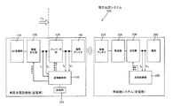
- FIG. 1 is a block diagram of a power transmission system according to an embodiment of the present invention
- FIG. 2 is a diagram schematically showing an example in which a power transmission system 100 according to an embodiment of the present invention is mounted on a vehicle.
- the power transmission system 100 of the present invention is suitable for use in a system for charging a vehicle-mounted battery such as an electric vehicle (EV) or a hybrid electric vehicle (HEV).
- a power receiving antenna 210 that enables power reception is arranged on the bottom surface of the vehicle.
- the power transmission system 100 according to the present embodiment is provided in a stop space where the vehicle can be stopped in order to transmit power to the vehicle as described above in a non-contact manner.
- the stop space which is a vehicle charging space, is configured such that the power transmission antenna 140 of the power transmission system 100 according to the present embodiment is embedded in the underground.
- the user of the vehicle stops the vehicle in the stop space where the power transmission system according to this embodiment is provided, and transmits electric energy from the power transmission antenna 140 to the power receiving antenna 210 mounted on the vehicle via an electromagnetic field. To do.
- the positional relationship between the power transmission antenna 140 and the power reception antenna 210 changes each time power transmission is performed, and the optimal power transmission efficiency is achieved.
- the rectification booster 120 in the vehicle charging facility is a converter that converts an AC voltage from the AC power supply 110 such as a commercial power source into a constant DC, and boosts the output from the converter to a predetermined voltage. is there. Setting of the voltage generated by the rectifying booster 120 can be controlled from the power transmission controller 150.
- the inverter unit 130 generates a predetermined AC voltage from the DC voltage supplied from the rectifying and boosting unit 120 and inputs the generated AC voltage to the power transmission antenna 140.
- FIG. 3 is a diagram illustrating an inverter unit of the power transmission system according to the embodiment of the present invention.
- the inverter unit 130 includes four field effect transistors (FETs) composed of Q A to Q D connected in a full bridge system.
- FETs field effect transistors
- connection portion T1 between the switching elements Q A and Q B connected in series and the connection portion T2 between the switching elements Q C and Q D connected in series When the switching element Q A and the switching element Q D are on, the switching element Q B and the switching element Q C are turned off, and the switching element Q B and the switching element Q D are connected to each other. When C is on, the switching element Q A and the switching element Q D are turned off, thereby generating a rectangular AC voltage between the connection portion T1 and the connection portion T2.
- Drive signals for the switching elements Q A to Q D constituting the inverter unit 130 as described above are input from the power transmission control unit 150.
- the frequency for driving the inverter unit 130 can be controlled from the power transmission control unit 150.
- the output from the inverter unit 130 as described above is supplied to the power transmission antenna 140.
- the power transmission antenna 140 is composed of a coil having an inductance component, which will be described later, and the electric energy output from the power transmission antenna 140 by resonating with the vehicle-mounted power reception antenna 210 disposed so as to face each other. Can be sent to the power receiving antenna 210.
- the impedance may be once matched by a matching unit (not shown).
- the matching unit can be composed of passive elements having a predetermined circuit constant.
- the resonance frequency of the power transmission antenna 140 and the power reception By making the resonance frequency of the antenna 210 the same, energy is efficiently transmitted from the power transmission side antenna to the power reception side antenna.
- the power transmission control unit 150 includes a general-purpose information processing unit including a CPU, a ROM that stores a program that operates on the CPU, and a RAM that is a work area of the CPU.
- the power transmission control unit 150 includes the acquired input power (W 1 )
- the efficiency (W 1 / W 2 ) of the inverter unit 130 is calculated from the output power (W 2 ).
- the storage unit 151 in the power transmission control unit 150 is a temporary storage unit that stores the frequency and the calculated inverter efficiency in association with each other when performing a frequency sweep.
- the power transmission control unit 150 controls the output power of the inverter unit 130 to be a predetermined power, calculates the inverter efficiency of the inverter unit 130 while changing the frequency of the AC voltage output by the inverter unit 130, This is stored in the storage unit 151.
- the power transmission control unit 150 controls the frequency of the DC voltage output from the rectification booster unit 120 and the frequency of the AC voltage output from the inverter unit 130, and executes actual charging power transmission.
- the power receiving antenna 210 receives electrical energy output from the power transmitting antenna 140 by resonating with the power transmitting antenna 140.
- the AC power received by the power receiving antenna 210 is rectified by the rectifier 2220, and the rectified power is stored in the battery 240 through the charger 2330.
- the charger 230 controls the storage of the battery 240 based on a command from the charge control unit 250.
- the battery 240 is used as a load on the power receiving side system and charging is performed on the battery 240, but other loads may be used as the load on the power receiving side system. .
- the voltage V 3 and the current I 3 input from the charger 230 to the battery 240 are measured by the charge control unit 250. Based on the measured voltage V 3 and current I 3 , the charging control unit 250 is configured to control the charger 2 30 to control charging of the battery 240 so as to follow an appropriate charging profile of the battery 240. Has been.
- the charger 230 can select whether the battery 240 is charged with a constant current, a constant output, or a constant voltage.
- the charge control unit 250 has a general-purpose information processing unit including a CPU, a ROM that holds a program that runs on the CPU, and a RAM that is a work area of the CPU, and is connected to the illustrated charge control unit 250. Operate in cooperation with each component.
- the charging control unit 250 stores a charging profile of the battery 240 and stores an algorithm for operating the charging control unit 250 along the profile.
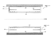
- FIG. 4 is an exploded perspective view of the power receiving antenna 210 used in the power transmission system according to the embodiment of the present invention
- FIG. 5 is a cross-sectional view showing a state of power transmission between the antennas in the power transmission according to the embodiment of the present invention.
- It is a schematic diagram.
- a rectangular flat plate is described as an example of the coil body 270, but the antenna of the present invention is not limited to such a coil.
- a circular flat plate or the like can be used as the coil body 270.
- Such a coil body 270 functions as a magnetic resonance antenna part in the power receiving antenna 210.
- This “magnetic resonance antenna section” includes not only the inductance component of the coil body 270 but also a capacitance component based on its floating capacity, or a capacitance component based on an intentionally added capacitor.
- the coil case 260 is used to accommodate the coil body 270 having the inductance component of the power receiving antenna 210.
- the coil case 260 has a box shape having an opening made of a resin such as polycarbonate. From each side of the rectangular bottom plate portion 261 of the coil case 260, a side plate portion 262 is provided so as to extend in a direction perpendicular to the bottom plate portion 261. An upper opening 263 is formed above the coil case 260 so as to be surrounded by the side plate 262.
- the power receiving antenna 210 packaged in the coil case 260 is attached to the vehicle main body on the upper opening 263 side.
- any conventionally known method can be used.
- a flange member or the like may be provided around the upper opening 263 in order to improve attachment to the vehicle main body.
- the coil body 270 includes a rectangular flat plate-like base material 271 made of glass epoxy and a spiral conductive portion 272 formed on the base material 271.
- a conductive line (not shown) is electrically connected to the first end portion 273 on the inner peripheral side and the second end portion 274 on the outer peripheral side of the conductive portion 272 having a spiral shape.
- the power received by the power receiving antenna 210 can be guided to the rectifying unit 202.
- Such a coil body 270 is placed on the rectangular bottom plate portion 261 of the coil case 260 and fixed on the bottom plate portion 261 by an appropriate fixing means.
- the magnetic shield body 280 is a flat magnetic member having a hollow portion 285.
- the specific resistance is large, the magnetic permeability is large, and the magnetic hysteresis is small.
- a magnetic material such as ferrite can be used.
- the magnetic shield body 280 is arranged with a certain amount of space above the coil body 270 by being fixed to the coil case 260 by an appropriate means. With such a layout, the lines of magnetic force generated on the power transmission antenna 105 side have a high rate of transmission through the magnetic shield body 280, and in power transmission from the power transmission antenna 105 to the power reception antenna 210, the metal lines constituting the vehicle main body portion are used. The effect on the magnetic field lines is minimal.
- a rectangular plate-shaped metal body lid 290 that covers the upper opening 263 is arranged above the shield body 280 at a predetermined distance. ing. Any material can be used as the metal material used for the metal body lid 290. In this embodiment, for example, aluminum is used.
- the vehicle main body is configured. It is possible to efficiently transmit power while suppressing the influence of metal objects.
- the structure of the power receiving antenna 210 as described above is also applied to a power transmission side antenna constituting the power transmission system 100.
- the power transmitting antenna 105 is configured to be plane-symmetric (mirror image symmetric) with respect to the power receiving antenna 210 and the horizontal plane.
- the coil body 370 is arranged in the coil case 360, the magnetic shield body 380 is provided at a predetermined distance from the coil body 360, and the coil case 160 is sealed by the metal body lid 390, similarly to the power receiving side. It is a structure that is made.
- power transmission by the power transmission system 100 according to the present embodiment configured as described above will be described.
- frequency sweep is performed with the power used in the power transmission, and the extreme value of the inverter efficiency is selected. Based on this, the frequency at which the inverter unit 130 is driven by the actual power transmission is determined.
- the optimal frequency is selected in this way, and then power transmission is performed using the selected optimal frequency.
- FIG. 6 is a diagram showing a flowchart of power transmission processing in the power transmission system according to the embodiment of the present invention. Such a flowchart is executed by the power transmission control unit 150.
- the power transmission control unit 150 sets the rectification boosting unit 120 so that the target output value becomes a predetermined power value.
- step S102 the drive frequency of the inverter unit 130 is set to a lower limit value for sweeping.
- step S103 executes the power transmission by the first power, by measuring the V 1, I 1, V 2 , I 2 in step S104, the input power (W 1), measures the output power (W 2) .
- step S106 the calculated inverter efficiency and the frequency are stored in the storage unit 151 in association with each other.
- the frequency characteristics of the inverter efficiency are accumulated in the storage unit 151.
- step S107 it is determined whether or not the set frequency is equal to or higher than the upper limit frequency to be swept. If the determination in step S107 is NO, the process proceeds to step S110, the frequency is increased and set by a predetermined amount, and then the process returns to step S103 and loops.
- step S107 determines whether the frequency that gives the extreme value of the inverter efficiency is selected from the frequency characteristics stored in the storage unit 151.
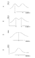
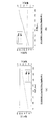
- FIG. 7 is a diagram illustrating the relationship between the frequency and the power transmission efficiency in the power transmission system according to the present embodiment.
- FIG. 7A shows frequency characteristics of power transmission efficiency corresponding to a state when the power receiving antenna 210 and the power transmitting antenna 140 are most appropriately arranged. As shown in FIG. 7A, there are two frequencies that give two extreme values. The extreme frequency with the lower frequency is defined as the first extreme frequency, and the extreme frequency with the higher frequency is defined as the second extreme frequency.
- the frequency of this extreme value can be selected in step S108. Good.
- the first extreme value frequency and the second extreme value frequency when there are two frequencies that give extreme values, the first extreme value frequency and the second extreme value frequency, in this embodiment, power transmission An extreme frequency at which an electric wall is generated on a plane of symmetry between the antenna 140 and the power receiving antenna 210 is selected.
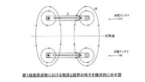
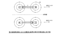
- FIG. 8 is a diagram schematically showing the current and electric field at the first extreme frequency.
- the current flowing through the power transmitting antenna 140 and the current flowing through the power receiving antenna 210 have substantially the same phase, and the position where the magnetic field vectors are aligned is near the center of the power transmitting antenna 140 or the power receiving antenna 210.
- This state is considered as a magnetic wall in which the direction of the magnetic field is perpendicular to the symmetry plane between the power transmission antenna 140 and the power reception antenna 210.
- FIG. 9 is a diagram schematically showing the state of current and electric field at the second extreme frequency.
- the phases of the current flowing through the power transmission antenna 140 and the current flowing through the power reception antenna 210 are almost opposite, and the position where the magnetic field vectors are aligned is near the symmetry plane of the power transmission antenna 140 and the power reception antenna 210.
- This state is considered as an electrical wall in which the direction of the magnetic field is horizontal with respect to the plane of symmetry between the power transmitting antenna 140 and the power receiving antenna 210.
- FIG. 10 is a diagram showing characteristics at an extreme value frequency (first frequency) at which a magnetic wall is generated, among extreme value frequencies giving two extreme values.
- FIG. 10A is a diagram showing how the voltage (V 1 ) and current (I 1 ) on the power transmission side vary with the load change fluctuation of the battery 240 (load), and FIG. receiving side of the voltage due to load change variation of the load) (V 3), it is a diagram showing a state of variation of the current (I 3). According to the characteristics shown in FIG. 10, it can be seen that there is a characteristic that the voltage increases as the load of the battery 240 (load) increases on the power receiving side.
- the power receiving antenna 210 can be seen as a constant current source when viewed from the battery 240 side.
- the power receiving antenna 210 operates like a constant current source, if an emergency stop occurs due to a malfunction of the battery 240 on the load side, both ends of the power receiving antenna 210 are The voltage will increase.
- FIG. 11 is a diagram showing characteristics at an extreme value frequency (second frequency) at which an electric wall is generated, among extreme value frequencies giving two extreme values.
- FIG. 11A is a diagram showing how the voltage (V 1 ) and current (I 1 ) on the power transmission side change with the load change fluctuation of the battery 240 (load), and FIG. receiving side of the voltage due to load change variation of the load) (V 3), it is a diagram showing a state of variation of the current (I 3). According to the characteristics shown in FIG. 11, it can be seen that there is a characteristic that the current decreases as the load of the battery 240 (load) increases on the power receiving side.
- the power receiving antenna 210 can be seen as a constant voltage source when viewed from the battery 240 side.
- the power receiving antenna 210 operates as a constant voltage source, even if an emergency stop occurs due to a malfunction of the battery 240 on the load side, both ends of the power receiving antenna 210
- the voltage of the part does not increase. Therefore, according to the power transmission system of the present invention, when the load is suddenly reduced, the voltage does not become high voltage, and it is possible to perform power transmission stably.
- the charging circuit appears as a current source for the battery 240 (load) on the power receiving side, and the charging circuit is a voltage for the battery 240 (load) on the power receiving side in the characteristics of FIG. It will appear as a source.
- the characteristics shown in FIG. 11 in which the current decreases as the load increases are preferable for the battery 240 (load).
- the first extreme frequency and the second extreme frequency of 2 are used. In the case where there is one, an extreme frequency at which an electric wall is generated on the plane of symmetry between the power transmitting antenna 140 and the power receiving antenna 210 is selected.
- the optimum frequency at the time of power transmission can be determined. Power transmission can be performed.
- the battery 240 (load) is charged. Since the circuit appears as a voltage source, there is an advantage that it is easy to handle because the output of the inverter unit 130 increases and decreases when the output to the battery 240 fluctuates due to charge control. Moreover, since the power supply is automatically minimized when the charger 230 is urgently stopped, no useless device is required.
- the rectifier 220 is viewed from the charger 230. Since it appears as a voltage source, when the output to the battery 240 fluctuates due to charge control, there is an advantage that it is easy to handle because it increases and decreases with the output of the rectifying booster 120. Moreover, since the power supply is automatically minimized when the charger 230 is urgently stopped, no useless device is required.
- the charger 230 when there are two frequencies that give two extreme values, the charger 230 outputs the extreme frequency when a magnetic wall is generated on the plane of symmetry between the power transmitting antenna 140 and the power receiving antenna 210. Therefore, it is necessary to control the supply voltage as the value is reduced, and a communication means and a detection means for that purpose are required, which increases costs.
- step S109 power transmission is executed using the optimum frequency selected in step S108.
- the optimum frequency at the time of power transmission can be determined. Transmission can be performed.
- the power transmission system of the present invention is suitable for use in a system for charging a vehicle such as an electric vehicle (EV) or a hybrid electric vehicle (HEV) that is rapidly spreading in recent years.
- a power transmission system there are frequencies at which the receiving antenna operates as a constant current source and frequencies that operate as a constant voltage source near the frequency that gives the extreme value of transmission efficiency, but when a frequency that operates as a constant current source is used.
- the voltage at the end of the receiving antenna sometimes becomes high.
- the power transmission system according to the present invention by selecting the frequency at which the receiving antenna appears as a constant voltage source and performing power transmission, the voltage does not become high when the load is suddenly reduced. Since power transmission can be performed stably, the industrial applicability is very large.
Landscapes
- Engineering & Computer Science (AREA)
- Power Engineering (AREA)
- Mechanical Engineering (AREA)
- Transportation (AREA)
- Computer Networks & Wireless Communication (AREA)
- Life Sciences & Earth Sciences (AREA)
- Sustainable Development (AREA)
- Sustainable Energy (AREA)
- Physics & Mathematics (AREA)
- Electromagnetism (AREA)
- Electric Propulsion And Braking For Vehicles (AREA)
- Charge And Discharge Circuits For Batteries Or The Like (AREA)
- Current-Collector Devices For Electrically Propelled Vehicles (AREA)
- Secondary Cells (AREA)
Abstract
[Problem] To provide a power transmission system capable of determining a suitable frequency during power transmission and performing an efficient power transmission.
[Solution] A power transmission system according to the present invention includes an inverter unit (130) which converts a DC voltage to an AC voltage having a given frequency and outputs the converted AC voltage, a transmission antenna (140) into which the AC voltage from said inverter unit (130) is input, and a transmission control unit (150) which controls the frequency of the AC voltage output from said inverter unit (130), and said transmission antenna (140) transmits electric energy to an opposing receiving antenna via an electromagnetic field, wherein said transmission control unit (150) controls the power transmission such that the power transmission is performed with a frequency selected so that the antenna unit is seen as a constant-voltage source when viewed from a load side.
Description
本発明は、磁気共鳴方式の磁気共鳴アンテナが用いられるワイヤレス電力伝送システムに関する。
The present invention relates to a wireless power transmission system in which a magnetic resonance type magnetic resonance antenna is used.
近年、電源コードなどを用いることなく、ワイヤレスで電力(電気エネルギー)を伝送する技術の開発が盛んとなっている。ワイヤレスで電力を伝送する方式の中でも、特に注目されている技術として、磁気共鳴方式と呼ばれるものがある。この磁気共鳴方式は2007年にマサチューセッツ工科大学の研究グループが提案したものであり、これに関連する技術は、例えば、特許文献1(特表2009-501510号公報)に開示されている。
In recent years, development of technology for transmitting electric power (electric energy) wirelessly without using a power cord or the like has become active. Among wireless transmission methods, there is a technique called magnetic resonance as a technology that has attracted particular attention. This magnetic resonance method was proposed by a research group of Massachusetts Institute of Technology in 2007, and a technology related to this is disclosed in, for example, Japanese Patent Application Laid-Open No. 2009-501510.
磁気共鳴方式のワイヤレス電力伝送システムは、送電側アンテナの共振周波数と、受電側アンテナの共振周波数とを同一とすることで、送電側アンテナから受電側アンテナに対し、効率的にエネルギー伝達を行うものであり、電力伝送距離を数十cm~数mとすることが可能であることが大きな特徴の一つである。
A magnetic resonance wireless power transmission system efficiently transmits energy from a power transmission side antenna to a power reception side antenna by making the resonance frequency of the power transmission side antenna and the resonance frequency of the power reception side antenna the same. One of the major features is that the power transmission distance can be several tens of centimeters to several meters.
上記のような磁気共鳴方式のワイヤレス電力伝送システムにおいて、例えば、一方のアンテナが電気自動車のような移動体に搭載される場合には、電力伝送を行うたびに、アンテナ間の配置が変化するので、最適な電力伝送効率を与える周波数がこれに伴い変化することとなる。そこで、電力伝送を行う前段に、周波数をスイープして、本番の電力伝送時の最適周波数を決定する技術が提案されている。例えば、特許文献1(特開2010-68657号公報)に、所定周波数の交流電力を出力する交流電力出力手段と、第1共鳴コイル、及び該第1共鳴コイルと対向配置された第2共鳴コイルとを有し、前記交流電力出力手段より出力される交流電力を前記第1共鳴コイルに出力し、共鳴現象により非接触で前記交流電力を前記第2共鳴コイルに送信するワイヤレス電力送信装置において、前記第1共鳴コイルの共鳴周波数、及び前記第2共鳴コイルの共鳴周波数をそれぞれ測定し、前記交流電力出力手段より出力する交流電力の周波数を、前記各共鳴周波数の中間周波数に設定する周波数設定手段を備えることを特徴とするワイヤレス電力送信装置が開示されている。
特表2009-501510号公報
特開2010-68657号公報
In the magnetic resonance type wireless power transmission system as described above, for example, when one antenna is mounted on a moving body such as an electric vehicle, the arrangement between the antennas changes every time power is transmitted. Accordingly, the frequency that gives the optimum power transmission efficiency changes accordingly. Therefore, a technique has been proposed in which the frequency is swept before the power transmission to determine the optimum frequency during actual power transmission. For example, in Patent Document 1 (Japanese Patent Laid-Open No. 2010-68657), AC power output means for outputting AC power of a predetermined frequency, a first resonance coil, and a second resonance coil arranged to face the first resonance coil In the wireless power transmission device that outputs the AC power output from the AC power output means to the first resonance coil, and transmits the AC power to the second resonance coil in a non-contact manner due to a resonance phenomenon, Frequency setting means for measuring the resonance frequency of the first resonance coil and the resonance frequency of the second resonance coil, respectively, and setting the frequency of the AC power output from the AC power output means as an intermediate frequency of the resonance frequencies. There is disclosed a wireless power transmission apparatus comprising:
Special table 2009-501510 JP 2010-68657 A
ところで、伝送効率の極値を与える周波数付近において、受信アンテナが定電流源に動作する周波数と定電圧源として動作する周波数が存在している。定電流源として動作する周波数を使用した場合、負荷側の理由により緊急停止が起きた場合に受信アンテナ端部の電圧が高圧になってしまう問題があった。
By the way, in the vicinity of a frequency that gives an extreme value of transmission efficiency, there are a frequency at which the receiving antenna operates as a constant current source and a frequency at which it operates as a constant voltage source. When a frequency operating as a constant current source is used, there is a problem that the voltage at the end of the receiving antenna becomes high when an emergency stop occurs due to a load side reason.
上記問題を解決するために、請求項1に係る発明は、直流電圧を所定の周波数の交流電圧に変換して出力するインバータ部と、前記インバータ部からの交流電圧が入力される送電アンテナと、前記インバータ部によって出力される交流電圧の周波数を制御する制御部と、を有し、前記送電アンテナから対向する受電アンテナ210に対して、電磁場を介して電気エネルギーを伝送する電力伝送システムであって、前記制御部は、負荷側からみてアンテナ部が定電圧源として見える周波数を選定して電力伝送を行うように制御することを特徴とする。
In order to solve the above problem, the invention according to claim 1 is an inverter unit that converts a DC voltage into an AC voltage having a predetermined frequency and outputs the AC voltage, a power transmission antenna that receives the AC voltage from the inverter unit, And a control unit that controls the frequency of the AC voltage output by the inverter unit, the power transmission system transmitting electrical energy to the power receiving antenna 210 facing the power transmitting antenna via an electromagnetic field. The control unit controls the power transmission by selecting a frequency at which the antenna unit can be seen as a constant voltage source when viewed from the load side.
本発明に係る電力伝送システムによれば、負荷が急激に低下した際に電圧が高圧になることがなく、安定して電力伝送を行うことが可能となる。
According to the power transmission system of the present invention, the voltage does not become high when the load is suddenly reduced, and it is possible to perform power transmission stably.
以下、本発明の実施形態を図面を参照しつつ説明する。図1は本発明の実施形態に係る電力伝送システムのブロック図であり、図2は本発明の実施形態に係る電力伝送システム100を車両に搭載した例を模式的に示す図である。本発明の電力伝送システム100は、例えば、電気自動車(EV)やハイブリッド電気自動車(HEV)などの車両搭載電池への充電のためのシステムに用いるのに好適である。このために、車両の底面部においては、受電を行うことを可能にする受電アンテナ210が配されてなる。
Hereinafter, embodiments of the present invention will be described with reference to the drawings. FIG. 1 is a block diagram of a power transmission system according to an embodiment of the present invention, and FIG. 2 is a diagram schematically showing an example in which a power transmission system 100 according to an embodiment of the present invention is mounted on a vehicle. The power transmission system 100 of the present invention is suitable for use in a system for charging a vehicle-mounted battery such as an electric vehicle (EV) or a hybrid electric vehicle (HEV). For this reason, a power receiving antenna 210 that enables power reception is arranged on the bottom surface of the vehicle.
本実施形態に係る電力伝送システム100では、上記のような車両に対して電力を非接触で伝送するため、当該車両を停車させることが可能な停車スペースに設けられる。車両充電用のスペースである当該停車スペースには、本実施形態に係る電力伝送システム100の送電アンテナ140などが地中部に埋設されるような構成となっている。車両のユーザーは本実施形態に係る電力伝送システムが設けられている停車スペースに車両を停車させて、送電アンテナ140から車両に搭載されている受電アンテナ210に対して、電磁場を介し電気エネルギーを伝送する。
The power transmission system 100 according to the present embodiment is provided in a stop space where the vehicle can be stopped in order to transmit power to the vehicle as described above in a non-contact manner. The stop space, which is a vehicle charging space, is configured such that the power transmission antenna 140 of the power transmission system 100 according to the present embodiment is embedded in the underground. The user of the vehicle stops the vehicle in the stop space where the power transmission system according to this embodiment is provided, and transmits electric energy from the power transmission antenna 140 to the power receiving antenna 210 mounted on the vehicle via an electromagnetic field. To do.
本実施形態に係る電力伝送システム100は、上記のような利用形態であることから、送電アンテナ140と受電アンテナ210との間の位置関係が電力伝送を行うたびに変化し、最適な電力伝送効率を与える周波数についてもこれに伴い変化することとなる。そこで、車両停車後、すなわち、送電アンテナ140と受電アンテナ210と間の位置関係がフィックスした後、実際の充電の電力伝送を行う前段に、周波数をスイープして、電力伝送時の最適周波数を決定するようにしている。
Since the power transmission system 100 according to the present embodiment is in the above usage pattern, the positional relationship between the power transmission antenna 140 and the power reception antenna 210 changes each time power transmission is performed, and the optimal power transmission efficiency is achieved. As a result, the frequency that gives rises to change. Therefore, after the vehicle stops, that is, after the positional relationship between the power transmitting antenna 140 and the power receiving antenna 210 is fixed, the frequency is swept to determine the optimum frequency for power transmission before the actual power transmission for charging. Like to do.
車両充電設備(送電側)における整流昇圧部120は、商用電源などのAC電源部110からの交流電圧を一定の直流に変換するコンバータと、このコンバータからの出力を所定の電圧に昇圧するものである。この整流昇圧部120で生成される電圧の設定は送電制御部150から制御可能となっている。
The rectification booster 120 in the vehicle charging facility (on the power transmission side) is a converter that converts an AC voltage from the AC power supply 110 such as a commercial power source into a constant DC, and boosts the output from the converter to a predetermined voltage. is there. Setting of the voltage generated by the rectifying booster 120 can be controlled from the power transmission controller 150.
インバータ部130は、整流昇圧部120から供給される直流電圧から所定の交流電圧を生成して、送電アンテナ140に入力する。図3は本発明の実施形態に係る電力伝送システムのインバータ部を示す図である。インバータ部130は、例えば図3に示すように、フルブリッジ方式で接続されたQA乃至QDからなる4つの電界効果トランジスタ(FET)によって構成されている。
The inverter unit 130 generates a predetermined AC voltage from the DC voltage supplied from the rectifying and boosting unit 120 and inputs the generated AC voltage to the power transmission antenna 140. FIG. 3 is a diagram illustrating an inverter unit of the power transmission system according to the embodiment of the present invention. For example, as shown in FIG. 3, the inverter unit 130 includes four field effect transistors (FETs) composed of Q A to Q D connected in a full bridge system.
本実施形態においては、直列接続されたスイッチング素子QAとスイッチング素子QBの間の接続部T1と、直列接続されたスイッチング素子QCとスイッチング素子QDとの間の接続部T2との間に送電アンテナ140が接続される構成となっており、スイッチング素子QAとスイッチング素子QDがオンのとき、スイッチング素子QBとスイッチング素子QCがオフとされ、スイッチング素子QBとスイッチング素子QCがオンのとき、スイッチング素子QAとスイッチング素子QDがオフとされることで、接続部T1と接続部T2との間に矩形波の交流電圧を発生させる。
In the present embodiment, between the connection portion T1 between the switching elements Q A and Q B connected in series and the connection portion T2 between the switching elements Q C and Q D connected in series. When the switching element Q A and the switching element Q D are on, the switching element Q B and the switching element Q C are turned off, and the switching element Q B and the switching element Q D are connected to each other. When C is on, the switching element Q A and the switching element Q D are turned off, thereby generating a rectangular AC voltage between the connection portion T1 and the connection portion T2.
上記のようなインバータ部130を構成するスイッチング素子QA乃至QDに対する駆動信号は送電制御部150から入力されるようになっている。また、インバータ部130を駆動させるための周波数は送電制御部150から制御することができるようになっている。
Drive signals for the switching elements Q A to Q D constituting the inverter unit 130 as described above are input from the power transmission control unit 150. The frequency for driving the inverter unit 130 can be controlled from the power transmission control unit 150.
上記のようなインバータ部130からの出力は送電アンテナ140に供給される。この送電アンテナ140は、インダクタンス成分を有する後述するようなコイルから構成されており、対向するようにして配置される車両搭載の受電アンテナ210と共鳴することで、送電アンテナ140から出力される電気エネルギーを受電アンテナ210に送ることができるようになっている。
The output from the inverter unit 130 as described above is supplied to the power transmission antenna 140. The power transmission antenna 140 is composed of a coil having an inductance component, which will be described later, and the electric energy output from the power transmission antenna 140 by resonating with the vehicle-mounted power reception antenna 210 disposed so as to face each other. Can be sent to the power receiving antenna 210.
なお、インバータ部130からの出力を、送電アンテナ140に入力する際には、いったん、不図示の整合器によってインピーダンスを整合させるようにしてもよい。整合器は所定の回路定数を有する受動素子から構成することができる。
Note that when the output from the inverter unit 130 is input to the power transmission antenna 140, the impedance may be once matched by a matching unit (not shown). The matching unit can be composed of passive elements having a predetermined circuit constant.
本発明の実施形態に係る電力伝送システムでは、電力伝送システム100の送電側の送電アンテナ140から、受電側の受電アンテナ210へ効率的に電力を伝送する際、送電アンテナ140の共振周波数と、受電アンテナ210の共振周波数とを同一とすることで、送電側アンテナから受電側アンテナに対し、効率的にエネルギー伝達を行うようにしている。
In the power transmission system according to the embodiment of the present invention, when power is efficiently transmitted from the power transmission antenna 140 on the power transmission side of the power transmission system 100 to the power reception antenna 210 on the power reception side, the resonance frequency of the power transmission antenna 140 and the power reception By making the resonance frequency of the antenna 210 the same, energy is efficiently transmitted from the power transmission side antenna to the power reception side antenna.
インバータ部130に対する入力される電圧V1及び電流I1、インバータ部130から出力される電圧V2及び電流I2は送電制御部150によって計測されるようになっている。これにより、送電制御部150は、計測される電圧V1及び電流I1からインバータ部130に入力される入力電力(W1=V1×I1)、及び、計測される電圧V2及び電流I2からインバータ部130から出力される出力電力(W2=V2×I2)を取得することができるようになっている。送電制御部150は、CPUとCPU上で動作するプログラムを保持するROMとCPUのワークエリアであるRAMなどからなる汎用の情報処理部を有しており、取得された入力電力(W1)と出力電力(W2)とからインバータ部130の効率(W1/W2)を演算する。
The power transmission control unit 150 measures the voltage V 1 and current I 1 input to the inverter unit 130 and the voltage V 2 and current I 2 output from the inverter unit 130. Thereby, the power transmission control unit 150 inputs the input power (W 1 = V 1 × I 1 ) input to the inverter unit 130 from the measured voltage V 1 and current I 1 , and the measured voltage V 2 and current. and it is capable of obtaining the output power from the I 2 output from the inverter unit 130 (W 2 = V 2 × I 2). The power transmission control unit 150 includes a general-purpose information processing unit including a CPU, a ROM that stores a program that operates on the CPU, and a RAM that is a work area of the CPU. The power transmission control unit 150 includes the acquired input power (W 1 ) The efficiency (W 1 / W 2 ) of the inverter unit 130 is calculated from the output power (W 2 ).
送電制御部150における記憶部151は、周波数スイープを行うときに、周波数と演算されたインバータ効率とを対応付けて記憶する一時記憶手段である。送電制御部150は、インバータ部130の出力電力が所定の電力となるように制御し、インバータ部130で出力する交流電圧の周波数を変更しつつ、インバータ部130のインバータ効率を演算していき、この記憶部151に記憶する。
The storage unit 151 in the power transmission control unit 150 is a temporary storage unit that stores the frequency and the calculated inverter efficiency in association with each other when performing a frequency sweep. The power transmission control unit 150 controls the output power of the inverter unit 130 to be a predetermined power, calculates the inverter efficiency of the inverter unit 130 while changing the frequency of the AC voltage output by the inverter unit 130, This is stored in the storage unit 151.
送電制御部150は、整流昇圧部120によって出力される直流電圧の電圧と、インバータ部130で出力される交流電圧の周波数を制御して、実際の充電の電力伝送を実行する。
The power transmission control unit 150 controls the frequency of the DC voltage output from the rectification booster unit 120 and the frequency of the AC voltage output from the inverter unit 130, and executes actual charging power transmission.
次に、車両側に設けられている電力伝送システム100の構成について説明する。車両の受電側のシステムにおいて、受電アンテナ210は、送電アンテナ140と共鳴することによって、送電アンテナ140から出力される電気エネルギーを受電するものである。
Next, the configuration of the power transmission system 100 provided on the vehicle side will be described. In the system on the power receiving side of the vehicle, the power receiving antenna 210 receives electrical energy output from the power transmitting antenna 140 by resonating with the power transmitting antenna 140.
受電アンテナ210で受電された交流電力は、整流器220において整流され、整流された電力は充電器230を通して電池240に蓄電されるようになっている。充電器230は充電制御部250からの指令に基づいて電池240の蓄電を制御する。なお、本実施形態においては、受電側システムの負荷として電池240を用い、これに充電を行う例について説明しているが、受電側システムの負荷としては、その他の負荷を用いるようにしてもよい。
The AC power received by the power receiving antenna 210 is rectified by the rectifier 2220, and the rectified power is stored in the battery 240 through the charger 2330. The charger 230 controls the storage of the battery 240 based on a command from the charge control unit 250. In the present embodiment, an example is described in which the battery 240 is used as a load on the power receiving side system and charging is performed on the battery 240, but other loads may be used as the load on the power receiving side system. .
充電器230から電池240に対して入力される電圧V3及び電流I3は充電制御部250によって計測されるようになっている。計測された電圧V3及び電流I3により、充電制御部250は、充電器230を制御して、電池240の適切な充電プロファイルに沿うように電池240の充電を制御することができるように構成されている。充電器230は、電池240を定電流、定出力、定電圧のいずれかで充電させるかを選択することができるようになっている。
The voltage V 3 and the current I 3 input from the charger 230 to the battery 240 are measured by the charge control unit 250. Based on the measured voltage V 3 and current I 3 , the charging control unit 250 is configured to control the charger 2 30 to control charging of the battery 240 so as to follow an appropriate charging profile of the battery 240. Has been. The charger 230 can select whether the battery 240 is charged with a constant current, a constant output, or a constant voltage.
充電制御部250はCPUとCPU上で動作するプログラムを保持するROMとCPUのワークエリアであるRAMなどからなる汎用の情報処理部を有しており、図示されている充電制御部250と接続される各構成と協働するように動作する。
The charge control unit 250 has a general-purpose information processing unit including a CPU, a ROM that holds a program that runs on the CPU, and a RAM that is a work area of the CPU, and is connected to the illustrated charge control unit 250. Operate in cooperation with each component.
充電制御部250は 電池240の充電プロファイルを記憶すると共に、充電制御部250をこのプロファイルに沿って動作させるためのアルゴリズムを記憶している。
The charging control unit 250 stores a charging profile of the battery 240 and stores an algorithm for operating the charging control unit 250 along the profile.
図4は本発明の実施形態に係る電力伝送システムに用いられる受電アンテナ210の分解斜視図であり、図5は本発明の実施形態に係る電力伝送におけるアンテナ間の電力伝送の様子を示す断面の模式図である。なお、以下の実施形態では、コイル体270として矩形平板状のものを例に説明するが、本発明のアンテナはこのような形状のコイルに限定されるものではない。例えば、コイル体270として円形平板状のものなども利用し得る。このようなコイル体270は、受電アンテナ210における磁気共鳴アンテナ部として機能する。この「磁気共鳴アンテナ部」は、コイル体270のインダクタンス成分のみならず、その浮游容量に基づくキャパシタンス成分、或いは意図的に追加したコンデンサに基づくキャパシタンス成分をも含むものである。
4 is an exploded perspective view of the power receiving antenna 210 used in the power transmission system according to the embodiment of the present invention, and FIG. 5 is a cross-sectional view showing a state of power transmission between the antennas in the power transmission according to the embodiment of the present invention. It is a schematic diagram. In the following embodiments, a rectangular flat plate is described as an example of the coil body 270, but the antenna of the present invention is not limited to such a coil. For example, a circular flat plate or the like can be used as the coil body 270. Such a coil body 270 functions as a magnetic resonance antenna part in the power receiving antenna 210. This “magnetic resonance antenna section” includes not only the inductance component of the coil body 270 but also a capacitance component based on its floating capacity, or a capacitance component based on an intentionally added capacitor.
コイルケース260は、受電アンテナ210のインダクタンス成分を有するコイル体270を収容するために用いられるものである。このコイルケース260は、例えばポリカーボネートなどの樹脂により構成される開口を有する箱体の形状をなしている。コイルケース260の矩形状の底板部261の各辺からは側板部262が、前記底板部261に対して垂直方向に延在するようにして設けられている。そして、コイルケース260の上方においては、側板部262に囲まれるような上方開口部263が構成されている。コイルケース260にパッケージされた受電アンテナ210はこの上方開口部263側で車両本体部に取り付けられる。コイルケース260を車両本体部に取り付けるためには、従来周知の任意の方法を用いることができる。なお、上方開口部263の周囲には、車両本体部への取り付け性を向上するために、フランジ部材などを設けるようにしても良い。
The coil case 260 is used to accommodate the coil body 270 having the inductance component of the power receiving antenna 210. The coil case 260 has a box shape having an opening made of a resin such as polycarbonate. From each side of the rectangular bottom plate portion 261 of the coil case 260, a side plate portion 262 is provided so as to extend in a direction perpendicular to the bottom plate portion 261. An upper opening 263 is formed above the coil case 260 so as to be surrounded by the side plate 262. The power receiving antenna 210 packaged in the coil case 260 is attached to the vehicle main body on the upper opening 263 side. In order to attach the coil case 260 to the vehicle main body, any conventionally known method can be used. A flange member or the like may be provided around the upper opening 263 in order to improve attachment to the vehicle main body.
コイル体270は、ガラスエポキシ製の矩形平板状の基材271と、この基材271上に形成される渦巻き状の導電部272とから構成されている。渦巻き状をなす導電部272の内周側の第1端部273、及び外周側の第2端部274には導電線路(不図示)が電気接続される。これにより、受電アンテナ210によって受電した電力を整流部202へと導けるようになっている。このようなコイル体270はコイルケース260の矩形状の底板部261上に載置され、適当な固着手段によって底板部261上に固着される。
The coil body 270 includes a rectangular flat plate-like base material 271 made of glass epoxy and a spiral conductive portion 272 formed on the base material 271. A conductive line (not shown) is electrically connected to the first end portion 273 on the inner peripheral side and the second end portion 274 on the outer peripheral side of the conductive portion 272 having a spiral shape. As a result, the power received by the power receiving antenna 210 can be guided to the rectifying unit 202. Such a coil body 270 is placed on the rectangular bottom plate portion 261 of the coil case 260 and fixed on the bottom plate portion 261 by an appropriate fixing means.
磁性シールド体280は、中抜き部285を有する平板状の磁性部材である。この磁性シールド体280を構成するためには、比抵抗が大きく、透磁率が大きく、磁気ヒステリシスが小さいものが望ましく、例えばフェライトなどの磁性材料を用いることができる。磁性シールド体280は、コイルケース260に対して適当な手段により固着されることで、コイル体270の上方にある程度の空間を空けて配されるようになっている。このようなレイアウトにより、送電アンテナ105側で発生する磁力線は、磁性シールド体280を透過する率が高くなり、送電アンテナ105から受電アンテナ210への電力伝送において、車両本体部を構成する金属物による磁力線への影響が軽微となる。
The magnetic shield body 280 is a flat magnetic member having a hollow portion 285. In order to configure the magnetic shield body 280, it is desirable that the specific resistance is large, the magnetic permeability is large, and the magnetic hysteresis is small. For example, a magnetic material such as ferrite can be used. The magnetic shield body 280 is arranged with a certain amount of space above the coil body 270 by being fixed to the coil case 260 by an appropriate means. With such a layout, the lines of magnetic force generated on the power transmission antenna 105 side have a high rate of transmission through the magnetic shield body 280, and in power transmission from the power transmission antenna 105 to the power reception antenna 210, the metal lines constituting the vehicle main body portion are used. The effect on the magnetic field lines is minimal.
また、コイルケース260の上方開口部263においては、前記上方開口部263を覆うような矩形平板状の金属体蓋部290が、シールド体280の上方に所定距離をおいて配されるようになっている。このような金属体蓋部290に用いる金属材料として任意のものを用いることとができるが、本実施形態においては、例えばアルミニウムを用いている。
In addition, in the upper opening 263 of the coil case 260, a rectangular plate-shaped metal body lid 290 that covers the upper opening 263 is arranged above the shield body 280 at a predetermined distance. ing. Any material can be used as the metal material used for the metal body lid 290. In this embodiment, for example, aluminum is used.
以上のように、本発明の受電アンテナ210によれば、コイル体270の上方に磁性シールド体280が設けられているので、車両底面に受電アンテナ210を装着した場合でも、車両本体部を構成する金属物などの影響を抑制して、効率的に電力伝送を行うことが可能となる。
As described above, according to the power receiving antenna 210 of the present invention, since the magnetic shield body 280 is provided above the coil body 270, even when the power receiving antenna 210 is mounted on the bottom surface of the vehicle, the vehicle main body is configured. It is possible to efficiently transmit power while suppressing the influence of metal objects.
また、上記のような受電アンテナ210の構造は、電力伝送システム100を構成する送電側のアンテナにも適用されている。この場合、図5に示すように、送電アンテナ105は、受電アンテナ210と水平面に対して面対称(鏡像対称)となるような構造とされている。
Further, the structure of the power receiving antenna 210 as described above is also applied to a power transmission side antenna constituting the power transmission system 100. In this case, as shown in FIG. 5, the power transmitting antenna 105 is configured to be plane-symmetric (mirror image symmetric) with respect to the power receiving antenna 210 and the horizontal plane.
送電アンテナ140においても、受電側同様に、コイル体370がコイルケース360に配され、これと所定距離離されて磁性シールド体380が設けられると共に、金属体蓋部390によってコイルケース160が封止されてなる構造である。
Also in the power transmission antenna 140, the coil body 370 is arranged in the coil case 360, the magnetic shield body 380 is provided at a predetermined distance from the coil body 360, and the coil case 160 is sealed by the metal body lid 390, similarly to the power receiving side. It is a structure that is made.
次に、以上のように構成される本実施形態に係る電力伝送システム100による電力伝送について説明する。これまで説明したように、電力伝送システム100による電力伝送では、まず、実際の充電の前段階において、電力伝送で用いられる電力で周波数スイープを行い、インバータ効率の極値を選定して、これに基づいて、本番の電力伝送でインバータ部130を駆動する周波数を決定する。本実施形態に係る電力伝送システム100による電力伝送では、まず、このように最適周波数を選定し、その後、選定された最適周波数によって電力伝送を行う。
Next, power transmission by the power transmission system 100 according to the present embodiment configured as described above will be described. As described above, in the power transmission by the power transmission system 100, first, in the stage before actual charging, frequency sweep is performed with the power used in the power transmission, and the extreme value of the inverter efficiency is selected. Based on this, the frequency at which the inverter unit 130 is driven by the actual power transmission is determined. In power transmission by the power transmission system 100 according to the present embodiment, first, the optimal frequency is selected in this way, and then power transmission is performed using the selected optimal frequency.
図6は本発明の実施形態に係る電力伝送システムにおける電力伝送処理のフローチャートを示す図である。このようなフローチャートは送電制御部150によって実行される。図6において、ステップS100で電力伝送処理が開始されると、続く、ステップS101では、送電制御部150は目標出力値が所定の電力値となるように整流昇圧部120を設定する。
FIG. 6 is a diagram showing a flowchart of power transmission processing in the power transmission system according to the embodiment of the present invention. Such a flowchart is executed by the power transmission control unit 150. In FIG. 6, when the power transmission process is started in step S100, in step S101, the power transmission control unit 150 sets the rectification boosting unit 120 so that the target output value becomes a predetermined power value.
また、ステップS102においては、インバータ部130の駆動周波数をスイープする下限の値に設定する。
In step S102, the drive frequency of the inverter unit 130 is set to a lower limit value for sweeping.
ステップS103では、第1電力で電力伝送を実行し、ステップS104でV1、I1、V2、I2を計測することで、入力電力(W1)、出力電力(W2)を計測する。ステップS105では、入力電力(W1)、出力電力(W2)に基づいて、インバータ部130の効率η(=W1/W2)を演算する。
In step S103, executes the power transmission by the first power, by measuring the V 1, I 1, V 2 , I 2 in step S104, the input power (W 1), measures the output power (W 2) . In step S105, the efficiency η (= W 1 / W 2 ) of the inverter unit 130 is calculated based on the input power (W 1 ) and the output power (W 2 ).
ステップS106では、演算されたインバータ効率と、周波数とを対応させて記憶部151に記憶する。周波数を変更しつつ、インバータ効率を演算することで、この記憶部151には、インバータ効率の周波数特性が蓄積されることとなる。
In step S106, the calculated inverter efficiency and the frequency are stored in the storage unit 151 in association with each other. By calculating the inverter efficiency while changing the frequency, the frequency characteristics of the inverter efficiency are accumulated in the storage unit 151.
ステップS107では設定された周波数が、スイープする上限の周波数以上であるか否かが判定される。ステップS107の判定がNOであれば、ステップS110に進み、周波数を所定分上昇させ設定した上で、ステップS103に戻りループする。
In step S107, it is determined whether or not the set frequency is equal to or higher than the upper limit frequency to be swept. If the determination in step S107 is NO, the process proceeds to step S110, the frequency is increased and set by a predetermined amount, and then the process returns to step S103 and loops.
一方、ステップS107の判定がYESであれば全てのスイープを行ったことになるので、ステップS108に進み、記憶部151に記憶されている周波数特性からインバータ効率の極値を与える周波数を選定する。
On the other hand, if the determination in step S107 is YES, all sweeps have been performed, so the process proceeds to step S108, and the frequency that gives the extreme value of the inverter efficiency is selected from the frequency characteristics stored in the storage unit 151.
ここで、電力伝送効率の周波数特性におけるパターンについて説明する。図7は本実施形態に係る電力伝送システムにおける周波数と電力伝送効率との関係を示す図である。
Here, the pattern in the frequency characteristic of power transmission efficiency will be described. FIG. 7 is a diagram illustrating the relationship between the frequency and the power transmission efficiency in the power transmission system according to the present embodiment.
図7(A)は受電アンテナ210と送電アンテナ140とが最も適切に配置されているときの状態に対応する電力伝送効率の周波数特性を示している。図7(A)に示すように、2つの極値を与える周波数が2つある。周波数が低い方の極値周波数を第1極値周波数、周波数が高い方の極値周波数を第2極値周波数として定義する。
FIG. 7A shows frequency characteristics of power transmission efficiency corresponding to a state when the power receiving antenna 210 and the power transmitting antenna 140 are most appropriately arranged. As shown in FIG. 7A, there are two frequencies that give two extreme values. The extreme frequency with the lower frequency is defined as the first extreme frequency, and the extreme frequency with the higher frequency is defined as the second extreme frequency.
図7(A)から図7(B)、図7(C)、図7(D)と進むにつれて、受電アンテナ210と送電アンテナ140と間の位置のずれがより大きくなっているときの状態に対応する電力伝送効率の周波数特性を示している。
7A to 7B, 7C, and 7D, the position shift between the power receiving antenna 210 and the power transmitting antenna 140 becomes larger. The frequency characteristics of the corresponding power transmission efficiency are shown.
図7(C)、図7(D)に示すように、伝送効率の極値を与える周波数が1つである場合には、ステップS108においては、この極値の周波数を選定するようにすればよい。一方、図7(A)、図7(B)に示すように極値を与える周波数として、第1極値周波数、第2極値周波数の2つがある場合については、本実施形態においては、送電アンテナ140と受電アンテナ210との間の対称面に電気壁が生じる極値周波数を選定するようにしている。
As shown in FIGS. 7C and 7D, when there is one frequency that gives the extreme value of the transmission efficiency, the frequency of this extreme value can be selected in step S108. Good. On the other hand, as shown in FIGS. 7 (A) and 7 (B), when there are two frequencies that give extreme values, the first extreme value frequency and the second extreme value frequency, in this embodiment, power transmission An extreme frequency at which an electric wall is generated on a plane of symmetry between the antenna 140 and the power receiving antenna 210 is selected.
以下、送電アンテナ140と受電アンテナ210との間の対称面に生じる電気壁、及び磁気壁の概念について説明する。
Hereinafter, the concept of an electric wall and a magnetic wall generated on the symmetry plane between the power transmitting antenna 140 and the power receiving antenna 210 will be described.
図8は第1極値周波数における電流と電界の様子を模式的に示す図である。第1極値周波数においては、送電アンテナ140に流れる電流と、受電アンテナ210に流れる電流とで位相が略等しくなり、磁界ベクトルが揃う位置が送電アンテナ140や受電アンテナ210の中央部付近となる。この状態を、送電アンテナ140と受電アンテナ210との間の対称面に対して磁界の向きが垂直となる磁気壁が生じているものとして考える。
FIG. 8 is a diagram schematically showing the current and electric field at the first extreme frequency. At the first extreme value frequency, the current flowing through the power transmitting antenna 140 and the current flowing through the power receiving antenna 210 have substantially the same phase, and the position where the magnetic field vectors are aligned is near the center of the power transmitting antenna 140 or the power receiving antenna 210. This state is considered as a magnetic wall in which the direction of the magnetic field is perpendicular to the symmetry plane between the power transmission antenna 140 and the power reception antenna 210.
また、図9は第2極値周波数における電流と電界の様子を模式的に示す図である。第2極値周波数においては、送電アンテナ140に流れる電流と、受電アンテナ210に流れる電流とで位相がほぼ逆となり、磁界ベクトルが揃う位置が送電アンテナ140や受電アンテナ210の対称面付近となる。この状態を、送電アンテナ140と受電アンテナ210との間の対称面に対して磁界の向きが水平となる電気壁が生じているものとして考える。
FIG. 9 is a diagram schematically showing the state of current and electric field at the second extreme frequency. At the second extreme frequency, the phases of the current flowing through the power transmission antenna 140 and the current flowing through the power reception antenna 210 are almost opposite, and the position where the magnetic field vectors are aligned is near the symmetry plane of the power transmission antenna 140 and the power reception antenna 210. This state is considered as an electrical wall in which the direction of the magnetic field is horizontal with respect to the plane of symmetry between the power transmitting antenna 140 and the power receiving antenna 210.
なお、以上のような電気壁や磁気壁などの概念に関しては、居村岳広、堀洋一「電磁界共振結合による伝送技術」IEEJ Journal,Vol.129,No.7,2009、或いは、居村岳広、岡部浩之、内田利之、堀洋一「等価回路から見た非接触電力伝送の磁界結合と電界結合に関する研究」IEEJ Trans.IA,Vol.130,No.1,2010などに記載されているものを本明細書においては準用している。
In addition, regarding the concepts of the electric wall and the magnetic wall as described above, Takehiro Imura and Yoichi Hori “Transmission Technology by Electromagnetic Resonance Coupling” IEEE Journal, Vol. 129, no. 7, 2009, or Takemura Imura, Hiroyuki Okabe, Toshiyuki Uchida, Yoichi Hori “Study on magnetic field coupling and electric field coupling of non-contact power transmission as seen from equivalent circuit” IEEE Trans. IA, Vol. 130, no. 1, 2010 and the like are applied mutatis mutandis in this specification.
次に、本発明において、極値を与える周波数として、第1極値周波数、第2極値周波数の2つがある場合については、送電アンテナ140と受電アンテナ210との間の対称面に電気壁が生じる極値周波数を選定する理由について説明する。
Next, in the present invention, when there are two extreme frequency values, ie, the first extreme value frequency and the second extreme value frequency, an electric wall is provided on the plane of symmetry between the power transmitting antenna 140 and the power receiving antenna 210. The reason for selecting the resulting extreme frequency will be described.
図10は2つの極値を与える極値周波数のうち磁気壁が生じる極値周波数(第1周波数)での特性を示す図である。図10(A)は電池240(負荷)の負荷変化変動に伴う送電側の電圧(V1)、電流(I1)の変動の様子を示す図であり、図10(B)は電池240(負荷)の負荷変化変動に伴う受電側の電圧(V3)、電流(I3)の変動の様子を示す図である。図10に示すような特性によれば、受電側で電池240(負荷)の負荷増大と共に、電圧が増大する特性があることがわかる。
FIG. 10 is a diagram showing characteristics at an extreme value frequency (first frequency) at which a magnetic wall is generated, among extreme value frequencies giving two extreme values. FIG. 10A is a diagram showing how the voltage (V 1 ) and current (I 1 ) on the power transmission side vary with the load change fluctuation of the battery 240 (load), and FIG. receiving side of the voltage due to load change variation of the load) (V 3), it is a diagram showing a state of variation of the current (I 3). According to the characteristics shown in FIG. 10, it can be seen that there is a characteristic that the voltage increases as the load of the battery 240 (load) increases on the power receiving side.
以上のような磁気壁が生じる周波数においては、電池240側からみて受電アンテナ210が定電流源として見えるものである。このような受電アンテナ210が定電流源のように動作する周波数で、電力伝送を行った場合に、仮に負荷側である電池240などの不具合により緊急停止が起きたとすると、受電アンテナ210の両端部の電圧が上昇してしまうこととなる。
At the frequency where the magnetic wall is generated as described above, the power receiving antenna 210 can be seen as a constant current source when viewed from the battery 240 side. When power transmission is performed at a frequency at which the power receiving antenna 210 operates like a constant current source, if an emergency stop occurs due to a malfunction of the battery 240 on the load side, both ends of the power receiving antenna 210 are The voltage will increase.
一方、図11は2つの極値を与える極値周波数のうち電気壁が生じる極値周波数(第2周波数)での特性を示す図である。図11(A)は電池240(負荷)の負荷変化変動に伴う送電側の電圧(V1)、電流(I1)の変動の様子を示す図であり、図11(B)は電池240(負荷)の負荷変化変動に伴う受電側の電圧(V3)、電流(I3)の変動の様子を示す図である。図11に示すような特性によれば、受電側で電池240(負荷)の負荷増大と共に、電流が減少する特性があることがわかる。
On the other hand, FIG. 11 is a diagram showing characteristics at an extreme value frequency (second frequency) at which an electric wall is generated, among extreme value frequencies giving two extreme values. FIG. 11A is a diagram showing how the voltage (V 1 ) and current (I 1 ) on the power transmission side change with the load change fluctuation of the battery 240 (load), and FIG. receiving side of the voltage due to load change variation of the load) (V 3), it is a diagram showing a state of variation of the current (I 3). According to the characteristics shown in FIG. 11, it can be seen that there is a characteristic that the current decreases as the load of the battery 240 (load) increases on the power receiving side.
以上のような電気壁が生じる周波数においては、電池240側からみて受電アンテナ210が定電圧源として見えるものである。このような受電アンテナ210が定電圧源のように動作する周波数で、電力伝送を行った場合に、仮に負荷側である電池240などの不具合により緊急停止が起きたとしても、受電アンテナ210の両端部の電圧が上昇することはない。したがって、本発明に係る電力伝送システムによれば、負荷が急激に低下した際に電圧が高圧になることがなく、安定して電力伝送を行うことが可能となるのである。
At the frequency where the electric wall is generated as described above, the power receiving antenna 210 can be seen as a constant voltage source when viewed from the battery 240 side. When power is transmitted at such a frequency that the power receiving antenna 210 operates as a constant voltage source, even if an emergency stop occurs due to a malfunction of the battery 240 on the load side, both ends of the power receiving antenna 210 The voltage of the part does not increase. Therefore, according to the power transmission system of the present invention, when the load is suddenly reduced, the voltage does not become high voltage, and it is possible to perform power transmission stably.
図10の特性においては、受電側の電池240(負荷)にとっては、充電回路が電流源として見えることとなり、図11の特性においては、受電側の電池240(負荷)にとっては、充電回路が電圧源として見えることとなる。負荷が増大することに伴い、電流が減少する図11に示す特性の方が、電池240(負荷)にとっては好ましいので、本実施形態においては、第1極値周波数、第2極値周波数の2つがある場合については、送電アンテナ140と受電アンテナ210との間の対称面に電気壁が生じる極値周波数を選定するようにしている。
In the characteristics of FIG. 10, the charging circuit appears as a current source for the battery 240 (load) on the power receiving side, and the charging circuit is a voltage for the battery 240 (load) on the power receiving side in the characteristics of FIG. It will appear as a source. The characteristics shown in FIG. 11 in which the current decreases as the load increases are preferable for the battery 240 (load). In the present embodiment, the first extreme frequency and the second extreme frequency of 2 are used. In the case where there is one, an extreme frequency at which an electric wall is generated on the plane of symmetry between the power transmitting antenna 140 and the power receiving antenna 210 is selected.
このような本発明に係る電力伝送システムによれば、伝送効率の極値を与える周波数が2つ存在することがある場合でも、電力伝送時の最適な周波数を決定することができ、効率的な電力伝送を行うことが可能となる。
According to such a power transmission system according to the present invention, even when there are two frequencies that give extreme values of transmission efficiency, the optimum frequency at the time of power transmission can be determined. Power transmission can be performed.
また、2つの極値を与える周波数が2つある場合には、送電アンテナ140と受電アンテナ210との間の対称面に電気壁が生じる極値周波数を選定すると、電池240(負荷)にとって、充電回路が電圧源として見えるので、充電制御により電池240への出力が変動した際にインバータ部130の出力も伴って増減するために扱いやすい、というメリットがある。また、充電器230が緊急停止した際にも供給電力も自動的に最小化するため無駄な装置も必要ない。
In addition, when there are two frequencies that give two extreme values, if an extreme frequency at which an electric wall is generated on the plane of symmetry between the power transmitting antenna 140 and the power receiving antenna 210 is selected, the battery 240 (load) is charged. Since the circuit appears as a voltage source, there is an advantage that it is easy to handle because the output of the inverter unit 130 increases and decreases when the output to the battery 240 fluctuates due to charge control. Moreover, since the power supply is automatically minimized when the charger 230 is urgently stopped, no useless device is required.
また、2つの極値を与える周波数が2つある場合には、送電アンテナ140と受電アンテナ210との間の対称面に電気壁が生じる極値周波数を選定すると、充電器230からみて整流器220が電圧源として見えるので、充電制御により電池240への出力が変動した際に整流昇圧部120の出力も伴って増減するために扱いやすい、というメリットがある。また、充電器230が緊急停止した際にも供給電力も自動的に最小化するため無駄な装置も必要ない。
In addition, when there are two frequencies that give two extreme values, selecting an extreme frequency at which an electric wall is generated on the symmetry plane between the power transmitting antenna 140 and the power receiving antenna 210, the rectifier 220 is viewed from the charger 230. Since it appears as a voltage source, when the output to the battery 240 fluctuates due to charge control, there is an advantage that it is easy to handle because it increases and decreases with the output of the rectifying booster 120. Moreover, since the power supply is automatically minimized when the charger 230 is urgently stopped, no useless device is required.
これに対して、2つの極値を与える周波数が2つある場合には、送電アンテナ140と受電アンテナ210との間の対称面に磁気壁が生じる極値周波数を選定すると、充電器230が出力を小さくした際に伴って供給電圧を制御する必要がありそのための通信手段や検知手段が必要となり、コストがかかることとなる。
On the other hand, when there are two frequencies that give two extreme values, the charger 230 outputs the extreme frequency when a magnetic wall is generated on the plane of symmetry between the power transmitting antenna 140 and the power receiving antenna 210. Therefore, it is necessary to control the supply voltage as the value is reduced, and a communication means and a detection means for that purpose are required, which increases costs.
さて再び図6に戻り、ステップS109では、ステップS108で選定された最適周波数によって、電力伝送を実行する。
Returning to FIG. 6 again, in step S109, power transmission is executed using the optimum frequency selected in step S108.
以上、本発明に係る電力伝送システムによれば、伝送効率の極値を与える周波数が2つ存在することがある場合でも、電力伝送時の最適な周波数を決定することができ、効率的な電力伝送を行うことが可能となる。
As described above, according to the power transmission system of the present invention, even when there are two frequencies that give extreme values of transmission efficiency, the optimum frequency at the time of power transmission can be determined. Transmission can be performed.
本発明の電力伝送システムは、近年、急速に普及しつつある電気自動車(EV)やハイブリッド電気自動車(HEV)などの車両への充電のためのシステムに用いるのに好適なものである。電力伝送システムでは、伝送効率の極値を与える周波数付近において、受信アンテナが定電流源として動作する周波数と定電圧源として動作する周波数が存在するが、定電流源として動作する周波数を使用した場合、負荷側の理由により緊急停止が起きた場合に受信アンテナ端部の電圧が高圧になってしまうことがあった。これに対して、本発明に係る電力伝送システムでは、受信アンテナが定電圧源として見える周波数を選定して電力伝送を行うことで、負荷が急激に低下した際に電圧が高圧になることがなく、安定して電力伝送を行うことが可能となるので、産業上の利用性が非常に大きい。
The power transmission system of the present invention is suitable for use in a system for charging a vehicle such as an electric vehicle (EV) or a hybrid electric vehicle (HEV) that is rapidly spreading in recent years. In a power transmission system, there are frequencies at which the receiving antenna operates as a constant current source and frequencies that operate as a constant voltage source near the frequency that gives the extreme value of transmission efficiency, but when a frequency that operates as a constant current source is used. When the emergency stop occurs due to the load side, the voltage at the end of the receiving antenna sometimes becomes high. On the other hand, in the power transmission system according to the present invention, by selecting the frequency at which the receiving antenna appears as a constant voltage source and performing power transmission, the voltage does not become high when the load is suddenly reduced. Since power transmission can be performed stably, the industrial applicability is very large.
100・・・電力伝送システム
110・・・AC電源部
120・・・整流昇圧部
130・・・インバータ部
140・・・送電アンテナ
150・・・送電制御部
151・・・記憶部
210・・・受電アンテナ
220・・・整流器
230・・・充電器
240・・・電池
250・・・充電制御部
260・・・コイルケース
261・・・底板部
262・・・側板部
263・・・(上方)開口部
270・・・コイル体
271・・・基材
272・・・導電部
273・・・第1端部
274・・・第2端部
280・・・磁性シールド体
285・・・中抜き部
290・・・金属体蓋部
360・・・コイルケース
370・・・コイル体
380・・・磁性シールド体
390・・・金属体蓋部 DESCRIPTION OFSYMBOLS 100 ... Power transmission system 110 ... AC power supply part 120 ... Rectification booster part 130 ... Inverter part 140 ... Power transmission antenna 150 ... Power transmission control part 151 ... Memory | storage part 210 ... Power receiving antenna 220 ... rectifier 230 ... charger 240 ... battery 250 ... charge control unit 260 ... coil case 261 ... bottom plate portion 262 ... side plate portion 263 ... (upper) Opening 270 ... Coil body 271 ... Base material 272 ... Conductive part 273 ... First end 274 ... Second end 280 ... Magnetic shield body 285 ... Hollow part 290: Metal body cover part 360: Coil case 370 ... Coil body 380 ... Magnetic shield body 390 ... Metal body cover part
110・・・AC電源部
120・・・整流昇圧部
130・・・インバータ部
140・・・送電アンテナ
150・・・送電制御部
151・・・記憶部
210・・・受電アンテナ
220・・・整流器
230・・・充電器
240・・・電池
250・・・充電制御部
260・・・コイルケース
261・・・底板部
262・・・側板部
263・・・(上方)開口部
270・・・コイル体
271・・・基材
272・・・導電部
273・・・第1端部
274・・・第2端部
280・・・磁性シールド体
285・・・中抜き部
290・・・金属体蓋部
360・・・コイルケース
370・・・コイル体
380・・・磁性シールド体
390・・・金属体蓋部 DESCRIPTION OF
Claims (1)
- 直流電圧を所定の周波数の交流電圧に変換して出力するインバータ部と、
前記インバータ部からの交流電圧が入力される送電アンテナと、
前記インバータ部によって出力される交流電圧の周波数を制御する制御部と、
を有し、前記送電アンテナから対向する受電アンテナに対して、電磁場を介して電気エネルギーを伝送する電力伝送システムであって、
前記制御部は、負荷側からみてアンテナ部が定電圧源として見える周波数を選定して電力伝送を行うように制御することを特徴とする電力伝送システム。 An inverter unit for converting a DC voltage into an AC voltage having a predetermined frequency and outputting the AC voltage;
A power transmission antenna to which an AC voltage from the inverter unit is input;
A control unit for controlling the frequency of the AC voltage output by the inverter unit;
A power transmission system for transmitting electrical energy via an electromagnetic field to a power receiving antenna facing the power transmitting antenna,
The control unit controls to perform power transmission by selecting a frequency at which the antenna unit can be seen as a constant voltage source when viewed from the load side.
Priority Applications (3)
| Application Number | Priority Date | Filing Date | Title |
|---|---|---|---|
| EP12763849.2A EP2693600A1 (en) | 2011-03-31 | 2012-03-27 | Power transmission system |
| US14/008,855 US20140239728A1 (en) | 2011-03-31 | 2012-03-27 | Power transmission system |
| CN201280015504XA CN103460555A (en) | 2011-03-31 | 2012-03-27 | Power transmission system |
Applications Claiming Priority (2)
| Application Number | Priority Date | Filing Date | Title |
|---|---|---|---|
| JP2011-079035 | 2011-03-31 | ||
| JP2011079035A JP2012217228A (en) | 2011-03-31 | 2011-03-31 | Power transmission system |
Publications (1)
| Publication Number | Publication Date |
|---|---|
| WO2012132413A1 true WO2012132413A1 (en) | 2012-10-04 |
Family
ID=46930187
Family Applications (1)
| Application Number | Title | Priority Date | Filing Date |
|---|---|---|---|
| PCT/JP2012/002122 WO2012132413A1 (en) | 2011-03-31 | 2012-03-27 | Power transmission system |
Country Status (5)
| Country | Link |
|---|---|
| US (1) | US20140239728A1 (en) |
| EP (1) | EP2693600A1 (en) |
| JP (1) | JP2012217228A (en) |
| CN (1) | CN103460555A (en) |
| WO (1) | WO2012132413A1 (en) |
Cited By (4)
| Publication number | Priority date | Publication date | Assignee | Title |
|---|---|---|---|---|
| WO2014195079A1 (en) * | 2013-06-05 | 2014-12-11 | Robert Bosch Gmbh | Coil apparatus and method for inductive power transmission |
| CN105358365A (en) * | 2013-07-01 | 2016-02-24 | 松下知识产权经营株式会社 | Power feed device and method for acquisition of frequency characteristics |
| CN105393431A (en) * | 2013-07-01 | 2016-03-09 | 松下知识产权经营株式会社 | Power feed device, power reception device and power feed method |
| EP2985873A4 (en) * | 2013-03-27 | 2016-06-15 | Panasonic Ip Man Co Ltd | Power supply device, power receiving device, and charging system |
Families Citing this family (9)
| Publication number | Priority date | Publication date | Assignee | Title |
|---|---|---|---|---|
| JP6420025B2 (en) * | 2013-03-08 | 2018-11-07 | マクセルホールディングス株式会社 | Non-contact power transmission apparatus and non-contact power transmission method |
| JP6097102B2 (en) * | 2013-03-12 | 2017-03-15 | 国立大学法人埼玉大学 | Magnetic levitation device |
| JP6169380B2 (en) * | 2013-03-19 | 2017-07-26 | 日東電工株式会社 | Wireless power transmission device, heat generation control method for wireless power transmission device, and method for manufacturing wireless power transmission device |
| KR20160100755A (en) | 2015-02-16 | 2016-08-24 | 엘지이노텍 주식회사 | Wireless apparatus and method for transmitting power |
| JP6458678B2 (en) * | 2015-08-05 | 2019-01-30 | トヨタ自動車株式会社 | Coil unit |
| CN106560978B (en) * | 2015-10-02 | 2021-06-29 | 松下知识产权经营株式会社 | Wireless power transmission system |
| US10000133B2 (en) * | 2016-04-20 | 2018-06-19 | Qualcomm Incorporated | Systems and methods for identifying an ideal operation frequency for wireless power transfer |
| CN107370245A (en) * | 2017-07-13 | 2017-11-21 | 上海交通大学 | A kind of Integral wireless charge coil and its electric energy transmission system |
| JP6904280B2 (en) * | 2018-03-06 | 2021-07-14 | オムロン株式会社 | Non-contact power supply device |
Citations (6)
| Publication number | Priority date | Publication date | Assignee | Title |
|---|---|---|---|---|
| WO2007029438A1 (en) * | 2005-09-01 | 2007-03-15 | National University Corporation Saitama University | Noncontact power feeder |
| JP2009501510A (en) | 2005-07-12 | 2009-01-15 | マサチューセッツ インスティテュート オブ テクノロジー | Wireless non-radiative energy transfer |
| US20090224609A1 (en) * | 2008-03-10 | 2009-09-10 | Nigel Power, Llc | Packaging and Details of a Wireless Power device |
| JP2010068657A (en) | 2008-09-11 | 2010-03-25 | Yazaki Corp | Wireless power transmitting device and resonance frequency adjustment method |
| JP2010239847A (en) * | 2009-03-31 | 2010-10-21 | Fujitsu Ltd | Power transmission apparatus, power transmission reception apparatus, and power transmission method |
| JP2010239690A (en) * | 2009-03-30 | 2010-10-21 | Fujitsu Ltd | Wireless power supply system and wireless power supply method |
Family Cites Families (1)
| Publication number | Priority date | Publication date | Assignee | Title |
|---|---|---|---|---|
| NZ565234A (en) * | 2008-01-18 | 2010-11-26 | Telemetry Res Ltd | Selectable resonant frequency transcutaneous energy transfer system |
-
2011
- 2011-03-31 JP JP2011079035A patent/JP2012217228A/en active Pending
-
2012
- 2012-03-27 US US14/008,855 patent/US20140239728A1/en not_active Abandoned
- 2012-03-27 EP EP12763849.2A patent/EP2693600A1/en not_active Withdrawn
- 2012-03-27 CN CN201280015504XA patent/CN103460555A/en active Pending
- 2012-03-27 WO PCT/JP2012/002122 patent/WO2012132413A1/en active Application Filing
Patent Citations (6)
| Publication number | Priority date | Publication date | Assignee | Title |
|---|---|---|---|---|
| JP2009501510A (en) | 2005-07-12 | 2009-01-15 | マサチューセッツ インスティテュート オブ テクノロジー | Wireless non-radiative energy transfer |
| WO2007029438A1 (en) * | 2005-09-01 | 2007-03-15 | National University Corporation Saitama University | Noncontact power feeder |
| US20090224609A1 (en) * | 2008-03-10 | 2009-09-10 | Nigel Power, Llc | Packaging and Details of a Wireless Power device |
| JP2010068657A (en) | 2008-09-11 | 2010-03-25 | Yazaki Corp | Wireless power transmitting device and resonance frequency adjustment method |
| JP2010239690A (en) * | 2009-03-30 | 2010-10-21 | Fujitsu Ltd | Wireless power supply system and wireless power supply method |
| JP2010239847A (en) * | 2009-03-31 | 2010-10-21 | Fujitsu Ltd | Power transmission apparatus, power transmission reception apparatus, and power transmission method |
Non-Patent Citations (3)
| Title |
|---|
| TAKEHIRO IMURA ET AL.: "Study of Magnetic and Electric Coupling for Contactless Power Transfer Using Equivalent Circuits", THE TRANSACTIONS OF THE INSTITUTE OF ELECTRICAL ENGINEERS OF JAPAN D, vol. 130, no. 1, January 2010 (2010-01-01), pages 84 - 92, XP008172698 * |
| TAKEHIRO IMURA; HIROYUKI OKABE; TOSHIYUKI UCHIDA; YOICHI HORI: "Research on electric-field coupling and magnetic coupling of non-contact power transmission in terms of equivalent circuits", IEEJ TRANS. IA, vol. 130, no. 1, 2010 |
| TAKEHIRO IMURA; YOICHI HORI: "Transmission technology by electromagnetic resonant coupling", IEEJ JOURNAL, vol. 129, no. 7, 2009 |
Cited By (12)
| Publication number | Priority date | Publication date | Assignee | Title |
|---|---|---|---|---|
| EP2985873A4 (en) * | 2013-03-27 | 2016-06-15 | Panasonic Ip Man Co Ltd | Power supply device, power receiving device, and charging system |
| US9815380B2 (en) | 2013-03-27 | 2017-11-14 | Panasonic Intellectual Property Management Co., Ltd. | Power supply device, power receiving device, and charging system |
| WO2014195079A1 (en) * | 2013-06-05 | 2014-12-11 | Robert Bosch Gmbh | Coil apparatus and method for inductive power transmission |
| CN105247634A (en) * | 2013-06-05 | 2016-01-13 | 罗伯特·博世有限公司 | Coil apparatus and method for inductive power transmission |
| CN105247634B (en) * | 2013-06-05 | 2018-01-12 | 罗伯特·博世有限公司 | Coil apparatus and method for induced power transmission |
| US9987936B2 (en) | 2013-06-05 | 2018-06-05 | Robert Bosch Gmbh | Coil apparatus and method for inductive power transmission |
| CN105358365A (en) * | 2013-07-01 | 2016-02-24 | 松下知识产权经营株式会社 | Power feed device and method for acquisition of frequency characteristics |
| CN105393431A (en) * | 2013-07-01 | 2016-03-09 | 松下知识产权经营株式会社 | Power feed device, power reception device and power feed method |
| EP3018795A4 (en) * | 2013-07-01 | 2016-07-20 | Panasonic Ip Man Co Ltd | Power feed device, power reception device and power feed method |
| EP3018796A4 (en) * | 2013-07-01 | 2016-07-20 | Panasonic Ip Man Co Ltd | Power feed device and method for acquisition of frequency characteristics |
| CN105358365B (en) * | 2013-07-01 | 2017-09-22 | 松下知识产权经营株式会社 | Electric supply installation and method of supplying power to |
| US10008883B2 (en) | 2013-07-01 | 2018-06-26 | Panasonic Intellectual Property Management Co., Ltd. | Noise reducing power feed device, power reception device and power feed method |
Also Published As
| Publication number | Publication date |
|---|---|
| EP2693600A1 (en) | 2014-02-05 |
| CN103460555A (en) | 2013-12-18 |
| JP2012217228A (en) | 2012-11-08 |
| US20140239728A1 (en) | 2014-08-28 |
Similar Documents
| Publication | Publication Date | Title |
|---|---|---|
| WO2012132413A1 (en) | Power transmission system | |
| WO2013002319A1 (en) | Electrical power transmission system | |
| WO2013145488A1 (en) | Power transmission system | |
| WO2013129452A1 (en) | Power transmission system | |
| JP5988191B2 (en) | Power transmission system | |
| WO2013129451A1 (en) | Power transmission system | |
| JP5924496B2 (en) | Power transmission system | |
| JP2013211933A (en) | Power transmission system | |
| JP5915857B2 (en) | antenna | |
| JP2012138976A (en) | Power transmission system | |
| JP2013126307A (en) | Power transmission system | |
| EP3026786B1 (en) | Power-transfer system | |
| JP2013135491A (en) | Antenna | |
| JP2013158188A (en) | Power transmission system | |
| JP2013038893A (en) | Power transmission system | |
| JP5884698B2 (en) | Non-contact power receiving device | |
| JP5761508B2 (en) | Power transmission system | |
| JP2013132141A (en) | Power transmission system | |
| JP2013212033A (en) | Power transmission system | |
| JP2012210116A (en) | Electric power transmission system | |
| JP5761507B2 (en) | Power transmission system | |
| JP2014197935A (en) | Power transmission system | |
| JP2013157944A (en) | Antenna | |
| JP2013074683A (en) | Antenna | |
| JP2014093320A (en) | Power transmission system |
Legal Events
| Date | Code | Title | Description |
|---|---|---|---|
| 121 | Ep: the epo has been informed by wipo that ep was designated in this application |
Ref document number: 12763849 Country of ref document: EP Kind code of ref document: A1 |
|
| NENP | Non-entry into the national phase |
Ref country code: DE |
|
| WWE | Wipo information: entry into national phase |
Ref document number: 14008855 Country of ref document: US Ref document number: 2012763849 Country of ref document: EP |