JP2012186770A - Image processing apparatus, image forming apparatus, and program - Google Patents
Image processing apparatus, image forming apparatus, and program Download PDFInfo
- Publication number
- JP2012186770A JP2012186770A JP2011050294A JP2011050294A JP2012186770A JP 2012186770 A JP2012186770 A JP 2012186770A JP 2011050294 A JP2011050294 A JP 2011050294A JP 2011050294 A JP2011050294 A JP 2011050294A JP 2012186770 A JP2012186770 A JP 2012186770A
- Authority
- JP
- Japan
- Prior art keywords
- toner
- image
- glossiness
- image data
- same
- Prior art date
- Legal status (The legal status is an assumption and is not a legal conclusion. Google has not performed a legal analysis and makes no representation as to the accuracy of the status listed.)
- Withdrawn
Links
- 238000012545 processing Methods 0.000 title claims abstract description 157
- 239000003086 colorant Substances 0.000 claims abstract description 37
- 238000006243 chemical reaction Methods 0.000 claims description 95
- 230000015572 biosynthetic process Effects 0.000 claims description 27
- 230000006866 deterioration Effects 0.000 abstract description 2
- 238000012546 transfer Methods 0.000 description 69
- 238000000034 method Methods 0.000 description 36
- 230000008569 process Effects 0.000 description 34
- 239000010410 layer Substances 0.000 description 25
- 238000004891 communication Methods 0.000 description 18
- 239000011159 matrix material Substances 0.000 description 17
- 230000006870 function Effects 0.000 description 12
- 230000001105 regulatory effect Effects 0.000 description 10
- 108091008695 photoreceptors Proteins 0.000 description 9
- 238000010586 diagram Methods 0.000 description 8
- 238000004140 cleaning Methods 0.000 description 7
- 230000007246 mechanism Effects 0.000 description 7
- 238000011144 upstream manufacturing Methods 0.000 description 7
- 238000012937 correction Methods 0.000 description 4
- 239000000463 material Substances 0.000 description 4
- 230000033228 biological regulation Effects 0.000 description 3
- 230000000694 effects Effects 0.000 description 3
- 230000003247 decreasing effect Effects 0.000 description 2
- 230000001276 controlling effect Effects 0.000 description 1
- 238000009792 diffusion process Methods 0.000 description 1
- 238000002474 experimental method Methods 0.000 description 1
- 238000010438 heat treatment Methods 0.000 description 1
- 239000004973 liquid crystal related substance Substances 0.000 description 1
- 238000012986 modification Methods 0.000 description 1
- 230000004048 modification Effects 0.000 description 1
- 238000006386 neutralization reaction Methods 0.000 description 1
- 230000007363 regulatory process Effects 0.000 description 1
- 230000035945 sensitivity Effects 0.000 description 1
- 238000000926 separation method Methods 0.000 description 1
- 239000002344 surface layer Substances 0.000 description 1
- 230000007723 transport mechanism Effects 0.000 description 1
- 230000000007 visual effect Effects 0.000 description 1
Images


Classifications
-
- G—PHYSICS
- G06—COMPUTING; CALCULATING OR COUNTING
- G06F—ELECTRIC DIGITAL DATA PROCESSING
- G06F3/00—Input arrangements for transferring data to be processed into a form capable of being handled by the computer; Output arrangements for transferring data from processing unit to output unit, e.g. interface arrangements
- G06F3/12—Digital output to print unit, e.g. line printer, chain printer
- G06F3/1201—Dedicated interfaces to print systems
- G06F3/1223—Dedicated interfaces to print systems specifically adapted to use a particular technique
- G06F3/1237—Print job management
- G06F3/1244—Job translation or job parsing, e.g. page banding
- G06F3/1247—Job translation or job parsing, e.g. page banding by conversion to printer ready format
-
- G—PHYSICS
- G06—COMPUTING; CALCULATING OR COUNTING
- G06F—ELECTRIC DIGITAL DATA PROCESSING
- G06F3/00—Input arrangements for transferring data to be processed into a form capable of being handled by the computer; Output arrangements for transferring data from processing unit to output unit, e.g. interface arrangements
- G06F3/12—Digital output to print unit, e.g. line printer, chain printer
- G06F3/1201—Dedicated interfaces to print systems
- G06F3/1202—Dedicated interfaces to print systems specifically adapted to achieve a particular effect
- G06F3/1203—Improving or facilitating administration, e.g. print management
- G06F3/1205—Improving or facilitating administration, e.g. print management resulting in increased flexibility in print job configuration, e.g. job settings, print requirements, job tickets
-
- G—PHYSICS
- G06—COMPUTING; CALCULATING OR COUNTING
- G06F—ELECTRIC DIGITAL DATA PROCESSING
- G06F3/00—Input arrangements for transferring data to be processed into a form capable of being handled by the computer; Output arrangements for transferring data from processing unit to output unit, e.g. interface arrangements
- G06F3/12—Digital output to print unit, e.g. line printer, chain printer
- G06F3/1201—Dedicated interfaces to print systems
- G06F3/1202—Dedicated interfaces to print systems specifically adapted to achieve a particular effect
- G06F3/1203—Improving or facilitating administration, e.g. print management
- G06F3/1208—Improving or facilitating administration, e.g. print management resulting in improved quality of the output result, e.g. print layout, colours, workflows, print preview
-
- G—PHYSICS
- G06—COMPUTING; CALCULATING OR COUNTING
- G06F—ELECTRIC DIGITAL DATA PROCESSING
- G06F3/00—Input arrangements for transferring data to be processed into a form capable of being handled by the computer; Output arrangements for transferring data from processing unit to output unit, e.g. interface arrangements
- G06F3/12—Digital output to print unit, e.g. line printer, chain printer
- G06F3/1201—Dedicated interfaces to print systems
- G06F3/1223—Dedicated interfaces to print systems specifically adapted to use a particular technique
- G06F3/1237—Print job management
- G06F3/1253—Configuration of print job parameters, e.g. using UI at the client
-
- G—PHYSICS
- G06—COMPUTING; CALCULATING OR COUNTING
- G06F—ELECTRIC DIGITAL DATA PROCESSING
- G06F3/00—Input arrangements for transferring data to be processed into a form capable of being handled by the computer; Output arrangements for transferring data from processing unit to output unit, e.g. interface arrangements
- G06F3/12—Digital output to print unit, e.g. line printer, chain printer
- G06F3/1201—Dedicated interfaces to print systems
- G06F3/1278—Dedicated interfaces to print systems specifically adapted to adopt a particular infrastructure
- G06F3/1285—Remote printer device, e.g. being remote from client or server
- G06F3/1288—Remote printer device, e.g. being remote from client or server in client-server-printer device configuration
-
- H—ELECTRICITY
- H04—ELECTRIC COMMUNICATION TECHNIQUE
- H04N—PICTORIAL COMMUNICATION, e.g. TELEVISION
- H04N1/00—Scanning, transmission or reproduction of documents or the like, e.g. facsimile transmission; Details thereof
- H04N1/40—Picture signal circuits
- H04N1/405—Halftoning, i.e. converting the picture signal of a continuous-tone original into a corresponding signal showing only two levels
- H04N1/4055—Halftoning, i.e. converting the picture signal of a continuous-tone original into a corresponding signal showing only two levels producing a clustered dots or a size modulated halftone pattern
- H04N1/4058—Halftoning, i.e. converting the picture signal of a continuous-tone original into a corresponding signal showing only two levels producing a clustered dots or a size modulated halftone pattern with details for producing a halftone screen at an oblique angle
-
- H—ELECTRICITY
- H04—ELECTRIC COMMUNICATION TECHNIQUE
- H04N—PICTORIAL COMMUNICATION, e.g. TELEVISION
- H04N1/00—Scanning, transmission or reproduction of documents or the like, e.g. facsimile transmission; Details thereof
- H04N1/46—Colour picture communication systems
- H04N1/54—Conversion of colour picture signals to a plurality of signals some of which represent particular mixed colours, e.g. for textile printing
-
- H—ELECTRICITY
- H04—ELECTRIC COMMUNICATION TECHNIQUE
- H04N—PICTORIAL COMMUNICATION, e.g. TELEVISION
- H04N1/00—Scanning, transmission or reproduction of documents or the like, e.g. facsimile transmission; Details thereof
- H04N1/46—Colour picture communication systems
- H04N1/56—Processing of colour picture signals
- H04N1/60—Colour correction or control
- H04N1/6027—Correction or control of colour gradation or colour contrast
-
- G—PHYSICS
- G06—COMPUTING; CALCULATING OR COUNTING
- G06F—ELECTRIC DIGITAL DATA PROCESSING
- G06F2206/00—Indexing scheme related to dedicated interfaces for computers
- G06F2206/15—Indexing scheme related to printer interfaces for computers, indexing schema related to group G06F3/12
- G06F2206/1514—Sub-job
Landscapes
- Engineering & Computer Science (AREA)
- Theoretical Computer Science (AREA)
- Human Computer Interaction (AREA)
- Physics & Mathematics (AREA)
- General Engineering & Computer Science (AREA)
- General Physics & Mathematics (AREA)
- Signal Processing (AREA)
- Multimedia (AREA)
- Quality & Reliability (AREA)
- Textile Engineering (AREA)
- Color Electrophotography (AREA)
- Control Or Security For Electrophotography (AREA)
- Facsimile Image Signal Circuits (AREA)
Abstract
Description
本発明は、画像処理装置、画像形成装置、及びプログラムに関する。 The present invention relates to an image processing apparatus, an image forming apparatus, and a program.
特許文献1には、入力画像データを色材に対応する画像データに色分解する色分解手段と、前記色材に対応する画像データに多値ディザ処理を施す中間調処理手段とを有し、前記中間調処理手段は、同色相で明度が異なる濃及び淡色材に対応する画像データそれぞれに、同一のスクリーン角、線数をもち、閾値の設定方法が異なるディザマトリクスを適用することを特徴とする画像処理装置が開示されている。 Patent Document 1 includes color separation means for color-separating input image data into image data corresponding to a color material, and halftone processing means for performing multi-value dither processing on image data corresponding to the color material, The halftone processing means applies a dither matrix having the same screen angle and number of lines and different threshold setting methods to each of image data corresponding to dark and light color materials having the same hue and different brightness. An image processing apparatus is disclosed.
本発明は、定着後の光沢度が異なるトナーを用いて記録媒体に画像を形成する際に、各色間で干渉が出にくく、粒状性も悪化しない画像を形成できる画像処理装置、画像形成装置、及びプログラムを得ることを目的とする。 The present invention provides an image processing apparatus, an image forming apparatus, and an image forming apparatus capable of forming an image that hardly interferes between colors and does not deteriorate graininess when an image is formed on a recording medium using toner having different glossiness after fixing. And to obtain a program.
請求項1の発明の画像処理装置は、定着後に第1の光沢度となり各々色が異なる複数種類の第1のトナーと、定着後に前記第1の光沢度とは異なる第2の光沢度となり前記第1のトナーのいずれかと同じ色の1色又は複数色からなる第2のトナーとを使用して異なる色の複数のトナー像を形成し、該複数のトナー像を記録媒体に重ねて定着させることにより画像を形成する場合に、該形成する画像を複数の領域に分割したときの各領域の光沢度を設定する設定手段と、前記設定手段の設定に応じて、定着後の光沢度が互いに異なり且つ互いに同じ色のトナーが同じ領域に使用されないように、画像の形成に使用する前記第1のトナー及び前記第2のトナーの各トナー毎の多値画像データを生成する生成手段と、前記第1のトナー及び前記第2のトナーにおける同じ色のトナーの多値画像データの各々を、スクリーン角度が同じ又はその差が予め定められた第1の角度未満で、スクリーン線数が同じ又はその差が予め定められた線数未満の閾値パターンを用いて、二値画像データに変換し、前記第1のトナー及び前記第2のトナーにおける異なる色のトナーの多値画像データの各々を、スクリーン角度の差が前記第1の角度より大きい第2の角度以上異なるスクリーン角度で、且つスクリーン線数が同じ又はその差が前記予め定められた線数未満の閾値パターンを用いて、二値画像データに変換する変換手段と、を備えている。 The image processing apparatus according to the first aspect of the present invention has a first glossiness that has a first glossiness after fixing and a plurality of types of first toners having different colors, and a second glossiness that is different from the first glossiness after fixing. A plurality of different toner images are formed using one or a plurality of second toners having the same color as one of the first toners, and the plurality of toner images are superimposed on a recording medium and fixed. Thus, when forming an image, the setting means for setting the glossiness of each area when the image to be formed is divided into a plurality of areas, and the glossiness after fixing are mutually determined according to the setting of the setting means. Generating means for generating multi-value image data for each of the first toner and the second toner used for forming an image so that different and same color toners are not used in the same region; First toner and second Each of the multi-value image data of the toner of the same color in the toner has the same screen angle or a difference less than a predetermined first angle and the same screen line number or a difference less than a predetermined line number. Are converted into binary image data, and each of the multi-value image data of different color toners in the first toner and the second toner has a difference in screen angle as the first angle. Conversion means for converting into binary image data using a threshold pattern having a screen angle that is different by a larger second angle or more and the screen line number is the same or the difference is less than the predetermined line number. ing.
請求項2の発明は、請求項1に記載の画像処理装置において、前記生成手段は、変換テーブルを用いた色変換処理を行うことにより前記多値画像データを生成し、各領域の光沢度の設定に応じて前記変換テーブルのパラメータを切り替えるものである。 According to a second aspect of the present invention, in the image processing apparatus according to the first aspect, the generation unit generates the multi-value image data by performing color conversion processing using a conversion table, and determines the glossiness of each region. The parameter of the conversion table is switched according to the setting.
請求項3の発明は、請求項1又は請求項2に記載の画像処理装置において、前記生成手段は、前記第1のトナーと前記第2のトナーのうち、定着後の光沢度が前記設定手段により領域毎に設定された光沢度に近い方のトナーを使用したトナー像が前記記録媒体の記録面に対して最上層に重ねられるように前記多値画像データを生成するものである。 According to a third aspect of the present invention, in the image processing apparatus according to the first or second aspect, the generation unit has a gloss level after fixing of the first toner and the second toner as the setting unit. Thus, the multi-value image data is generated so that the toner image using the toner having the closer glossiness set for each region is superimposed on the uppermost layer on the recording surface of the recording medium.
請求項4の発明は、請求項3に記載の画像処理装置において、前記第2のトナーを複数色用いることが可能に前記画像形成手段を構成し、前記生成手段は、前記記録媒体の記録面に対して最上層に重ねられるトナー像の1画素あたりのトナー量が予め定められたトナー量未満の場合には、前記最上層の直下の層に重ねられるトナー像も、定着後の光沢度が前記最上層のトナーと同じ光沢度となるトナーを使用して形成されるように前記多値画像データを生成するものである。 According to a fourth aspect of the present invention, in the image processing apparatus according to the third aspect, the image forming unit is configured to be able to use a plurality of colors of the second toner, and the generation unit is configured to record the recording surface of the recording medium. When the toner amount per pixel of the toner image superimposed on the uppermost layer is less than a predetermined toner amount, the toner image superimposed on the layer immediately below the uppermost layer also has a glossiness after fixing. The multi-value image data is generated so as to be formed using a toner having the same glossiness as that of the uppermost toner.
請求項5の発明の画像形成装置は、二値画像データに基づいて、定着後に第1の光沢度となり各々色が異なる複数種類の第1のトナーと、定着後に前記第1の光沢度とは異なる第2の光沢度となり前記第1のトナーのいずれかと同じ色の1色又は複数色からなる第2のトナーとを使用して異なる色の複数のトナー像を形成し、該複数のトナー像を記録媒体に重ねて定着させることにより画像を形成する画像形成手段と、前記画像形成手段により形成する画像を複数の領域に分割したときの各領域の光沢度を設定する設定手段と、前記設定手段の設定に応じて、定着後の光沢度が互いに異なり且つ互いに同じ色のトナーが同じ領域に使用されないように、画像の形成に使用する前記第1のトナー及び前記第2のトナーの各トナー毎の多値画像データを生成する生成手段と、前記第1のトナー及び前記第2のトナーにおける同じ色のトナーの多値画像データの各々を、スクリーン角度が同じ又はその差が予め定められた第1の角度未満で、スクリーン線数が同じ又はその差が予め定められた線数未満の閾値パターンを用いて、二値画像データに変換し、前記第1のトナー及び前記第2のトナーにおける異なる色のトナーの多値画像データの各々を、スクリーン角度の差が前記第1の角度より大きい第2の角度以上異なるスクリーン角度で、且つスクリーン線数が同じ又はその差が前記予め定められた線数未満の閾値パターンを用いて、二値画像データに変換する変換手段と、を備えている。 An image forming apparatus according to a fifth aspect of the present invention relates to a plurality of types of first toners having different first colors after fixing based on binary image data, and the first glossiness after fixing. A plurality of toner images of different colors are formed using a second toner having a different second glossiness and a second toner consisting of one or a plurality of the same colors as any of the first toners, and the plurality of toner images An image forming unit that forms an image by fixing the image on a recording medium, a setting unit that sets glossiness of each region when the image formed by the image forming unit is divided into a plurality of regions, and the setting The first toner and the second toner used for forming an image so that glossiness after fixing is different from each other and toners of the same color are not used in the same region according to the setting of the means Multi-valued image data for each Generating means for generating data and each of the multi-valued image data of the same color toner in the first toner and the second toner, the screen angle is the same or the difference is less than a predetermined first angle Then, using a threshold pattern having the same screen line number or a difference less than the predetermined line number, the image data is converted into binary image data, and different colors of toner in the first toner and the second toner are changed. Each of the multi-valued image data is a threshold having a screen angle difference that is different from the second angle by a second angle greater than the first angle, and the screen line number is the same or the difference is less than the predetermined line number. Conversion means for converting into binary image data using a pattern.
請求項6の発明は、コンピュータを、定着後に第1の光沢度となり各々色が異なる複数種類の第1のトナーと、定着後に前記第1の光沢度とは異なる第2の光沢度となり前記第1のトナーのいずれかと同じ色の1色又は複数色からなる第2のトナーとを使用して異なる色の複数のトナー像を形成し、該複数のトナー像を記録媒体に重ねて定着させることにより画像を形成する場合に、該形成する画像を複数の領域に分割したときの各領域の光沢度を設定する設定手段、前記設定手段の設定に応じて、定着後の光沢度が互いに異なり且つ互いに同じ色のトナーが同じ領域に使用されないように、画像の形成に使用する前記第1のトナー及び前記第2のトナーの各トナー毎の多値画像データを生成する生成手段、及び前記第1のトナー及び前記第2のトナーにおける同じ色のトナーの多値画像データの各々を、スクリーン角度が同じ又はその差が予め定められた第1の角度未満で、スクリーン線数が同じ又はその差が予め定められた線数未満の閾値パターンを用いて、二値画像データに変換し、前記第1のトナー及び前記第2のトナーにおける異なる色のトナーの多値画像データの各々を、スクリーン角度の差が前記第1の角度より大きい第2の角度以上異なるスクリーン角度で、且つスクリーン線数が同じ又はその差が前記予め定められた線数未満の閾値パターンを用いて、二値画像データに変換する変換手段、として機能させるためのプログラムである。 According to a sixth aspect of the present invention, the computer has a first glossiness after the fixing and a plurality of types of first toners having different colors, and a second glossiness different from the first glossiness after the fixing. Forming a plurality of toner images of different colors using one or a plurality of second toners having the same color as any one of the toners, and fixing the plurality of toner images on a recording medium in an overlapping manner; When the image is formed by the setting means for setting the glossiness of each area when the image to be formed is divided into a plurality of areas, the glossiness after fixing differs from each other according to the setting of the setting means and Generation means for generating multivalued image data for each of the first toner and the second toner used for forming an image so that toners of the same color are not used in the same region; and Toner and said first Each of the multi-valued image data of the same color toner in the same toner has the same screen angle or the difference thereof is less than a predetermined first angle, and the same number of screen lines or a predetermined number of lines thereof. Less than the threshold pattern, the image data is converted into binary image data, and each of the multi-value image data of different color toners in the first toner and the second toner has a screen angle difference of the first toner. Function as conversion means for converting to binary image data using a threshold pattern having a screen angle different by at least a second angle that is greater than the angle and the screen line number being the same or the difference being less than the predetermined line number. It is a program to make it.
請求項1に記載の発明によれば、本構成を有しない場合に比べて、定着後の光沢度が異なるトナーを用いて記録媒体に画像を形成する際に、各色間で干渉が出にくく、粒状性も悪化しない画像を形成できる。 According to the first aspect of the present invention, when an image is formed on a recording medium using a toner having a different glossiness after fixing, compared to the case without this configuration, interference between colors is less likely to occur. An image that does not deteriorate the graininess can be formed.
請求項2に記載の発明によれば、画像形成に使用するトナーに応じた色再現の差を小さくすることができる。 According to the second aspect of the present invention, it is possible to reduce the difference in color reproduction according to the toner used for image formation.
請求項3に記載の発明によれば、本構成を有しない場合に比べて、設定に応じた光沢度の画像を形成できる。 According to the third aspect of the present invention, an image having a glossiness corresponding to the setting can be formed as compared with the case where the present configuration is not provided.
請求項4に記載の発明によれば、本構成を有しない場合に比べて、設定に応じた光沢度の画像を形成できる。 According to the fourth aspect of the present invention, an image having a glossiness corresponding to the setting can be formed as compared with the case where the present configuration is not provided.
請求項5に記載の発明によれば、本構成を有しない場合に比べて、定着後の光沢度が異なるトナーを用いて記録媒体に画像を形成する際に、各色間で干渉が出にくく、粒状性も悪化しない画像を形成できる。 According to the fifth aspect of the present invention, when forming an image on a recording medium using toner having different glossiness after fixing, compared to the case without this configuration, interference between colors is less likely to occur. An image that does not deteriorate the graininess can be formed.
請求項6に記載の発明によれば、本構成を有しない場合に比べて、定着後の光沢度が異なるトナーを用いて記録媒体に画像を形成する際に、各色間で干渉が出にくく、粒状性も悪化しない画像を形成できる。 According to the sixth aspect of the present invention, when forming an image on a recording medium using a toner having a different glossiness after fixing, compared to the case without this configuration, interference between colors is less likely to occur. An image that does not deteriorate the graininess can be formed.
以下、図面を参照して、実施の形態について詳細に説明する。 Hereinafter, embodiments will be described in detail with reference to the drawings.
本実施の形態では、図1に示すように、複数のクライアント装置2とプリントサーバ4とが通信手段8を介して接続されている。なお、通信手段8は、公衆回線であってもよいし、インターネット、LAN(Local Area Network)、WAN(Wide Area Network)等のネットワークであってもよい。また、通信手段8を、無線の通信手段としてもよいし、有線の通信手段としてもよい。プリントサーバ4には、通信手段8を介さずに又は通信手段8を介してプリンタ6が接続されている。
In the present embodiment, as shown in FIG. 1, a plurality of
クライアント装置2は、プリンタ6に画像を形成させるための画像形成情報を生成してプリントサーバ4に送信する。画像形成情報は、例えば、ページ記述言語により記述され、形成する画像を示す画像情報が含まれる。
The
プリントサーバ4は、クライアント装置2から受信した画像形成情報を解析し、画像形成情報に基づいて、プリンタ6で画像の形成に用いられる画像形成材(以下、トナー)の量に対応する濃度値を画素毎に示す多値画像データをトナー毎に生成し、これを二値化してプリンタ6に出力する。
The
プリンタ6は、プリントサーバ4から出力された画像データに基づいて、トナーを用いて画像を形成する。
The
図2は、プリントサーバ4の構成の一例を示す図である。
FIG. 2 is a diagram illustrating an example of the configuration of the
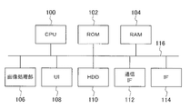
本実施の形態のプリントサーバ4は、CPU(Central Processing Unit)100、ROM(Read Only Memory)102、RAM(Random Access Memory)104、画像処理部106、UI(User Interface)108、HDD(Hard Disk Drive)110、通信IF(Interface)112、及びIF(Interface)114がバス116を介して接続されて構成されている。
The
CPU100は、ROM102やHDD110に記憶されているプログラムを実行し、プリントサーバ4全体の動作を制御する。ROM102には、CPU100が実行するプログラムやCPU100の処理に必要なデータ等が記憶されている。RAM104は、ワークメモリとして使用される。また、RAM104にはラスタライズ(画像形成情報からビットマップの多値画像データ(ラスターデータ)を生成する処理)や色変換処理等の画像処理により生成された各トナー毎の画像データ等を記憶するイメージメモリとしての領域も設けられている。
The
HDD110には、CPU100が実行するプログラムや各種データが記憶されている。
The
なお、CPU100が実行するプログラムを記憶するための記憶媒体は、HDD110やROM102に限定されない。例えば、フレキシブルディスクやDVDディスク、光磁気ディスクやUSBメモリ(ユニバーサルシリアルバスメモリ)等(不図示)であってもよいし、通信手段8に接続された他の装置の記憶装置であってもよい。
Note that the storage medium for storing the program executed by the
画像処理部106は、クライアント装置2から受信した画像形成情報に基づいて、ラスタライズや色変換処理等の各種画像処理を実行し、各トナーに対応する画像データを生成する。画像処理部106は、例えば、ASIC(Application Specific Integrated Circuit)やFPGA(Field-Programmable Gate Array)等により構成してもよい。画像処理部106の詳細な構成は後述する。
The
UI108は、例えば、液晶ディスプレイ等により構成され、CPU100の制御により各種画像やメッセージ等を表示する表示部と、例えば、キーボードやマウス等により構成され、利用者が操作することより各種情報が指定される操作部とにより構成される。
The
通信IF112は、通信手段8を介して他の装置とデータの送受信を行うためのインタフェースである。 The communication IF 112 is an interface for transmitting / receiving data to / from other devices via the communication unit 8.
IF114は、通信手段8を介さずにプリンタ6に接続するためのインタフェースである。
The
なお、前述したクライアント装置2も、プリントサーバ4と同様の構成である。ただし、クライアント装置2でCPUが実行するプログラムには、各種アプリケーションソフトや、前述の画像形成情報を生成して送信するためのプログラムなどが含まれる。
The
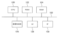
図3は、プリンタ6の構成の一例を示す図である。ここでは、通信手段8を介さずにプリントサーバ4に接続されたプリンタ6の構成の一例について説明する。
FIG. 3 is a diagram illustrating an example of the configuration of the
プリンタ6は、CPU(Central Processing Unit)120、ROM(Read Only Memory)122、RAM(Random Access Memory)124、画像形成部126、UI(User Interface)128、及びIF(Interface)130がバス132を介して接続されて構成されている。
In the
CPU120は、ROM122に記憶されているプログラム(例えば、プリントサーバ4から各トナー毎の二値画像データを受信し、該受信した二値画像データに基づいて画像が形成されるよう画像形成部126を制御するプログラムなどを含む)実行し、プリンタ6全体の動作を制御する。ROM122には、CPU120が実行するプログラムやCPU120の処理に必要なデータ等が記憶されている。RAM124は、ワークメモリとして使用される。
The
なお、CPU120が実行するプログラムを記憶するための記憶媒体は、ROM122に限定されない。例えば、フレキシブルディスクやDVDディスク、光磁気ディスクやUSBメモリ等(不図示)であってもよい。
Note that the storage medium for storing the program executed by the
画像形成部126は、プリントサーバ4から受信した二値画像データに基づいて画像を形成する。画像形成部126の構成は後述する。
The
IF130は、プリントサーバ4に接続するためのインタフェースである。
The
UI128は、例えばディスプレイ上にタッチパネルが重ねられたタッチパネルディスプレイ、及び操作ボタン等から構成される。UI128には、各種情報が表示され、また利用者が操作することにより様々な情報や設定が入力される。
The
なお、ここでは図示を省略するが通信手段8に直接接続されたプリンタ6の場合には、上記構成の他、通信手段8に接続するための通信IFが備えられている。
Although not shown here, the
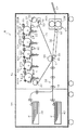
図4は、画像形成部126の概略構成を示した図である。
FIG. 4 is a diagram illustrating a schematic configuration of the
画像形成部126は、図4に示すように、記録媒体(本実施の形態では記録用紙P)に画像を形成する画像形成機構部12と、この画像形成機構部12へ記録用紙Pを給紙する給紙機構部14で構成されている。
As shown in FIG. 4, the
画像形成機構部12には、感光体20の回転方向(矢印A方向、以下プロセス方向という)の上流側から順に、低光沢のブラック(LK)、高光沢のイエロー(Y)、高光沢のマゼンタ(M)、高光沢のシアン(C)、高光沢のブラック(HK)の各色のトナーにより感光体20に形成された静電潜像を現像して、各色のトナー像を形成する画像形成ユニット18LK、18Y、18M、18C、18HKが配置されている。
The
すなわち、本実施の形態では、シアン、マゼンタ、イエローの各色のトナー像については、各々高光沢のトナー像が形成され、ブラックのトナー像については、光沢度が異なる2種類のトナー像を形成することが可能に構成されている。 That is, in the present embodiment, a high-gloss toner image is formed for each of the cyan, magenta, and yellow toner images, and two types of toner images having different gloss levels are formed for the black toner image. It is configured to be possible.
ここで、高光沢のトナーとは、定着後の画像の光沢度が予め定められた第1の範囲内となるトナーであり、低光沢のトナーは、定着後の画像の光沢度が第1の範囲より低い第2の範囲内となるトナーをいうものとする。すなわち、ここでいう「高光沢」或いは「低光沢」の文言は、いずれか一方に対する相対的な表現として用いており、互いを区別するために使用している。 Here, the high gloss toner is a toner in which the glossiness of the image after fixing falls within a predetermined first range, and the low gloss toner has a glossiness of the image after fixing of the first. The toner is in the second range lower than the range. That is, the term “high gloss” or “low gloss” is used as a relative expression for either one, and is used to distinguish each other.
本実施の形態では、画像形成ユニット18LKをプロセス方向の最上流側に配置し、低光沢のブラックのトナー像を形成する場合には、低光沢のブラックのトナー像が記録用紙Pの記録面に対して最上層に重ねられる(転写される)ように構成した。低光沢のトナー像が、記録用紙Pの記録面に対して2層目以下の層に形成されると、低光沢の効果が出にくいためである。 In the present embodiment, when the image forming unit 18LK is arranged on the most upstream side in the process direction to form a low gloss black toner image, the low gloss black toner image is formed on the recording surface of the recording paper P. On the other hand, it was configured to be overlaid (transferred) on the uppermost layer. This is because when the low-gloss toner image is formed on the second or lower layer with respect to the recording surface of the recording paper P, the low-gloss effect is difficult to obtain.
なお、以降、Y、M、C、HK、LKを区別する必要がある場合は、符号の末尾にY、M、C、HK、LKのいずれかを付し、Y、M、C、HK、LKを区別する必要がない場合は、これら末尾の符号を省略する。また、高光沢のブラック(HK)と低光沢のブラック(LK)とを区別しない場合には、HやLの記号を省略して単にブラック(K)と表現する。更にまた、単に「搬送方向」というときは、記録用紙Pの搬送方向をいう。 Hereinafter, when it is necessary to distinguish between Y, M, C, HK, and LK, Y, M, C, HK, and LK are added to the end of the code, and Y, M, C, HK, When it is not necessary to distinguish LK, these trailing signs are omitted. In addition, when the high gloss black (HK) and the low gloss black (LK) are not distinguished, the symbols H and L are omitted and simply represented as black (K). Furthermore, the “conveying direction” simply refers to the conveying direction of the recording paper P.
画像形成ユニット18は感光体20を備え、この感光体20の回りにはそれぞれ、感光体20の回転方向に順に、一次転写ロール22、クリーニング装置24、除電装置25、帯電器26、露光装置28、現像装置30が配設されている。
The
上記構成の画像形成ユニット18LK、18Y、18M、18C、18HKの下方には、支持ロール34と、プロセス方向に沿って配置された支持ロール32、33と、これら支持ロール34と支持ロール32、33に張架された無端状の中間転写ベルト36で構成された中間転写部材31が配設されている。
Below the image forming units 18LK, 18Y, 18M, 18C, and 18HK configured as described above, a
そして、画像形成ユニット18LK、18Y、18M、18C、18HKは、中間転写ベルト36の進行方向(矢印B方向)に、この順で一列に並んだ状態で配列されている。このとき、一次転写ロール22LK、22Y、22M、22C、22HKは、中間転写ベルト36を挟んで、各画像形成ユニット18LK、18Y、18M、18C、18HKの感光体20LK、20Y、20M、20C、20HKと対向する位置にある。
The image forming units 18LK, 18Y, 18M, 18C, and 18HK are arranged in a line in this order in the advancing direction (arrow B direction) of the
上記構成により、まず、感光体20が、帯電器26により表面が帯電され、露光装置28で露光されると、感光体20の表面に静電潜像が形成される。この静電潜像は、現像装置30によって現像されてトナー像となる。そして、感光体20上のトナー像は、一次転写ロール22に印加された転写バイアスによる静電吸引によって、中間転写ベルト36上に一次転写される。
With the above configuration, first, when the surface of the photoconductor 20 is charged by the
中間転写ベルト36にトナー像を転写した後、感光体20に残留した未転写残留トナーは、クリーニング装置24で除去される。そして、感光体20の表面は、除電装置25によって除電された後、次の画像形成サイクルのため、帯電器26で再び帯電される。
After the toner image is transferred to the
本実施の形態のプリンタ6では、カラー画像を形成する場合、各画像形成ユニット18LK、18Y、18M、18C、18HKの相対的な位置の違いを考慮したタイミングで、上記と同様の画像形成工程が各画像形成ユニット18LK、18Y、18M、18C、18HKにおいて行われ、中間転写ベルト36上に、ベルト面に対して下から低光沢のブラックのトナー像、イエローのトナー像、マゼンタのトナー像、シアンのトナー像(或いは、イエローのトナー像、マゼンタのトナー像、シアンのトナー像、高光沢のブラックのトナー像)の順に重ね合わせて転写して、カラー画像を形成する。なお、本実施の形態では、低光沢のブラックのトナー像と高光沢のブラックのトナー像とが同一の領域に重ね合わされて転写されることがないように制御される。
In the
また、例えば、ブラック単色で画像を形成する場合には、画像形成ユニット18LK、又は画像形成ユニット18HKで形成したトナー像が中間転写ベルト36上に転写され、白黒の画像が形成される。
Further, for example, when an image is formed in black only, the toner image formed by the image forming unit 18LK or the image forming unit 18HK is transferred onto the
一方、画像形成機構部12の側方には、給紙機構部14が配設されている。給紙機構部14には、記録用紙Pが収容された給紙カセット38、40が設けられている。記録用紙Pは、給紙カセット38、40のいずれか一方から、画像形成機構部12に給紙され、搬送機構42の複数の搬送ロール44によって二次転写位置Cに送られる。
On the other hand, a paper
二次転写位置Cとは、中間転写ベルト36を支持する支持ロール34と、支持ロール34に圧接する二次転写ロール48とで挟まれた位置のことであり、二次転写ロール48に印加された転写バイアスによる静電吸引力によって、中間転写ベルト36に形成されたトナー像が二次転写位置Cへ搬送された記録用紙Pに転写される。
The secondary transfer position C is a position sandwiched between the
なお、中間転写ベルト36上に残留した残留トナーは、支持ロール32近傍に配設された中間転写ベルトクリーニング装置50のクリーニングブレード52で掻き取られ、中間転写ベルト36上から除去される。
The residual toner remaining on the
二次転写位置Cの下流側には、2つのロール54、56に巻き掛けられた搬送ベルト58が設けられており、中間転写ベルト36上のトナー像が転写された記録用紙Pは、この搬送ベルト58によって搬送されて、搬送ベルト58の下流側に配設された定着装置60へ搬送される。
On the downstream side of the secondary transfer position C, a
そして、定着装置60の加圧ローラ60Aと加熱ローラ60Bで定着処理が施され、トナー像が記録用紙Pに定着される。つまり、記録用紙Pに画像が形成される。そして、この画像が形成された記録用紙Pはプリンタ6の外部に設けられた排紙トレイ57へ排出される。
Then, a fixing process is performed by the
なお、図1に示すように、中間転写ベルト36の転写面の反対側で、且つ、中間転写ベルト36を張架するプロセス方向上流側の支持ロール32と、感光体20LK(一次転写ロール22LK)の間には、ベルトリトラクト部材78が設けられている。
As shown in FIG. 1, a
また、感光体20Y(一次転写ロール22Y)と感光体20M(一次転写ロール22M)との間には、固定の支持部材80が設けられている。
Further, a fixed support member 80 is provided between the
ベルトリトラクト部材78は中間転写ベルト36に接離する支持部材を備え、該支持部材が不図示のモータにより上下する。また、画像形成ユニット18LKも、中間転写ベルト36に対して接離可能とされている。一方、中間転写ベルト36を挟んで、画像形成ユニット18LKの感光体ドラム20LKに対向して設けられた一次転写ロール22LKも、ベルトリトラクト部材78と同様な構成で、上下方向に移動可能とされている。
The
このような構成により、ベルトリトラクト部材78の支持部材が上昇すると、支持部材が中間転写ベルト36の裏面に接触して、図5に示すように、中間転写ベルト36の転写面が、感光体20HK、20Y、20M、20C、20LKの各々に接触する。また、中間転写ベルト36の転写面と反対側の面が、一次転写ロール22HK、22Y、22M、22C、22LKの各々に接触する。
With such a configuration, when the support member of the
また、ベルトリトラクト部材78の支持部材が下降すると、中間転写ベルト36の転写面が感光体20LKから離れる。これにより、図6に示すように、中間転写ベルト36の転写面が、感光体20HK、20Y、20M、20Cの各々に接触し、感光体20LKからは離間した状態となる。また、中間転写ベルト36の転写面と反対側の面が、一次転写ロール22HK、22Y、22M、22Cの各々に接触し、一次転写ロール22LKからは離間した状態となる。
Further, when the support member of the
更に、感光体20LKが中間転写ベルト36に接触していないとき、感光体20LKの回転駆動が停止され、画像形成ユニット18LKの画像形成動作が行われないようになっている。
Further, when the photoconductor 20LK is not in contact with the
形成する画像の全領域を高光沢YMCKの4色モードで形成する場合には、図6に示す状態で画像を形成し、領域毎に光沢度を異ならせ、高光沢の4色のトナーと共に低光沢のブラックのトナーも用いて画像を形成する場合には、図5に示す状態で画像を形成する。以下では、図5の状態において、高光沢の4色のトナーと共に低光沢のブラックのトナーも用いて画像を形成する場合の作用について説明する。 When the entire area of the image to be formed is formed in the high-gloss YMCK four-color mode, the image is formed in the state shown in FIG. 6, and the glossiness is different for each area. When an image is formed using glossy black toner, the image is formed in the state shown in FIG. Hereinafter, in the state of FIG. 5, an operation in the case of forming an image using four glossy toners and low glossy black toner will be described.
プリントサーバ4は、クライアント装置2から画像形成情報を受信すると、図7に示す処理ルーチンを実行する。この処理ルーチンのプログラムは、ROM102かHDD110に記憶されており、CPU100により実行される。
When the
ステップ200では、受信した画像形成情報を解析し、画像形成情報により形成される画像のオブジェクトを抽出する。オブジェクトとは、予め定められた属性を有する小領域の画像をいう。例えば、文字(一文字一文字ではなく、文字ブロック)、写真、グラフ、罫線、表(罫線で囲まれた行列要素をもつ文字集合)、及び表の各セル(表を構成する各マス目)等が予め属性として設定されているものとし、これら予め設定されている属性毎に画像データを分割する。このようにオブジェクト毎に画像データを分割することを、オブジェクトを抽出するという。なお、同一の属性であっても、隣接せず距離をおいて配置されている画像については、異なるオブジェクトとして抽出するようにしてもよい。
In
ステップ202では、各オブジェクトの光沢度を指定するための光沢指定画面をUI108に表示する。ユーザは、該光沢指定画面に従って、各オブジェクトの光沢度を指定する。各オブジェクトの光沢度は、定量的に指定しなくてもよく、定性的に指定するようにしてもよい。本実施の形態では、オブジェクトの光沢度を、「低光沢のLKのトナーの定着後の光沢度よりも高光沢のC、M、Y、HKのトナーの定着後の光沢度に近い光沢度」にしたい場合には、「高光沢」に指定し、オブジェクトの光沢度を「高光沢のC、M、Y、HKのトナーの定着後の光沢度よりも低光沢のLKのトナーの定着後の光沢度に近い光沢度」にしたい場合には、「低光沢」に指定するものとする。
In
ステップ204では、ユーザにより光沢指定があったか否かを判定する。ステップ204で否定判定した場合には、待機状態を継続し、ステップ204で肯定判定した場合には、ステップ206で、ユーザにより指定された光沢度を示す情報(以下、光沢指定情報)をオブジェクト毎に記憶する。
In
ステップ208では、全オブジェクトについて光沢指定済みか否かを判定する。ステップ208で否定判定した場合には、ステップ204に戻り、ステップ208で肯定判定した場合には、ステップ210に進む。
In
ステップ210では、受信した画像形成情報と、上記光沢指定情報とを画像処理部106に出力し、画像処理部106に画像処理を実行させ、各トナーに対応する画像データを生成させる。
In
ステップ212では、画像処理部106で生成された各トナーに対応する画像データをプリンタ6に出力することにより、プリンタ6で画像データに基づいた画像形成が行われるように制御する。
In
ここで、画像処理部106の構成及び画像処理部106で行われる画像処理について、詳細に説明する。図8に示すように、画像処理部106は、オブジェクト判定部140、ラスタライザ142、色変換処理部144、総量規制部146、ディザ処理部148、及びパラメータ保持部150を備えている。
Here, the configuration of the
オブジェクト判定部140は、画像形成情報と光沢指定情報とが入力されると、該画像形成情報が示す画像に含まれる各オブジェクトに対して、光沢指定情報が示す光沢度(高光沢か低光沢か)を示すタグを設定して、画像形成情報と各オブジェクト毎のタグとをラスタライザ142に出力する。
When the image formation information and the gloss designation information are input, the
ラスタライザ142は、画像形成情報に基づいてラスター処理を行い、ビットマップの多値画像データ(ラスターデータ)を、シアン、マゼンタ、イエロー、ブラックの各色毎に生成する。ラスタライザ142のラスター処理により得られる各色の画像データは、各画素の濃度値を示す多値画像データ(以下、画素データ)により構成される。ラスタライザ142は、生成した画素データと該画素データに対して設定されているタグ(画素データにより構成されるオブジェクトに対して設定されているタグ)とを色変換処理部144に出力する。ラスタライザ142から出力されるシアン、マゼンタ、イエロー、ブラックの各色の画素データを、画素データC1、M1、Y1、K1と表現する。
The
色変換処理部144は、ラスタライザ142から入力された画素データC1、M1、Y1、K1を、該画素データに設定されているタグに応じたパラメータが設定された変換テーブル(4入力4出力の4次元ルックアップテーブル(DLUT))により、画素データC2、M2、Y2、HK1、又はC2、M2、Y2、LK1に変換して出力する。ここで、HK1は、高光沢K色トナーに対応する画素データであり、LK1は低光沢K色トナーに対応する画素データである。
The color
本実施の形態では、ブラックのトナーについては、タグに応じて光沢度が異なる2種類のトナーから1つを選択して使用するようにしており、同一の領域に2種類のK色トナーの各々を用いることはない。従って、ここでは、入力がC1、M1、Y1、K1で、出力がC2、M2、Y2、HK1、のDLUTと、入力がC1、M1、Y1、K1で、出力がC2、M2、Y2、LK1のDLUTとを切り替えて用いて、HK1及びLK1の一方にK1の値がそのままセットされるようにしている。これにより、ラスタライザ142から出力されたタグが、高光沢を示していた場合には、画素データC1、M1、Y1、K1が画素データC2、M2、Y2、HK1に変換されて出力され、LK1は出力されない。また、タグが低光沢を示していた場合には、画素データC1、M1、Y1、K1が画素データC2、M2、Y2、LK1に変換されて出力され、HK1は出力されない。以下、ここで画素データが出力されなかった方のブラックを非出力ブラックと呼称する。
In this embodiment, as the black toner, one of two types of toners having different glossiness depending on the tag is selected and used, and each of the two types of K color toners is used in the same region. Is not used. Therefore, here, the input is C 1 , M 1 , Y 1 , K 1 , the output is C 2 , M 2 , Y 2 , HK 1 , and the input is C 1 , M 1 , Y 1 , K 1 , the output of C 2 , M 2 , Y 2 , and LK 1 is switched and used so that the value of K 1 is set to one of HK 1 and LK 1 as it is. Thereby, when the tag output from the
なお、色変換処理部144で用いられる変換テーブル(DLUT)のパラメータは、タグ毎に、パラメータ保持部150のメモリに保持(記憶)されている。色変換処理部144は、まず、ラスタライザ142から入力されたタグをパラメータ保持部150に出力する。パラメータ保持部150は、色変換処理部144から入力されたタグに応じたパラメータが設定された変換テーブルを色変換処理部144に出力する。色変換処理部144は、パラメータ保持部150から入力された変換テーブルに従って、上記のように画素データC1、M1、Y1、K1を変換する。
Note that the parameters of the conversion table (DLUT) used in the color
なお、ここで挙げた例では、画素データK1を単純にHK1又はLK1に置き換えるだけであるため、各色の画素データは上記DLUTにより以下のように変換される。 In the example given here, since the pixel data K 1 is simply replaced with HK 1 or LK 1 , the pixel data of each color is converted by the DLUT as follows.
C2=C1
M2=M1
Y2=Y1
HK1=K1(タグが高光沢を示していた場合)
LK1=K1(タグが低光沢を示していた場合)
C 2 = C 1
M 2 = M 1
Y 2 = Y 1
HK 1 = K 1 (when the tag shows high gloss)
LK 1 = K 1 (when tag shows low gloss)
すなわち、シアン、マゼンタ、イエローの各色の画素データについては、色変換処理部144に入力された画素データがそのまま出力される。
That is, the pixel data input to the color
なお、変換方法は上記に限定されない。例えば、高光沢のブラックのトナー像と低光沢のブラックのトナー像とは、同じ量のトナーを用いても色味(色再現性)が異なってしまうことがある。これを考慮して、画素データK1を単純にHK1又はLK1に置き換えるだけの変換テーブルではなく、使用するブラックのトナーが高光沢のトナーか低光沢のトナーかに応じて色味が変動しないように(色再現の差が小さくなるように)、各色の濃度値を調整する変換テーブルを用いて、画素データC1、M1、Y1、K1を変換するようにしてもよい。 The conversion method is not limited to the above. For example, a high gloss black toner image and a low gloss black toner image may have different colors (color reproducibility) even when the same amount of toner is used. Considering this, the color changes depending on whether the black toner to be used is a high gloss toner or a low gloss toner, rather than simply converting the pixel data K 1 to HK 1 or LK 1 The pixel data C 1 , M 1 , Y 1 , and K 1 may be converted using a conversion table that adjusts the density value of each color so as not to reduce the difference in color reproduction.
例えば、中間転写ベルト36に一次転写された後のトナー像の一部が感光体20側に再び転写(逆転写)されてしまう、いわゆるリトランスファーが発生する場合がある。このリトランスファーは、1次転写位置で発生する放電により中間転写ベルト36に転写されたトナー像の表層部のトナーが逆極性化し、この逆極性化したトナーが感光体20側に静電的に引き寄せられること等により発生する。これにより、濃度低下が発生する。このリトランスファーは、プロセス方向上流側の画像形成ユニット18により形成され中間転写ベルト36に転写されたトナー像が、これより下流側の画像形成ユニット18の感光体に逆転写される現象であるため、画像形成ユニット18の位置に応じて、リトランスファーによる影響を受けるトナー像と受けないトナー像とがある。例えば、プロセス方向最下流側に位置する画像形成ユニット18HKの場合には、それより下流側に画像形成ユニットが存在しないため、画像形成ユニット18HKにより形成されるトナー像はリトランスファーの影響はないが、それより上流側の画像形成ユニット18により形成されるトナー像は、リトランスファーの影響を受けることとなる。また、リトランスファーだけでなく、刷り順(トナー像の重ね順序)によっても色味が変動することがある。また、光沢度によっては、発色性が異なるため、(光沢度が高いほど、トナー像の表面の平滑度が高く、発色性が高くなる)、高光沢のブラックのトナーを使用して画像を形成した場合と、低光沢のブラックのトナーを使用して画像を形成した場合とでは、同じトナー量でトナー像を形成したとしても、色味が異なる場合がある。
For example, there is a case where so-called retransfer occurs in which a part of the toner image after the primary transfer to the
そこで、パラメータ保持部150が、タグに応じてCMY色についても異なるパラメータを保持し、入力されたタグに応じたパラメータを設定した変換テーブルを色変換処理部144に出力するように構成してもよい。また、パラメータ保持部150が保持する変換テーブルのパラメータが、HK1及びLK1の値のみがタグに応じて異なるものであってもよいし、HK1やLK1だけでなくC2、M2、Y2の値も異なるものであってもよい。より具体的には、タグが高光沢を示していた場合には、低光沢の場合よりも、各画素データの濃度値が低めに変換されるようパラメータを設定する等である。これにより、色味(色再現性)のばらつきが小さくなる。
Accordingly, the
色変換処理部144の後段に位置する総量規制部146は、色変換処理部144から入力された画素データC2、M2、Y2、HK1を、総量規制処理された画素データC3、M3、Y3、HK2に変換して出力するか、又は総量規制部168から入力された画素データC2、M2、Y2、LK1を、総量規制処理された画素データC3、M3、Y3、LK2に変換して出力する。
The total
記録用紙Pに画像を形成する際にトナー量の合計がある閾値を超えると記録用紙Pへのトナーの定着が安定せず、この状態で排出された記録用紙に他の記録用紙Pが重なって排出されると、該他の記録用紙Pにトナーが付着して色写りしたり、記録用紙P同士がくっついてしまったりする等の問題が発生する場合がある。そこで、本実施の形態では、総量規制部146により、記録用紙Pに付着させるトナーの総量を制限するために多値画像データを補正する総量規制処理を行う。
When the total amount of toner exceeds a certain threshold when forming an image on the recording paper P, the fixing of the toner to the recording paper P is not stable, and another recording paper P overlaps with the recording paper discharged in this state. When the paper is discharged, there may be a problem in that the toner adheres to the other recording paper P and the color appears, or the recording papers P stick to each other. Therefore, in the present embodiment, the total
総量規制処理では、シアン、マゼンタ、イエロー、ブラックの各色の多値画像データの1画素あたりの濃度値の合計値(各画素データの合計値)が予め定められた上限値(以下、総量規制値TACという)を超えないように、シアン、マゼンタ、イエロー、ブラック各色の濃度値がそれぞれ同じ割合で減少するように補正する。 In the total amount restriction process, a total value of density values per pixel (total value of each pixel data) of multi-value image data of each color of cyan, magenta, yellow, and black is determined in advance (hereinafter referred to as a total amount restriction value). The density value of each color of cyan, magenta, yellow, and black is corrected so as to decrease at the same rate.
具体的には、色変換処理部144から入力された画素データC2、M2、Y2、HK1が入力された場合において、C2+M2+Y2+HK1≦TACであるときには、入力された画素データの各々をそのまま変換せずに出力する。また、C2+M2+Y2+HK1>TACであるときには、各色の濃度値(画素データ)がそれぞれ同じ割合で減少するように処理して出力する。なお、色変換処理部144から画素データC2、M2、Y2、LK1が入力された場合も上記と同様に総量規制処理して出力する。ここでは、シアン、マゼンタ、イエロー、ブラック各色の濃度値がそれぞれ同じ割合で減少するように補正する例について説明したが、例えば、YMCの各濃度値を一律に減らして、Kの濃度値はそのままとしたり、逆にYMCの濃度値はそのままで、Kの濃度値を減らしたりするようにしてもよい。
Specifically, when pixel data C 2 , M 2 , Y 2 , and HK 1 input from the color
なお、黒やグレイは、シアン、マゼンタ、イエロー、ブラックの4色のトナーを混ぜても表現できるが、ブラックだけで印刷することが可能であるため、総量規制処理において、シアン、マゼンタ、イエローの3色をブラックに置き換える(CMYを一律に減少させ、ブラックのトナー量を増やす)画像処理(この処理は、一般的に、UCR処理と呼ばれる)を施して、色味の変動を抑えて4色のトナー量の合計値が総量規制値以下となるように処理してもよい。また、総量規制処理を、ルックアップテーブルを用いて行ってもよいし、関数演算により行ってもよい。 Note that black and gray can be expressed by mixing toners of four colors, cyan, magenta, yellow, and black. However, since printing can be performed using only black, cyan, magenta, and yellow can be printed in the total amount restriction process. Three colors are replaced with black (CMY is uniformly reduced and the amount of black toner is increased). Image processing (this process is generally referred to as UCR processing) is performed to suppress variations in hues and reduce the four colors. The total toner amount may be processed so as to be equal to or less than the total amount regulation value. Further, the total amount regulation processing may be performed using a lookup table or may be performed by function calculation.
総量規制部146の後段に位置するディザ処理部148は、総量規制部146から出力された画素データC3、M3、Y3、HK2(又はLK2)に対して、ディザ閾値を配列した色毎の閾値パターン(以下、ディザマトリクス)を用いたディザ処理を施し、多値画像データを2値化した二値画像データを生成して出力する。なお、本実施の形態において、高光沢のブラックの画素データ(HK2)に対応するディザマトリクス、及び低光沢のブラックの画素データ(LK2)に対応するディザマトリクスのスクリーン線数は同一か或いは略同一(例えば、その差が予め定められた線数S1未満)とし、また、そのスクリーン角度も同一か略同一(例えば、その差が予め定められた角度S2未満)とする。なお、シアン、マゼンタ、イエロー、ブラックの各々のディザマトリクスのスクリーン線数は同一か或いは略同一(例えば、その差が予め定められた線数S1未満)とし、また、そのスクリーン角度については、(ブラックがHKであってもLKであっても)、色間で干渉が生じないように、各色間のスクリーン角度差が予め定められた角度S3(ここでS2<S3)以上異なるように設定する。
The
すなわち、本実施の形態では、C、M、Y、HK、LKのいずれについても、互いにスクリーン線数が同一又は略同一のディザマトリクスを用いてディザ処理を施している。スクリーン線数が大きく異なると、スクリーン線数の高い方の色に比べてスクリーン線数が低い色のドットの荒さが目立ち、画質が低下することによる。一方、スクリーン角度は色毎にある程度異ならせるようにして、色間で干渉が生じないようにしている。 In other words, in the present embodiment, dither processing is performed for all of C, M, Y, HK, and LK using dither matrices having the same or substantially the same screen line number. If the number of screen lines differs greatly, the roughness of dots having a lower number of screen lines is more conspicuous than the color having the higher number of screen lines, resulting in a decrease in image quality. On the other hand, the screen angle is varied to some extent for each color so that no interference occurs between colors.
なお、S3の値は、その値以上のスクリーン角度差を設けることにより、色間で干渉が生じない大きさとする。例えば、予め実験等により干渉が発生しないS2、S3を求めておき、これを満たすようにディザマトリクスを設定しておく。なお、スクリーン角度は、例えば、水平軸に対してシアン15度、ブラック45度、マゼンタ75度、イエロー30度、というように設定してもよく、複数の色間で等間隔に異ならせる必要はない。 Note that the value of S3 is set such that interference does not occur between colors by providing a screen angle difference equal to or greater than that value. For example, S2 and S3 at which interference does not occur are obtained in advance by experiments or the like, and a dither matrix is set so as to satisfy this. For example, the screen angle may be set to 15 degrees cyan, 45 degrees black, 75 degrees magenta, and 30 degrees yellow with respect to the horizontal axis. Absent.
ディザ処理により生成され出力された二値画像データは、プリンタ6に出力される。なお、また、前述の非出力ブラックについては、ディザ処理部148で、濃度値0%の二値画像データを生成して出力してもよいし、二値化画像データを出力しないままとしてもよい。
The binary image data generated and output by the dither processing is output to the
プリンタ6は、入力された二値画像データに基づいて、画像を形成する。なお、非出力ブラックについては、濃度値0%の二値画像データがプリンタ6に入力されるか、或いは二値画像データ自体がプリンタ6に入力されないため、該非出力ブラックのトナー像は形成されない。
The
なお、仮に、HKとLKのディザマトリクスのスクリーン線数及びスクリーン角度を同一として、高光沢のブラックトナーと低光沢のブラックのトナーとを、同一領域に使用する(すなわち、高光沢のブラックのトナー像と低光沢のブラックのトナー像とを重ねて転写して画像を形成する場合)には、スキューや区間倍率変動など、露光系の変形による画像の変形により、大きなスクリーン周期の干渉が発生し、モアレ、濃度ムラや光沢ムラが生じる場合がある。また、画像の変形を改善するために、画素単位でドットの位置を動かすことで補正しようとすると、デジタル的な画素位置変動処理により、補正点では補正方向にドットが重なるが、それ以外の点では、ずれていることを許容するため、短周期の干渉縞が発生することがある。一方、HKとLKを異なる角度のディザにすると、各色毎のベクトルの角度を充分にとることができず、他の色のディザとの干渉を回避できなくなる。なお、干渉を回避するためにディザ処理ではなく、固定周波数成分のないFMスクリーンを用いて(誤差拡散処理を行って)二値化処理したり、充分に周波数の高いスクリーンを用いて二値化処理したりすると、粒状性が悪化して見えることがある。特に、ブラックは粒状性の目視感度が高いため、粒状性の悪化が認識されやすい。 It is assumed that the screen line number and screen angle of the HK and LK dither matrices are the same, and the high gloss black toner and the low gloss black toner are used in the same region (that is, the high gloss black toner). Image and low-gloss black toner image transferred to form an image), a large screen cycle interference occurs due to the deformation of the image due to deformation of the exposure system, such as skew and interval magnification fluctuations. , Moire, density unevenness and gloss unevenness may occur. In order to improve the deformation of the image, if correction is attempted by moving the dot position in units of pixels, the dot overlaps in the correction direction at the correction point due to digital pixel position variation processing. Then, in order to allow deviation, short-period interference fringes may occur. On the other hand, if HK and LK are dithered at different angles, the vector angle for each color cannot be taken sufficiently, and interference with other color dithers cannot be avoided. Instead of dithering to avoid interference, binarization is performed using an FM screen without a fixed frequency component (by performing error diffusion processing), or binarization is performed using a screen having a sufficiently high frequency. When processed, the graininess may appear to deteriorate. In particular, since black has high visual sensitivity of graininess, it is easy to recognize deterioration of graininess.
しかしながら、本実施の形態では、高光沢のブラックトナー像と低光沢のブラックのトナー像とが、同一領域に重ねて転写されることがなく、高光沢のブラックに対応するディザマトリクス、及び低光沢のブラックに対応するディザマトリクスのスクリーン角度及びスクリーン線数を同一か或いは略同一としても、干渉が抑制される。また、粒状性も悪化しない。 However, in this embodiment, the high-gloss black toner image and the low-gloss black toner image are not transferred over the same region, and the dither matrix corresponding to the high-gloss black and the low-gloss Even if the screen angle and the number of screen lines of the dither matrix corresponding to black are the same or substantially the same, interference is suppressed. Further, the graininess does not deteriorate.
なお、本実施の形態では、形成する画像を複数の領域に分割したときの各領域に対して光沢度を指定する一例として、オブジェクト毎に高光沢か低光沢かを指定する例について説明したが、光沢度の指定がオブジェクト単位の指定に限定されるものではなく、画像の位置に応じて光沢度を指定するようにしてもよいし(例えば、画像の上半分は高光沢、下半分は低光沢等)、特に限定されない。 In this embodiment, an example in which high gloss or low gloss is specified for each object has been described as an example of specifying glossiness for each area when an image to be formed is divided into a plurality of areas. However, the specification of the glossiness is not limited to the specification of the object unit, but the glossiness may be specified according to the position of the image (for example, the upper half of the image is high gloss and the lower half is low). Gloss, etc.), not particularly limited.
また、ユーザが画像形成の都度光沢度を指定するのではなく、予めオブジェクトの種類と画像形成する際の光沢度とを対応付けてプリントサーバ4のHDD110等に記憶して設定おき(例えば、文字オブジェクトに対しては低光沢、写真オブジェクトに対しては高光沢等)、プリントサーバ4で画像形成情報より抽出したオブジェクトに対して、該オブジェクトの種類に対応して記憶されている光沢を示す光沢指定情報を設定してもよい。
In addition, the user does not specify the glossiness every time the image is formed, but the object type and the glossiness when the image is formed are associated with each other and stored in the
なお、本実施の形態では、色変換処理部144において、タグに基づき、C/M/Y/K→C/M/Y/HKの4入力4出力のルックアップテーブル(DLUT)もしくは、C/M/Y/K→C/M/Y/LKの4入力4出力のDLUTを切り替えて、色変換処理をする例について説明したが、これに限定されるものではない。例えば、C/M/Y/K/タグ→C/M/Y/HK/LKの5入力5出力のDLUTを用いて色変換処理するようにしてもよい。なお、HK及びLKについては、その一方がタグに応じてNULL(非出力)或いは濃度値0%となるようにDLUTのパラメータが設定されているものとする。このDLUTを用いる場合には、変換テーブルの切り替えは不要となる。
In this embodiment, the color
また、本実施の形態では、色変換処理部144から、高光沢のブラックの画素データと低光沢のブラックの画素データが排他的に出力される例について説明したが、これに限定されず、例えば、トナー像を形成しない方のブラックについては、濃度値0%の画素データを出力するようにしてもよい。より具体的には、色変換処理部144でC/M/Y/K4入力でC/M/Y/HK/LK5出力のDLUTを用いて変換する。そして、後段の総量規制部146を、濃度値0%のブラックの画素データについては、濃度値0%を維持した状態で後段のディザ処理部148に出力されるように構成する。
In the present embodiment, an example in which high-gloss black pixel data and low-gloss black pixel data are exclusively output from the color
また、画像処理部106を、図9に示すように構成してもよい。この例では、画像処理部106は、オブジェクト判定部160、ラスタライザ162、色変換処理部164、黒置換部166、総量規制部168、ディザ処理部170、及びパラメータ保持部172を備えている。
Further, the
ここで、オブジェクト判定部160は、上記図8を用いて説明したオブジェクト判定部140と同様に動作するため、説明を省略する。
Here, the
ラスタライザ162は、画像形成情報に基づいてラスター処理を行い、ビットマップの多値画像データを、R(Red)、G(Green),B(Blue)の各色毎に生成してタグと共に出力する。ラスタライザ182のラスター処理により得られる各色の多値画像データは、画素毎の濃度値(画素データ)により構成される。ラスタライザ182は、生成した画素データと該画素データに対して設定されているタグ(該画素データが構成するオブジェクトに対して設定されているタグ)とを色変換処理部164に出力する。ラスタライザ142から出力されるRGB各色の画素データを、画素データR、G、Bと表現する。
The
色変換処理部164は、ラスタライザ162から入力された画素データR、G、Bを、該画素データと共に入力されたタグに応じたパラメータが設定された変換テーブル(3入力3出力の3次元ルックアップテーブル)により、画素データC1、M1、Y1に変換して、色変換前の画素データR、G、Bと共に入力されたタグと共に出力する。なお、色変換処理部164で用いられる変換テーブルのパラメータは、タグ毎に、パラメータ保持部172のメモリに保持(記憶)されている。色変換処理部144は、まず、ラスタライザ142から入力されたタグをパラメータ保持部172に出力する。パラメータ保持部172は、色変換処理部164から入力されたタグに応じたパラメータが設定された変換テーブルを色変換処理部164に出力する。色変換処理部164は、パラメータ保持部172から入力された変換テーブルに従って、上記のように画素データR、G、Bを画素データC1、M1、Y1に変換する。ここで、タグに応じて変換テーブルのパラメータを異ならせるのは、前述したように、リトランスファーや刷り順、或いは光沢度等の影響により、画像の形成に、高光沢のブラックのトナーを用いる場合と、低光沢のブラックのトナーを用いる場合とでは、色再現性が異なることがあるためである。そこで、色再現性がばらつかないように、タグ(高光沢か低光沢かを示す情報)に基づいて、変換テーブルのパラメータを異ならせ、各色の各画素データ(濃度値)を調整するようにしている。
The color
色変換処理部164の後段に位置する黒置換部166は、色変換処理部164から入力された画素データC1、M1、Y1を、該画素データと共に入力されたタグに応じて、画素データC2、M2、Y2、HK1に変換して出力するか、画素データC2、M2、Y2、LK1に変換して出力する。ここでは、前述したUCR処理を行って、画素データC2、M2、Y2、及びブラックの画素データHK1、LK1を生成するようにしている。ここで、ブラックの画素データについては、タグが高光沢を示している場合には、画素データC2、M2、Y2の濃度値を減らして高光沢のブラックの画素データHK1の濃度値を増やし、タグが低光沢を示している場合には、画素データC2、M2、Y2の濃度値を減らして低光沢のブラックの画素データLK1の濃度値を増やすように処理する。
The
黒置換部166の後段に位置する総量規制部168は、黒置換部166から入力された画素データC2、M2、Y2、HK1を、総量規制処理された画素データC3、M3、Y3、HK2に変換して出力するか、又は総量規制部168から入力された画素データC2、M2、Y2、LK1を、総量規制処理された画素データC3、M3、Y3、LK2に変換して出力する。総量規制部168の総量規制処理は、図8を用いて説明した総量規制部146での総量規制処理と同様に行えばよいため、ここでは説明を省略する。
The total
総量規制部168の後段に位置するディザ処理部170は、総量規制部168から出力された各画素データに対して、各色毎の閾値マトリクス(ディザマトリクス)を用いたディザ処理を施して、多値画像データを2値化した二値画像データを生成して出力する。ここで行われるディザ処理、及びディザ処理に用いられるディザマトリクスは、図8を用いて説明したディザ処理部148での処理及びディザマトリクスと同様であるため、説明を省略する。
The
なお、図9では、色変換処理部164において、R/G/B→C/M/Yの3入力3出力のLUTのパラメータをタグに応じて切り替えて用いて、色変換処理する例について説明したが、例えば、R/G/B→C/M/Y/HKの3入力4出力のDLUT及びR/G/B→C/M/Y/LKの3入力4出力のDLUTをタグに応じて切り替えて用いて色変換処理するようにしてもよい。この構成の場合には、黒置換部166は設けなくてもよい。
FIG. 9 illustrates an example in which the color
また、R/G/B/タグ→C/M/Y/HK/LKの4入力5出力のDLUTを用いて色変換処理するようにしてもよい。このとき、HK及びLKについては、その一方がタグに応じてNULL(非出力)或いは濃度値0%となるようにDLUTのパラメータが設定されているものとする。このDLUTを用いる場合には、変換テーブルの切り替えが不要となる。 Further, color conversion processing may be performed using a 4-input 5-output DLUT of R / G / B / tag → C / M / Y / HK / LK. At this time, it is assumed that the parameters of DLUT are set so that one of HK and LK has NULL (non-output) or a density value of 0% according to the tag. When this DLUT is used, it is not necessary to switch the conversion table.
また、画像処理部106を、図10に示すように構成してもよい。この例では、画像処理部106は、オブジェクト判定部180、ラスタライザ182、色変換処理部184、黒置換部186、ディザ処理部188、及びパラメータ保持部190を備えている。
Further, the
ここで、オブジェクト判定部180、及びラスタライザ182は、上記図8を用いて説明したオブジェクト判定部140、及びラスタライザ142と同様に動作するため、説明を省略する。
Here, the
色変換処理部184は、ラスタライザ182から入力された画素データC1、M1、Y1、K1を、該画素データと共に色変換処理部184から入力されたタグに応じたパラメータが設定された変換テーブル(4入力4出力の4次元ルックアップテーブル)により、画素データC2、M2、Y2、K2に変換して出力する。色変換処理部184で用いられる変換テーブルのパラメータは、タグ毎に、パラメータ保持部190のメモリに保持(記憶)されている。色変換処理部184は、変換テーブルによる変換前に、ラスタライザ182から出力されたタグをパラメータ保持部190に出力する。パラメータ保持部190は、色変換処理部184から入力されたタグに応じたパラメータが設定された変換テーブルを色変換処理部184に出力する。色変換処理部184は、パラメータ保持部190から入力された変換テーブルに従って画素データC1、M1、Y1、K1を変換する。
The color
なお、この色変換では、前述したように、リトランスファーの有無や刷り順、或いは光沢度の違い等により、高光沢のブラックのトナー像と低光沢のブラックのトナー像とで色再現性が異なってしまうことがあることを考慮して、使用するブラックのトナーが高光沢のトナーか低光沢のトナーかに応じて色再現性が変動しないように、タグに応じて、各色の濃度値を調整する変換テーブルを用いて、画素データC1、M1、Y1、K1を変換するようにしている。 In this color conversion, as described above, the color reproducibility differs between the high gloss black toner image and the low gloss black toner image due to the presence or absence of retransfer, the printing order, or the difference in glossiness. Depending on the tag, adjust the density value of each color so that the color reproducibility does not vary depending on whether the black toner used is a high gloss toner or a low gloss toner. The pixel data C 1 , M 1 , Y 1 , and K 1 are converted using the conversion table.
色変換処理部184の後段に位置する黒置換部186は、色変換処理部184から入力された画素データC2、M2、Y2、K2を、該画素データと共に入力されたタグに応じて、画素データC3、M3、Y3、HKに変換して出力するか、画素データC3、M3、Y3、LKに変換して出力する。ここでは、タグに応じてK2をHKか又はLKに置き換え、CMY各色の画素データについてはそのまま出力するようにしてもよいし、前述したUCR処理を行って、タグに応じて画素データC3、M3、Y3、及びブラックの画素データ(HK又はLK)を生成するようにしてもよい。なお、この黒置換部186は総量規制の機能も兼ね備えており、各色の画素データの合計値が総量規制値TACを超えないように変換される。
The
黒置換部186の後段に位置するディザ処理部188は、黒置換部186から出力された各画素データに対して、各色毎の閾値マトリクス(ディザマトリクス)を用いたディザ処理を施して、多値画像データを2値化した二値画像データを生成して出力する。ここで行われるディザ処理、及びディザ処理に用いられるディザマトリクスは、図8を用いて説明したディザ処理部148での処理及びディザマトリクスと同様であるため、説明を省略する。
The
なお、上記実施の形態及び図9,図10を用いて説明した変形例では、画像処理部106をハードウェアにより構築して画像処理を実行する場合を例に挙げて説明したが、画像処理部106の機能を実行するソフトウェアにより上記画像処理を行うようにしてもよい。
In the modification described with reference to the above embodiment and FIG. 9 and FIG. 10, the case where the
図11は、図8に示す画像処理部106と同様の画像処理を実行する処理ルーチンの流れを示すフローチャートである。この処理ルーチンのプログラムは、HDD110或いはROM102等の記憶手段に記憶され、CPU100により実行される。なお、ここでは、図8に示す画像処理部106の機能をソフトウェアにより実行する場合を例に挙げるが、図9,図10においても同様にソフトウェアにより実行する場合には、上記で説明した各構成要素の処理を順に実行する流れとなる(図示省略)。
FIG. 11 is a flowchart showing the flow of a processing routine for executing image processing similar to that of the
ステップ240では、オブジェクト判定(タグの設定)を行う。この処理は、図8のオブジェクト判定部140により行われる機能に相当する。ステップ242では、画像形成情報に基づいて、ラスタライズを行う。この処理は、図8のラスタライザ142により行われる機能に相当する。
In
ステップ244では、着目画素の画素データを抽出し、ステップ246では、該画素データに設定されているタグが高光沢を示しているか否かを判定する。ステップ246で肯定判定した場合には、ステップ248で、高光沢用のパラメータが設定された変換テーブルによる色変換処理を行う。また、ステップ246で否定判定した場合には、タグが低光沢を示しているため、ステップ250で、低光沢用のパラメータが設定された変換テーブルによる色変換処理を行う。
In
ステップ252では、全画素データについて変換テーブルを用いた変換処理が終了したか否かを判定し、否定判定した場合には、ステップ244に戻り、次の画素データを着目画素の画素データとして抽出して、上記と同様の処理を繰り返す。また、ステップ252で肯定判定した場合には、ステップ254に進む。
In
なお、ステップ244からステップ252までの処理が、図8の色変換処理部144及びパラメータ保持部150により行われる機能に相当する。
Note that the processing from
ステップ254では、総量規制処理を行う。この処理は、図8の総量規制部146により行われる機能に相当する。ステップ156では、ディザ処理を行う。この処理は、図8のディザ処理部148により行われる機能に相当する。
In
また、上記実施の形態では、複数の画像形成ユニット18をプロセス方向に配置したタンデム型の画像形成部126を例に挙げて説明したが、これに限定されるものではなく、例えば、図12に示すように、回転式の現像装置410が設けられた画像形成部400であってもよい。
In the above embodiment, the tandem type
感光体401は図示しないモータで矢印Aの方向に回転されるように設けられている。感光体401の周囲には、帯電ロール408、露光装置409、現像装置410、一次転写器402、及びクリーニング装置411が配置されている。
The
帯電ロール408は、感光体401の表面を帯電し、露光装置409は、画像データに応じて、帯電した感光体401の表面をレーザビームによって露光して静電潜像を形成する。
The charging
現像装置410には、高光沢のY、M、C、K色のトナーを用いる現像器410Y、410M、410C、410HKと、低光沢のK色のトナーを用いる現像器410LKが周方向に沿って配置されており、各現像器410Y,410M,410C,410HK、410LKは、感光体401上の静電潜像をそれぞれ高光沢のC,M、Y、K色のトナー、或いは低光沢のK色トナーで現像する。現像する際には、図示しないモータによって現像装置410を矢印R方向に回転させ、当該現像器が感光体401の潜像画像に対向するように位置合わせされる。
The developing
感光体401上に現像された各トナー画像は、一次転写器402によって中間転写ベルト403に順次転写されて、各トナー画像が重ね合わされる。中間転写ベルト403にはベルトクリーニング416が設けられ、中間転写ベルト403上の残留トナーがクリーニングブレードで掻き落とされる。
The toner images developed on the
記録用紙カセット417,418から引き出しロール419,420で搬送路に引き出された記録用紙はロール対421,422,423によって2次転写器404の転写位置に搬送される。中間転写ベルト403上に形成されたトナー像はこの転写位置で記録用紙上に転写され、定着装置424で熱定着されて排出部425又は本体上面に排出される。
The recording paper drawn from the
上記画像形成部400も、上記実施の形態で説明したように画像を形成する画像形成部として適用される。
The
なお、上記画像形成部400を用いて、低光沢のK色トナーを用いて画像を形成するときは、低光沢のK色トナー像が記録用紙の記録面に対して最上層に転写される刷り順で画像を形成するようプリントサーバ4からプリンタ6に対して制御命令を送信して画像形成部400を制御する。
When an image is formed by using the low-gloss K color toner using the
また、ここでは、上記実施の形態では、中間転写ベルトを介して記録媒体に画像を形成するプリンタを例に挙げて説明したが、感光体から直接記録媒体にトナー像を転写して定着させるプリンタであってもよい。 Here, in the above-described embodiment, a printer that forms an image on a recording medium via an intermediate transfer belt has been described as an example. However, a printer that transfers and fixes a toner image directly from a photoreceptor to a recording medium. It may be.
また、上記実施の形態では、高光沢のCMYKトナーと低光沢のKトナーを用いて画像を形成するプリンタ6を例に挙げて説明したが、これに限定されず、低光沢のCMYKトナーと高光沢のKトナーを用いて画像を形成するプリンタであってもよい。また、高光沢のCMYKトナーと低光沢のCトナーとを用いて画像を形成するプリンタであってもよいし、高光沢のCMYKトナーと低光沢のMトナーを用いて画像を形成するプリンタであってもよいし、高光沢のCMYKトナーと低光沢のYトナーを用いて画像を形成するプリンタであってもよい。こうした構成の場合も、上記実施の形態と同様に、高光沢が指定されている領域(画像)については、高光沢のトナー像が記録用紙の記録面に対して最上層に形成され、低光沢が指定されている領域(画像)については、低光沢のトナー像が記録用紙の記録面に対して最上層に形成されるように構成する。また、同じ色で定着後の光沢度が異なるトナーにより形成されたトナー像の各々が同じ領域に重ねて形成されないようにする。更にまた、ディザ処理においては、定着後の光沢度が異なり同じ色のトナーの多値画像データの各々を、スクリーン角度が同じ又はその差が予め定められた角度S2未満で、スクリーン線数が同じ又はその差が予め定められた線数S1未満の閾値パターンを用いて、二値画像データに変換し、異なる色のトナーの多値画像データの各々を、スクリーン角度の差が予め定められた角度S3以上異なるスクリーン角度で、且つスクリーン線数が同じ又はその差が予め定められた線数S1未満の閾値パターンを用いて、二値画像データに変換する。
In the above embodiment, the
また、高光沢のCMYKトナーと低光沢のCKトナーを用いて画像を形成するプリンタとしてもよい。タンデム型の場合には、低光沢のCKの画像形成ユニットが、高光沢のCMYKの画像形成ユニットよりプロセス方向上流側に位置するように構成する。なお、このプリンタにおいても、同じ色で光沢の異なるトナーにより形成されたトナー像が同じ領域に重ねて形成されないようにするが、例えば、低光沢が設定された領域には、記録用紙の記録面に対して、最上層のトナー像及び最上層の直下の層(2層目)のトナー像を低光沢のトナーで形成し、それ以外の層については、高光沢のトナーで形成するようにし、高光沢が設定された領域には、高光沢のトナーのみで各トナー像を形成するように多値画像データを生成するようにしてもよい。 A printer that forms an image using high-gloss CMYK toner and low-gloss CK toner may be used. In the case of the tandem type, the low-gloss CK image forming unit is configured to be positioned upstream of the high-gloss CMYK image forming unit in the process direction. In this printer as well, toner images formed with toners of the same color and different gloss are not formed over the same area. For example, in the area where low gloss is set, the recording surface of the recording paper is used. On the other hand, the toner image of the uppermost layer and the toner image of the layer immediately below the uppermost layer (second layer) are formed with low-gloss toner, and the other layers are formed with high-gloss toner. In an area where high gloss is set, multi-value image data may be generated so that each toner image is formed only with high gloss toner.
また、低光沢が設定された領域に、記録用紙の記録面に対して、最上層のトナー像のトナー量(ディザ処理直前の多値画像データの濃度値)に応じて、最上層のトナー像のみを低光沢のトナーで形成するか、最上層のトナー像及び2層目のトナー像も低光沢のトナーで形成するように多値画像データを生成するようにしてもよい。例えば、最上層のトナー像を低光沢のトナー像としても、1画素あたりの低光沢のトナー量(濃度値)が予め定められた値未満で、狙い通りの光沢度が得られないことが予めわかっている場合には、色変換処理部の変換テーブルのパラメータを、2層目のトナー像も低光沢のトナーで形成されるように設定しておく。なお、こうした構成の場合も、上記同様に、ディザ処理においては、定着後の光沢度が異なり同じ色のトナーの多値画像データの各々を、スクリーン角度が同じ又はその差が予め定められた角度S2未満で、スクリーン線数が同じ又はその差が予め定められた線数未満の閾値パターンを用いて、二値画像データに変換し、定着後の光沢度が同じで異なる色のトナーの多値画像データの各々を、スクリーン角度の差が予め定められた角度S3以上異なるスクリーン角度で、且つスクリーン線数が同じ又はその差が上記予め定められた線数S1未満の閾値パターンを用いて、二値画像データに変換する。 In addition, in the area where low gloss is set, the uppermost toner image is formed on the recording surface of the recording paper according to the toner amount of the uppermost toner image (the density value of the multi-valued image data immediately before dithering). Alternatively, the multivalued image data may be generated so that only the low-gloss toner is formed, or the uppermost toner image and the second-layer toner image are also formed with the low-gloss toner. For example, even if the uppermost toner image is a low-gloss toner image, the amount of low-gloss toner (density value) per pixel is less than a predetermined value, and the desired glossiness cannot be obtained in advance. If it is known, the parameters of the conversion table of the color conversion processing unit are set so that the toner image of the second layer is also formed with low gloss toner. Even in such a configuration, similarly to the above, in the dither processing, each of the multi-valued image data of the same color toner having different glossiness after fixing, the angle of which the screen angle is the same or the difference is determined in advance. Using a threshold pattern that is less than S2 and has the same number of screen lines or a difference less than a predetermined number of lines, it is converted into binary image data, and multi-values of toners of different colors with the same glossiness after fixing Each of the image data is obtained by using a threshold pattern in which the screen angle difference is different by a predetermined angle S3 or more and the screen line number is the same or the difference is less than the predetermined line number S1. Convert to value image data.
また、低光沢のCMYKトナーと高光沢のCKトナーを用いて画像を形成するプリンタとしてもよい。また、高光沢のCMYKトナーと低光沢のCMKトナーを用いて画像を形成するプリンタとしてもよいし、低光沢のCMYKトナーと高光沢のCMKトナーを用いて画像を形成するプリンタとしてもよい。いずれも場合も、タンデム型の場合には、低光沢のトナーを用いる画像形成ユニットが、高光沢のトナーを用いる画像形成ユニットよりプロセス方向上流側に位置するように構成する。また、同じ色で光沢の異なるトナーにより形成されたトナー像が同じ領域に重ねて形成されないようにし、また、多値画像データの生成やディザ処理についても上記と同様に行えばよい。 A printer that forms an image using low-gloss CMYK toner and high-gloss CK toner may be used. Further, a printer that forms an image using high-gloss CMYK toner and low-gloss CMK toner may be used, or a printer that forms an image using low-gloss CMYK toner and high-gloss CMK toner. In either case, in the case of the tandem type, the image forming unit using the low gloss toner is configured to be positioned on the upstream side in the process direction from the image forming unit using the high gloss toner. In addition, toner images formed with toners of the same color and different gloss may not be formed on the same region, and multi-value image data generation and dither processing may be performed in the same manner as described above.
また、プリンタ6が、高光沢のCMYKトナーと低光沢のCMYKトナーとを用いて画像形成が可能なプリンタであってもよい。より具体的には、高光沢のCMYKトナー及び低光沢のCMYKトナーに対応する8つの画像形成ユニット18が設けられた画像形成部126を備えたプリンタであってもよい。
The
そして、このように構成した場合であっても、上記実施の形態と同様に、光沢指定情報に基づいて、高光沢が指定されている領域(画像)については、高光沢のトナー像が記録用紙に対して最上層に形成され、低光沢が指定されている領域(画像)については、低光沢のトナー像が記録用紙に対して最上層に形成されるように構成する。その際、上記実施の形態と同様に、異なる光沢度で同じ色のトナー像が同一領域に形成されないように多値画像データを生成し、ディザ処理して二値化する。ディザ処理に用いるディザマトリクスも上記と同様に設定して用いる。 Even in such a configuration, as in the above-described embodiment, a high gloss toner image is recorded on the recording paper in an area (image) in which high gloss is designated based on the gloss designation information. On the other hand, for a region (image) that is formed in the uppermost layer and designated for low gloss, a low gloss toner image is formed in the uppermost layer on the recording paper. At that time, similarly to the above-described embodiment, multi-value image data is generated so as not to form toner images of the same color with different glossiness in the same region, and is binarized by dithering. The dither matrix used for the dither processing is set and used in the same manner as described above.
なお、この場合においても、最上層のトナー層が、光沢効果に対して不十分なトナー量(濃度値)であれば、記録用紙に対して最上層の直下の層(2層目)も、最上層と同じ光沢度のトナーに切り替えるように制御してもよい。例えば、低光沢にする領域において、最上層のトナーを低光沢のトナーにしても、光沢の低さが不十分となる場合には、2層目も低光沢のトナーを用いてトナー像を形成することにより、意図する光沢に近くなる。 Even in this case, if the uppermost toner layer has an insufficient toner amount (density value) for the gloss effect, the layer immediately below the uppermost layer (second layer) with respect to the recording paper is It may be controlled to switch to toner having the same glossiness as that of the uppermost layer. For example, in the low gloss area, even if the top layer toner is a low gloss toner, if the gloss is insufficient, a toner image is also formed using the low gloss toner for the second layer. By doing so, it becomes close to the intended gloss.
また、上記実施の形態では、CMYK各色のトナーを用いて画像を形成するプリンタ6を例に挙げて説明したが、CMYの代わりにOGB(オレンジ、グリーン、ブルー)のトナー或いはRGBのトナーを用いて画像を形成するプリンタであってもよく、画像を形成するために用いるトナーの色は特に限定されない。
In the above-described embodiment, the
また、上記実施の形態では、ディザ処理もプリントサーバ4で行う例について説明したが、ディザ処理については、プリンタ6側で行ってもよい。また、例えば、プリントサーバ4及びプリンタ6を一体的に形成してもよい。すなわち、プリントサーバ4の画像処理部106の機能をプリンタ6に設け、プリンタ6が直接クライアント装置2から画像形成情報を受信して上記画像処理を行って、各トナーの画像データを生成して画像を形成するようにしてもよい。
In the above-described embodiment, an example in which the dithering process is also performed by the
2 クライアント装置
4 プリントサーバ
6 プリンタ
18 画像形成ユニット
100 CPU
102 ROM
104 RAM
106 画像処理部
108 UI
110 HDD
112 通信IF
114 IF
120 CPU
122 ROM
124 RAM
126 画像形成部
128 UI
130 IF
140 オブジェクト判定部
142 ラスタライザ
144 色変換処理部
146 総量規制部
148 ディザ処理部
150 パラメータ保持部
156 ステップ
160 オブジェクト判定部
162 ラスタライザ
164 色変換処理部
166 黒置換部
168 総量規制部
170 ディザ処理部
172 パラメータ保持部
180 オブジェクト判定部
182 ラスタライザ
184 色変換処理部
186 黒置換部
188 ディザ処理部
190 パラメータ保持部
2
102 ROM
104 RAM
106
110 HDD
112 Communication IF
114 IF
120 CPU
122 ROM
124 RAM
126
130 IF
140
Claims (6)
前記設定手段の設定に応じて、定着後の光沢度が互いに異なり且つ互いに同じ色のトナーが同じ領域に使用されないように、画像の形成に使用する前記第1のトナー及び前記第2のトナーの各トナー毎の多値画像データを生成する生成手段と、
前記第1のトナー及び前記第2のトナーにおける同じ色のトナーの多値画像データの各々を、スクリーン角度が同じ又はその差が予め定められた第1の角度未満で、スクリーン線数が同じ又はその差が予め定められた線数未満の閾値パターンを用いて、二値画像データに変換し、前記第1のトナー及び前記第2のトナーにおける異なる色のトナーの多値画像データの各々を、スクリーン角度の差が前記第1の角度より大きい第2の角度以上異なるスクリーン角度で、且つスクリーン線数が同じ又はその差が前記予め定められた線数未満の閾値パターンを用いて、二値画像データに変換する変換手段と、
を備えた画像処理装置。 1 of the same color as any one of a plurality of types of first toners having a first glossiness after fixing and different colors, and a second glossiness different from the first glossiness after fixing. Forming a plurality of toner images of different colors using a second toner composed of a color or a plurality of colors, and forming the image by fixing the plurality of toner images on a recording medium in an overlapping manner. Setting means for setting the glossiness of each area when the image to be divided into a plurality of areas;
Depending on the setting of the setting unit, the first toner and the second toner used for image formation may be different from each other so that glossiness after fixing is different and toners of the same color are not used in the same region. Generating means for generating multi-value image data for each toner;
Each of the multi-valued image data of the same color toner in the first toner and the second toner has the same screen angle or the difference is less than a predetermined first angle and the same screen line number. Using the threshold pattern whose difference is less than a predetermined number of lines, the image data is converted into binary image data, and each of the multi-value image data of toners of different colors in the first toner and the second toner, A binary image using a threshold pattern in which the screen angle difference is a screen angle different by a second angle greater than the first angle and the screen line number is the same or the difference is less than the predetermined line number. Conversion means for converting to data;
An image processing apparatus.
請求項1に記載の画像処理装置。 The image according to claim 1, wherein the generation unit generates the multi-valued image data by performing color conversion processing using a conversion table, and switches the parameters of the conversion table according to the glossiness setting of each region. Processing equipment.
請求項1又は請求項2に記載の画像処理装置。 The generation unit generates a toner image using a toner having a glossiness after fixing that is closer to the glossiness set for each region by the setting unit, out of the first toner and the second toner. The image processing apparatus according to claim 1, wherein the multi-value image data is generated so as to be superimposed on an uppermost layer with respect to a recording surface of the medium.
前記生成手段は、前記記録媒体の記録面に対して最上層に重ねられるトナー像の1画素あたりのトナー量が予め定められたトナー量未満の場合には、前記最上層の直下の層に重ねられるトナー像も、定着後の光沢度が前記最上層のトナーと同じ光沢度となるトナーを使用して形成されるように前記多値画像データを生成する
請求項3に記載の画像処理装置。 Configuring the image forming means so that a plurality of colors of the second toner can be used;
When the toner amount per pixel of the toner image to be superimposed on the uppermost layer with respect to the recording surface of the recording medium is less than a predetermined toner amount, the generating unit overlaps the layer immediately below the uppermost layer. The image processing apparatus according to claim 3, wherein the multi-valued image data is generated so that the toner image to be formed is formed using a toner having a glossiness after fixing that is the same as that of the uppermost toner.
前記画像形成手段により形成する画像を複数の領域に分割したときの各領域の光沢度を設定する設定手段と、
前記設定手段の設定に応じて、定着後の光沢度が互いに異なり且つ互いに同じ色のトナーが同じ領域に使用されないように、画像の形成に使用する前記第1のトナー及び前記第2のトナーの各トナー毎の多値画像データを生成する生成手段と、
前記第1のトナー及び前記第2のトナーにおける同じ色のトナーの多値画像データの各々を、スクリーン角度が同じ又はその差が予め定められた第1の角度未満で、スクリーン線数が同じ又はその差が予め定められた線数未満の閾値パターンを用いて、二値画像データに変換し、前記第1のトナー及び前記第2のトナーにおける異なる色のトナーの多値画像データの各々を、スクリーン角度の差が前記第1の角度より大きい第2の角度以上異なるスクリーン角度で、且つスクリーン線数が同じ又はその差が前記予め定められた線数未満の閾値パターンを用いて、二値画像データに変換する変換手段と、
を備えた画像形成装置。 Based on the binary image data, the first glossy having a first glossiness after fixing and a plurality of types of first toners, each having a different color, and the second glossiness different from the first glossiness after fixing, are obtained. An image formed by forming a plurality of toner images of different colors using one or a plurality of second toners having the same color as any of the toners, and fixing the plurality of toner images on a recording medium. Image forming means for forming
Setting means for setting the glossiness of each area when the image formed by the image forming means is divided into a plurality of areas;
Depending on the setting of the setting unit, the first toner and the second toner used for image formation may be different from each other so that glossiness after fixing is different and toners of the same color are not used in the same region. Generating means for generating multi-value image data for each toner;
Each of the multi-valued image data of the same color toner in the first toner and the second toner has the same screen angle or the difference is less than a predetermined first angle and the same screen line number. Using the threshold pattern whose difference is less than a predetermined number of lines, the image data is converted into binary image data, and each of the multi-value image data of toners of different colors in the first toner and the second toner, A binary image using a threshold pattern in which the screen angle difference is a screen angle different by a second angle greater than the first angle and the screen line number is the same or the difference is less than the predetermined line number. Conversion means for converting to data;
An image forming apparatus.
定着後に第1の光沢度となり各々色が異なる複数種類の第1のトナーと、定着後に前記第1の光沢度とは異なる第2の光沢度となり前記第1のトナーのいずれかと同じ色の1色又は複数色からなる第2のトナーとを使用して異なる色の複数のトナー像を形成し、該複数のトナー像を記録媒体に重ねて定着させることにより画像を形成する場合に、該形成する画像を複数の領域に分割したときの各領域の光沢度を設定する設定手段、
前記設定手段の設定に応じて、定着後の光沢度が互いに異なり且つ互いに同じ色のトナーが同じ領域に使用されないように、画像の形成に使用する前記第1のトナー及び前記第2のトナーの各トナー毎の多値画像データを生成する生成手段、及び
前記第1のトナー及び前記第2のトナーにおける同じ色のトナーの多値画像データの各々を、スクリーン角度が同じ又はその差が予め定められた第1の角度未満で、スクリーン線数が同じ又はその差が予め定められた線数未満の閾値パターンを用いて、二値画像データに変換し、前記第1のトナー及び前記第2のトナーにおける異なる色のトナーの多値画像データの各々を、スクリーン角度の差が前記第1の角度より大きい第2の角度以上異なるスクリーン角度で、且つスクリーン線数が同じ又はその差が前記予め定められた線数未満の閾値パターンを用いて、二値画像データに変換する変換手段、
して機能させるためのプログラム。 Computer
1 of the same color as any one of a plurality of types of first toners having a first glossiness after fixing and different colors, and a second glossiness different from the first glossiness after fixing. Forming a plurality of toner images of different colors using a second toner composed of a color or a plurality of colors, and forming the image by fixing the plurality of toner images on a recording medium in an overlapping manner. Setting means for setting the glossiness of each area when the image to be divided into a plurality of areas;
Depending on the setting of the setting unit, the first toner and the second toner used for image formation may be different from each other so that glossiness after fixing is different and toners of the same color are not used in the same region. Generating means for generating multi-value image data for each toner; and each of the multi-value image data of the same color toner in the first toner and the second toner has a predetermined screen angle or a difference between them. And converting the image data into binary image data using a threshold pattern that is less than the first angle and has the same screen line number or a difference that is less than a predetermined line number, and the first toner and the second toner Each of the multi-valued image data of different color toners in the toner has a screen angle difference that is different by at least a second angle greater than the first angle and the screen line number is the same or Conversion means for converting the difference into binary image data using a threshold pattern whose difference is less than the predetermined number of lines;
Program to make it function.
Priority Applications (2)
| Application Number | Priority Date | Filing Date | Title |
|---|---|---|---|
| JP2011050294A JP2012186770A (en) | 2011-03-08 | 2011-03-08 | Image processing apparatus, image forming apparatus, and program |
| US13/250,467 US8736903B2 (en) | 2011-03-08 | 2011-09-30 | Image processing apparatus, image forming apparatus, and computer readable medium storing program |
Applications Claiming Priority (1)
| Application Number | Priority Date | Filing Date | Title |
|---|---|---|---|
| JP2011050294A JP2012186770A (en) | 2011-03-08 | 2011-03-08 | Image processing apparatus, image forming apparatus, and program |
Publications (1)
| Publication Number | Publication Date |
|---|---|
| JP2012186770A true JP2012186770A (en) | 2012-09-27 |
Family
ID=46795296
Family Applications (1)
| Application Number | Title | Priority Date | Filing Date |
|---|---|---|---|
| JP2011050294A Withdrawn JP2012186770A (en) | 2011-03-08 | 2011-03-08 | Image processing apparatus, image forming apparatus, and program |
Country Status (2)
| Country | Link |
|---|---|
| US (1) | US8736903B2 (en) |
| JP (1) | JP2012186770A (en) |
Cited By (2)
| Publication number | Priority date | Publication date | Assignee | Title |
|---|---|---|---|---|
| US20160165094A1 (en) * | 2014-12-04 | 2016-06-09 | Ricoh Company, Ltd. | Image processing device, image forming system, image processing method, and computer program product |
| JP2017019131A (en) * | 2015-07-08 | 2017-01-26 | 株式会社Jvcケンウッド | Printer, printing system, printing method and card manufacturing method |
Families Citing this family (2)
| Publication number | Priority date | Publication date | Assignee | Title |
|---|---|---|---|---|
| JP6355419B2 (en) * | 2014-05-14 | 2018-07-11 | キヤノン株式会社 | Image processing apparatus and image processing method |
| US9967433B2 (en) * | 2015-07-06 | 2018-05-08 | Canon Kabushiki Kaisha | Generating print data including data to form a flat and smooth color development layer and data to form a gloss layer |
Family Cites Families (20)
| Publication number | Priority date | Publication date | Assignee | Title |
|---|---|---|---|---|
| US5162860A (en) * | 1990-11-30 | 1992-11-10 | Canon Kabushiki Kaisha | Color image forming apparatus controlling glossiness of an image |
| JP3734247B2 (en) * | 2002-01-22 | 2006-01-11 | キヤノン株式会社 | Discrimination device for type of recording medium, discriminating method, and recording device |
| US7369271B2 (en) * | 2002-06-28 | 2008-05-06 | Canon Kabushiki Kaisha | Image processing apparatus and its method, and control method |
| JP2004034457A (en) * | 2002-07-02 | 2004-02-05 | Konica Minolta Holdings Inc | Image recorder, management unit, color proof making system, computer program product, and method for correcting light quantity of image recorder |
| JP3919618B2 (en) * | 2002-07-10 | 2007-05-30 | キヤノン株式会社 | Recording medium discrimination method, program, storage medium, and recording apparatus |
| JP2004042371A (en) * | 2002-07-10 | 2004-02-12 | Canon Inc | Method and program for determining recording medium, recording medium and recorder |
| JP4620948B2 (en) * | 2002-12-10 | 2011-01-26 | オセ−テクノロジーズ・ベー・ヴエー | Multicolor image processing system and method |
| US7324240B2 (en) * | 2004-04-30 | 2008-01-29 | Eastman Kodak Company | Color correction method with transparent toner insignia images |
| US7468820B2 (en) * | 2005-02-22 | 2008-12-23 | Eastman Kodak Company | Profile creation for texture simulation with clear toner |
| JP2006261820A (en) * | 2005-03-15 | 2006-09-28 | Fuji Xerox Co Ltd | Imaging apparatus, image forming apparatus, and texture reading method |
| JP2007060149A (en) | 2005-08-23 | 2007-03-08 | Canon Inc | Image processor and its method |
| US8194262B2 (en) * | 2006-02-27 | 2012-06-05 | Xerox Corporation | System for masking print defects |
| US7639400B2 (en) * | 2007-02-13 | 2009-12-29 | Xerox Corporation | Glossmark image simulation with application of background modified gloss effect image |
| JP5094298B2 (en) * | 2007-09-14 | 2012-12-12 | キヤノン株式会社 | Color image forming apparatus and color adjustment method in color image forming apparatus |
| JP5111278B2 (en) * | 2008-07-30 | 2013-01-09 | キヤノン株式会社 | Printing control apparatus, printing apparatus, printing control apparatus control method, printing apparatus control method, and program |
| JP5258503B2 (en) * | 2008-10-22 | 2013-08-07 | キヤノン株式会社 | Copy machine |
| JP5132594B2 (en) * | 2009-01-30 | 2013-01-30 | キヤノン株式会社 | Control device, program, recording medium, and image forming system |
| JP5132596B2 (en) * | 2009-01-30 | 2013-01-30 | キヤノン株式会社 | Image processing apparatus, program, recording medium, and image forming apparatus |
| JP5451418B2 (en) * | 2010-01-22 | 2014-03-26 | キヤノン株式会社 | Image forming apparatus |
| JP2012185380A (en) * | 2011-03-07 | 2012-09-27 | Fuji Xerox Co Ltd | Image processing device, image forming apparatus, and program |
-
2011
- 2011-03-08 JP JP2011050294A patent/JP2012186770A/en not_active Withdrawn
- 2011-09-30 US US13/250,467 patent/US8736903B2/en not_active Expired - Fee Related
Cited By (3)
| Publication number | Priority date | Publication date | Assignee | Title |
|---|---|---|---|---|
| US20160165094A1 (en) * | 2014-12-04 | 2016-06-09 | Ricoh Company, Ltd. | Image processing device, image forming system, image processing method, and computer program product |
| US9609174B2 (en) * | 2014-12-04 | 2017-03-28 | Ricoh Company, Ltd. | Determining a special-toner screen based on a type of gradation process for a color-toner screen |
| JP2017019131A (en) * | 2015-07-08 | 2017-01-26 | 株式会社Jvcケンウッド | Printer, printing system, printing method and card manufacturing method |
Also Published As
| Publication number | Publication date |
|---|---|
| US20120229820A1 (en) | 2012-09-13 |
| US8736903B2 (en) | 2014-05-27 |
Similar Documents
| Publication | Publication Date | Title |
|---|---|---|
| US8705127B2 (en) | Image processing apparatus, image forming apparatus, and computer readable medium storing program | |
| JP4882390B2 (en) | Image processing device | |
| JP5137451B2 (en) | Image forming apparatus | |
| JP2012186770A (en) | Image processing apparatus, image forming apparatus, and program | |
| JP2009212933A (en) | Image processing apparatus and method thereof | |
| US10387759B2 (en) | Image processing apparatus, image processing method and storage medium | |
| JP4485430B2 (en) | Image processing apparatus, image processing method, and program causing computer to execute the method | |
| JP2007043306A (en) | Image processing apparatus and processing method | |
| JP2007049338A (en) | Apparatus, method and program for processing color image | |
| JP2016139086A (en) | Image processing device, image processing method, and program | |
| JP2011104959A (en) | Image forming apparatus, image forming method and program | |
| JP4991377B2 (en) | Image forming apparatus | |
| JP6099878B2 (en) | Image processing apparatus, image forming apparatus, and image processing method | |
| JP2017060015A (en) | Image forming apparatus, image processing apparatus, and program | |
| JP2007210183A (en) | Image forming apparatus and its controlling method | |
| JP6296521B2 (en) | Image processing apparatus, image forming apparatus, and image processing method | |
| JP2019219483A (en) | Image processor and image processing program | |
| JP4905100B2 (en) | Image forming apparatus and image processing apparatus | |
| JP2014112805A (en) | Image forming apparatus and control method of the same | |
| JP6136635B2 (en) | Image processing apparatus, image forming apparatus, and program | |
| JP2013048371A (en) | Image processor, image forming apparatus and program | |
| JP6010327B2 (en) | Image processing apparatus, image forming apparatus, and image processing method | |
| JP5661557B2 (en) | Image gradation processing apparatus, image forming apparatus, and image gradation processing method | |
| JP2017060013A (en) | Image forming apparatus, image processing apparatus, and program | |
| JP5506554B2 (en) | Image forming apparatus |
Legal Events
| Date | Code | Title | Description |
|---|---|---|---|
| A300 | Application deemed to be withdrawn because no request for examination was validly filed |
Free format text: JAPANESE INTERMEDIATE CODE: A300 Effective date: 20140513 |