JP2007060149A - Image processor and its method - Google Patents
Image processor and its method Download PDFInfo
- Publication number
- JP2007060149A JP2007060149A JP2005241559A JP2005241559A JP2007060149A JP 2007060149 A JP2007060149 A JP 2007060149A JP 2005241559 A JP2005241559 A JP 2005241559A JP 2005241559 A JP2005241559 A JP 2005241559A JP 2007060149 A JP2007060149 A JP 2007060149A
- Authority
- JP
- Japan
- Prior art keywords
- image data
- color
- data corresponding
- dither
- color material
- Prior art date
- Legal status (The legal status is an assumption and is not a legal conclusion. Google has not performed a legal analysis and makes no representation as to the accuracy of the status listed.)
- Pending
Links
Images


Classifications
-
- H—ELECTRICITY
- H04—ELECTRIC COMMUNICATION TECHNIQUE
- H04N—PICTORIAL COMMUNICATION, e.g. TELEVISION
- H04N1/00—Scanning, transmission or reproduction of documents or the like, e.g. facsimile transmission; Details thereof
- H04N1/46—Colour picture communication systems
- H04N1/52—Circuits or arrangements for halftone screening
Landscapes
- Engineering & Computer Science (AREA)
- Multimedia (AREA)
- Signal Processing (AREA)
- Facsimile Image Signal Circuits (AREA)
- Color Image Communication Systems (AREA)
- Image Processing (AREA)
Abstract
Description
本発明は、色材に対応する画像データに多値ディザ処理を施す画像処理に関する。 The present invention relates to image processing for performing multi-value dither processing on image data corresponding to a color material.
電子写真方式の画像記録装置は、像担持体にレーザビームなどの光を照射し、光の照射量により画像を記録する。文字などの二値的な画像から、写真などの中間調を含む画像まであらゆる画像を形成することができる。中間濃度の再現には、パルス幅変調(PWM)方式や、ディザ法や濃度パターン法などの擬似中間調処理を用いる。そして、像担持体上のパターンに帯電したトナー(色材)を付着し、トナーを記録紙に転写し定着することで、最終的な出力画像を得る。トナーは、一般にシアンC、マゼンタM、イエローY、ブラックKの四色トナーを使用するが、粒状性、階調性、濃度、彩度、グロスなど種々の画像特性向上のために、様々な改良が加えられている。 An electrophotographic image recording apparatus irradiates an image carrier with light such as a laser beam and records an image according to the amount of light irradiation. Any image can be formed from a binary image such as a character to an image including a halftone such as a photograph. For reproduction of the intermediate density, a pseudo halftone process such as a pulse width modulation (PWM) method, a dither method or a density pattern method is used. Then, a charged toner (coloring material) is attached to the pattern on the image carrier, and the toner is transferred to a recording sheet and fixed, thereby obtaining a final output image. The toners are generally four-color toners of cyan C, magenta M, yellow Y, and black K, but various improvements have been made to improve various image characteristics such as graininess, gradation, density, saturation, and gloss. Has been added.
近年のディジタル技術の進歩により、プリントオンデマンド(POD)市場からオフィスや家庭などのコンシュマ市場に至るまで、画像記録装置の高画質化要求が高まっている。つまり、スクリーン処理を施す画像はもとより、写真画像においても、階調性が高く、広い色再現範囲をもち、粒状感を軽減した画像特性が要求されている。 Due to recent advances in digital technology, there is an increasing demand for higher image quality in image recording apparatuses from the print on demand (POD) market to the consumer market such as offices and homes. In other words, not only images subjected to screen processing but also photographic images are required to have image characteristics with high gradation, a wide color reproduction range, and reduced graininess.
そこで、上記の四色のトナーを濃トナーとし同色相で低明度の淡トナーを用いる多色印刷が検討されている。また、シアンC、マゼンタM、イエローYの補色であるレッドR、グリーンG、ブルーBのトナー、特色の金や銀色のトナー、あるいは、透明トナーなど、四色以上のトナーを用いる方法もある。これら五色以上の使用は、四色の場合に比べて画像特性を向上する効果がある。 Therefore, multi-color printing using the above four color toners as a dark toner and a light toner with the same hue and low brightness has been studied. In addition, there is a method using toners of four or more colors such as red R, green G, and blue B toners, which are complementary colors of cyan C, magenta M, and yellow Y, special color gold or silver toner, or transparent toner. Use of these five or more colors has an effect of improving image characteristics as compared with the case of four colors.
五色以上の使用は、現像ステーションの数を増やし、像担持体に描画する色版の数を増やす。このため、代表的な擬似中間調処理であるディザ法を用いる場合、スクリーン角の自由度が小さくなり、モアレと呼ばれる干渉縞や、ロゼッタパターン(またはロゼッタマーク)による画像不良が発生し易くなる問題がある。言い換えれば、四色印刷においては、理論や経験からモアレを最小にする組み合わせが存在するが、五色以上の印刷ではモアレが最小になる組み合わせを発見することは非常に困難である。 Use of five or more colors increases the number of development stations and the number of color plates drawn on the image carrier. For this reason, when the dither method, which is a typical pseudo-halftone process, is used, the degree of freedom of the screen angle is reduced, and image defects due to interference fringes called moire and rosette patterns (or rosetta marks) are likely to occur. There is. In other words, in four-color printing, there are combinations that minimize moire from theory and experience, but it is very difficult to find a combination that minimizes moire in printing with five or more colors.
この問題を解決するために、特許文献1は、同一色相の濃淡色において、同一のディザパターンを用いる擬似中間調処理を開示する。
In order to solve this problem,
しかし、特許文献1の技術は、同一のディザパターンを用いてモアレやロゼッタパターンによる画像不良を抑える一方、版ずれに弱く、色版にずれがある場合は濃度変化を生じて、色再現性が低下する問題がある。
However, while the technique of
また、特許文献2は、濃色の色版にはディザ法を、淡色や特色の色版にはFMスクリーン系の擬似中間調処理(例えば誤差拡散など)を用いて、数種の擬似中間調処理を組み合わせることで、五以上の色版を用いる場合にモアレを回避する技術を開示する。しかし、淡色や特色の色版にFMスクリーン系特有のノイズが発生し、好適な印刷結果が得られない場合がある。
Further,
さらに、四色の印刷においても、モアレやロゼッタマークによる画像不良がより少ないディザ法を用いる画像形成方法が求められている。 Furthermore, there is a need for an image forming method that uses a dither method with less image defects due to moire or rosette marks even in four-color printing.
本発明は、同一色相の濃淡トナーを用いる五色以上のシステムにおいて、モアレや干渉縞の発生を軽減することを目的とする。 An object of the present invention is to reduce the generation of moire and interference fringes in a system of five or more colors using dark and light toners of the same hue.
また、FMスクリーン系に特有のノイズの発生を防ぐことを多の目的とする。 Another object is to prevent the occurrence of noise peculiar to the FM screen system.
さらに、四色システムにおいて、ディザ法を用いてモアレやロゼッタパターンの発生を軽減することを他の目的とする。 Another object of the present invention is to reduce the occurrence of moire and rosette patterns using a dither method in a four-color system.
本発明は、前記の目的を達成する一手段として、以下の構成を備える。 The present invention has the following configuration as one means for achieving the above object.
本発明にかかる画像処理は、入力画像データを色材に対応する画像データに色分解し、前記色材に対応する画像データに多値ディザ処理を施す際に、同色相で明度が異なる濃および淡色材に対応する画像データそれぞれに、同一のスクリーン角、線数をもち、閾値の設定方法が異なるディザマトリクスを適用することを特徴とする。 In the image processing according to the present invention, when input image data is color-separated into image data corresponding to a color material, and multi-value dither processing is performed on the image data corresponding to the color material, A dither matrix having the same screen angle and number of lines and different threshold setting methods is applied to each image data corresponding to the light color material.
また、前記多値ディザ処理は、イエローの色材に対応する画像データに、他の色材の画像データと同一のスクリーン角、線数をもち、閾値の設定方法が異なるディザマトリクスを適用することを特徴とする。 In the multi-value dither processing, a dither matrix having the same screen angle and number of lines as the image data of the other color material and a different threshold setting method is applied to the image data corresponding to the yellow color material. It is characterized by.
また、前記多値ディザ処理は、補色関係にある色材に対応する画像データそれぞれに、同一のスクリーン角、線数をもち、閾値の設定方法が異なるディザマトリクスを適用することを特徴とする。 The multi-value dither processing is characterized in that a dither matrix having the same screen angle and number of lines and different threshold setting methods is applied to each of image data corresponding to color materials having a complementary color relationship.
本発明によれば、同一色相の濃淡トナーを用いる五色以上のシステムにおいて、モアレや干渉縞の発生を軽減することができる。 According to the present invention, it is possible to reduce the occurrence of moire and interference fringes in a system of five or more colors using dark and light toners of the same hue.
また、FMスクリーン系に特有のノイズの発生を防ぐことができる。 In addition, the generation of noise peculiar to the FM screen system can be prevented.
さらに、四色システムにおいて、ディザ法を用いてモアレやロゼッタパターンの発生を軽減することができる。 Furthermore, in the four-color system, it is possible to reduce the occurrence of moire and rosette patterns by using the dither method.
以下、本発明にかかる実施例の画像処理を図面を参照して詳細に説明する。 Hereinafter, image processing according to an embodiment of the present invention will be described in detail with reference to the drawings.
[画像形成装置の構成]
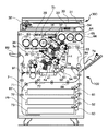
図1は実施例のフルカラー画像形成装置(以下「画像形成装置」と呼ぶ)の概観図である。
[Configuration of Image Forming Apparatus]
FIG. 1 is a schematic view of a full-color image forming apparatus (hereinafter referred to as “image forming apparatus”) of an embodiment.
画像形成装置は、その上部にリーダ300、下部にプリンタ100を有する。なお、プリンタ機能だけではなく、複写機能やファクシミリ機能を併せもつ複合機であってもよい。
The image forming apparatus has a
リーダ300は、スキャナユニット32のランプの光で、原稿台ガラス31上に載置された原稿30を露光し、スキャナユニットを副走査方向に移動する。原稿30からの反射は、スキャナユニット32のミラー、レンズ33を介して、CCDセンサ34に集光する。CCDセンサ34が出力する色分解画像信号は、図示しない増幅回路で増幅され、図示しないビデオ処理ユニットによってRGB画像データに変換され、図示しない画像メモリに格納された後、プリンタ100に出力される。
The
なお、プリンタ100は、リーダ300から出力される画像データを入力するほか、ネットワークを介してコンピュータから画像データを入力し、また、電話回線を介して受信したファクシミリの画像信号も入力する。以下では、代表例として、リーダ300が出力する画像データに対するプリンタ100の動作を説明する。
In addition to inputting image data output from the
プリンタ100は、大別して二つの画像形成部を有する。一つ目は感光ドラム1aを含む第一の画像形成部Sa、二つ目は感光ドラム1bを含む第二の画像形成部Sbである。これら画像形成部Sa、Sbはコストダウンのためにほぼ同じ構成(形状)を有する。つまり、後述する現像器41〜46の構成や形状もほぼ同じであり、これによって現像器41〜46を相互に入れ替えても動作可能である。
The
像担持体としての二つの感光ドラム1a、1bはそれぞれ、図1に示す矢印Aの方向に回転自在に担持されている。感光ドラム1a、1bの周囲にはそれぞれ次の構成が配置されている。露光系として、前露光ランプ11a、11b、コロナ帯電器2a、2b、光学系の露光部3a、3b、並びに、電位センサ12a、12bがある。また、現像系として、回転式現像器の保持部である移動体(現像ロータリ)4a、4bおよび各保持部に色の異なる現像剤を収容する三個の現像器41〜43、44〜46、一次転写ローラ5a、5b、並びに、クリーニング器6a、6bがある。
Each of the two photosensitive drums 1a and 1b serving as an image carrier is supported so as to be rotatable in the direction of arrow A shown in FIG. The following configurations are arranged around the photosensitive drums 1a and 1b, respectively. The exposure system includes pre-exposure lamps 11a and 11b,
なお、高画質化のためには、現像器の数は五個以上であればよいが、実施例1では六個の現像器41〜46を用いる構成とする。そして、現像器が収容するトナーは下記のとおりである。
現像器41はマゼンタトナー
現像器42はシアントナー
現像器43は淡マゼンタトナー
現像器44はイエロートナー
現像器45はブラックトナー
現像器46は淡シアントナー
In order to improve image quality, the number of developing units may be five or more, but in the first embodiment, six developing
濃色および淡色の現像剤(色材)は、分光特性が等しい顔料の量を調整して作成する。つまり、淡マゼンタトナーは、含有する顔料の分光特性はマゼンタトナーと等しいが、顔料の含有量が少ない。同様に、淡シアントナーは、含有する顔料の分光特性はシアントナーと等しいが、顔料の含有量が少ない。また、淡トナーに替えてレッドやグリーンなどの特色トナーの現像器を搭載してもよい。 The dark color and light color developers (coloring materials) are prepared by adjusting the amount of pigment having the same spectral characteristics. That is, the light magenta toner has the same spectral characteristics as the magenta toner, but the pigment content is small. Similarly, the light cyan toner has the same spectral characteristics as that of the cyan toner, but the pigment content is small. Further, a developing device for a special color toner such as red or green may be mounted instead of the light toner.
この他に、金色や銀色などのメタリック系トナーや、蛍光剤を含む蛍光色トナーなど、顔料の分光特性がシアン、マゼンタ、イエロー、ブラックと異なるトナーを収容する現像器(上記の現像器と同形状)を現像ロータリ4a、4bに搭載することも可能である。 In addition to this, a developer containing a toner whose spectral characteristics are different from cyan, magenta, yellow, and black, such as metallic toners such as gold and silver, and fluorescent toner containing a fluorescent agent (same as the above-mentioned developer). Shape) can be mounted on the developing rotary 4a, 4b.
また、各現像器は、トナーとキャリアを混合して用いる二成分現像剤を収容するが、トナーのみからなる一成分現像剤でも問題はない。 Each developing device contains a two-component developer using a mixture of toner and carrier, but there is no problem even with a one-component developer consisting of toner alone.
ここで、マゼンタとシアンに対して濃い色と薄い色を用いるのは、人肌のような色が淡い画像の再現性を飛躍的に向上させるのが狙いである。言い換えれば、色が淡い領域の粒状感を低減することが狙いである。 Here, the purpose of using dark and light colors for magenta and cyan is to drastically improve the reproducibility of images with light colors such as human skin. In other words, the aim is to reduce the graininess of light areas.
画像形成時、感光ドラム1a、1bは、矢印Aの方向に回転し、前露光ランプ11a、11bによって除電された後、帯電器2a、2bによってその表面が一様に帯電させる。一方、露光部3a、3bは、リーダ300から入力される画像データを図示しないレーザ出力部によって光信号に変換する。この光信号(レーザ光E)は、ポリゴンミラー35で反射され、レンズ36および反射ミラー37を経て、感光ドラム1a、1bの表面の露光位置を照射する。これにより、感光ドラム1a、1b上に、トナー色(分解色)ごとに静電潜像を形成する。
At the time of image formation, the photosensitive drums 1a and 1b rotate in the direction of arrow A, and after being neutralized by the pre-exposure lamps 11a and 11b, the surfaces thereof are uniformly charged by the
次に、現像ロータリ4a、4bを回転して現像器41、44を感光ドラム1a、1b上の現像位置に移動した後、現像器41、44を作動(現像器41、44に現像バイアスを印加)して、感光ドラム1a、1b上の静電潜像を現像する。感光ドラム1a、1b上には、樹脂と顔料を基体とする現像剤(トナー)像が形成される。なお、続く現像時は現像器42、45を、さらに続く現像時は現像器43、46によって静電潜像を現像する。
Next, after the developing rotary 4a, 4b is rotated to move the developing
なお、現像器41〜46が収容するトナーは、光学部3a、3bの間、あるいは、光学部3bの横に配置された各色のトナー収納部(ホッパ)61〜66から、現像器内のトナー比率(またはトナー量)を一定に保つように、所定のタイミングで随時補給される。
The toners stored in the developing
感光ドラム1a、1b上に形成されたトナー像はそれぞれ、一次転写ローラ5a、5bによって、転写媒体としての中間転写体(中間転写ベルト)5上に、トナー像が重畳するように順次転写される。このとき、一次転写ローラ5a、5bに一次転写バイアスを印加する。 The toner images formed on the photosensitive drums 1a and 1b are sequentially transferred by the primary transfer rollers 5a and 5b so that the toner images are superimposed on an intermediate transfer member (intermediate transfer belt) 5 as a transfer medium. . At this time, a primary transfer bias is applied to the primary transfer rollers 5a and 5b.
駆動ローラ51および従動ローラ52によって張架され、図に示す矢印Bの方向に駆動される中間転写ベルト5が形成する平面(転写面t)に、感光ドラム1a、1bは接するように配置される。そして、感光ドラム1a、1bと対向する位置に一次転写ローラ5a、5bが配置される。
The photosensitive drums 1a and 1b are arranged in contact with a plane (transfer surface t) formed by the
また、従動ローラ52に対向する位置に、感光ドラム1a、1bから転写した画像の位置ずれおよび濃度を検知するセンサ53を配置する。このセンサ53によって得られる情報に基づき、随時、画像形成部Sa、Sbの画像濃度、トナー補給量、画像書き込みタイミングおよび画像書き込み開始位置などを補正をする制御を行う。
Further, a
二つの画像形成部Sa、Sbそれぞれにおいて、上記の静電潜像の形成、現像、一次転写を三回繰り返せば、中間転写ベルト5上には、六色のトナー像を順次重ねたフルカラートナー像が形成される。その後、中間転写ベルト5上のフルカラートナー像は、記録紙に一括して二次転写される。このとき、二次転写ローラ54に二次転写バイアスを印加する。
In each of the two image forming units Sa and Sb, if the above-described electrostatic latent image formation, development and primary transfer are repeated three times, a full-color toner image in which six color toner images are sequentially superimposed on the
また、駆動ローラ51に対向する位置に転写クリーニング装置50が配置される。転写クリーニング装置50は、二次転写が終了した中間転写ベルト5上に残ったトナーを除去する。駆動ローラ51によって中間転写ベルト5を転写クリーニング装置50の方向へ押しやることで、中間転写ベルト5と転写クリーニング装置50を接触させ、清掃を行うが、清掃終了後、中間転写ベルト5は転写クリーニング装置50より離間する。そして、清掃後の中間転写ベルト5は、次の画像形成に供される。
A
一方、記録紙は記録紙カセット71、72、73または手差しトレイ74から、給紙ローラ81、82、83または84によって一枚ずつ画像形成部に搬送される。そして、レジストローラ85によって、斜行が補正され、給紙タイミングに合わせて二次転写位置へ供給される。
On the other hand, the recording sheets are conveyed one by one from the
フルカラートナー像が転写された記録紙は、搬送ベルト86によって搬送され、熱ローラ定着器9によってトナー像が定着された後、排紙トレイ89または図示しない後処理装置に排出される。
The recording paper on which the full-color toner image has been transferred is conveyed by the
また、記録紙の両面に画像形成する場合は、搬送パス切換ガイド91を駆動して、熱ローラ定着器9を通過した記録紙を、一旦、搬送縦パス7を介して反転パス76に導く。その後、反転ローラ87を逆転して、反転パス76に導かれた際の記録紙の後端を先頭にして、記録紙を反対パス76から退出させて両面搬送パス77へ導く。記録紙は、両面搬送パス77を通過し、両面搬送ローラ88によってレジストローラ85へ送られ、上記の画像形成工程によって、もう一面にフルカラー画像が形成される。
When forming images on both sides of the recording paper, the conveyance
[コントローラ]
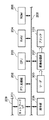
図2は、図1に示す画像形成装置を制御するコントローラの構成例を示すブロック図である。
[controller]
FIG. 2 is a block diagram illustrating a configuration example of a controller that controls the image forming apparatus illustrated in FIG.
コントローラのCPU 203は、RAM 204をワークメモリに利用して、ROM 206に格納されたプログラムを実行し、システムバス208を介して後述する各構成を制御する。
The
操作部205は、ユーザの指示を入力してCPU 203に伝えるとともに、CPU 203の制御に従い装置の状態などを表示する。CPU 203は、操作部205を介して、画像の複写など画像の読み取りを含むジョブをユーザから指示されると、リーダ300を制御して、原稿画像を読み取った画像データを画像処理部207に入力させる。
The
画像処理部207は、受信した画像データにジョブに応じた画像処理を施す。例えば、複写ジョブの場合は、リーダ300から入力された画像データにプリンタ出力に適した画像処理を施し、処理結果の画像データをプリンタ100に出力する。
The
なお、図2には示さないが、システムバス208とリーダ300およびプリンタ100の間は所定のインタフェイスを介して接続されている。従って、CPU 203は、リーダ300およびプリンタ100の動作状態を示すステータス情報を取得し、それらの動作を制御することができる。
Although not shown in FIG. 2, the
また、ネットワークインタフェイス(I/F) 201は、ローカルエリアネットワーク(LAN) などのネットワーク209に接続し、ネットワーク209に接続されたコンピュータやサーバと通信し、様々なコマンドやデータをやり取りする。例えば、外部のコンピュータから記述言語(例えばPDL)で記述された画像データ(PDLデータ)を含む印刷ジョブを受信した場合、CPU 203は、PDLデータをPDL処理部202に供給する。PDL処理部202は、PDLデータを解釈してレンダリングした画像データを画像処理部207に渡す。画像処理部207は、入力される画像データにプリンタ出力に適した画像処理を施し、処理結果の画像データをプリンタ100に出力する。これによって印刷ジョブが実行される。
A network interface (I / F) 201 is connected to a
また、外部のコンピュータからスキャンジョブを受信した場合、CPU 203は、リーダ300に画像を読み取らせる。そして、読み取った画像に対応する画像データを画像処理部207に生成させ、その画像データをネットワークI/F 201を介して、スキャンジョブを発行したコンピュータなどの宛先に送信する。なお、その画像データは、スキャンジョブで指定されたデータフォーマットにする。
When receiving a scan job from an external computer, the
さらに、コントローラ内には、ファクシミリの送受信部、電話回線とのインタフェイスなど、さらに構成が存在するが、ここでは説明を省略する。 Further, there are further configurations in the controller, such as a facsimile transmission / reception unit and an interface with a telephone line, but the description thereof is omitted here.
[画像処理部]
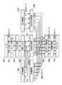
図3は画像処理部207の構成例を示すブロック図である。
[Image processing unit]
FIG. 3 is a block diagram illustrating a configuration example of the
リーダ300が出力する画像データは、多くの場合、一画素当り8ビット(256階調)のRGB画像データである。画像処理部207は、入力したRGB画像データに、シェーディング補正部301で白基準の補正を施し、入力色処理部302で入力マスキング処理を施すことで、CCDの分光特性に起因する色の濁りなどが取り除く。さらに、空間フィルタ303で入力画像データの周波数特性を修正する。
In many cases, the image data output from the
画像処理部207は、上記の処理で得たRGB画像データ、または、PDL処理部202が生成したRGB画像データ(各色8ビット)をRGB色分解部304に入力する。RGB色分解部304は、ダイレクトマッピングにより、RGB画像データをCMYKおよび淡シアンLC、淡マゼンタLMの六色信号(各色10ビット)に色分解する。また、PDL処理部202はCMYK画像データ(各色8ビット)を出力する場合がある。この場合、CMYK画像データをCMYK色分解部308によって各10ビットのCMYKおよびLC、LM信号の六色に色分解する。さらに、外部のコンピュータ(外部装置210)から直接CMYKおよびLC、LM信号が入力されることもある。
The
次に、画像処理部207は、六色の信号を出力ガンマ補正部305に入力する。出力ガンマ補正部305は、各色独立の一次元ルックアップテーブル(1DLUT)を用いて、色分解信号に出力特性の補正(ガンマ補正)を施す。続いて、
Next, the
続いて、中間調処理部306は、プリンタ100が再現可能な階調数および解像度に応じた擬似中間調処理(多値ディザ法)を色分解信号に施す。そして、画像処理部207は、擬似中間調処理されたCMYK信号またはCMYKLCLM信号をプリンタ100に出力する。なお、プリンタ100の階調数および解像度は例えば4ビット、600dpiであるが、これに制限されるものではない。また、擬似中間調処理は公知のスクリーン線処理や誤差拡散処理を用いる。
Subsequently, the
[多値ディザ法]
次に、中間調処理部306が実行する多値ディザ法を説明する。
[Multi-value dither method]
Next, the multi-value dither method executed by the
多値ディザ法は、二値ディザ法を多値に拡張した擬似中間調処理方法である。多値ディザ法はディザマトリクスの升ごとに複数の閾値を有し、その処理結果の画素が取り得る値は複数ある。多値ディザ法には、当然、一画素当り三階調以上の階調数が記録可能な、所謂多階調記録を必要とする。電子写真方式は、PWMによって多階調記録を実現する。 The multi-value dither method is a pseudo halftone processing method obtained by extending the binary dither method to multiple values. The multi-value dither method has a plurality of threshold values for each cell of the dither matrix, and there are a plurality of values that can be taken by the pixel of the processing result. The multi-value dither method naturally requires so-called multi-gradation recording in which the number of gradations of three or more gradations per pixel can be recorded. The electrophotographic method realizes multi-gradation recording by PWM.
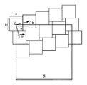
図4は多値ディザ法を説明する図である。 FIG. 4 is a diagram for explaining the multi-value dither method.
中間調処理部306は、各色の処理結果が任意の角度、線数になるように設計したディザマトリクス402を用いる。ディザマトリクス402は、中間調処理部306の出力信号の階調数それぞれに対応する複数段階の閾値マトリクスを有する。実施例の中間調処理部306は、4ビットの信号を出力するので、ディザマトリクス402には、出力信号のレベル1〜15に対応する15個の閾値マトリクスが存在する。
The
中間調処理部306は、色ごとに、入力画像データ401の入力画素の座標に応じてディザマトリクス402の参照すべき升を選択し、それら15個の升に設定された閾値と入力画素値を比較する。具体的には、入力画素値と15個の升の閾値を比較して、入力画素値が閾値以上である升のうち、最も大きいレベルの閾値マトリクスのレベル数を出力信号値にする。また、画素値がどの升の閾値よりも小さい場合は、出力信号値を0とする、出力画像データ403を出力する。
The
次に、スクリーン角およびディザマトリクスの設計方法を説明する。 Next, a screen angle and dither matrix design method will be described.
各色のディザマトリクスは、図5に示すように、a×aの画素からなる基本網点(基本セル)を適当にずらして配置することで、所定のスクリーン角とスクリーン線数をもつ網点を形成することができる。ずらし値(変位ベクトル)をu=(a, b)とすると、得られるスクリーン角θとスクリーン線数LPIは次式によって計算できる。
θ = tan-1(b/a)
LPI = DPI/√(a2 + b2)
ただし、DPIは出力解像度
As shown in FIG. 5, the dither matrix for each color has a halftone dot having a predetermined screen angle and number of screen lines by appropriately shifting basic halftone dots (basic cells) made up of a × a pixels. Can be formed. When the shift value (displacement vector) is u = (a, b), the obtained screen angle θ and the screen line number LPI can be calculated by the following equations.
θ = tan -1 (b / a)
LPI = DPI / √ (a 2 + b 2 )
However, DPI is the output resolution
さらに、網点の一周期に相当する正方閾値マトリクスのサイズNは、変位ベクトルuから次のようになる。
N = LCM(a, b)×(b/a + a/b)
ここで、LCM(a, b)はaとbの最小公倍数
Furthermore, the size N of the square threshold matrix corresponding to one period of halftone dots is as follows from the displacement vector u.
N = LCM (a, b) x (b / a + a / b)
Where LCM (a, b) is the least common multiple of a and b
所望のスクリーン角度、線数のディザマトリクスを実現し、かつ、ハードウェアの負担を軽減する意味で、なるべく小さいマトリクスサイズを用いることが必要になる。 It is necessary to use a matrix size as small as possible in order to realize a dither matrix having a desired screen angle and number of lines and reduce the burden on hardware.
各色に異なるスクリーン角を設定する効果は、各色の位置がずれた場合でも色の一様性を保てること、さらに、モアレ縞の発生を抑えること、などが挙げられる。とくにモアレ縞の発生は、各色のスクリーン角の組み合わせに大きく依存し、広く普及する組み合わせはイエロー0度、シアン(またはマゼンタ)15度、ブラック45度、マゼンタ(またはシアン)75度などである。 The effect of setting a different screen angle for each color includes maintaining the uniformity of the color even when the position of each color is shifted, and further suppressing the occurrence of moire fringes. In particular, the occurrence of moire fringes greatly depends on the combination of the screen angles of the respective colors, and the widespread combinations are yellow 0 degree, cyan (or magenta) 15 degrees, black 45 degrees, magenta (or cyan) 75 degrees, and the like.
図6は各色のスクリーン角、線数を示す図である。各色のスクリーン角、線数は次のようにする。
シアン、ライトシアンは71度、189線
マゼンダ、ライトマゼンダは18度、189線
イエローは0度、150線
ブラックは45度、212線
FIG. 6 is a diagram showing the screen angle and the number of lines of each color. The screen angle and the number of lines for each color are as follows.
Cyan,
さらに、シアン、マゼンダ、イエロー、ブラックは、一般に用いられる階調値を増やす方向にドットを成長させるマトリクス(ここでは「通常スクリーン」と呼ぶ)を使用する。また、淡色版であるライトシアンとライトマゼンダは、マトリクス内のドット面積を増やす方向にドットを成長させるマトリクス(ここでは「平坦化スクリーン」と呼ぶ)を使用する。 Further, cyan, magenta, yellow, and black use a matrix (herein referred to as “normal screen”) in which dots are grown in a direction that increases a generally used gradation value. Light cyan and light magenta, which are light-colored plates, use a matrix (referred to herein as a “flattened screen”) that grows dots in a direction that increases the dot area in the matrix.
次に、通常スクリーンと平坦化スクリーンについて説明する。 Next, the normal screen and the flattening screen will be described.
図4と図7はそれぞれ、同一のスクリーン角、線数における、通常スクリーンと平坦化スクリーンのディザマトリクスを示す。なお、両図とも入力画像データ401は同一である。
4 and 7 show the dither matrix of the normal screen and the flattened screen, respectively, at the same screen angle and number of lines. In both figures, the
図4に示す通常スクリーンは、レベルが異なる閾値マトリクスの同じ位置の升間では、レベルの増加に伴い、その値が増加するように閾値が与えられる(以下「レベル方向に成長」と呼ぶ)。そして、ある升の閾値をレベル方向に成長した後、続けて、隣接位置の升の閾値をレベル方向に成長する。従って、図4の右下に示すディザマトリクス402の二行目に相当する出力信号値のように、出力信号値は基本セル内でドットを集中する(狭い範囲に濃度が高いドットを形成する)傾向を示し、基本セルの周期で強くパターンが現れる。なお、このような閾値の設定方法を「閾値の成長方法」と呼ぶ場合がある。
In the normal screen shown in FIG. 4, a threshold is given so that the value increases as the level increases between the same positions in the threshold matrix having different levels (hereinafter referred to as “grow in the level direction”). Then, after a certain wrinkle threshold value is grown in the level direction, a wrinkle threshold value at an adjacent position is continuously grown in the level direction. Therefore, the output signal value concentrates dots within the basic cell (forms a high-density dot in a narrow range) like the output signal value corresponding to the second row of the
一方、図7に示す平坦化スクリーンは、ディザマトリクス402内においてドット面積を増やすように閾値が与えられている。通常スクリーンと同様に、レベルが異なる閾値マトリクスの同じ位置の升間では閾値をレベル方向に成長させる。そして、ある位置の升の閾値をレベル方向に成長するとともに、隣接位置の升の閾値もレベル方向に成長し、さらに隣接する位置の升の閾値もレベル方向に成長する。従って、図7の右下に示すディザマトリクス402の二行目に相当する出力信号値のように、出力信号値は基本セル内でドットを拡散する(広い範囲に濃度が低いドットを形成する)傾向を示し、通常スクリーンに比べて基本セルの周期のパターンは現れにくい。
On the other hand, the flattening screen shown in FIG. 7 is given a threshold value so as to increase the dot area in the
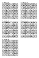
図8Aから8Cはスクリーン角71度、スクリーン線数189線の通常スクリーンのディザマトリクスの一例を示す図で、シアンのディザマトリクスの一例である。 8A to 8C are diagrams showing an example of a normal screen dither matrix having a screen angle of 71 degrees and a screen line number of 189 lines, and are examples of a cyan dither matrix.
図9Aから9Cはスクリーン角71度、スクリーン線数189線の平坦化スクリーンのディザマトリクスの一例を示す図で、ライトシアンのディザマトリクスの一例である。 FIGS. 9A to 9C are diagrams illustrating an example of a dither matrix of a flattening screen having a screen angle of 71 degrees and a screen line number of 189 lines, and are examples of a light cyan dither matrix.
図10Aから10Cはスクリーン角18度、スクリーン線数189線の通常スクリーンのディザマトリクスの一例を示す図で、マゼンダのディザマトリクスの一例である。 FIGS. 10A to 10C are diagrams showing an example of a normal screen dither matrix having a screen angle of 18 degrees and a screen line number of 189 lines, which is an example of a magenta dither matrix.
図11Aから11Cはスクリーン角18度、スクリーン線数189線の平坦化スクリーンのディザマトリクスの一例を示す図で、ライトマゼンダのディザマトリクスの一例である。 FIGS. 11A to 11C are diagrams illustrating an example of a dither matrix of a flattening screen having a screen angle of 18 degrees and a screen line number of 189 lines, and are examples of a light magenta dither matrix.
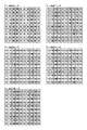
図12はスクリーン角0度、スクリーン線数150線の通常スクリーンのディザマトリクスの一例を示す図で、イエローのディザマトリクスの一例である。 FIG. 12 is a diagram illustrating an example of a normal screen dither matrix having a screen angle of 0 degrees and a screen line number of 150 lines, and is an example of a yellow dither matrix.
図13はスクリーン角45度、スクリーン線数212線の通常スクリーンのディザマトリクスの一例を示す図で、ブラックのディザマトリクスの一例である。 FIG. 13 is a diagram showing an example of a normal screen dither matrix having a screen angle of 45 degrees and a screen line number of 212 lines, and is an example of a black dither matrix.
上記の平坦化スクリーンの閾値マトリクスはすべて、閾値の小さい順に、レベル1の閾値マトリクスから升を埋め、次のレベルのマトリクスに移り、レベル方向に成長する形態を有する。つまり、階調変化がないべたの入力画像データ401に対して、常に、出力画像データ403の最大値と最小値のレベル差が1以下になるように設計されていて、基本セル周期のパターンはほぼ現れない。なお、べたの入力画像データ401に対して、上記レベル差が2以上になるディザマトリクスを設計したとしても、閾値マトリクス全体の閾値が成長するようなディザマトリクスであればよい。
All of the threshold matrixes of the above-described flattening screens have a form in which the wrinkles are filled from the threshold matrix of
以下、本発明にかかる実施例2の画像処理を説明する。なお、実施例2において、実施例1と略同様の構成については、同一符号を付して、その詳細説明を省略する。 The image processing according to the second embodiment of the present invention will be described below. Note that the same reference numerals in the second embodiment denote the same parts as in the first embodiment, and a detailed description thereof will be omitted.
図14は実施例2の画像形成装置の画像処理部207の構成例を示すブロック図である。
FIG. 14 is a block diagram illustrating a configuration example of the
実施例2の画像形成装置は、ライトシアンとライトマゼンダを使用しないシアン、マゼンダ、イエロー、ブラックの四色システムとして動作する。中間調処理部306は、他の三色に比べて明度が高いイエローに、図15に示すブラックと同一のスクリーン角、線数をもつ平坦化スクリーンのディザマトリクスを用いて擬似中間調処理する。なお、シアン、マゼンダ、ブラックについては実施例1と同様の通常スクリーンを使用する。すなわち、実施例2において使用する色ごとのスクリーン角、線数は次のようになる。
シアンは71度、189線
マゼンダは18度、189線
イエロー、ブラックは45度、212線
The image forming apparatus according to the second embodiment operates as a four-color system of cyan, magenta, yellow, and black that does not use light cyan and light magenta. The
なお、イエローのディザマトリクスは、ブラックと同一のスクリーン角、線数に限らず、シアンやマゼンダなど他の色と同一のスクリーン角、線数と同一の平坦化スクリーンにしてもよい。 The yellow dither matrix is not limited to the same screen angle and number of lines as black, but may be a flat screen having the same screen angle and number of lines as other colors such as cyan and magenta.
以下、本発明にかかる実施例2の画像処理を説明する。なお、実施例2において、実施例1と略同様の構成については、同一符号を付して、その詳細説明を省略する。 The image processing according to the second embodiment of the present invention will be described below. Note that the same reference numerals in the second embodiment denote the same parts as in the first embodiment, and a detailed description thereof will be omitted.
図16は実施例3の画像形成装置の画像処理部207の構成例を示すブロック図である。
FIG. 16 is a block diagram illustrating a configuration example of the
実施例3の画像形成装置は、ライトシアンとライトマゼンダの代りに、レッドRとグリーンGを使用する六色システムとして動作する。従って、RGB色分解部304は、RGB信号をCMYK信号とR、G信号に分解する。また、CMYK色分解部308は、CMYK信号をCMYK信号とR、G信号に分解する。中間調処理部306は、シアンの補色であるレッドを、図9Aから9Cに示すライトシアンと同一のスクリーン角、線数をもつ平坦化スクリーンのディザマトリクスを用いて擬似中間調処理する。また、マゼンダの補色であるグリーンを、図11Aから11Cに示すライトマゼンダと同一のスクリーン角、線数をもつ平坦化スクリーンのディザマトリクスを用いて擬似中間調処理する。なお、シアン、マゼンダ、イエロー、ブラックについては実施例1と同様の通常スクリーンを使用する。すなわち、実施例2において使用する色ごとのスクリーン角、線数は次のようになる。
シアン、レッドは71度、189線
マゼンダ、グリーンは18度、189線
イエローは0度、150線
ブラックは45度、212線
The image forming apparatus according to the third exemplary embodiment operates as a six-color system that uses red R and green G instead of light cyan and light magenta. Therefore, the RGB
Cyan, Red are 71 degrees, 189 lines Magenta, Green are 18 degrees, 189 lines Yellow are 0 degrees, 150 lines Black are 45 degrees, 212 lines
上記では、レッドのスクリーン角、線数をシアンと同一とし、グリーンのスクリーン角、線数をマゼンダと同一とした。さらに、イエローの補色であるブルーに、イエローと同一のスクリーン角、線数をもつ平坦化スクリーンを適用することも有効である。 In the above, the red screen angle and the number of lines are the same as cyan, and the green screen angle and the number of lines are the same as magenta. Furthermore, it is also effective to apply a flattening screen having the same screen angle and number of lines as that of yellow, which is a complementary color of yellow.
[変形例]
有限の解像度を有する画像形成装置において、ディザパターンのスクリーン角には制約があり、有理正接の角度にスクリーン角を設定することが一般的である。しかし、画素位置に応じてレーザビームの点灯位置を最適化して、任意の無理正接の角度にスクリーン角を設定することもできる。また、階調数を確保するために、基本セルをサブマトリクス化するなどしてディザマトリクスを作成することもできる。
[Modification]
In an image forming apparatus having a finite resolution, the screen angle of a dither pattern is limited, and the screen angle is generally set to a rational tangent angle. However, the screen angle can be set to an arbitrary tangent angle by optimizing the laser beam lighting position in accordance with the pixel position. In order to secure the number of gradations, a dither matrix can be created by sub-matrixing the basic cells.
また、上記の実施例における、各色のディザマトリクスのスクリーン角、線数は上記に限定されるものではない。 Further, the screen angle and the number of lines of the dither matrix for each color in the above embodiment are not limited to the above.
上記の実施例において、色材の構成としてシアン、マゼンダ、イエロー、ブラックの基本色を使用する四色システム、さらにライトシアンとライトマゼンタ、または、レッドとグリーンを使用する六色システムを説明した。しかし、その他の複数種の色材を用いるシステムにも本発明を適用することができる。例えば、ブラックと同一色相かつ高明度のライトブラック(すなわちグレイ)の色材を加えた五色や七色システムなど、同一色相で明度が異なる濃淡色材の組み合わせを用いるシステムであれば構わない。 In the above embodiment, the four-color system using the basic colors of cyan, magenta, yellow, and black as the color material configuration, and the six-color system using light cyan and light magenta or red and green have been described. However, the present invention can also be applied to systems using other types of color materials. For example, a system using a combination of light and dark color materials having the same hue and different lightness, such as a five-color or seven-color system in which a light black (that is, gray) color material having the same hue and high brightness as black is added.
このように、同一色相の濃淡トナーを用いる場合に、濃色版と淡色版に同一のスクリーン角、線数で、成長方法が異なるディザマトリクスを用いることで、五色以上のシステムにおいて、モアレや干渉縞の発生を最小限に防ぐことができる。さらに、全色をディザ法で中間調処理するので、誤差拡散などのFMスクリーン系に特有のノイズが発生しない。また、明度の低い淡色版に低い周波数特性のディザパターンを適用し、ドットの集中成長を防ぐことで、ざらつきなどが視覚的に目立たないようにする。 In this way, when dark and light toners of the same hue are used, moiré and interference can be achieved in a system of five or more colors by using dither matrices with the same screen angle and number of lines and different growth methods for the dark and light color plates. The generation of streaks can be minimized. Furthermore, since all colors are halftone processed by the dither method, noise specific to the FM screen system such as error diffusion does not occur. In addition, a dither pattern having a low frequency characteristic is applied to a light color plate with low lightness to prevent concentrated growth of dots so that roughness and the like are not visually noticeable.
シアン、マゼンダ、イエロー、ブラックの四色システムにおいては、明度が高いイエローについて、他の三色のどれかと同じスクリーン角、線数をもち、成長方法が異なるディザパターンを用いる。これによって、従来のディザ法を用いた四色システム以上にモアレを低減することができる。 In the four-color system of cyan, magenta, yellow, and black, a dither pattern that has the same screen angle and number of lines as that of any of the other three colors and has a different growth method is used for yellow with high brightness. As a result, the moire can be reduced more than the four-color system using the conventional dither method.
シアン、マゼンダ、イエローと補色関係にあるレッド、グリーン、ブルーの色材を用いる場合、補色と同一のスクリーン角、線数をもち、成長方法が異なるディザパターンを用いることで、五色以上のシステムにおいてモアレの発生を最小限に留めることができる。 When using red, green, and blue colorants that are complementary to cyan, magenta, and yellow, use a dither pattern that has the same screen angle and number of lines as the complementary colors, but with a different growth method. Generation of moiré can be minimized.
[他の実施例]
なお、本発明は、複数の機器(例えばホストコンピュータ、インタフェイス機器、リーダ、プリンタなど)から構成されるシステムに適用しても、一つの機器からなる装置(例えば、複写機、ファクシミリ装置など)に適用してもよい。
[Other embodiments]
Note that the present invention can be applied to a system including a plurality of devices (for example, a host computer, an interface device, a reader, and a printer), and a device (for example, a copying machine and a facsimile device) including a single device. You may apply to.
また、本発明の目的は、上記実施例の機能を実現するソフトウェアを記録した記憶媒体(記録媒体)をシステムまたは装置に供給し、そのシステムまたは装置のコンピュータ(CPUやMPU)が前記ソフトウェアを実行することでも達成される。この場合、記憶媒体から読み出されたソフトウェア自体が上記実施例の機能を実現することになり、そのソフトウェアを記憶した記憶媒体は本発明を構成する。 Another object of the present invention is to supply a storage medium (recording medium) that records software for realizing the functions of the above-described embodiments to a system or apparatus, and a computer (CPU or MPU) of the system or apparatus executes the software. Is also achieved. In this case, the software itself read from the storage medium realizes the functions of the above-described embodiments, and the storage medium storing the software constitutes the present invention.
また、前記ソフトウェアの実行により上記機能が実現されるだけでなく、そのソフトウェアの指示により、コンピュータ上で稼働するオペレーティングシステム(OS)などが実際の処理の一部または全部を行い、それによって上記機能が実現される場合も含む。 In addition, the above functions are not only realized by the execution of the software, but an operating system (OS) running on a computer performs part or all of the actual processing according to the instructions of the software, and thereby the above functions This includes the case where is realized.
また、前記ソフトウェアがコンピュータに接続された機能拡張カードやユニットのメモリに書き込まれ、そのソフトウェアの指示により、前記カードやユニットのCPUなどが実際の処理の一部または全部を行い、それによって上記機能が実現される場合も含む。 In addition, the software is written in a function expansion card or unit memory connected to the computer, and the CPU of the card or unit performs part or all of the actual processing according to instructions of the software, thereby This includes the case where is realized.
本発明を前記記憶媒体に適用する場合、その記憶媒体には、先に説明したフローチャートに対応するソフトウェアが格納される。 When the present invention is applied to the storage medium, the storage medium stores software corresponding to the flowchart described above.
Claims (12)
前記色材に対応する画像データに多値ディザ処理を施す中間調処理手段とを有し、
前記中間調処理手段は、同色相で明度が異なる濃および淡色材に対応する画像データそれぞれに、同一のスクリーン角、線数をもち、閾値の設定方法が異なるディザマトリクスを適用することを特徴とする画像処理装置。 Color separation means for color-separating input image data into image data corresponding to a color material;
Halftone processing means for performing multi-value dither processing on the image data corresponding to the color material,
The halftone processing means applies a dither matrix having the same screen angle and number of lines and different threshold setting methods to each of image data corresponding to dark and light color materials having the same hue and different brightness. An image processing apparatus.
前記色材に対応する画像データに多値ディザ処理を施す中間調処理手段とを有し、
前記中間調処理手段は、イエローの色材に対応する画像データに、他の色材の画像データと同一のスクリーン角、線数をもち、閾値の設定方法が異なるディザマトリクスを適用することを特徴とする画像処理装置。 Color separation means for color-separating input image data into image data corresponding to a color material;
Halftone processing means for performing multi-value dither processing on the image data corresponding to the color material,
The halftone processing unit applies a dither matrix having the same screen angle and number of lines as the image data of the other color materials and a different threshold setting method to the image data corresponding to the yellow color material. An image processing apparatus.
前記色材に対応する画像データに多値ディザ処理を施す中間調処理手段とを有し、
前記中間調処理手段は、補色関係にある色材に対応する画像データそれぞれに、同一のスクリーン角、線数をもち、閾値の設定方法が異なるディザマトリクスを適用することを特徴とする画像処理装置。 Color separation means for color-separating input image data into image data corresponding to a color material;
Halftone processing means for performing multi-value dither processing on the image data corresponding to the color material,
The halftone processing unit applies a dither matrix having the same screen angle and number of lines and different threshold setting methods to each of image data corresponding to color materials having a complementary color relationship. .
前記多値ディザ処理は、同色相で明度が異なる濃および淡色材に対応する画像データそれぞれに、同一のスクリーン角、線数をもち、閾値の設定方法が異なるディザマトリクスを適用することを特徴とする画像処理方法。 An image processing method for color-separating input image data into image data corresponding to a color material, and performing multi-value dither processing on the image data corresponding to the color material,
The multi-value dither processing is characterized in that a dither matrix having the same screen angle and number of lines and different threshold setting methods is applied to image data corresponding to dark and light color materials having the same hue and different brightness. Image processing method.
前記多値ディザ処理は、イエローの色材に対応する画像データに、他の色材の画像データと同一のスクリーン角、線数をもち、閾値の設定方法が異なるディザマトリクスを適用することを特徴とする画像処理方法。 An image processing method for color-separating input image data into image data corresponding to a color material, and performing multi-value dither processing on the image data corresponding to the color material,
In the multi-value dither processing, a dither matrix having the same screen angle and number of lines as the image data of other color materials and a different threshold setting method is applied to the image data corresponding to the yellow color material. An image processing method.
前記多値ディザ処理は、補色関係にある色材に対応する画像データそれぞれに、同一のスクリーン角、線数をもち、閾値の設定方法が異なるディザマトリクスを適用することを特徴とする画像処理方法。 An image processing method for color-separating input image data into image data corresponding to a color material, and performing multi-value dither processing on the image data corresponding to the color material,
In the multi-value dithering process, a dither matrix having the same screen angle and number of lines and different threshold setting methods is applied to each of image data corresponding to color materials having a complementary color relationship. .
Priority Applications (2)
| Application Number | Priority Date | Filing Date | Title |
|---|---|---|---|
| JP2005241559A JP2007060149A (en) | 2005-08-23 | 2005-08-23 | Image processor and its method |
| US11/466,221 US20070046961A1 (en) | 2005-08-23 | 2006-08-22 | Image processing apparatus and method therefor |
Applications Claiming Priority (1)
| Application Number | Priority Date | Filing Date | Title |
|---|---|---|---|
| JP2005241559A JP2007060149A (en) | 2005-08-23 | 2005-08-23 | Image processor and its method |
Publications (2)
| Publication Number | Publication Date |
|---|---|
| JP2007060149A true JP2007060149A (en) | 2007-03-08 |
| JP2007060149A5 JP2007060149A5 (en) | 2008-10-02 |
Family
ID=37803629
Family Applications (1)
| Application Number | Title | Priority Date | Filing Date |
|---|---|---|---|
| JP2005241559A Pending JP2007060149A (en) | 2005-08-23 | 2005-08-23 | Image processor and its method |
Country Status (2)
| Country | Link |
|---|---|
| US (1) | US20070046961A1 (en) |
| JP (1) | JP2007060149A (en) |
Cited By (5)
| Publication number | Priority date | Publication date | Assignee | Title |
|---|---|---|---|---|
| JP2010081362A (en) * | 2008-09-26 | 2010-04-08 | Fuji Xerox Co Ltd | Image processing apparatus and image processing program |
| JP2011033775A (en) * | 2009-07-31 | 2011-02-17 | Kyocera Mita Corp | Image forming apparatus |
| JP2011061400A (en) * | 2009-09-09 | 2011-03-24 | Fuji Xerox Co Ltd | Color processor, image forming apparatus, program, and recording medium |
| DE202007019236U1 (en) | 2007-11-02 | 2011-11-09 | Valentina Anzupowa | Color splitter imager group with partially opaque mirrors and mosaic color filters |
| US8736903B2 (en) | 2011-03-08 | 2014-05-27 | Fuji Xerox Co., Ltd. | Image processing apparatus, image forming apparatus, and computer readable medium storing program |
Families Citing this family (15)
| Publication number | Priority date | Publication date | Assignee | Title |
|---|---|---|---|---|
| JP2005286999A (en) * | 2004-03-05 | 2005-10-13 | Fuji Photo Film Co Ltd | Allocation method of threshold matrix |
| JP4143560B2 (en) * | 2004-03-05 | 2008-09-03 | 富士フイルム株式会社 | Method and apparatus for creating threshold matrix |
| JP4241632B2 (en) * | 2005-01-25 | 2009-03-18 | 富士フイルム株式会社 | Color plate creation threshold value matrix creation method, color image reproduction method, color image separation creation device, and threshold matrix |
| JP4380602B2 (en) | 2005-07-27 | 2009-12-09 | キヤノン株式会社 | Image forming apparatus and control method thereof |
| JP4412733B2 (en) * | 2005-08-02 | 2010-02-10 | キヤノン株式会社 | Image processing apparatus and method, and computer program and storage medium |
| US8064112B1 (en) * | 2007-05-20 | 2011-11-22 | Opaltone Australasia Pty. Ltd. | Color separation and reproduction method to control a printing process |
| JP5149690B2 (en) * | 2008-05-02 | 2013-02-20 | キヤノン株式会社 | Image processing apparatus, image processing method, and image processing program |
| JP5180670B2 (en) * | 2008-05-07 | 2013-04-10 | キヤノン株式会社 | Image processing apparatus and image processing method |
| JP2011082746A (en) * | 2009-10-06 | 2011-04-21 | Canon Inc | Image processing apparatus |
| JP5424820B2 (en) * | 2009-11-06 | 2014-02-26 | キヤノン株式会社 | Image forming apparatus, image forming method, and program |
| JP5371904B2 (en) * | 2010-01-27 | 2013-12-18 | 京セラドキュメントソリューションズ株式会社 | Image forming apparatus |
| JP5898507B2 (en) * | 2012-01-27 | 2016-04-06 | キヤノン株式会社 | Image processing apparatus and image processing method |
| JP6335013B2 (en) * | 2014-04-30 | 2018-05-30 | キヤノン株式会社 | Image forming apparatus |
| EP3224765B1 (en) * | 2014-11-26 | 2022-07-20 | HP Indigo B.V. | Rosette-free printing |
| CN109978111A (en) * | 2019-03-13 | 2019-07-05 | 杭州百伴生物技术有限公司 | Matrix two-dimensional code, its generation, coding/decoding method and its equipment |
Citations (9)
| Publication number | Priority date | Publication date | Assignee | Title |
|---|---|---|---|---|
| JPH09191411A (en) * | 1996-01-09 | 1997-07-22 | Canon Inc | Image forming device |
| JPH1127552A (en) * | 1997-05-07 | 1999-01-29 | Seiko Epson Corp | Gradation processor and gradation processing method of color image |
| JP2000196885A (en) * | 1998-12-25 | 2000-07-14 | Toshiba Tec Corp | Method and device for image processing |
| JP2000299783A (en) * | 1999-02-08 | 2000-10-24 | Sharp Corp | Image processing method and device |
| JP2001018454A (en) * | 1999-07-05 | 2001-01-23 | Dainippon Screen Mfg Co Ltd | Method for recording halftone dot image |
| JP2002049191A (en) * | 2000-08-02 | 2002-02-15 | Konica Corp | Image forming device |
| JP2003326765A (en) * | 2002-05-16 | 2003-11-19 | Fuji Photo Film Co Ltd | Method and apparatus for dot imaging |
| JP2004025621A (en) * | 2002-06-25 | 2004-01-29 | Canon Inc | Dot gradation expression method, computer program, and computer readable storage medium |
| JP2004058390A (en) * | 2002-07-26 | 2004-02-26 | Fuji Photo Film Co Ltd | Method, system and program for reproducing color image |
Family Cites Families (10)
| Publication number | Priority date | Publication date | Assignee | Title |
|---|---|---|---|---|
| JP2859296B2 (en) * | 1989-06-01 | 1999-02-17 | キヤノン株式会社 | Image reproducing method and apparatus |
| US5370976A (en) * | 1992-05-22 | 1994-12-06 | Williamson Printing Corporation | Metallic color printing process |
| JP4386216B2 (en) * | 1999-03-09 | 2009-12-16 | キヤノン株式会社 | Color printing system and control method thereof |
| US6906825B1 (en) * | 1999-06-14 | 2005-06-14 | Toshiba Tec Kabushiki Kaisha | Image processor and color image processor |
| US6819902B2 (en) * | 2002-03-29 | 2004-11-16 | Canon Kabushiki Kaisha | Image forming apparatus with interchangeable developing devices |
| JP4560379B2 (en) * | 2004-03-18 | 2010-10-13 | 株式会社リコー | Image forming apparatus, image forming method, program, and recording medium |
| JP4393328B2 (en) * | 2004-09-22 | 2010-01-06 | キヤノン株式会社 | Image processing apparatus and method |
| US20070002410A1 (en) * | 2005-06-30 | 2007-01-04 | Majewicz Peter I | Hybrid halftoning |
| JP4380602B2 (en) * | 2005-07-27 | 2009-12-09 | キヤノン株式会社 | Image forming apparatus and control method thereof |
| JP4412733B2 (en) * | 2005-08-02 | 2010-02-10 | キヤノン株式会社 | Image processing apparatus and method, and computer program and storage medium |
-
2005
- 2005-08-23 JP JP2005241559A patent/JP2007060149A/en active Pending
-
2006
- 2006-08-22 US US11/466,221 patent/US20070046961A1/en not_active Abandoned
Patent Citations (9)
| Publication number | Priority date | Publication date | Assignee | Title |
|---|---|---|---|---|
| JPH09191411A (en) * | 1996-01-09 | 1997-07-22 | Canon Inc | Image forming device |
| JPH1127552A (en) * | 1997-05-07 | 1999-01-29 | Seiko Epson Corp | Gradation processor and gradation processing method of color image |
| JP2000196885A (en) * | 1998-12-25 | 2000-07-14 | Toshiba Tec Corp | Method and device for image processing |
| JP2000299783A (en) * | 1999-02-08 | 2000-10-24 | Sharp Corp | Image processing method and device |
| JP2001018454A (en) * | 1999-07-05 | 2001-01-23 | Dainippon Screen Mfg Co Ltd | Method for recording halftone dot image |
| JP2002049191A (en) * | 2000-08-02 | 2002-02-15 | Konica Corp | Image forming device |
| JP2003326765A (en) * | 2002-05-16 | 2003-11-19 | Fuji Photo Film Co Ltd | Method and apparatus for dot imaging |
| JP2004025621A (en) * | 2002-06-25 | 2004-01-29 | Canon Inc | Dot gradation expression method, computer program, and computer readable storage medium |
| JP2004058390A (en) * | 2002-07-26 | 2004-02-26 | Fuji Photo Film Co Ltd | Method, system and program for reproducing color image |
Cited By (6)
| Publication number | Priority date | Publication date | Assignee | Title |
|---|---|---|---|---|
| DE202007019236U1 (en) | 2007-11-02 | 2011-11-09 | Valentina Anzupowa | Color splitter imager group with partially opaque mirrors and mosaic color filters |
| JP2010081362A (en) * | 2008-09-26 | 2010-04-08 | Fuji Xerox Co Ltd | Image processing apparatus and image processing program |
| US8385635B2 (en) | 2008-09-26 | 2013-02-26 | Fuji Xerox Co., Ltd. | Image processing apparatus for performing AM screen processing and FM screen processing, image processing method, computer-readable medium |
| JP2011033775A (en) * | 2009-07-31 | 2011-02-17 | Kyocera Mita Corp | Image forming apparatus |
| JP2011061400A (en) * | 2009-09-09 | 2011-03-24 | Fuji Xerox Co Ltd | Color processor, image forming apparatus, program, and recording medium |
| US8736903B2 (en) | 2011-03-08 | 2014-05-27 | Fuji Xerox Co., Ltd. | Image processing apparatus, image forming apparatus, and computer readable medium storing program |
Also Published As
| Publication number | Publication date |
|---|---|
| US20070046961A1 (en) | 2007-03-01 |
Similar Documents
| Publication | Publication Date | Title |
|---|---|---|
| JP2007060149A (en) | Image processor and its method | |
| US7990589B2 (en) | Image processing apparatus and method therefor | |
| JP5137451B2 (en) | Image forming apparatus | |
| US7626741B2 (en) | Image processing method and apparatus thereof | |
| US7746504B2 (en) | Image forming apparatus and method which perform smoothing processing | |
| KR100905630B1 (en) | Image forming apparatus | |
| US5337167A (en) | Halftone image forming apparatus including density based dot enlargement | |
| JP2007043306A (en) | Image processing apparatus and processing method | |
| JP2007049338A (en) | Apparatus, method and program for processing color image | |
| JP2006106713A (en) | Electrophotographic image recording apparatus and image processing apparatus | |
| JP2008107803A (en) | Image forming apparatus and image forming method | |
| JP2009037138A (en) | Image forming apparatus, color image forming apparatus | |
| JP4991377B2 (en) | Image forming apparatus | |
| JP2008154115A (en) | Image forming apparatus and correction method | |
| JP2000108406A (en) | Imaging apparatus and control method therefor | |
| JP3469927B2 (en) | Color unevenness prevention gradation processing device | |
| JP2005189715A (en) | Image forming apparatus | |
| JP4319182B2 (en) | Image forming method, screen set, and image forming apparatus | |
| JPH09284553A (en) | Medium tone processing method | |
| JP4058795B2 (en) | Image processing apparatus and image processing method | |
| JP2005252323A (en) | Apparatus and method for forming color image | |
| JP2005202027A (en) | Image forming apparatus | |
| JP2006166176A (en) | Image processor | |
| JP2005277657A (en) | Image processor, image forming device, and its control method | |
| JP2615271B2 (en) | Gradation processing method |
Legal Events
| Date | Code | Title | Description |
|---|---|---|---|
| A521 | Request for written amendment filed |
Free format text: JAPANESE INTERMEDIATE CODE: A523 Effective date: 20080819 |
|
| A621 | Written request for application examination |
Free format text: JAPANESE INTERMEDIATE CODE: A621 Effective date: 20080819 |
|
| A977 | Report on retrieval |
Free format text: JAPANESE INTERMEDIATE CODE: A971007 Effective date: 20091102 |
|
| A131 | Notification of reasons for refusal |
Free format text: JAPANESE INTERMEDIATE CODE: A131 Effective date: 20091106 |
|
| A131 | Notification of reasons for refusal |
Free format text: JAPANESE INTERMEDIATE CODE: A131 Effective date: 20100118 |
|
| A521 | Request for written amendment filed |
Free format text: JAPANESE INTERMEDIATE CODE: A523 Effective date: 20100309 |
|
| A131 | Notification of reasons for refusal |
Free format text: JAPANESE INTERMEDIATE CODE: A131 Effective date: 20100712 |
|
| A02 | Decision of refusal |
Free format text: JAPANESE INTERMEDIATE CODE: A02 Effective date: 20110225 |