JP2012059262A - Method and apparatus for collecting process control data - Google Patents
Method and apparatus for collecting process control data Download PDFInfo
- Publication number
- JP2012059262A JP2012059262A JP2011191667A JP2011191667A JP2012059262A JP 2012059262 A JP2012059262 A JP 2012059262A JP 2011191667 A JP2011191667 A JP 2011191667A JP 2011191667 A JP2011191667 A JP 2011191667A JP 2012059262 A JP2012059262 A JP 2012059262A
- Authority
- JP
- Japan
- Prior art keywords
- data
- process control
- parameter
- exemplary
- electronic device
- Prior art date
- Legal status (The legal status is an assumption and is not a legal conclusion. Google has not performed a legal analysis and makes no representation as to the accuracy of the status listed.)
- Pending
Links
- 238000004886 process control Methods 0.000 title claims abstract description 238
- 238000000034 method Methods 0.000 title claims abstract description 120
- 238000005070 sampling Methods 0.000 claims abstract description 26
- 238000005259 measurement Methods 0.000 claims abstract description 21
- 238000004519 manufacturing process Methods 0.000 claims abstract description 11
- 230000004044 response Effects 0.000 claims abstract description 6
- 238000012546 transfer Methods 0.000 claims description 39
- 239000011159 matrix material Substances 0.000 claims description 6
- 230000008569 process Effects 0.000 description 61
- 238000004891 communication Methods 0.000 description 60
- 238000012805 post-processing Methods 0.000 description 37
- 238000004458 analytical method Methods 0.000 description 11
- 230000006870 function Effects 0.000 description 11
- 238000010586 diagram Methods 0.000 description 10
- 238000001824 photoionisation detection Methods 0.000 description 9
- 238000012545 processing Methods 0.000 description 9
- 230000000875 corresponding effect Effects 0.000 description 7
- 230000003287 optical effect Effects 0.000 description 6
- 230000009471 action Effects 0.000 description 5
- 230000010354 integration Effects 0.000 description 4
- 238000003491 array Methods 0.000 description 3
- 230000008859 change Effects 0.000 description 3
- 238000013500 data storage Methods 0.000 description 3
- 230000001360 synchronised effect Effects 0.000 description 3
- 238000003745 diagnosis Methods 0.000 description 2
- 230000003993 interaction Effects 0.000 description 2
- 230000000737 periodic effect Effects 0.000 description 2
- 230000002085 persistent effect Effects 0.000 description 2
- 239000000126 substance Substances 0.000 description 2
- 229920001131 Pulp (paper) Polymers 0.000 description 1
- 238000007792 addition Methods 0.000 description 1
- 238000013459 approach Methods 0.000 description 1
- 230000006399 behavior Effects 0.000 description 1
- 230000005540 biological transmission Effects 0.000 description 1
- 238000009530 blood pressure measurement Methods 0.000 description 1
- 238000009529 body temperature measurement Methods 0.000 description 1
- 230000003139 buffering effect Effects 0.000 description 1
- 238000004364 calculation method Methods 0.000 description 1
- 230000000295 complement effect Effects 0.000 description 1
- 238000012790 confirmation Methods 0.000 description 1
- 230000002596 correlated effect Effects 0.000 description 1
- 230000000694 effects Effects 0.000 description 1
- 230000007613 environmental effect Effects 0.000 description 1
- 230000003203 everyday effect Effects 0.000 description 1
- 239000012530 fluid Substances 0.000 description 1
- 239000007788 liquid Substances 0.000 description 1
- 239000004973 liquid crystal related substance Substances 0.000 description 1
- 238000007726 management method Methods 0.000 description 1
- 230000007246 mechanism Effects 0.000 description 1
- 239000013307 optical fiber Substances 0.000 description 1
- 239000003208 petroleum Substances 0.000 description 1
- 230000003252 repetitive effect Effects 0.000 description 1
- 238000001228 spectrum Methods 0.000 description 1
Images


Classifications
-
- G—PHYSICS
- G06—COMPUTING; CALCULATING OR COUNTING
- G06F—ELECTRIC DIGITAL DATA PROCESSING
- G06F16/00—Information retrieval; Database structures therefor; File system structures therefor
- G06F16/80—Information retrieval; Database structures therefor; File system structures therefor of semi-structured data, e.g. markup language structured data such as SGML, XML or HTML
-
- G—PHYSICS
- G05—CONTROLLING; REGULATING
- G05B—CONTROL OR REGULATING SYSTEMS IN GENERAL; FUNCTIONAL ELEMENTS OF SUCH SYSTEMS; MONITORING OR TESTING ARRANGEMENTS FOR SUCH SYSTEMS OR ELEMENTS
- G05B21/00—Systems involving sampling of the variable controlled
- G05B21/02—Systems involving sampling of the variable controlled electric
-
- G—PHYSICS
- G05—CONTROLLING; REGULATING
- G05B—CONTROL OR REGULATING SYSTEMS IN GENERAL; FUNCTIONAL ELEMENTS OF SUCH SYSTEMS; MONITORING OR TESTING ARRANGEMENTS FOR SUCH SYSTEMS OR ELEMENTS
- G05B19/00—Programme-control systems
- G05B19/02—Programme-control systems electric
- G05B19/04—Programme control other than numerical control, i.e. in sequence controllers or logic controllers
- G05B19/042—Programme control other than numerical control, i.e. in sequence controllers or logic controllers using digital processors
-
- G—PHYSICS
- G05—CONTROLLING; REGULATING
- G05B—CONTROL OR REGULATING SYSTEMS IN GENERAL; FUNCTIONAL ELEMENTS OF SUCH SYSTEMS; MONITORING OR TESTING ARRANGEMENTS FOR SUCH SYSTEMS OR ELEMENTS
- G05B19/00—Programme-control systems
- G05B19/02—Programme-control systems electric
- G05B19/418—Total factory control, i.e. centrally controlling a plurality of machines, e.g. direct or distributed numerical control [DNC], flexible manufacturing systems [FMS], integrated manufacturing systems [IMS] or computer integrated manufacturing [CIM]
- G05B19/4183—Total factory control, i.e. centrally controlling a plurality of machines, e.g. direct or distributed numerical control [DNC], flexible manufacturing systems [FMS], integrated manufacturing systems [IMS] or computer integrated manufacturing [CIM] characterised by data acquisition, e.g. workpiece identification
-
- G—PHYSICS
- G05—CONTROLLING; REGULATING
- G05B—CONTROL OR REGULATING SYSTEMS IN GENERAL; FUNCTIONAL ELEMENTS OF SUCH SYSTEMS; MONITORING OR TESTING ARRANGEMENTS FOR SUCH SYSTEMS OR ELEMENTS
- G05B23/00—Testing or monitoring of control systems or parts thereof
- G05B23/02—Electric testing or monitoring
- G05B23/0205—Electric testing or monitoring by means of a monitoring system capable of detecting and responding to faults
- G05B23/0259—Electric testing or monitoring by means of a monitoring system capable of detecting and responding to faults characterized by the response to fault detection
- G05B23/0267—Fault communication, e.g. human machine interface [HMI]
-
- G—PHYSICS
- G06—COMPUTING; CALCULATING OR COUNTING
- G06F—ELECTRIC DIGITAL DATA PROCESSING
- G06F16/00—Information retrieval; Database structures therefor; File system structures therefor
- G06F16/90—Details of database functions independent of the retrieved data types
- G06F16/907—Retrieval characterised by using metadata, e.g. metadata not derived from the content or metadata generated manually
-
- G—PHYSICS
- G05—CONTROLLING; REGULATING
- G05B—CONTROL OR REGULATING SYSTEMS IN GENERAL; FUNCTIONAL ELEMENTS OF SUCH SYSTEMS; MONITORING OR TESTING ARRANGEMENTS FOR SUCH SYSTEMS OR ELEMENTS
- G05B23/00—Testing or monitoring of control systems or parts thereof
-
- G—PHYSICS
- G05—CONTROLLING; REGULATING
- G05B—CONTROL OR REGULATING SYSTEMS IN GENERAL; FUNCTIONAL ELEMENTS OF SUCH SYSTEMS; MONITORING OR TESTING ARRANGEMENTS FOR SUCH SYSTEMS OR ELEMENTS
- G05B23/00—Testing or monitoring of control systems or parts thereof
- G05B23/02—Electric testing or monitoring
-
- Y—GENERAL TAGGING OF NEW TECHNOLOGICAL DEVELOPMENTS; GENERAL TAGGING OF CROSS-SECTIONAL TECHNOLOGIES SPANNING OVER SEVERAL SECTIONS OF THE IPC; TECHNICAL SUBJECTS COVERED BY FORMER USPC CROSS-REFERENCE ART COLLECTIONS [XRACs] AND DIGESTS
- Y02—TECHNOLOGIES OR APPLICATIONS FOR MITIGATION OR ADAPTATION AGAINST CLIMATE CHANGE
- Y02P—CLIMATE CHANGE MITIGATION TECHNOLOGIES IN THE PRODUCTION OR PROCESSING OF GOODS
- Y02P90/00—Enabling technologies with a potential contribution to greenhouse gas [GHG] emissions mitigation
- Y02P90/02—Total factory control, e.g. smart factories, flexible manufacturing systems [FMS] or integrated manufacturing systems [IMS]
Landscapes
- Engineering & Computer Science (AREA)
- Physics & Mathematics (AREA)
- General Physics & Mathematics (AREA)
- Automation & Control Theory (AREA)
- General Engineering & Computer Science (AREA)
- Theoretical Computer Science (AREA)
- Databases & Information Systems (AREA)
- Quality & Reliability (AREA)
- Manufacturing & Machinery (AREA)
- Data Mining & Analysis (AREA)
- Human Computer Interaction (AREA)
- Library & Information Science (AREA)
- Testing And Monitoring For Control Systems (AREA)
- Feedback Control In General (AREA)
Abstract
Description
本開示は、概して、プロセス制御システムに関し、より具体的には、プロセス制御データを収集する方法および装置に関する。 The present disclosure relates generally to process control systems and, more particularly, to methods and apparatus for collecting process control data.
化学、石油、医薬、紙パルプ、または他の製造プロセスにおいて使用されるもののようなプロセス制御システムは、通常、少なくとも1つのオペレータワークステーションを含む少なくとも1つのホスト、およびアナログ、デジタル、または複合アナログ/デジタル通信プロトコルを介して通信可能に構成される1つ以上のフィールド機器と通信可能に連結される、1つ以上のプロセスコントローラを含む。フィールド機器は、例えば、デバイスコントローラ、バルブ、バルブアクチュエータ、バルブポジショナー、スイッチ、およびトランスミッタ(例えば、温度、圧力、流速、および化学組成センサ)、またはそれらの組み合わせであってもよく、プロセス制御システム内で、バルブの開閉およびプロセスパラメータの測定または推測等の機能を遂行する。プロセスコントローラは、フィールド機器によって行われるプロセス測定値および/またはフィールド機器に関する他の情報を示す信号を受信し、この情報を使用して、制御ルーチンを実装し、プロセスの動作を制御するように、バスまたは他の通信回線上でフィールド機器に送信される、制御信号を生成する。 Process control systems such as those used in chemical, petroleum, pharmaceutical, paper pulp, or other manufacturing processes typically have at least one host including at least one operator workstation, and analog, digital, or combined analog / One or more process controllers are communicatively coupled to one or more field devices configured to be communicable via a digital communication protocol. Field devices may be, for example, device controllers, valves, valve actuators, valve positioners, switches, and transmitters (eg, temperature, pressure, flow rate, and chemical composition sensors), or combinations thereof, within a process control system Thus, functions such as opening and closing of valves and measurement or estimation of process parameters are performed. The process controller receives signals indicating process measurements made by the field device and / or other information about the field device and uses this information to implement a control routine and control the operation of the process, Generate control signals that are sent to field devices on a bus or other communication line.
典型的なプロセス制御システムは、プロセスコントローラによって動作される、1つまたは複数の制御ループに分割される。各制御ループは、1つまたは複数のフィールド機器からの多数の入力、制御アルゴリズム、および1つまたは複数の出力を含む。これらのフィールド機器のそれぞれは、通常、1つまたは複数のI/Oカードおよびそれぞれの通信経路(例えば、2線ケーブル、ワイヤレスリンク、または光学ファイバ)を介して、プロセスコントローラに連結される。I/Oカードは、フィールド機器からの入力を受信し、入力をプロセスコントローラに転送する。同様に、出力信号は、I/Oカードを介して、プロセス制御システム内のフィールド機器に送信される。任意の特定の制御ループの質は、制御ループが時間通りに入力変更を読み取り、必要な制御計算を行って、出力信号の形態で応答を生成する能力によって決定される。一部の例において、通信経路は、入力信号が、プロセスコントローラによって時間通りに受信されるのを遅延させる場合があり、それによって、その通信経路を使用する任意の制御ループの質を低下させる。 A typical process control system is divided into one or more control loops operated by a process controller. Each control loop includes a number of inputs from one or more field devices, a control algorithm, and one or more outputs. Each of these field devices is typically coupled to a process controller via one or more I / O cards and respective communication paths (eg, two-wire cable, wireless link, or optical fiber). The I / O card receives input from the field device and transfers the input to the process controller. Similarly, the output signal is transmitted to the field device in the process control system via the I / O card. The quality of any particular control loop is determined by the ability of the control loop to read input changes on time, perform the necessary control calculations, and generate a response in the form of an output signal. In some examples, the communication path may delay the input signal being received on time by the process controller, thereby reducing the quality of any control loop that uses that communication path.
プロセス制御データを収集する例示的方法は、測定されるパラメータおよび測定サンプリングレートを記述する電子デバイス記述を登録することと、測定サンプリングレートに基づいて、パラメータを測定することと、測定したパラメータを代表するデータをデータ構造に保存することと、データの要求、データと関連付けられる状態、またはデータと関連付けられるイベントのうちの少なくとも1つに応答して、プロセス制御ネットワークを介して、データ構造内のデータを第1のプロセス制御デバイスに転送させることと、を含む。 An exemplary method of collecting process control data includes registering an electronic device description that describes the parameters to be measured and the measurement sampling rate, measuring the parameters based on the measurement sampling rate, and representing the measured parameters. Data in the data structure via the process control network in response to at least one of storing data in the data structure and requesting the data, a state associated with the data, or an event associated with the data Transferring to a first process control device.
プロセス制御データを収集する例示的装置は、プロセス制御パラメータと関連付けられる情報を収集するセンサと、情報を測定データに変換するアナログデジタル変換器と、測定データをデータ構造に保存するストレージデバイスと、装置と関連付けられる電子デバイス記述によって定義されるようにデータの要求を受信して、プロセス制御デバイスと通信するためにポートを開き、電子デバイス記述によって定義されるようにプロセス制御デバイスに測定データを転送させる、ポートコントローラと、を含む。 An exemplary apparatus for collecting process control data includes a sensor that collects information associated with process control parameters, an analog-to-digital converter that converts information into measurement data, a storage device that stores measurement data in a data structure, and apparatus Receives a request for data as defined by the electronic device description associated with and opens a port to communicate with the process control device, causing the process control device to transfer measurement data as defined by the electronic device description A port controller.
本明細書に記載される例示的方法および装置は、プロセス制御データを収集する装置とアプリケーションとの間のデータ転送を行うために、プロセス制御システムにおいて使用されてもよい。以前は専用ハードウェアを使用して行われていたプロセス制御機能の多くが、ソフトウェアを使用して行われるため、データ待ち時間が制御性能に著しい影響を及ぼす可能性がある。一部のプロセス制御通信ネットワーク、バス、標準、および/または通信プロトコルは、高容量のデータ転送を処理することができるが、他のネットワーク、バス、標準、および/またはプロトコルは、そのような能力または容量を提供しないかもしれない。したがって、複数のネットワーク、バス、標準、および/またはプロトコルを伴うプロセス制御システムでは、これらのネットワーク、バス、標準、および/またはプロトコルの中に、広範な範囲のデータボリューム容量、および/またはデータ要件が存在する場合がある。多重通信プロトコルを使用するそのようなプロセス制御システムにおいて、本明細書に記載される例示的方法および装置を使用し、特性または要件を電子デバイス記述(EDD)ファイルから読み取ることによって、異なる特性または要件を有するデータにアクセスできるようにすることができる。さらに、より複雑かつ/またはデータ集約型のフィールド機器を、データボリューム容量がより低い通信バス上で開発および/または使用できるように本明細書に開示される例示的方法および装置を使用することができる。 The example methods and apparatus described herein may be used in a process control system to transfer data between an apparatus that collects process control data and an application. Since many of the process control functions previously performed using dedicated hardware are performed using software, data latency can significantly affect control performance. Some process control communication networks, buses, standards, and / or communication protocols can handle high capacity data transfers, while other networks, buses, standards, and / or protocols have such capabilities Or may not provide capacity. Thus, in a process control system with multiple networks, buses, standards, and / or protocols, a wide range of data volume capacities and / or data requirements within these networks, buses, standards, and / or protocols May exist. In such a process control system using a multiplex communication protocol, different characteristics or requirements can be obtained by using the exemplary methods and apparatus described herein and reading the characteristics or requirements from an electronic device description (EDD) file. Can be accessed. Further, using the exemplary methods and apparatus disclosed herein so that more complex and / or data intensive field devices can be developed and / or used on a communication bus with lower data volume capacity. it can.
以下に記載される一部の実施例において、センサまたは他の種類のプロセスモニタ等のプロセス制御デバイスは、EDDファイルに従うか、またはそれによって定義されるように、プロセス制御状態または変数をサンプリングして、変数値のデジタル表示を生成する。プロセス制御状態のサンプリングは、異なる変数に対して異なるレートで起こる場合が多く、このサンプルは、サンプルが生成されたとき、および/または複数のサンプルが収集された後、プロセスアナライザによって使用されてもよい。一部の例において、プロセス制御デバイスは、EDDファイルに従うか、またはそれによって定義されるように、サンプリング時にプロセス制御アプリケーションにサンプルを送信する。一部の他の実施例において、プロセス制御デバイスは、サンプルをデータ構造に保存し、十分な数または所定数のサンプルが収集されると、データ構造をプロセス制御アプリケーションに送信する。 In some embodiments described below, a process control device, such as a sensor or other type of process monitor, samples process control states or variables according to or defined by an EDD file. Generate a digital representation of the variable value. Process control state sampling often occurs at different rates for different variables, and this sample may be used by the process analyzer when the sample is generated and / or after multiple samples are collected. Good. In some examples, the process control device sends samples to the process control application at the time of sampling, according to or defined by an EDD file. In some other embodiments, the process control device stores the sample in a data structure and sends the data structure to the process control application when a sufficient or predetermined number of samples have been collected.
一部の例示的プロセス制御システムにおいて、(例えば、プロセス制御ループにおいて)サンプリングされたデータを使用する、プロセス制御デバイス、プロセスコントローラ、および/またはプロセス制御アプリケーションは、データサンプルを生成するプロセスモニタまたはセンサの電子デバイス記述(例えば、EDDファイル)にアクセスし、データサンプルをプロセスモニタまたはセンサから抽出する方法を決定する。データサンプルを回収する方法を決定した後、プロセス制御デバイス、プロセスコントローラ、および/またはプロセス制御アプリケーションは、プロセス制御通信バスおよび/またはネットワークを介して、データサンプルにアクセスする。 In some exemplary process control systems, a process control device, process controller, and / or process control application that uses sampled data (eg, in a process control loop) can generate a process sample or sensor. The electronic device description (eg, EDD file) is accessed to determine how to extract data samples from the process monitor or sensor. After determining how to collect the data sample, the process control device, process controller, and / or process control application accesses the data sample via a process control communication bus and / or network.
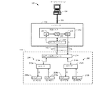
図1は、制御システム102、ワークステーション104、およびフィールド機器統合(FDI)サーバ106を含む、例示的プロセス制御環境100を示す、ブロック図である。例示的制御環境100は、制御システム102および/または他の制御システム(図示せず)と通信可能に連結されてもよい、追加のクライアント(図示せず)を含んでもよい。
FIG. 1 is a block diagram illustrating an exemplary
ワークステーション104(例えば、ターミナル、ワークステーション、PC)、例示的制御システム102、および/またはフィールド機器統合(FDI)サーバ106は、FDI標準を使用して通信する。FDIサーバ106は、HART、Foundation Fieldbus、および/またはProfibus等の異なる標準を使用して動作する、異なるネットワーク上のデバイスとインターフェースする。一般に、FDI標準は、デバイスの製造者および/またはサプライヤが、デバイスが本来準拠している標準に関係なく、顧客によって使用することができ、一様にデバイスを管理することができるツールセットを構築できるようにする仕様を提供する。FDI標準は、標準電子デバイス記述言語(EDDL)のテキストベースのファイル(例えば、XMLファイル)が、デバイス、デバイスによって提供される方法、デバイスによってサポートされる測定値およびデバイスパラメータ、デバイスのコンフィギュレーション情報、および/またはユーザがデバイスとともに有することができる相互動作を記述できる、テキストデバイス記述方法を含む。
The workstation 104 (eg, terminal, workstation, PC),
FDI標準は、アプリケーションおよび/またはデバイスが通信する方法をさらに提供する。通信方法は、通信チャネルを介してメッセージを送信および受信する、メッセージバスの通信方法と類似している。メッセージバスの方法は、アプリケーション、コントローラ、サーバ、および/またはデバイスが、受信しているアプリケーションまたはデバイスの内部動作に関する特定の詳細のすべてを知る必要なく、相互動作できるようにする。メッセージバスのアプローチに加えて、FDI標準は、アプリケーション、コントローラ、サーバ、および/またはデバイスからサービスを要求する、サービス指向の方法のための特徴を提供する。このサービス指向の方法の下、アプリケーション、コントローラ、サーバ、および/またはデバイスは、契約およびメッセージを使用して、機能性を露呈および消費する。サービス方法は、アプリケーション、コントローラ、サーバ、および/またはデバイスによって、システムリソースおよび/またはシステム挙動を交渉、割り当て、割り当て解除、制限、管理、および診断するように使用されてもよい。 The FDI standard further provides a way for applications and / or devices to communicate. The communication method is similar to the message bus communication method of sending and receiving messages via a communication channel. Message bus methods allow applications, controllers, servers, and / or devices to interoperate without having to know all of the specific details regarding the internal operation of the receiving application or device. In addition to the message bus approach, the FDI standard provides features for service-oriented methods of requesting services from applications, controllers, servers, and / or devices. Under this service-oriented method, applications, controllers, servers, and / or devices use contracts and messages to expose and consume functionality. The service method may be used by applications, controllers, servers, and / or devices to negotiate, allocate, deallocate, limit, manage, and diagnose system resources and / or system behavior.
例示的ワークステーション104および例示的FDIサーバ106は、第1の通信バス108を介して通信している。FDIサーバ106は、通信バス108を、通信バス108と同一の種類であってもまたは異なる種類であってもよい、他の通信バス110および112と接続するか、または通信可能に連結する。FDIサーバ106は、通信バス108を介して、制御システム102とも通信している。したがって、ワークステーション104は、FDIサーバ106および通信バス108を介して、制御システム102内のデバイスのうちのいずれかと通信する。一部の例において、通信バス108〜112は、Foundation Fieldbusプロトコル、Profibusプロトコル、および/またはHARTプロトコルを使用して実装されてもよい。
The
HARTプロトコルは、ブロックデータ転送を行う方法を含み、これはバルブ診断および/または頻度分析等のより複雑なプロセス制御機能を行うように使用されてもよい。HARTブロックデータ転送方法は、そこを通ってデータストリームが、スレーブデバイスへ、またはスレーブデバイスから転送されてもよい、スレーブデバイスの特定ポートへの接続をホストが確立できるようにする。データの種類またはデータの機能は、スレーブデバイスにおいてどのポートを開くかを判定する場合がある。 The HART protocol includes a method for performing block data transfer, which may be used to perform more complex process control functions such as valve diagnostics and / or frequency analysis. The HART block data transfer method allows the host to establish a connection to a particular port of the slave device through which the data stream may be transferred to or from the slave device. The data type or data function may determine which port to open in the slave device.
同様に、Foundation Fieldbusは、最大16パラメータのサンプル(例えば、1パラメータで16サンプル、それぞれ2パラメータで8サンプル等)をプロセス制御デバイス上に保存するデータ構造である、トレンドオブジェクトを特定する。トレンドオブジェクトが充填されると、プロセス制御デバイスは、保存されたサンプルを含むトレンドオブジェクトを、例えば、プロセス制御ループにおいて使用されるインターフェースデバイス(例えば、コントローラ、プロセス制御アプリケーション等)に送信してもよい。特に、インターフェースデバイスは、サンプルを収集するプロセス制御デバイスとの単一相互動作を介して、プロセス制御変数の複数のサンプルにアクセスしてもよい。プロセス制御デバイスを構成することによって、プロセス制御デバイスは、新しいデータ群が収集される度に、トレンドオブジェクトの一部またはすべてをインターフェースデバイスに自動的に報告する場合がある。追加的にまたは代替的に、トレンドオブジェクトは、読み取りサービスを実装することによって、インターフェースデバイスにより任意の時点で読み取られる場合がある。 Similarly, Foundation Fieldbus identifies a trend object, which is a data structure that stores up to 16 parameter samples (eg, 16 samples with 1 parameter, 8 samples with 2 parameters each) on the process control device. Once the trend object is filled, the process control device may send the trend object containing the stored sample to an interface device (eg, controller, process control application, etc.) used in the process control loop, for example. . In particular, the interface device may access multiple samples of process control variables via a single interaction with the process control device that collects the samples. By configuring the process control device, the process control device may automatically report some or all of the trend objects to the interface device each time a new set of data is collected. Additionally or alternatively, the trend object may be read at any point by the interface device by implementing a read service.
例示的制御システム102は、製造施設、プロセス施設、オートメーション施設、および/または任意の他の種類のプロセス制御構造またはシステムのうちのいずれかの種類を含んでもよい。一部の例において、制御システム102は、異なる位置において複数の施設を含んでもよい。さらに、例示的制御システム102は、プロセス制御サブシステム114と関連付けられるが、制御システム102は、追加のプロセス制御システムを含んでもよい。
例示的プロセス制御サブシステム114は、データバス118を介して、コントローラ116と通信可能に連結される。プロセス制御サブシステム114は、任意の数のフィールド機器を含んでもよい(例えば、入力および/または出力デバイス)。フィールド機器は、入力を受信し、出力を生成し、および/またはプロセスを制御することができる、任意の種類のプロセス制御コンポーネントを含んでもよい。例えば、フィールド機器は、プロセスを制御するために、例えば、バルブ、ポンプ、ファン、ヒーター、クーラー、および/またはミキサー等の入力デバイスを含んでもよい。さらに、フィールド機器は、プロセスの部分を測定するために、例えば、温度計、圧力ゲージ、濃度ゲージ、液面計、流量計、および/または蒸気センサ等の出力デバイスを含んでもよい。入力デバイスは、コントローラ116からの命令を受信して、特定されたコマンドを実行し、かつプロセスに変更をもたらす場合がある。さらに、出力デバイスは、プロセスデータ、環境データ、および/または入力デバイスデータを測定し、かつ測定データをプロセス制御情報(例えば、プロセスデータ)として、コントローラ118に送信する場合がある。このプロセスデータは、各フィールド機器からの測定出力に対応する変数の値(例えば、測定プロセス変数および/または測定品質変数)を含んでもよい。
The exemplary
図1に例証されている実施例において、コントローラ116は、データバス118を介して、プロセス制御サブシステム114内のフィールド機器と通信してもよい。データバス118は、プロセス制御サブシステム114内の通信コンポーネントに連結されてもよい。通信コンポーネントは、I/Oカードを含み、データをフィールド機器から受信し、例示的コントローラ116が受信できる通信媒体にデータを変換する場合がある。さらに、これらのI/Oカードは、コントローラ116からのデータを、対応するフィールド機器により処理できるデータ形式に変換する場合がある。実施例において、データバス118は、Fieldbusプロトコルまたは他の種類の有線および/または無線通信プロトコル(例えば、Profibusプロトコル、HARTプロトコル等)を使用して、実装されてもよい。
In the embodiment illustrated in FIG. 1, the
コントローラ116は、任意の有線および/または無線接続を介して、FDIサーバ106と通信可能に連結される。コントローラ116は、コントローラ116がプロセス制御サブシステム114からプロセスデータを受信すると、プロセスデータをFDIサーバ106に送信する場合がある。他の実施例において、コントローラ106は、プロセスデータを一定の時間間隔で(例えば、毎分、毎時、毎日等)FDIサーバ106に送信してもよい。あるいは、FDIサーバ106は、コントローラ116からのプロセスデータを要求してもよい。
The
プロセスデータを受信する際に、図1の例示的FDIサーバ106は、プロセスデータをファイルシステム(図示せず)内に保存する。ファイルシステムは、プロセス制御サブシステム114内のデバイスに基づいて、および/またはプロセス制御サブシステム114を管理するようにコントローラ116内で動作するルーチン(例えば、アプリケーションおよび/またはアルゴリズム)に基づいて、ディレクトリおよび/またはサブディレクトリとともに、階層様式で配列される場合がある。他の実施例において、ファイルシステムは、制御システム102のオペレータによって配列されてもよい。プロセスデータは、関連付けられたディレクトリおよび/またはサブディレクトリ内のパラメータに対して保存されてもよい。一部の例において、パラメータは、コントローラ116上で動作するルーチンと関連付けられるか、またはプロセス制御環境100内のフィールド機器出力と関連付けられた変数であってもよい。パラメータは、パラメータと関連付けられたプロセスデータの種類を記述する、メタデータを含んでもよい。
Upon receiving process data, the
例示的ワークステーション104は、プロセス制御システムと関連付けられたプロセスデータを読み取る、書き込む、および/またはサブスクライブすることが承認される場合がある個人と関連付けられてもよい。ワークステーション104は、遠隔位置からプロセス制御環境100にアクセスする場合がある制御システム102と関連付けられた人員と関連付けられてもよい。ワークステーション104は、任意の有線および/または無線通信媒体(例えば、インターネット)を使用して、FDIサーバ106を介して、プロセス制御環境100にアクセスしてもよい。
The
例示的FDIサーバ106は、ワークステーション104上で操作するクライアントアプリケーション120のユーザがプロセスデータを見ることができるように、プロセスデータをフォーマットすることができる。図1の実施例は、インターフェース122においてプロセスデータを表示する、クライアントアプリケーション120を示す。例えば、クライアントアプリケーション120は、ウェブクライアントディスプレイアプリケーションを含んでもよい。FDIサーバ106は、ウェブページを作成する、および/またはテンプレートウェブページにアクセスする、およびデータフィールドをウェブページ内に配置するか、または組み込むことによって、ウェブサーバアプリケーションに対するプロセスデータをフォーマットする場合がある。次に、インターフェース122は、ウェブブラウザを介して、html要求および応答を使用して、FDIサーバ106においてホストされるウェブページにアクセスすることによって、プロセスデータを表示する場合がある。あるいは、FDIサーバ106は、クライアントアプリケーション120において、ウェブブラウザ(例えば、インターフェース122)内で実行可能である場合があるか、またはワークステーション104(例えば、Windows(登録商標)オペレーティングシステムアプリケーション、アプリケーションプラグイン)に対してネイティブである場合がある、ウェブアプリケーション(例えば、ActiveX、Adobe Flash(商標)および/またはSilverlight(商標))を初期化することによって、クライアントディスプレイアプリケーションに対するプロセスデータをフォーマットする場合がある。
The
ワークステーション104、FDIサーバ106、および/またはコントローラ116は、通信バス108−112を介して、他のデバイス128、130、132、134、136と通信する場合がある。例示的デバイス128〜136は、ワークステーション、ターミナル、コントローラ、通信ネットワークドロップノード、通信デバイス(例えば、モデム、ネットワークゲートウェイ)および/または任意の他の種類の入力、出力、および/または制御デバイスを含んでもよい。一部の例において、ワークステーション104、FDIサーバ106、および/またはコントローラ116は、同期転送、ブロックデータ転送、および/またはデータバス108〜112を介して通信する他の方法を使用して、デバイス128〜136に対して、および/またはデバイスから情報を転送してもよい(例えば、データ処理、データログ、および/または他の目的で)。
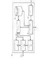
図2は、例示的プロセス制御サブシステム114、および制御ループ202を動作させる、図1の例示的コントローラ116を示す。図2は、2組のフィードバックループ204および206をさらに含む。第1のフィードバックループ204は、I/Oカード212aに連結される、フィールド機器208a(例えば、バルブ)および210a(例えば、圧力センサ)を含む。第2のフィードバックループ206は、I/Oカード212bに連結される、フィールド機器208b(例えば、バルブ)および210b(例えば、別の圧力センサ)を含む。
FIG. 2 illustrates the example
図2に示されるように、プロセス制御環境100は、図1のワークステーション104を含み、これは1つまたは複数の通信ネットワーク(例えば、通信バス108)を介して、コントローラ116と通信可能に連結される。コントローラ116は、プロセス制御サブシステム114内で(例えば、図1のデータバス118を介して)I/Oデータ取得モジュール214とも通信可能に連結される。I/Oデータ取得モジュール214は、それぞれの通信経路216aおよび216b(例えば、2地点間接続)は、それぞれの通信経路216aおよび216b(例えば、2地点間接続)を介して、I/Oカード212aおよび212bと通信可能に連結される。
As shown in FIG. 2, the
図2の例示的コントローラ116は、I/Oスケジューラ218を含む。一部の例において、コントローラ116は、I/Oデータ取得モジュール214も含んでもよく、この場合、コントローラ116は、通信バス108を介して、および/または通信経路216aおよび216bを介して、例示的I/Oカード212aおよび212bと通信する場合がある。他の実施例において、I/Oデータ取得モジュール214は、I/Oカード212aおよび212b内で実装されてもよい。
The
制御ループ202は、入力信号プロセッサまたは機能ブロック(AI)220、比例−積分−微分制御動作計算器または機能ブロック(PID)222、および出力信号生成器または機能ブロック(AO)224を含む。AI220、PID222、および/またはAO224は、I/Oデータ取得モジュール214によって生成されたデータを使用して、プロセスを制御する場合がある。通信バス118を介してデータを送信するために、例示的I/Oデータ取得モジュール214は、センサ210aおよび210bからの信号を受信し、および信号をサンプリングして、信号を代表するデータを生成する。I/Oデータ取得モジュール214は、次に、データをコントローラ116に送信する。
The
センサ210aおよび210bからの信号の収集および/またはサンプリングレートは、センサ210aおよび210bによって生成された信号を記述する、それぞれのEDDファイル(EDDLで書き込まれた)に基づく場合がある。例えば、I/Oデータ取得モジュール214が、関連付けられたEDDファイルに基づいて、センサ210aが温度測定値を提供することを決定した場合、I/Oデータ取得モジュール214は、比較的低速で、センサ210aから受信された信号をサンプリングする場合がある。対照的に、I/Oデータ取得モジュール214が、関連付けられたEDDファイルに基づいて、センサ210bが圧力測定値を提供することを決定した場合、I/Oデータ取得モジュール214は、比較的高速で、センサ210bから受信された信号をサンプリングする場合がある。EDDファイルおよび/またはサンプリングレートに基づいて、I/Oデータ取得モジュール214は、次に、異なるレートで、および/または異なる送信方法を使用して、サンプルデータをコントローラ116に送信してもよい。
The collection and / or sampling rate of signals from
制御ループ202内の制御アルゴリズムおよび/またはルーチンは、AI220から入力データを受信し、PID222を使用して入力データを処理し、AO224を介して出力データを生成する。単一の制御ループサイクルは、複数のルーチンおよび/または制御アルゴリズムを含んでもよい。他の実施例において、制御ループ202は、他の種類のAI、PID、および/またはAOを含んでもよい。さらに、他の実施例は、複数のAI220、PID222、および/またはAO224を含んでもよい。
A control algorithm and / or routine in
一部の例において、センサ210a〜210b、I/Oカード212a〜212b、I/Oデータ取得モジュール214、および/またはコントローラ116(I/Oスケジューラ218、AI220、PID222、および/またはAO224を含む)のうちのいずれかは、デジタル通信する場合がある。例えば、デジタル通信は、プロセス制御データ、例えば、アナログデータのデジタルサンプルを、デジタル通信バスを通して送信する場合がある。これらの実施例において、センサ210a〜210b、I/Oカード212a〜212b、I/Oデータ取得モジュール214、および/またはコントローラ116は、例えば、プロセス制御変数、プロセス制御変数のサンプリング頻度、および/またはプロセス制御変数にアクセスする標準および/または特別な方法の定義を記述する、電子デバイス記述ファイルに基づいて、デジタルサンプルを保存、送信、および/または受信する場合がある。センサ210a〜210b、I/Oカード212a〜212b、I/Oデータ取得モジュール214、および/またはコントローラ116のうちのいずれかを実装するために使用される場合がある、例示的プロセス制御デバイスおよび例示的プロセス制御アプリケーションおよび/またはコントローラは、図3および4と併せて以下に記述される。さらに、処理用のデータ転送に使用される場合がある例示的プロセスは、図6および7に記載される。
In some examples,
プロセス制御サブシステム114および制御ループ202aの運用実施例において、センサ210aは、パイプ内の流体の圧力値を含む入力信号を、I/Oカード212aおよび/またはI/Oデータ取得モジュール214に送信する。一部の例において、センサ210aは、I/Oデータ取得モジュール214からの要求時に、入力信号を送信する場合がある。I/Oデータ取得モジュール214は、入力信号を転送し、かつ/または入力信号を代表するデータは、制御ループ202を介して転送および処理される。制御ループ202は、次に、入力データを使用して、バルブ208aの制御動作を計算する。コントローラ116は、I/Oカード212aを介して出力信号に変換される場合がある、出力データを介して、この制御動作をバルブ208aに送信する。バルブ208aは、出力データおよび/または出力信号を受信し、出力データおよび/または信号の値に基づいて、その位置を変更する。データ処理の実施例において、圧力信号は、センサ210aによって生成され、圧力データを生成するようにI/Oカード212aおよび/またはI/Oデータ取得モジュール214においてサンプリングされ、EDDファイルに従って、頻度分析のために、I/Oカード212aおよび/またはI/Oデータ取得モジュール214からコントローラ116に転送される場合がある。
In the operational embodiment of
I/Oスケジューラ218および/またはコントローラ116は、センサ210aおよび210bを起源とする入力信号のタイミングを管理する。I/Oスケジューラ218は、制御ループ202の各予定期間中に、入力信号を制御ループ202に転送する。例えば、制御ループ202は、コントローラ116がセンサ210aを起源とする入力信号を受信する予定期間、およびコントローラ116がセンサ210bを起源とする入力信号を受信する予定期間を含む。これらの予定期間は、制御ループ202が入力信号のそれぞれを利用および/または処理する前に、制御ループ202が、それぞれのセンサ210aおよび210bから入力信号のそれぞれを受信するように、事前設定されてもよい。一部の例において、コントローラ116は(例えば、I/Oスケジューラ218を介して)、センサ210aおよび210bによって生成されたデータをサブスクライブする。コントローラ116は、センサ210aおよび210bのEDDファイルからデータの種類を判定する場合がある。
I /
AI220は、I/Oスケジューラ218から入力データを受信し、PID222内で処理するための入力データを構成する。I/Oスケジューラ218は、各入力信号の予定期間中に、入力データをAI220に転送する場合があり、かつ/または入力データを収集し、データ構造を使用して、入力データをバルクで転送する場合がある。実施例において、制御ループ202によって処理するために入力データが必要とされる予定期間の開始前に、入力データがI/Oスケジューラ218によって受信される場合、I/Oスケジューラ218は、予定期間まで入力データの転送を遅延させる。他の例において、I/Oスケジューラ218が、予定期間の終了までに入力データを受信しなかった場合、AI220は、同一のフィールド機器から以前に送信された入力データを利用してもよい。I/Oスケジューラ218および/またはコントローラ116は、同一のフィールド機器からの後続の入力データのタイミングを調整して、I/Oスケジューラ218が、予定期間中に入力データを受信するようにしてもよい(すなわち、例えば、制御ループ202を実行する場合に、データがコントローラ116による処理に必要とされる時間に先行する期間)。他の実施例において、I/Oスケジューラ218および/またはコントローラ116は、同一フィールド機器からの後続の入力データのタイミングを増分的に調整して、受信された入力データのタイミングにおけるオーバーシュートを回避する場合がある。
The
別の運用実施例において、センサ210aは、5ミリ秒(ms)毎に、圧力入力信号を送信する。一部の例において、I/Oデータ取得モジュール214は、入力値に対して、5ms反復サイクルで、センサ210aをポーリングまたは照会する場合がある。その場合、センサ210aは、第1の圧力データを生成し、第1の圧力信号をI/Oデータ取得モジュール214に送信する。5ミリ秒後、センサ210aは、第2の圧力信号を生成し、第2の圧力信号から5ms後に、センサ210aは、第3の圧力信号を生成する、等々となる。I/Oデータ取得モジュール214は、I/Oカード212aを介して第1の圧力信号および/またはデータを受信し、データをI/Oスケジューラ218に転送する。一部の例において、I/Oデータ取得モジュール214は、I/Oデータ取得モジュール214が、センサ210aおよび210bから信号を受信および/またはサンプリングすると、データをコントローラ116(例えば、I/Oスケジューラ218)に送信する場合がある。一部の他の実施例において、I/Oデータ取得モジュール214は、データ構造(例えば、トレンドオブジェクト、配列オブジェクト)を投入し、バルクデータ転送を使用して、データ構造中のデータをコントローラ116に転送する場合がある。
In another operational embodiment,
圧力データを受信する際、制御ループ202は、バルブ208aに対する制御動作を計算する。例えば、圧力データは、1805バールの圧力値を示す場合がある。PID222は、次に、この値を定義された閾値1700バールと比較する場合がある。閾値を超える105バールの差異は、次に、バルブ208aを開いて、パイプ内の圧力をバール1700未満に低下させる制御動作をPID222に計算させる場合がある。この計算された制御動作は、AO224によって生成され、I/Oカード212aを介してバルブ208aに送信された出力データ内で提供され、制御データをアナログ信号に戻すように変化する場合がある。出力信号を受信する際に、バルブ208aが開いて、パイプ内の圧力を低下させる。
Upon receiving pressure data, the
図3は、プロセス制御データを生成、保存、および送信する、図1および図2のプロセス制御環境100内にある例示的プロセス制御デバイス300のブロック図である。例示的プロセス制御デバイス300を使用して、図1の例示的プロセス制御デバイス128〜136および/または図2のセンサ210aおよび210bのうちのいずれかを実装する場合がある。追加的にまたは代替的に、例示的プロセス制御デバイス300は、図2のコントローラ116および/またはI/Oカード212aおよび212bを実装する場合がある。
FIG. 3 is a block diagram of an exemplary
例示的プロセス制御デバイス300は、センサ302、アナログデジタル変換器(ADC)304、およびプロセッサ306を含む。プロセッサ306は、サンプルストレージ308を生成および/または維持し、以下でさらに詳述される。プロセス制御アプリケーションまたは他のプロセス制御デバイスと通信するために、例示的プロセス制御デバイス300は、ネットワークインターフェース310、ポートコントローラ312、およびレジストラ314を含む。
The exemplary
例示的センサ302は、プロセス制御変数、例えば、温度、圧力および/または他の変数を測定する。多くのプロセス制御測定値は、測定され、トランスデューサによって電子信号に変換されると、連続アナログ信号をもたらす連続状態である。アナログ信号は、図2と併せて上述されるように、制御ループの一部として取得、増幅、変更、フィルター、および/または送信される場合がある。
The
デジタル通信ネットワークに沿って、測定値が他のデバイスに送信される一部の他の実施例において、ADC304は、サンプリングを介して、アナログ信号をデジタル表示に変換する。一部の例において、測定されているプロセス制御変数は、比較的ゆっくり変化する(例えば、100ms以上毎)。これらの例において、ADC304は、比較的低速で、センサ302からの信号をサンプリングする。信号サンプリングの間が長いため、サンプルは、プロセス制御バス(例えば、HART、Fieldbus、Profibus)を介して、ADC304がサンプルを生成する時に、コントローラおよび/またはプロセス制御アプリケーションに送信される場合がある。サンプルを送信するために、ADC304は、サンプリングした値をプロセッサ306に提供し、ネットワークインターフェース310を介して、サンプリングされた値を送信する。一部の例において、プロセッサ306は、サンプリングされた値の信頼値(例えば、良い、悪い、または疑わしい等のステータス)を判定し、信頼値をサンプルの一部として送信する。追加的にまたは代替的に、プロセッサ306は、タイムスタンプをデータに追加して、データの処理を提供する場合がある。
In some other examples where measurements are sent to other devices along a digital communications network, the
他の実施例において、測定された変数は、より高いレートで変化する(例えば、高頻度のコンポーネントを含む)。高頻度のコンポーネントが関心対象である場合、ADC304は、より高いレートで変数をサンプリングする(例えば、関心対象の最高頻度コンポーネントの頻度の少なくとも2倍)。サンプルが生成されたとき、高頻度サンプリングの結果として、プロセス制御バスを介して送信されない場合があり、そのような転送は、通信バスの帯幅を圧倒する可能性があるためである。代わりに、プロセッサ306は、サンプリングされた値を有するサンプルストレージ308を形成および投入する。例示的サンプルストレージ308は、サンプリングされた値のそれぞれの信頼性をさらに保存する場合がある。使用されてもよい例示的サンプルストレージ308は、Foundation Fieldbus標準の一部として定義されるトレンドオブジェクトである。サンプルストレージ308が閾値サイズ(例えば、閾値サンプル数)に到達した場合、以下でさらに詳述されるように、プロセッサ306は、サンプルストレージ308のコンテンツのすべてまたは一部をコントローラおよび/またはプロセス制御アプリケーションに転送する。一部の例において、他の状態(例えば、″TAG/PV″>″someLimit″)および/またはイベント(例えば、″TAG/Highlimit″=″True″)は、サンプルストレージ308からのデータの転送をトリガする場合がある。
In other examples, the measured variable changes at a higher rate (eg, includes high frequency components). If a high frequency component is of interest, the
サンプルストレージ308は、例えば、アレイ、マトリクス、クラス、構造、および/またはサンプルデータを送信するために使用される、保存されるデータおよび/または通信プロトコルに対する任意の他の種類の適切なデータ構造を使用して、サンプルデータを組織化する場合がある。アレイを使用して、サンプルストレージ308は、浮動小数点数(例えば、floats)および/または整数(例えば、ints)等の単純な種類のデータタイプ、ならびにストラクトオブジェクト等のより複雑なデータタイプを保存する場合がある。ストラクトオブジェクトは、例えば、値、状態、品質情報、タイムスタンプ、および/またはデータサンプルに関する他の情報を保存する場合がある。マトリクスの使用は、アレイに類似する場合があるが、相関されるサンプルを保存するために有利に使用される場合があり、共通のデータ構造に同時に保存される必要がある。データサンプルをクラスまたはストラクトとして保存することは、データおよび/またはデータの特性を拡大、修正、および/または別の方法として、アレイおよびマトリクスでは不可能な方法で操作することができる。
ネットワークインターフェース310は、プロセス制御通信バス、例えば、HART、Foundation Fieldbus、および/またはProfibus手順と相互作用するために適切なインターフェース手順を含む。図3に例証される例示的通信バスは、図1の通信バス118である。ネットワークインターフェース310は、プロセッサ306と相互作用して、通信バス118に対して、および/または通信バス118からメッセージを送信し、かつ/またはポートコントローラ312を用いて、他のデバイスとの通信のために開いたポートを管理する。例えば、ポートコントローラ312は、指定されたポート上のブロックデータ転送を介して、サンプル構造308中のサンプルデータに対するネットワークインターフェース310を経由して、プロセス制御アプリケーション(例えば、図1のアプリケーション120)からの要求を受信する場合がある。要求が承認されることをポートコントローラ312が決定する場合、ポートコントローラ312は、ポートを開き、そこを通ってサンプルデータが要求しているアプリケーションに送信される、ポートのプロセッサ306に通知する。一方、要求が承認されないことをポートコントローラ312が決定する場合、ポートコントローラ312は、要求を破棄し、かつ/またはプロセッサ306に要求を破棄するように命令する。
The
レジストラ314は、例示的プロセス制御デバイス300をプロセス制御環境100に登録する。登録は、例えば、プロセス制御デバイス300が、プロセス制御環境100に初めて接続されると起こる場合がある。一部の例において、登録は、プロセス制御デバイス300が、プロセス制御環境100に接続および/または再接続されるたびに、および/またはプロセス制御デバイス300が構成変更(例えば、プロセス制御デバイス300物理的位置の変更)を有する場合に起こる場合がある。プロセス制御デバイス300を登録するために、例示的レジストラ314は、この実施例では、EDDLを使用して書き込まれるEDDファイルを提供する。
EDDファイルを使用して、異なる製造者からの異なるフィールド装置に含まれる、診断、リアルタイム、および資産管理情報にアクセスしてもよい。EDDLを使用して、最新の自動化センサおよびアクチュエータにおいて使用可能な情報が、例えば、分配されたプロセス制御システムまたは携帯コミュニケータによってアクセスされて、構成し、プロセス制御デバイスを較正し、問題を診断し、かつ/またはユーザインターフェースディスプレイ用のデータおよび/またはアラームを提供する場合がある、相互運用可能な環境を提供してもよい。 The EDD file may be used to access diagnostic, real-time, and asset management information contained in different field devices from different manufacturers. Using EDDL, information available in the latest automated sensors and actuators can be accessed, for example, by distributed process control systems or portable communicators to configure, calibrate process control devices, diagnose problems And / or an interoperable environment that may provide data and / or alarms for user interface displays.
EDDLは、フィールド機器の特徴を記述するために使用される場合がある、テキストベースの言語である。デバイス製造者は、EDDLを使用して、EDDファイルを形成し、ホストシステムおよび携帯コミュニケータに対して一貫した形態および構造を提供して、通信プロトコルまたはデバイス動作システムから独立したフィールド装置内の情報にアクセスし、表示してもよい。EDDファイルは、装置設計者またはデバイス設計者によって形成され、EDDL構文を使用して、デバイスおよびそのパラメータを記述する。パラメータは、例えば、プロセス変数、セットポイント、上限−下限、大気温度等を含む場合がある。デバイス設計者は、インターフェースコンポーネント、例えば、EDDLを使用して、メニュー、パラメータディスプレイ、ディスプレイ状態等をさらに定義してもよい。 EDDL is a text-based language that may be used to describe the characteristics of field devices. Device manufacturers use EDDL to form EDD files, providing a consistent form and structure for host systems and portable communicators, and information in field devices independent of communication protocols or device operating systems. May be accessed and displayed. The EDD file is formed by a device designer or device designer and describes the device and its parameters using EDDL syntax. The parameters may include, for example, process variables, set points, upper and lower limits, atmospheric temperature, and the like. The device designer may further define menus, parameter displays, display states, etc. using an interface component, eg, EDDL.
図4は、プロセス制御データを受信および/または操作する、図1および図2のプロセス制御環境100内の例示的プロセス制御アプリケーション400またはコントローラのブロック図である。明確および簡潔にするために、図4の例示的ブロック図は、図1のクライアント120等のクライアントデバイス上で実行されるプロセス制御アプリケーションを参照して説明される。しかしながら、図4の例示的プロセス制御アプリケーション400を使用して、プロセス制御サーバ、スタンドアロン型後処理アプリケーション、プロセスコントローラ、またはプロセス制御システムの状況において、制御および/または後処理機能を実行する場合がある、任意の他の種類のプロセス制御デバイスも実装される場合がある。
FIG. 4 is a block diagram of an exemplary
例示的プロセス制御アプリケーション400は、後処理装置402、ストレージ404、ユーザインターフェース406、EDDファイルリーダー408、ネットワークインターフェース410、およびポートコントローラ412を含む。例示的後処理装置402は、プロセス制御データ(例えば、温度、圧力等のトレンドデータ)を受信し、1つまたは複数の後処理動作をデータ上で行う。例えば、後処理は、頻度分析、診断、データロギング、ゲージシステム、および/または任意の他の後処理および/または制御アプリケーションを含んでもよい。
The exemplary
一部の後処理アプリケーション(例えば、後処理装置402)は、比較的大量のデータを必要とする場合がある。プロセス制御通信バス(例えば、通信バス108)を介して、プロセス制御データを取得するために、後処理装置402は、プロセス制御データ(例えば、センサ、コントローラ)のソースからデータを要求する場合があり、かつ/またはデータのソースが通信バス108を介してデータを受信すると、データを受信する場合がある。
Some post-processing applications (eg, post-processing device 402) may require a relatively large amount of data. In order to obtain process control data via a process control communication bus (eg, communication bus 108), the
ストレージ404は、後処理に先立ってプロセス制御データを保存し、および/または後処理装置402によって生成される結果を保存する。例えば、プロセス制御アプリケーション400が、ソースからプロセス制御データを受信すると、プロセス制御データは、後処理装置402が所望の後処理動作を実行するために十分なデータが収集されるまで、ストレージ404に保存される。追加的にまたは代替的に、後処理装置402が後処理動作を実行し、結果(例えば、頻度スペクトル、データログ等)を生成した後、結果は、ストレージ404に保存される場合がある。ストレージ404から、結果は、別のプロセス制御デバイスおよび/またはアプリケーションに送信され、要求に応じてプロセス制御環境100のユーザによって視認され、かつ/または他のデータと併せてさらに処理される場合がある。
後処理装置402は、ユーザインターフェース406と相互作用して、後処理動作の結果をユーザに提示し、および/または後処理データの要求を受信する。例えば、ユーザが特定のバルブにおける圧力の頻度分析を視認したい場合、ユーザは、バルブを選択し、例示的プロセス制御アプリケーション400に、ユーザインターフェース406を介して(例えば、コンピュータキーボードおよび/またはコンピュータマウスを介して)頻度分析を行うように命令してもよい。選択したバルブに関連付けられた圧力センサからデータを抽出することを含む、頻度分析を行った後、後処理装置400は、ユーザインターフェース406を介して(例えば、ディスプレイモニタを介して)、頻度分析をユーザに表示する。
The
例示的ネットワークインターフェース410は、図3のネットワークインターフェース310に類似するか、または同一であってもよい。しかしながら、ネットワークインターフェース410は、スレーブインターフェースとは対照的に、通信バスの種類に応じて(例えば、Fieldbus)、ホストインターフェースであってもよい。データをプロセス制御デバイスから抽出するために、後処理装置402は、ネットワークインターフェース410を介して、選択したデバイス(例えば、ユーザにより選択されたバルブのコントローラ)のEDDファイルにアクセスする。EDDリーダー408は、EDDファイルを読み取り、選択したデバイスからプロセス制御データにアクセスする方法を判定する。例えば、EDDファイルは、プロセス制御デバイスによって使用される際のプロセス制御変数の定義、プロセス制御変数のサンプリング頻度、プロセス制御変数にアクセスする標準および/または特別な方法等を含んでもよい。
The
EDDファイルに基づいて、後処理装置402は、ポートコントローラ412に命令し、プロセス制御アプリケーション400上の対応するポートを使用して、スレーブデバイス(例えば、図3のプロセス制御デバイス300)上の特定のポートへの接続を確立させる。ポートコントローラ412は、プロセス制御デバイス300上のポートと通信するためにプロセス制御アプリケーション上で使用されるポートを判定し、ネットワークインターフェース410を介して、コマンドをプロセス制御デバイス300に送信する。プロセス制御デバイス300がコマンドに応答すると、通信バス108上の指定ポート間にパイプラインが形成される。ポート間にパイプラインが形成されたという確認を受信した後、後処理装置402は、プロセス制御デバイス300において収集された所望のデータを要求し、パイプラインを介してデータを受信する。
Based on the EDD file, the
プロセス制御デバイス300とプロセス制御アプリケーション400との間のデータ転送は、例えば、トレンドオブジェクト(例えば、Fieldbusを使用して)および/またはデータストリーミングを使用して、ブロックデータ転送を介して達成される場合がある。一部のプロセス制御通信プロトコル(例えば、HART、Fieldbus)において、同期通信のために事前定義されたバス時間または最小量のバス時間が確保され、これは一般に、待ち時間に敏感なアプリケーションによって使用される。バス時間の残りは、他の非同期通信、例えば、ブロックデータ転送に使用されてもよい。ブロックデータ転送は、プロセス制御デバイス300からプロセス制御アプリケーション400へのデータの複数サンプルの転送をもたらす。データサンプルは、追加として、それらのサンプルの信頼性の指標を含んでもよい(例えば、良い、疑わしい、悪いステータス)。
Data transfer between the
一部の例において、プロセス制御アプリケーション400は、アレイまたはマトリクスパラメータ、および/またはクラスあるいはストラクト特性を参照することによって、プロセス制御デバイス300中のプロセス制御データにアクセスする場合がある。例えば、デバイスアレイパラメータにアクセスするために、プロセス制御アプリケーションは、図5に示される命令500を実行する場合がある。図5の例示的な命令500は、プロセス制御アプリケーション(例えば、図4のプロセス制御アプリケーション400)によって、プロセス制御デバイス(例えば、図3のデバイス300)上に保存されるプロセス制御データにアクセスするために使用される場合がある方法を示す。プロセス制御アプリケーション400は、プロセス制御デバイス300上の所望のデータが、″args″という名前のFrequencyCaptureオブジェクト(例えば、アレイ)として保存されることを決定する(例えば、EDDリーダー408を介して)。したがって、プロセス制御アプリケーション400が命令500を実行すると、プロセス制御アプリケーション400は、ブロックデータ転送を介して、args中のプロセス制御データを取得する。一部の例において、プロセス制御データは、例示的命令500を開始する前(例えば、方法のコール前に)転送される。
In some examples, the
図1および図2の例示的コントローラ116、例示的クライアントアプリケーション120、例示的プロセス制御デバイス128−136、および/または例示的I/Oカード212a〜212bを実装する例示的方法は、図3および図4に示されたが、図3および図4に示される要素、プロセス、および/またはデバイスのうちの1つまたは複数を、任意の他の方法で、複合、分割、再配置、省略、排除、および/または実装してもよい。さらに、図3および図4の例示的センサ302、例示的ADC304、例示的プロセッサ306、例示的サンプルストレージ308、例示的ネットワークインターフェース310、例示的ポートコントローラ312、例示的レジストラ314、例示的後処理装置402、例示的ストレージ404、例示的ユーザインターフェース406、例示的EDDリーダー408、例示的ネットワークインターフェース410、例示的ポートコントローラ412、および/または、より一般的には、例示的プロセス制御デバイス300および/または例示的プロセス制御アプリケーション400は、ハードウェア、ソフトウェア、ファームウェア、および/またはハードウェア、ソフトウェア、および/またはファームウェアの任意の組み合わせによって実装されてもよい。したがって、例えば、例示的センサ302、例示的ADC304、例示的プロセッサ306、例示的サンプルストレージ308、例示的ネットワークインターフェース310、例示的ポートコントローラ312、例示的レジストラ314、例示的後処理装置402、例示的ストレージ404、例示的ユーザインターフェース406、例示的EDDリーダー408、例示的ネットワークインターフェース410、例示的ポートコントローラ412、および/または、より一般的には、例示的プロセス制御デバイス300および/または例示的プロセス制御アプリケーション400のうちのいずれかは、1つまたは複数の回路、プログラム可能プロセッサ、特定用途向け集積回路(ASIC)、プログラム可能論理デバイス(PLD)、および/またはフィールドプログラム可能論理デバイスは(FPLD)等によって実装できる可能性がある。添付の装置クレームのうちのいずれかが、純粋にソフトウェアおよび/またはファームウェア実装を網羅すると読み取られる場合、例示的センサ302、例示的ADC304、例示的プロセッサ306、例示的サンプルストレージ308、例示的ネットワークインターフェース310、例示的ポートコントローラ312、例示的レジストラ314、例示的後処理装置402、例示的ストレージ404、例示的ユーザインターフェース406、例示的EDDリーダー408、例示的ネットワークインターフェース410、および/または例示的ポートコントローラ412のうちの少なくとも1つは、メモリ、DVD、CD等のコンピュータ可読媒体を含み、ソフトウェアおよび/またはファームウェアを保存するように、本明細書において明示的に定義される。さらに、図3および図4の例示的プロセス制御デバイス300および/または例示的プロセス制御アプリケーション400は、図3および図4に図示されたもの、に加えて、またはその代わりに、1つまたは複数の要素、プロセス、および/またはデバイスを含む場合があり、かつ/または例証される要素、プロセス、およびデバイスのうちのいずれか2つ以上、またはすべてを含んでもよい。
An exemplary method for implementing the
図1および図2の例示的コントローラ116、例示的クライアントアプリケーション120、例示的プロセス制御デバイス128〜136、および/または例示的I/Oカード212a〜212bを実装するための例示的プロセスまたは方法を代表するフローチャートは、図6および図7に示される。この実施例において、方法は、図8に関連して以下で論じられる、例示的コンピュータ800において示されるプロセッサ802等のプロセッサによる実行のためのプログラムを使用して実装されてもよい。プログラムは、コンピュータ可読媒体、例えば、CD−ROM、フロッピー(登録商標)ディスク、ハードドライブ、デジタル多用途ディスク(DVD)、またはプロセッサ802と関連付けられるメモリ上に保存されるソフトウェアにおいて具体化される場合があるが、プログラム全体および/またはその部分は、代替として、プロセッサ802以外のデバイスによって実行できる可能性があり、かつ/またはファームウェアまたは専用ハードウェアにおいて具体化される。さらに、例示的プログラムは、図6および図7において例証されるフローチャートを参照して説明されるが、図1および図2の例示的コントローラ116、例示的クライアントアプリケーション120、例示的プロセス制御デバイス128〜136、および/または例示的I/Oカード212a〜212bを実装する多くの他の方法が、代替として使用されてもよい。例えば、ブロックの実行順序は変更されてもよく、および/または説明されるブロックの一部は、変更、排除、または組み合わされてもよい。
Representative of an exemplary process or method for implementing the
上述されるように、図6および図7の例示的方法またはプロセスは、有形のコンピュータ可読媒体、例えば、ハードディスクドライブ、フラッシュメモリ、読み取り専用メモリ(ROM)、コンパクトディスク(CD)、デジタル多用途ディスク(DVD)、キャッシュ、ランダムアクセスメモリ(RAM)および/または任意の他の記憶媒体上に保存される、符号化された命令(例えば、コンピュータ可読命令)を使用して実装されてもよく、情報は、そこに任意の期間保存される(例えば、延長された期間、永久的、短いインスタンス、一時的にバッファリングする間、および/または情報をキャッシングする間)。本明細書で使用される場合、用語「有形のコンピュータ可読媒体」は、任意の種類のコンピュータ可読ストレージを含み、信号の伝播を排除すること明示的に定義する。追加的にまたは代替的に、図6および図7の例示的プロセスは、持続性コンピュータ可読媒体、例えば、ハードディスクドライブ、フラッシュメモリ、読み取り専用メモリ、コンパクトディスク、デジタル多用途ディスク、キャッシュ、ランダムアクセスメモリ、および/または任意の他の記憶媒体上に保存される、符号化された命令(例えば、コンピュータ可読命令)を使用して実装されてもよく、情報は、そこに任意の期間保存される(例えば、延長された期間、永久的、短いインスタンス、一時的にバッファリングする間、および/または情報をキャッシングする間)。本明細書で使用される場合、用語「持続性コンピュータ可読媒体」は、任意の種類のコンピュータ可読ストレージを含み、信号の伝播を排除すること明示的に定義する。 As described above, the exemplary method or process of FIGS. 6 and 7 can be performed on a tangible computer readable medium such as a hard disk drive, flash memory, read only memory (ROM), compact disk (CD), digital versatile disk. (DVD), cache, random access memory (RAM), and / or implemented using encoded instructions (eg, computer readable instructions) stored on any other storage medium, information Is stored there for any period of time (eg, extended duration, permanent, short instance, temporarily buffered, and / or while caching information). As used herein, the term “tangible computer readable medium” explicitly includes any type of computer readable storage and excludes signal propagation. Additionally or alternatively, the exemplary processes of FIGS. 6 and 7 may be performed on a persistent computer readable medium such as a hard disk drive, flash memory, read only memory, compact disk, digital versatile disk, cache, random access memory. And / or may be implemented using encoded instructions (eg, computer readable instructions) stored on any other storage medium, where the information is stored for any period of time ( For example, extended duration, permanent, short instance, temporarily buffering, and / or while caching information). As used herein, the term “persistent computer readable medium” explicitly includes any type of computer readable storage and excludes signal propagation.
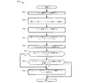
図6は、プロセス制御データサンプルを収集するように行われる場合がある、例示的方法600を代表するフローチャートである。例示的方法600を使用して、図1のプロセス制御デバイス128〜136、図2のセンサ210a〜210bおよび/または図3のI/Oカード212a〜212b、および/または図3の例示的プロセス制御デバイス300を実装してもよい。明確および簡潔にするために、例示的方法600は、図3の例示的プロセス制御デバイス300に関連して以下で論じられる。
FIG. 6 is a flowchart representative of an
例示的方法600は、プロセス制御デバイス300(ブロック602)を初期化する例示的プロセッサ306で開始する。初期化は、例えば、プロセス制御デバイス300が、図1のプロセス制御環境100に接続され、電源が入ると起こる場合がある。初期化後、または初期化の一部として、レジストラ314は、EDDファイルをプロセス制御サーバ(例えば、図1のFDIサーバ106)に登録する(ブロック604)。EDDファイルは、例えば、プロセス制御デバイス300によって提供されるサービス、プロセス制御デバイス300によって測定されるパラメータ、パラメータのサンプリングレート、および/またはプロセス制御デバイス300の他の記述を含んでもよい。
The
センサ302は、次に、1つまたは複数のプロセス制御パラメータ(例えば、温度、圧力等)を測定してもよい(ブロック606)。一部の例において、センサ302は、実質的に連続するパラメータの値を測定し、アナログ信号を出力する。ADC304は、プロセス制御パラメータに対応するサンプリングレートにおいて(例えば、パラメータの種類に基づいて)、測定されたプロセス制御パラメータをサンプリングし(例えば、センサ302からのアナログ信号をサンプリングする)、これによりデータサンプルを生成する(ブロック608)。ADC304および/またはプロセッサ306は、サンプルをデータストレージに保存する(ブロック610)。例えば、ADC304は、サンプルをサンプルストレージ308に提供してもよく、これは、サンプルを対応するデータ構造に保存する。使用される場合がある一部の例示的データ構造は、アレイオブジェクト、マトリクスオブジェクト、クラス、ストラクト、および/または他の種類のデータ構造を含む。
The
プロセッサ306は、1つまたは複数の特定イベントおよび/または状態(例えば、EDDにおいて定義されるような)が発生して、サンプルストレージ308からのデータの転送をトリガするか否かを判定する(ブロック612)。例えば、プロセッサ306は、サンプルストレージ308におけるサンプルの数が、閾値を越えるか否か(例えば、“TAG/PV”>“someLimit”であるという条件)を判定する場合があり、かつ/または指定されたアラームがフラグされたか否か(例えば、“TAG/Highlimit”=“True”、イベント)を判定する場合がある。一部の例において、閾値は、データサンプル、タイムスタンプ、および/またはステータスに関して、データ構造がその容量に到達するときを表す場合がある。他の実施例において、閾値は、ブロックデータ転送を介して、またはストリーミングデータによって、データサンプルを別のプロセス制御デバイスおよび/またはアプリケーションに効率的に転送するためのデータサイズの下限を表す場合がある。1つまたは複数の特定イベントおよび/または状態が発生しなかった場合(ブロック612)、プロセッサ306は、データストレージ中のサンプルの承認された要求が受信されたか否かを判定する(ブロック614)。プロセッサ306は、要求が、例えば、要求者の認証情報をアクセスリストと比較することによって承認されるか否かを判定してもよい。しかしながら、承認を判定する多くの方法は、サンプル要求が承認されるか否かを判定するために使用されてもよい。
The
要求が承認されない場合(ブロック614)、例示的方法600は終了する場合がある。代替的に、例示的方法600を反復して、サンプルの収集、サンプルの保存、データ要求の受信、および/またはデータストレージからのデータサンプルの送信を継続してもよい。一方、1つまたは複数の特定イベントおよび/または状態が発生した場合(ブロック612)、または承認されたサンプル要求が受信された場合(ブロック614)、例示的プロセッサ306は、データサンプルをプロセス制御アプリケーションに送信する(例えば、ネットワークインターフェース310を介して)(ブロック616)。例えば、ポートコントローラ312は、受信しているプロセス制御アプリケーション上の特定ポートに転送するためにポートを開く場合があり、かつ/またはプロセッサ306は、データ構造が閾値サイズに到達すると、ネットワークインターフェース310を介してデータをブロードキャストする。
If the request is not approved (block 614), the
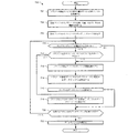
図7は、データサンプルを処理するように実行される場合がある、例示的方法700を表すフローチャートである。例示的方法700を使用して、図1の例示的FDIサーバ106および/または例示的コントローラ116、および/または図4の例示的プロセス制御アプリケーション400を実装してもよい。明確および簡潔にするために、例示的方法700は、図4の例示的プロセス制御アプリケーション400に関連して以下に説明される。
FIG. 7 is a flowchart representing an
例示的プロセス制御アプリケーション400は、パラメータ測定デバイス(例えば、プロセス制御デバイス300)に対応するEDDファイルを受信する(ブロック702)。EDDファイルに基づいて、EDDリーダー408は、名前、位置、および/またはEDDファイルと関連付けられるプロセス制御デバイス300によって測定されるパラメータの種類を判定する(ブロック704)。EDDリーダー408は、EDDファイルからパラメータのサンプリングレートをさらに判定する(ブロック706)。
The example
EDDリーダー408は、サンプリングレートが閾値よりも大きいか否かをさらに判定する(ブロック708)。例示的閾値は、ブロードキャストデータサンプルが生成されるときに、それらの伝播が実用的でなくなるサンプリングレートを表す場合がある。サンプリングレートが閾値よりも大きくない場合(ブロック708)、後処理装置402は、所望のパラメータを生成するプロセス制御デバイス300が、パラメータの加入契約をサポートする(例えば、定期的および/または非定期的間隔で、データを送信または受信する)か否かを判定する場合がある(ブロック710)。例示的プロセス制御デバイス300が、加入契約をサポートする場合(ブロック710)、以下でさらに詳述されるようにブロック718への転送を制御する。
The EDD reader 408 further determines whether the sampling rate is greater than a threshold (block 708). An example threshold may represent a sampling rate at which their propagation becomes impractical when broadcast data samples are generated. If the sampling rate is not greater than the threshold (block 708), the
EDDリーダー408が、サンプリングレートが閾値よりも大きいことを判定する場合(ブロック708)、またはプロセス制御デバイス300がサブスクライブをサポートしない場合(ブロック710)、ポートコントローラ412は、接続を確立することによって(例えば、ネットワークインターフェース410を介して)、プロセス制御デバイス300上のポートへのブロックデータ転送を開始する(例えば、ネットワークインターフェース310およびポートコントローラ312を介して)(ブロック712)。例えば、ポートコントローラ412は、ネットワークインターフェース410にオープンポートコマンドを送信させてもよく、これは次に、プロセス制御デバイス300によって承認または却下される。プロセス制御デバイス300とプロセス制御アプリケーション400とのポート間の接続は、プロセス制御デバイス300がオープンポートコマンドを承認すると確立される(例えば、プロセス制御アプリケーション400が、要求されたパラメータへのアクセスを承認される場合)。
If the EDD reader 408 determines that the sampling rate is greater than the threshold (block 708), or if the
接続を確立した後、後処理装置402は、プロセス制御デバイス300からのパラメータに対応するデータサンプルの転送を行う(ブロック714)。一部の例において、プロセス制御デバイスは、サンプル値、ステータス、および/またはタイムスタンプを含む、データサンプルを含有するトレンドオブジェクトを送信する。しかしながら、他の形態のブロックデータ転送もまた使用されてもよい。後処理装置402は、受信されたデータサンプルをストレージ404に保存する(ブロック716)。
After establishing the connection, the
サンプリングレートが、閾値よりも大きくなく(ブロック708)、プロセス制御デバイス300がサブスクライブをサポートする場合(ブロック710)、後処理装置402は、プロセス制御デバイス300からのブロードキャストデータサンプルを受信し、データサンプルをストレージ404に保存する(ブロック718)。要求されたデータサンプル(ブロック714)および/またはブロードキャストデータサンプル(ブロック718)を受信および/または保存した後、例示的後処理プロセッサ402は、十分なデータサンプルがデータサンプルを処理するために受信および/または保存されたか否かを判定する(ブロック720)。後処理プロセッサ402および/またはストレージ404が、十分なデータサンプルを有しない場合(ブロック720)、制御は、ブロック708に戻り、データサンプルの収集を継続する。
If the sampling rate is not greater than the threshold (block 708) and the
十分なデータサンプルがある場合(ブロック720)、後処理装置402は、所望の分析または後処理操作に従って、データサンプルを処理する(ブロック722)。例えば、後処理装置402は、任意の適切なプロセス制御分析、例えば、頻度分析、診断、データロギング、ゲージシステム、および/または任意の他の後処理および/または制御アプリケーションを行ってもよい。一部の他の実施例において、後処理装置402は、制御ループ操作を行って、プロセス制御デバイスに対する1つまたは複数の入力値を生成する場合がある。任意の生成した値の処理および/または保存および/または出力を行った後、例示的方法700は終了する場合があり、かつ/または追加のプロセス制御データの収集および/または処理を繰り返す。
If there are enough data samples (block 720), the
図8は、図6および図7の方法600および700を実行して、図1のFDIサーバ106、コントローラ116、および/またはプロセス制御デバイス128〜136、図2のセンサ210a−210bおよび/またはI/Oカード212a〜212b、図3のプロセス制御デバイス300、および/または図4の例示的プロセス制御アプリケーション400を実装することができる、例示的コンピュータ800のブロック図である。例示的コンピュータ800は、追加的にまたは代替的に、図1のクライアント104を実装して、クライアントアプリケーション120を実行してもよい。コンピュータ800は、例えば、サーバ、パーソナルコンピュータ、モバイルフォン(例えば、携帯電話)、パーソナルデジタルアシスタント(PDA)、インターネットアプライアンス、または任意の他の種類のコンピュータデバイスとすることができる。
FIG. 8 performs the
例示的プロセッサシステム800は、組み込まれたメモリ、例えば、ランダムアクセスメモリ(RAM)804、読み取り専用メモリ(ROM)806、およびフラッシュメモリ808を有するプロセッサ802を含む。例えば、プロセッサ802は、1つまたは複数のPentium(登録商標)ファミリー、Itanium(登録商標)ファミリー、またはXScale(登録商標)ファミリーからのIntel(登録商標)マイクロプロセッサによって実装することができる。当然のことながら、他のファミリーからの他のプロセッサも適切である。
The
RAM804、ROM806、および/またはフラッシュメモリ808は、図6および図7のプロセス600および700を実装する、機械可読命令を保存する場合がある。RAM804は、同期型ダイナミックランダムアクセスメモリ(SDRAM)、ダイナミックランダムアクセスメモリ(DRAM)、RAMBUSダイナミックランダムアクセスメモリ(RDRAM)および/または任意の他の種類のランダムアクセスメモリデバイスによって実装されてもよい。例証される実施例のフラッシュメモリ808は、ブートブロック810を含む。RAM804、ROM806、およびフラッシュメモリ808へのアクセスは、通常、メモリコントローラによって制御される(図示せず)。
プロセッサ802は、インターフェース、例えば、他のコンポーネントがインターフェースされる場合がある、バス812に連結される。例証される実施例において、バス812にインターフェースで接続されるコンポーネントは、入力デバイス814、ディスプレイデバイス816、大容量記憶デバイス818および着脱式記憶デバイスドライブ820を含む。着脱式記憶デバイスドライブ820は、関連付けられた着脱式記憶媒体822、例えば、磁気または光学媒体を含んでもよい。
The
入力デバイス814は、ユーザにプロセッサ802へのデータおよびコマンドの入力を許可する。入力デバイス814は、キーボード、マウス、タッチスクリーン、トラックパッド、バーコードスキャナ、またはユーザが情報をプロセッサ802に提供できるようにする任意の他のデバイスのうちの任意の1つまたは複数を使用して実装される場合がある。
ディスプレイデバイス816は、例えば、液晶ディスプレイ(LCD)モニタ、陰極線管(CRT)モニタ、またはプロセッサ802とユーザとの間のインターフェースとして動作する任意の他の適切なデバイスである場合がある。図8に示されるディスプレイデバイス816は、ディスプレイスクリーンをプロセッサ802にインターフェースで接続するために要求される、任意の追加のハードウェアを含む。
大容量記憶デバイス818は、例えば、従来のハードドライブまたはプロセッサ802によって読み取り可能な任意の他の磁気または光学媒体であってもよい。
着脱式記憶デバイスドライブ820は、例えば、光学ドライブ、例えば、コンパクトディスク記録可能(CD−R)ドライブ、コンパクトディスク書換可能(CD−RW)ドライブ、デジタル多用途ディスク(DVD)ドライブまたは任意の他の光学ドライブであってもよい。代替として、例えば、磁気媒体ドライブであってもよい。媒体822は、ドライブ820とともに動作するように選択されるため、着脱式記憶媒体822は、着脱式記憶デバイスドライブ820と相補的である。例えば、着脱式記憶デバイスドライブ820が光学ドライブである場合、着脱式記憶媒体822は、CD−Rディスク、CD−RWディスク、DVDディスク、または任意の他の適切な光学ディスクである場合がある。一方、着脱式記憶デバイスドライブ820が磁気媒体デバイスである場合、着脱式記憶媒体822は、例えば、ディスケットまたは任意の他の適切な磁気記憶媒体であってもよい。
The removable
図6および図7のプロセス600および700を実装するための符号化された命令は、RAM804、ROM806、フラッシュメモリ808、大容量記憶デバイス818内、および/またはCDまたはDVD等の着脱式記憶媒体822上に保存されてもよい。
The encoded instructions for implementing the
前述から、上で開示される方法および装置を使用して、デバイス、コントローラ、および/またはデバイスの電子デバイス記述によって定義される方法を使用するアプリケーション間で、大きいブロックのプロセス制御データの転送を処理するための機構を提供する場合があることが理解されるであろう。例示的方法および装置は、プロセス問題を速やかに診断するために、後でプロセスエラーを抽出および/または視認、記録するように、プロセスアクティビティのログ(例えば、データロギング)を保存すること、プロセス制御通信ネットワークを介して、測定データをデバイス性能をプロファイリングするためにストリーミングすること、および/またはプロセス制御システムの他の部分におけるプロセス制御データの頻度分析等の以前に専用であった機能および/またはデータ集約型の機能を統合すること、をさらに可能にする場合がある。そのような機能の統合は、より迅速かつ簡易な問題の診断を可能にする場合がある。さらに、例示的方法および装置は、インフラストラクチャへの実質的な追加を必要としないか、またはプロセス制御通信デバイス、コントローラ、アプリケーション、および/またはネットワークの柔軟性または性能を犠牲にすることなく、これらおよび他のプロセス制御データのアプリケーションを可能にする。 From the foregoing, use the methods and apparatus disclosed above to handle the transfer of large blocks of process control data between applications using the methods defined by the device, controller, and / or electronic device description of the device It will be appreciated that a mechanism for doing so may be provided. The exemplary methods and apparatus store process activity logs (eg, data logging) to later extract and / or view and record process errors for rapid diagnosis of process problems, process control, Previously dedicated functions and / or data, such as streaming measurement data over a communications network to profile device performance and / or frequency analysis of process control data in other parts of the process control system It may further enable the integration of intensive functions. Such integration of functions may allow for quicker and easier diagnosis of problems. Further, the exemplary methods and apparatus do not require substantial additions to the infrastructure, or without sacrificing the flexibility or performance of process control communication devices, controllers, applications, and / or networks. And allows the application of other process control data.
特定の例示的方法、装置、および製造物品が本明細書で説明されたが、本特許が網羅する範囲はそれらに限定されない。反対に、本特許は、本特許の請求項の範囲内に適正に含まれる、すべての方法、装置、および製造物品を網羅する。 While certain exemplary methods, devices, and articles of manufacture have been described herein, the scope of coverage of this patent is not limited thereto. On the contrary, this patent covers all methods, devices, and articles of manufacture that are properly included within the scope of the claims of this patent.
Claims (20)
測定されるパラメータおよび測定値サンプリングレートを記述する、電子デバイス記述を登録することと、
前記電子デバイス記述によって定義されるように、前記パラメータを測定することと、
測定されるパラメータを代表するデータをデータ構造に保存することと、
前記データの要求、前記データと関連付けられる状態、または前記データと関連付けられるイベントのうちの少なくとも1つに応答して、プロセス制御ネットワークを介して、前記データ構造内のデータをプロセス制御デバイスに転送することと、
を含む、方法。 A method for collecting process control data comprising:
Registering an electronic device description describing the parameters to be measured and the measured value sampling rate;
Measuring the parameter as defined by the electronic device description;
Storing data representing the parameters to be measured in a data structure;
In response to at least one of the request for data, a state associated with the data, or an event associated with the data, the data in the data structure is transferred to a process control device via a process control network. And
Including a method.
プロセス制御パラメータと関連付けられる情報を収集するセンサと、
前記情報を測定データに変換するアナログデジタル変換器と、
前記測定データをデータ構造に保存するストレージデバイスと、
前記装置と関連付けられる電子デバイス記述によって定義されるようにデータの要求を受信し、プロセス制御デバイスと通信するためにポートを開き、前記電子デバイス記述によって定義されるように前記プロセス制御デバイスに前記測定データを転送させる、ポートコントローラと、
を備える、装置。 An apparatus for collecting process control data,
A sensor that collects information associated with process control parameters;
An analog-digital converter for converting the information into measurement data;
A storage device for storing the measurement data in a data structure;
Receives a request for data as defined by an electronic device description associated with the apparatus, opens a port to communicate with a process control device, and measures the measurement to the process control device as defined by the electronic device description A port controller to transfer data,
An apparatus comprising:
測定されるパラメータおよび測定値サンプリングレートを記述する電子デバイス記述を登録させ、
前記電子デバイス記述によって定義されるようにパラメータを測定させ、
前記測定されたパラメータを代表するデータをデータ構造に保存させ、
前記データの要求、前記データと関連付けられる状態、または前記データと関連付けられるイベントのうちの少なくとも1つに応答して、プロセス制御ネットワークを介して、前記データ構造内のデータをプロセス制御デバイスに転送させる、
製造物品。 A tangible article of manufacture with machine-readable instructions that, when executed, causes the machine to register an electronic device description that describes at least the parameters to be measured and the measured value sampling rate;
Have the parameters measured as defined by the electronic device description;
Storing data representative of the measured parameters in a data structure;
Causing data in the data structure to be transferred to a process control device via a process control network in response to at least one of the request for data, a state associated with the data, or an event associated with the data. ,
Manufactured goods.
Applications Claiming Priority (2)
| Application Number | Priority Date | Filing Date | Title |
|---|---|---|---|
| US12/878,739 US8868643B2 (en) | 2010-09-09 | 2010-09-09 | Methods and apparatus to collect process control data |
| US12/878,739 | 2010-09-09 |
Related Child Applications (2)
| Application Number | Title | Priority Date | Filing Date |
|---|---|---|---|
| JP2016187131A Division JP6680657B2 (en) | 2010-09-09 | 2016-09-26 | Method and apparatus for collecting process control data, and article of manufacture |
| JP2018209477A Division JP6768765B2 (en) | 2010-09-09 | 2018-11-07 | How to collect process control data and manufactured goods |
Publications (2)
| Publication Number | Publication Date |
|---|---|
| JP2012059262A true JP2012059262A (en) | 2012-03-22 |
| JP2012059262A5 JP2012059262A5 (en) | 2014-10-09 |
Family
ID=44735728
Family Applications (3)
| Application Number | Title | Priority Date | Filing Date |
|---|---|---|---|
| JP2011191667A Pending JP2012059262A (en) | 2010-09-09 | 2011-09-02 | Method and apparatus for collecting process control data |
| JP2016187131A Active JP6680657B2 (en) | 2010-09-09 | 2016-09-26 | Method and apparatus for collecting process control data, and article of manufacture |
| JP2018209477A Active JP6768765B2 (en) | 2010-09-09 | 2018-11-07 | How to collect process control data and manufactured goods |
Family Applications After (2)
| Application Number | Title | Priority Date | Filing Date |
|---|---|---|---|
| JP2016187131A Active JP6680657B2 (en) | 2010-09-09 | 2016-09-26 | Method and apparatus for collecting process control data, and article of manufacture |
| JP2018209477A Active JP6768765B2 (en) | 2010-09-09 | 2018-11-07 | How to collect process control data and manufactured goods |
Country Status (5)
| Country | Link |
|---|---|
| US (1) | US8868643B2 (en) |
| JP (3) | JP2012059262A (en) |
| CN (1) | CN102402215B (en) |
| DE (1) | DE102011053319A1 (en) |
| GB (1) | GB2483537B (en) |
Cited By (1)
| Publication number | Priority date | Publication date | Assignee | Title |
|---|---|---|---|---|
| JP2018501596A (en) * | 2014-12-19 | 2018-01-18 | エマーソン プロセス マネージメント リミテッド ライアビリティ リミテッド パートナーシップEmerson Process Management Lllp | Data transmission method and apparatus in industrial process network |
Families Citing this family (30)
| Publication number | Priority date | Publication date | Assignee | Title |
|---|---|---|---|---|
| US8745278B2 (en) * | 2010-10-13 | 2014-06-03 | Rosemount Inc. | Field device with self description |
| AU2011329099B2 (en) * | 2010-11-15 | 2017-03-23 | Ecotech Marine, Llc | Apparatus and methods for controlling a habitat environment |
| CN102759906B (en) | 2011-04-26 | 2018-05-22 | 费希尔控制国际公司 | For characterizing the method and apparatus of process control facility gate oxide integrity |
| CN102759905B (en) * | 2011-04-26 | 2018-04-13 | 费希尔控制国际公司 | Method and apparatus for characterizing process control facility integrality |
| US9270642B2 (en) * | 2011-10-13 | 2016-02-23 | Rosemount Inc. | Process installation network intrusion detection and prevention |
| US10649449B2 (en) | 2013-03-04 | 2020-05-12 | Fisher-Rosemount Systems, Inc. | Distributed industrial performance monitoring and analytics |
| US10282676B2 (en) | 2014-10-06 | 2019-05-07 | Fisher-Rosemount Systems, Inc. | Automatic signal processing-based learning in a process plant |
| US10649424B2 (en) | 2013-03-04 | 2020-05-12 | Fisher-Rosemount Systems, Inc. | Distributed industrial performance monitoring and analytics |
| US9558220B2 (en) | 2013-03-04 | 2017-01-31 | Fisher-Rosemount Systems, Inc. | Big data in process control systems |
| US10386827B2 (en) | 2013-03-04 | 2019-08-20 | Fisher-Rosemount Systems, Inc. | Distributed industrial performance monitoring and analytics platform |
| US10866952B2 (en) | 2013-03-04 | 2020-12-15 | Fisher-Rosemount Systems, Inc. | Source-independent queries in distributed industrial system |
| US9665088B2 (en) | 2014-01-31 | 2017-05-30 | Fisher-Rosemount Systems, Inc. | Managing big data in process control systems |
| US10678225B2 (en) | 2013-03-04 | 2020-06-09 | Fisher-Rosemount Systems, Inc. | Data analytic services for distributed industrial performance monitoring |
| US10223327B2 (en) | 2013-03-14 | 2019-03-05 | Fisher-Rosemount Systems, Inc. | Collecting and delivering data to a big data machine in a process control system |
| US10909137B2 (en) | 2014-10-06 | 2021-02-02 | Fisher-Rosemount Systems, Inc. | Streaming data for analytics in process control systems |
| CN104049575B (en) * | 2013-03-14 | 2018-10-26 | 费希尔-罗斯蒙特系统公司 | It is collected in Process Control System and delivers data to big data machine |
| US10649413B2 (en) | 2013-03-15 | 2020-05-12 | Fisher-Rosemount Systems, Inc. | Method for initiating or resuming a mobile control session in a process plant |
| US10296668B2 (en) | 2013-03-15 | 2019-05-21 | Fisher-Rosemount Systems, Inc. | Data modeling studio |
| EP2811354A1 (en) * | 2013-06-03 | 2014-12-10 | Siemens Aktiengesellschaft | Process automation system with a central computing unit |
| US9915939B2 (en) * | 2013-12-13 | 2018-03-13 | General Electric Company | Systems and methods for providing multiple frame rates on a common physical network |
| US10168691B2 (en) * | 2014-10-06 | 2019-01-01 | Fisher-Rosemount Systems, Inc. | Data pipeline for process control system analytics |
| US10142199B2 (en) * | 2014-12-19 | 2018-11-27 | Emerson Process Management Lllp | Automatic process data transmission and monitoring for an industrial process network |
| US9964938B2 (en) * | 2015-05-14 | 2018-05-08 | Yokogawa Electric Corporation | Field device configuration system and method |
| US10503483B2 (en) | 2016-02-12 | 2019-12-10 | Fisher-Rosemount Systems, Inc. | Rule builder in a process control network |
| EP3214511B1 (en) | 2016-03-04 | 2018-05-09 | Siemens Aktiengesellschaft | Controlled provision of control data |
| CN106643506A (en) * | 2017-01-17 | 2017-05-10 | 宁波舜宇智能科技有限公司 | System and method for measuring workpiece |
| JP7052755B2 (en) * | 2019-02-27 | 2022-04-12 | オムロン株式会社 | Controls, management programs and control systems |
| JP7269113B2 (en) * | 2019-06-28 | 2023-05-08 | ファナック株式会社 | PLC device and control device |
| US11340590B2 (en) * | 2019-08-30 | 2022-05-24 | Kabushiki Kaisha Yaskawa Denki | Data collection system, data collection method, and information storage medium |
| JP7108207B2 (en) * | 2020-10-08 | 2022-07-28 | ダイキン工業株式会社 | control device, control system |
Citations (4)
| Publication number | Priority date | Publication date | Assignee | Title |
|---|---|---|---|---|
| JPH11338535A (en) * | 1998-05-22 | 1999-12-10 | Mitsubishi Electric Corp | Production facility maintenance data monitor system |
| JP2000250621A (en) * | 1999-03-03 | 2000-09-14 | Omron Corp | Logging device |
| JP2002018920A (en) * | 2000-07-07 | 2002-01-22 | Nissei Plastics Ind Co | Method for controlling temperature of injection molding machine |
| JP2006185291A (en) * | 2004-12-28 | 2006-07-13 | Yokogawa Electric Corp | Field equipment managing system |
Family Cites Families (15)
| Publication number | Priority date | Publication date | Assignee | Title |
|---|---|---|---|---|
| JPH08228387A (en) * | 1995-02-21 | 1996-09-03 | Nec Corp | Plant data collection system |
| JPH11345177A (en) * | 1998-06-02 | 1999-12-14 | Mitsubishi Electric Corp | System and method for inputting/outputting process data |
| US6285966B1 (en) * | 1998-06-25 | 2001-09-04 | Fisher Controls International, Inc. | Function block apparatus for viewing data in a process control system |
| JP3490298B2 (en) * | 1998-07-07 | 2004-01-26 | 三菱電機株式会社 | Continuous video recording and playback device |
| JP2002070638A (en) * | 2000-09-04 | 2002-03-08 | Mazda Motor Corp | Data recorder |
| US7496041B2 (en) | 2003-02-28 | 2009-02-24 | Fisher-Rosemount Systems, Inc. | High speed auto-tuning loop |
| US7516043B2 (en) * | 2003-07-31 | 2009-04-07 | Fisher Controls International Llc | Triggered field device data collection in a process control system |
| US7707320B2 (en) * | 2003-09-05 | 2010-04-27 | Qualcomm Incorporated | Communication buffer manager and method therefor |
| US8055727B2 (en) * | 2005-09-22 | 2011-11-08 | Fisher-Rosemount Systems, Inc. | Use of a really simple syndication communication format in a process control system |
| US7702401B2 (en) * | 2007-09-05 | 2010-04-20 | Fisher-Rosemount Systems, Inc. | System for preserving and displaying process control data associated with an abnormal situation |
| CN101170460A (en) * | 2007-11-27 | 2008-04-30 | 中兴通讯股份有限公司 | A monitoring system and method for network call service |
| US7822833B2 (en) * | 2008-04-30 | 2010-10-26 | Honeywell International Inc. | System for creating and validating configurations of offline field devices in a process control system |
| US8731895B2 (en) | 2008-05-20 | 2014-05-20 | Honeywell International Inc. | System and method for accessing and configuring field devices in a process control system |
| US9210220B2 (en) * | 2008-09-29 | 2015-12-08 | Andrew Steckley | System and method for intelligent automated remote management of electromechanical devices |
| US20110239109A1 (en) | 2010-03-24 | 2011-09-29 | Mark Nixon | Methods and apparatus to display process data |
-
2010
- 2010-09-09 US US12/878,739 patent/US8868643B2/en active Active
-
2011
- 2011-08-11 GB GB1113797.3A patent/GB2483537B/en active Active
- 2011-09-02 JP JP2011191667A patent/JP2012059262A/en active Pending
- 2011-09-06 DE DE102011053319A patent/DE102011053319A1/en active Pending
- 2011-09-08 CN CN201110275939.5A patent/CN102402215B/en active Active
-
2016
- 2016-09-26 JP JP2016187131A patent/JP6680657B2/en active Active
-
2018
- 2018-11-07 JP JP2018209477A patent/JP6768765B2/en active Active
Patent Citations (4)
| Publication number | Priority date | Publication date | Assignee | Title |
|---|---|---|---|---|
| JPH11338535A (en) * | 1998-05-22 | 1999-12-10 | Mitsubishi Electric Corp | Production facility maintenance data monitor system |
| JP2000250621A (en) * | 1999-03-03 | 2000-09-14 | Omron Corp | Logging device |
| JP2002018920A (en) * | 2000-07-07 | 2002-01-22 | Nissei Plastics Ind Co | Method for controlling temperature of injection molding machine |
| JP2006185291A (en) * | 2004-12-28 | 2006-07-13 | Yokogawa Electric Corp | Field equipment managing system |
Non-Patent Citations (1)
| Title |
|---|
| 丹治 直昭: "フィールドバス時代のプロセスセンサの機能と役割", 計装, vol. 第38巻 第6号, JPN6015032097, 1 June 1995 (1995-06-01), JP, pages 10 - 15, ISSN: 0003132075 * |
Cited By (1)
| Publication number | Priority date | Publication date | Assignee | Title |
|---|---|---|---|---|
| JP2018501596A (en) * | 2014-12-19 | 2018-01-18 | エマーソン プロセス マネージメント リミテッド ライアビリティ リミテッド パートナーシップEmerson Process Management Lllp | Data transmission method and apparatus in industrial process network |
Also Published As
| Publication number | Publication date |
|---|---|
| US8868643B2 (en) | 2014-10-21 |
| JP2016219062A (en) | 2016-12-22 |
| JP2019021348A (en) | 2019-02-07 |
| CN102402215B (en) | 2016-08-10 |
| GB2483537A (en) | 2012-03-14 |
| CN102402215A (en) | 2012-04-04 |
| GB2483537B (en) | 2019-05-22 |
| GB201113797D0 (en) | 2011-09-21 |
| JP6680657B2 (en) | 2020-04-15 |
| US20120065748A1 (en) | 2012-03-15 |
| JP6768765B2 (en) | 2020-10-14 |
| DE102011053319A1 (en) | 2012-03-15 |
Similar Documents
| Publication | Publication Date | Title |
|---|---|---|
| JP6680657B2 (en) | Method and apparatus for collecting process control data, and article of manufacture | |
| JP6978461B2 (en) | How to be implemented on a computer | |
| CN105487500B (en) | Streaming data for analysis in a process control system | |
| CN108693821B (en) | Control device, storage medium, control method, and control system | |
| JP7298976B2 (en) | Method, tangible product, and apparatus for communicating with field devices in a process control system | |
| RU2634794C2 (en) | System and method of flowmeter control check initiation by the flow rate computer | |
| JP5558651B2 (en) | Process plant, process control device, and data conversion device | |
| JP6784595B2 (en) | Distributed big data, process control device, distributed big data support method, process control device in process control system | |
| CN101213552A (en) | Versatile semiconductor manufacturing controller with statistically repeatable response times | |
| US20190025807A1 (en) | Device information providing apparatus, device information providing method, and storage medium | |
| US20150180972A1 (en) | Method for Transferring Data from a Field Device to a Web Browser | |
| Atluru et al. | Data to information: can MTConnect deliver the promise | |
| Benedick et al. | Trident: A three-steps strategy to digitise an industrial system for stepping into industry 4.0 | |
| Sgârciu et al. | Distance Process Monitoring using LabVIEW Environment | |
| Resende et al. | WGW4IIoT: Wireless Gateway for Industrial IoT | |
| França et al. | CNC machine tool monitoring using MTConnect communication architecture | |
| JP2004178479A (en) | Data collector | |
| Jia et al. | Design of Multichannel Data Real-Time Processing System Based on Serial Port Communication | |
| Lyons | Distributed monitoring and control and physical system modeling for a laboratory three-tank system |
Legal Events
| Date | Code | Title | Description |
|---|---|---|---|
| A521 | Request for written amendment filed |
Free format text: JAPANESE INTERMEDIATE CODE: A523 Effective date: 20140827 |
|
| A621 | Written request for application examination |
Free format text: JAPANESE INTERMEDIATE CODE: A621 Effective date: 20140827 |
|
| A131 | Notification of reasons for refusal |
Free format text: JAPANESE INTERMEDIATE CODE: A131 Effective date: 20150811 |
|
| A601 | Written request for extension of time |
Free format text: JAPANESE INTERMEDIATE CODE: A601 Effective date: 20151111 |
|
| A521 | Request for written amendment filed |
Free format text: JAPANESE INTERMEDIATE CODE: A523 Effective date: 20160209 |
|
| A02 | Decision of refusal |
Free format text: JAPANESE INTERMEDIATE CODE: A02 Effective date: 20160614 |
|
| A521 | Request for written amendment filed |
Free format text: JAPANESE INTERMEDIATE CODE: A523 Effective date: 20160926 |
|
| A911 | Transfer to examiner for re-examination before appeal (zenchi) |
Free format text: JAPANESE INTERMEDIATE CODE: A911 Effective date: 20161006 |
|
| A912 | Re-examination (zenchi) completed and case transferred to appeal board |
Free format text: JAPANESE INTERMEDIATE CODE: A912 Effective date: 20161118 |
|
| A521 | Request for written amendment filed |
Free format text: JAPANESE INTERMEDIATE CODE: A523 Effective date: 20180409 |
|
| A601 | Written request for extension of time |
Free format text: JAPANESE INTERMEDIATE CODE: A601 Effective date: 20180806 |