JP2011108536A - Cassette battery device - Google Patents
Cassette battery device Download PDFInfo
- Publication number
- JP2011108536A JP2011108536A JP2009263537A JP2009263537A JP2011108536A JP 2011108536 A JP2011108536 A JP 2011108536A JP 2009263537 A JP2009263537 A JP 2009263537A JP 2009263537 A JP2009263537 A JP 2009263537A JP 2011108536 A JP2011108536 A JP 2011108536A
- Authority
- JP
- Japan
- Prior art keywords
- unit
- monitoring unit
- power supply
- secondary battery
- supply lines
- Prior art date
- Legal status (The legal status is an assumption and is not a legal conclusion. Google has not performed a legal analysis and makes no representation as to the accuracy of the status listed.)
- Pending
Links
Images


Classifications
-
- Y—GENERAL TAGGING OF NEW TECHNOLOGICAL DEVELOPMENTS; GENERAL TAGGING OF CROSS-SECTIONAL TECHNOLOGIES SPANNING OVER SEVERAL SECTIONS OF THE IPC; TECHNICAL SUBJECTS COVERED BY FORMER USPC CROSS-REFERENCE ART COLLECTIONS [XRACs] AND DIGESTS
- Y02—TECHNOLOGIES OR APPLICATIONS FOR MITIGATION OR ADAPTATION AGAINST CLIMATE CHANGE
- Y02E—REDUCTION OF GREENHOUSE GAS [GHG] EMISSIONS, RELATED TO ENERGY GENERATION, TRANSMISSION OR DISTRIBUTION
- Y02E60/00—Enabling technologies; Technologies with a potential or indirect contribution to GHG emissions mitigation
- Y02E60/10—Energy storage using batteries
Landscapes
- Secondary Cells (AREA)
- Battery Mounting, Suspending (AREA)
Abstract
Description
本発明は、車両に着脱可能に装着されて、当該車両に電力を供給するカセット式のバッテリ装置に関する。 The present invention relates to a cassette type battery device that is detachably attached to a vehicle and supplies electric power to the vehicle.
工場の敷地内で作業を行う運搬車等の航続距離が短くてもよい車両としては、従来から、バッテリの電力で走行用モータを駆動する電気自動車が多用されている。また、電気自動車には、着脱可能なカセット式のバッテリ装置を備えたものがある。バッテリ装置を着脱可能にすれば、バッテリ装置の残電力が低下した場合に充電が完了している別のバッテリ装置に交換することができるので、電気自動車を連続的に稼動させることができ、効率的である。 2. Description of the Related Art Conventionally, electric vehicles that drive a traction motor with battery power have been widely used as vehicles that may have a short cruising distance, such as a transport vehicle that performs work on a factory site. Some electric vehicles include a detachable cassette type battery device. If the battery device is made detachable, it can be replaced with another battery device that is fully charged when the remaining power of the battery device is reduced, so that the electric vehicle can be operated continuously and efficiency Is.
図7に、従来から使用されているカセット式のバッテリ装置を示す。同図に示すように、バッテリ装置1Dは、二次電池部2と監視部3(Battery Management System(BMS)、バッテリ管理装置ともいう)とを備える。また、バッテリ装置1Dは、二次電池部2の正極に接続された正極出力端子4と、ヒューズ14を介して二次電池部2の負極に接続された負極出力端子5と、監視部3に接続された異常検出端子7とを備える。バッテリ装置1Dを電気自動車に設けられた接続ユニットに装着すると、各端子4、5、7は接続ユニットの対応する端子に電気的に接続される。
FIG. 7 shows a cassette type battery device conventionally used. As shown in the figure, the battery device 1D includes a
二次電池部2は、Liイオン単位電池を複数個直列に接続したものである。通常、各Liイオン単位電池からは約3〜4Vが出力されるので、負極出力端子5の電圧を基準として正極出力端子4から24Vを出力したい場合は、6〜8個のLiイオン単位電池が直列接続される。
The
監視部3は、各Liイオン単位電池の電圧や温度を監視し、過放電、過充電、発熱等の異常が発生した場合は、異常検出端子7を介してその旨を電気自動車側に通知する。そして、当該通知を受けた電気自動車は、リレーを動作させる等してバッテリ装置1Dからの電力供給を停止し、発火や、過放電により二次電池部2が再使用不能となるのを防止する。
The
また、監視部3は、一対の電源ラインを介して二次電池部2から電力供給されることにより動作する(例えば、非特許文献1参照)。具体的には、監視部3には、電池−監視部接続ライン13Aを介して負極の電圧(基準電圧:例えば0V)が印加されるとともに、監視部電源ライン12Dを介して正極の電圧(出力電圧:例えば24V)が印加される。
Moreover, the
しかしながら、図7に示す従来のバッテリ装置1Dでは、監視部3に二次電池部2の電力が常に供給されているので、充電が完了して保管されている際にも二次電池部2の残電力は緩やかに減少し続ける。このため、保管期間が1〜2ヶ月程度になると、二次電池部2のLiイオン単位電池が過放電状態となり、再使用不能となるおそれがあった。
However, in the conventional battery device 1D shown in FIG. 7, since the power of the
本発明は上記事情を鑑みてなされたものであって、その課題とするところは、長期間に亘って保管しても過放電状態となるのを防ぐことができるカセット式のバッテリ装置を提供することにある。 The present invention has been made in view of the above circumstances, and an object of the present invention is to provide a cassette-type battery device that can prevent an overdischarge state even if stored for a long period of time. There is.
上記課題を解決するために、本発明に係るカセット式のバッテリ装置は、車両に設けられた接続ユニットに着脱可能なカセット式のものであって、(1)二次電池部と、(2)二次電池部の正極および負極と接続ユニットとをそれぞれ電気的に接続するための2つの出力端子と、(3)一対の電源ラインによって電力供給されるようになっており、一対の電源ラインの正側が正極に電気的に接続され、かつ一対の電源ラインの負側が負極に電気的に接続されると二次電池部を監視するべく動作する監視部と、(4)監視部に一端が接続された一対の電源ラインの少なくとも一方の他端を接続ユニットに電気的に接続するための1つまたは2つの監視部電源入力端子とを備え、接続ユニットの内部には、上記監視部電源入力端子と上記出力端子とを接続するための1つまたは2つのバイパスラインが設けられており、接続ユニットに装着されると、バイパスラインを経由して一対の電源ラインの少なくとも一方が正極および/または負極に電気的に接続されることを特徴とする。 In order to solve the above problems, a cassette type battery device according to the present invention is a cassette type battery unit that can be attached to and detached from a connection unit provided in a vehicle, and includes (1) a secondary battery unit and (2). Two output terminals for electrically connecting the positive and negative electrodes of the secondary battery unit and the connection unit, respectively, and (3) a pair of power supply lines are used to supply power. A monitoring unit that operates to monitor the secondary battery unit when the positive side is electrically connected to the positive electrode and the negative side of the pair of power supply lines is electrically connected to the negative electrode; and (4) one end connected to the monitoring unit One or two monitoring unit power input terminals for electrically connecting at least one other end of the pair of power supply lines to the connection unit, and the monitoring unit power input terminal inside the connection unit And the above output terminals One or two bypass lines are provided for connecting the two, and when attached to the connection unit, at least one of the pair of power supply lines is electrically connected to the positive electrode and / or the negative electrode via the bypass line. It is characterized by being.
この構成によれば、接続ユニットに装着されていない未使用時(保管時)には、バイパスラインが存在しないために、監視部の電源ラインの正側が二次電池部の正極に接続され、かつ監視部の電源ラインの負側が二次電池部の負極に接続されることはない。すなわち、未使用時には、監視部と二次電池部との電気的な接続が遮断されるようになっている。したがって、未使用時に二次電池部から監視部へ電力は供給されないので、長期間に亘る保管により過放電状態となるのを防ぐことができる。 According to this configuration, when not used (stored) not attached to the connection unit, since the bypass line does not exist, the positive side of the power line of the monitoring unit is connected to the positive electrode of the secondary battery unit, and The negative side of the power line of the monitoring unit is not connected to the negative electrode of the secondary battery unit. That is, when not in use, the electrical connection between the monitoring unit and the secondary battery unit is cut off. Therefore, since power is not supplied from the secondary battery unit to the monitoring unit when not in use, it is possible to prevent an overdischarge state from being stored for a long period of time.
上記バッテリ装置において、例えば、監視部電源入力端子は一対の電源ラインの正側の他端に接続されており、バイパスラインは正極に接続された出力端子と監視部電源入力端子とを接続するものであり、一対の電源ラインの負側と負極とは接続ユニットを経由することなく電気的に接続されている。 In the above battery device, for example, the monitoring unit power input terminal is connected to the other end on the positive side of the pair of power supply lines, and the bypass line connects the output terminal connected to the positive electrode and the monitoring unit power input terminal. The negative side and the negative electrode of the pair of power supply lines are electrically connected without going through the connection unit.
また、上記バッテリ装置において、例えば、監視部電源入力端子は一対の電源ラインの負側の他端に接続されており、バイパスラインは負極に接続された出力端子と監視部電源入力端子とを接続するものであり、一対の電源ラインの正側と正極とは接続ユニットを経由することなく電気的に接続されている。 In the battery device, for example, the monitoring unit power input terminal is connected to the negative other end of the pair of power lines, and the bypass line connects the output terminal connected to the negative electrode and the monitoring unit power input terminal. The positive side of the pair of power supply lines and the positive electrode are electrically connected without going through the connection unit.
また、上記バッテリ装置は、監視部に接続された異常検出端子をさらに備え、異常検出端子からは、接続ユニットに接続されており、かつ二次電池部に異常がない場合は、正常であることを示すHighレベルの信号が出力され、接続ユニットに装着されておらず監視部が動作していない場合、および接続ユニットに装着されてはいるが二次電池部に異常がある場合は、異常であることを示すLowレベルの信号が出力されるのが好ましい。 The battery device further includes an abnormality detection terminal connected to the monitoring unit, and is connected to the connection unit from the abnormality detection terminal and is normal when there is no abnormality in the secondary battery unit. If a high level signal is output and is not attached to the connection unit and the monitoring unit is not operating, or if it is attached to the connection unit but the secondary battery is abnormal, It is preferable that a low level signal indicating that there is a certain level is output.
本発明によれば、未使用時には監視部と二次電池部との電気的な接続が遮断されるようにしたので、保管中に二次電池部の電力が消費されることがなく、長期間に亘って保管しても過放電状態にはならないカセット式のバッテリ装置を提供することができる。 According to the present invention, since the electrical connection between the monitoring unit and the secondary battery unit is cut off when not in use, the power of the secondary battery unit is not consumed during storage, Thus, it is possible to provide a cassette type battery device that does not enter an overdischarged state even when stored for a long time.
以下、添付図面を参照して、本発明に係るカセット式のバッテリ装置の好ましい実施形態について説明する。 Hereinafter, a preferred embodiment of a cassette type battery device according to the present invention will be described with reference to the accompanying drawings.
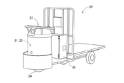
本発明に係るバッテリ装置は、例えば、図1に示すような電動運搬車で使用される。同図に示すように、電動運搬車20の運転席にはハンドル23が備えられ、その下方には走行輪24が備えられている。運転者がハンドル23を操作すると、それに応じて走行輪24が旋回し、電動運搬車20の進行方向が変化する。また、運転席の足元には不図示のアクセルペダルが備えられており、運転者がこれを踏み込むと不図示の走行用モータが動作して走行輪24が駆動される。
The battery device according to the present invention is used in, for example, an electric vehicle as shown in FIG. As shown in the drawing, the driver's seat of the
運転席の後部にはバッテリ装置を収容(装着)するための接続ユニット30が備えられている。本実施例における接続ユニット30はふた付きのラックであり、上段と下段にそれぞれ2つのバッテリ装置を並べて装着することができるようになっている。後で詳細に説明するが、バッテリ装置は複数の端子を有し、接続ユニット30に収容(装着)されると、バッテリ装置の各端子と接続ユニット30側に設けられた対応する各端子とがそれぞれ電気的に接続される。当然ながら、装着されたバッテリ装置を接続ユニット30から取り外すこともできる。
A
図2は、実施例1に係るバッテリ装置である。バッテリ装置1Aは箱状の金属ケースを備え、装着方向奥側の端面(図2(A)参照)には接続ユニット30と接続するための種々の端子4、5、6A、7が設けられている。また、装着方向手前側の端面(図2(B)参照)には持ち運びの際に使用する取手が設けられている。
FIG. 2 illustrates a battery device according to the first embodiment. The
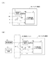
図3は、本実施例に係るバッテリ装置1Aのブロック図である。まず、図3(A)を参照して、バッテリ装置1Aは、二次電池部2と、監視部3(BMS)と、二次電池部2の正極に接続された正極出力端子4と、ヒューズ14を介して二次電池部2の負極に接続された負極出力端子5と、監視部3に接続された監視部電源入力端子6Aおよび異常検出端子7とを備える。
FIG. 3 is a block diagram of the
同図に示すように、正極出力端子4と二次電池部2の正極とは正極ライン10で接続され、負極出力端子5と二次電池部2の負極とは負極ライン11で接続されている。また、監視部3と監視部電源入力端子6Aとは監視部電源ライン12Aで接続されている。さらに、二次電池部2と監視部3とは、複数の配線からなる電池−監視部接続ライン13Aで接続されている。
As shown in the figure, the positive
二次電池部2に蓄積されている電力は、正極出力端子4および負極出力端子5から接続ユニット30に供給され、次いで電動運搬車20に供給される。なお、二次電池部2の充電は、充電装置に設けられた接続ユニット30を介して正極出力端子4と負極出力端子5との間に所定の直流電圧を印加することにより行われる。
The electric power stored in the
二次電池部2は、Liイオン単位電池を複数個直列に接続したものである。図4に示すように、通常、各Liイオン単位電池からは約3〜4Vが出力される。本実施例では、8個のLiイオン単位電池が直列に接続され、負極出力端子5の電圧を基準として正極出力端子4から接続ユニット30に向けて約24Vが出力されるようになっている。
The
監視部3は、各Liイオン単位電池の電圧や温度に基づいて、二次電池部2に過放電、過充電、発熱等の異常が発生していないかどうかを監視する。具体的には、監視部3は、各Liイオン単位電池の電圧が3.0V以下または4.2V以上となっていないかどうか(図4参照)、および各Liイオン単位電池の温度が通常の温度範囲を超えて上昇していないかどうかを監視する。そして、異常が発生していると判断した場合は、異常検出端子7を介してその旨を電動運搬車20側に通知する。当該通知を受けた電動運搬車20は、リレーを動作させる等してバッテリ装置1Aからの電力供給を停止し、発火や、過放電により二次電池部2が再使用不能となるのを防止する。
The
また、監視部3は、正側の電源ラインと負側の電源ラインとからなる一対の電源ラインを介して二次電池部2から電力供給されることにより、上記の動作をする。本実施例では負側の電源ラインは電池−監視部接続ライン13Aに含まれており、二次電池部2内で負極に接続されている。このため、監視部3には、負側の電源ラインを介して負極の電圧(基準電圧:例えば0V)が印加される。一方、本実施例では監視部電源ライン12Aが正側の電源ラインとなるが、このラインは監視部電源入力端子6Aにのみ接続され、二次電池部2の正極には接続されていない。したがって、バッテリ装置1A単体では監視部3に二次電池部2の正極の電圧(出力電圧:約24V)は印加されない。すなわち、バッテリ装置1A単体では監視部3に二次電池部2からの電力は供給されず、監視部3は上記の動作を行うことができない。
The
図3(B)は、本実施例に係るバッテリ装置1Aを電動運搬車20の接続ユニット30に装着した状態のブロック図である。同図に示すように、バッテリ装置1Aの正極出力端子4および負極出力端子5は、接続ユニット30を介して、主に走行用モータを駆動させるためのインバータ回路21に接続される。また、バッテリ装置1Aの異常検出端子7は、接続ユニット30を介して電動運搬車20の車体制御部22に接続される。
FIG. 3B is a block diagram of a state in which the battery device 1 </ b> A according to the present embodiment is mounted on the
接続ユニット30の内部には、監視部電源入力端子6Aと正極出力端子4とを接続するための正極バイパスライン31が備えられている。バッテリ装置1Aが接続ユニット30に装着されると、この正極バイパスライン31を介して監視部3の正側の電源ライン(監視部電源ライン12A)が二次電池部2の正極に接続される。また、前記の通り、監視部3の負側の電源ライン(電池−監視部接続ライン13A)は二次電池部2の負極に接続されている。つまり、バッテリ装置1Aが接続ユニット30に装着されると、監視部3の一対の電源ライン12A、13Aがそれぞれ二次電池部2の正極および負極に電気的に接続される。そして、監視部3に二次電池部2の電力が供給され、監視部3は二次電池部2を監視するべく動作可能になる。
In the
二次電池部2の電力が監視部3に供給され、かつ二次電池部2に異常がない場合、車体制御部22には、異常検出端子7を介して正常であることを示すHighレベルの信号が出力される。一方、二次電池部2に異常がある場合は、異常であることを示すLowレベルの信号が出力される。ここで、“Lowレベル”とは、例えば負極の電圧(0V)を意味する。また、“Highレベル”とは、例えば正極の電圧(24V)や当該電圧を降圧して得た電圧(5V等)を意味する。
When the power of the
また、バッテリ装置1Aが接続ユニット30に装着されていない等、二次電池部2から監視部3に電力供給がなされていない場合は、当然ながら異常検出端子7からはLowレベルの信号が出力されることになる。電力供給がなされていない状態では、Highレベルの信号を出力し得ないからである。
In addition, when the
異常検出端子7から出力される信号の極性を上記のようにすれば、監視部電源入力端子6Aにおける接触不良等のために動作に必要な十分な電力が監視部3に供給されていない場合に、異常が発生した際と同じLowレベルの信号が出力されることになる。このため、電動運搬車20の運転手は異常が発生している旨を知ることができ、バッテリ装置1Aを装着し直す等の適切な措置をとることができる。
When the polarity of the signal output from the
以上のように、本実施例に係るバッテリ装置1Aによれば、接続ユニット30に装着されていない未使用時(保管時)には、監視部3と二次電池部2との間の電気的な接続が遮断されているので、二次電池部2から監視部3への電力供給がなされない。このため、バッテリ装置1Aは、長期間に亘って保管されても、二次電池部2が過放電状態になって再使用不能となることはない。
As described above, according to the
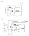
図5に、実施例2に係るバッテリ装置1Bのブロック図を示す。図5(A)に示すように、バッテリ装置1Bは、監視部電源入力端子6Aの替わりに監視部電源入力端子6Bを備える。そして、この監視部電源入力端子6Bは、負側の電源ラインである監視部電源ライン12Bで監視部3に接続されている。また、正側の電源ラインは電池−監視部接続ライン13Bに含まれており、二次電池部2内で正極に接続されている。
FIG. 5 is a block diagram of the battery device 1B according to the second embodiment. As shown in FIG. 5A, the battery device 1B includes a monitoring unit
すなわち、本実施例において、監視部3には、正側の電源ラインを介して正極の電圧(出力電圧:約24V)が印加される。一方、負側の電源ラインは監視部電源入力端子6Bにのみ接続され、二次電池部2の負極には接続されていない。したがって、バッテリ装置1B単体では監視部3に二次電池部2の負極の電圧(基準電圧:0V)は印加されず、監視部3は動作することができない。
That is, in this embodiment, a positive voltage (output voltage: about 24 V) is applied to the
図5(B)は、本実施例に係るバッテリ装置1Bを電動運搬車20の接続ユニット30に装着した状態のブロック図である。同図に示すように、接続ユニット30の内部には、監視部電源入力端子6Bと負極出力端子5とを接続するための負極バイパスライン32が備えられている。バッテリ装置1Bが接続ユニット30に装着されると、この負極バイパスライン32を介して監視部3の負側の電源ライン(監視部電源ライン12B)が二次電池部2の負極に接続される。これにより、監視部3の一対の電源ライン12B、13Bがそれぞれ二次電池部2の正極および負極に電気的に接続され、監視部3は二次電池部2を監視するべく動作可能になる。
FIG. 5B is a block diagram of a state where the battery device 1 </ b> B according to the present embodiment is mounted on the
図6に、実施例3に係るバッテリ装置1Cのブロック図を示す。図6(A)に示すように、バッテリ装置1Cは、正側の電源ラインである監視部電源ライン12Aで監視部3に接続された監視部電源入力端子6Aと、負側の電源ラインである監視部電源ライン12Bで監視部3に接続された監視部電源入力端子6Bとを備える。また、本実施例では、電池−監視部接続ライン13Cの中に監視部3の電源ラインは含まれていない。
FIG. 6 is a block diagram of a battery device 1C according to the third embodiment. As shown in FIG. 6A, the battery device 1C is a monitoring unit
すなわち、図6(A)に示す状態では、監視部3には、二次電池部2の正極の電圧(出力電圧:約24V)および負極の電圧(基準電圧:0V)はいずれも印加されず、監視部3は動作することができない。
That is, in the state shown in FIG. 6A, neither the positive voltage (output voltage: about 24 V) nor the negative voltage (reference voltage: 0 V) of the
図6(B)は、本実施例に係るバッテリ装置1Cを電動運搬車20の接続ユニット30に装着した状態のブロック図である。同図に示すように、接続ユニット30の内部には、監視部電源入力端子6Aと正極出力端子4とを接続するための正極バイパスライン31と、監視部電源入力端子6Bと負極出力端子5とを接続するための負極バイパスライン32とが備えられている。バッテリ装置1Cが接続ユニット30に装着されると、この2つのバイパスライン31、32を介して監視部3の一対の電源ライン12A、12Bが二次電池部2の正極および負極に接続される。これにより、監視部3に二次電池部2の電力が供給され、監視部3は二次電池部2を監視するべく動作可能になる。
FIG. 6B is a block diagram of a state in which the battery device 1 </ b> C according to the present embodiment is mounted on the
以上、本発明に係るバッテリ装置の好ましい実施形態について説明したが、本発明は上記の構成に限定されるものではない。例えば、二次電池部2はLiイオン電池に限らず、ニッケル水素充電池等の他の二次電池とすることができる。
As mentioned above, although preferable embodiment of the battery apparatus which concerns on this invention was described, this invention is not limited to said structure. For example, the
1A、1B、1C バッテリ装置
2 二次電池部
3 監視部
4 正極出力端子
5 負極出力端子
6A、6B 監視部電源入力端子
7 異常検出端子
10 正極ライン
11 負極ライン
12A、12B 監視部電源ライン
13A、13B、13C 電池−監視部接続ライン
14 ヒューズ
30 接続ユニット
31 正極バイパスライン
32 負極バイパスライン
1A, 1B,
Claims (4)
二次電池部と、
前記二次電池部の正極および負極と前記接続ユニットとをそれぞれ電気的に接続するための2つの出力端子と、
一対の電源ラインによって電力供給されるようになっており、前記一対の電源ラインの正側が前記正極に電気的に接続され、かつ前記一対の電源ラインの負側が前記負極に電気的に接続されると前記二次電池部を監視するべく動作する監視部と、
前記監視部に一端が接続された前記一対の電源ラインの少なくとも一方の他端を前記接続ユニットに電気的に接続するための1つまたは2つの監視部電源入力端子と、
を備え、
前記接続ユニットの内部には、前記監視部電源入力端子と前記出力端子とを接続するための1つまたは2つのバイパスラインが設けられており、前記接続ユニットに装着されると、前記バイパスラインを経由して前記一対の電源ラインの少なくとも一方が前記正極および/または負極に電気的に接続されることを特徴とするバッテリ装置。 A cassette-type battery device that can be attached to and detached from a connection unit provided in a vehicle,
A secondary battery section;
Two output terminals for electrically connecting the positive and negative electrodes of the secondary battery unit and the connection unit, respectively;
Power is supplied by a pair of power supply lines, the positive side of the pair of power supply lines is electrically connected to the positive electrode, and the negative side of the pair of power supply lines is electrically connected to the negative electrode. And a monitoring unit that operates to monitor the secondary battery unit,
One or two monitoring unit power input terminals for electrically connecting at least one other end of the pair of power supply lines, one end of which is connected to the monitoring unit, to the connection unit;
With
Inside the connection unit, one or two bypass lines for connecting the monitoring unit power input terminal and the output terminal are provided, and when the connection unit is attached, the bypass line is connected to the connection unit. At least one of the pair of power supply lines is electrically connected to the positive electrode and / or the negative electrode via the battery device.
前記バイパスラインは、前記正極に接続された前記出力端子と前記監視部電源入力端子とを接続するものであり、
前記一対の電源ラインの負側と前記負極とは、前記接続ユニットを経由することなく電気的に接続されていることを特徴とする請求項1に記載のバッテリ装置。 The monitoring unit power input terminal is connected to the other end on the positive side of the pair of power supply lines,
The bypass line connects the output terminal connected to the positive electrode and the monitoring unit power input terminal,
The battery device according to claim 1, wherein the negative side of the pair of power supply lines and the negative electrode are electrically connected without passing through the connection unit.
前記バイパスラインは、前記負極に接続された前記出力端子と前記監視部電源入力端子とを接続するものであり、
前記一対の電源ラインの正側と前記正極とは、前記接続ユニットを経由することなく電気的に接続されていることを特徴とする請求項1に記載のバッテリ装置。 The monitoring unit power input terminal is connected to the other end on the negative side of the pair of power supply lines,
The bypass line connects the output terminal connected to the negative electrode and the monitoring unit power input terminal,
The battery device according to claim 1, wherein the positive side of the pair of power supply lines and the positive electrode are electrically connected without passing through the connection unit.
前記異常検出端子からは、
前記接続ユニットに接続されており、かつ前記二次電池部に異常がない場合は、正常であることを示すHighレベルの信号が出力され、
前記接続ユニットに装着されておらず前記監視部が動作していない場合、および前記接続ユニットに装着されてはいるが前記二次電池部に異常がある場合は、異常であることを示すLowレベルの信号が出力される、
ことを特徴とする請求項1〜3のいずれかに記載のバッテリ装置。 Further comprising an abnormality detection terminal connected to the monitoring unit,
From the abnormality detection terminal,
When connected to the connection unit and there is no abnormality in the secondary battery unit, a high level signal indicating normal is output,
Low level indicating that there is an abnormality when the connection unit is not attached and the monitoring unit is not operating, and when the connection unit is attached but there is an abnormality in the secondary battery unit Is output,
The battery device according to any one of claims 1 to 3.
Priority Applications (1)
| Application Number | Priority Date | Filing Date | Title |
|---|---|---|---|
| JP2009263537A JP2011108536A (en) | 2009-11-19 | 2009-11-19 | Cassette battery device |
Applications Claiming Priority (1)
| Application Number | Priority Date | Filing Date | Title |
|---|---|---|---|
| JP2009263537A JP2011108536A (en) | 2009-11-19 | 2009-11-19 | Cassette battery device |
Publications (1)
| Publication Number | Publication Date |
|---|---|
| JP2011108536A true JP2011108536A (en) | 2011-06-02 |
Family
ID=44231784
Family Applications (1)
| Application Number | Title | Priority Date | Filing Date |
|---|---|---|---|
| JP2009263537A Pending JP2011108536A (en) | 2009-11-19 | 2009-11-19 | Cassette battery device |
Country Status (1)
| Country | Link |
|---|---|
| JP (1) | JP2011108536A (en) |
Cited By (1)
| Publication number | Priority date | Publication date | Assignee | Title |
|---|---|---|---|---|
| JP2020089194A (en) * | 2018-11-29 | 2020-06-04 | 東洋システム株式会社 | Battery pack |
Citations (11)
| Publication number | Priority date | Publication date | Assignee | Title |
|---|---|---|---|---|
| JPH07245095A (en) * | 1994-03-08 | 1995-09-19 | Sony Corp | Removable type battery unit |
| JPH0883627A (en) * | 1994-07-13 | 1996-03-26 | Taiyo Yuden Co Ltd | Overdischarging preventing method for secondary battery, charging/discharging control circuit, and battery pack |
| JPH1028334A (en) * | 1996-07-11 | 1998-01-27 | Saitama Nippon Denki Kk | Secondary battery pack and charging/discharging system |
| JPH11225444A (en) * | 1997-10-28 | 1999-08-17 | Hewlett Packard Co <Hp> | Battery pack |
| JPH11339862A (en) * | 1998-05-29 | 1999-12-10 | Sanyo Electric Co Ltd | Packed battery and its shipping method |
| JP2002208443A (en) * | 2001-01-11 | 2002-07-26 | Sanyo Electric Co Ltd | Battery pack |
| JP2004206894A (en) * | 2002-12-24 | 2004-07-22 | Nec Tokin Tochigi Ltd | Battery pack with built-in protection circuit |
| JP2007116853A (en) * | 2005-10-21 | 2007-05-10 | Hitachi Koki Co Ltd | Lithium battery pack |
| JP2007128696A (en) * | 2005-11-02 | 2007-05-24 | Gs Yuasa Corporation:Kk | Battery pack for electric apparatus |
| JP2008271690A (en) * | 2007-04-19 | 2008-11-06 | Nec Tokin Corp | Secondary battery pack |
| JP2009112111A (en) * | 2007-10-30 | 2009-05-21 | Toshiba Corp | Battery pack, charger, and battery pack system |
-
2009
- 2009-11-19 JP JP2009263537A patent/JP2011108536A/en active Pending
Patent Citations (11)
| Publication number | Priority date | Publication date | Assignee | Title |
|---|---|---|---|---|
| JPH07245095A (en) * | 1994-03-08 | 1995-09-19 | Sony Corp | Removable type battery unit |
| JPH0883627A (en) * | 1994-07-13 | 1996-03-26 | Taiyo Yuden Co Ltd | Overdischarging preventing method for secondary battery, charging/discharging control circuit, and battery pack |
| JPH1028334A (en) * | 1996-07-11 | 1998-01-27 | Saitama Nippon Denki Kk | Secondary battery pack and charging/discharging system |
| JPH11225444A (en) * | 1997-10-28 | 1999-08-17 | Hewlett Packard Co <Hp> | Battery pack |
| JPH11339862A (en) * | 1998-05-29 | 1999-12-10 | Sanyo Electric Co Ltd | Packed battery and its shipping method |
| JP2002208443A (en) * | 2001-01-11 | 2002-07-26 | Sanyo Electric Co Ltd | Battery pack |
| JP2004206894A (en) * | 2002-12-24 | 2004-07-22 | Nec Tokin Tochigi Ltd | Battery pack with built-in protection circuit |
| JP2007116853A (en) * | 2005-10-21 | 2007-05-10 | Hitachi Koki Co Ltd | Lithium battery pack |
| JP2007128696A (en) * | 2005-11-02 | 2007-05-24 | Gs Yuasa Corporation:Kk | Battery pack for electric apparatus |
| JP2008271690A (en) * | 2007-04-19 | 2008-11-06 | Nec Tokin Corp | Secondary battery pack |
| JP2009112111A (en) * | 2007-10-30 | 2009-05-21 | Toshiba Corp | Battery pack, charger, and battery pack system |
Cited By (1)
| Publication number | Priority date | Publication date | Assignee | Title |
|---|---|---|---|---|
| JP2020089194A (en) * | 2018-11-29 | 2020-06-04 | 東洋システム株式会社 | Battery pack |
Similar Documents
| Publication | Publication Date | Title |
|---|---|---|
| JP5939496B2 (en) | Battery control apparatus and method {Batterymanagementapparatusandmethod} | |
| US9112216B2 (en) | Apparatus and method for managing battery pack | |
| JP5854242B2 (en) | Electric power supply device using electric vehicle | |
| JP6872549B2 (en) | Current measuring device using shunt resistor | |
| JP7259745B2 (en) | Power storage device, vehicle, motorcycle | |
| JP6111848B2 (en) | Power storage system | |
| US20170021739A1 (en) | Straddled electric vehicle, and charging system for straddled electric vehicle | |
| JP6694548B2 (en) | Fuse diagnostic device and method using voltage distribution | |
| JP6107562B2 (en) | Battery control unit system | |
| JP6087675B2 (en) | Battery module | |
| JP2011078184A (en) | Power supply unit for vehicle, and vehicle mounted with the power supply unit | |
| JP5704146B2 (en) | Power storage system | |
| JP2009204531A (en) | Shunt resistor, and power supply device for vehicle equipped with the shunt resistor | |
| JP2008166025A (en) | Battery pack and battery module as well as hybrid car using it | |
| JP2011108537A (en) | Cassette battery device | |
| US20150004443A1 (en) | Apparatus for controlling lithium-ion battery and method of recovering lithium-ion battery | |
| JP2010110033A (en) | Device for determining abnormality in storage capacitor, and device for determining abnormality in vehicle and storage element | |
| JP5978143B2 (en) | Battery system | |
| KR20160026734A (en) | Electric power supply device | |
| JP2011108536A (en) | Cassette battery device | |
| WO2004034074A1 (en) | Battery managing metod and device | |
| JP2020150629A (en) | Dc feeder circuit for work vehicle | |
| JP6636793B2 (en) | Battery pack | |
| JP6647839B2 (en) | Energy storage system | |
| JP6269434B2 (en) | vehicle |
Legal Events
| Date | Code | Title | Description |
|---|---|---|---|
| A977 | Report on retrieval |
Free format text: JAPANESE INTERMEDIATE CODE: A971007 Effective date: 20120601 |
|
| A131 | Notification of reasons for refusal |
Free format text: JAPANESE INTERMEDIATE CODE: A131 Effective date: 20120718 |
|
| A02 | Decision of refusal |
Free format text: JAPANESE INTERMEDIATE CODE: A02 Effective date: 20130109 |