JP2011027595A - Map data verification system - Google Patents
Map data verification system Download PDFInfo
- Publication number
- JP2011027595A JP2011027595A JP2009174637A JP2009174637A JP2011027595A JP 2011027595 A JP2011027595 A JP 2011027595A JP 2009174637 A JP2009174637 A JP 2009174637A JP 2009174637 A JP2009174637 A JP 2009174637A JP 2011027595 A JP2011027595 A JP 2011027595A
- Authority
- JP
- Japan
- Prior art keywords
- map data
- error
- vehicle
- distance
- measurement
- Prior art date
- Legal status (The legal status is an assumption and is not a legal conclusion. Google has not performed a legal analysis and makes no representation as to the accuracy of the status listed.)
- Withdrawn
Links
Images


Landscapes
- Instructional Devices (AREA)
- Navigation (AREA)
- Traffic Control Systems (AREA)
Abstract
Description
本発明は、地図データが現実と一致するか否かを検証する技術に関する。 The present invention relates to a technique for verifying whether map data matches reality.
カーナビゲーション装置における地図データの高鮮度化を図るために、地図配信の仕組みなどが整備されている(特許文献1、2など)。ところで、地図データの鮮度を上げるためには、現地調査の頻度を上げなければならないが、更新頻度にも限界があり常に最新の地図データを配信することは困難である。
In order to improve the freshness of the map data in the car navigation device, a map distribution mechanism and the like have been prepared (
特許文献3には、自車位置の測定精度を向上させるために車載カメラ画像からランドマークを認識して補正に用いること、および、認識したランドマークが内蔵された地図データと異なる場合に、地図配信センターに地図データの更新情報を送ったり、地図配信センターから最新の地図データを取得したりすることが記載されている。特許文献3では、認識結果の確からしさや画像の撮影条件などを考慮した上で、内蔵された地図データが現実と異なる旨の報告を地図配信センターにしている。
In
カーナビゲーション装置の有する地図データが古くなり実際のデータと異なる場合には、できるだけ早期に、その箇所を検出できることが好ましい。本発明の目的は、地図データと現実世界の地物との違いを短時間で検出することにある。 When the map data possessed by the car navigation device is old and different from the actual data, it is preferable that the location can be detected as early as possible. An object of the present invention is to detect a difference between map data and real-world features in a short time.
上記目的を達成するために本発明では、地図データと現実世界の地物との違いの検出を、以下の手段または処理によって行う。 In order to achieve the above object, in the present invention, the difference between the map data and the real world features is detected by the following means or processing.
本発明に係る地図データ検証システムは、自車両の位置を検出する位置検出手段と、道路および地物のデータを格納した地図データと、道路の脇に存在する地物までの距離を測定する測距手段と、測距手段によって測定された距離が自車両位置および地図データから予測される値と異なる箇所(エラー箇所)を検出するエラー検出手段を有する。さらに、本発明に係る地図データ検証システムは、地図データのエラー箇所の情報をエラー情報として他の車両に送信するとともに、他の車両から送信されるエラー情報を受信する通信手段とを有する。 The map data verification system according to the present invention includes position detection means for detecting the position of the host vehicle, map data storing road and feature data, and measurement for measuring the distance to the feature located beside the road. Distance means and error detection means for detecting a location (error location) where the distance measured by the distance measurement means is different from a value predicted from the vehicle position and map data. Furthermore, the map data verification system according to the present invention includes communication means for transmitting error information of map data to other vehicles as error information and receiving error information transmitted from other vehicles.
測距手段としては、レーザースキャナや、ステレオカメラを用いることができる。レーザースキャナは、計測対象物とセンサーとの間をレーザーパルスが往復する時間を計測することで、計測対象物までの距離を測定する。レーザースキャナは、たとえば、車両の斜め前方向き(左前方および右前方)に固定すれば、車両の移動とともに道路脇に存在する物体までの距離を計測できる。レーザースキャナは垂直方向に所定の周波数(たとえば数十〜数百ヘルツ)で走査するが、垂直方向に走査しなくても良い。ステレオカメラは、2つのカメラから撮影される画像の視差に基づいて計測対象物までの距離を測定する。ステ
レオカメラの場合は、1回の撮影で、撮影対象物の全てについての距離が測定可能である。
As the distance measuring means, a laser scanner or a stereo camera can be used. The laser scanner measures the distance to the measurement object by measuring the time for the laser pulse to reciprocate between the measurement object and the sensor. For example, if the laser scanner is fixed obliquely forward (left front and right front) of the vehicle, the distance to an object existing on the roadside can be measured as the vehicle moves. The laser scanner scans in the vertical direction at a predetermined frequency (for example, several tens to several hundreds hertz), but may not scan in the vertical direction. The stereo camera measures the distance to the measurement object based on the parallax of images taken from the two cameras. In the case of a stereo camera, it is possible to measure the distance for all of the objects to be photographed by one photographing.
地図データは、3次元地図データであることが好ましい。すなわち、道路や地物の3次元形状が格納されていることが好ましい。ただし、2次元地図データであっても、道路の情報以外に、地物の平面形状や、地物と道路との間の距離が含まれていれば本発明において利用可能である。すなわち、道路上の任意の点とその地物との間の距離が算出可能なデータが含まれていれば良い。なお、地物とは地上に存在する物体のうち、移動体を除き、地表において位置が固定されている非移動体を意味する。地物は人工物であっても自然物であっても良く、人工物にはたとえば、建築物、各種施設、橋、鉄道などが含まれ、自然物にはたとえば、山、海、河川などが含まれる。 The map data is preferably three-dimensional map data. That is, it is preferable to store a three-dimensional shape of a road or a feature. However, even two-dimensional map data can be used in the present invention as long as the plane shape of the feature and the distance between the feature and the road are included in addition to the road information. That is, it is only necessary to include data capable of calculating the distance between an arbitrary point on the road and the feature. The feature means a non-moving body whose position is fixed on the ground surface except for a moving body among objects existing on the ground. The feature may be an artifact or a natural object, and the artifact includes, for example, a building, various facilities, a bridge, and a railway, and the natural object includes, for example, a mountain, a sea, a river, and the like. .
自車両の位置は位置検出手段によって検出できる。位置検出手段は、典型的にはGPS装置であるが、加速度センサーやジャイロセンサーを利用して自車両の位置情報を補完的に求めても良い。また、位置検出には、GPS以外の無線通信、道路に埋め込まれたマーカー(磁気マーカー、画像マーカーなど)などを用いても良い。また、自車両の位置の履歴から走行方向も検出可能である。 The position of the host vehicle can be detected by position detection means. The position detection means is typically a GPS device, but the position information of the host vehicle may be obtained complementarily using an acceleration sensor or a gyro sensor. For position detection, wireless communication other than GPS, markers embedded in roads (magnetic markers, image markers, etc.) may be used. The traveling direction can also be detected from the history of the position of the host vehicle.
自車両の位置および走行方向が分かると、測距手段による測定方向に位置する地物までの距離を地図データから算出可能である。地図データから算出される地物までの距離と、実際に測距手段によって測定される地物までの距離が異なる場合は、地図データが現実と異なることが分かる。具体的には、地図データによると道路の脇近くに地物があるにもかかわらず、測距手段による測定距離が予測値よりも大きい場合には、地図データには存在するとされている地物が消滅したと判断できる。一方、地図データには道路の脇近くには地物が無く、したがって、より遠くの地物までの距離が測定される判断されるにもかかわらず、測距手段による測定距離が短い場合には、その位置に新たに地物が生成されたと判断できる。このように、エラー検出手段は、地図データにエラーのある箇所(エラー箇所と呼ぶ)を検出可能である。 If the position and traveling direction of the host vehicle are known, the distance to the feature located in the measurement direction by the distance measuring means can be calculated from the map data. When the distance to the feature calculated from the map data and the distance to the feature actually measured by the distance measuring means are different, it is understood that the map data is different from the actual. Specifically, according to the map data, if there is a feature near the side of the road, but the measured distance by the distance measuring means is larger than the predicted value, the feature that is supposed to exist in the map data Can be determined to have disappeared. On the other hand, if there is no feature near the side of the road in the map data, and the distance to the farther feature is determined to be measured, but the distance measured by the distance measuring means is short, , It can be determined that a new feature has been generated at that position. As described above, the error detection means can detect a location where the map data has an error (referred to as an error location).
なお、測距手段による地物までの距離の測定は、ある程度の測定期間(たとえば車両が数メートル進む間の時間)の、平均測定距離を採用しても良い。一点のみによる測定では誤差の影響があったり、障害物までの距離を測定することもあり得るからである。また、測距手段としてレーザースキャナを用いて垂直方向にも走査する場合、走査周波数に比較して車両の速度が遅ければ地物の3次元形状を測定可能である。地図データも3次元である場合には、地図データ中の地物の形状と測定結果を比較して同一の地物であるか否かを判断して、地図データにエラーがあるが判断しても良い。 Note that the measurement of the distance to the feature by the distance measuring means may employ an average measurement distance during a certain measurement period (for example, the time during which the vehicle travels several meters). This is because the measurement using only one point may be affected by an error or may measure the distance to an obstacle. Further, when scanning in the vertical direction using a laser scanner as a distance measuring means, if the vehicle speed is slower than the scanning frequency, the three-dimensional shape of the feature can be measured. If the map data is also three-dimensional, compare the shape of the features in the map data with the measurement results to determine whether they are the same feature, and determine if there is an error in the map data Also good.
エラー検出手段によって検出されたエラー箇所の情報は、通信手段によって周囲の車両にエラー情報として送信される。このような通信手段(車車間通信手段)には、無線LANやDSRC(専用狭域通信)などの無線通信や、可視光通信や赤外光通信などの光通信を採用できる。このように車車間通信によってエラー箇所の情報を車両間で共有するため、各車両は、自車両で測定して検出できるエラー箇所だけでなく、他の車両が検出したエラー箇所の情報も取得できる。すなわち、多くのエラー箇所を短時間に収集することができる。これにより、地図データが現実と異なる箇所を短時間で検出可能である。 The information on the error location detected by the error detection means is transmitted as error information to surrounding vehicles by the communication means. For such communication means (vehicle-to-vehicle communication means), wireless communication such as wireless LAN or DSRC (dedicated narrow area communication), or optical communication such as visible light communication or infrared light communication can be employed. In this way, the information on the error location is shared between vehicles by inter-vehicle communication, so that each vehicle can acquire not only the error location that can be measured and detected by the own vehicle, but also information on the error location detected by other vehicles. . That is, many error locations can be collected in a short time. Thereby, the location where map data differs from reality can be detected in a short time.
測距手段として、レーザースキャナやステレオカメラを利用することができる。レーザースキャナは照明による影響はあまり受けないが、降雨時には雨滴による影響を受け測定性能が低下する。したがって、降雨時にはレーザースキャナによる測定を行わないか、または、降雨時の測定であることをエラー情報に加えることが好ましい。雨が降っているか否かは、たとえば、ワイパーが動作しているか否かによって判断しても良いし、天気に関
する情報を無線通信などによって取得して判断しても良い。また、測距手段としてステレオカメラを利用する場合は、日中の測定性能は良好であるが、それ以外(夜間等)は測定性能が低下する。したがって、日中以外にはステレオカメラによる測定を行わないか、または、日中以外の測定であることをエラー情報に加えることが好ましい。ここで、日中として、たとえば、日出および日没時刻を基準として、日出1時間後から日没1時間前の間として定義することができる。
A laser scanner or a stereo camera can be used as the distance measuring means. Laser scanners are not significantly affected by illumination, but at the time of rainfall, they are affected by raindrops and the measurement performance is degraded. Therefore, it is preferable not to perform the measurement by the laser scanner at the time of rain, or to add to the error information that the measurement is at the time of rain. Whether or not it is raining may be determined by, for example, whether or not the wiper is operating, or may be determined by acquiring information related to the weather by wireless communication or the like. Further, when a stereo camera is used as the distance measuring means, the measurement performance during the day is good, but the measurement performance is degraded in other cases (such as at night). Therefore, it is preferable not to perform the measurement by the stereo camera except during the daytime or to add to the error information that the measurement is other than during the daytime. Here, the daytime can be defined as, for example, between 1 hour after sunrise and 1 hour before sunset with reference to sunrise and sunset times.
本発明において、自車両が検出した地図データのエラー箇所や、他の車両から送信される地図データのエラー箇所の情報を、エラー判定の信頼度とともに記憶する記憶手段をさらに備えることが好ましい。ここで、エラー判定の信頼度とは、地図データの情報と実際の測定とが異なるという判断が信頼できる確かさをいう。たとえば、測距手段による測定精度を信頼度として利用することができる。上述のように、測距手段がレーザースキャナの場合は、晴天時の測定に基づくエラー判定の方が、降雨時の測定に基づくエラー判定よりも信頼度が高い。測距手段がステレオカメラの場合に、日中の測定に基づくエラー判定の方が、夜間(日中以外)の測定に基づくエラー判定よりも信頼度が高い。 In the present invention, it is preferable to further include storage means for storing information on the error location of the map data detected by the host vehicle and the error location of the map data transmitted from another vehicle together with the reliability of the error determination. Here, the reliability of the error determination refers to the reliability with which the determination that the information of the map data is different from the actual measurement is reliable. For example, the measurement accuracy by the distance measuring means can be used as the reliability. As described above, when the distance measuring means is a laser scanner, the error determination based on the measurement in the fine weather has higher reliability than the error determination based on the measurement in the rain. When the distance measuring means is a stereo camera, the error determination based on the daytime measurement has higher reliability than the error determination based on the nighttime (other than daytime) measurement.
また、多くの車両によってエラー判定されている箇所は、そのエラー判定の信頼度を高いものと判断できる。したがって、多くの車両からエラー情報として送信されるエラー箇所についてのエラー判定の信頼度は高いものと判断できる。 In addition, it can be determined that the error determination reliability is high at a location where an error is determined by many vehicles. Therefore, it can be determined that the reliability of the error determination for the error portion transmitted as error information from many vehicles is high.
また、同一の箇所について、異なる方向に走行する車両からエラーであると判定された箇所は、そのエラー判定の信頼度を高いものと判断できる。そのために、エラー情報を他の車両に送信する際に、このエラー箇所の距離測定を行ったときの自車両の走行方向をあわせて送信することが好ましい。 In addition, it is possible to determine that a part determined to be an error from a vehicle traveling in a different direction with respect to the same part has a high reliability of the error determination. Therefore, when transmitting error information to another vehicle, it is preferable that the traveling direction of the host vehicle when the distance measurement of the error location is performed is also transmitted.
また、エラー箇所の距離測定を行ったときの、エラー箇所と自車両との距離が短いほど、距離測定の精度が高く、したがってエラー判定の信頼度が高いと判断できる。そのために、エラー情報を他の車両に送信する際に、このエラー箇所の距離測定を行った際のエラー箇所と自車両との間の距離をあわせて送信することが好ましい。 Further, it can be determined that the shorter the distance between the error location and the host vehicle when the error location is measured, the higher the accuracy of the distance measurement, and thus the higher the reliability of the error determination. Therefore, when transmitting error information to another vehicle, it is preferable to transmit the distance between the error location and the own vehicle when the distance measurement of the error location is performed.
なお、本発明は、上記手段の少なくとも一部を有する地図データ検証システムとして捉えることができる。また、本発明は、上記処理の少なくとも一部を含む地図データ検証方法、または、かかる方法を実現するためのプログラムとして捉えることもできる。上記手段および処理の各々は可能な限り互いに組み合わせて本発明を構成することができる。 The present invention can be understood as a map data verification system having at least a part of the above means. Moreover, this invention can also be grasped | ascertained as the map data verification method containing at least one part of the said process, or the program for implement | achieving this method. Each of the above means and processes can be combined with each other as much as possible to constitute the present invention.
本発明によれば、地図データと現実世界の地物との違いを短時間で検出できる。 According to the present invention, a difference between map data and real world features can be detected in a short time.
以下に図面を参照して、この発明の好適な実施の形態を例示的に詳しく説明する。なお、以下では地物が建築物である例を用いて説明を行うが、地物は建築物以外のものであっても構わない。 Exemplary embodiments of the present invention will be described in detail below with reference to the drawings. In the following description, an example in which a feature is a building will be described, but the feature may be other than a building.
(概要)
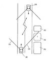
図1は本実施形態に係る地図データ検証システムの概略を説明する図である。図中上方向に走行する車両100は、符号101,102の示す方向を対象にレーザースキャナによる距離測定を行いながら走行する。距離測定を行う方向は、車両の斜め前方であり、道路脇に存在する建築物までの距離を測定可能である。車両100は、ナビゲーション用に地図データを有している。この地図データには道路のデータ以外に、建築物のデータも含まれる。したがって、自車両の位置が分かると、測定方向101,102に存在する建築物までの距離が地図データから予測可能である。地図データから予測される距離と、レーザースキャナによる実際の測定距離とが異なる場合は、地図データが現実と異なることが分かる。たとえば、地図データには建築物301,302,303が存在しているが、実際には建築物302が取り壊されている状況を考える。図に示すように車両100の測定方向101が建築物302の方向と一致する場合、測定方向101についての実際の測定距離は建築物303までの距離となり、地図データから予測される距離よりも長いため、建築物302が消滅したことが分かる。つまり、車両100は地図データに含まれる建築物302が消滅したことが分かる。逆に、地図データには建築物が存在しない場所に新たに建築物ができた場合も、レーザースキャナによる測定距離が地図データから予測される距離と異なるため、建築物の生成を把握可能である。車両100は、このように地図データが現実を反映していない箇所(エラー箇所)を検出すると、エラー箇所の情報を他の車両200に車車間通信によって通知する。この情報を受け取った車両200では、地図データが誤っている旨の表示を行ったりすることができる。
(Overview)
FIG. 1 is a diagram for explaining the outline of a map data verification system according to this embodiment. A
(機能構成)
図2は、本実施形態における車載装置の機能構成を示す図である。レーザースキャナ1は、レーザーパルスを照射し、その反射パルスが帰ってくるまでの時間を計測することで、計測対象物までの距離を計測する。本実施形態では、レーザースキャナ1を利用して、自車両と道路の脇に存在している建築物までの距離を計測する。レーザースキャナ1は車両に2つ搭載され、それぞれ左斜め前方および右斜め前方に向けられている。測定方向の水平面内方向は固定されているが、垂直方向には所定の角度範囲で走査する。たとえば、0度(水平)から70度の範囲を走査周波数100Hzで走査する。もちろん、走査角度の範囲や走査周波数は適宜設定可能である。走査角度の範囲を大きくするほど、より高い位置に存在する建築物までの距離を測定可能である。また、走査周波数が高いほど分解能の高い測定が可能であり、建築物の詳細な3次元形状を取得可能である。計測対象物の距離と車両の移動速度によっても変化するが、距離10m、時速50km、走査周波数100Hzであれば10〜20cm程度の間隔で計測できる。
(Functional configuration)
FIG. 2 is a diagram illustrating a functional configuration of the in-vehicle device according to the present embodiment. The laser scanner 1 measures the distance to the measurement object by irradiating the laser pulse and measuring the time until the reflected pulse returns. In the present embodiment, the laser scanner 1 is used to measure the distance between the vehicle and a building that is located on the side of the road. Two laser scanners 1 are mounted on the vehicle and are directed diagonally left frontward and diagonally forward right. Although the horizontal direction in the measurement direction is fixed, scanning is performed in a predetermined angular range in the vertical direction. For example, a range from 0 degrees (horizontal) to 70 degrees is scanned at a scanning frequency of 100 Hz. Of course, the range of scanning angles and the scanning frequency can be set as appropriate. As the range of the scanning angle is increased, the distance to the building existing at a higher position can be measured. In addition, the higher the scanning frequency, the higher the resolution can be measured, and the more detailed three-dimensional shape of the building can be acquired. Although it varies depending on the distance of the measurement object and the moving speed of the vehicle, if the distance is 10 m, the speed is 50 km, and the scanning frequency is 100 Hz, the measurement can be performed at intervals of about 10 to 20 cm.
なお、レーザースキャナ1の設置条件は上記のものに限定されない。たとえば、レーザースキャナの測定方向は斜め前方に限定されず、横方向や斜め後方であっても構わない。また、レーザースキャナの数は2つである必要はなく、3つ以上利用しても良く、また1つのみのレーザースキャナで走査角度範囲を大きく(たとえば、180度以上)することで、道路の両側の建築物までの距離を計測できる。また、建築物の3次元形状を計測せずに車両と建築物との間の距離を測定するのであれば、走査を行わない測距センサーを用いても構わない。測距センサーとしてレーザー式以外にも赤外光や超音波などを用いて構わない。 The installation conditions of the laser scanner 1 are not limited to the above. For example, the measurement direction of the laser scanner is not limited to diagonally forward, and may be laterally or diagonally backward. The number of laser scanners does not have to be two, and three or more laser scanners may be used, and by increasing the scanning angle range (for example, 180 degrees or more) with only one laser scanner, The distance to the buildings on both sides can be measured. Further, if the distance between the vehicle and the building is measured without measuring the three-dimensional shape of the building, a distance measuring sensor that does not perform scanning may be used. As a distance measuring sensor, infrared light or ultrasonic waves may be used in addition to the laser type.
測距手段としてステレオカメラを用いても良い。ステレオカメラは、2つのカメラによって1対の画像を撮影し、視差に基づいて撮影対象物までの距離を算出する。ステレオカメラは毎秒数十〜百フレーム程度のフレーム速度で画像取得を行う。ステレオカメラを用いる場合もレーザースキャナと同様に、左斜め前方と右斜め前方を向いた2組のステレオカメラを用いることが好ましいが、これに限られるものではない。また、ステレオカメラ
の撮像素子(CCDやCMOSなど)は、夜間にも撮影可能なように、可視光領域だけでなく近赤外領域まで検出可能な撮像素子を用いても良い。
A stereo camera may be used as the distance measuring means. The stereo camera captures a pair of images with two cameras, and calculates the distance to the object to be imaged based on the parallax. Stereo cameras acquire images at a frame rate of several tens to hundreds of frames per second. In the case of using a stereo camera, it is preferable to use two sets of stereo cameras facing left diagonally forward and right diagonally forward as in the case of the laser scanner, but the present invention is not limited to this. In addition, as an imaging device (CCD, CMOS, etc.) of the stereo camera, an imaging device that can detect not only the visible light region but also the near infrared region may be used so that it can be photographed at night.
自車位置検出部2は、GPS装置3、ジャイロセンサー4、加速度センサー5などを利用して自車両の位置および走行方向を検出する。GPS装置3が受信するGPS衛星信号に基づいて自車両の絶対座標を取得するとともに、ジャイロセンサー4から得られる走行方向や加速度センサー5から得られる移動距離に基づいて補正を行うことで自車両の位置を精度良く検出できる。その他、地図データとのマッチング(マップマッチング)により位置補正を行っても良い。なお、自車両の位置検出は上記の構成によるものに限られず、無線通信による位置情報の取得、道路に埋め込まれた磁気マーカーの検知、カメラ画像の画像認識などの手段を併用して自車両の位置を検出しても良い。
The own vehicle
3次元地図データ6は、道路やその周辺の構造物の3次元形状を記憶する。エラー箇所検出部7は、3次元地図データ6が現実と異なる箇所を検出する。自車位置検出部2から得られる自車両の位置および走行方向と3次元地図データ6とから、現在の車両位置からレーザースキャナの測定方向にある建築物までの距離が算出できる。すなわち、地図データが正しい場合のレーザースキャナによる測定の予測値が算出できる。そこで、エラー箇所検出部7は、レーザースキャナ1による実測値と、自車両位置と地図データとから算出される予測値を比較して、これらが一致するか否かを判断することで、地図データが正しいか否か判定する。
The three-
距離測定の結果に基づいて地図データの正しさを判定する処理について、図3を参照してより詳細に説明する。図3は3次元地図データ6に含まれる地図の例を示す。たとえば、図3(a)に示すように、3次元地図データ6上では交差点付近に建築物51,52,53が存在している場合を考える。図中の車両Aのエラー箇所検出部7は、自車両の位置・走行方向および地図データに基づいて、左前方向きのレーザースキャナ1による測定の結果が距離61になるものと判断(予測)できる。車両Bも同様に、左前方向きのレーザースキャナ1による測定の結果は距離62になるものと判断できる。地図データが現実と一致する場合には、レーザースキャナによる実際の計測結果は、地図データから予測される距離61,62と等しくなる。
しかしながら、図3(b)に示すように、建築物51が消滅している場合は、車両A,Bからは本来見えないはずの建築物53、52との間の距離63、64が計測される。このように、3次元地図データ6に基づいて予測される測定値よりも、実際の測定結果の方が大きい場合は、建築物が消滅したと判断できる。
逆に、3次元地図データ6には建築物51が存在しないと記録されている場合は、車両A,Bはそれぞれ図3(b)の距離63,64が測定されると予測されるが、実際の計測結果としては距離61,62が得られる。このように、3次元地図データ6に基づいて予測される測定値よりも、実際の測定結果の方が小さい場合は、建築物が生成したと判断できる。
エラー箇所検出部7は以上のようにして、地図データに記録されているデータが現実と異なる箇所(エラー箇所)を検出する。
A process for determining the correctness of the map data based on the result of the distance measurement will be described in more detail with reference to FIG. FIG. 3 shows an example of a map included in the three-
However, as shown in FIG. 3B, when the
Conversely, if it is recorded in the
As described above, the
なお、レーザースキャナ1の測定方向に、他の車両や人物など地図データには含まれず一時的に現れる物体が存在する場合には、この物体までの距離が計測される。このような測定距離に基づく地図データの検証は誤検出につながるので、レーザースキャナによる計測結果が、自車両と道路脇(歩道も含む)との距離よりも小さい場合は、その測定結果を地図の検証に用いないことが好ましい。すなわち、レーザースキャナ1の測定方向について建築物が存在可能な領域までの最短距離を地図データから算出し、実際の測定結果が算出した最短距離よりも短い場合は、その計測を無効とする(エラー判定に利用しない)ことが好ましい。このようにすれば、一時的に存在する物体の影響を受けずに、地図データ
の検証を行える。
Note that when there is an object that temporarily appears in the measurement direction of the laser scanner 1 such as another vehicle or person and is not included in the map data, the distance to this object is measured. Verification of map data based on this measurement distance leads to false detection. If the measurement result by the laser scanner is smaller than the distance between the vehicle and the side of the road (including the sidewalk), the measurement result is displayed on the map. It is preferable not to use for verification. That is, the shortest distance to the area where the building can exist in the measurement direction of the laser scanner 1 is calculated from the map data, and if the actual measurement result is shorter than the calculated shortest distance, the measurement is invalidated (error (It is not used for determination). In this way, it is possible to verify the map data without being affected by the temporarily existing object.
エラー箇所を判定する際に、車両と対象物との距離以外の情報を用いても良い。たとえば、建築物の高さが一致するか否かを判定に利用しても良い。レーザースキャナによって垂直方向に走査している場合は建築物の高さを判断可能である。地図データに記録されている建築物の高さと、実際の測定による高さが異なる場合には、その位置に別の建築物が建てられたと判断することができる。また、レーザースキャナ1が分解能高く測定できる場合には、測定結果として得られる建築物の3次元形状が、地図データに含まれる建築物の3次元形状と一致するか否かによって、地図データが正しいか判断できる。 When determining the error location, information other than the distance between the vehicle and the object may be used. For example, it may be used for determination whether or not the heights of buildings match. When scanning vertically with a laser scanner, the height of the building can be determined. When the height of the building recorded in the map data is different from the actual height, it can be determined that another building has been built at that position. When the laser scanner 1 can measure with high resolution, the map data is correct depending on whether or not the three-dimensional shape of the building obtained as a measurement result matches the three-dimensional shape of the building included in the map data. Can be judged.
なお、ここでは地図データとして3次元地図データ6を利用することを想定しているが、建築物の3次元形状のマッチングによる地図データの検証を行わない場合は、2次元地図データを利用しても構わない。この場合、2次元地図データに、建築物の平面形状または道路脇からの距離などが含まれていれば、道路上の任意の点からその建築物までの距離を算出できるので、上記の判定が実行可能である。また、建築物の属性データとして高さが含まれていれば、高さを利用する判定も実行可能である。
Here, it is assumed that the
エラー箇所検出部7によって、現実と異なると判定された箇所に関する情報(エラー情報)は、エラー情報蓄積部8に蓄積される。なお、後述するように、エラー情報は他の車両に送信されるので、他の車両に通知すべき情報を格納しておくべきである。エラー情報蓄積部8には、自車が検出したエラー情報だけでなく、他の車両から通知されるエラー情報も格納する。
Information (error information) relating to a location determined to be different from the actual by the error
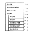
図4は、エラー情報に含まれる属性情報を示す。判定結果31には、どのようなエラーが発生しているのか、すなわち、対象物体の消滅、物体の生成、対象物体の変化のいずれであるかを示す情報を格納する。また、対象物体の位置座標32には、エラー箇所の位置を表す情報を格納する。エラー箇所の位置は、位置座標として格納されても良いし、地図データにおいて建築物に識別子が割り当てられている場合はその識別子を利用しても良い。また、エラー検出を行った地図のバージョン33も含ませる。後述するようにエラー情報は他の車両に通知されるため、どのバージョンの地図データについてエラー情報であるのかが重要となる。エラー情報には、さらに、エラー検出を行った際の測定条件34が含まれる。
測定条件34としては、たとえば、測定手段35、測定日時36、測定時の自車両の位置37、測定時の走行方向38、測定時の天気39などを含めることができる。車両によって距離測定の手段が異なることが考えられるため、どのような種類の測定機器(たとえば、レーザースキャナ、赤外線測距センサー、ステレオカメラなど)を利用したか、また、その測定性能を測定手段35に格納する。測定日時36は、どの時点でエラーであると判定されたかを把握するために用いられる。また、測定日時36は、測定手段の測定精度が時間帯によって異なる場合には、エラー判定の信頼度に関係する。測定時の自車両の位置37は、どの地点からの測定であるか、あるいは対象物との距離を判別するために用いられる。対象物との距離が近い位置からの測定ほど測定精度が良く、したがってエラー判定の信頼度も高いものと判断できる。測定時の走行方向38を利用するのは、特定の方向に走行している場合だけでなく、異なる方向に走行している場合に同じエラーが検出できれば、エラー検出の信頼度が高いと判断できるためである。測定時の天気39を用いるのは、天候によって測定精度が変わる場合に、エラー判定の信頼度に影響を与えるからである。たとえば、レーザースキャナは降雨時には測定精度が落ちるので、天気39として少なくとも雨が降っていたか否かを含めることが好ましい。
FIG. 4 shows attribute information included in the error information. The determination result 31 stores information indicating what kind of error has occurred, that is, whether the target object has disappeared, the object has been generated, or the target object has changed. Further, information representing the position of the error location is stored in the position coordinates 32 of the target object. The position of the error location may be stored as position coordinates, or when an identifier is assigned to the building in the map data, the identifier may be used. Also included is a
The
このようにエラー情報に含まれる測定条件などの情報から、個々のエラー検出の確かしさ(信頼度)を判定することができる。したがって、エラー情報蓄積部8に蓄積されるエ
ラー情報に、測定条件などの属性情報だけでなく、信頼度を付与して記憶しても良い。個々のエラー検出については、距離の測定精度が高いほどエラー検出の信頼度も高いと判断できる。したがって、測定日時や測定時の天気などの情報や、測定対象物との距離などに基づいて、エラー検出の信頼度を算出することができる。
Thus, the certainty of error detection (reliability) can be determined from information such as measurement conditions included in the error information. Therefore, the error information stored in the error
車車間通信部9は、自車両が検出したエラーを他の車両に通知するために用いられる。車車間通信部9は、無線通信や光通信(可視光通信、赤外光通信)など任意の通信媒体を用いることができ、また通信方式も特に限定されない。車車間通信部9によってエラー情報を送信する場合は、相手車両にとって必要性の高いエラー箇所の情報を送信するべきである。相手車両にとって必要性の高いエラー箇所としては、通信時の自車両(および相手車両)の位置近傍のエラー箇所が挙げられる。また、対向車両にエラー情報を送信する場合は、自車両後方、すなわち、相手車両がこれから走行する箇所についてのエラー情報もそのような情報として挙げられる。
The
(処理フロー)
次に、図5を参照して地図データのエラー検出処理について説明する。まず、車両が走行しているか否か判定する(S102)。車両が停止している場合(S102−NO)は何も処理を行わず終了する。車両が走行している場合(S102−YES)は、自車位置検出部2によって自車両の位置を推定する(S104)。また、レーザースキャナ1による距離計測を行う(S106)。エラー箇所検出部7は、自車両の位置と、3次元地図データ6に含まれる周囲の情報とから、レーザースキャナ1による測定方向に存在する地物までの距離、すなわち、レーザースキャナ1による計測結果の予測値を算出する(S108)。そして、レーザースキャナによる計測結果と、地図データからの予測値との差が閾値以上であるか判定する(S110)。閾値は、レーザースキャナ1の測定誤差よりも大きい値である。
(Processing flow)
Next, map data error detection processing will be described with reference to FIG. First, it is determined whether or not the vehicle is traveling (S102). If the vehicle is stopped (S102-NO), no processing is performed and the process ends. When the vehicle is traveling (S102-YES), the position of the host vehicle is estimated by the host vehicle position detection unit 2 (S104). Further, distance measurement by the laser scanner 1 is performed (S106). The error
測定結果と予測値の差が閾値よりも大きい場合(S110−YES)は、地図データが誤りであるので、エラー情報をエラー情報蓄積部8に記憶する。エラー情報の属性のうち判定結果31は、測定結果と予測値の大小によって判断可能であり、測定結果が予測値よりも小さい場合は建築物の生成であると判断でき、測定結果が予測値よりも大きい場合は建築物の消滅であると判断できる。対象物体の位置座標32は、建築物の消滅である場合にはその建築物の識別子を利用することが簡便である。もちろん、この位置座標32に絶対座標を用いても良い。測定時の日時36,自車位置37、走行方向38は内蔵クロックや自車位置検出部2から得られる。測定時の天気39は、無線通信によって外部から取得しても良いが、雨が降っているか否かを記録するだけであればワイパーの動作の有無によって判断することが簡便である。
If the difference between the measurement result and the predicted value is larger than the threshold value (S110-YES), the map data is incorrect, so the error information is stored in the error
また、周囲に車両が存在するかを車車間通信部9によって判定し(S116)、周囲に車両が存在する場合(S116−YES)には、周辺のエラー情報を送信する(S118)。ステップS104からS116までの処理は、車両が走行停止するまで(S118−NO)まで継続的に実行される。
Further, it is determined by the
(エラー情報受信時の処理)
次に、周囲の車両からエラー情報を受信した車両の動作について説明する。第一に考慮すべき事項は、エラー情報に含まれる地図バージョンである。すなわち、エラー情報がどのバージョンの地図データのエラーを報告するものであるか判断すべきである。自車両が有するものとは異なるバージョンの地図データに関するエラー情報であれば、自車両が有する地図データには適用できない情報である可能性もあるため無視することが安全である。ただし、地図データのバージョンが異なる場合であっても、報告されているエラーが発生している箇所のデータが、両バージョンで同じであると何らかの手段で分かる場合には
、このエラー情報は利用可能である。以下は、自車両でも利用可能なエラー情報を受け取った場合のみについて述べる。
(Processing when receiving error information)
Next, the operation of a vehicle that has received error information from surrounding vehicles will be described. The first consideration is the map version included in the error information. That is, it should be determined which version of map data the error information reports. If the error information is related to map data of a version different from that of the host vehicle, it may be safely ignored because the information may not be applicable to the map data of the host vehicle. However, even if the map data version is different, this error information can be used if the data where the reported error has occurred is known by some means to be the same in both versions. It is. In the following, only the case of receiving error information that can be used by the host vehicle will be described.
エラー情報は次のように利用することが考えられる。まず、カーナビゲーション装置が地図をディスプレイに表示する際に、エラーが発生している箇所を、通常の表示色と変えて表示することで、他の箇所と区別可能に表示することが考えられる。また、他の車両から報告されたエラー箇所を自車両でも測定することが考えられる。複数の車両によって同じ箇所がエラーであると判定された場合は、そのエラー判定の信頼性が向上する。また、エラー情報に基づいて自車両の地図データを更新しても良い。 The error information can be used as follows. First, when the car navigation device displays a map on a display, it is conceivable that the location where an error has occurred is displayed differently from the normal display color so that it can be distinguished from other locations. It is also conceivable to measure error locations reported from other vehicles even in the own vehicle. When it is determined that the same location is an error by a plurality of vehicles, the reliability of the error determination is improved. Further, the map data of the own vehicle may be updated based on the error information.
また、他の車両から受信したエラー情報を、自車両が検出したエラー情報とともに蓄積しても良い。あるエリアでのエラー箇所の数が所定の閾値よりも大きくなったときに、ユーザーに対して地図データの更新を促すようにしても良い。また、地図を表示する際に、エラー箇所が分かるように表示しても良い。縮尺の小さな地図を表示する場合には、エリア内のエラー箇所の数に応じた色を付けて地図を表示することが好ましい。地図データが古い場合は、広い範囲にわたってエラー箇所が分布していることをユーザーは一目で見て取れる。したがって、このようにすればユーザーは自車両が有する地図データが古くなったことを容易に知ることができる。 Further, error information received from another vehicle may be accumulated together with error information detected by the own vehicle. When the number of error locations in a certain area becomes larger than a predetermined threshold, the user may be prompted to update the map data. Moreover, when displaying a map, you may display so that an error location may be known. When displaying a small scale map, it is preferable to display the map with a color according to the number of error locations in the area. When the map data is old, the user can see at a glance that the error points are distributed over a wide range. Therefore, in this way, the user can easily know that the map data possessed by the own vehicle is out of date.
また、他車両から取得したエラー情報について、その判定が信頼できるか否かを判定することが好ましい。エラー情報には、図4に示されるような属性情報が含まれるため、これらの情報に基づいて信頼度を判定することができる。たとえば、測定手段と測定条件の関係によって信頼度を判定できる。測定手段がレーザースキャナであれば降雨時の測定誤差が大きくなる場合もあるので、降雨時のエラー判定は信頼度が低いと判断できる。また、測定手段がステレオカメラなどによる場合は、測定精度が照明の影響を受けるので、夜間や降雨時のエラー判定は信頼度が低いと判断できる。また、車両と測定対象物との間の距離が近いほど測定精度も高いので、対象物体の位置と測定時の位置とに基づいてエラー判定の信頼度を判断しても良い。 Moreover, it is preferable to determine whether or not the determination is reliable for error information acquired from another vehicle. Since the error information includes attribute information as shown in FIG. 4, the reliability can be determined based on the information. For example, the reliability can be determined by the relationship between the measurement means and the measurement conditions. If the measuring means is a laser scanner, there may be a case where the measurement error during the rain becomes large. Therefore, it can be judged that the error judgment during the rain is low in reliability. Further, when the measuring means is a stereo camera or the like, the measurement accuracy is affected by illumination, so that it is possible to determine that the error determination at night or during the rain is low in reliability. Further, since the measurement accuracy is higher as the distance between the vehicle and the measurement object is shorter, the reliability of the error determination may be determined based on the position of the target object and the position at the time of measurement.
他の車両から送信されるエラー情報を蓄積していくと、同一の地点についてのエラー情報が複数蓄積される。そこで、個々のエラー情報だけに着目してエラー判定の信頼度を算出するだけでなく、蓄積した複数のエラー情報に基づいてエラー判定の信頼度を算出しても良い。最も簡単には、同一内容のエラー情報が数多く蓄積されている箇所は、実際にエラーが起きている可能性が高いと判断できる。また、異なる方向に走行中の車両がエラーであると判定している箇所は、実際にエラーが起きている可能性が高い。また、異なる測定手段を有する車両がともにエラーであると判定している箇所も、実際にエラーが起きている可能性が高い。このように、複数のエラー情報を蓄積することで、報告されるエラーの信頼度を評価することもできる。 When error information transmitted from other vehicles is accumulated, a plurality of error information for the same point is accumulated. Therefore, not only the error determination reliability is calculated by focusing on individual error information, but also the error determination reliability may be calculated based on a plurality of accumulated error information. In the simplest case, it can be determined that there is a high possibility that an error has actually occurred at a location where many pieces of error information having the same contents are accumulated. In addition, it is highly likely that an error has actually occurred at a location where a vehicle traveling in a different direction is determined to be in error. In addition, there is a high possibility that an error has actually occurred at a location where both vehicles having different measuring means have determined that there is an error. Thus, by accumulating a plurality of error information, the reliability of the reported error can be evaluated.
(本実施形態の作用・効果)
車載の測距手段を用いて地図データのエラー情報を、周囲の車両に通知するので、タイムラグの短い通知が可能である。特にインフラの整備や地図データの整備が遅れがちな、生活道路(いわゆる細街路等)の地物の情報共有に有効である。また、センターへ通信しないので、通信コストが低コストで済む。
(Operation and effect of this embodiment)
Since the error information of the map data is notified to the surrounding vehicles using the vehicle-mounted distance measuring means, notification with a short time lag is possible. In particular, it is effective for sharing information on features on residential roads (so-called narrow streets) where infrastructure and map data tend to be delayed. In addition, since communication is not performed to the center, the communication cost is low.
さらに、本発明では、レーザースキャナなどによる距離測定を利用しているため、カメラ画像の画像認識を行う従来手法と比較して高速に処理が可能という利点がある。さらに、エラーを他の車両に通知する際に、画像情報などを送信するのではなく、消滅・生成した地物の位置などの情報のみを通信するため、通信データ容量の限られる車車間通信にも適用可能である。 Furthermore, since the present invention uses distance measurement using a laser scanner or the like, there is an advantage that processing can be performed at a higher speed than a conventional method for recognizing an image of a camera image. In addition, when notifying other vehicles of the error, instead of transmitting image information etc., only the information such as the position of the extinguished / generated feature is communicated, so the vehicle-to-vehicle communication has a limited communication data capacity. Is also applicable.
1 レーザースキャナ
2 自車位置検出部
7 エラー箇所検出部
8 エラー情報蓄積部
9 車車間通信部
DESCRIPTION OF SYMBOLS 1
Claims (7)
道路および地物のデータを格納した地図データと、
道路の脇に存在する地物までの距離を測定する測距手段と、
前記測距手段によって測定された距離が、自車両位置および地図データから予測される値と異なるエラー箇所を検出するエラー検出手段と、
前記地図データのエラー箇所の情報をエラー情報として他の車両に送信するとともに、他の車両から送信されるエラー情報を受信する通信手段と、
を有することを特徴とする地図データ検証システム。 Position detecting means for detecting the position of the host vehicle;
Map data storing road and feature data,
A distance measuring means for measuring the distance to the feature on the side of the road;
An error detecting means for detecting an error location where the distance measured by the distance measuring means is different from a value predicted from the vehicle position and map data;
Communication means for transmitting error information of the map data to other vehicles as error information and receiving error information transmitted from other vehicles;
A map data verification system comprising:
ことを特徴とする請求項1〜3のいずれか1項に記載の地図データ検証システム。 The information processing apparatus further includes a storage unit that stores information on an error location of the map data detected by the host vehicle and information on an error location of the map data transmitted from another vehicle together with the reliability of the error determination. The map data verification system according to any one of 3 above.
一つのエラー箇所について、異なる方向への走行中の距離測定によって地図データと実際の測定が異なると判定された場合に、当該エラー箇所の前記信頼度をより大きくする
ことを特徴とする請求項4または5に記載の地図データ検証システム。 When sending the error information to another vehicle, send the running direction of the vehicle along with the distance measurement of the error location,
5. For one error location, when it is determined that the map data and the actual measurement are different by distance measurement while traveling in different directions, the reliability of the error location is increased. Or the map data verification system of 5.
エラー箇所と自車両との距離が短いほど、エラー箇所の前記信頼度をより大きくする
ことを特徴とする請求項4〜6のいずれか1項に記載の地図データ検証システム。 When sending the error information to another vehicle, send the distance between the error location and the vehicle,
The map data verification system according to any one of claims 4 to 6, wherein the reliability of the error location is increased as the distance between the error location and the host vehicle is shorter.
Priority Applications (1)
| Application Number | Priority Date | Filing Date | Title |
|---|---|---|---|
| JP2009174637A JP2011027595A (en) | 2009-07-27 | 2009-07-27 | Map data verification system |
Applications Claiming Priority (1)
| Application Number | Priority Date | Filing Date | Title |
|---|---|---|---|
| JP2009174637A JP2011027595A (en) | 2009-07-27 | 2009-07-27 | Map data verification system |
Publications (1)
| Publication Number | Publication Date |
|---|---|
| JP2011027595A true JP2011027595A (en) | 2011-02-10 |
Family
ID=43636509
Family Applications (1)
| Application Number | Title | Priority Date | Filing Date |
|---|---|---|---|
| JP2009174637A Withdrawn JP2011027595A (en) | 2009-07-27 | 2009-07-27 | Map data verification system |
Country Status (1)
| Country | Link |
|---|---|
| JP (1) | JP2011027595A (en) |
Cited By (9)
| Publication number | Priority date | Publication date | Assignee | Title |
|---|---|---|---|---|
| KR20150066182A (en) * | 2013-12-06 | 2015-06-16 | 한국전자통신연구원 | Apparatus and Method for Precise Recognition of Position |
| WO2018181974A1 (en) * | 2017-03-30 | 2018-10-04 | パイオニア株式会社 | Determination device, determination method, and program |
| WO2018212301A1 (en) * | 2017-05-19 | 2018-11-22 | パイオニア株式会社 | Self-position estimation device, control method, program, and storage medium |
| JP2018194346A (en) * | 2017-05-15 | 2018-12-06 | 日本電気株式会社 | Image processor, method for processing image, and image processing program |
| WO2019188886A1 (en) * | 2018-03-30 | 2019-10-03 | パイオニア株式会社 | Terminal device, information processing method, and storage medium |
| JP2019197356A (en) * | 2018-05-09 | 2019-11-14 | トヨタ自動車株式会社 | Automatic driving system |
| JP2019215875A (en) * | 2019-07-03 | 2019-12-19 | 三菱電機株式会社 | Information processor |
| KR20210042213A (en) * | 2019-10-08 | 2021-04-19 | 주식회사 엠큐닉 | System for evaluating HD map quality and distributing index |
| US11868135B2 (en) | 2020-07-06 | 2024-01-09 | Honda Motor Co., Ltd. | Processing device, processing method, and medium for evaluating map reliability for vehicles |
-
2009
- 2009-07-27 JP JP2009174637A patent/JP2011027595A/en not_active Withdrawn
Cited By (17)
| Publication number | Priority date | Publication date | Assignee | Title |
|---|---|---|---|---|
| KR20150066182A (en) * | 2013-12-06 | 2015-06-16 | 한국전자통신연구원 | Apparatus and Method for Precise Recognition of Position |
| KR102003339B1 (en) * | 2013-12-06 | 2019-07-25 | 한국전자통신연구원 | Apparatus and Method for Precise Recognition of Position |
| WO2018181974A1 (en) * | 2017-03-30 | 2018-10-04 | パイオニア株式会社 | Determination device, determination method, and program |
| US11378406B2 (en) | 2017-03-30 | 2022-07-05 | Pioneer Corporation | Determination device, determination method and program |
| EP3605504A4 (en) * | 2017-03-30 | 2020-12-16 | Pioneer Corporation | Determination device, determination method, and program |
| JPWO2018181974A1 (en) * | 2017-03-30 | 2020-05-14 | パイオニア株式会社 | Judgment device, judgment method, and program |
| JP2018194346A (en) * | 2017-05-15 | 2018-12-06 | 日本電気株式会社 | Image processor, method for processing image, and image processing program |
| JPWO2018212301A1 (en) * | 2017-05-19 | 2020-03-12 | パイオニア株式会社 | Self-position estimation device, control method, program, and storage medium |
| JP2022031266A (en) * | 2017-05-19 | 2022-02-18 | パイオニア株式会社 | Self-position estimation device, control method, program, and storage medium |
| WO2018212301A1 (en) * | 2017-05-19 | 2018-11-22 | パイオニア株式会社 | Self-position estimation device, control method, program, and storage medium |
| WO2019188886A1 (en) * | 2018-03-30 | 2019-10-03 | パイオニア株式会社 | Terminal device, information processing method, and storage medium |
| JP2019197356A (en) * | 2018-05-09 | 2019-11-14 | トヨタ自動車株式会社 | Automatic driving system |
| US11467576B2 (en) | 2018-05-09 | 2022-10-11 | Toyota Jidosha Kabushiki Kaisha | Autonomous driving system |
| JP2019215875A (en) * | 2019-07-03 | 2019-12-19 | 三菱電機株式会社 | Information processor |
| KR20210042213A (en) * | 2019-10-08 | 2021-04-19 | 주식회사 엠큐닉 | System for evaluating HD map quality and distributing index |
| KR102286178B1 (en) * | 2019-10-08 | 2021-08-09 | 주식회사 엠큐닉 | System for evaluating HD map quality and distributing index |
| US11868135B2 (en) | 2020-07-06 | 2024-01-09 | Honda Motor Co., Ltd. | Processing device, processing method, and medium for evaluating map reliability for vehicles |
Similar Documents
| Publication | Publication Date | Title |
|---|---|---|
| JP2011027594A (en) | Map data verification system | |
| JP2011027595A (en) | Map data verification system | |
| CN107851125B9 (en) | System and method for two-step object data processing through vehicle and server databases to generate, update and transmit accurate road characteristics databases | |
| CN107850672B (en) | System and method for accurate vehicle positioning | |
| CN105793669B (en) | Vehicle position estimation system, device, method, and camera device | |
| Brenner | Extraction of features from mobile laser scanning data for future driver assistance systems | |
| WO2017212639A1 (en) | Information processing device, measuring device, and control method | |
| JP2016014647A (en) | Own vehicle position recognition device and own vehicle position recognition method | |
| JP4923736B2 (en) | Road communication system and road communication method | |
| JP2007232690A (en) | Present position detection apparatus, map display device and present position detecting method | |
| KR20130127822A (en) | Apparatus and method of processing heterogeneous sensor fusion for classifying and positioning object on road | |
| JP5365792B2 (en) | Vehicle position measuring device | |
| JP2007010335A (en) | Vehicle position detecting device and system | |
| JP3666332B2 (en) | Pedestrian detection device | |
| JP2007309799A (en) | On-board distance measuring apparatus | |
| JP6647171B2 (en) | Information processing apparatus, information processing method, and program | |
| JP2008097279A (en) | Vehicle exterior information display device | |
| JP2024026188A (en) | Information processing device, measuring device and control method | |
| KR20160125803A (en) | Apparatus for defining an area in interest, apparatus for detecting object in an area in interest and method for defining an area in interest | |
| JP5891802B2 (en) | Vehicle position calculation device | |
| JP5903901B2 (en) | Vehicle position calculation device | |
| CN109964132B (en) | Method, device and system for configuring sensor on moving object | |
| US20220189039A1 (en) | System and method for camera-based distributed object detection, classification and tracking | |
| WO2022030033A1 (en) | Planimetric feature data generation system, planimetric feature database updating system, and planimetric feature data generation method | |
| KR101887647B1 (en) | Method for alerting based on visible distance and apparatus using the same |
Legal Events
| Date | Code | Title | Description |
|---|---|---|---|
| A300 | Withdrawal of application because of no request for examination |
Free format text: JAPANESE INTERMEDIATE CODE: A300 Effective date: 20121002 |