JP2010512265A - Method and apparatus for optimizing train operation using signal information - Google Patents
Method and apparatus for optimizing train operation using signal information Download PDFInfo
- Publication number
- JP2010512265A JP2010512265A JP2009540341A JP2009540341A JP2010512265A JP 2010512265 A JP2010512265 A JP 2010512265A JP 2009540341 A JP2009540341 A JP 2009540341A JP 2009540341 A JP2009540341 A JP 2009540341A JP 2010512265 A JP2010512265 A JP 2010512265A
- Authority
- JP
- Japan
- Prior art keywords
- vehicle
- segment
- track
- speed
- time
- Prior art date
- Legal status (The legal status is an assumption and is not a legal conclusion. Google has not performed a legal analysis and makes no representation as to the accuracy of the status listed.)
- Pending
Links
- 238000000034 method Methods 0.000 title claims description 61
- 230000003137 locomotive effect Effects 0.000 claims description 163
- 238000004422 calculation algorithm Methods 0.000 claims description 39
- 230000009467 reduction Effects 0.000 claims description 20
- 230000008569 process Effects 0.000 claims description 19
- 230000007423 decrease Effects 0.000 claims description 17
- 230000004044 response Effects 0.000 claims description 9
- 230000002829 reductive effect Effects 0.000 claims description 5
- 230000001419 dependent effect Effects 0.000 claims 1
- 239000000446 fuel Substances 0.000 description 93
- 230000006870 function Effects 0.000 description 27
- 238000005457 optimization Methods 0.000 description 24
- 230000008859 change Effects 0.000 description 18
- 238000013459 approach Methods 0.000 description 15
- 238000004891 communication Methods 0.000 description 12
- 230000003111 delayed effect Effects 0.000 description 11
- 230000032258 transport Effects 0.000 description 11
- 230000033001 locomotion Effects 0.000 description 8
- 238000012545 processing Methods 0.000 description 8
- 238000004364 calculation method Methods 0.000 description 7
- 238000010586 diagram Methods 0.000 description 7
- 230000009471 action Effects 0.000 description 6
- 230000008901 benefit Effects 0.000 description 6
- 238000007726 management method Methods 0.000 description 5
- MWUXSHHQAYIFBG-UHFFFAOYSA-N nitrogen oxide Inorganic materials O=[N] MWUXSHHQAYIFBG-UHFFFAOYSA-N 0.000 description 5
- 230000011664 signaling Effects 0.000 description 5
- 238000012546 transfer Methods 0.000 description 5
- 230000005540 biological transmission Effects 0.000 description 4
- 238000012512 characterization method Methods 0.000 description 4
- 238000012937 correction Methods 0.000 description 4
- 230000001186 cumulative effect Effects 0.000 description 4
- 238000012423 maintenance Methods 0.000 description 4
- 230000007246 mechanism Effects 0.000 description 4
- 238000012544 monitoring process Methods 0.000 description 4
- 230000000007 visual effect Effects 0.000 description 4
- 230000000903 blocking effect Effects 0.000 description 3
- 238000001816 cooling Methods 0.000 description 3
- 238000000354 decomposition reaction Methods 0.000 description 3
- 230000001934 delay Effects 0.000 description 3
- 238000013461 design Methods 0.000 description 3
- 238000009472 formulation Methods 0.000 description 3
- 230000006872 improvement Effects 0.000 description 3
- 238000005259 measurement Methods 0.000 description 3
- 239000000203 mixture Substances 0.000 description 3
- 230000003466 anti-cipated effect Effects 0.000 description 2
- 230000006399 behavior Effects 0.000 description 2
- 238000004590 computer program Methods 0.000 description 2
- 238000011217 control strategy Methods 0.000 description 2
- 230000000694 effects Effects 0.000 description 2
- 238000005516 engineering process Methods 0.000 description 2
- 230000007613 environmental effect Effects 0.000 description 2
- 230000003993 interaction Effects 0.000 description 2
- 230000000670 limiting effect Effects 0.000 description 2
- 230000007257 malfunction Effects 0.000 description 2
- 230000004048 modification Effects 0.000 description 2
- 238000012986 modification Methods 0.000 description 2
- 206010012411 Derailment Diseases 0.000 description 1
- 230000001133 acceleration Effects 0.000 description 1
- 230000009286 beneficial effect Effects 0.000 description 1
- 230000033228 biological regulation Effects 0.000 description 1
- 230000001010 compromised effect Effects 0.000 description 1
- 238000013479 data entry Methods 0.000 description 1
- 238000013500 data storage Methods 0.000 description 1
- 230000007850 degeneration Effects 0.000 description 1
- 238000001514 detection method Methods 0.000 description 1
- 230000005484 gravity Effects 0.000 description 1
- 229930195733 hydrocarbon Natural products 0.000 description 1
- 150000002430 hydrocarbons Chemical class 0.000 description 1
- 230000006698 induction Effects 0.000 description 1
- 238000003780 insertion Methods 0.000 description 1
- 230000037431 insertion Effects 0.000 description 1
- 239000003550 marker Substances 0.000 description 1
- 230000005055 memory storage Effects 0.000 description 1
- 238000005381 potential energy Methods 0.000 description 1
- 230000001681 protective effect Effects 0.000 description 1
- 230000008439 repair process Effects 0.000 description 1
- 230000011218 segmentation Effects 0.000 description 1
- 238000000638 solvent extraction Methods 0.000 description 1
- 230000003068 static effect Effects 0.000 description 1
- 230000009897 systematic effect Effects 0.000 description 1
- 238000012360 testing method Methods 0.000 description 1
- 230000007704 transition Effects 0.000 description 1
- 230000001960 triggered effect Effects 0.000 description 1
Images


Classifications
-
- B—PERFORMING OPERATIONS; TRANSPORTING
- B61—RAILWAYS
- B61L—GUIDING RAILWAY TRAFFIC; ENSURING THE SAFETY OF RAILWAY TRAFFIC
- B61L15/00—Indicators provided on the vehicle or train for signalling purposes
- B61L15/0058—On-board optimisation of vehicle or vehicle train operation
-
- B—PERFORMING OPERATIONS; TRANSPORTING
- B61—RAILWAYS
- B61C—LOCOMOTIVES; MOTOR RAILCARS
- B61C17/00—Arrangement or disposition of parts; Details or accessories not otherwise provided for; Use of control gear and control systems
- B61C17/12—Control gear; Arrangements for controlling locomotives from remote points in the train or when operating in multiple units
-
- B—PERFORMING OPERATIONS; TRANSPORTING
- B61—RAILWAYS
- B61L—GUIDING RAILWAY TRAFFIC; ENSURING THE SAFETY OF RAILWAY TRAFFIC
- B61L25/00—Recording or indicating positions or identities of vehicles or trains or setting of track apparatus
- B61L25/02—Indicating or recording positions or identities of vehicles or trains
- B61L25/021—Measuring and recording of train speed
-
- B—PERFORMING OPERATIONS; TRANSPORTING
- B61—RAILWAYS
- B61L—GUIDING RAILWAY TRAFFIC; ENSURING THE SAFETY OF RAILWAY TRAFFIC
- B61L25/00—Recording or indicating positions or identities of vehicles or trains or setting of track apparatus
- B61L25/02—Indicating or recording positions or identities of vehicles or trains
- B61L25/025—Absolute localisation, e.g. providing geodetic coordinates
-
- B—PERFORMING OPERATIONS; TRANSPORTING
- B61—RAILWAYS
- B61L—GUIDING RAILWAY TRAFFIC; ENSURING THE SAFETY OF RAILWAY TRAFFIC
- B61L25/00—Recording or indicating positions or identities of vehicles or trains or setting of track apparatus
- B61L25/02—Indicating or recording positions or identities of vehicles or trains
- B61L25/026—Relative localisation, e.g. using odometer
-
- B—PERFORMING OPERATIONS; TRANSPORTING
- B61—RAILWAYS
- B61L—GUIDING RAILWAY TRAFFIC; ENSURING THE SAFETY OF RAILWAY TRAFFIC
- B61L27/00—Central railway traffic control systems; Trackside control; Communication systems specially adapted therefor
- B61L27/10—Operations, e.g. scheduling or time tables
- B61L27/16—Trackside optimisation of vehicle or train operation
-
- G—PHYSICS
- G05—CONTROLLING; REGULATING
- G05B—CONTROL OR REGULATING SYSTEMS IN GENERAL; FUNCTIONAL ELEMENTS OF SUCH SYSTEMS; MONITORING OR TESTING ARRANGEMENTS FOR SUCH SYSTEMS OR ELEMENTS
- G05B13/00—Adaptive control systems, i.e. systems automatically adjusting themselves to have a performance which is optimum according to some preassigned criterion
- G05B13/02—Adaptive control systems, i.e. systems automatically adjusting themselves to have a performance which is optimum according to some preassigned criterion electric
- G05B13/0205—Adaptive control systems, i.e. systems automatically adjusting themselves to have a performance which is optimum according to some preassigned criterion electric not using a model or a simulator of the controlled system
- G05B13/021—Adaptive control systems, i.e. systems automatically adjusting themselves to have a performance which is optimum according to some preassigned criterion electric not using a model or a simulator of the controlled system in which a variable is automatically adjusted to optimise the performance
-
- B—PERFORMING OPERATIONS; TRANSPORTING
- B61—RAILWAYS
- B61L—GUIDING RAILWAY TRAFFIC; ENSURING THE SAFETY OF RAILWAY TRAFFIC
- B61L2205/00—Communication or navigation systems for railway traffic
- B61L2205/04—Satellite based navigation systems, e.g. global positioning system [GPS]
Landscapes
- Engineering & Computer Science (AREA)
- Mechanical Engineering (AREA)
- Automation & Control Theory (AREA)
- Medical Informatics (AREA)
- Computer Vision & Pattern Recognition (AREA)
- Evolutionary Computation (AREA)
- Artificial Intelligence (AREA)
- Software Systems (AREA)
- Physics & Mathematics (AREA)
- General Physics & Mathematics (AREA)
- Health & Medical Sciences (AREA)
- Transportation (AREA)
- Train Traffic Observation, Control, And Security (AREA)
- Electric Propulsion And Braking For Vehicles (AREA)
- Control Of Vehicle Engines Or Engines For Specific Uses (AREA)
Abstract
【課題】軌道のセグメント(401/412/420)に沿った運行中に第1の鉄道輸送手段(400)を含む鉄道網を運転するためのシステムを提供する。
【解決手段】システムは、第1の鉄道輸送手段(400)の走行パラメータを判定する第1の要素(65)と、運行中に第1の輸送手段によって横切られる軌道のセグメントに関する第2の鉄道輸送手段(418)の走行パラメータを判定する第2の要素(65)と、第1および第2の要素(65)から情報を受信し、第2の輸送手段(418)による軌道のセグメント(401/412/420)の占有と第1の輸送手段(400)による同じ軌道のセグメントの後の占有との間の関係を判定し、第1の輸送手段(400)に関する速度曲線を決定する運行計画を作成するプロセッサ(62)とを含み、速度曲線は当該関係に応じ、さらに第1の輸送手段(400)に関する1つまたは複数の運転基準に従う。
【選択図】図11AA system for operating a rail network including a first rail vehicle (400) during operation along a track segment (401/412/420).
The system includes a first element (65) for determining travel parameters of a first rail transport means (400) and a second rail for a segment of the track traversed by the first transport means during operation. A second element (65) for determining travel parameters of the vehicle (418) and information received from the first and second elements (65) and a segment (401 of the trajectory by the second vehicle (418) / 412/420) operation plan to determine the relationship between the occupation of the first vehicle (400) and the subsequent occupation of the same track segment by the first vehicle (400) and to determine the speed curve for the first vehicle (400) And the speed curve is further subject to one or more operating criteria for the first vehicle (400) depending on the relationship.
[Selection] Figure 11A
Description
本発明の実施形態は、列車の運転を最適化することに関し、より具体的にはスケジュールの制約を満足しながら効率を向上するように列車の運転を監視および制御すると共に軌道およびポイントの信号を使用することに関する。 Embodiments of the present invention relate to optimizing train operation, and more specifically, monitoring and controlling train operation and improving track and point signals to improve efficiency while meeting schedule constraints. About using.
本願は、参照により本明細書に援用される2006年3月20日に出願され、出願番号11/385,354を割り当てられた「Trip Optimization System and Method for a Train」と題された米国特許出願の利益を主張する一部継続出願である。
This application is a U.S. patent application entitled “Trip Optimization System and Method for a Train” filed on Mar. 20, 2006 and assigned
機関車は各サブシステムがその他のサブシステムと相互に依存している多数のサブシステムを用いた複雑なシステムである。機関車に乗車しているオペレータは、所望の目的地への安全なおよび適時の到着を保証するために、牽引力および制動力をかけて機関車の速度およびその機関車の鉄道車両の荷重を制御する。速度の制御は、列車内の力を許容限界内に維持し、それによって過大な自連力および列車破損の可能性を防止するためにも実行されなければならない。この機能を実行し、軌道上の列車の位置と共に変わる可能性がある定められた運転速度に従うために、概して、オペレータは、様々な鉄道車両のコンシスト、すなわち、様々な種類および数の鉄道車両を用いて特定の地形上で機関車を運転することの幅広い経験を持っていなければならない。 A locomotive is a complex system with a number of subsystems where each subsystem is interdependent with other subsystems. An operator on the locomotive controls the speed of the locomotive and the load on the locomotive's railway vehicle by applying traction and braking forces to ensure a safe and timely arrival at the desired destination. To do. Speed control must also be performed to keep the forces in the train within acceptable limits, thereby preventing excessive self-running forces and the possibility of train failure. In order to perform this function and to follow defined operating speeds that may vary with the position of the train on the track, operators generally have different rail vehicle consistency, ie different types and numbers of rail vehicles. You must have extensive experience in driving locomotives on specific terrain.
しかし、たとえ安全な運転を保証するのに十分な知識および経験を持っていたとしても、概して、オペレータは運行中に燃料消費(またはその他の運転特性、例えば排気)を最小化するように機関車を運転することはできない。例えば、排気の制限、機関車の燃料/排気の特性、鉄道車両の大きさおよび荷重、天候、交通の状態、ならびに機関車の運転パラメータを含む複数の運転の要素が燃料消費に影響を与える。オペレータは、性能に影響を与える多数の変動する要素にかかわらず要求されたスケジュール(到着時間)を守り、最小の燃料の量を使用(または別の運転パラメータを最適化)しながら運行中に性能を最適化する制御情報を与えられる場合、(牽引力および制動力の適用を通じて)列車をより効果的および効率的に運転することができる。
したがって、1つまたは複数の運転パラメータを最適化するために牽引力および制動力の適用をアドバイスする装置またはプロセスの指導(または制御)の下でオペレータが列車を運転することが望ましい。 Accordingly, it is desirable for an operator to operate a train under the guidance (or control) of a device or process that advises the application of traction and braking forces to optimize one or more operating parameters.
一実施形態によれば、本発明は、軌道のセグメントに沿った運行中に第1の鉄道輸送手段を含む鉄道網を運転するためのシステムを含む。システムは、第1の鉄道輸送手段の走行パラメータを判定するための第1の要素と、運行中に第1の輸送手段によって横切られる軌道のセグメントに関する第2の鉄道輸送手段の走行パラメータを判定するための第2の要素と、第1のおよび第2の要素から情報を受信するための、ならびに第2の輸送手段による軌道のセグメントの占有と第1の輸送手段による同じ軌道のセグメントの後の占有との間の関係を判定するためのプロセッサと、第1の輸送手段に関する速度曲線を決定する運行計画を作成するために当該情報にアクセスするプロセッサ内に具現化されたアルゴリズムとを含み、速度曲線は当該関係に応じ、さらに第1の輸送手段に関する1つまたは複数の運転基準に従う。 According to one embodiment, the present invention includes a system for operating a rail network that includes a first rail vehicle during operation along a segment of a track. The system determines a first element for determining a travel parameter of the first rail vehicle and a travel parameter of the second rail vehicle for a segment of the track traversed by the first vehicle during operation. A second element for receiving information from the first and second elements and after the occupation of the segment of the track by the second vehicle and the segment of the same track by the first vehicle A processor for determining a relationship between occupancy and an algorithm embodied in the processor for accessing the information to create a travel plan for determining a speed curve for the first vehicle; The curve depends on the relationship and further follows one or more operating criteria for the first vehicle.
別の実施形態によれば、本発明は、鉄道網の軌道のセグメントに沿った運行中に鉄道輸送手段を運転するための方法を含む。方法は、輸送手段の走行パラメータを判定することと、鉄道網を横切るその他の輸送手段の走行パラメータを判定することと、当該輸送手段に関する1つまたは複数の運転基準に従って当該輸送手段の性能を最適化するために当該輸送手段の走行パラメータおよびその他の輸送手段の走行パラメータに応じたアルゴリズムを実行することとを含む。 According to another embodiment, the present invention includes a method for operating a rail vehicle during operation along a track segment of a rail network. The method determines the travel parameters of the vehicle, determines the travel parameters of other vehicles across the rail network, and optimizes the performance of the vehicle according to one or more operating criteria for the vehicle. And executing an algorithm according to the travel parameters of the transport means and the travel parameters of the other transport means.
さらに別の実施形態は、鉄道網の軌道のセグメントに沿った運行中に鉄道輸送手段を運転するためのコンピュータソフトウェアコードを含む。ソフトウェアコードは、輸送手段の走行パラメータを判定するためのソフトウェアモジュールと、鉄道網を横切るその他の輸送手段の走行パラメータを判定するためのソフトウェアモジュールと、当該輸送手段に関する1つまたは複数の運転基準に従って当該輸送手段の性能を最適化するために当該輸送手段の走行パラメータおよびその他の輸送手段の走行パラメータに応じたアルゴリズムを実行するためのソフトウェアモジュールとを含む。 Yet another embodiment includes computer software code for operating a rail vehicle during operation along a track segment of the rail network. The software code is in accordance with a software module for determining travel parameters of the vehicle, a software module for determining travel parameters of other vehicles that traverse the rail network, and one or more operating criteria for the vehicle. A software module for executing algorithms according to the travel parameters of the transport means and the travel parameters of other transport means in order to optimize the performance of the transport means.
本明細書で説明された本発明の態様のより具体的な説明が、添付の図面において図示される本発明の特定の実施形態を参照することによってなされる。これらの図面は本発明の典型的な実施形態のみを示し、したがって本発明の範囲の限定とみなされてはならないという理解の下で、実施形態が添付の図面の使用を通じてさらなる具体性および詳細によって示され、説明される。 A more specific description of the aspects of the invention described herein is made by reference to specific embodiments of the invention illustrated in the accompanying drawings. With the understanding that these drawings depict only typical embodiments of the invention and therefore should not be considered as limiting the scope of the invention, the embodiments will be further detailed and detailed through the use of the accompanying drawings. Shown and described.
ここで、本発明の態様に合致する実施形態に対する参照が詳細になされ、本発明の例が添付の図面に図示される。可能なときはいつでも、図面を通じて使用される同じ参照番号は同一のまたは同様の部分を指す。 Reference will now be made in detail to embodiments consistent with aspects of the invention, examples of which are illustrated in the accompanying drawings. Wherever possible, the same reference numbers used throughout the drawings refer to the same or like parts.
本発明の実施形態は、スケジュールおよび速度の制約を満足しながら特定の目的の運転パラメータを改善するために列車の運転を(直接的にか、または提案されたオペレータの処置を通じてかのいずれかで)監視および制御することによって、機関車のコンシストおよび複数の鉄道車両を含む列車の運転方針を決定および実行するためのシステム、方法、およびコンピュータで実装された方法を提供することによって当技術分野におけるいくつかの不都合を克服するように試みる。本発明は、本務機関車のコンシストから間隔を空けられ、列車のオペレータによって制御可能である複数の機関車のコンシストを含む列車(動力分散方式の列車と呼ばれる)にも適用可能である。 Embodiments of the present invention allow train operation (either directly or through proposed operator action) to improve specific target operating parameters while meeting schedule and speed constraints. In the art by providing a system, method, and computer-implemented method for determining and executing a driving strategy of a train including a locomotive constellation and a plurality of rail vehicles by monitoring and controlling Try to overcome some inconveniences. The present invention is also applicable to trains (referred to as power distribution trains) that include a plurality of locomotive constellations that are spaced from the main locomotive constellation and can be controlled by the train operator.
当業者は、CPU、メモリ、I/O、プログラム記憶装置、接続バス、およびその他の適切なコンポーネントを含むデータ処理システムなどの装置が本発明の方法の実施形態の実施を容易にするようにプログラムされるか、またはそうでなければ設計されることができることを認識するであろう。そのようなシステムは、これらの実施形態の方法を実行するための適切なプログラム手段を含む。 Those skilled in the art will know that devices such as a data processing system including a CPU, memory, I / O, program storage, connection bus, and other suitable components may facilitate the implementation of the method embodiments of the present invention. It will be appreciated that it can be or otherwise designed. Such a system includes suitable program means for performing the methods of these embodiments.
別の実施形態において、データ処理システムと共に使用するための事前記録ディスクまたはその他の同様のコンピュータプログラム製品などの製品が、本発明の方法の実施を容易にするようにデータ処理システムに指示するための記憶媒体およびその記憶媒体上に記録されたプログラムを含む。そのような装置および製品も本発明の精神および範囲の内に入る。 In another embodiment, a product, such as a pre-recorded disc or other similar computer program product for use with a data processing system, for instructing the data processing system to facilitate the implementation of the method of the present invention. A storage medium and a program recorded on the storage medium are included. Such devices and products are also within the spirit and scope of the present invention.
大まかに言って、本発明の態様は、スケジュールおよび速度の制約を満足しながら特定の目的の運転パラメータを改善するために列車の運転方針を決定および実行するための方法、装置、およびプログラムを教示する。本発明の理解を容易にするために、以降、本発明が本発明の特定の実装を参照して説明される。 Broadly speaking, aspects of the present invention teach a method, apparatus, and program for determining and executing a train driving strategy to improve a specific target operating parameter while satisfying schedule and speed constraints. To do. To facilitate an understanding of the present invention, the present invention will be described hereinafter with reference to a particular implementation of the present invention.
本発明が、コンピュータによって実行されるプログラムモジュールなどのコンピュータが実行可能な命令との全般的な関連で説明される。概して、プログラムモジュールは、特定のタスクを実行するか、または特定の抽象データ型を実装するルーチン、プログラム、オブジェクト、コンポーネント、データ構造などを含む。例えば、本発明の基礎をなすソフトウェアプログラムは、様々な処理プラットフォームと共に使用するために様々な言語でコーディングされることができる。以下に続く説明において、本発明の例が、ウェブブラウザを使用するウェブポータルとの関連で説明される。しかし、本発明の基礎をなす原理はその他の種類のコンピュータソフトウェア技術を用いて実装されることもできることが理解されるであろう。 The invention is described in the general context of computer-executable instructions, such as program modules, being executed by a computer. Generally, program modules include routines, programs, objects, components, data structures, etc. that perform particular tasks or implement particular abstract data types. For example, the software program underlying the present invention can be coded in a variety of languages for use with a variety of processing platforms. In the description that follows, examples of the present invention are described in the context of a web portal that uses a web browser. However, it will be understood that the principles underlying the present invention can also be implemented using other types of computer software techniques.
さらに、当業者は、本発明実施形態がハンドヘルドデバイス、マルチプロセッサシステム、マイクロプロセッサベースのまたはプログラム可能な家庭用電化製品、ミニコンピュータ、メインフレームコンピュータなどを含むその他のコンピュータシステム構成を用いて実施されることができることを理解するであろう。実施形態は、通信ネットワークを介して接続されたリモートの処理デバイスによってタスクが実行される分散コンピューティング環境において実施されることもできる。分散コンピューティング環境においては、プログラムモジュールは、メモリ記憶装置を含むローカルのコンピュータ記憶媒体およびリモートのコンピュータ記憶媒体の両方に配置されることができる。これらのローカルのおよびリモートのコンピューティング環境は、機関車内、もしくはコンシスト内の隣接する機関車内に完全に含まれることができるか、またはコンピューティング環境間の無線通信が提供される車外の沿線もしくは中央オフィスにあることができる。 Further, those skilled in the art will appreciate that embodiments of the invention may be practiced with other computer system configurations including handheld devices, multiprocessor systems, microprocessor-based or programmable consumer electronics, minicomputers, mainframe computers, and the like. You will understand that you can. Embodiments may also be practiced in distributed computing environments where tasks are performed by remote processing devices that are linked through a communications network. In a distributed computing environment, program modules may be located in both local and remote computer storage media including memory storage devices. These local and remote computing environments can be fully contained within the locomotive, or within adjacent locomotives in the constrain, or along the roadside or in the center where wireless communication between the computing environments is provided. Can be in the office.
用語「機関車のコンシスト」は、機関車の間に鉄道車両を持たない、モータリングおよび/または制動能力を提供するために一緒に接続された連続する1両または複数の機関車を意味する。列車は1つまたは複数の機関車のコンシストを含むことができる。具体的には、本務コンシストと、一連の鉄道車両に沿った中間にある第1のリモートのコンシスト、および列車の末尾の位置にある別のリモートのコンシストなどの1つまたは複数のリモートのコンシストとが存在する可能性がある。それぞれの機関車のコンシストは、第1のまたは本務機関車と、1両または複数の補助機関車とを有することができる。コンシストは通常接続された連続する機関車とみなされるが、当業者は、スロットルおよび制動命令が無線リンクまたは物理的ケーブルによって本務機関車からリモートの機関車に中継される動力分散運転用にコンシストが構成されるときのように、たとえ少なくとも1両の鉄道車両がそれらの機関車を分けても機関車の一群がやはりコンシストとして認識され得ることを容易に認識するであろう。この目的のために、用語「機関車のコンシスト」は、同じ列車内の複数の機関車を検討するときに限定的な要素とみなされるべきでない。 The term “locomotive consistency” means a series of one or more locomotives connected together to provide motoring and / or braking capability without a rail vehicle between the locomotives. A train can include a consist of one or more locomotives. Specifically, one or more remote consists, such as a main consist, a first remote consist in the middle of a series of rail vehicles, and another remote cons at the end of the train May exist. Each locomotive consist may have a first or main locomotive and one or more auxiliary locomotives. Although the consist is normally considered as a connected locomotive, the person skilled in the art will find the consist for power distributed operation where the throttle and braking commands are relayed from the main locomotive to the remote locomotive by radio link or physical cable. It will be readily appreciated that a group of locomotives can still be recognized as a consist, even if at least one rail car separates their locomotives, as when configured. For this purpose, the term “locomotive consistency” should not be considered a limiting factor when considering multiple locomotives in the same train.
ここで図面を参照して本発明実施形態の実施形態が説明される。本発明実施形態は、システム(コンピュータ処理システムを含む)、方法(コンピュータ化された方法を含む)、装置、コンピュータ可読媒体、コンピュータプログラム製品、ウェブポータルを含むグラフィカルユーザインターフェース、またはコンピュータ可読メモリ内に実在するように定着されたデータ構造を含む多数のやり方で実装されることができる。本発明のいくつかの実施形態が以下で検討される。 Embodiments of the present invention will now be described with reference to the drawings. Embodiments of the invention can be found in systems (including computer processing systems), methods (including computerized methods), apparatus, computer readable media, computer program products, graphical user interfaces including web portals, or computer readable memory. It can be implemented in a number of ways, including a data structure that is fixed to exist. Several embodiments of the invention are discussed below.
図1は、本発明の例示的なフローチャートの図を示す。示されるように、命令は、車内での、または指令センタ10などのリモートの場所からのいずれかの運行を計画することに固有の入力である。そのような入力情報は、列車の位置と、コンシストの構成(機関車の型式など)と、機関車の牽引力伝達の機関車の牽引動力性能と、出力動力の関数としてのエンジン燃料の消費と、冷却特性と、意図される運行経路(距離標、または標準的な鉄道のやり方に従った曲率を反映するための「有効な勾配」の構成要素の関数としての有効な軌道の勾配および曲率)と、車両の構造および荷重(有効な抵抗係数を含む)と、出発時間および出発地、終着地、走行時間、乗務員(ユーザおよび/またはオペレータ)の識別情報、乗務員のシフト終了時間、ならびに運行経路を含むがこれらに限定されない所望の運行パラメータとを含むがこれらに限定されない。
FIG. 1 shows an exemplary flowchart diagram of the present invention. As shown, the command is an input specific to planning a trip either in the vehicle or from a remote location such as the
このデータは、車載のディスプレイを介した機関車42への手動オペレータ入力、ハードカード、ハードドライブ、および/もしくはUSBドライブなどのデータ記憶装置に接続すること、または軌道信号デバイスおよび/もしくは沿線のデバイスなどの中央のおよび沿線の場所41から機関車42に無線通信チャネルを介して情報を送信することなどであるがこれらに限定されない種々の技術およびプロセスに従って機関車42に提供されることができる。機関車42および列車31の負荷特性(例えば、抵抗)も(例えば、高度、外気温度、ならびにレールおよび鉄道車両の状態によって)経路上で変わる可能性があり、上で検討された方法のうちのいずれかに従ってそのような変化を反映するために計画の更新を引き起こすことができる。運行最適化プロセスに影響を与える更新データは、上述の方法および技術のうちのいずれかによって、ならびに/または機関車/列車の状態のリアルタイムの自律的な収集によって供給されることができる。そのような更新は、例えば、(1両もしくは複数の)機関車42に搭載された、または(1両もしくは複数の)機関車42に搭載されていない監視機器によって検出された機関車または列車の特性の変化を含む。
This data may be connected to a data storage device such as a manual operator input to the locomotive 42 via an in-vehicle display, a hard card, a hard drive, and / or a USB drive, or a track signal device and / or a device along the track May be provided to the locomotive 42 according to various techniques and processes such as, but not limited to, transmitting information from the central and alongside
軌道信号システムは特定の軌道の状態を示し、信号に接近する列車のオペレータに指示を与える。以下でより詳細に説明される信号システムは、例えば軌道のセグメント上の許容列車速度を示し、列車のオペレータに停車および走行指示を与える。信号の位置と様々な信号に関連する規則とを含む信号システムの詳細は、車載のデータベース63に記憶される。
The track signal system indicates the status of a particular track and gives instructions to the train operator approaching the signal. The signaling system described in more detail below, for example, indicates the allowable train speed on a segment of the track and provides train operators with stop and travel instructions. Details of the signaling system, including the location of the signals and the rules associated with the various signals, are stored in the in-
本発明の実施形態に入力された詳細データに基づいて、速度制限の制約と所望の出発および到着時間とに従って燃料の使用および/または生成される排気を最小化する最適な運行計画が、運行プロフィール12を生成するために計算される。プロフィールは、距離および/または運行の開始からの時間の関数として表された列車が従うための最適な速度および動力(ノッチ)設定と、最大ノッチ動力およびブレーキ設定、位置の関数としての速度制限を含むがこれらに限定されない列車の運転の制限と、予想される使用燃料および生成される排気とを含む。例示的実施形態において、ノッチ設定に関する値は、10から30秒毎に1回程度スロットル変更判断を得るために選択される。当業者は、最適な速度プロフィールに従うために必要とされるおよび/または望まれる場合にスロットル変更判断がより長いまたはより短い間隔で行われることができることを容易に認識するであろう。より広い意味で、プロフィールは列車レベル、コンシストレベル、および/または個々の機関車レベルのいずれかで動力設定を列車に提供することが当業者には明らかであるに違いない。本明細書で使用されるように、動力は、制動動力、モータリング動力、および空気ブレーキ動力を含む。別の好ましい実施形態において、従来の離散的なノッチ動力設定で運転する代わりに、本発明は、速度プロフィールを最適化するために動力設定の連続的な範囲から所望の動力設定を決定する。したがって、例えば、最適なプロフィールがノッチ設定6.8を指定する場合、ノッチ設定7の代わりに機関車42は6.8で運転する。そのような中間的な動力設定を可能にすることは、以下で説明されるようにさらなる効率の利益をもたらすことができる。 Based on the detailed data entered into the embodiments of the present invention, an optimal operation plan that minimizes fuel usage and / or generated exhaust according to speed limit constraints and desired departure and arrival times is provided by the operation profile. Calculated to generate 12. Profiles provide optimal speed and power (notch) settings for the train to follow, expressed as a function of distance and / or time from the start of operation, and maximum speed notch power and brake settings, speed limits as a function of position. Including, but not limited to, limited train operation and anticipated fuel use and exhaust emissions. In the exemplary embodiment, the value for the notch setting is selected to obtain a throttle change decision about once every 10 to 30 seconds. Those skilled in the art will readily recognize that throttle change decisions can be made at longer or shorter intervals as needed and / or desired to follow an optimal speed profile. In a broader sense, it should be apparent to those skilled in the art that the profile provides the train with power settings at either the train level, the consistency level, and / or the individual locomotive level. As used herein, power includes braking power, motoring power, and air brake power. In another preferred embodiment, instead of operating at a conventional discrete notch power setting, the present invention determines the desired power setting from a continuous range of power settings to optimize the speed profile. Thus, for example, if the optimal profile specifies the notch setting 6.8, the locomotive 42 operates at 6.8 instead of the notch setting 7. Enabling such an intermediate power setting can provide additional efficiency benefits as described below.
最適なプロフィールを計算するための手順は、以下で要約されるように機関車の運転およびスケジュールの制約に従って燃料および/または排気を最小化するように列車31を運転する動力シーケンスを計算するための任意の数の方法を含むことができる。いくつかの場合、最適なプロフィールは、列車の構成、経路、および環境条件の類似性のために、前に決定されたプロフィールに十分に近い可能性がある。これらの場合、前に決定された運転経路をデータベース63から取り出し、それに従って列車を運転すれば十分である可能性がある。
The procedure for calculating the optimal profile is for calculating the power sequence that operates the
前の計画が利用できないとき、新しい計画を計算するための方法は、列車の動きの物理的過程を近似する微分方程式モデルを使用する最適なプロフィールの直接的な計算を含むがこれに限定されない。このプロセスによって、定量的目的関数が決定され、通常、この関数は、燃料消費率および生成される排気に対応するモデル変数の加重和(積分)に過度のスロットルの変動にペナルティを課すための項を足したものから成る。 When previous plans are not available, methods for calculating new plans include, but are not limited to, direct calculation of the optimal profile using a differential equation model that approximates the physical process of train motion. This process determines a quantitative objective function, which is usually a term that penalizes excessive throttle variations on the weighted sum (integral) of the model variables corresponding to the fuel consumption rate and the exhaust produced. Consists of
最適な制御の定式化は、速度制限ならびに最大および最小動力(スロットル)設定を含むがこれらに限定されない制約に従って定量的目的関数を最小化するように構成される。いつでも計画の目的に応じて、問題は、排気および速度の制限に関する制約に従って燃料を最小化するように、または燃料の使用および到着時間に関する制約に従って排気を最小化するように確定されることができる。例えば、制約の緩和がミッションのために許可または要求される場合に総排気または燃料の使用に関する制約なしに総走行時間を最小化するという目的を設定することも可能である。 The optimal control formulation is configured to minimize the quantitative objective function according to constraints including but not limited to speed limits and maximum and minimum power (throttle) settings. At any time, depending on the purpose of the plan, the problem can be determined to minimize fuel according to constraints on exhaust and speed limits, or to minimize exhaust according to constraints on fuel usage and arrival time. . For example, it may be possible to set the goal of minimizing total travel time without restrictions on total exhaust or fuel usage where relaxation of restrictions is permitted or required for a mission.
この文書を通して、例示的方程式および目的関数が、機関車の燃料消費を最小化するために示される。異なる目的関数に従って燃料消費を最適化するために、またはその他の機関車/列車の運転パラメータを最適化するためにその他の方程式および目的関数が使用されることができるので、これらの方程式および関数は例示のみを目的とする。 Throughout this document, exemplary equations and objective functions are presented to minimize locomotive fuel consumption. Since other equations and objective functions can be used to optimize fuel consumption according to different objective functions or to optimize other locomotive / train operating parameters, these equations and functions are For illustrative purposes only.
数学的に、解かれるべき問題はより正確に表されることができる。基本的な物理的過程は以下によって表される。 Mathematically, the problem to be solved can be expressed more accurately. The basic physical process is represented by:

全てのこれらの性能の尺度は、以下のうちの任意のものの1次結合として表されることができる。
1.
All these performance measures can be expressed as a linear combination of any of the following:
1.
2.
2.
![]()
3.
![]()
4.
4).
5.(1)の燃料の項F(・)を排気の生成に対応する項で置き換える。 したがって、よく使用される代表的な目的関数は、
5). Replace the fuel term F (•) in (1) with a term corresponding to the generation of exhaust. Therefore, a typical objective function that is often used is
この1次結合の係数は、項のそれぞれに対して与えられる重要度(重み)によって決まる。方程式(OP)において、u(t)は連続的なノッチ位置である最適化変数であることに留意されたい。例えば旧式の機関車のために離散的なノッチが必要とされる場合、方程式(OP)に対する解は離散化され、このことはより少ない燃料の節約をもたらす可能性がある。最小時間の解を見つけること(α1は0に設定され、α2は0または比較的小さな値に設定される)が、達成可能な走行時間に関する下限(Tf=Tfmin)を見つけるために使用される。この場合、u(t)およびTfの両方が最適化変数である。好ましい実施形態は、α3を0としてTf>TfminであるTfの様々な値に対して方程式(OP)を解く。この後者の場合、Tfは定数として扱われる。
The coefficient of this linear combination is determined by the importance (weight) given to each of the terms. Note that in equation (OP), u (t) is an optimization variable that is a continuous notch position. For example, if discrete notches are required for older locomotives, the solution to equation (OP) is discretized, which may result in less fuel savings. Finding the minimum time solution (α 1 is set to 0 and α 2 is set to 0 or a relatively small value) to find the lower bound on the achievable travel time (T f = T fmin ) used. In this case, both u (t) and Tf are optimization variables. The preferred embodiment solves the equation (OP) for various values of T f where α 3 is 0 and T f > T fmin . In this latter case, T f is treated as a constant.
そのような最適化問題の解法に精通している人のために、制約、例えば経路に沿った速度制限 For those familiar with the solution of such optimization problems, constraints such as speed limits along the path
![]()
![]()
本発明に関連した排気についての言及は、概して窒素酸化物(NOx)、未燃炭化水素、および微粒子の形態で生成される累積的な排気を対象とする。設計によって、どの機関車もEPAの排出基準に従わなければならず、したがって排気を最適化する本発明の実施形態において、この排気は現在EPAの規定が存在しないミッション全体の排気を指す可能性がある。最適化された運行計画に従った機関車の運転は、常にEPAの排出基準に従う。 References to exhaust in connection with the present invention are generally directed to cumulative exhaust produced in the form of nitrogen oxides (NOx), unburned hydrocarbons, and particulates. By design, every locomotive must comply with EPA emission standards, and therefore in an embodiment of the invention that optimizes exhaust, this exhaust may refer to exhaust for the entire mission where no EPA regulations currently exist. is there. Locomotive operation according to an optimized operation plan always follows EPA emission standards.
運行中の重要な目的が排気を削減することである場合、最適な制御の定式化、方程式(OP)は、この運行の目的を考慮するために修正される。最適化プロセスにおける重要な柔軟性は、運行の目的のうちのいずれかまたは全てが地理的領域またはミッションによって変わることができることである。例えば、優先度の高い列車に関しては、その列車の優先度のために1つの経路上で最小の時間が唯一の目的である可能性がある。別の例において、排気の排出は、計画された列車の経路に沿った州毎に変わることができる。 If the important objective during operation is to reduce emissions, the optimal control formulation, equation (OP), is modified to take into account the purpose of this operation. An important flexibility in the optimization process is that any or all of the purposes of operation can vary depending on the geographic region or mission. For example, for a high priority train, the minimum time on a route may be the sole purpose because of the priority of the train. In another example, exhaust emissions can vary from state to state along the planned train path.
結果として得られる最適化問題を解くために、例示的実施形態において、本発明は、時間領域の動的な最適制御問題をN個の決定変数を有する等価で静的な数理計画問題に書き換え、ここで、数「N」はスロットルおよび制動の調整がなされる頻度と運行の継続時間とによって決まる。典型的な問題に関して、このNは数千にもなる可能性がある。例示的実施形態において、列車が、米国南西部の172マイルに渡って伸びた軌道を走行している。本発明を利用して、本発明の態様によって決定され、遵守される運行を、スロットル/速度が標準的なやり方に従ってオペレータによって決定される運行と比較するとき、例示的に7.6%の燃料消費が実現されることができる。改善された節約は、本発明によって提供される最適化が、オペレータ制御の運行と比較してより少ない抵抗損失とわずかなまたは全くない制動損失との両方を有する運転方針をもたらすので実現される。 In order to solve the resulting optimization problem, in an exemplary embodiment, the present invention rewrites a time domain dynamic optimal control problem into an equivalent static mathematical programming problem with N decision variables, Here, the number “N” is determined by the frequency of adjusting the throttle and braking and the duration of operation. For typical problems, this N can be thousands. In the exemplary embodiment, the train is traveling on a track extending over 172 miles in the southwestern United States. Utilizing the present invention, 7.6% fuel is exemplarily used when comparing the travel determined and observed according to aspects of the present invention to the travel where the throttle / speed is determined by the operator according to standard practice. Consumption can be realized. Improved savings are realized because the optimization provided by the present invention results in a driving strategy that has both less resistance loss and little or no braking loss compared to operator controlled operation.
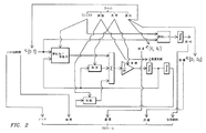
上述の最適化を計算し易くするために、図2に示され、上で検討された方程式に記載されたような列車の簡素化されたモデルが使用されることができる。最適なプロフィールに対する重要な改善が、熱的、電気的、および機械的制約が破られるかどうかをテストするために、生成された最適な動力シーケンスを用いるより詳細なモデルを引き出すことによって生成され、機関車または列車の機器を損傷することなしに達成されることができる、すなわち機関車に関する熱的および電気的制限ならびに列車間の力などのさらなる暗黙的な制約を満足することができる走行にもっと近い速度対距離を有する修正されたプロフィールをもたらす。 In order to facilitate the calculation of the above optimization, a simplified model of the train as shown in FIG. 2 and described in the equations discussed above can be used. Significant improvements to the optimal profile are generated by deriving a more detailed model using the generated optimal power sequence to test whether thermal, electrical, and mechanical constraints are violated, More to travel that can be achieved without damaging the locomotive or train equipment, i.e. it can satisfy further implicit constraints such as thermal and electrical restrictions on the locomotive and forces between trains Produces a modified profile with close speed versus distance.
再び図1を参照すると、運行が開始される(12)と、計画を発動するために動力命令が生成される(14)。本発明の実施形態の運転の設定に応じて、1つの命令は、最適な速度を達成するために機関車を最適化された動力命令に従わせる(16)。一実施形態は、列車の機関車のコンシストから実際の速度および動力の情報を取得する(18)。最適化のために使用されるモデルにおける共通の近似のおかげで、最適化された動力に対する修正の閉ループの計算が、所望の最適な速度を追跡するために取得される。列車の運転の制限のそのような修正は、自動的に、または列車の根本的な制御をいつも行っているオペレータによってなされることができる。 Referring again to FIG. 1, once the operation is started (12), a power command is generated to activate the plan (14). Depending on the driving settings of the embodiment of the present invention, one command causes the locomotive to follow an optimized power command to achieve optimal speed (16). One embodiment obtains actual speed and power information from the train locomotive consist of the train (18). Thanks to a common approximation in the models used for optimization, a modified closed-loop calculation for the optimized power is obtained to track the desired optimal speed. Such a modification of the train operating restrictions can be made automatically or by an operator who is always performing the fundamental control of the train.
いくつかの場合、最適化において使用されるモデルは実際の列車と大きく異なる可能性がある。これは、特別な貨物の追加または切り離し、経路内の故障した機関車、および初期データベース63内の誤りおよびオペレータによるデータ入力の誤りを含むがこれらに限定されない多くの理由で発生する可能性がある。これらの理由のために、監視システムはリアルタイムの列車のデータを使用してリアルタイムで機関車および/または列車のパラメータを推定する(20)。次に、推定パラメータが、運行が最初に作成されたときに仮定のパラメータと比較される(22)。仮定のパラメータと推定パラメータの任意の差に基づいて、運行が再計画されることができる(24)。概して、運行は、新しい計画をもとに著しい節約が実現されることができる場合に再計画される。
In some cases, the model used in the optimization can be very different from the actual train. This can occur for a number of reasons, including but not limited to the addition or removal of special cargo, failed locomotives in the route, and errors in the
運行が再計画される可能性があるその他の理由は、大域的な移動計画の目的に合致するための目的の変更の、指令などのリモートの場所からの命令および/またはオペレータの要求を含む。そのような大域的な移動計画の目的は、その他の列車のスケジュール、排気をトンネルから消散させるために必要な時間、保守作業などを含む可能性があるがこれらに限定されない。別の理由は、車内でのコンポーネントの故障が原因である可能性がある。再計画に関する方針は、以下でさらに詳細に検討されるように障害の重大性に応じて付加的な調整および大幅な調整にグループ化されることができる。概して、「新しい」計画は、上述の最適化問題の方程式(OP)に対する解から導出されなければならないが、本明細書において説明されるようにより速い近似解が発見されることができることが多い。 Other reasons that operations may be re-planned include command from a remote location such as a command and / or operator request for a change of purpose to meet the purpose of the global travel plan. The purpose of such a global travel plan may include, but is not limited to, other train schedules, time required to dissipate exhaust from the tunnel, maintenance operations, and the like. Another reason may be due to component failure in the car. Rescheduling policies can be grouped into additional adjustments and major adjustments depending on the severity of the failure as discussed in more detail below. In general, a “new” design must be derived from the solution to the optimization problem equation (OP) described above, but often a faster approximate solution can be found as described herein.
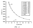
運転中、機関車42はシステム効率を継続的に監視し、更新が運行性能を向上することができるときにはいつでも実際の測定された効率に基づいて運行計画を継続的に更新する。再計画の計算は、(1つまたは複数の)機関車内で全て実行されることができるか、または無線技術が新しい計画を機関車42に伝達することができる指令または沿線の処理設備などのリモートの場所で全てもしくは部分的に実行されることができる。本発明の一実施形態は、効率伝達関数に関する機関車の一団のデータを作成するための効率の傾向を生成することもできる。機関車の一団全体のデータは、最初の運行計画を決定するときに使用されることができ、複数の列車の位置を考慮するときに鉄道網全体の最適化の折り合いをつけるために使用されることができる。例えば、図4に示される走行時間と燃料の使用のトレードオフ曲線は、特定の経路上の多くの同様の列車に関して収集されたアンサンブル平均をもとに更新された現時点の同じ経路上の列車の能力を反映する。したがって、多くの機関車から図4と同様の曲線を収集する中央指令機関は、列車の全体的な動きをよりうまく調整して燃料の使用またはスループットにおけるシステム全体の利益を達成するためにその情報を使用することができる。 During operation, the locomotive 42 continuously monitors system efficiency and continuously updates the operation plan based on actual measured efficiency whenever the update can improve operation performance. The re-plan calculation can be performed entirely within the locomotive (s), or remote such as command or along-line processing facilities where wireless technology can communicate the new plan to the locomotive 42. Can be executed in whole or in part. An embodiment of the present invention may also generate an efficiency trend for creating a locomotive fleet data for an efficiency transfer function. Locomotive fleet-wide data can be used when deciding on an initial travel plan, and used to make tradeoffs to optimize the entire rail network when considering the location of multiple trains be able to. For example, the trade-off curve of travel time and fuel use shown in FIG. 4 is for trains on the same current route updated based on ensemble averages collected for many similar trains on a particular route. Reflect abilities. Thus, a central command engine that collects curves similar to FIG. 4 from a number of locomotives will have that information in order to better coordinate the overall movement of the train to achieve overall system benefits in fuel usage or throughput. Can be used.
例えば列車が別の列車との計画された待ち合わせまたは追い越しに関して予定に遅れており、したがって遅れた時間を取り戻さなければならないとき、日常的な運転中の多くの事象が、同じ運行目的を維持する新しいまたは修正された運行計画を含む新しいまたは修正された計画の生成を動機付ける可能性がある。機関車の実際の速度、動力、および位置を使用して、計画された到着時間が現在推定(予測)される到着時間と比較される(25)。これらの時間の差と(ならびに指令またはオペレータによって検出または変更された)パラメータの差とに基づいて計画が調整される(26)。この調整は、計画からの逸脱を処理するための鉄道会社の方針に応じて自動的に行われることができるか、または車上のオペレータおよび指令が計画を戻すための最良のアプローチを連帯して決定するときに手動で行われることができる。計画が更新されるが、到着時間などであるがこれに限定されない当初の目的が同じままであるときにはいつでも、追加的変更、例えば当初の計画に復帰することの実現可能性に影響を与える可能性がある新しい将来の速度制限の変更が同時に考慮されることができる。そのような場合、元の運行計画が維持されることができない、または換言すると列車が元の運行計画の目的を達成することができない場合、本明細書において検討されるように(1つまたは複数の)その他の運行計画がオペレータ、リモートの設備、および/または指令に提示されることができる。 For example, when a train is behind schedule with respect to planned queuing or overtaking with another train, and therefore the delayed time must be regained, many events during routine operation are new to maintain the same operational objectives Or it may motivate the generation of a new or modified plan containing a modified travel plan. Using the actual speed, power, and position of the locomotive, the planned arrival time is compared to the currently estimated (predicted) arrival time (25). The plan is adjusted based on these time differences and the parameter differences (as well as detected or changed by commands or operators) (26). This adjustment can be made automatically according to the railway company policy for handling deviations from the plan, or together with the best approach for the operator and command on the vehicle to return the plan. Can be done manually when deciding. Any time the plan is updated but the original purpose remains the same, such as but not limited to arrival time, it may affect the feasibility of making additional changes, for example, returning to the original plan There are new future speed limit changes that can be considered simultaneously. In such cases, if the original operation plan cannot be maintained, or in other words, if the train cannot achieve the original operation plan's objectives, as discussed herein (one or more) Other travel plans can be presented to the operator, remote equipment, and / or command.
再計画は、当初の目的を変更することが望ましいときにもなされることができる。そのような再計画は、決まった予め計画されたときに行われることができるか、オペレータもしくは指令の裁量で手動で行われることができるか、またはそのような列車の運転の制限などの既定の制限が超えられるときに自動的に行われることができるかのいずれかである。例えば、現在の計画の実行が30分などの指定された閾値を超えるだけ遅れている場合、本発明の一実施形態は運行を再計画して、上述のようにより多くの燃料消費と引き換えに遅れに対処することができるか、またはできるとしたときに遅れた時間が取り戻されることができる程度(すなわち、残りの最小時間は何か、もしくは時間の制約内で節約されることができる最大の燃料)についてオペレータおよび指令に知らせることができる。再計画に関するその他の誘因は、消費燃料、あるいは到着時間、機器の故障および/もしくは機器の一時的な不調(過度に高い温度、もしくは過度に低い温度での運転など)による馬力の損失、ならびに/または想定された列車の荷重におけるような全体の設定の誤りの検出を含むがこれらに限定されない動力コンシストの調子に基づいて想定されることもできる。すなわち、変化が現在の運行に関する機関車の性能の低下を反映する場合、これらは、最適化プロセスに使用されるモデルおよび/または方程式に盛り込まれることができる。 Rescheduling can also be done when it is desirable to change the original objective. Such re-planning can be done at a fixed pre-planned time, can be done manually at the discretion of the operator or command, or predefined such as restrictions on train operation Either can be done automatically when the limit is exceeded. For example, if execution of the current plan is delayed by more than a specified threshold, such as 30 minutes, one embodiment of the present invention replans the operation and delays in exchange for more fuel consumption as described above. To the extent that the delayed time can be recaptured when it is possible (ie what is the minimum remaining time or the maximum fuel that can be saved within time constraints) ) Can be informed to the operator and command. Other incentives for rescheduling include fuel consumption or loss of horsepower due to time of arrival, equipment failure and / or temporary malfunction of equipment (such as operation at excessively high or excessively low temperatures), and / or Or it can be envisaged based on the power consistency tone, including but not limited to detection of global setting errors such as in assumed train loads. That is, if the changes reflect a decrease in locomotive performance with respect to current operation, these can be incorporated into the models and / or equations used in the optimization process.
計画の目的の変更は、1つの列車に関する計画が別の列車の能力を損なう事象を調整して目的を達成する必要性から生じる可能性もあり、異なるレベル、例えば指令オフィスでの調整が必要とされる。例えば、待ち合わせおよび追い越しの調整が、列車同士の通信を通じてさらに最適化されることができる。したがって、例として、オペレータがそのオペレータが待ち合わせおよび/または追い越しのための場所への到着がスケジュールよりも遅れていることを知っている場合、もう一方の列車からの通信が遅れている列車のオペレータ(および/または指令)に助言することができる。オペレータは、列車の運行計画を再計算するために予測される遅れた到着に関する情報を入力することができる。一実施形態において、本発明は、万一スケジューリングされた待ち合わせおよび/または追い越し時間の制約が満たされない可能性がありそうな場合にどの列車が速度を落とすべきか、または速度を上げるべきかを指令が決定することを可能にするために高レベルまたは鉄道網レベルで使用される。本明細書において検討されるように、これは、各列車がその列車の計画の目的をどのように変更すべきかを優先順位付けするために列車がデータを指令に送信することによって遂行される。選択は、状況に応じてスケジュールまたは燃料の節約の利点のいずれかに基づいてなされることができる。 A change in the purpose of a plan can arise from the need to adjust the event that a plan for one train impairs the capabilities of another train to achieve the goal, and requires adjustment at a different level, for example the command office Is done. For example, queuing and overtaking adjustments can be further optimized through communication between trains. Thus, as an example, if an operator knows that the operator is arriving at a place for meeting and / or overtaking is behind schedule, the operator of the train that is delayed from the other train (And / or directive) can be advised. The operator can enter information regarding anticipated late arrivals to recalculate the train operation plan. In one embodiment, the present invention directs which train should slow down or speed up in the unlikely event that scheduled queuing and / or overtaking time constraints may not be met. Used at the high level or rail network level to allow to be determined. As discussed herein, this is accomplished by the train sending data to the command to prioritize how each train should change its train planning objective. Selection can be made based on either a schedule or fuel saving benefits depending on the situation.
手動または自動で開始された再計画のいずれに関しても、本発明の実施形態は、2つ以上の運行計画をオペレータに提示することができる。例示的実施形態において、本発明はオペレータに異なるプロフィールを提示し、オペレータが到着時間を選択し、さらに対応する燃料および/または排気の影響を理解することを可能にする。そのような情報は、同様の検討のために指令に単なる選択肢のリストとしてか、または図4に示されたような複数のトレードオフ曲線としてかのいずれかで提供されることもできる。 With respect to either manual or automatic initiated replanning, embodiments of the present invention can present more than one travel plan to the operator. In an exemplary embodiment, the present invention presents different profiles to the operator, allowing the operator to select an arrival time and further understand the corresponding fuel and / or exhaust effects. Such information can be provided either simply as a list of options to the directive for similar considerations, or as a plurality of trade-off curves as shown in FIG.
一実施形態において、本発明は、現在の計画におよび/または将来の計画のためにのいずれかで組み込まれることができる列車および動力コンシストの重要な変更を学習し、それらの重要な変更に適合する能力を含む。例えば、上で検討された誘因のうちの1つは馬力の損失である。馬力の損失の後か、運行を開始するときのいずれかに時間の経過と共に馬力を上げるとき、いつ所望の馬力が達成されるのかを決定するために遷移ロジックが利用される。この情報は、万一馬力の損失が後で再び起こった場合に将来の運行かまたは現在の運行のいずれかを最適化するのに使用するために機関車のデータベース61に保存されることができる。 In one embodiment, the present invention learns and adapts to important changes in trains and power consistency that can be incorporated either into the current plan and / or for future plans. Including the ability to For example, one of the incentives discussed above is a loss of horsepower. Transition logic is used to determine when the desired horsepower is achieved when increasing horsepower over time, either after a loss of horsepower or when starting operation. This information can be stored in the locomotive database 61 for use in optimizing either future operations or current operations should a horsepower loss occur again later. .
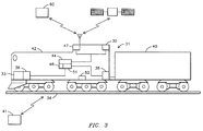
図3は本発明の要素の例示的実施形態を示す。ロケータ要素30は列車31の位置を判定する。ロケータ要素30は、列車31の位置を判定するGPSセンサ、またはセンサシステムを含む。そのようなその他のシステムの例は、無線周波数積載物自動認識(RF AEI)タグなどの沿線のデバイス、指令、および/または映像に基づく判定を含むことができるがこれらに限定されない。別のシステムは、機関車に搭載された(1つまたは複数の)タコメータ、および基準点からの距離計算を使用することができる。既に検討されたように、無線通信システム47が、列車間の、および/または指令などのリモートの場所との通信を可能にするために提供されることもできる。走行場所についての情報がその他の列車から通信システムを介して転送されることもできる。
FIG. 3 shows an exemplary embodiment of the elements of the present invention. The
軌道特徴付け要素33は軌道についての情報、主として勾配および高度および曲率の情報を提供する。軌道特徴付け要素33は、車載の軌道完全性データベース36を含むことができる。センサ38は、機関車のコンシスト42によって加えられる牽引力40、機関車のコンシスト42のスロットの設定、機関車のコンシスト42の構成情報、機関車のコンシスト42の速度、個々の機関車の構成情報、個々の機関車の能力などを測定する。例示的実施形態において、機関車のコンシスト42の構成情報はセンサ38を使用せずに取り込まれることができるが、上で検討されたようにその他のアプローチによって入力される。さらに、コンシスト内の機関車の調子が考慮されることもできる。例えば、コンシスト内の1両の機関車が動力ノッチレベル5を超えて運転することができない場合、この情報は運行計画を最適化するときに使用される。
The
ロケータ要素からの情報は、列車31の適切な到着時間を決定するために使用されることもできる。例えば、軌道34に沿って目的地に向かって移動している列車31があり、その列車31の後ろに続く列車がなく、当該列車が満足すべき決まった到着期限を持たない場合、無線周波数積載物自動認識(RF AEI)タグ、指令、および/または映像ベース判定を含むがこれらに限定されないロケータ要素が、列車31の正確な位置を判定するために使用されることができる。さらに、これらの信号システムからの入力が、列車の速度を調整するために使用されることができる。以下で検討される車載の軌道データベースと、GPSなどのロケータ要素とを使用して、本発明の一実施形態は、所与の機関車の位置における信号システムの状態を反映するためにオペレータのインターフェースを調整する。信号の状態が前もって制限速度を示す状況において、プランナは、燃料消費を節約するために列車を減速させることを選択することができる。
Information from the locator element can also be used to determine the appropriate arrival time of the
ロケータ要素30からの情報は、計画の目的を目的地への距離の関数として変更するために使用されることもできる。例えば、経路に沿った混雑についての避けがたい不確実性のために、経路の初めの方の部分における「より速い」時間の目的が、統計的に後で発生する遅延に対する防護措置として使用されることができる。特定の運行に関してそのような遅延が発生しない場合、行程の後の方の部分における目的は、前に蓄えられた組み込まれた余分な時間を利用し、それによっていくらかの燃料効率を回復するために修正されることができる。同様の方針が、排気制限の目的、例えば都市部に接近するときに適用される排気の制約に関して実施されることができる。
Information from the
防護方針の一例として、運行がニューヨークからシカゴまで計画される場合、システムは、運行の初めか、運行の中間か、または運行の終わりのいずれかにおいて列車を遅く運転するオプションを提供することができる。本発明の一実施形態は、天候条件、軌道の保守などであるがこれらに限定されない未知の制約が運行中に発生し、明らかになる可能性があるので運行の終わりにより遅い運転を可能にするように運行計画を最適化する。別の考えとして、以前から混雑している地域が知られている場合、計画は、そのような地域の周辺での運転の柔軟性を増加させるためのオプションを用いて作成される。したがって、本発明の実施形態は、時間/距離の関数としての重み付け/ペナルティを課すことを将来の考慮に入れることもでき、および/または知られている/過去の経験に基づいて考慮することもできる。当業者は、天候条件、軌道の条件、軌道上のその他の列車などを考慮に入れるためのそのような計画および再計画が運行中いつでも考慮に入れられることができ、運行計画がそれに従って調整されることを容易に認識するであろう。 As an example of a protection policy, if the operation is planned from New York to Chicago, the system can provide an option to drive the train late, either at the beginning of the operation, in the middle of the operation, or at the end of the operation . One embodiment of the present invention allows for slower driving at the end of service as unknown constraints such as but not limited to weather conditions, track maintenance, etc. may occur and become apparent during service. To optimize the operation plan. Another idea is that if a previously congested area is known, the plan is created with options to increase driving flexibility around such areas. Thus, embodiments of the present invention may take into account future weighting / penalties as a function of time / distance and / or may be based on known / past experience. it can. Those skilled in the art can take into account such plans and re-plans to take into account weather conditions, track conditions, other trains on the track, etc. at any time during operation, and the operation plan is adjusted accordingly. You will easily recognize that.
図3は、本発明の実施形態の一部であることができるその他の要素をさらに開示する。プロセッサ44は、ロケータ要素30、軌道特徴付け要素33、およびセンサ38から情報を受信するように動作する。アルゴリズム46がプロセッサ44内で動作する。アルゴリズム46は、本明細書において説明されるように機関車42、列車31、軌道34、およびミッションの目的を含むパラメータに基づいて最適化された運行計画を計算する。例示的実施形態において、運行計画は、アルゴリズムに提供されている簡素化の仮定を用いて適用可能な物理的過程から導出された非線形微分方程式の解として、列車31が軌道34に沿って移動するときの列車の振る舞いに関するモデルに基づいて確立される。アルゴリズム46は、ロケータ要素30、軌道特徴付け要素33、および/またはセンサ38からの情報にアクセスして、機関車のコンシスト42の燃料消費を最小化し、機関車のコンシスト42の排気を最小化し、所望の運行時間を定め、および/または機関車のコンシスト42上での適切な乗務員の稼働時間を保証する運行計画を生成する。例示的実施形態において、運転士、またはコントローラ要素51も提供される。本明細書において検討されるように、コントローラ要素51は、列車が運行計画に従うときに列車を制御することができる。本明細書でさらに検討される例示的実施形態において、コントローラ要素51は、自律的に列車運転の判断を行う。別の例示的実施形態において、オペレータは、そのオペレータの裁量で列車に運行計画に従うように、または運行計画から逸脱するように指示することに関与する可能性がある。
FIG. 3 further discloses other elements that may be part of an embodiment of the present invention. The
本発明の一実施形態において、運行計画は、当該計画が実行されているときにリアルタイムで修正可能である。これは、計画最適化アルゴリズムの複雑性のために、長距離の運行のための最初の計画を生成することを含む。運行プロフィールの全長が所与の距離を超えるとき、アルゴリズム46が、ミッションを中間地点に分割することによってミッションを分割するために使用されることができる。単一のアルゴリズム46のみが検討されるが、当業者は、2つ以上のアルゴリズムが使用されることができることと、そのような複数のアルゴリズムが運行計画を生成するために結びつけられることとを容易に認識するであろう。
In one embodiment of the present invention, the operation plan can be modified in real time when the plan is being executed. This involves generating an initial plan for long-distance travel due to the complexity of the plan optimization algorithm. When the total length of the flight profile exceeds a given distance, the
運行の中間地点は、対向する交通との待ち合わせのための、もしくは現在の列車の後ろの列車による追い越しのための単線の側線、操車場の側線、車両が追加および切り離しされる引込線、ならびに計画された保守作業の場所などであるがこれらに限定されない列車31が停車する理に適った場所を含むことができる。そのような中間地点において、列車31は、スケジューリングされた時間にその場所にいるか、停車されているか、または指定範囲内の速度で移動しているように要求されることができる。中間地点における到着から出発までの期間は停車時間と呼ばれる。
The intermediate point of operation is a single line for meeting with opposite traffic or for passing by the train behind the current train, a side line for the yard, a service line where vehicles are added and disconnected, and planned. However, it is possible to include a place suitable for the reason that the
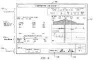
例示的実施形態において、本発明は、長い運行を体系的なプロセスに従ってより小さなセグメントに分けることができる。各セグメントは、長さが幾分任意的であることができるが、概して、停車もしくは著しい速度制限などの理に適った場所において、またはその他の経路との合流点を規定する重要な中間地点もしくは距離標において選択される。このようにして選択された部分またはセグメントが与えられると、運転プロフィールが、図4に示されたような独立変数とみなされる走行時間の関数として軌道の各セグメントに対して生成される。各セグメントに関連する使用燃料/走行時間のトレードオフが、列車31が軌道のそのセグメントに到達する前に計算されることができる。したがって、全体的な運行計画が、各セグメントに対して生成された運転プロフィールから生成されることができる。本発明の一実施形態は、必要とされる総運行時間が満足され、全てのセグメントに渡る総消費燃料が最小化されるように運行の全てのセグメントに走行時間を最適に分散する。例示的な3つのセグメントの運行が図6に開示され、以下で検討される。しかし、当業者は、複数のセグメントが検討されるが、運行計画が完全な運行を表す単一のセグメントから成ることができることを認識するであろう。
In an exemplary embodiment, the present invention can divide long trips into smaller segments according to a systematic process. Each segment can be somewhat arbitrary in length, but in general, at a reasonable location such as a stop or a significant speed limit, or an important waypoint that defines a junction with other routes or Selected in the distance marker. Given a portion or segment thus selected, a driving profile is generated for each segment of the track as a function of travel time, which is considered an independent variable as shown in FIG. The fuel / travel time tradeoff associated with each segment can be calculated before the
図4は、燃料使用/走行時間曲線の例示的実施形態を示す。上述のように、そのような曲線50は、各セグメントに対して様々な走行時間に関する最適な運行プロフィールを計算するときに生成される。すなわち、所与の走行時間51に対して、使用燃料52は、上述のように計算された詳細な運転プロフィールの結果である。各セグメントに対する走行時間が割り当てられると、動力/速度計画が、既に計算された解から各セグメントに対して決定される。速度制限の変更などであるがこれに限定されないセグメント間の任意の中間地点の速度の制約が存在する場合、それらは最適な運行プロフィールの生成中に調和させられる。速度の制約が単一のセグメント内でのみ変わる場合、燃料使用/走行時間曲線50は、変更されるセグメントのみに対して再計算される必要がある。このプロセスは、運行のより多くの部分またはセグメントを再計算するために必要とされる時間を削減する。機関車のコンシストまたは列車が経路に沿って大きく変わる(例えば機関車を失うこと、または鉄道車両の追加もしくは切り離し)場合、全ての後続のセグメントに対する運転プロフィールは再計算され、曲線50の新しい場合を生成しなければならない。そのとき、これらの新しい曲線50は、残りの運行を計画するための新しいスケジュールの目的と共に使用される。
FIG. 4 shows an exemplary embodiment of a fuel usage / runtime curve. As described above, such a
運行計画が上で検討されたように生成されると、速度および動力対距離の曲線が、列車が要求される運行時間で最小の燃料および/または排気で目的地に到着することを可能にする。運行計画を実行するためのいくつかの技術が存在する。以下により詳細に提供されるように、指導モードの1つの例示的実施形態において、本発明はオペレータに制御情報を表示する。オペレータは当該情報に従って、最適な運行計画により決定されたように要求される動力および速度を達成する。したがって、このモードにおいて、オペレータは列車の運転に使用するための運転の提案を提供される。別の例示的実施形態において、列車を加速するための、または一定速度を維持するための制御動作が本発明によって実行される。しかし、列車31が減速されなければならないとき、オペレータはブレーキシステム52を制御することによってブレーキをかける責任を負う。別の例示的実施形態において、本発明は、所望の速度−距離の経路に従うために必要とされるように動力および制動動作を命じる。
When an operation plan is generated as discussed above, speed and power versus distance curves allow the train to arrive at the destination with minimal fuel and / or emissions at the required operation time. . There are several techniques for executing the operation plan. As provided in more detail below, in one exemplary embodiment of the teaching mode, the present invention displays control information to the operator. According to the information, the operator achieves the required power and speed as determined by the optimal operation plan. Thus, in this mode, the operator is provided with driving suggestions for use in driving the train. In another exemplary embodiment, control operations for accelerating the train or maintaining a constant speed are performed by the present invention. However, when the
変動する向かい風および/または追い風によって引き起こされる列車の荷重の変動などであるがこれに限定されない事象を説明するためにプロフィール内の動力制御シーケンスを修正するためにフィードバック制御方針が使用される。別のそのような誤差は、最適化された運行計画における想定と比較されたときの列車の質量および/または抵抗などであるがこれらに限定されない列車のパラメータの誤差によって引き起こされる可能性がある。第3の種類の誤差は、軌道データベース36内の不正確な情報によって起こる可能性がある。別の起こりうる誤差は、機関車のエンジン、主電動機のサーマルディレーション(thermal deration)、および/またはその他の要素によるモデリングされていない性能の差異を含む可能性がある。フィードバック制御方針は、位置の関数としての実際の速度を所望の最適なプロフィールの速度と比較する。この差に基づいて、最適な動力プロフィールに対する修正が、実際の速度を最適なプロフィールに近付けるために加えられる。安定した統制を保証するために、閉ループの性能安定性を保証するためにフィードバック速度をフィルタリングして動力の修正にする補償アルゴリズムが提供されることができる。補償は、性能目標を達成するために制御システム設計の分野に精通した者によって使用される標準的な動的補償を含むことができる。
A feedback control strategy is used to modify the power control sequence in the profile to account for events such as, but not limited to, train load fluctuations caused by fluctuating headwinds and / or tailwinds. Another such error may be caused by errors in train parameters such as, but not limited to, train mass and / or resistance as compared to assumptions in an optimized travel plan. A third type of error can be caused by inaccurate information in the
種々の態様によって、本発明は、鉄道の運転における例外ではなく規則である、運行の目的の変更に対処するための最も単純な、ひいては最も高速な手段を可能にする。経路に沿って停車場が存在する地点Aから地点Bへの燃料が最適な運行を決定するための、およびいったん運行が始まったときに運行の残りの部分のために運行を更新するための例示的実施形態において、準最適な分解方法が最適な運行プロフィールを発見するために使用されることができる。モデリング方法を使用して、計算方法は、停車場があるときに全ての速度制限および機関車の能力の制約を満たすために特定の走行時間ならびに初期および最終速度を有する運行計画を発見することができる。以下の検討は燃料の使用を最適化することを対象とするが、以下の検討は、排気、スケジュール、乗務員の快適さ、および荷重の影響などであるがこれらに限定されないその他の要素を最適化するために適用されることもできる。方法は、最初に運行計画を作成することに使用されることができ、より重要なことに、運行を開始した後で目的の変更に適合することに使用されることができる。 By various aspects, the present invention allows for the simplest and thus the fastest means to deal with changes in the purpose of operation, which is a rule, not an exception in railway operation. Exemplary for determining the optimal operation of fuel from point A to point B where a stop exists along the route and for updating the operation for the remainder of the operation once it has begun In an embodiment, a sub-optimal decomposition method can be used to find the optimal travel profile. Using modeling methods, the calculation method can find an operation plan with specific travel times and initial and final speeds to meet all speed limits and locomotive capacity constraints when there is a stop . The following considerations will focus on optimizing fuel use, but the following considerations will optimize other factors such as but not limited to emissions, schedules, crew comfort, and load effects It can also be applied to The method can be used to initially create a travel plan, and more importantly, it can be used to adapt to a change of interest after the start of travel.
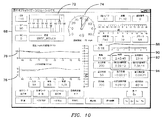
本明細書において検討されるように、本発明の一実施形態は、図5に示される例示的なフローチャートに示されるような、および図6に詳細に示される例示的3セグメントの例のような設定を使用する。示されるように、運行は、2つ以上のセグメントT1、T2、およびT3に分けられることができる。しかし、本明細書において検討されるように、運行を単一のセグメントとみなすことが可能である。本明細書において検討されるように、セグメントの境界は等しい長さのセグメントをもたらさない可能性がある。その代わりに、セグメントはふさわしいまたはミッションに固有の境界を使用する。最適な運行計画が各セグメントに対して予め計算される。燃料の使用対運行時間が満たされるべき運行の目的である場合、燃料対運行時間曲線が各セグメントに対して生成される。本明細書において検討されるように、曲線はその他の要素に基づくことができ、それらの要素は運行計画を用いて満たされるべき目的である。運行時間が決定されているパラメータであるとき、全体的な運行時間の制約を満たしながら各セグメントに対する運行時間が計算される。 As discussed herein, one embodiment of the present invention is as shown in the exemplary flow chart shown in FIG. 5 and in the exemplary three segment example shown in detail in FIG. Use settings. As shown, the journey can be divided into two or more segments T1, T2, and T3. However, as discussed herein, a run can be considered a single segment. As discussed herein, segment boundaries may not result in segments of equal length. Instead, the segment uses appropriate or mission-specific boundaries. An optimal operation plan is pre-calculated for each segment. If the fuel usage versus operating time is the purpose of the operation to be met, a fuel versus operating time curve is generated for each segment. As discussed herein, the curve can be based on other factors, which are the objectives to be met using the travel plan. When the operating time is a determined parameter, the operating time for each segment is calculated while satisfying the overall operating time constraint.
図6は、例示的3セグメントの200マイルの運行に対する速度制限97を示す。さらに示されているのは、200マイルの運行に渡る勾配の変化98である。走行時間に渡って運行の各セグメントに対する使用された燃料の曲線を示す組み合わされたグラフ99も示される。
FIG. 6 shows a
上述の最適な制御の設定を使用して、この計算方法は、停車場があるときに全ての速度制限および機関車の能力の制約を満たすために特定の走行時間ならびに初期および最終速度を有する運行計画を発見することができる。以下の詳細な検討は燃料の使用を最適化することを対象とするが、以下の詳細な検討は、排気などであるがこれに限定されない、本明細書において検討されるその他の要素を最適化するために適用されることもできる。本方法は、停車場での所望の停車時間に対応することができ、例えば、側線に入る、または側線を通過するための時間が重要である単線の運転において必要とされ得る場所への最も早い到着および場所からの最も早い出発に関する制約を考慮する。 Using the optimal control settings described above, this calculation method can be used for an operation plan with specific travel times and initial and final speeds to meet all speed limits and locomotive capacity constraints when there is a stop. Can be found. The following detailed discussion is aimed at optimizing fuel use, but the following detailed discussion optimizes other factors discussed herein, such as but not limited to emissions. It can also be applied to The method can correspond to the desired stop time at the stop, for example the earliest arrival at a location that may be required in single-line driving where time to enter or pass the side line is important And consider the constraints on the earliest departure from the place.
一実施形態によれば、本発明は時間T内に走行される距離D0からDMまでの燃料が最適な運行を発見し、ここでM−1個の中間の停車場がD1,...,DM−1にあり、これらの停車場の到着および出発時間が以下の式によって制約される。 According to one embodiment, the present invention discovered fuel optimal trip from distance D 0 is running within the time T to D M, where M-1 pieces of the intermediate depot is D 1,. . . , D M−1 and the arrival and departure times of these stops are constrained by the following equation:
![]()
![]()
![]()
![]()
![]()
![]()
![]()
![]()
![]()
![]()
![]()
![]()
いったん運行が実施中になると、問題は、運行が進むが、しかし燃料が最適な解に従うことを変動が妨げるときに、(元は時間T内のD0からDMまでの)運行の残りの部分に関する燃料が最適な解を再決定することである。現在の距離および速度をそれぞれxおよびvとし、ここで Once the operation is being performed, the problem, but operation proceeds, but when the fuel prevents variation to follow the optimal solution, the (original from D 0 in time T to D M) remaining in operation The fuel for the part is to redetermine the optimal solution. Let the current distance and speed be x and v, respectively, where
![]()
![]()
![]()
![]()
![]()
![]()
上で検討されたように、より効率的な再計画を可能にする例示的なプロセスは、分割されたセグメントから停車場間の運行に関する最適な解を構築する。走行時間TiのDi−1からDiまでの運行に関して、1組の中間点 As discussed above, an exemplary process that allows for more efficient replanning builds an optimal solution for travel between split segments and stops. A set of midpoints for the travel time T i from D i-1 to D i
![]()
![]()
![]()
![]()
![]()
![]()
![]()
![]()
![]()
![]()
![]()
![]()
上記式は、関数Fi(t)が、初めに関数 In the above equation, the function F i (t)
![]()
![]()
![]()
![]()
![]()
![]()
上述の分割に基づいて、上述のアプローチよりもより簡素な準最適再計画アプローチは、再計画を列車が距離の地点 Based on the partitioning described above, the suboptimal replanning approach, which is simpler than the approach described above, re-plans the train at the point of distance.
![]()
![]()
![]()
![]()
![]()
![]()
距離の地点Diが到達されるまで Until distance point Di is reached
![]()
![]()
![]()
![]()
![]()
![]()
上で開示された閉ループの構成に関して、地点Aから地点Bまで列車31を動かすために必要とされる総入力エネルギーは、4つの構成要素、具体的には、地点Aと地点Bの間の運動エネルギーの差と、地点Aと地点Bの間の位置エネルギーの差と、摩擦およびその他の抵抗損失によるエネルギー損失と、ブレーキをかけることによって消散するエネルギーとの合計によって構成される。開始および終了速度が同じ(例えば、静止)であると仮定すると第1の構成要素は0である。さらに、第2の構成要素は運転方針とは無関係である。したがって、後の2つの構成要素の合計を最小化すれば十分である。
For the closed loop configuration disclosed above, the total input energy required to move the
一定の速度プロフィールに従うことは抵抗損失を最小化する。また、一定の速度プロフィールに従うことは、一定速度を保つために制動が必要とされないときは総エネルギー入力を最小化する。しかし、一定速度を保つために制動が必要とされる場合、単に一定速度を保つために制動をかけることは、大抵、ブレーキによって消散されたエネルギーを補充する必要があるので総必要エネルギーを増加させる。速度の変動を減らすことによって、制動によって生じる抵抗損失の結果的な減少によるオフセットよりも追加的なブレーキ損失が大きい場合に何らかの制動が実際に総エネルギー使用を減少させる可能性があり得る。 Following a constant speed profile minimizes resistive losses. Also, following a constant speed profile minimizes the total energy input when braking is not required to maintain a constant speed. However, if braking is required to maintain a constant speed, simply applying the brake to maintain a constant speed usually increases the total energy requirement as it is necessary to replenish the energy dissipated by the brake. . By reducing the speed variation, it is possible that some braking will actually reduce the total energy usage if the additional braking loss is greater than the offset due to the resulting decrease in resistance loss caused by braking.
上述の事象の収集から再計画を完了した後で、新しい最適なノッチ/速度計画は、本明細書において説明される閉ループ制御を使用して守られることができる。しかし、場合によっては、上述のセグメント分解計画を実行する十分な時間がない可能性があり、特に、尊重されなければならない重要な速度制限が存在するときは別のやり方が好まれ得る。本発明の態様は、「スマートクルーズ制御」と呼ばれるアルゴリズムを用いてこれを遂行する。スマートクルーズ制御アルゴリズムは、既知の地形上で列車31を運転するためのエネルギー効率の良い(したがって、燃料効率の良い)準最適な指示を運行中に生成するための効率的なプロセスである。このアルゴリズムは、常に軌道34に沿った列車31の位置の知識と、軌道の勾配および曲率対位置の知識とを仮定する。方法は列車31の運動に関する質点モデルを利用し、この質点モデルのパラメータは、上述の列車の運動のオンライン計測から適応的に推定されることができる。
After completing the re-planning from the above event collection, the new optimal notch / velocity plan can be guarded using the closed loop control described herein. However, in some cases, there may not be enough time to perform the segment decomposition scheme described above, and another approach may be preferred, especially when there are significant speed limits that must be respected. An aspect of the present invention accomplishes this using an algorithm called “smart cruise control”. The smart cruise control algorithm is an efficient process for generating energy efficient (and thus fuel efficient) sub-optimal instructions for driving
スマートクルーズ制御アルゴリズムは、3つの主な構成要素、具体的には、速度制限の引き下げのエネルギー効率の良いガイドとして働く修正された速度制限プロフィールと、速度の変動の最小化と制動のバランスを取るように試みる理想的スロットルまたはダイナミックブレーキ設定プロフィールと、実際のパラメータと比較されるときのモデルリングされたパラメータの不一致を補償するための速度フィードバックループを使用する、後の2つの構成要素を組み合わせてノッチ命令を生成するためのメカニズムとを有する。スマートクルーズ制御は、アクティブ制動を行わない(すなわち、運転士が信号を送られ、必要な制動を行うと想定される)本発明の実施形態、またはアクティブ制動を行う変形形態において指針に対処することができる。 The smart cruise control algorithm balances the three main components, specifically a modified speed limit profile that serves as an energy efficient guide to lowering the speed limit, and minimizing speed variation and braking Combine the latter two components using an ideal throttle or dynamic brake setting profile to try and a speed feedback loop to compensate for the modeled parameter mismatch when compared to actual parameters And a mechanism for generating notch instructions. Smart cruise control does not perform active braking (i.e., it is assumed that the driver is signaled and performs the required braking), addressing the pointer in an embodiment of the present invention, or a variant that performs active braking Can do.
ダイナミックブレーキを制御しないクルーズ制御アルゴリズムに関して、3つの例示的な構成要素は、速度制限の削減のエネルギー効率の良いガイドとして働く修正された速度制限プロフィール、オペレータにいつ制動がかけられるべきであるかを知らせるための通知信号、速度の変動を最小化することとオペレータにブレーキをかけるように通知することとの間のバランスを取るように試みる理想的なスロットルプロフィール、および実際のパラメータに対するモデルパラメータの不一致を補償するためのフィードバックループを使用するメカニズムである。 For cruise control algorithms that do not control dynamic braking, three exemplary components include a modified speed limit profile that serves as an energy efficient guide to speed limit reduction, when an operator should be braked Notification signal to inform, ideal throttle profile trying to balance between minimizing speed variation and notifying the operator to brake, and model parameter mismatch to actual parameters It is a mechanism that uses a feedback loop to compensate.
本発明の態様によれば、さらに含まれるのは、列車31の重要なパラメータ値を特定するためのアプローチである。例えば、列車の質量を推定することに関して、時間の経過と共に生じる可能性がある誤差を検出するためにカルマンフィルタおよび逐次最小自乗アプローチが利用されることができる。
Further included according to aspects of the present invention are approaches for identifying important parameter values for
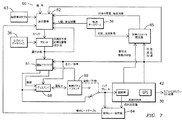
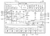
図7は、本発明の例示的なフローチャートを示す。既に検討されたように、指令センタ60などのリモートの設備が本発明よる使用のための情報を提供することができる。示されるように、そのような情報は実行制御要素62に提供される。さらに実行制御要素62に供給されるのは、機関車モデリング情報データベース63、軌道の勾配情報および速度制限情報などであるがこれらに限定されない軌道情報データベース36、列車の重量および抵抗係数などであるがこれらに限定されない推定された列車のパラメータ、ならびに燃料レート推定器64からの燃料レートテーブルである。実行制御要素62は、図1により詳細に開示されたプランナ12に情報を供給する。運行計画が計算されてしまうと、計画は、運転アドバイザ、運転士、またはコントローラ要素51に供給される。運行計画は、実行制御要素62がその他の新しいデータが提供されたときに運行を比較することができるように実行制御要素62にも供給される。
FIG. 7 shows an exemplary flowchart of the present invention. As already discussed, a remote facility such as
上で検討されたように、運転アドバイザ51はノッチ動力を予め決められたノッチ設定または最適な連続的ノッチ動力値のいずれかに自動的に設定することができる。速度命令を機関車31に供給することに加えて、オペレータがプランナが推奨した内容を見ることができるようにディスプレイ68が提供される。オペレータは制御盤69も利用できる。制御盤69を通じて、オペレータは、推奨されたノッチ動力を適用するかどうかを判断することができる。この目的のために、オペレータは、目的のまたは推奨の動力を制限することができる。すなわち、いつでも、オペレータは、運行計画が列車31を減速することを推奨する場合にブレーキをかけるかどうかを含む機関車のコンシストの運転に関する動力設定について最終的な権限を常に有する。例えば、暗い地域内を運転する場合、または沿線の機器からの情報が情報を列車に電子的に送信することができず、代わりにオペレータが沿線の機器からの視覚的な信号を見る場合、オペレータは、軌道データベースに含まれる情報、および沿線の機器からの視覚的な信号に基づいて命令を入力する。列車31がどのように機能しているかに基づいて、燃料の測定に関する情報が燃料レート推定器64に供給される。概して燃料流量の直接測定は機関車のコンシストにおいては利用できないので、運行のある地点までの消費燃料に関する全ての情報、および最適な計画が守られる場合の将来の予測は、最適な計画の作成に使用されたモデルなどの較正された物理的過程のモデルを使用する。例えば、そのような予測は、使用された累積の燃料を導出するための測定された総馬力と知られている燃料の特性との使用を含むことができるがこれに限定されない。
As discussed above, the driving
列車31は、上で検討されたようにGPSセンサなどのロケータデバイス30も有する。情報が列車パラメータ推定器65に供給される。そのような情報は、GPSセンサのデータ、牽引力/制動力データ、制動状態データ、速度、および速度データの任意の変化を含むことができるがこれらに限定されない。勾配に関する情報および速度制限の情報と共に、列車の重量および抵抗係数の情報が実行制御要素62に供給される。
本発明の一実施形態は、最適化の計画および閉ループ制御の実行の全体を通じて、連続的に変更可能な動力の使用を可能にすることもできる。従来の機関車において、概して動力は8つの離散的なレベルに量子化される。現在の機関車は、上述の最適化方法に組み込まれることができる馬力の連続的な変化を実現することができる。連続的な動力を用いて、機関車42は、例えば副次的負荷および動力伝送損失を最小化すること、ならびに最適な効率のエンジン馬力の領域を微調整することによって、または排気の余裕が増加する点まで運転条件をさらに最適化することができる。例は、冷却システムの損失を最小化すること、交流発電機の電圧を調整すること、エンジン回転数を調整すること、および駆動軸の数を減らすことを含むがこれらに限定されない。さらに、機関車42は、車載の軌道データベース36と予測された性能要件とを使用して、目的の燃料消費/排気のために最適な効率を提供するために副次的負荷および動力伝送損失を最小化することができる。例は、平らな地形上でいくつかの駆動軸を削減すること、およびトンネルに進入する前に機関車のエンジンを予め冷却することを含むがこれらに限定されない。
One embodiment of the present invention may also allow the use of continuously variable power throughout the optimization planning and execution of closed loop control. In conventional locomotives, power is typically quantized to eight discrete levels. Current locomotives can achieve a continuous change in horsepower that can be incorporated into the optimization method described above. With continuous power, the locomotive 42 can increase exhaust margins, for example, by minimizing secondary loads and power transmission losses, and by fine-tuning the area of engine horsepower for optimal efficiency. It is possible to further optimize the operating conditions up to the point to do. Examples include, but are not limited to, minimizing cooling system losses, adjusting alternator voltage, adjusting engine speed, and reducing the number of drive shafts. In addition, the locomotive 42 uses the on-
本発明の一実施形態は、車載の軌道データベース36と予測された性能とを使用して、列車が坂および/またはトンネルに近付くときにその列車が十分な速度を有することを保証するなど、機関車の性能を調整することもできる。例えば、これは、方程式(OP)を解く生成された最適計画生成の一部になる、特定の位置における速度の制約として表されることができる。さらに、実施形態は、牽引力ランプレート(ramp rates)および最大制動力ランプレートなどであるがこれらに限定されない列車操作規則を組み込むことができる。これらは、最適な運行プロフィールに関する定式化に直接組み込まれることができるか、または代替的に、動力の適用を制御して目的の速度を達成するために使用される閉ループレギュレータに組み込まれることができる。
One embodiment of the present invention uses an in-
好ましい実施形態において、本発明は列車のコンシストの本務機関車にのみ搭載される。たとえ特定の態様によって本発明がデータ、またはその他の機関車とのインタラクションに依存しないとしても、本発明は、(両方とも譲受人によって所有され、両方とも参照によって援用される)米国特許第6,691,957号および米国特許出願第10/429,596号に開示されたコンシストマネージャ機能、ならびに/または効率を向上するためのコンシストオプティマイザ機能に統合されることができる。複数の列車とのインタラクションは、本明細書に記載の2つの「独立に最適化された」列車を調整する指令の例によって示されるように妨げられない。 In a preferred embodiment, the present invention is mounted only on the main locomotive of the train consistency. Even though the invention does not rely on data or other interaction with the locomotive, depending on the particular embodiment, the invention is based on US Pat. No. 6, 691,957 and US patent application Ser. No. 10 / 429,596, and / or can be integrated into the Consist optimizer function to improve efficiency. Interaction with multiple trains is not hindered as illustrated by the example command to coordinate two “independently optimized” trains described herein.
本発明の一実施形態は、機関車が連続しておらず、例えば1両または複数の機関車が前方にあり、その他の機関車が列車の中程および後方にあるコンシストと共に使用されることができる。そのような構成は動力分散と呼ばれ、機関車の間の標準的な接続が、機関車を外部につなぐための無線リンクまたは補助ケーブルによって置き換えられる。動力分散で運転するとき、本務機関車内のオペレータは、動力分散制御要素などの制御システムを介して当該コンシスト内のリモートの機関車の運転機能を制御することができる。具体的には、動力分散で運転するとき、オペレータはそれぞれの機関車のコンシストに異なるノッチ動力レベルで運転するように命令することができ(または、1つのコンシストはモータリング状態にあることができ、その他のコンシストは制動状態にあることができる)、ここで、機関車のコンシスト内のそれぞれの個々の機関車は同じノッチ動力で運転する。 One embodiment of the present invention is that the locomotives are not continuous, eg, one or more locomotives are in front and other locomotives are used with a consistor in the middle and rear of the train. it can. Such a configuration is called power distribution and the standard connection between locomotives is replaced by a radio link or auxiliary cable to connect the locomotive to the outside. When operating with power distribution, an operator in the main locomotive can control the operation function of the remote locomotive in the consistency via a control system such as a power distribution control element. Specifically, when operating with power distribution, the operator can instruct each locomotive's constellation to operate at different notch power levels (or one constituency can be in motoring). , Other constrains may be in a braking state), where each individual locomotive within the locomotive constrain operates with the same notch power.
動力分散システムを備えた列車は様々なモードで運転されることができる。1つのモードでは、列車の全ての機関車が同じノッチ命令で運転する。本務機関車がノッチN8を命令している場合、列車内の全てのユニットはノッチN8を生成するように命令される。「独立」制御モードにおいて、列車の全体に分散された機関車または機関車の組は、異なるモータリングまたは制動動力で運転されることができる。例えば、列車が山頂に達するとき、(山の下り斜面上の)本務機関車は制動モードに置かれることができる一方、(山の上り斜面上の)列車の中間のまたは終わりの機関車はモータリング状態にあることができる。これは、鉄道車両および機関車を接続する機械的な連結器にかかる牽引力を最小化するために行われる。従来、動力分散システムを「独立」モードで運転することは、オペレータに本務機関車内のディスプレイを介してそれぞれのリモートの機関車または機関車の組を手動で指揮するように要求した。計画のモデル、列車の設定情報、車載の軌道データベース、車載の運転規則、位置判定システム、リアルタイム閉ループ動力/ブレーキ制御、およびセンサフィードバックに基づいた物理的過程を使用して、システムは動力分散列車を自動的に「独立」モードで運転することができる。 Trains with power distribution systems can be operated in various modes. In one mode, all locomotives on the train operate with the same notch command. If the main locomotive is commanding notch N8, all units in the train are commanded to generate notch N8. In the “independent” control mode, locomotives or locomotive sets distributed throughout the train can be operated with different motoring or braking power. For example, when the train reaches the summit, the main locomotive (on the downhill slope of the mountain) can be placed in braking mode, while the locomotive in the middle or end of the train (on the uphill slope of the mountain) is motored. Can be in a state. This is done to minimize the traction force on the mechanical coupler connecting the rail car and locomotive. Traditionally, operating the power distribution system in “independent” mode required the operator to manually command each remote locomotive or locomotive set via a display in the main locomotive. Using physical processes based on planning models, train configuration information, on-board track databases, on-board driving rules, position determination systems, real-time closed-loop power / brake control, and sensor feedback, the system uses power distribution trains. It can automatically operate in “independent” mode.
動力分散で運転するとき、本務機関車内のオペレータは、動力分散制御要素などの制御システムを介してリモートのコンシスト内のリモートの機関車の運転機能を制御することができる。したがって、動力分散で運転するとき、オペレータはそれぞれの機関車のコンシストに異なるノッチ動力レベルで運転するように命令することができ(または、1つのコンシストはモータリング状態にあることができ、その他のコンシストは制動状態にあることができる)、ここで、機関車のコンシスト内のそれぞれの個々の機関車は同じノッチ動力で運転する。例示的実施形態において、本発明が列車に搭載され、好ましくは動力分散制御要素と通信している場合、最適化された運行計画によって推奨されるようにリモートの機関車のコンシストに対するノッチ動力レベルが望まれるとき、本発明の実施形態はこの動力設定を実行のためにリモートの機関車のコンシストに伝達する。以下で検討されるように、ブレーキの適用が同様に実行されることができる。 When operating with power distribution, the operator in the main locomotive can control the driving functions of the remote locomotive in the remote consistency via a control system such as a power distribution control element. Thus, when operating with power distribution, the operator can command each locomotive's constellation to operate at a different notch power level (or one const may be in motoring and other The consist can be in a braking state), where each individual locomotive in the locomotive constrain operates with the same notch power. In an exemplary embodiment, when the present invention is mounted on a train and preferably in communication with a power distribution control element, the notch power level for a remote locomotive consistency is recommended as recommended by an optimized operation plan. When desired, embodiments of the present invention communicate this power setting to the remote locomotive constellation for execution. As will be discussed below, application of the brake can be performed as well.
動力分散を用いて運転するとき、上述の最適化問題は、リモートユニットのそれぞれが本務ユニットから独立に制御されることができるさらなる自由度を与えるように拡張されることができる。このことの価値は、列車内の力を反映するためのモデルがやはり含まれると仮定して、列車内の力に関する追加的な目的または制約が性能関数に組み込まれることができることである。したがって、本発明の種々の態様は、列車内の力ならびに燃料消費および排気をより適切に管理するための複数のスロットル制御の使用を含むことができる。 When operating with power distribution, the optimization problem described above can be extended to provide additional degrees of freedom where each of the remote units can be controlled independently from the main unit. The value of this is that additional objectives or constraints on the forces in the train can be incorporated into the performance function, assuming that a model to reflect the forces in the train is also included. Accordingly, various aspects of the present invention can include the use of multiple throttle controls to better manage power in trains and fuel consumption and emissions.
コンシストマネージャを利用する列車において、機関車のコンシスト内の本務機関車は、そのコンシスト内のその他の機関車とは異なるノッチ動力設定で運転することができる。コンシスト内のその他の機関車は同じノッチ動力設定で運転する。本発明の実施形態は、コンシスト内の機関車に関するノッチ動力設定を命じるためにコンシストマネージャと連係して利用されることができる。このように、コンシストマネージャが機関車のコンシストを2つのグループ、本務機関車および補助ユニットに分割するので、本務機関車は特定のノッチ動力で運転するように命令され、補助機関車は異なるノッチ動力で運転するように命令されることができる。例示的実施形態において、動力分散制御要素は、この運転が実行されるシステムおよび/または装置であることができる。 In trains that use the Consist Manager, the main locomotives in the locomotive's constellation can be operated with a different notch power setting than the other locomotives in the consist. Other locomotives in the Consist operate with the same notch power setting. Embodiments of the present invention can be utilized in conjunction with a consistency manager to command notch power settings for locomotives in a consistency. In this way, the Consist Manager divides the locomotive consist into two groups, the main locomotive and the auxiliary unit, so that the main locomotive is commanded to operate with a specific notch power, and the auxiliary locomotive is in a different notch. Can be commanded to drive with power. In an exemplary embodiment, the power distribution control element can be a system and / or device in which this operation is performed.
同様に、コンシストオプティマイザが機関車のコンシストと共に使用されるとき、本発明の実施形態は、機関車のコンシスト内のそれぞれの機関車に対するノッチ動力を決定するためにコンシストオプティマイザと連係して使用されることができる。例えば、運行計画が機関車のコンシストに対してノッチ動力設定4を推奨すると仮定する。列車の位置に基づいて、コンシストオプティマイザは、この情報を取得し、次にコンシスト内のそれぞれの機関車に対してノッチ動力設定を決定する。この実装において、列車内通信チャネル上でノッチ動力設定を設定する効率が向上される。さらに、上で検討されたように、この構成の実装は分散制御システムを利用して実行されることができる。 Similarly, when a consistency optimizer is used with a locomotive consistency, embodiments of the present invention may be used in conjunction with the consistency optimizer to determine the notch power for each locomotive within the locomotive consistency. Can be done. For example, suppose that the operation plan recommends a notch power setting of 4 for locomotive consistency. Based on the position of the train, the consistency optimizer obtains this information and then determines the notch power setting for each locomotive in the consistency. In this implementation, the efficiency of setting the notch power setting on the intra-train communication channel is improved. Further, as discussed above, implementation of this configuration can be performed utilizing a distributed control system.
さらに、既に検討されたように、本発明の実施形態は、コンシスト内の各機関車が異なる制動オプションを必要とする可能性がある踏切、勾配の変化、接近してくる側線、接近してくる車両基地構内、および接近してくる燃料補給所などであるがこれらに限定されない関心のある近付いてくるものに基づいた、列車のコンシストがいつ制動を使用するかに関する継続的な修正および再計画のために使用されることができる。例えば、列車が坂を越えている場合、本務機関車は制動条件を入力しなければならない可能性がある一方、坂の頂上に到達していないリモートの機関車はモータリング状態に留まる必要がある可能性がある。 In addition, as already discussed, embodiments of the present invention can be applied to railroad crossings, slope changes, approaching sidelines, and approaching, where each locomotive in the consistency may require different braking options. Continued corrections and re-planning of when train consist uses braking, based on vehicle bases and oncoming things of interest, such as but not limited to approaching refueling stations Can be used for. For example, if the train crosses a hill, the main locomotive may have to enter braking conditions, while a remote locomotive that has not reached the top of the hill needs to remain motored there is a possibility.
図8、9、および10は、オペレータによる使用のための動的なディスプレイの例示的な図を示す。図8は、提供される運行プロフィール72を示す。プロフィール内に、機関車の位置73が提供される。列車の長さ105および列車内の車両の数106など情報が提供される。軌道の勾配107と、橋の位置109を含むカーブおよび沿線要素108と、列車の速度110とに関する要素も提供される。ディスプレイ68は、オペレータがそのような情報を見て、さらに列車が経路に沿ったどこにいるのかを見ることを可能にする。踏切112、信号114、速度の変化116、陸標118、および目的地120などの場所への距離および/または推定到着時間に関する情報が提供される。到着時間管理ツール125も、ユーザが運行中に実現されている燃料の節約を判定することを可能にするために提供される。オペレータは、到着時間を変え(127)、この変更が燃料の節約にどのように影響するかを見る能力を有する。本明細書において検討されるように、当業者は、燃料の節約が管理ツールによって吟味されることができる唯1つの目的の例示的例であることを認識するであろう。したがって、見られているパラメータに応じて、本明細書において検討されるその他のパラメータが、オペレータが見ることができる管理ツールを用いて見られ、評価されることができる。オペレータは、乗務員が列車を運転している継続期間に関する情報も提供される。例示的実施形態において、時間および距離の情報は特定の事象および/もしくは場所までの時間および/もしくは距離として示されることができるか、または時間および距離の情報は総経過時間を提供することができるかのいずれかである。
8, 9, and 10 show exemplary views of a dynamic display for use by an operator. FIG. 8 shows the
図9に示されるように、例示的なディスプレイは、コンシストデータ130、事象および状況の図132、到着時間管理ツール134、およびアクションキー136についての情報を提供する。上で検討された同様の情報がこのディスプレイにおいても提供される。このディスプレイ68は、オペレータが本発明の異なる実施形態の装置を再計画および取り消しする(140)ことを可能にするためのアクションキー138も提供する。
As shown in FIG. 9, the exemplary display provides information about
図10は、ディスプレイの別の例示的実施形態を示す。空気ブレーキの状態72、デジタルのはめ込み表示を伴うアナログ速度計74、および重量ポンドを単位とする牽引力(またはDC機関車に関するトラクションアンプ)についての情報を含む現在の機関車の典型的な情報が見られる。インジケータ74が、実行中の計画における現在の最適な速度と、mph/分で表される表示を捕捉するための加速度計の図とを示す。最適な計画の実行のための重要な新しいデータは、最適な速度およびノッチ設定対距離の現在の履歴と比較されたこれらの変数を用いた起伏のある細長い図76を含むスクリーンの中央にある。この例示的実施形態において、列車の位置はロケータ要素を使用して導出される。示されるように、位置は、列車がその列車の最終目的地、絶対位置、最初の目的地、中間地点、および/またはオペレータの入力からどのくらい離れているかを特定することによって提供される。
FIG. 10 shows another exemplary embodiment of a display. You can see typical information on current locomotives, including information about
細長いグラフは、手動制御において有益な、最適な計画に従うために必要とされる速度の変化に関する予測を提供し、自動制御中は計画対実際を監視する。本明細書において検討されるように、指導モードのときなどに、オペレータは、本発明によって提案されたノッチまたは速度のいずれかに従うことができる。縦棒は、細長いグラフの下にデジタル表示もされる所望のおよび実際のノッチの図を与える。連続的なノッチ動力が利用されるとき、上で検討されたように、ディスプレイは単純に最も近い離散的で等価な値に丸められ、ディスプレイはアナログの等価なまたは百分率のまたは実際の馬力/牽引力が表示されるようにアナログディスプレイであることができる。 The elongate graph provides a prediction of the change in speed needed to follow an optimal plan that is beneficial in manual control and monitors the plan versus actual during automatic control. As discussed herein, such as when in instruction mode, the operator can follow either the notch or speed proposed by the present invention. The vertical bar gives a picture of the desired and actual notches that are also digitally displayed below the elongated graph. When continuous notch power is utilized, as discussed above, the display is simply rounded to the nearest discrete equivalent value, and the display is analog equivalent or percentage or actual horsepower / traction force Can be an analog display so that is displayed.
運行の状態に関する重要な情報がスクリーン上に表示され、本務機関車、列車に沿ったその他の場所、または列車の長さに渡る平均のいずれかによって列車が直面している現在の勾配を示す(88)。また、計画における累積走行距離90と、累積の使用燃料92と、次の停車が計画されている場所または計画されている次の停車までの距離94と、次の停車場での現在および推定到着時間96が明らかにされる。ディスプレイ68は、利用可能な計算された計画を用いて目的地までの最大のあり得る時間も示す。より遅い到着が必要とされるならば再計画が実行される。差分計画データは、現在の最適な計画より進んだまたは遅れた燃料およびスケジュールに関する状態を示す。負の数値は計画と比較してより少ない燃料またはより早いことを意味し、正の数値は計画と比較してより多い燃料または遅れを意味する。概してこれらのパラメータは逆方向のトレードオフがある(燃料を節約するために速度を落とすことは列車の遅れをもたらし、その逆もある)。
Important information about the status of the operation is displayed on the screen, showing the current slope the train is facing, either by the main locomotive, other places along the train, or the average over the length of the train ( 88). Also, the
いつも、これらのディスプレイ68は、オペレータに現在実施されている運転計画に対する運行状態のスナップショットを与える。このディスプレイは、この情報をオペレータおよび/または指令に表示/伝達する多くのその他のやり方が存在するので例示のみを目的とする。この目的のために、上で開示された情報の任意のその他の項目が、開示されたディスプレイと異なるディスプレイを提供するためにディスプレイに追加されることができる。
At all times, these
本発明のその他の実施形態に含まれることができるその他の特徴は、データログおよびレポートの生成を含むがこれに限定されない。この情報は列車に記憶され、非車載のシステムにダウンロードされることができる。ダウンロードは、手動および/または無線伝送を介して行われることができる。この情報は、機関車のディスプレイを介してオペレータによって見られることができる可能性もある。データは、オペレータの入力、動作可能なタイムシステム、節約された燃料、列車の機関車の間の燃料の不均衡、正しい経路からそれた列車の行程、およびGPSセンサの不調などのシステム診断の問題などであるがこれらに限定されない情報を含むことができる。 Other features that can be included in other embodiments of the invention include, but are not limited to, data log and report generation. This information can be stored in the train and downloaded to a non-vehicle system. Downloading can be done manually and / or via wireless transmission. This information may also be viewable by the operator via the locomotive display. Data includes system diagnostic issues such as operator input, operable time system, saved fuel, fuel imbalance between train locomotives, train travel off correct path, and GPS sensor malfunction And the like, but not limited thereto.
運行計画は許容可能な乗務員の稼働時間も考慮に入れなければならないので、本発明の実施形態は運行が計画されるときにそのような情報を考慮に入れることができる。例えば、乗務員が稼働できる最大時間が8時間である場合、運行は、新しい乗務員が現在の乗務員と交代するための停車場所を含むように作成されることができる。そのような指定された停車場所は、操車場、待ち合わせ/追い越しの場所などを含むことができるがこれらに限定されない。運行が進むにつれて運行時間が超過される可能性がある場合、本発明の一実施形態は、オペレータによって決定されたようにその他の基準を満たすためにオペレータによって解除されることができる。最終的には、高い荷重、低い速度、列車の伸張の状態などであるがこれらに限定されない列車の運転条件にかかわらず、オペレータが、列車の安全な速度および/または運転条件を命令するために管理を続ける。 Since an operation plan must also take into account acceptable crew hours, embodiments of the present invention can take such information into account when the operation is planned. For example, if the maximum time a crew member can operate is 8 hours, the trip can be created to include a stop for a new crew member to replace the current crew member. Such designated stop locations can include, but are not limited to, yard, meeting / passing locations, and the like. If the operating time may be exceeded as the service progresses, one embodiment of the present invention can be canceled by the operator to meet other criteria as determined by the operator. Ultimately, operators may order safe train speeds and / or operating conditions, regardless of train operating conditions, including but not limited to high loads, low speeds, train stretch conditions, etc. Continue management.
本発明の異なる態様によれば、列車は複数の異なる運転の概念で運転することができる。1つの運転の概念において、本発明は、推進力およびダイナミックブレーキを命じるための命令を提供する。オペレータは全てのその他の列車の機能を扱う。別の運転の概念において、本発明は、推進力のみを命じるための命令を提供する。オペレータはダイナミックブレーキと全てのその他の列車の機能とを扱う。さらに別の運転の概念において、本発明は、推進力、ダイナミックブレーキ、および空気ブレーキの適用を命じるための命令を提供する。オペレータは全てのその他の列車の機能を扱う。 According to different aspects of the present invention, the train can be operated with a plurality of different driving concepts. In one driving concept, the present invention provides instructions for commanding propulsion and dynamic braking. The operator handles all other train functions. In another driving concept, the present invention provides instructions for commanding propulsion only. The operator handles dynamic braking and all other train functions. In yet another driving concept, the present invention provides instructions for commanding the application of propulsion, dynamic braking, and air braking. The operator handles all other train functions.
本発明の実施形態は、関心のある近付いてくるもの、または本発明の予測ロジック、最適化された運行計画に対する継続的な修正および再計画、軌道データベースなどの取られるべき対処をオペレータに知らせることもできる。オペレータは、近付いてくる踏切、信号、勾配の変化、ブレーキアクション、側線、操車場、燃料補給所などを知らされることもできる。これらの通知は、可聴的におよび/またはオペレータのインターフェースを通じて行われることができる。 Embodiments of the present invention inform the operator of the approach that is of interest or the prediction logic of the present invention, ongoing corrections and re-planning for optimized travel plans, actions to be taken, such as track databases You can also. Operators can also be informed of approaching railroad crossings, signals, slope changes, brake actions, side lines, yards, refueling stations, and the like. These notifications can be made audibly and / or through an operator interface.
具体的には計画のモデル、列車の設定情報、車載の軌道データベース、車載の運転規則、位置判定システム、リアルタイム閉ループ動力/ブレーキ制御、およびセンサフィードバックに基づいた物理的過程を使用して、システムは必要とされる対処をオペレータに提示するおよび/または知らせる。通知は視覚的および/または可聴的であることができる。例は、機関車の警笛および/またはベルを作動させるようにオペレータに要求する踏切と、機関車の警笛またはベルを作動させるようにオペレータに要求しない「音を立てない」踏切とを知らせることを含む。 Specifically, the system uses physical processes based on planning models, train configuration information, on-board track databases, on-board driving rules, position determination systems, real-time closed-loop power / brake control, and sensor feedback, Present and / or inform the operator of the required action. The notification can be visual and / or audible. An example would be to inform a level crossing that requires the operator to activate the locomotive horn and / or bell and a "no sound" level crossing that does not require the operator to activate the locomotive horn or bell. Including.
別の例示的実施形態において、上で検討された計画モデル、列車の設定情報、車載の軌道データベース、車載の運転規則、位置判定システム、リアルタイム閉動力/ブレーキ制御、およびセンサフィードバックに基づいた物理的過程を使用して、本発明の一実施形態は、図9に示されたようにオペレータが列車が様々な場所にいつ到着するかを見ることを可能にする情報(例えば、ディスプレイ上の計器)をオペレータに提示することができる。システムは、オペレータが運行計画(目標到着時間)を調整することを可能にする。この情報(実際の推定到着時間、または車外で導出するために必要とされる情報)は、指令または指令システムが目標到着時間を調整することを可能にするために指令センタに伝達されることもできる。これは、システムが適切な目的の関数に対して迅速に調整および最適化を行うこと(例えば、速度と燃料使用の折り合いを付けること)を可能にする。 In another exemplary embodiment, physical based on the planning model discussed above, train configuration information, on-board track database, on-board driving rules, position determination system, real-time closing power / brake control, and sensor feedback Using the process, one embodiment of the present invention provides information that allows the operator to see when the train arrives at various locations (eg, an instrument on the display) as shown in FIG. Can be presented to the operator. The system allows the operator to adjust the operation plan (target arrival time). This information (actual estimated arrival time or information needed to be derived outside the vehicle) may also be communicated to the command center to allow the command or command system to adjust the target arrival time. it can. This allows the system to quickly adjust and optimize (e.g., tradeoff between speed and fuel usage) for the appropriate target function.
複数の鉄道輸送手段(機関車、鉄道車両、列車、保線用車両、およびその他の駆動車両)は、固定のまたは移動可能な(軌道の閉そく区間と呼ばれる)軌道のセグメント内の鉄道網上で、当該閉そく区間の現在の状態を示す閉そく区間の入り口の実際のまたは合成の信号を用いて運転する。信号は、閉そく区間に接近する鉄道輸送手段のオペレータに閉そく区間への進入が許可されるかどうかをアドバイスし、許可される場合には閉そく区間が進入されることができる制限速度もアドバイスすることができる。概して、閉そく区間の進入速度は、輸送手段の現在の走行経路に沿った(1つまたは複数の)次に続く閉そく区間の状態に応じて決定される。 Multiple rail vehicles (locomotives, rail vehicles, trains, track maintenance vehicles, and other driving vehicles) are on the rail network in a segment of a track that is fixed or movable (referred to as the track block) Operate using the actual or combined signal at the entrance of the closed section indicating the current state of the closed section. The signal advises the operator of the railway vehicle approaching the closed section whether entry into the closed section is permitted and, if permitted, the speed limit at which the closed section can be entered. Can do. In general, the approach speed of a closed section is determined according to the state of the next following closed section (s) along the current travel path of the vehicle.
閉そく信号は、信号の指示を提供する信号現示(色灯または腕の位置などの視覚的要素)を含む。指示は、輸送手段のオペレータに閉そく区間が進入されることができるかどうかをアドバイスし、輸送手段が進入し、当該閉そく区間を走行するときの(1つまたは複数の)輸送手段の速度をさらにアドバイスすることができる。例えば、指示は、閉そく区間への進入直後に、または閉そく区間内の特定の場所において速度を落とすように輸送手段に命令することができる。指示は、次の閉そく区間に関する速度制限も命じることができる。閉そく区間占有検出器が輸送手段が閉そく区間を占有するかどうかを感知し、関連する制御コンポーネントがそれに応じて当該占有される閉そく区間の前の閉そく信号を設定する。 The obstruction signal includes a signal indication (a visual element such as a color light or arm position) that provides an indication of the signal. The instruction advises the operator of the vehicle whether the block can be entered and further indicates the speed of the vehicle (s) when the vehicle enters and travels through the block Can give advice. For example, the instructions can instruct the vehicle to slow down immediately after entering the blockage section or at a specific location within the blockage section. The indication can also command a speed limit for the next block segment. A block segment occupancy detector senses whether the vehicle occupies a block segment and the associated control component accordingly sets a block signal prior to the occupied block segment.
多くの異なる種類の閉そく信号の現示が存在し、それぞれの閉そく信号の現示はそれらの現示に関連する一意的な指示を有する。例えば、灯火式信号は、オンもしくはオフ状態に制御される単一の色灯か、または所望のレンズの色を灯火の前に位置付けるようにレンズの移動が制御される単一の灯火によって照明される複数の色のレンズを含むことができる。その他の灯火信号は、複数の色付きレンズを用いて動作可能な複数の灯火、および点滅する灯火を含む。 There are many different types of block signal representations, and each block signal representation has a unique indication associated with those representations. For example, a light signal may be illuminated by a single color light that is controlled to be on or off, or a single light whose lens movement is controlled to position the desired lens color in front of the light. Multiple color lenses can be included. Other lighting signals include a plurality of lights operable with a plurality of colored lenses, and a flashing light.
輸送手段のオペレータは輸送手段が信号現示に接近するときに当該現示を視覚的に認識するが、様々な車載コンポーネントも当該現示をオペレータに伝達する。軌道信号の近くの電気的コンポーネントが、信号現示を表す電気信号を生成する。輸送手段がこれらのコンポーネントの上または近くを通過するとき、電気信号が機関車上の誘導ピックアップコイルに転送される。それによって、オペレータは機関車の運転室内で信号現示の指示を提示される。その他の信号システムは、軌道信号と機関車の間の無線通信リンクを含む。 The vehicle operator visually recognizes the indication when the vehicle approaches the signal indication, but various in-vehicle components also communicate the indication to the operator. An electrical component near the orbit signal generates an electrical signal representative of the signal representation. As the vehicle passes over or near these components, an electrical signal is transferred to an induction pickup coil on the locomotive. As a result, the operator is presented with a signal indication instruction in the cab of the locomotive. Other signaling systems include a wireless communication link between the track signal and the locomotive.
別の輸送手段によって占有された閉そく区間に接近する輸送手段は、(概して)輸送手段が当該閉そく区間の手前で停車しなければならないことを示す赤の現示を見る。概して、占有されていない閉そく区間(空いた閉そく区間)に接近する輸送手段は、輸送手段がその輸送手段の現在の速度で当該閉そく区間に進入することができることを示す緑の現示を見る。 A vehicle approaching a blockage occupied by another vehicle will see a red indication that the vehicle (in general) must stop before the blockage. In general, a vehicle approaching an unoccupied block section (a vacant block section) will see a green indication indicating that the vehicle can enter the block section at the current speed of the vehicle.
黄色の現示の様々な構成は、速度制限された進入および閉そく区間の速度制限された横断を指示する。例えば、軌道のセグメントは、第1の輸送手段が第1の閉そく区間に接近し、第2の輸送手段が第2の閉そく区間を占有している第1のおよび第2の連続する閉そく区間を含む。接近する第1の輸送手段は第1の閉そく区間に進入することを許可されることができるが、ただし、第2の輸送手段が第2の閉そく区間を出る前にその第1の輸送手段が第2の閉そく区間の入り口に到達する場合に第1の輸送手段が安全に停車することを可能にする制限速度で進入することを許可されることができる。したがって、輸送手段は、各閉そく区間への進入が2つの輸送手段が同じ閉そく区間を占有する状況を避けるように制御されるようにして鉄道網を1閉そく区間ずつ横切る。 The various configurations shown in yellow indicate speed-limited approach and speed-limited traversal of the closed section. For example, an orbital segment may include a first and second consecutive block sections in which a first vehicle approaches a first block section and a second vehicle occupies a second block section. Including. The approaching first vehicle may be allowed to enter the first blockage section, provided that the first vehicle is not allowed to exit before the second vehicle exits the second blockage segment. When reaching the entrance of the second blockage section, it can be allowed to enter at a speed limit that allows the first vehicle to stop safely. Thus, the transport means crosses the railway network one block section at a time so that entry into each block section is controlled to avoid a situation where two transport means occupy the same block section.
2つ以上の軌道の分岐に沿って接近する輸送手段を導くことができる軌道のポイントも信号を用いて守られることができる。ポイントの信号は、ポイントの分岐によって規定された閉そく区間の状態を指示し、ポイントの位置をさらに指示することができ、接近する輸送手段のオペレータがポイントが所望の軌道の分岐のために設定されているかどうかを判定することを可能にすることができる。 The point of the trajectory that can guide an approaching vehicle along two or more trajectory branches can also be protected using signals. The point signal can indicate the status of the block segment defined by the point bifurcation and can further indicate the position of the point, and the approaching vehicle operator can set the point for the desired trajectory bifurcation. It can be possible to determine whether or not.
閉そく信号の現示(およびポイントの信号の現示)と関連する指示とは、閉そく区間の占有状態に基づいて閉そく区間(およびポイント)のリアルタイムの状態を正確にアドバイスする。しかし、鉄道網と当該網上の個々の輸送手段の動きとを制御するために、指令が当該網を横切る輸送手段の推定される将来の位置に従って閉そく信号およびポイントの信号を設定することが必要である可能性がある。将来の輸送手段の位置のそのような予測は、予測が後で将来に拡大するにつれて徐々に精度が落ちる。輸送手段の動きの予測できない性質は、指令に控えめに信号を設定させる可能性があり、その結果、鉄道網中の効率の低下を招く恐れがある。 The indication associated with the indication of the blockage signal (and the indication of the signal at the point) accurately advises the real-time state of the blockage interval (and point) based on the occupied state of the blockage interval. However, in order to control the railway network and the movement of individual vehicles on the network, it is necessary for the command to set a signal for closing and point signals according to the estimated future position of the vehicle across the network. There is a possibility. Such predictions of future vehicle locations gradually become less accurate as the predictions later expand into the future. The unpredictable nature of the movement of the transport means can cause the command to set a signal conservatively, which can result in a reduction in efficiency in the railway network.
これらの将来の閉そく信号およびポイントの信号の予測の不確実性は、天候、雪、氷、および嵐などの環境条件と、車両、機関車、線路、および沿線の機器などの機器の機械的な故障と、輸送手段の操作および速度設定などの乗務員の運転の振る舞いと、軌道および沿線の機器の修理、ならびに輸送手段の事故および脱線などの保守努力とを含むがこれらに限定されない多くの制御できない原因による。結果として、少なくとも2つの輸送手段が同じ軌道のセグメントを渡るまたは利用する軌道のセグメントに対する任意の閉そく信号またはポイントの信号の状態は、現在の状態までの、および現在の状態を含む過去の状態に関してのみ正確に知られる。 Uncertainty of these future blockage and point signal predictions is due to environmental conditions such as weather, snow, ice, and storms, as well as mechanical equipment such as vehicles, locomotives, railroads, and alongside equipment. Many uncontrollable controls, including but not limited to failure, crew operating behavior such as vehicle operation and speed settings, and repairs of track and track equipment, and vehicle accidents and derailments It depends on the cause. As a result, the state of any block signal or point signal for a segment of trajectory that crosses or utilizes the same trajectory segment by at least two means of transport is related to past states up to and including the current state Only known accurately.
上述の運行オプティマイザの実施形態は、輸送手段の走行経路上の次の閉そく信号またはポイントの信号の状態に基づいて輸送手段を減速するか、または輸送手段を停車させる。概して、運転オプティマイザのアルゴリズムは、燃料消費を最小化するレートで速度を落とし、輸送手段が閉そく区間の占有規則および速度制限を実施するために必要とされるように所望の軌道の位置で所望の速度に達することを可能にする。例えば、第1の輸送手段がその第1の輸送手段が閉そく区間に進入するときに制限された指示を提示される場合、標準的な輸送手段制御規則は、第1の輸送手段が閉そく区間の入り口に到達するときに次の閉そく区間を現在占有している第2の輸送手段がその閉そく区間を空けなかった場合にその第1の輸送手段が次の閉そく区間に進入する前に安全に停車できるように、指定された速度まで減速するように当該輸送手段に要求する。 The above-described operation optimizer embodiment decelerates the vehicle or stops the vehicle based on the state of the next block signal or point signal on the route of travel of the vehicle. In general, the driving optimizer algorithm slows down at a rate that minimizes fuel consumption and the desired trajectory position at the desired trajectory position as required by the vehicle to enforce the occupancy rules and speed limits for the closed section. Allows you to reach speed. For example, if a first vehicle is presented with a restricted instruction when the first vehicle enters the blockage section, the standard vehicle control rule is that the first vehicle is If the second vehicle currently occupying the next closed section does not clear the closed section when it reaches the entrance, the first vehicle will stop safely before entering the next closed section. Request the vehicle to slow down to the specified speed so that it can.
運転オプティマイザのその他の実施形態によれば、前方の閉そく信号の状態が予測または確率的に判定され、輸送手段の速度曲線が最も可能性が高い将来の閉そく区間の状態に従って制御され、それによって、鉄道網のスループットを増加させながら燃料消費を最適化する。(信号のそれぞれの閉そく区間の占有によって判定されるように)次の数個(1つ、2つ、3つ、またはそれより多い)信号の現在の状態が分かっており、輸送手段の経路を妨げる可能性があるその他の輸送手段の位置、速度、到着時間、および/または走行の方向(例えば、走行パラメータ)が分かっている場合、運行オプティマイザは当該輸送手段が遭遇することになる信号の将来の状態を確率的に判定する。それに応じて、運行オプティマイザは、続く閉そく信号が輸送手段がそれらの信号に到達する前に変化する/消える判定された確率に基づいて輸送手段の速度曲線(牽引力および制動力の適用)を修正する。確率的判定は続く信号の将来の状態を断定的に判定できないので、運行オプティマイザは、輸送手段に提示されたリアルタイムの信号の状態が予測の状態と異なる場合に輸送手段が安全に停車または減速されることを可能にするために輸送手段の速度曲線をさらに制御する。 According to another embodiment of the driving optimizer, the state of the forward blocking signal is predicted or stochastically determined, and the vehicle speed curve is most likely controlled according to the state of the future blocking interval, thereby Optimize fuel consumption while increasing railway network throughput. The current state of the next few (one, two, three, or more) signals (as determined by the occupancy of each closed section of the signal) is known and the route of the vehicle is If the location, speed, arrival time, and / or direction of travel (e.g. travel parameters) of other means of transportation that may be disturbed are known, the navigation optimizer will determine the future of the signal that the means of transportation will encounter. The state of is stochastically determined. In response, the navigation optimizer modifies the vehicle speed curve (application of tractive and braking forces) based on the determined probability that subsequent blocking signals will change / disappear before the vehicle reaches those signals. . Since the probabilistic determination cannot definitively determine the future state of the following signal, the operation optimizer can safely stop or decelerate the vehicle when the real-time signal state presented to the vehicle differs from the predicted state. The speed curve of the vehicle is further controlled to make it possible.
確率的判定は、輸送手段が軌道の閉そく区間に近付くときに輸送手段の走行経路に沿ったそれらの閉そく区間が空くことができるかどうかを指示することができ、空いた閉そく区間への妨げられない進入を可能にすることができる。複数の輸送手段および軌道網のパラメータおよび状態が、この確率の判定において考慮されなければならない。判定された確率が比較的高い場合、輸送手段は予測される閉そく区間の状態に応じた速度曲線に従って制御される。概して、運行オプティマイザは、輸送手段を制御するために低い確率の予測される将来の閉そく区間の占有を使用しない。 Probabilistic judgment can indicate whether those closed sections along the route of travel of the vehicle can be vacated when the vehicle approaches the closed section of the track, and will be hampered by the vacant closed section. No entry can be possible. Multiple vehicle and track network parameters and conditions must be considered in determining this probability. If the determined probability is relatively high, the vehicle is controlled according to a speed curve corresponding to the predicted state of the blockage section. In general, operational optimizers do not use low probability predicted future blockage occupancy to control the vehicle.
例えば、前方の閉そく区間が現在占有されているが、当該閉そく区間は輸送手段が当該閉そく区間の入り口に到達するときに空いていることが比較的高い確率で判定されると仮定する。したがって、輸送手段の運行オプティマイザは、当該閉そく区間が空いているという予測に従って輸送手段の速度曲線を決定する。それによって、この走行区間中、輸送手段の燃料消費が最適化される。 For example, suppose that a forward closed section is currently occupied, but that the closed section is determined with a relatively high probability that the vehicle is vacant when it reaches the entrance of the closed section. Accordingly, the transportation means optimizer determines the speed curve of the transportation means according to the prediction that the block section is free. Thereby, the fuel consumption of the transport means is optimized during this travel section.
しかし、速度曲線は、予測されるように前方の閉そく区間が空かない確率も考慮しなければならない。この状態は空いた閉そく区間よりも起こり難いことを認識して、速度曲線は速度の減少の遅れた開始を含み、すなわち、速度の減少は、前方の閉そく区間が空いていない場合に要求されるように輸送手段を停車または減速するのに十分な時間/距離を提供するより後の時間または前方の軌道の位置まで遅らされる。しかし、速度の減少の遅れた開始は、輸送手段を減速または停車させるためにより激しいブレーキの適用を必要とする可能性がある。しかし、実際により激しいブレーキの適用が必要である可能性は低いことを認識されたい。 However, the velocity curve must also take into account the probability that the forward block segment will not be freed as expected. Recognizing that this condition is less likely to occur than an empty blockage interval, the velocity curve includes a delayed onset of velocity reduction, i.e., a velocity reduction is required when the forward blockage interval is not empty. Is delayed to a later time or forward track position to provide sufficient time / distance to stop or decelerate the vehicle. However, a delayed onset of speed reduction may require more intensive braking to slow down or stop the vehicle. However, it should be recognized that in practice it is unlikely that more severe brake application will be required.
したがって、一実施形態の運行オプティマイザは、閉そく区間の占有規則を満足しながら輸送手段の運行中に燃料消費をさらに最適化する。将来の閉そく区間の占有についての予測が誤っている場合、それでもいくらかの燃料の最適化が実現される可能性がある。さらに、鉄道網の全体に渡るこれらの確率的概念の適用は、予測可能な軌道の占有との輸送手段の遭遇の大部分に関して、輸送手段の大部分の燃料効率を向上する。個々の輸送手段に関する燃料消費が常に最適化されることができるとは限らないが、鉄道網全体の燃料消費は改善される。 Accordingly, the operation optimizer of one embodiment further optimizes fuel consumption during operation of the vehicle while satisfying the occupancy rules of the closed section. If the prediction of future blockage occupancy is incorrect, some fuel optimization may still be realized. Furthermore, the application of these stochastic concepts throughout the rail network improves the fuel efficiency of most of the vehicle for most of the vehicle's encounter with predictable track occupancy. Although the fuel consumption for the individual means of transportation cannot always be optimized, the fuel consumption of the entire railway network is improved.
時間的により近い事象はより正確に予測されることができ、したがって、運行オプティマイザの速度曲線に、それらの速度曲線が守られるより高い確実性を伴って提供されることができる。例えば、第1のおよび第2の連続する閉そく区間を含む軌道網に関して、前方の輸送手段が第2の閉そく区間をほとんど抜けている場合、関心のある輸送手段が第2の閉そく区間の入り口に到着する前に前方の輸送手段は恐らく第2の閉そく区間を抜けているのでその関心のある輸送手段が第1の閉そく区間に進入するときに関心のある輸送手段を減速させる必要はない可能性がある。したがって、運行オプティマイザのアルゴリズムは、信号が消える確率に基づいて関心のある輸送手段の速度曲線を修正し、その関心のある輸送手段が速度を保って閉そく区間を走行することを可能にする。 Events that are closer in time can be predicted more accurately, and therefore the speed curves of the travel optimizer can be provided with a higher certainty that those speed curves are respected. For example, for a trajectory network that includes a first and second contiguous closed section, if the forward vehicle is almost out of the second closed section, the vehicle of interest is at the entrance of the second closed section. Before the arrival, the forward vehicle probably has left the second block, so it may not be necessary to slow down the vehicle of interest when the vehicle of interest enters the first block There is. Thus, the operation optimizer algorithm modifies the speed curve of the vehicle of interest based on the probability that the signal will disappear, allowing the vehicle of interest to travel in the closed section at a speed.
一実施形態において、運行オプティマイザは、速度曲線を決定するための閾値確率を使用する。例えば、前方の閉そく区間が空く確率が所定の閾値確率よりも大きい場合、将来の事象が予測された通りでない場合に要求されるように輸送手段を停車または減速するための余裕を持って、前方の空いた閉そく区間を仮定して速度曲線が決定される。 In one embodiment, the travel optimizer uses a threshold probability to determine the speed curve. For example, if the forward block section is more likely to be free than a predetermined threshold probability, the front has enough room to stop or decelerate the vehicle as required if future events are not as expected. The velocity curve is determined assuming a closed section with no space.
別の実施形態において、閾値確率の値を使用する代わりに、判定された確率が、速度の減少が開始される時間/軌道の位置を制御する。前方の閉そく区間が空く(すなわち、輸送手段が緑の指示を見て、したがってその輸送手段の現在の速度で閉そく区間に進入することを許可される)より低い確率は、より早い(すなわち、時間/軌道の位置)速度の減少の開始をもたらす。速度の減少が始まる時間/軌道の位置は当該確率に対応する。 In another embodiment, instead of using a threshold probability value, the determined probability controls the time / trajectory position at which the velocity reduction begins. The lower probability that the forward block is empty (ie, the vehicle sees the green indication and is therefore allowed to enter the block at the vehicle's current speed) is earlier (ie, time / Orbital position) leads to the start of a decrease in velocity. The time / trajectory position at which the velocity starts to decrease corresponds to the probability.
前方の閉そく区間の灯火が消えるより高い確率は、速度の減少のより遅い開始をもたらす。速度の減少が始まる時間/軌道の位置は当該確率の値にやはり対応する。しかし、常に、速度の減少の開始のための時間/軌道の位置は、輸送手段が軌道信号にリアルタイムで遭遇するときにそれらの軌道信号に従うことを可能にするように決定される。 The higher probability that the light in the front block will go off will result in a slower onset of speed reduction. The time / trajectory position at which the decrease in velocity begins also corresponds to the probability value. However, always the time / trajectory position for the onset of speed reduction is determined to allow the vehicle to follow those trajectory signals when they encounter the trajectory signals in real time.
上述の確率を判定するために必要とされる輸送手段の位置、それらの輸送手段の速度、および走行経路などの運転情報は、車載の運行オプティマイザによる使用のために例えば鉄道の司令センタから無線通信リンクを介して供給されることができる。代替として、情報は、機関車と司令センタの間のその他の通信リンクを介して供給されることができる。 Driving information such as the location of the means of transportation, the speed of those means of transportation, and the route of travel required to determine the probability described above is communicated wirelessly from, for example, a railway command center for use by an in-vehicle operation optimizer. It can be supplied via a link. Alternatively, the information can be supplied via other communication links between the locomotive and the command center.
運転している輸送手段間の通信リンクを有する鉄道網において、情報は、同じ走行経路上の輸送手段間で直接供給されることができる。情報は、関心のある輸送手段の前の輸送手段によって提供されることができる。例えば、前方の輸送手段は、その前方の輸送手段の速度、位置、および閉そく区間を抜ける推定時間のうちの1つまたは複数をアドバイスすることができる。代替として、前方の輸送手段が位置、速度、(勾配/軌道情報に基づく)速度曲線、次の閉そく区間までの距離のうちの1つまたは複数を供給する場合、関心のある輸送手段上で実行される運行オプティマイザのアルゴリズムは、次の閉そく区間の予測される状態を計算することができる。さらに別の実施形態において、関心のある輸送手段は、前方の輸送手段の種類、例えば、旅客、高優先度、または低優先度に基づいて次の閉そく区間が空く時間を推定することができる。 In a rail network having a communication link between operating vehicles, information can be supplied directly between vehicles on the same travel route. Information can be provided by a vehicle prior to the vehicle of interest. For example, the forward vehicle may advise one or more of the speed, position, and estimated time to exit the blockage of the forward vehicle. Alternatively, if the forward vehicle supplies one or more of position, velocity, velocity curve (based on gradient / trajectory information), distance to the next blockage, run on the vehicle of interest The run optimizer algorithm can calculate the predicted state of the next blockage interval. In yet another embodiment, the vehicle of interest can estimate the time that the next block segment is free based on the type of vehicle ahead, eg, passenger, high priority, or low priority.
前方の空いた閉そく区間の確率が判定されることができる情報も、信号から輸送手段に直接供給されることができる。 Information from which the probability of an open block segment ahead can be determined can also be supplied directly from the signal to the vehicle.
運行オプティマイザのアルゴリズムが実行される場所に応じて、運転情報がその場所に有線、無線、無線周波数、音響、電力線搬送、光、および手動オペレータ技術によって転送されることができる。 Depending on where the navigation optimizer algorithm is executed, driving information can be transferred to that location via wired, wireless, radio frequency, acoustic, power line carrier, light, and manual operator techniques.
別の実施形態によれば、運行オプティマイザは、続く信号の過去の経験またはよく遭遇する指示の知識を使用してそれらの信号の状態を予測し、それらの予測に従って速度曲線を作成する。信号が消える(過去の経験に基づいた)比較的高い確率がある場合、輸送手段が減速する必要はない可能性がある。その代わりに、(制動力の適用または牽引力の削減のいずれかによる)速度の減少は、より後の時間または軌道の位置まで遅らされることができる。その時間または軌道の位置において、リアルタイムの信号の状態が判定され、輸送手段の制御に関してなされる判断は、例えば信号が消えていない場合は所望の位置で停止するために要求されるように輸送手段を減速し始めるか、または信号が消えている場合は輸送手段が速度を出して閉そく区間を通過することを可能にする。 According to another embodiment, the travel optimizer uses past experience of subsequent signals or knowledge of commonly encountered instructions to predict the state of those signals and create a speed curve according to those predictions. If there is a relatively high probability that the signal will disappear (based on past experience), the vehicle may not need to slow down. Instead, the reduction in speed (either by applying braking force or by reducing traction) can be delayed to a later time or position of the trajectory. At that time or position of the trajectory, the state of the real-time signal is determined, and the decisions made regarding the control of the vehicle are, for example, as required to stop at the desired position if the signal is not extinguished. If the signal begins to slow down, or if the signal is extinguished, it allows the vehicle to speed up and pass through the blockage section.
図11Aおよび11Bは鉄道列車に関する説明された概念を示す。閉そく区間401内の、矢印404によって示される方向に走行する列車400は、閉そく区間412の入り口の黄色の信号現示408および閉そく区間420の入り口の赤の信号現示414に接近する。矢印423によって示される方向に走行する列車418は、閉そく区間420の出口に近付いているように思われる。
FIGS. 11A and 11B illustrate the described concept for railroad trains. The
図11Bは、列車400が閉そく区間401を横切るときに閉そく区間412および420の状態に関する情報が列車400に知られていないときの列車400に関する速度曲線440を示す。速度の値が横軸上に示され、時間、距離、または位置が縦軸上に示される。図に示すように、曲線のセグメント440Aに従って、列車は、信号408において速度S2を達成するために速度S1から減速する。速度S2は、列車400が入り口に到達するときに列車418が閉そく区間420を出ていない場合に列車が閉そく区間420の入り口(信号現示414)で停車することができるように列車が減速することを可能にするのに十分なほど遅い。
FIG. 11B shows a
異なる減速関数または曲線のセグメント440Bが、信号現示414における速度S3が0であるように閉そく区間412において使用されることができる。代替として、曲線のセグメント440Aおよび440Bは同様であることができ、それぞれの曲線のセグメント(および速度S2)は鉄道の必要とされるやり方に従って決定されることができ、ならびに/または各速度曲線は列車400および418の種類および優先度と、それらの列車の速度および走行の方向と、速度の値S1とに基づいて決定されることができる。代替として、速度曲線440Aおよび440Bは非線形であることができる。
Different deceleration functions or
運行オプティマイザが将来の閉そく区間の占有に基づいて将来の信号現示を予測する実施形態において、列車400が閉そく区間の入り口(信号現示414)に到達する前に閉そく区間420が空く比較的高い確率がある場合、列車400は例示的な速度曲線444に従って制御される。この曲線は、閉そく区間420が地点(または時間)444Bが到達されるときに空いていない場合に列車400が曲線444Aに沿って減速を開始する地点(または時間)444Bが到達されるまで列車400が曲線のセグメント444Cに沿ってその列車400の速度S1を維持することを可能にする。閉そく区間420が地点444Bにおいて空いている場合、列車400は速度曲線444Dを継続する。
In an embodiment where the operation optimizer predicts future signal indications based on occupancy of the future blockage segment, the
地点444Bは、列車400が速度曲線444Aに従って減速することによって信号現示408において速度S2に到達することを可能にするように選択され、列車400が信号現示414に到達する前に列車418が閉そく区間420を抜ける確率に応じてさらに選択されることができる。例えば、減速開始地点444Bは、閉そく区間420が空く比較的低い確率に対応して時間的に早められる(信号現示408において速度S2に到達するためのより緩やかな減速または制動力を可能にする)。減速開始地点444Bは、閉そく区間420が空く比較的高い確率に対応して時間的に遅らされる(信号現示408において速度S2に到達するためのより激しい減速または制動力を必要とする)。地点444Bが列車が信号現示408において速度S2に到達するために減速を開始することができる最後の地点または時間であり、列車400が信号現示408に到達する前に閉そく区間420が空く比較的低い確率がある場合、効率的な鉄道および列車の運転は燃料を節約するために減速のより早い開始を提案する。
減速地点444Bを移動することに対する代替として、または減速地点444Bを移動することに加えて、曲線のセグメント444Aの傾斜が、判定された確率に応じて制御されることができる。
As an alternative to moving the
速度曲線444は速度曲線440と同じ地点または時間に速度S2まで列車400を減速するが、曲線の線セグメント440Aに対してよりも曲線の線セグメント444Aに対してより大きい傾斜の大きさによって示されるようにより激しい制動を必要とすることに留意されたい。しかし、列車400が速度曲線444Cを横切っている間に(すなわち、曲線444上の地点444Bにおいてその列車400の速度の減少を開始する前に)閉そく区間420が空く比較的高い確率に基づいて地点444Bが選択される場合、列車400が消えた信号414を通過することを許可され、したがって実際は速度の減少が要求されない可能性が高い。曲線400の速度の減少は制動が通常使用されるよりも激しいという点で幾分特殊である可能性があるが、この曲線は、列車400が閉そく区間420の入り口に到達する前に列車418が閉そく区間420を抜け、信号414を消す確率が高いので実行される可能性が低いことを認識されたい。しかし、列車418が予測されたように閉そく区間420を抜けない場合、列車400は適切な場所において適切な速度S2まで減速され、列車の安全は損なわれない。
図11Bに示される種々の速度曲線のそれぞれ、およびそれらの速度曲線のセグメント(ならびに速度S2)は鉄道の必要とされるやり方に従って決定されることができ、ならびに/または各速度曲線は列車400および418の種類および優先度と、速度の値S1とに基づいて決定されることができる。速度曲線は非線形であることができ、判定された確率、鉄道の運転、およびその他の列車のパラメータに応じて時間と共に速度を増すか、または時間と共に速度を落とす可能性がある。 Each of the various speed curves shown in FIG. 11B, and their speed curve segments (and speed S2), can be determined according to the required manner of the railroad and / or each speed curve is It can be determined based on the type and priority of 418 and the speed value S1. The speed curve can be non-linear and can increase or decrease in speed over time depending on the determined probability, railway operation, and other train parameters.
本発明の確率判定の特徴が定量化された確率の値に関して説明されることができるが、その他の実施形態は、特に、閉そく区間420を通る列車418の走行に影響を与え、ひいては所望の時間の前に列車418が閉そく区間420を抜ける確率に影響を与える時間によって変わる要素を含む複数の要素が存在することが認識されるので、確率の範囲、または可能性もしくは確率の定性的な推定を使用することができる。
Although the probability determination features of the present invention can be described in terms of quantified probability values, other embodiments specifically affect the travel of the
さらに別の実施形態において、閉そく区間を通る輸送手段の速度は、確率的に決定された閉そく区間出口速度(またはポイント通過速度)に対応する。すなわち、速度は次の閉そく区間が時間内に空かない比較的高い確率に応じて第1のレートで落とされ、速度は次の閉そく区間が時間内に空く比較的高い確率に応じて第2のレートで落とされる(または維持されるか、もしくはさらには上げられる)。したがって、速度の減少のレート、および速度の減少区間の終わりの目的の速度は、列車400が閉そく区間の入り口に到達する前に次の閉そく区間が空く確率に対応する。図11Bに示された速度曲線448は、速度曲線444と比較されたそのような異なる減速レートを示し、速度曲線444に関連する確率よりも低い閉そく区間420が空く確率に従って実行されることができる。
In yet another embodiment, the speed of the vehicle through the block section corresponds to the block section exit speed (or point passing speed) determined stochastically. That is, the speed is reduced at a first rate according to a relatively high probability that the next block segment will not be free in time, and the speed is a second rate according to a relatively high probability that the next block segment will be free in time. Dropped at a rate (or maintained or even raised). Thus, the rate of speed reduction, and the target speed at the end of the speed reduction section, corresponds to the probability that the next block section will be free before the
本明細書において説明される速度制御および制動メカニズムは、輸送手段の走行経路に沿った将来の閉そく区間の占有についての判定された確率または可能性の推定値に応じて燃料消費を制限し、制動力を小さくするように試みる。これらの技術は、今日の鉄道の運転によくある「ハリーアップアンドウェイト(hurry up and wait)」シナリオを減らす。 The speed control and braking mechanism described herein limits fuel consumption according to a determined probability or an estimate of the likelihood of occupying a future blockage section along the route of travel of the vehicle. Try to reduce the power. These technologies reduce the “harry up and wait” scenarios that are common in today's railway operations.
別の実施形態において、列車418が閉そく区間420を抜ける可能性は、曲線のセグメント444C中に継続的に、または複数の時点で判定される。計算された確率が高くなるにつれて、速度の減少が始まる地点444Bは時間的に遅らされることができ、確率が低くなるにつれて、地点444Bは時間的に早められることができる。
In another embodiment, the likelihood that the
別の実施形態によれば、輸送手段の性能は、運行オプティマイザが現在の運行に対する最適化された運行計画を作成することにおいて軌道の同じセグメント上の以前の運転についての情報を考慮する場合、向上されることができる。例えば、同じ軌道のセグメント上の以前の運行中の以下の条件、すなわち、信号の状態、オペレータの動作、予期しない輸送手段または軌道の状態、および輸送手段の混雑に関する情報が運行オプティマイザに供給される。この情報は、高い優先度の事象がそれらの事象が過去に発生したように発生すると仮定して、運行を計画するための統計的基礎を作成するために使用される。例えば、特定の信号現示が軌道のセグメント上の以前の運行の90%に対して存在した場合、運行オプティマイザは同じ信号が現在の運行において存在することになると仮定し、それに応じて速度曲線を作成する。 According to another embodiment, the performance of the vehicle is improved when the operation optimizer considers information about previous operations on the same segment of the track in creating an optimized operation plan for the current operation. Can be done. For example, the operating optimizer is provided with information about the following conditions during previous operations on the same track segment: signal status, operator behavior, unexpected vehicle or track status, and vehicle congestion . This information is used to create a statistical basis for planning operations, assuming that high priority events occur as if those events occurred in the past. For example, if a particular signal indication exists for 90% of previous trips on a segment of the track, the trip optimizer assumes that the same signal will be present in the current trip, and accordingly sets the speed curve create.
計画された運行中、運行オプティマイザは、信号現示がそれらの信号現示が予測された通りでない場合にその運行オプティマイザが輸送手段を安全に減速させることを可能にするのに十分な時間が割り当てられるようにしてリアルタイムの信号現示をチェックする。したがって、その確率的基礎にかかわらず、曲線は、リアルタイムの事象が予測された事象と異なる状況下で輸送手段を安全に制御するために十分な余裕(時間および/または距離)を含む。 During planned operation, the operation optimizer allocates enough time to allow the operation optimizer to safely decelerate the vehicle if the signal indications are not as expected. Check the real-time signal display as Thus, regardless of its probabilistic basis, the curve includes sufficient margin (time and / or distance) to safely control the vehicle under conditions where the real-time event differs from the predicted event.
これらの統計的考察の結果として、集計ベースで、運行オプティマイザは輸送手段の効率を向上する。すなわち、各運行の最適化は信号現示が予測と異なり、したがって輸送手段が「非効率な」速度曲線に沿って減速または停車される必要がある可能性があるので向上されない可能性があるが、輸送手段の効率は輸送手段の運行の大部分に対して向上される、すなわち、全体的な事業効率が向上される。 As a result of these statistical considerations, on an aggregate basis, the operation optimizer improves the efficiency of the vehicle. That is, the optimization of each operation may not be improved because the signal display differs from the forecast and therefore the vehicle may need to be decelerated or stopped along an “inefficient” speed curve. The efficiency of the transportation means is improved for most of the operation of the transportation means, that is, the overall business efficiency is improved.
輸送手段および軌道の状態は速度曲線を生成することにおける運行オプティマイザによる想定と異なる可能性があるので、燃料消費を増やす原因になる不必要なブレーキの適用がある可能性がある。同様に、特定の条件(例えば、輸送手段の混雑)がほとんどあらゆる輸送手段が特定の軌道のセグメント上を走行する間に起こるとき、運行オプティマイザの別の実施形態は速度曲線を作成することにおいてこの統計的情報を考慮する。 Since the vehicle and track conditions may differ from the assumptions made by the travel optimizer in generating the speed curve, there may be unnecessary brake applications that cause increased fuel consumption. Similarly, when certain conditions (e.g., congestion of vehicles) occur while almost every vehicle travels on a particular track segment, another embodiment of the navigation optimizer may create this speed curve. Consider statistical information.
したがって、本発明の別の実施形態によれば、運行計画は、最悪の場合のまたは最良の場合の効率に基づかず、代わりに、運転条件の統計的性質を考慮することによって最も可能性が高い運転条件、または可能性が高い運転条件の範囲に基づいて生成される。いくつかの運行オプティマイザの実施形態は離散的なデータのみを使用して速度曲線を作成するが、この実施形態は、少なくとも総体として向上された性能を提供することができる統計的情報をさらに使用することによって改善をもたらす。 Therefore, according to another embodiment of the present invention, the operation plan is not based on worst-case or best-case efficiency, but instead is most likely by considering the statistical nature of the operating conditions. Generated based on operating conditions or a range of likely operating conditions. Some travel optimizer embodiments use only discrete data to create a velocity curve, but this embodiment further uses statistical information that can provide at least an overall improved performance. To bring about improvement.
各ポイントまたは閉そく信号に関して、時間帯、季節、交通の種類などの輸送手段の交通のパターンによって決まる典型的なまたは最も確率の高い設定が存在する。最も確率の高い設定が決定されることができる場合、輸送手段の速度が、最適な閉そく区間/ポイント出口速度が達成されるように調整される。平均的な設定を決定する代わりに、平均からの信号設定の変動と、達成されることができる燃料効率の改善の量とに応じて(2シグマ限界などの)その他の統計的パラメータが使用されることができる。 For each point or block signal, there is a typical or most probable setting that depends on the traffic pattern of the vehicle, such as time of day, season, type of traffic, etc. If the most probable setting can be determined, the speed of the vehicle is adjusted so that an optimal block / point exit speed is achieved. Instead of determining an average setting, other statistical parameters (such as the 2 sigma limit) are used depending on the variation of the signal setting from the average and the amount of fuel efficiency improvement that can be achieved. Can.
本発明の別の実施形態によれば、全体的なミッションの速度が、閉そく区間内の運転パラメータを最適化し、閉そく区間出口速度を最適化するために計算される。すなわち、計画ツールが中継閉そく区間の最後に時間的余裕を加える場合、閉そく区間と時間的余裕の間の論理的インターフェースにおいて、全体の速度が、大きな速度変化の挿入を避ける低い閉そく区間の速度のための時間的余裕の使用を可能にするように最適化されることができる。したがって、使用されるとき、時間的余裕が、大きな速度変化、すなわち大きなブレーキの適用を最小化するために上述の速度曲線において考慮されることができる。 According to another embodiment of the invention, the overall mission speed is calculated to optimize the operating parameters in the block section and to optimize the block section exit speed. That is, if the planning tool adds a time margin at the end of the relay block, at the logical interface between the block interval and the time margin, the overall speed will be that of the low block interval that avoids the insertion of large speed changes. Can be optimized to allow the use of time margins. Thus, when used, time margin can be taken into account in the above speed curve in order to minimize large speed changes, i.e. large brake applications.
別の実施形態において、同じ鉄道の資源に関して競合している2つの輸送手段の間の調整が運行オプティマイザによって考慮される。両方の輸送手段に関する速度曲線が最適化されることができる可能性は低いので、より効率的な運転の結果を提供する輸送手段が資源を利用するために選択され、それによって燃料消費および/または鉄道網の効率を最適化する。例えば、2つの輸送手段がそれらの輸送手段がそれぞれ単一の軌道のセグメントの使用を要求する区間に接近するとき、調整メカニズムは、2つの選択のうちのどちらがより最適化された鉄道網をもたらすのかを判定する。 In another embodiment, coordination between two vehicles that are competing for the same railroad resource is considered by the operational optimizer. Since it is unlikely that the speed curves for both vehicles can be optimized, a vehicle that provides a more efficient operating result is selected to utilize the resource, thereby fuel consumption and / or Optimize the efficiency of the railway network. For example, when two vehicles approach a section that each requires the use of a single track segment, the coordination mechanism results in a rail network in which either of the two options is more optimized. It is determined whether.
最適化アルゴリズムは、個々の輸送手段の運転パラメータと鉄道網のパラメータとに基づいてより良い選択を判定する。輸送手段の燃料効率、最大許容鉄道速度、平均鉄道速度、目的地到着に関する優先順位は、最適化アルゴリズムによって考慮される要素の一部である。また、同様の軌道のセグメント上の同様の輸送手段による以前の遭遇の結果がアルゴリズムによって考慮されることもできる。例えば、以前の遭遇は、輸送手段のうちの1つに対して過度の制動の増加をもたらしたか、または輸送手段のうちの1つに加速の制限を超えさせた可能性がある。優先度の判定も、局所的レベル、地域的レベル、または鉄道網のレベルに基づくことができ、貨物、到着時間、燃料効率、必要な乗務員交代の時間、乗務員交代の地点、個々の輸送手段の調子、排気の要件などを含むことができるがこれらに限定されない。 The optimization algorithm determines a better choice based on the operating parameters of the individual vehicles and the parameters of the railway network. The fuel efficiency of the vehicle, the maximum allowable rail speed, the average rail speed, and the priorities for destination arrival are some of the factors considered by the optimization algorithm. The results of previous encounters with similar vehicles on similar trajectory segments can also be considered by the algorithm. For example, previous encounters may have resulted in excessive braking increases for one of the vehicles, or have caused one of the vehicles to exceed the acceleration limit. Priority determination can also be based on local, regional, or rail network levels, including freight, arrival time, fuel efficiency, required crew change time, crew change point, individual transportation mode It can include tone, exhaust requirements, etc., but is not limited thereto.
最適化アルゴリズムは広く知られており、関数を最適化するための以下の技術、すなわち、逐次近似、参照テーブル、閉形式解、カルマンフィルタ、時系列テイラー展開、これらの技術の拡張または任意の組合せのうちのいずれかを使用することができる。 Optimization algorithms are widely known and include the following techniques for optimizing a function: successive approximation, lookup table, closed form solution, Kalman filter, time series Taylor expansion, extension of these techniques, or any combination Any of them can be used.
(輸送手段上、または司令センタのいずれかで実行されることができる)上述の最適化アルゴリズムで使用するためのデータが、局所的な、地域的な、または大域的な司令センタなどの非車載設備から輸送手段に手動データ転送によって提供されることができる。アルゴリズムが沿線の機器において実行される場合、必要なデータは、輸送手段を通すことによって、または指令センタを介してその沿線の機器に転送されることができる。データ転送は、非車載の、車載の、または沿線のコンピュータおよびデータ転送機器を使用して自動的に実行されることもできる。鉄道網の任意の場所のコンピュータ実装による手動データ転送および自動データ転送の任意の組合せが、本発明の様々な実施形態の教示に従って提供されることができる。 Data for use with the above optimization algorithms (which can be executed either on the vehicle or at the command center) are not on-vehicle such as local, regional or global command centers It can be provided by manual data transfer from the equipment to the vehicle. If the algorithm is executed at a device along the line, the required data can be transferred to the line along the vehicle by means of transportation or via a command center. Data transfer can also be performed automatically using non-vehicle-mounted, vehicle-mounted, or alongside computers and data transfer equipment. Any combination of manual and automatic data transfer by computer implementation anywhere on the rail network can be provided in accordance with the teachings of the various embodiments of the present invention.
本発明は、最適化されるべき輸送手段の機関車上で、沿線の機器内で、(指令中心モデルにおいて)車外で、または鉄道網上の別の場所でアルゴリズムを処理することを含む、最適化データを計算するホストプロセッサに関する複数のオプションを想定する。実行は、予めスケジューリングされることができるか、リアルタイムで処理されることができるか、または関心のある輸送手段もしくは関心のある輸送手段によって妨げられる可能性があるその他の輸送手段のいずれかに関連する運転パラメータである輸送手段もしくは機関車運転パラメータの変化などの指定の事象によって行われることができる。 The present invention includes processing the algorithm on the locomotive of the vehicle to be optimized, in the equipment along the line, outside the vehicle (in the command center model) or elsewhere on the rail network. Assume multiple options for the host processor that computes the digitized data. Execution can be pre-scheduled, processed in real time, or related to either the vehicle of interest or any other vehicle that may be disturbed by the vehicle of interest This can be done by a specified event such as a change in transportation parameters or locomotive operation parameters that are operating parameters.
本発明の実施形態の方法および装置は、(局所的レベル、地域的レベル、および大域的レベルで)改善された機関車の燃料効率および鉄道網の効率を提供する。最適化技術は、効率、速度、および優先度の折り合いを付ける能力も提供する。本発明の実施形態の技術はスケーラブルであるので、それらの技術は、たとえ鉄道網全体に渡って実装されないとしても即座の鉄道網の利益を提供することができる。局所的なトレードオフが、鉄道網全体を考慮する必要なしに考慮されることもできる。後の輸送手段が、より高い平均速度でより良い時間的余裕に遭遇する。したがって、より多くの輸送手段が、追加的な軌道の資源の消費なしに同じ軌道に沿って運ばれることができる。 The methods and apparatus of embodiments of the present invention provide improved locomotive fuel efficiency and rail network efficiency (at the local, regional, and global levels). Optimization techniques also provide the ability to trade off efficiency, speed, and priority. Since the techniques of embodiments of the present invention are scalable, they can provide immediate rail network benefits even if not implemented across the entire rail network. Local trade-offs can also be considered without having to consider the entire railway network. Later transports encounter better time margins at higher average speeds. Thus, more vehicles can be carried along the same track without consuming additional track resources.
本発明の種々の実施形態が現在好ましい実施形態とみなされるものにおいて説明されたが、多くの変更形態および修正形態が当業者に明らかとなるであろう。例えば、機関車および鉄道車両を含む列車が運転する鉄道網との関連で説明されたが、本発明の教示は、都市間列車、大量旅客輸送手段、および市街電車を含むがこれらに限定されないその他の軌道に基づくシステムおよび乗り物に適用されることもできる。したがって、本発明は特定の例示的実施形態に限定されず、添付の特許請求の範囲の最大限の精神および範囲内で解釈されることが意図される。 While various embodiments of the invention have been described in what are presently considered to be preferred embodiments, many variations and modifications will become apparent to those skilled in the art. For example, although described in the context of a rail network operated by trains including locomotives and rail vehicles, the teachings of the present invention include other, but not limited to, intercity trains, mass transit vehicles, and streetcars. It can also be applied to systems and vehicles based on the track. Accordingly, the invention is not limited to the specific exemplary embodiments, but is intended to be construed within the full spirit and scope of the appended claims.
Claims (65)
前記第1の鉄道輸送手段の走行パラメータを判定するための第1の要素と、
前記運行中に前記第1の輸送手段によって横切られる前記軌道のセグメントに関する第2の鉄道輸送手段の走行パラメータを判定するための第2の要素と、
前記第1の要素および前記第2の要素から情報を受信するための、ならびに前記第2の輸送手段による軌道のセグメントの占有と前記第1の輸送手段による同じ軌道のセグメントの後の占有との間の関係を判定するためのプロセッサと、
前記第1の輸送手段に関する速度曲線を決定する運行計画を作成するために前記情報にアクセスする前記プロセッサ内に具現化されたアルゴリズムとを含み、前記速度曲線は前記関係に応じ、さらに前記第1の輸送手段に関する1つまたは複数の運転基準に従う、システム。 A system for operating a rail network including a first rail transport means during operation along a track segment, comprising:
A first element for determining a travel parameter of the first rail transport means;
A second element for determining travel parameters of a second rail transport means relating to a segment of the track traversed by the first transport means during the operation;
For receiving information from the first element and the second element and for occupying a segment of a trajectory by the second vehicle and a subsequent occupancy of a segment of the same trajectory by the first vehicle A processor for determining the relationship between;
An algorithm embodied in the processor for accessing the information to create a travel plan for determining a speed curve for the first vehicle, wherein the speed curve is further dependent on the relationship and the first curve A system that complies with one or more operating standards for the means of transport of
前記輸送手段の走行パラメータを判定するための第1の要素と、
前記その他の輸送手段の走行パラメータを判定するための第2の要素と、
前記第1の要素および前記第2の要素から情報を受信するように動作可能なプロセッサと、
前記輸送手段の前記走行パラメータおよび前記その他の輸送手段の前記走行パラメータに対応し、前記輸送手段に関する1つまたは複数の運転基準に従って前記輸送手段の性能を最適化する運転計画を生成するために前記情報にアクセスする前記プロセッサ内に具現化されたアルゴリズムとを含む、システム。 A system for operating a railway network including said means of transportation in service by means of railway means along said track segment, depending on the position of other means of transportation relative to the track segment,
A first element for determining a travel parameter of the vehicle;
A second element for determining travel parameters of the other means of transport;
A processor operable to receive information from the first element and the second element;
Corresponding to the travel parameters of the transport means and the travel parameters of the other transport means to generate an operation plan for optimizing the performance of the transport means according to one or more operating criteria for the transport means An algorithm embodied in the processor for accessing information.
前記輸送手段の走行パラメータを判定することと、
前記鉄道網を横切るその他の輸送手段の走行パラメータを判定することと、
前記輸送手段に関する1つまたは複数の運転基準に従って前記輸送手段の性能を最適化するために前記輸送手段の前記走行パラメータおよび前記その他の輸送手段の前記走行パラメータに応じたアルゴリズムを実行することとを含む、方法。 A method for operating a rail vehicle during operation along a track segment of a rail network, comprising:
Determining travel parameters of the vehicle;
Determining travel parameters of other means of transportation across the railway network;
Executing an algorithm according to the travel parameters of the transport means and the travel parameters of the other transport means in order to optimize the performance of the transport means according to one or more operating criteria relating to the transport means; Including.
前記輸送手段の走行パラメータを判定するためのソフトウェアモジュールと、
前記鉄道網を横切るその他の輸送手段の走行パラメータを判定するためのソフトウェアモジュールと、
前記輸送手段に関する1つまたは複数の運転基準に従って前記輸送手段の性能を最適化するために前記輸送手段の前記走行パラメータおよび前記その他の輸送手段の前記走行パラメータに応じたアルゴリズムを実行するためのソフトウェアモジュールとを含む、コンピュータソフトウェアコード。 Computer software code for operating a rail vehicle during operation along a track segment of a rail network,
A software module for determining travel parameters of the vehicle;
A software module for determining travel parameters of other means of transportation across the railway network;
Software for executing algorithms according to the travel parameters of the transport means and the travel parameters of the other transport means in order to optimize the performance of the transport means according to one or more operating criteria relating to the transport means Computer software code, including modules.
Applications Claiming Priority (2)
| Application Number | Priority Date | Filing Date | Title |
|---|---|---|---|
| US11/608,066 US8370006B2 (en) | 2006-03-20 | 2006-12-07 | Method and apparatus for optimizing a train trip using signal information |
| PCT/US2007/078001 WO2008073545A2 (en) | 2006-12-07 | 2007-09-10 | Method and apparatus for optimizing a train trip using signal information |
Publications (2)
| Publication Number | Publication Date |
|---|---|
| JP2010512265A true JP2010512265A (en) | 2010-04-22 |
| JP2010512265A5 JP2010512265A5 (en) | 2011-10-27 |
Family
ID=39027528
Family Applications (2)
| Application Number | Title | Priority Date | Filing Date |
|---|---|---|---|
| JP2009540342A Active JP5469462B2 (en) | 2006-12-07 | 2007-09-10 | Method and apparatus for optimizing railway train operation for trains including multiple power distribution locomotives |
| JP2009540341A Pending JP2010512265A (en) | 2006-12-07 | 2007-09-10 | Method and apparatus for optimizing train operation using signal information |
Family Applications Before (1)
| Application Number | Title | Priority Date | Filing Date |
|---|---|---|---|
| JP2009540342A Active JP5469462B2 (en) | 2006-12-07 | 2007-09-10 | Method and apparatus for optimizing railway train operation for trains including multiple power distribution locomotives |
Country Status (9)
| Country | Link |
|---|---|
| US (2) | US8370006B2 (en) |
| JP (2) | JP5469462B2 (en) |
| CN (4) | CN101384465B (en) |
| AU (2) | AU2007294585B2 (en) |
| BR (2) | BRPI0706029A2 (en) |
| CA (1) | CA2622557A1 (en) |
| RU (3) | RU2482990C2 (en) |
| WO (1) | WO2008073545A2 (en) |
| ZA (3) | ZA200802191B (en) |
Cited By (1)
| Publication number | Priority date | Publication date | Assignee | Title |
|---|---|---|---|---|
| JP2012188041A (en) * | 2011-03-11 | 2012-10-04 | Mitsubishi Electric Corp | Traveling plan making device |
Families Citing this family (154)
| Publication number | Priority date | Publication date | Assignee | Title |
|---|---|---|---|---|
| US20150269722A1 (en) * | 2014-03-18 | 2015-09-24 | General Electric Company | Optical route examination system and method |
| US10110795B2 (en) | 2002-06-04 | 2018-10-23 | General Electric Company | Video system and method for data communication |
| US9875414B2 (en) | 2014-04-15 | 2018-01-23 | General Electric Company | Route damage prediction system and method |
| US10569792B2 (en) | 2006-03-20 | 2020-02-25 | General Electric Company | Vehicle control system and method |
| US9733625B2 (en) | 2006-03-20 | 2017-08-15 | General Electric Company | Trip optimization system and method for a train |
| US9233696B2 (en) | 2006-03-20 | 2016-01-12 | General Electric Company | Trip optimizer method, system and computer software code for operating a railroad train to minimize wheel and track wear |
| US10308265B2 (en) | 2006-03-20 | 2019-06-04 | Ge Global Sourcing Llc | Vehicle control system and method |
| US20150235094A1 (en) | 2014-02-17 | 2015-08-20 | General Electric Company | Vehicle imaging system and method |
| US11124207B2 (en) | 2014-03-18 | 2021-09-21 | Transportation Ip Holdings, Llc | Optical route examination system and method |
| US8924049B2 (en) | 2003-01-06 | 2014-12-30 | General Electric Company | System and method for controlling movement of vehicles |
| US9950722B2 (en) | 2003-01-06 | 2018-04-24 | General Electric Company | System and method for vehicle control |
| US9156477B2 (en) | 2006-03-20 | 2015-10-13 | General Electric Company | Control system and method for remotely isolating powered units in a vehicle system |
| US9229448B1 (en) | 2014-09-19 | 2016-01-05 | General Electric Company | Energy management system and method for vehicle systems |
| US8126601B2 (en) | 2006-03-20 | 2012-02-28 | General Electric Company | System and method for predicting a vehicle route using a route network database |
| US8249763B2 (en) | 2006-03-20 | 2012-08-21 | General Electric Company | Method and computer software code for uncoupling power control of a distributed powered system from coupled power settings |
| US9828010B2 (en) * | 2006-03-20 | 2017-11-28 | General Electric Company | System, method and computer software code for determining a mission plan for a powered system using signal aspect information |
| US8370007B2 (en) | 2006-03-20 | 2013-02-05 | General Electric Company | Method and computer software code for determining when to permit a speed control system to control a powered system |
| US9126608B2 (en) * | 2012-10-17 | 2015-09-08 | General Electric Company | Systems and methods for operating a vehicle system in response to a plan deviation |
| US9201409B2 (en) | 2006-03-20 | 2015-12-01 | General Electric Company | Fuel management system and method |
| US8788135B2 (en) | 2006-03-20 | 2014-07-22 | General Electric Company | System, method, and computer software code for providing real time optimization of a mission plan for a powered system |
| US9266542B2 (en) | 2006-03-20 | 2016-02-23 | General Electric Company | System and method for optimized fuel efficiency and emission output of a diesel powered system |
| US9689681B2 (en) | 2014-08-12 | 2017-06-27 | General Electric Company | System and method for vehicle operation |
| US8401720B2 (en) | 2006-03-20 | 2013-03-19 | General Electric Company | System, method, and computer software code for detecting a physical defect along a mission route |
| US9527518B2 (en) | 2006-03-20 | 2016-12-27 | General Electric Company | System, method and computer software code for controlling a powered system and operational information used in a mission by the powered system |
| US8290645B2 (en) | 2006-03-20 | 2012-10-16 | General Electric Company | Method and computer software code for determining a mission plan for a powered system when a desired mission parameter appears unobtainable |
| US8370006B2 (en) | 2006-03-20 | 2013-02-05 | General Electric Company | Method and apparatus for optimizing a train trip using signal information |
| US8768543B2 (en) | 2006-03-20 | 2014-07-01 | General Electric Company | Method, system and computer software code for trip optimization with train/track database augmentation |
| US8473127B2 (en) | 2006-03-20 | 2013-06-25 | General Electric Company | System, method and computer software code for optimizing train operations considering rail car parameters |
| US8825239B2 (en) * | 2010-05-19 | 2014-09-02 | General Electric Company | Communication system and method for a rail vehicle consist |
| US9379775B2 (en) | 2009-03-17 | 2016-06-28 | General Electric Company | Data communication system and method |
| US9637147B2 (en) | 2009-03-17 | 2017-05-02 | General Electronic Company | Data communication system and method |
| US9580090B2 (en) * | 2006-12-01 | 2017-02-28 | General Electric Company | System, method, and computer readable medium for improving the handling of a powered system traveling along a route |
| FR2916893A1 (en) * | 2007-05-30 | 2008-12-05 | Eurolum Soc Par Actions Simpli | METHOD AND DEVICE FOR DRIVING ASSISTANCE FOR A VEHICLE INTRODUCING A DEFINED PATH BETWEEN A FIRST POINT AND A SECOND POINT |
| US9014965B2 (en) * | 2007-08-30 | 2015-04-21 | Universal City Studios Llc | Virtual omnimover |
| DE102007044575A1 (en) * | 2007-09-19 | 2009-04-16 | Knorr-Bremse Systeme für Schienenfahrzeuge GmbH | Method for adapting at least one parameter in a controlled or regulated system of a vehicle |
| DE102007048610A1 (en) * | 2007-10-10 | 2009-04-16 | Robert Bosch Gmbh | Method for acquiring information |
| US8645047B2 (en) * | 2007-11-06 | 2014-02-04 | General Electric Company | System and method for optimizing vehicle performance in presence of changing optimization parameters |
| US8649963B2 (en) * | 2008-01-08 | 2014-02-11 | General Electric Company | System, method, and computer software code for optimizing performance of a powered system |
| JP4930446B2 (en) * | 2008-04-14 | 2012-05-16 | トヨタ自動車株式会社 | Vehicle travel control device |
| US8285429B2 (en) * | 2008-04-28 | 2012-10-09 | General Electric Company | Automatic estimation of train characteristics |
| US7922127B2 (en) * | 2008-04-28 | 2011-04-12 | General Electric Company | System and method for pacing a powered system traveling along a route |
| US8452466B2 (en) * | 2008-05-07 | 2013-05-28 | General Electric Company | Methods and system for detecting railway vacancy |
| US8676410B2 (en) | 2008-06-02 | 2014-03-18 | General Electric Company | System and method for pacing a plurality of powered systems traveling along a route |
| US8788173B2 (en) * | 2008-07-07 | 2014-07-22 | Robert Horton Transou, JR. | Fuel saver speed control |
| US8229170B2 (en) * | 2008-07-31 | 2012-07-24 | General Electric Company | Method and system for detecting a signal structure from a moving video platform |
| US8233662B2 (en) * | 2008-07-31 | 2012-07-31 | General Electric Company | Method and system for detecting signal color from a moving video platform |
| DE102008038753A1 (en) * | 2008-08-12 | 2010-02-25 | Mtu Friedrichshafen Gmbh | Method for controlling a hybrid drive in a rail vehicle |
| US9834237B2 (en) | 2012-11-21 | 2017-12-05 | General Electric Company | Route examining system and method |
| US8234023B2 (en) | 2009-06-12 | 2012-07-31 | General Electric Company | System and method for regulating speed, power or position of a powered vehicle |
| CN102712259B (en) * | 2010-01-21 | 2015-02-18 | 三菱电机株式会社 | Brake control device and brake control method |
| BR112012018391A2 (en) * | 2010-01-25 | 2016-04-19 | Gen Electric | communication method and system for a vehicle composition |
| JP5586308B2 (en) * | 2010-04-01 | 2014-09-10 | 株式会社東芝 | Train control device with target speed calculation function |
| US9145137B2 (en) * | 2010-04-07 | 2015-09-29 | Toyota Jidosha Kabushiki Kaisha | Vehicle driving-support apparatus |
| US9026281B2 (en) | 2010-08-23 | 2015-05-05 | Amstead Rail Company, Inc. | Railcar handbrake monitor |
| US9365223B2 (en) | 2010-08-23 | 2016-06-14 | Amsted Rail Company, Inc. | System and method for monitoring railcar performance |
| US9513630B2 (en) | 2010-11-17 | 2016-12-06 | General Electric Company | Methods and systems for data communications |
| US10144440B2 (en) | 2010-11-17 | 2018-12-04 | General Electric Company | Methods and systems for data communications |
| US8774991B1 (en) * | 2010-12-10 | 2014-07-08 | Cybertran International Inc. | System and method of controlling vehicles to follow a defined trajectory in a complex track network |
| DE102010064016A1 (en) * | 2010-12-23 | 2012-06-28 | Siemens Aktiengesellschaft | Electric machine, rail vehicle and rail-bound car set |
| JP5641060B2 (en) * | 2011-01-20 | 2014-12-17 | トヨタ自動車株式会社 | Travel plan generation method and travel plan generation apparatus |
| DE102011013009A1 (en) * | 2011-03-03 | 2012-09-06 | Knorr-Bremse Systeme für Schienenfahrzeuge GmbH | Driver assistance system of a rail vehicle and method for determining a driving recommendation by a driver assistance system of a rail vehicle |
| US9008933B2 (en) * | 2011-05-09 | 2015-04-14 | General Electric Company | Off-board scheduling system and method for adjusting a movement plan of a transportation network |
| RU2468950C1 (en) * | 2011-05-16 | 2012-12-10 | Игорь Давидович Долгий | Electric transport navigation system |
| US8521407B2 (en) * | 2011-06-10 | 2013-08-27 | GM Global Technology Operations LLC | System and method for ensuring a person reaches a destination on time |
| US8655519B2 (en) * | 2011-07-14 | 2014-02-18 | General Elecric Company | Rail vehicle consist speed control system and method |
| US9014955B2 (en) * | 2011-07-20 | 2015-04-21 | Sumitomo Electric Industries, Ltd. | Traffic evaluation device non-transitory recording medium and traffic evaluation method |
| JP5373861B2 (en) * | 2011-07-20 | 2013-12-18 | 株式会社日立製作所 | Train control system |
| US9235991B2 (en) * | 2011-12-06 | 2016-01-12 | General Electric Company | Transportation network scheduling system and method |
| US8655518B2 (en) * | 2011-12-06 | 2014-02-18 | General Electric Company | Transportation network scheduling system and method |
| US20130144670A1 (en) * | 2011-12-06 | 2013-06-06 | Joel Kickbusch | System and method for allocating resources in a network |
| US20130158742A1 (en) * | 2011-12-15 | 2013-06-20 | Jared COOPER | System and method for communicating in a transportation network |
| CN102495627A (en) * | 2011-12-27 | 2012-06-13 | 中铁十局集团电务工程有限公司 | Section signal equipment simulation board |
| JP5563025B2 (en) * | 2012-03-28 | 2014-07-30 | 本田技研工業株式会社 | Railroad crossing barrier estimating device and vehicle |
| US8914168B2 (en) * | 2012-04-05 | 2014-12-16 | Union Pacific Railroad Company | System and method for automated locomotive startup and shutdown recommendations |
| US8838304B2 (en) * | 2012-06-29 | 2014-09-16 | Mitsubishi Electric Research Laboratories, Inc | Method for determining run-curves for vehicles based on travel time |
| US8660723B2 (en) * | 2012-06-29 | 2014-02-25 | Mitsubishi Electric Research Laboratories, Inc. | Method for determining run-curves for vehicles in real-time subject to dynamic travel time and speed limit constraint |
| US8509971B1 (en) * | 2012-08-14 | 2013-08-13 | Siemens Industry, Inc. | Railway braking and throttle guidance user interface |
| US9702715B2 (en) | 2012-10-17 | 2017-07-11 | General Electric Company | Distributed energy management system and method for a vehicle system |
| US9088613B2 (en) | 2012-11-13 | 2015-07-21 | Gogo Llc | Ground system for vehicle data distribution |
| US9669851B2 (en) | 2012-11-21 | 2017-06-06 | General Electric Company | Route examination system and method |
| US9682716B2 (en) | 2012-11-21 | 2017-06-20 | General Electric Company | Route examining system and method |
| US9003039B2 (en) * | 2012-11-29 | 2015-04-07 | Thales Canada Inc. | Method and apparatus of resource allocation or resource release |
| US9211809B2 (en) * | 2013-03-15 | 2015-12-15 | General Electric Company | System and method of vehicle system control based on a vehicle reference speed |
| JP5855041B2 (en) * | 2013-03-28 | 2016-02-09 | 株式会社ぐるなび | Route determination system |
| KR102037036B1 (en) * | 2013-04-11 | 2019-10-28 | 현대모비스 주식회사 | System for controlling an automated drive of a vehicle |
| US8948940B2 (en) | 2013-05-06 | 2015-02-03 | General Electric Company | Method and system for controlling energy demand of vehicles on a network |
| US9233669B2 (en) * | 2013-06-10 | 2016-01-12 | General Electric Company | Methods and systems for speed management within a transportation network |
| JP6296716B2 (en) * | 2013-07-19 | 2018-03-20 | 株式会社東芝 | Operation curve creation device, control method and control program for operation curve creation device |
| JP6305238B2 (en) * | 2013-10-25 | 2018-04-04 | 三菱電機株式会社 | Travel curve creation device and travel support device |
| MX360125B (en) | 2013-11-27 | 2018-10-23 | Amsted Rail Co Inc | Train and rail yard management system. |
| US9499185B2 (en) | 2013-12-20 | 2016-11-22 | Thales Canada Inc | Wayside guideway vehicle detection and switch deadlocking system with a multimodal guideway vehicle sensor |
| WO2015100425A1 (en) * | 2013-12-24 | 2015-07-02 | Amsted Rail Company, Inc. | System and method for detecting operational anomalies in train consists and railcars |
| US10399584B2 (en) * | 2014-03-27 | 2019-09-03 | Ge Global Sourcing Llc | System and method integrating an energy management system and yard planner system |
| US9327741B2 (en) * | 2014-03-27 | 2016-05-03 | General Electric Company | System and method integrating an energy management system and yard planner system |
| US10532755B2 (en) * | 2014-03-27 | 2020-01-14 | Ge Global Sourcing Llc | Control system and method for a transportation network |
| US10894552B2 (en) * | 2014-03-27 | 2021-01-19 | Transportation Ip Holdings, Llc | System and method integrating an energy management system and yard planner system |
| RU2561518C1 (en) * | 2014-04-17 | 2015-08-27 | Акционерное общество "Научно-производственный центр "ПРОМЭЛЕКТРОНИКА" (АО "НПЦ "ПРОМЭЛЕКТРОНИКА") | Railway traffic control at spans at ctc |
| AU2015201894B2 (en) * | 2014-04-28 | 2017-04-06 | Ge Global Sourcing Llc | Route examining system and method |
| US9227639B1 (en) | 2014-07-09 | 2016-01-05 | General Electric Company | System and method for decoupling a vehicle system |
| EP2974939B1 (en) * | 2014-07-17 | 2023-06-07 | Hitachi, Ltd. | Train management system |
| JP6382618B2 (en) * | 2014-07-29 | 2018-08-29 | 株式会社東芝 | Train control device |
| US9327740B2 (en) * | 2014-07-31 | 2016-05-03 | General Electric Company | Method and system for communicating data with vehicles |
| US10421471B2 (en) | 2014-09-22 | 2019-09-24 | Ge Global Sourcing Llc | Power assignment system and method for forming vehicle systems |
| US9592841B2 (en) | 2015-02-27 | 2017-03-14 | L.B. Foster Rail Technologies, Corp. | Cumulative inertial tractive effort |
| EP3062301A1 (en) * | 2015-02-27 | 2016-08-31 | Siemens Aktiengesellschaft | Method for assigning a travel line to a vehicle and method for controlling a transport system |
| US9610948B2 (en) * | 2015-03-04 | 2017-04-04 | General Electric Company | Movement detection system and method |
| US9862397B2 (en) * | 2015-03-04 | 2018-01-09 | General Electric Company | System and method for controlling a vehicle system to achieve different objectives during a trip |
| CN105083333B (en) * | 2015-03-31 | 2017-03-15 | 江苏理工学院 | A kind of flow-optimized control method of subway transportation |
| US9701323B2 (en) | 2015-04-06 | 2017-07-11 | Bedloe Industries Llc | Railcar coupler |
| US9676403B2 (en) * | 2015-04-29 | 2017-06-13 | General Electric Company | System and method for determining operational restrictions for vehicle control |
| US10850755B2 (en) | 2015-05-27 | 2020-12-01 | Amsted Rail Company, Inc. | System and method for building and managing a train consist |
| DE102015210427A1 (en) * | 2015-06-08 | 2016-12-08 | Siemens Aktiengesellschaft | Method and device for determining a driving license for a tracked vehicle |
| US10457307B2 (en) | 2016-06-08 | 2019-10-29 | Westinghouse Air Brake Technologies Corporation | Wireless crossing activation system and method |
| US10654500B2 (en) * | 2015-06-12 | 2020-05-19 | Westinghouse Air Brake Technologies Corporation | Arrival time and location targeting system and method |
| RU2601496C1 (en) * | 2015-06-30 | 2016-11-10 | Акционерное Общество "Научно-Производственный Центр "Промэлектроника" | Method of trains movement controlling at running line with centralized control |
| US20170101115A1 (en) * | 2015-10-13 | 2017-04-13 | Electro-Motive Diesel, Inc. | Train system having malfunction-based trip simulation |
| US9688296B2 (en) * | 2015-10-19 | 2017-06-27 | Electro-Motive Diesel, Inc. | Remote data backup for locomotive on-board equipment |
| RU2626441C2 (en) * | 2015-11-03 | 2017-07-27 | Дмитрий Евгеньевич Сиденин | Method for railway train traction on power distribution system |
| JP6454632B2 (en) * | 2015-11-11 | 2019-01-16 | 日立建機株式会社 | Transport vehicle |
| FR3047467B1 (en) * | 2016-02-09 | 2018-03-09 | Alstom Transport Technologies | METHOD OF OPTIMIZING COMFORT IN A RAILWAY VEHICLE |
| US9513627B1 (en) * | 2016-04-25 | 2016-12-06 | inVia Robotics, LLC | Autonomous coordination of resources amongst robots |
| US10725462B2 (en) * | 2016-04-25 | 2020-07-28 | Invia Robotics, Inc. | Optimizing robotic movements based on an autonomous coordination of resources amongst robots |
| US10705519B2 (en) | 2016-04-25 | 2020-07-07 | Transportation Ip Holdings, Llc | Distributed vehicle system control system and method |
| US9953472B2 (en) * | 2016-05-04 | 2018-04-24 | General Electric Company | System and method for determining grade errors of a route |
| US10279823B2 (en) * | 2016-08-08 | 2019-05-07 | General Electric Company | System for controlling or monitoring a vehicle system along a route |
| JP7191452B2 (en) * | 2017-09-27 | 2022-12-19 | 日本信号株式会社 | train control system |
| KR102134308B1 (en) * | 2017-09-28 | 2020-07-15 | 한국철도기술연구원 | Wireless based distributed power/braking control system for coupled haul train and method threrof |
| CN109318720B (en) * | 2017-12-13 | 2022-02-11 | 中车长春轨道客车股份有限公司 | Multi-standard high-voltage power supply system for motor train unit and train |
| US11454728B2 (en) * | 2017-12-27 | 2022-09-27 | Westinghouse Air Brake Technologies Corporation | Real-time kinematics for a vehicle system |
| RU2671790C1 (en) * | 2018-01-09 | 2018-11-06 | Акционерное общество Научно-исследовательский и проектно-конструкторский институт информатизации, автоматизации и связи на железнодорожном транспорте | System for managing work of distributing stations according to direction of the railway network |
| BR112020015049A2 (en) | 2018-01-24 | 2020-12-08 | Amsted Rail Company, Inc. | SYSTEM FOR DETECTING THE OPERATIONAL STATUS OF ONE OR MORE UNLOADING GATES, METHOD FOR DETECTING THE OPERATIONAL STATUS OF AN UNLOADING GATE, AND, ASSEMBLY FOR USE WITH A RAILWAY WAGON. |
| US11595256B2 (en) | 2018-04-17 | 2023-02-28 | Amsted Rail Company, Inc. | Autonomous optimization of intra-train communication network |
| EP4137374A1 (en) | 2018-07-12 | 2023-02-22 | Amsted Rail Company, Inc. | Brake monitoring systems for railcars |
| KR102127916B1 (en) * | 2018-10-16 | 2020-06-29 | 한국철도기술연구원 | Autonomous collaboration based train control method |
| CN109543245B (en) * | 2018-10-31 | 2021-08-10 | 百度在线网络技术(北京)有限公司 | Unmanned vehicle response capability boundary information determining method and device and electronic equipment |
| CN109178040A (en) * | 2018-11-01 | 2019-01-11 | 同方威视技术股份有限公司 | Train identifying system and its method, train safety check system and its method |
| CN109589524B (en) * | 2018-12-14 | 2020-08-28 | 山东阿图机器人科技有限公司 | Working method of fire-fighting robot system with real-time direction adjustment function |
| WO2020208438A1 (en) * | 2019-04-08 | 2020-10-15 | Tito Engineering And Consulting Ltd. | Non-stop transportation system |
| CN110021081B (en) * | 2019-04-09 | 2021-05-04 | 吉旗(成都)科技有限公司 | Line track speed per hour display method and device, electronic equipment and storage medium |
| JP7190975B2 (en) * | 2019-06-26 | 2022-12-16 | 三菱重工エンジニアリング株式会社 | Train control device, method and program |
| CN110333655B (en) * | 2019-07-02 | 2020-06-09 | 北京交通大学 | Multi-power-unit distributed control method for high-speed train |
| FR3103915B1 (en) * | 2019-11-29 | 2021-12-17 | Alstom Transp Tech | Method of assisting in driving a public transport vehicle |
| RU2724476C1 (en) * | 2019-12-30 | 2020-06-23 | Акционерное общество "Научно-исследовательский и проектно-конструкторский институт информатизации, автоматизации и связи на железнодорожном транспорте" | Decentralized train movements interval control system with automated control |
| US11887028B2 (en) * | 2020-03-25 | 2024-01-30 | Bnsf Railway Company | Systems and methods for scheduling track maintenance |
| WO2021225461A1 (en) * | 2020-05-06 | 2021-11-11 | Общество с ограниченной ответственностью "Смартвиз" | Method and system for increasing efficiency of rolling stock |
| US20220032977A1 (en) * | 2020-07-31 | 2022-02-03 | Westinghouse Air Brake Technologies Corporation | System and method for establishing vehicle distributed power arrangement |
| CN112633831B (en) * | 2020-12-22 | 2022-12-16 | 西南交通大学 | Traffic schedule optimization method, device and equipment and readable storage medium |
| US20220227258A1 (en) * | 2021-01-20 | 2022-07-21 | Abb Schweiz Ag | Power line system with ripple generator for electric vehicles |
| CN113033883A (en) * | 2021-03-12 | 2021-06-25 | 西南交通大学 | Optimization control and profit allocation method in mixed traffic flow environment |
| CN113099418B (en) * | 2021-03-26 | 2022-08-16 | 深圳供电局有限公司 | Optimization method of block chain task for data transmission of Internet of vehicles |
| CN113401152B (en) * | 2021-05-14 | 2022-10-14 | 中车唐山机车车辆有限公司 | Multi-row multi-connected motor train unit control circuit and multi-row multi-connected motor train unit |
| CN113741442B (en) * | 2021-08-25 | 2022-08-02 | 中国矿业大学 | Monorail crane automatic driving system and method based on digital twin driving |
| WO2023081176A1 (en) * | 2021-11-05 | 2023-05-11 | Carnegie Mellon University | Systems and methods for verifying train controllers |
| US20240025462A1 (en) * | 2022-07-21 | 2024-01-25 | Transportation Ip Holdings, Llc | Vehicle control system and method |
Citations (5)
| Publication number | Priority date | Publication date | Assignee | Title |
|---|---|---|---|---|
| JPH0577734A (en) * | 1991-09-18 | 1993-03-30 | Hitachi Ltd | Train delay action system |
| JPH06153327A (en) * | 1992-11-10 | 1994-05-31 | Toshiba Corp | Automatic train operating system |
| JPH0976913A (en) * | 1995-09-18 | 1997-03-25 | Central Japan Railway Co | Train operation time interval control method and device thereof |
| US20040010432A1 (en) * | 1994-09-01 | 2004-01-15 | Matheson William L. | Automatic train control system and method |
| US20060212188A1 (en) * | 2003-02-27 | 2006-09-21 | Joel Kickbusch | Method and apparatus for automatic selection of alternative routing through congested areas using congestion prediction metrics |
Family Cites Families (233)
| Publication number | Priority date | Publication date | Assignee | Title |
|---|---|---|---|---|
| US2104652A (en) | 1936-01-25 | 1938-01-04 | Gen Electric | Electric discharge device |
| GB482625A (en) | 1936-12-24 | 1938-04-01 | Siemens Electric Lamps & Suppl | Improvements in metal vapour electric discharge lamps |
| US2601634A (en) | 1949-02-14 | 1952-06-24 | Rivette Raymond William | Combination refrigerator and walkin storage compartment |
| US2927711A (en) | 1954-01-12 | 1960-03-08 | Naggiar Joseph Yervant | Tank structure for alternative transportation of liquids and solid goods |
| US3519805A (en) | 1967-11-29 | 1970-07-07 | Westinghouse Electric Corp | Vehicle stopping control apparatus |
| US3655962A (en) | 1969-04-01 | 1972-04-11 | Melpar Inc | Digital automatic speed control for railway vehicles |
| US3650216A (en) | 1969-08-11 | 1972-03-21 | Rex Chainbelt Inc | Railway car speed control transportation system |
| US3948314A (en) | 1971-03-08 | 1976-04-06 | Isothermic Systems Ltd. | Thermodynamically integrated buildings |
| FR2129215A5 (en) | 1971-03-12 | 1972-10-27 | Pichon Claude | |
| US3781139A (en) | 1971-04-19 | 1973-12-25 | Contrans Gmbh | Energy supply unit for freight containers |
| US3794833A (en) | 1972-05-25 | 1974-02-26 | Westinghouse Air Brake Co | Train speed control system |
| US3865042A (en) | 1973-04-04 | 1975-02-11 | Gen Signal Corp | Automatic switching control system for railway classification yards |
| US3886870A (en) | 1973-04-13 | 1975-06-03 | Frangeco A N F Sa | Gas turbine and electric drive locomotive |
| US4042810A (en) | 1975-01-25 | 1977-08-16 | Halliburton Company | Method and apparatus for facilitating control of a railway train |
| US4005838A (en) | 1975-05-27 | 1977-02-01 | Westinghouse Air Brake Company | Station stop and speed regulation system for trains |
| US4041283A (en) | 1975-07-25 | 1977-08-09 | Halliburton Company | Railway train control simulator and method |
| US4136432A (en) | 1977-01-13 | 1979-01-30 | Melley Energy Systems, Inc. | Mobile electric power generating systems |
| US4181943A (en) | 1978-05-22 | 1980-01-01 | Hugg Steven B | Speed control device for trains |
| IT1192338B (en) | 1978-12-21 | 1988-03-31 | Wabco Westinghouse Spa | SPEED CONTROL DEVICE FOR RAILWAY TRUCKS |
| US4253399A (en) | 1979-12-10 | 1981-03-03 | Kansas City Southern Railway Company | Railway locomotive fuel saving arrangement |
| US4344364A (en) | 1980-05-09 | 1982-08-17 | Halliburton Company | Apparatus and method for conserving fuel in the operation of a train consist |
| US4401035A (en) | 1980-07-03 | 1983-08-30 | Kansas City Southern Railway Company | Control device for multiple unit locomotive systems |
| CH642418A5 (en) | 1980-10-27 | 1984-04-13 | Brevind Ets | Flushing tank which can be mounted inside a wall for flushing WC pans in sanitary systems |
| US4843575A (en) | 1982-10-21 | 1989-06-27 | Crane Harold E | Interactive dynamic real-time management system |
| US4617627A (en) | 1983-01-17 | 1986-10-14 | Hitachi, Ltd. | Method for automatic operation of a vehicle |
| US4561057A (en) | 1983-04-14 | 1985-12-24 | Halliburton Company | Apparatus and method for monitoring motion of a railroad train |
| US4602335A (en) | 1983-08-10 | 1986-07-22 | K.C. Southern Railway Company | Fuel efficient control of multiple unit locomotive consists |
| FR2558806A1 (en) | 1984-01-26 | 1985-08-02 | Venissieux Atel | Improved transport container |
| FI68707C (en) | 1984-02-09 | 1985-10-10 | Valmet Oy | DIESELAGGREGAT |
| US4663713A (en) | 1984-02-21 | 1987-05-05 | J. I. Case Company | Automatic power control for variable power train |
| HU193852B (en) | 1986-03-28 | 1987-12-28 | Magyar Allamvasutak | Railway-service data processing and car informing system |
| US4711418A (en) | 1986-04-08 | 1987-12-08 | General Signal Corporation | Radio based railway signaling and traffic control system |
| US4644705A (en) | 1986-05-07 | 1987-02-24 | Societe D'etudes Techniques Et D'entreprise Generales Sodeteg | Unfolding, movable hospital unit |
| US4794548A (en) | 1986-08-28 | 1988-12-27 | Halliburton Company | Data collection apparatus and train monitoring system |
| US4827438A (en) | 1987-03-30 | 1989-05-02 | Halliburton Company | Method and apparatus related to simulating train responses to actual train operating data |
| JP2674999B2 (en) * | 1987-04-24 | 1997-11-12 | 株式会社日立製作所 | Train drive system |
| US4735385A (en) | 1987-06-24 | 1988-04-05 | Halliburton Company | Apparatus and method for conserving fuel during dynamic braking of locomotives |
| US4853883A (en) | 1987-11-09 | 1989-08-01 | Nickles Stephen K | Apparatus and method for use in simulating operation and control of a railway train |
| CA1332975C (en) | 1988-09-28 | 1994-11-08 | Andrew Marsden Long | System for energy conservation on rail vehicles |
| US5240416A (en) | 1988-11-23 | 1993-08-31 | Bennington Thomas E | Simulator apparatus employing actual craft and simulators |
| MY106457A (en) | 1989-09-14 | 1995-05-30 | Nippon Fruehauf Company Ltd | Marine container roof structure with heat insulation |
| DK0428113T3 (en) | 1989-11-14 | 1994-08-08 | Kreuzer Joerg | Container storage |
| US5181541A (en) | 1990-02-06 | 1993-01-26 | B.A. Bodenheimer & Co., Inc. | Multi-tank fuel storage system for refrigerated freight container electric generatore |
| FR2659113B1 (en) | 1990-03-02 | 1992-06-12 | Lombardini France | PORTABLE ASSEMBLY COMBINING A HEAT ENGINE AND A MACHINE, FOR EXAMPLE GENERATOR. |
| US5109343A (en) | 1990-06-06 | 1992-04-28 | Union Switch & Signal Inc. | Method and apparatus for verification of rail braking distances |
| JPH04133601A (en) | 1990-09-21 | 1992-05-07 | Toshiba Corp | Automatic operation controller having protective function |
| US5460013A (en) | 1990-10-05 | 1995-10-24 | Thomsen; Van E. | Refrigerated shipping container |
| DE9015532U1 (en) | 1990-11-13 | 1991-01-31 | Kreuzer, Joerg, Dipl.-Volksw., 5206 Neunkirchen-Seelscheid, De | |
| US5197627A (en) | 1991-03-08 | 1993-03-30 | Petrolite Corporation | Double walled storage tank |
| US5316174A (en) | 1991-03-15 | 1994-05-31 | Protechna Sa | Pallet container |
| US5187945A (en) | 1991-05-13 | 1993-02-23 | Reefco Manufacturing Corporation | Refrigerated container |
| EP0539885B1 (en) | 1991-10-25 | 1997-04-23 | Kabushiki Kaisha Toshiba | Optimal train running-pattern calculating apparatus and system including the same |
| GB2263993B (en) | 1992-02-06 | 1995-03-22 | Westinghouse Brake & Signal | Regulating a railway vehicle |
| GB9202830D0 (en) | 1992-02-11 | 1992-03-25 | Westinghouse Brake & Signal | A railway signalling system |
| US5388034A (en) | 1992-09-16 | 1995-02-07 | General Electric Company | Vehicle headlamp comprising a discharge lamp including an inner envelope and a surrounding shroud |
| US5253153A (en) | 1992-09-16 | 1993-10-12 | General Electric Company | Vehicle headlamp comprising a metal-halide discharge lamp including an inner envelope and a surrounding shroud |
| US5487516A (en) * | 1993-03-17 | 1996-01-30 | Hitachi, Ltd. | Train control system |
| US5363787A (en) | 1993-06-30 | 1994-11-15 | Konopasek James L | Liquid cargo container for marine transport |
| GB2280171B (en) | 1993-07-22 | 1996-12-18 | Cargo Unit Containers Ltd | Improvments in or relating to freight containers |
| US5398894B1 (en) | 1993-08-10 | 1998-09-29 | Union Switch & Signal Inc | Virtual block control system for railway vehicle |
| JP3213459B2 (en) | 1993-10-20 | 2001-10-02 | 三洋電機株式会社 | Non-aqueous electrolyte secondary battery |
| DK171019B1 (en) | 1993-12-02 | 1996-04-22 | Maersk Container Ind As | Refrigerator and gable frame |
| US5623413A (en) | 1994-09-01 | 1997-04-22 | Harris Corporation | Scheduling system and method |
| US6459964B1 (en) | 1994-09-01 | 2002-10-01 | G.E. Harris Railway Electronics, L.L.C. | Train schedule repairer |
| US20040172175A1 (en) | 2003-02-27 | 2004-09-02 | Julich Paul M. | System and method for dispatching by exception |
| US7092894B1 (en) | 1994-09-01 | 2006-08-15 | Harris Corporation | Cost reactive scheduler and method |
| US5828979A (en) * | 1994-09-01 | 1998-10-27 | Harris Corporation | Automatic train control system and method |
| CA2142161A1 (en) | 1995-02-09 | 1996-08-10 | Larry Hayward Jewett | Shipping container for shipping livestock |
| AU2898795A (en) | 1995-07-04 | 1997-02-05 | Hiroyuki Minakami | Traffic/transportation system |
| US5676059A (en) | 1995-09-05 | 1997-10-14 | Alt; John Darby | Tram coordinating method and apparatus |
| US5758299A (en) | 1995-11-03 | 1998-05-26 | Caterpillar Inc. | Method for generating performance ratings for a vehicle operator |
| US5785392A (en) | 1996-02-06 | 1998-07-28 | Westinghouse Air Brake Company | Selectable grade and uniform net shoe force braking for railway freight vehicle |
| US5744707A (en) | 1996-02-15 | 1998-04-28 | Westinghouse Air Brake Company | Train brake performance monitor |
| WO1998011590A1 (en) | 1996-09-11 | 1998-03-19 | Philips Electronics N.V. | Reflector lamp |
| US6334654B1 (en) | 1996-09-13 | 2002-01-01 | New York Air Brake Corporation | Integrated train electrical and pneumatic brakes |
| US6123111A (en) | 1996-09-24 | 2000-09-26 | Alfred Karcher Gmbh & Co. | High pressure hose having a fitting for attachment to a corresponding connector member |
| US5803411A (en) | 1996-10-21 | 1998-09-08 | Abb Daimler-Benz Transportation (North America) Inc. | Method and apparatus for initializing an automated train control system |
| CA2281683C (en) | 1997-02-07 | 2005-11-22 | Ge-Harris Railway Electronics, L.L.C. | A system and method for automatic train operation |
| DE19726542B4 (en) | 1997-05-07 | 2004-04-22 | Schwanhäußer, Wulf, Prof. Dr.-Ing. | Process for controlling and securing a timetable-based traffic system |
| US5998915A (en) | 1997-05-09 | 1999-12-07 | Osram Sylvania Inc. | Mounting support for a high intensity discharge reflector lamp |
| US5950967A (en) | 1997-08-15 | 1999-09-14 | Westinghouse Air Brake Company | Enhanced distributed power |
| JP3392724B2 (en) * | 1997-08-22 | 2003-03-31 | 三菱重工業株式会社 | Vehicle control method |
| FR2767770B1 (en) | 1997-09-01 | 1999-10-15 | Alsthom Cge Alcatel | CONFLICT RESOLUTION METHOD IN A RAILWAY NETWORK USING A COMPUTER MEANS |
| DE19739653A1 (en) * | 1997-09-10 | 1999-03-11 | Bosch Gmbh Robert | Process for producing high-pressure fuel and system for producing high-pressure fuel |
| WO1999014093A1 (en) * | 1997-09-12 | 1999-03-25 | New York Air Brake Corporation | Method of optimizing train operation and training |
| ZA988349B (en) | 1997-09-12 | 2001-06-11 | New York Air Brake Corp | Method of minimizing undesirable brake release. |
| US6263266B1 (en) * | 1998-09-11 | 2001-07-17 | New York Air Brake Corporation | Method of optimizing train operation and training |
| US6092021A (en) | 1997-12-01 | 2000-07-18 | Freightliner Corporation | Fuel use efficiency system for a vehicle for assisting the driver to improve fuel economy |
| US6243694B1 (en) | 1997-12-29 | 2001-06-05 | General Electric Company | System and method for generating a fuel-optimal reference velocity profile for a rail-based transportation handling controller |
| US6125311A (en) | 1997-12-31 | 2000-09-26 | Maryland Technology Corporation | Railway operation monitoring and diagnosing systems |
| US6501393B1 (en) | 1999-09-27 | 2002-12-31 | Time Domain Corporation | System and method for using impulse radio technology to track and monitor vehicles |
| US6192314B1 (en) | 1998-03-25 | 2001-02-20 | Navigation Technologies Corp. | Method and system for route calculation in a navigation application |
| DE19822803A1 (en) | 1998-05-20 | 1999-11-25 | Alcatel Sa | Process for operating rail vehicles and train control center and vehicle device therefor |
| EP1121245B1 (en) | 1998-06-18 | 2008-12-24 | Kline & Walker L.L.C. | Automated devices to control equipment and machines with remote control and accountability worldwide |
| US6270040B1 (en) * | 2000-04-03 | 2001-08-07 | Kam Industries | Model train control system |
| US6065406A (en) * | 1998-06-24 | 2000-05-23 | Katzer; Matthew A. | Model train control system |
| US6112142A (en) | 1998-06-26 | 2000-08-29 | Quantum Engineering, Inc. | Positive signal comparator and method |
| US6554088B2 (en) | 1998-09-14 | 2003-04-29 | Paice Corporation | Hybrid vehicles |
| US6363331B1 (en) | 1998-12-09 | 2002-03-26 | Meritor Heavy Vehicle Systems, Llc | Weight distribution monitor |
| US6216957B1 (en) | 1999-03-02 | 2001-04-17 | Roger Turunen, Jr. | Heated floor system for a movable structure |
| GB2348034A (en) | 1999-03-17 | 2000-09-20 | Westinghouse Brake & Signal | An interlocking for a railway system |
| US6980894B1 (en) | 1999-04-14 | 2005-12-27 | San Francisco Bay Area Rapid Transit | Method of managing interference during delay recovery on a train system |
| EP1092231B1 (en) | 1999-04-29 | 2005-04-27 | Koninklijke Philips Electronics N.V. | Metal halide lamp |
| JP3398686B2 (en) | 1999-06-14 | 2003-04-21 | エヌイーシーマイクロシステム株式会社 | Semiconductor storage device |
| US7164975B2 (en) | 1999-06-15 | 2007-01-16 | Andian Technologies Ltd. | Geometric track and track/vehicle analyzers and methods for controlling railroad systems |
| DE19935349A1 (en) | 1999-07-29 | 2001-02-01 | Abb Daimler Benz Transp | Method for energy optimization of the driving style in a vehicle / train using the kinetic energy |
| DE19935353A1 (en) | 1999-07-29 | 2001-02-01 | Abb Daimler Benz Transp | Method for energy optimization in a vehicle / train with several drive systems |
| DE19935352A1 (en) | 1999-07-29 | 2001-02-01 | Abb Daimler Benz Transp | Method for energy optimization of the driving style in a vehicle / train using a sliding optimization horizon |
| JP2001065360A (en) | 1999-08-30 | 2001-03-13 | Yanmar Diesel Engine Co Ltd | Cover of engined working machine |
| US6332106B1 (en) | 1999-09-16 | 2001-12-18 | New York Air Brake Corporation | Train handling techniques and analysis |
| US7236462B2 (en) | 1999-10-04 | 2007-06-26 | General Electric Company | Method for data exchange with a mobile asset considering communication link quality |
| US6325050B1 (en) | 2000-03-24 | 2001-12-04 | General Electric Company | Method and system for controlling fuel injection timing in an engine for powering a locomotive |
| US20010052433A1 (en) | 2000-04-14 | 2001-12-20 | Harris Donald B. | Hybrid power supply module |
| US20020059075A1 (en) | 2000-05-01 | 2002-05-16 | Schick Louis A. | Method and system for managing a land-based vehicle |
| US6549803B1 (en) | 2000-05-08 | 2003-04-15 | Image-Guided Neurologics Inc. | Method and apparatus for targeting material delivery to tissue |
| US6380639B1 (en) | 2000-05-11 | 2002-04-30 | Bombardier Inc. | System, method and apparatus for power regulation |
| US6230668B1 (en) | 2000-05-22 | 2001-05-15 | General Electric Company | Locomotive cooling system |
| DE10045921A1 (en) | 2000-09-16 | 2002-03-28 | Intering Interferenztechnik In | Ship anti-roll system has liquid containers on each side of the hull, with a connecting line to transfer liquid from one to the other, and a connecting line to transfer compressed air between the containers |
| JP5032733B2 (en) | 2000-09-18 | 2012-09-26 | パナソニック株式会社 | Audio / video information recording / reproducing apparatus and method |
| US6505103B1 (en) | 2000-09-29 | 2003-01-07 | Ge Harris Harmon Railway Technology, Llc | Method and apparatus for controlling remote locomotive operation |
| US9605591B2 (en) | 2000-10-09 | 2017-03-28 | Energy Transfer Group, L.L.C. | Arbitrage control system for two or more available power sources |
| US6434452B1 (en) | 2000-10-31 | 2002-08-13 | General Electric Company | Track database integrity monitor for enhanced railroad safety distributed power |
| US6418854B1 (en) | 2000-11-21 | 2002-07-16 | Edwin R. Kraft | Priority car sorting in railroad classification yards using a continuous multi-stage method |
| US6520124B2 (en) | 2000-12-13 | 2003-02-18 | Tramont Corporation | Double walled fuel tank with integral generator set mounting frame |
| US6687581B2 (en) | 2001-02-07 | 2004-02-03 | Nissan Motor Co., Ltd. | Control device and control method for hybrid vehicle |
| CA2438735A1 (en) | 2001-02-19 | 2002-08-29 | Rosemount Analytical Inc. | Improved generator monitoring, control and efficiency |
| US6499298B2 (en) | 2001-03-21 | 2002-12-31 | General Motors Corporation | Locomotive engine cooling system and method |
| US7131614B2 (en) | 2003-05-22 | 2006-11-07 | General Electric Company | Locomotive control system and method |
| US6615118B2 (en) | 2001-03-27 | 2003-09-02 | General Electric Company | Hybrid energy power management system and method |
| US7231877B2 (en) | 2001-03-27 | 2007-06-19 | General Electric Company | Multimode hybrid energy railway vehicle system and method |
| US6922619B2 (en) | 2002-02-28 | 2005-07-26 | General Electric Company | System and method for selectively limiting tractive effort to facilitate train control |
| US7302895B2 (en) | 2002-02-28 | 2007-12-04 | General Electric Company | Configurable locomotive |
| US7500436B2 (en) | 2003-05-22 | 2009-03-10 | General Electric Company | System and method for managing emissions from mobile vehicles |
| US6591758B2 (en) | 2001-03-27 | 2003-07-15 | General Electric Company | Hybrid energy locomotive electrical power storage system |
| US6612246B2 (en) | 2001-03-27 | 2003-09-02 | General Electric Company | Hybrid energy locomotive system and method |
| US6612245B2 (en) | 2001-03-27 | 2003-09-02 | General Electric Company | Locomotive energy tender |
| JP3964149B2 (en) | 2001-04-10 | 2007-08-22 | 株式会社小糸製作所 | Vehicle headlamp |
| JP3647767B2 (en) | 2001-04-25 | 2005-05-18 | 株式会社日立製作所 | Train operation control system |
| US6487488B1 (en) | 2001-06-11 | 2002-11-26 | New York Air Brake Corporation | Method of determining maximum service brake reduction |
| US6691957B2 (en) | 2001-06-21 | 2004-02-17 | General Electric Company | Control and method for optimizing the operation of two or more locomotives of a consist |
| US7618011B2 (en) | 2001-06-21 | 2009-11-17 | General Electric Company | Consist manager for managing two or more locomotives of a consist |
| US7021588B2 (en) | 2001-06-21 | 2006-04-04 | General Electric Company | System and method for managing two or more locomotives of a consist |
| DE10147231A1 (en) | 2001-09-14 | 2003-04-03 | Siemens Ag | Process and arrangement for optimizing the timetable in line networks as well as a corresponding computer program product and a corresponding computer-readable storage medium |
| JP4331905B2 (en) | 2001-09-28 | 2009-09-16 | パイオニア株式会社 | Hybrid car and control method of hybrid car |
| DE10248456A1 (en) | 2001-10-19 | 2003-06-18 | Denso Corp | Vehicle communication system |
| US7072757B2 (en) | 2001-10-29 | 2006-07-04 | Caterpillar Inc. | Fuel control system |
| JP3995919B2 (en) | 2001-11-08 | 2007-10-24 | 株式会社小糸製作所 | Vehicle headlamp |
| US20030104899A1 (en) | 2001-11-30 | 2003-06-05 | Keller Jesse P. | Steerable vehicle having a multiple-power unit controller and a method of controlling power to an electric motor |
| JP3723766B2 (en) | 2001-12-04 | 2005-12-07 | 株式会社日立製作所 | Train control method and apparatus |
| CN1441369B (en) * | 2002-02-27 | 2011-10-19 | 杨绍鹏 | Traffic control system |
| AUPS094202A0 (en) | 2002-03-08 | 2002-03-28 | I-Sense Pty Ltd | Dual fuel engine control |
| AUPS241102A0 (en) | 2002-05-20 | 2002-06-13 | Tmg International Holdings Pty Limited | System for improving timekeeping and saving energy on long-haul trains |
| US20030222981A1 (en) | 2002-06-04 | 2003-12-04 | Kisak Jeffrey James | Locomotive wireless video recorder and recording system |
| US9733625B2 (en) | 2006-03-20 | 2017-08-15 | General Electric Company | Trip optimization system and method for a train |
| US20030229446A1 (en) | 2002-06-06 | 2003-12-11 | Boscamp Robert L. | Mobile education and entertainment system, method and device |
| DE10226678A1 (en) | 2002-06-15 | 2003-12-24 | Bosch Gmbh Robert | Method and device for limiting the driving speed of a motor vehicle |
| US6799097B2 (en) | 2002-06-24 | 2004-09-28 | Modular Mining Systems, Inc. | Integrated railroad system |
| US6609049B1 (en) | 2002-07-01 | 2003-08-19 | Quantum Engineering, Inc. | Method and system for automatically activating a warning device on a train |
| US6865454B2 (en) | 2002-07-02 | 2005-03-08 | Quantum Engineering Inc. | Train control system and method of controlling a train or trains |
| US6789005B2 (en) | 2002-11-22 | 2004-09-07 | New York Air Brake Corporation | Method and apparatus of monitoring a railroad hump yard |
| US7096171B2 (en) | 2002-08-07 | 2006-08-22 | New York Air Brake Corporation | Train simulator and playback station |
| US6694231B1 (en) | 2002-08-08 | 2004-02-17 | Bombardier Transportation Gmbh | Train registry overlay system |
| JP4024618B2 (en) | 2002-08-09 | 2007-12-19 | 株式会社小糸製作所 | Vehicle headlamp |
| JP2004103461A (en) | 2002-09-11 | 2004-04-02 | Koito Mfg Co Ltd | Arc tube for discharging bulb |
| US6810312B2 (en) | 2002-09-30 | 2004-10-26 | General Electric Company | Method for identifying a loss of utilization of mobile assets |
| US6990401B2 (en) | 2002-10-04 | 2006-01-24 | Daimlerchrysler Ag | Predictive speed control for a motor vehicle |
| US6996461B2 (en) | 2002-10-10 | 2006-02-07 | Quantum Engineering, Inc. | Method and system for ensuring that a train does not pass an improperly configured device |
| US6845953B2 (en) | 2002-10-10 | 2005-01-25 | Quantum Engineering, Inc. | Method and system for checking track integrity |
| JP2004173342A (en) | 2002-11-18 | 2004-06-17 | Hitachi Ltd | Operation support system and operation support computer program |
| US6957131B2 (en) | 2002-11-21 | 2005-10-18 | Quantum Engineering, Inc. | Positive signal comparator and method |
| DE20218783U1 (en) | 2002-12-03 | 2004-04-08 | Wik Far East Ltd. | Styling and curling hair brush |
| US6863246B2 (en) | 2002-12-31 | 2005-03-08 | Quantum Engineering, Inc. | Method and system for automated fault reporting |
| US8538611B2 (en) | 2003-01-06 | 2013-09-17 | General Electric Company | Multi-level railway operations optimization system and method |
| JP2004220867A (en) | 2003-01-10 | 2004-08-05 | Koito Mfg Co Ltd | Discharging bulb |
| DE10301314A1 (en) | 2003-01-15 | 2004-07-29 | Behr Gmbh & Co. Kg | Cooling circuit, in particular for a motor vehicle transmission |
| US6873888B2 (en) | 2003-02-05 | 2005-03-29 | General Electric Company | Method and system for improving acceleration rates of locomotives |
| US20050171657A1 (en) | 2003-02-05 | 2005-08-04 | General Electric Company | Method and system for improving acceleration rates of locomotives |
| JP4144381B2 (en) | 2003-03-07 | 2008-09-03 | 市光工業株式会社 | head lamp |
| DE10311983A1 (en) | 2003-03-12 | 2004-09-30 | Siemens Ag | Specifying speed for railway vehicle involves computing speed to be defined from bend applicable to current location and current lateness taking into account travel time reserve |
| US6853888B2 (en) | 2003-03-21 | 2005-02-08 | Quantum Engineering Inc. | Lifting restrictive signaling in a block |
| JP4225233B2 (en) * | 2003-04-10 | 2009-02-18 | 株式会社日立製作所 | Train control system, on-board communication network system, and train control device |
| US6915191B2 (en) | 2003-05-19 | 2005-07-05 | Quantum Engineering, Inc. | Method and system for detecting when an end of train has passed a point |
| JP4229437B2 (en) | 2003-06-05 | 2009-02-25 | 株式会社小糸製作所 | Automotive discharge bulbs and automotive headlamps |
| JP4113051B2 (en) | 2003-06-09 | 2008-07-02 | コマツディーゼル株式会社 | Diesel engine exhaust gas purification system |
| RU2237589C1 (en) * | 2003-07-14 | 2004-10-10 | Омский государственный университет путей сообщения | Method of selection of most economical conditions of train movement on definite section of way |
| WO2005024794A2 (en) | 2003-09-05 | 2005-03-17 | Sensitech Inc. | Automated identification of anomalous conditions in supply chain processes |
| US6763291B1 (en) * | 2003-09-24 | 2004-07-13 | General Electric Company | Method and apparatus for controlling a plurality of locomotives |
| US7127336B2 (en) | 2003-09-24 | 2006-10-24 | General Electric Company | Method and apparatus for controlling a railway consist |
| US6903658B2 (en) | 2003-09-29 | 2005-06-07 | Quantum Engineering, Inc. | Method and system for ensuring that a train operator remains alert during operation of the train |
| CN1247404C (en) * | 2003-10-13 | 2006-03-29 | 北京交通大学 | Wireless locomotive signal system preset polling optimized control method |
| RU2238860C1 (en) * | 2003-11-12 | 2004-10-27 | Закрытое акционерное общество "Отраслевой центр внедрения новой техники и технологий" | System for automatic driving of freight trains of increased mass and length with locomotives distributed over length of train |
| WO2005049996A1 (en) | 2003-11-18 | 2005-06-02 | Mack Trucks, Inc. | Control system and method for improving fuel economy |
| US7072747B2 (en) | 2003-11-20 | 2006-07-04 | General Electric Company | Strategies for locomotive operation in tunnel conditions |
| US6973947B2 (en) | 2003-11-25 | 2005-12-13 | International Truck Intellectual Property Company, Llc | Tractor with integrated cab floor fuel tank |
| WO2005072831A1 (en) | 2004-01-26 | 2005-08-11 | Modelgolf Llc | Systems and methods of measuring and evaluating performance of a physical skill and equipment used to perform the physical skill |
| US7047938B2 (en) | 2004-02-03 | 2006-05-23 | General Electric Company | Diesel engine control system with optimized fuel delivery |
| JP2005232990A (en) | 2004-02-17 | 2005-09-02 | Toyota Motor Corp | Fuel injection control device of diesel engine |
| AU2005217624B2 (en) | 2004-02-24 | 2010-11-25 | General Electric Company | Rail car tracking system |
| WO2005097573A2 (en) | 2004-03-30 | 2005-10-20 | Railpower Technologies Corp. | Emission management for a hybrid locomotive |
| US7664459B2 (en) | 2004-04-26 | 2010-02-16 | General Electric Co. | On-board message repeater for railroad train communications system |
| US7729819B2 (en) * | 2004-05-08 | 2010-06-01 | Konkan Railway Corporation Ltd. | Track identification system |
| JP4514520B2 (en) | 2004-06-02 | 2010-07-28 | 株式会社日立製作所 | Adaptive vehicle travel control system and adaptive vehicle travel control method |
| US7288921B2 (en) | 2004-06-25 | 2007-10-30 | Emerson Process Management Power & Water Solutions, Inc. | Method and apparatus for providing economic analysis of power generation and distribution |
| US7908047B2 (en) | 2004-06-29 | 2011-03-15 | General Electric Company | Method and apparatus for run-time incorporation of domain data configuration changes |
| EP1782361B1 (en) | 2004-08-27 | 2016-04-20 | Accenture Global Services Limited | Railcar transport telematics system |
| US9771834B2 (en) | 2004-10-20 | 2017-09-26 | Emerson Process Management Power & Water Solutions, Inc. | Method and apparatus for providing load dispatch and pollution control optimization |
| JP5061347B2 (en) | 2004-11-04 | 2012-10-31 | 国立大学法人東京海洋大学 | Fuel injection control method and apparatus for marine diesel engines |
| US7567859B2 (en) | 2004-12-01 | 2009-07-28 | Honeywell International Inc. | Methods and apparatuses for control of building cooling, heating and power co-generation systems |
| JP4622496B2 (en) | 2004-12-08 | 2011-02-02 | 株式会社デンソー | Electric power control device |
| CN1846699A (en) | 2005-04-13 | 2006-10-18 | 中南大学湘雅医院 | Application of 1-(substituted phenyl)-5-methyl-2-(1H)-pyridone compound in preparing medicine for anti-other organifibrosis and tissue fibrosis except renal interstitial fibrosis |
| JP2006320139A (en) | 2005-05-13 | 2006-11-24 | Railway Technical Res Inst | Vehicle braking method and braking system |
| JP2006327551A (en) | 2005-05-30 | 2006-12-07 | Tmp:Kk | Vehicle operation management system, vehicle using the system, and track abnormality diagnostic method |
| US7522990B2 (en) | 2005-06-08 | 2009-04-21 | General Electric Company | System and method for improved train handling and fuel consumption |
| US7254947B2 (en) | 2005-06-10 | 2007-08-14 | Deere & Company | Vehicle cooling system |
| US7844396B2 (en) | 2005-09-13 | 2010-11-30 | Deere & Company | Method and system for modular data processing for a vehicle control system |
| US7131403B1 (en) | 2005-10-05 | 2006-11-07 | General Electric Company | Integrated engine control and cooling system for diesel engines |
| US7925426B2 (en) | 2005-11-17 | 2011-04-12 | Motility Systems | Power management systems and devices |
| US7667611B2 (en) | 2005-11-30 | 2010-02-23 | Caterpillar Inc. | High voltage detection system |
| US7599750B2 (en) | 2005-12-21 | 2009-10-06 | Pegasus Technologies, Inc. | Model based sequential optimization of a single or multiple power generating units |
| US7974774B2 (en) | 2006-03-20 | 2011-07-05 | General Electric Company | Trip optimization system and method for a vehicle |
| US8370006B2 (en) | 2006-03-20 | 2013-02-05 | General Electric Company | Method and apparatus for optimizing a train trip using signal information |
| US9266542B2 (en) | 2006-03-20 | 2016-02-23 | General Electric Company | System and method for optimized fuel efficiency and emission output of a diesel powered system |
| US8401720B2 (en) | 2006-03-20 | 2013-03-19 | General Electric Company | System, method, and computer software code for detecting a physical defect along a mission route |
| US7734383B2 (en) | 2006-05-02 | 2010-06-08 | General Electric Company | Method and apparatus for planning the movement of trains using dynamic analysis |
| US7347168B2 (en) | 2006-05-15 | 2008-03-25 | Freightliner Llc | Predictive auxiliary load management (PALM) control apparatus and method |
| US7774133B2 (en) | 2006-07-05 | 2010-08-10 | Sap Ag | Method and apparatus for trip routing with configurable constraints |
| US8082071B2 (en) * | 2006-09-11 | 2011-12-20 | General Electric Company | System and method of multi-generation positive train control system |
| US8433461B2 (en) * | 2006-11-02 | 2013-04-30 | General Electric Company | Method of planning the movement of trains using pre-allocation of resources |
| US9120494B2 (en) | 2006-12-04 | 2015-09-01 | General Electric Company | System, method and computer software code for remotely assisted operation of a railway vehicle system |
| US7680566B2 (en) | 2006-12-18 | 2010-03-16 | Ztr Control Systems | System and method for controlling horsepower in a locomotive consist |
| US7899584B2 (en) | 2007-02-28 | 2011-03-01 | Caterpillar Inc. | Method of controlling a vehicle based on operation characteristics |
| US20090063045A1 (en) | 2007-08-30 | 2009-03-05 | Microsoft Corporation | Gps based fuel efficiency optimizer |
| US7795752B2 (en) | 2007-11-30 | 2010-09-14 | Caterpillar Inc | System and method for integrated power control |
-
2006
- 2006-12-07 US US11/608,066 patent/US8370006B2/en active Active
-
2007
- 2007-09-10 RU RU2008108985/11A patent/RU2482990C2/en active
- 2007-09-10 CN CN2007800011663A patent/CN101384465B/en not_active Expired - Fee Related
- 2007-09-10 AU AU2007294585A patent/AU2007294585B2/en active Active
- 2007-09-10 AU AU2007289021A patent/AU2007289021A1/en not_active Abandoned
- 2007-09-10 RU RU2008109249/11A patent/RU2501695C2/en active
- 2007-09-10 CN CN201210258349.6A patent/CN102806923B/en active Active
- 2007-09-10 CA CA002622557A patent/CA2622557A1/en not_active Abandoned
- 2007-09-10 JP JP2009540342A patent/JP5469462B2/en active Active
- 2007-09-10 WO PCT/US2007/078001 patent/WO2008073545A2/en active Application Filing
- 2007-09-10 CN CN2007800013457A patent/CN101415594B/en not_active Expired - Fee Related
- 2007-09-10 CN CNA2007800013387A patent/CN101432179A/en active Pending
- 2007-09-10 RU RU2008109009/09A patent/RU2008109009A/en not_active Application Discontinuation
- 2007-09-10 BR BRPI0706029-7A patent/BRPI0706029A2/en not_active IP Right Cessation
- 2007-09-10 JP JP2009540341A patent/JP2010512265A/en active Pending
- 2007-09-10 BR BRPI0706026-2A patent/BRPI0706026A2/en not_active IP Right Cessation
-
2008
- 2008-03-07 ZA ZA200802191A patent/ZA200802191B/en unknown
- 2008-03-10 ZA ZA200802282A patent/ZA200802282B/en unknown
- 2008-03-10 ZA ZA200802279A patent/ZA200802279B/en unknown
-
2013
- 2013-01-11 US US13/739,133 patent/US8751073B2/en active Active
Patent Citations (5)
| Publication number | Priority date | Publication date | Assignee | Title |
|---|---|---|---|---|
| JPH0577734A (en) * | 1991-09-18 | 1993-03-30 | Hitachi Ltd | Train delay action system |
| JPH06153327A (en) * | 1992-11-10 | 1994-05-31 | Toshiba Corp | Automatic train operating system |
| US20040010432A1 (en) * | 1994-09-01 | 2004-01-15 | Matheson William L. | Automatic train control system and method |
| JPH0976913A (en) * | 1995-09-18 | 1997-03-25 | Central Japan Railway Co | Train operation time interval control method and device thereof |
| US20060212188A1 (en) * | 2003-02-27 | 2006-09-21 | Joel Kickbusch | Method and apparatus for automatic selection of alternative routing through congested areas using congestion prediction metrics |
Cited By (1)
| Publication number | Priority date | Publication date | Assignee | Title |
|---|---|---|---|---|
| JP2012188041A (en) * | 2011-03-11 | 2012-10-04 | Mitsubishi Electric Corp | Traveling plan making device |
Also Published As
| Publication number | Publication date |
|---|---|
| US20070219681A1 (en) | 2007-09-20 |
| AU2007294585B2 (en) | 2013-01-17 |
| CA2622557A1 (en) | 2008-06-07 |
| RU2482990C2 (en) | 2013-05-27 |
| CN101432179A (en) | 2009-05-13 |
| US8370006B2 (en) | 2013-02-05 |
| US20130131898A1 (en) | 2013-05-23 |
| RU2008108985A (en) | 2009-09-20 |
| JP2010512266A (en) | 2010-04-22 |
| CN101384465A (en) | 2009-03-11 |
| ZA200802191B (en) | 2009-06-24 |
| AU2007294585A1 (en) | 2008-06-26 |
| WO2008073545A3 (en) | 2008-08-07 |
| ZA200802279B (en) | 2009-10-28 |
| CN102806923A (en) | 2012-12-05 |
| RU2501695C2 (en) | 2013-12-20 |
| CN101415594B (en) | 2013-06-05 |
| BRPI0706029A2 (en) | 2011-03-15 |
| ZA200802282B (en) | 2008-12-31 |
| WO2008073545A2 (en) | 2008-06-19 |
| CN101384465B (en) | 2012-01-18 |
| US8751073B2 (en) | 2014-06-10 |
| CN101415594A (en) | 2009-04-22 |
| RU2008109009A (en) | 2009-10-10 |
| RU2008109249A (en) | 2009-09-20 |
| BRPI0706026A2 (en) | 2011-03-15 |
| AU2007289021A1 (en) | 2008-06-26 |
| CN102806923B (en) | 2015-12-09 |
| JP5469462B2 (en) | 2014-04-16 |
Similar Documents
| Publication | Publication Date | Title |
|---|---|---|
| JP5469462B2 (en) | Method and apparatus for optimizing railway train operation for trains including multiple power distribution locomotives | |
| JP5593066B2 (en) | Train travel optimization system, method and computer program | |
| JP5265567B2 (en) | How to run a vehicle | |
| US8630757B2 (en) | System and method for optimizing parameters of multiple rail vehicles operating over multiple intersecting railroad networks | |
| US8768543B2 (en) | Method, system and computer software code for trip optimization with train/track database augmentation | |
| JP2009537384A (en) | System, method, and computer software code for optimizing train operation taking into account railcar parameters | |
| CN101356089B (en) | System, method and computer software code for optimizing train operations considering rail car parameters | |
| WO2008073546A2 (en) | Method and apparatus for optimizing railroad train operation for a train including multiple distributed-power locomotives | |
| US20230271637A1 (en) | Vehicle control system | |
| JP5469463B2 (en) | Navigation optimization system and method for trains | |
| RU2484994C2 (en) | System and method for optimisation of train cruise | |
| RU2466049C2 (en) | System and method to optimise parameters of multiple railway transport facilities running in railway networks with multiple crossings | |
| MX2008003361A (en) | Method and apparatus for optimizing a train trip using signal information | |
| MX2008003359A (en) | System and method for optimizing parameters of multiple rail vehicles operating over multiple intersecting railroad networks | |
| MX2008003360A (en) | Method and apparatus for optimizing railroad train operation for a train including multiple distributed-power locomotives |
Legal Events
| Date | Code | Title | Description |
|---|---|---|---|
| A521 | Request for written amendment filed |
Free format text: JAPANESE INTERMEDIATE CODE: A523 Effective date: 20100901 |
|
| A621 | Written request for application examination |
Free format text: JAPANESE INTERMEDIATE CODE: A621 Effective date: 20100901 |
|
| RD04 | Notification of resignation of power of attorney |
Free format text: JAPANESE INTERMEDIATE CODE: A7424 Effective date: 20100901 |
|
| A521 | Request for written amendment filed |
Free format text: JAPANESE INTERMEDIATE CODE: A523 Effective date: 20110831 |
|
| A131 | Notification of reasons for refusal |
Free format text: JAPANESE INTERMEDIATE CODE: A131 Effective date: 20120911 |
|
| A521 | Request for written amendment filed |
Free format text: JAPANESE INTERMEDIATE CODE: A523 Effective date: 20121205 |
|
| A131 | Notification of reasons for refusal |
Free format text: JAPANESE INTERMEDIATE CODE: A131 Effective date: 20130702 |
|
| A601 | Written request for extension of time |
Free format text: JAPANESE INTERMEDIATE CODE: A601 Effective date: 20130927 |
|
| A602 | Written permission of extension of time |
Free format text: JAPANESE INTERMEDIATE CODE: A602 Effective date: 20131004 |
|
| A601 | Written request for extension of time |
Free format text: JAPANESE INTERMEDIATE CODE: A601 Effective date: 20131030 |
|
| A602 | Written permission of extension of time |
Free format text: JAPANESE INTERMEDIATE CODE: A602 Effective date: 20131107 |
|
| A02 | Decision of refusal |
Free format text: JAPANESE INTERMEDIATE CODE: A02 Effective date: 20140318 |
|
| A521 | Request for written amendment filed |
Free format text: JAPANESE INTERMEDIATE CODE: A523 Effective date: 20140714 |
|
| A911 | Transfer to examiner for re-examination before appeal (zenchi) |
Free format text: JAPANESE INTERMEDIATE CODE: A911 Effective date: 20140723 |
|
| A912 | Re-examination (zenchi) completed and case transferred to appeal board |
Free format text: JAPANESE INTERMEDIATE CODE: A912 Effective date: 20140912 |
|
| A521 | Request for written amendment filed |
Free format text: JAPANESE INTERMEDIATE CODE: A523 Effective date: 20150715 |