JP2010506658A - Method and apparatus for catheter advancement and delivery of substances through the catheter - Google Patents
Method and apparatus for catheter advancement and delivery of substances through the catheter Download PDFInfo
- Publication number
- JP2010506658A JP2010506658A JP2009533354A JP2009533354A JP2010506658A JP 2010506658 A JP2010506658 A JP 2010506658A JP 2009533354 A JP2009533354 A JP 2009533354A JP 2009533354 A JP2009533354 A JP 2009533354A JP 2010506658 A JP2010506658 A JP 2010506658A
- Authority
- JP
- Japan
- Prior art keywords
- catheter
- anchor
- guide element
- lumen
- delivery catheter
- Prior art date
- Legal status (The legal status is an assumption and is not a legal conclusion. Google has not performed a legal analysis and makes no representation as to the accuracy of the status listed.)
- Pending
Links
Images


Classifications
-
- A—HUMAN NECESSITIES
- A61—MEDICAL OR VETERINARY SCIENCE; HYGIENE
- A61M—DEVICES FOR INTRODUCING MEDIA INTO, OR ONTO, THE BODY; DEVICES FOR TRANSDUCING BODY MEDIA OR FOR TAKING MEDIA FROM THE BODY; DEVICES FOR PRODUCING OR ENDING SLEEP OR STUPOR
- A61M25/00—Catheters; Hollow probes
- A61M25/01—Introducing, guiding, advancing, emplacing or holding catheters
-
- A—HUMAN NECESSITIES
- A61—MEDICAL OR VETERINARY SCIENCE; HYGIENE
- A61B—DIAGNOSIS; SURGERY; IDENTIFICATION
- A61B17/00—Surgical instruments, devices or methods, e.g. tourniquets
- A61B17/04—Surgical instruments, devices or methods, e.g. tourniquets for suturing wounds; Holders or packages for needles or suture materials
- A61B17/0401—Suture anchors, buttons or pledgets, i.e. means for attaching sutures to bone, cartilage or soft tissue; Instruments for applying or removing suture anchors
-
- A—HUMAN NECESSITIES
- A61—MEDICAL OR VETERINARY SCIENCE; HYGIENE
- A61B—DIAGNOSIS; SURGERY; IDENTIFICATION
- A61B17/00—Surgical instruments, devices or methods, e.g. tourniquets
- A61B17/064—Surgical staples, i.e. penetrating the tissue
- A61B17/0644—Surgical staples, i.e. penetrating the tissue penetrating the tissue, deformable to closed position
-
- A—HUMAN NECESSITIES
- A61—MEDICAL OR VETERINARY SCIENCE; HYGIENE
- A61B—DIAGNOSIS; SURGERY; IDENTIFICATION
- A61B17/00—Surgical instruments, devices or methods, e.g. tourniquets
- A61B17/068—Surgical staplers, e.g. containing multiple staples or clamps
-
- A—HUMAN NECESSITIES
- A61—MEDICAL OR VETERINARY SCIENCE; HYGIENE
- A61B—DIAGNOSIS; SURGERY; IDENTIFICATION
- A61B17/00—Surgical instruments, devices or methods, e.g. tourniquets
- A61B17/34—Trocars; Puncturing needles
- A61B17/3468—Trocars; Puncturing needles for implanting or removing devices, e.g. prostheses, implants, seeds, wires
-
- A—HUMAN NECESSITIES
- A61—MEDICAL OR VETERINARY SCIENCE; HYGIENE
- A61B—DIAGNOSIS; SURGERY; IDENTIFICATION
- A61B17/00—Surgical instruments, devices or methods, e.g. tourniquets
- A61B17/04—Surgical instruments, devices or methods, e.g. tourniquets for suturing wounds; Holders or packages for needles or suture materials
- A61B17/0485—Devices or means, e.g. loops, for capturing the suture thread and threading it through an opening of a suturing instrument or needle eyelet
-
- A—HUMAN NECESSITIES
- A61—MEDICAL OR VETERINARY SCIENCE; HYGIENE
- A61B—DIAGNOSIS; SURGERY; IDENTIFICATION
- A61B17/00—Surgical instruments, devices or methods, e.g. tourniquets
- A61B17/00234—Surgical instruments, devices or methods, e.g. tourniquets for minimally invasive surgery
- A61B2017/00238—Type of minimally invasive operation
- A61B2017/00243—Type of minimally invasive operation cardiac
-
- A—HUMAN NECESSITIES
- A61—MEDICAL OR VETERINARY SCIENCE; HYGIENE
- A61B—DIAGNOSIS; SURGERY; IDENTIFICATION
- A61B17/00—Surgical instruments, devices or methods, e.g. tourniquets
- A61B2017/00743—Type of operation; Specification of treatment sites
- A61B2017/00778—Operations on blood vessels
- A61B2017/00783—Valvuloplasty
-
- A—HUMAN NECESSITIES
- A61—MEDICAL OR VETERINARY SCIENCE; HYGIENE
- A61B—DIAGNOSIS; SURGERY; IDENTIFICATION
- A61B17/00—Surgical instruments, devices or methods, e.g. tourniquets
- A61B17/04—Surgical instruments, devices or methods, e.g. tourniquets for suturing wounds; Holders or packages for needles or suture materials
- A61B2017/0496—Surgical instruments, devices or methods, e.g. tourniquets for suturing wounds; Holders or packages for needles or suture materials for tensioning sutures
-
- A—HUMAN NECESSITIES
- A61—MEDICAL OR VETERINARY SCIENCE; HYGIENE
- A61B—DIAGNOSIS; SURGERY; IDENTIFICATION
- A61B17/00—Surgical instruments, devices or methods, e.g. tourniquets
- A61B17/04—Surgical instruments, devices or methods, e.g. tourniquets for suturing wounds; Holders or packages for needles or suture materials
- A61B17/06—Needles ; Sutures; Needle-suture combinations; Holders or packages for needles or suture materials
- A61B17/06004—Means for attaching suture to needle
- A61B2017/06019—Means for attaching suture to needle by means of a suture-receiving lateral eyelet machined in the needle
-
- A—HUMAN NECESSITIES
- A61—MEDICAL OR VETERINARY SCIENCE; HYGIENE
- A61F—FILTERS IMPLANTABLE INTO BLOOD VESSELS; PROSTHESES; DEVICES PROVIDING PATENCY TO, OR PREVENTING COLLAPSING OF, TUBULAR STRUCTURES OF THE BODY, e.g. STENTS; ORTHOPAEDIC, NURSING OR CONTRACEPTIVE DEVICES; FOMENTATION; TREATMENT OR PROTECTION OF EYES OR EARS; BANDAGES, DRESSINGS OR ABSORBENT PADS; FIRST-AID KITS
- A61F2/00—Filters implantable into blood vessels; Prostheses, i.e. artificial substitutes or replacements for parts of the body; Appliances for connecting them with the body; Devices providing patency to, or preventing collapsing of, tubular structures of the body, e.g. stents
- A61F2/02—Prostheses implantable into the body
- A61F2/24—Heart valves ; Vascular valves, e.g. venous valves; Heart implants, e.g. passive devices for improving the function of the native valve or the heart muscle; Transmyocardial revascularisation [TMR] devices; Valves implantable in the body
- A61F2/2442—Annuloplasty rings or inserts for correcting the valve shape; Implants for improving the function of a native heart valve
- A61F2/2466—Delivery devices therefor
Landscapes
- Health & Medical Sciences (AREA)
- Life Sciences & Earth Sciences (AREA)
- Surgery (AREA)
- Animal Behavior & Ethology (AREA)
- General Health & Medical Sciences (AREA)
- Engineering & Computer Science (AREA)
- Biomedical Technology (AREA)
- Heart & Thoracic Surgery (AREA)
- Veterinary Medicine (AREA)
- Public Health (AREA)
- Medical Informatics (AREA)
- Molecular Biology (AREA)
- Nuclear Medicine, Radiotherapy & Molecular Imaging (AREA)
- Pathology (AREA)
- Rheumatology (AREA)
- Biophysics (AREA)
- Pulmonology (AREA)
- Anesthesiology (AREA)
- Hematology (AREA)
- Prostheses (AREA)
- Surgical Instruments (AREA)
- Media Introduction/Drainage Providing Device (AREA)
Abstract
誘導要素上を複数のカテーテルを生体組織に連続的に前進させるための方法および装置を記載する。いくつかの方法において、誘導要素は、低侵襲性にアクセス可能である生体組織に取り付けられる。ある変形例において、誘導要素は、カテーテルが誘導要素上を前進された後に、生体組織から取り外し可能でなくてもよい。方法は、複数のカテーテルのうちの少なくとも1つから、少なくとも1つの移植片を展開するステップをさらに含む。いくつかも変形例において、方法は、第1の送達カテーテルを生体組織の第1の領域に前進させるステップと、第1の送達カテーテルから第1のアンカーを展開するステップであって、第1のアンカーは誘導要素に取り付けられる、ステップと、第1の送達カテーテルを近位に引き抜くステップと、誘導要素上を第2の送達カテーテルを前進させるステップと、第2の送達カテーテルから第2のアンカーを展開するステップとを含む。A method and apparatus for continuously advancing a plurality of catheters over living tissue over a guide element is described. In some methods, the guide element is attached to living tissue that is minimally invasively accessible. In certain variations, the guide element may not be removable from the living tissue after the catheter has been advanced over the guide element. The method further includes deploying at least one implant from at least one of the plurality of catheters. In some variations, the method includes advancing a first delivery catheter to a first region of biological tissue and deploying a first anchor from the first delivery catheter, the first anchor Attached to the guide element, withdrawing the first delivery catheter proximally, advancing the second delivery catheter over the guide element, and deploying the second anchor from the second delivery catheter Including the step of.
Description
本明細書に記述される方法および装置は、一般的に、誘導要素上をカテーテルを前進させる、およびこれらのカテーテルを通して物質(例えば、アンカーまたはリード等の移植片、あるいは薬物)を送達する分野に関する。より具体的には、本明細書に記載される方法は、誘導要素が低侵襲性にアクセス可能である生体組織に取り付けられる、または誘導要素が移植片として残される誘導要素上を、複数のカテーテルを連続的に前進させる分野に関する。本明細書に記載される方法および装置は、僧帽弁修復の分野において、特に有用であり得る。 The methods and devices described herein generally relate to the field of advancing catheters over guide elements and delivering materials (eg, implants such as anchors or leads, or drugs) through these catheters. . More specifically, the methods described herein include a plurality of catheters on a guide element that is attached to living tissue where the guide element is less invasively accessible, or where the guide element is left as an implant. In the field of continuously moving forward. The methods and devices described herein may be particularly useful in the field of mitral valve repair.
低侵襲性手術で使用される技術および器具において、進歩が遂げられている。例えば、カテーテルは、現在、種々の生体組織(例えば、心臓等の臓器、および冠動脈等の血管)にアクセスするために日常的に使用される。生体組織への長いアクセスおよび種々の器具の交換を必要とする処置は、患者の体外の近位部から標的部位に通されなければならない数多くの異なる器具によって、非常に長い場合が多い。迅速交換およびオーバ・ザ・ワイヤカテーテルシステムの方法は、手術時間を補い、短くするよう試みるために開発された。 Advances have been made in the techniques and instruments used in minimally invasive surgery. For example, catheters are now routinely used to access various biological tissues (eg, organs such as the heart and blood vessels such as the coronary arteries). Procedures that require long access to living tissue and replacement of various instruments are often very long due to the many different instruments that must be passed from the proximal portion outside the patient's body to the target site. Rapid exchange and over-the-wire catheter system methods have been developed to attempt to make up and shorten the surgical time.
迅速交換カテーテルは、一般的に、カテーテルシャフトの長さの一部分のみを延在するガイドワイヤ管腔を含む。迅速交換カテーテルは、比較的容易にガイドワイヤに通され、標的部位に送達され、標的部位から取り除かれてもよい。迅速交換カテーテルは、ガイドワイヤの全長に通される必要がないため、迅速交換カテーテルは、長さが比較的短くてもよい。いくつかの変形例において、迅速交換カテーテルは、迅速交換カテーテルが前進するガイドワイヤより長さが短くてもよい。ガイドワイヤも同様に、長さが比較的短くてもよい。標的部位から引き抜かれた後、迅速交換カテーテルは、通されるガイドワイヤから除去されてもよく、同様に、ガイドワイヤ上を標的部位に送達されてもよい別の迅速交換カテーテルと交換されてもよい。ガイドワイヤから迅速交換カテーテルを除去するいくつかの方法は、ガイドワイヤ上を、迅速交換カテーテルを引き抜くことを含む。他の方法は、穿孔シースを有する迅速交換カテーテルの使用、およびガイドワイヤから迅速交換カテーテルを除去するための穿孔でのシース開口を開くことを含む。迅速交換カテーテルが、ガイドワイヤ上を比較的容易に交換されてもよいのと同様に、比較的長さが短い迅速交換カテーテルおよびそのガイドワイヤも、このようなカテーテルが使用される時、処置時間を短くする結果となり得る。さらに、迅速交換処置は、異なる種類のカテーテル(例えば、異なる大きさのバルーンを有するカテーテル、または異なる治療剤を備えるカテーテル)が、1つの処置で標的部位に効率的に送達されることを可能にし得る。その上、処置における迅速交換カテーテルの使用は、処置を完了するために必要な手術の数を減らす結果となり得る。 Rapid exchange catheters typically include a guidewire lumen that extends only a portion of the length of the catheter shaft. The rapid exchange catheter may be relatively easily threaded through the guidewire, delivered to the target site, and removed from the target site. The rapid exchange catheter may be relatively short in length because the rapid exchange catheter need not be run through the entire length of the guidewire. In some variations, the rapid exchange catheter may be shorter in length than the guidewire through which the rapid exchange catheter is advanced. Similarly, the guide wire may be relatively short. After being withdrawn from the target site, the rapid exchange catheter may be removed from the threaded guidewire and similarly replaced with another rapid exchange catheter that may be delivered over the guidewire to the target site. Good. Some methods of removing the quick exchange catheter from the guide wire include withdrawing the quick exchange catheter over the guide wire. Other methods include using a rapid exchange catheter with a perforated sheath and opening a sheath opening in the perforation to remove the rapid exchange catheter from the guidewire. Just as a quick exchange catheter may be exchanged relatively easily over a guide wire, a relatively short length of a quick exchange catheter and its guide wire may also have a treatment time when such a catheter is used. Can result in shortening. In addition, rapid exchange procedures allow different types of catheters (eg, catheters with different sized balloons or catheters with different therapeutic agents) to be efficiently delivered to the target site in one procedure. obtain. Moreover, the use of rapid exchange catheters in the procedure can result in reducing the number of surgeries required to complete the procedure.
オーバ・ザ・ワイヤカテーテルは、一般的に、カテーテルシャフトの全長に沿って延在するガイドワイヤ管腔を含む。オーバ・ザ・ワイヤカテーテルは、例えば、バルーン血管形成術処置等の抹消処置で使用されてもよい。オーバ・ザ・ワイヤカテーテルは、ガイドワイヤ上を、比較的容易に辿り、標的部位に送達されてもよい。一度、オーバ・ザ・ワイヤカテーテルが、標的部位で処置を実行するために使用されると、ガイドワイヤ上を引き抜かれ、被験者から除去される。 Over-the-wire catheters typically include a guidewire lumen that extends along the entire length of the catheter shaft. Over-the-wire catheters may be used, for example, in peripheral procedures such as balloon angioplasty procedures. An over-the-wire catheter may be relatively easily traversed over the guidewire and delivered to the target site. Once the over-the-wire catheter is used to perform the procedure at the target site, it is withdrawn over the guide wire and removed from the subject.
複数のカテーテルが、標的生体組織に送達されなければならない場合、迅速交換およびオーバ・ザ・ワイヤ技術は、処置時間の短縮および/または高精度なカテーテル送達の結果をもたらすため、特に所望される。したがって、複数のカテーテルを標的生体組織に前進させるためのさらなる方法および装置が所望されるだろう。同様に、標的生体組織に迅速かつ連続的に前進するように構成されるカテーテルも、所望されるだろう。 If multiple catheters must be delivered to the target living tissue, rapid exchange and over-the-wire techniques are particularly desirable because they result in reduced treatment times and / or results in highly accurate catheter delivery. Accordingly, additional methods and devices for advancing multiple catheters to a target biological tissue would be desirable. Similarly, a catheter configured to advance rapidly and continuously to the target biological tissue would be desirable.
標的生体組織に誘導要素上を複数のカテーテルを連続的に前進させるための方法および装置を、本明細書に記載する。本明細書に記述される方法のいくつかは、一般的に、誘導要素が生体組織に取り付けられる誘導要素上を複数のカテーテルを連続的に前進させることを含む。生体組織は、低侵襲性にアクセス可能であってもよい。ある変形例において、誘導要素は、カテーテルが、誘導要素上を前進した後に、生体組織から取り外されなくてもよい。方法は、複数のカテーテルのうちの少なくとも1つから、少なくとも1つの移植片を展開することをさらに含んでもよい。移植片は、適切なあらゆる移植片であってもよい。例えば、アンカー、リード、または電極、あるいはテザーを生体組織にしっかりと固定することが可能な他のあらゆる移植片であってもよい。いくつかの変形例において、移植片はアンカーであり、アンカーは、生体組織の領域に自己拡張し、自己固定するように構成される。 Methods and apparatus for sequentially advancing a plurality of catheters over a guiding element to a target biological tissue are described herein. Some of the methods described herein generally involve advancing a plurality of catheters sequentially over a guide element where the guide element is attached to living tissue. Biological tissue may be less invasively accessible. In certain variations, the guide element may not be removed from the biological tissue after the catheter has been advanced over the guide element. The method may further comprise deploying at least one implant from at least one of the plurality of catheters. The graft may be any suitable graft. For example, it may be an anchor, lead, or electrode, or any other implant that can secure the tether to living tissue. In some variations, the implant is an anchor, and the anchor is configured to self-expand and self-fix to a region of biological tissue.
生体組織は、低侵襲性にアクセス可能なあらゆる生体組織であってもよく、いくつかの変形例において、生体組織は、心臓組織(例えば、僧帽弁組織)を含む。これらの変形例において、方法は、僧帽弁逆流を低減するように被験者の心臓弁輪の領域において、(1つ以上のカテーテルに備えられる)一連のアンカーを展開するために使用されてもよい。 The biological tissue may be any biological tissue that is accessible minimally invasive, and in some variations, the biological tissue includes heart tissue (eg, mitral valve tissue). In these variations, the method may be used to deploy a series of anchors (provided with one or more catheters) in the region of the subject's heart valve annulus to reduce mitral regurgitation. .
適切な数および種類のカテーテルが、誘導要素上を使用および前進されてもよい。例えば、カテーテルは、ガイドカテーテル、シース、薬物送達カテーテル、治療用カテーテル、終端カテーテル、切断カテーテル、係止カテーテル、診断用カテーテル、器具カテーテル、または他の適切なあらゆるカテーテルであってもよい。いくつかの方法は、誘導要素上を1つの種類のカテーテルを前進させ、それから誘導要素上を異なる種類のカテーテルを前進させることを含んでもよい。 Any suitable number and type of catheters may be used and advanced over the guide element. For example, the catheter may be a guide catheter, sheath, drug delivery catheter, therapeutic catheter, termination catheter, cutting catheter, locking catheter, diagnostic catheter, instrument catheter, or any other suitable catheter. Some methods may include advancing one type of catheter over the guide element and then advancing different types of catheter over the guide element.
本明細書に記述される他の方法は、生体組織の第1の領域に第1の送達カテーテルを前進させるステップと第1の送達カテーテルから第1のアンカーを展開するステップであって、第1のアンカーは誘導要素に取り付けられる、ステップと、第1の送達カテーテルを近位に引き抜くステップと、誘導要素上を第2の送達カテーテルを前進させるステップと、第2の送達カテーテルから第2のアンカーを展開するステップを含む。第2のアンカーは、誘導要素に摺動可能に連結されてもよく、誘導要素は、第2のアンカーの部位でしっかりと固定されない。アンカーは、誘導要素が摺動可能に展開される小孔を有してもよい。誘導要素は、送達カテーテルに挿入される前に、投げ縄でアンカーに摺動可能に連結されてもよい。 Other methods described herein include advancing a first delivery catheter to a first region of biological tissue and deploying a first anchor from the first delivery catheter, the first method comprising: The anchor is attached to the guide element, withdrawing the first delivery catheter proximally, advancing the second delivery catheter over the guide element, and the second anchor from the second delivery catheter The step of deploying. The second anchor may be slidably coupled to the guide element, and the guide element is not securely fixed at the site of the second anchor. The anchor may have a small hole through which the guide element is slidably deployed. The guide element may be slidably connected to the anchor with a lasso before being inserted into the delivery catheter.
第1および第2のアンカーは、生体組織の同一の領域または異なる領域に展開されてもよく、あらゆる数のアンカーが、所望により展開されてもよい。いくつかの変形例において、アンカーは、生体組織の異なる領域に、自己拡張して自己固定する。上述の方法のように、あらゆる数および種類のカテーテルが使用されてもよく、いくつかの変形例において、生体組織の第1の領域に第1の送達カテーテルを前進させることは、トンネルカテーテル上を第1の送達カテーテルを前進させることを含む。トンネルカテーテルは、側壁に沿って位置付けられる、または別様に、近位に遠位先端に位置付けられる開口を有してもよく、いくつかの変形例において、第1の送達カテーテルは、開口によって前進する。 The first and second anchors may be deployed in the same region or different regions of the biological tissue, and any number of anchors may be deployed as desired. In some variations, the anchors self-expand and self-fix to different regions of the biological tissue. As with the method described above, any number and type of catheters may be used, and in some variations, advancing the first delivery catheter to the first region of the biological tissue is over the tunnel catheter. Advancing the first delivery catheter. The tunnel catheter may have an opening positioned along the side wall, or alternatively proximally positioned at the distal tip, and in some variations, the first delivery catheter is advanced by the opening. To do.
本明細書に記述されるあらゆるカテーテルは、何らかの方法で、または特定の幾何学構造で、事前形成または事前成形されてもよい。例えば、ある場合において、カテーテルが、標的構造により良く適合するために、1つ以上の曲線を含むことが所望され得る。本明細書に記述される変形例のいくつかにおいて、トンネルカテーテルの遠位部は、少なくとも1つの曲線を含むように事前形成される。カテーテルも、そこを通る誘導要素の通行を可能とするように形成される管腔等、あらゆる数の適切な管腔を有してもよい。いくつかの変形例において、本明細書に記述されるカテーテルは、カテーテルの近位部または遠位部のいずれかに位置するが、両方の部分に位置しない管腔を有してもよい。 Any catheter described herein may be preformed or preformed in any way or with a particular geometry. For example, in some cases it may be desirable for the catheter to include one or more curves to better fit the target structure. In some of the variations described herein, the distal portion of the tunnel catheter is preformed to include at least one curve. The catheter may also have any number of suitable lumens, such as a lumen configured to allow passage of the guide element therethrough. In some variations, the catheter described herein may have a lumen that is located in either the proximal or distal portion of the catheter, but not in both portions.
同様に、誘導要素は、あらゆる適切な材料を含む、またはあらゆる適切な材料で作られてもよい。例えば、誘導要素は、人口または自然の縫合材で作られるか、または金属あるいは形状記憶合金で作られてもよい。誘導要素は、1つ以上の吸収性材料および/または1つ以上の非吸収性材料で作られてもよい。いくつかの変形例において、誘導要素は、ポリテトラフルオロエチレンで含浸されるポリエステルで作られる。ある変形例において、誘導要素は、テザー(例えば、縫合糸)である。ある変形例において、誘導要素は、ワイヤの形状であってもよい。誘導要素は、編組みされまたは織られてもよい、および/または複数の異なる層を含んでもよい。 Similarly, the guide element may comprise any suitable material or be made of any suitable material. For example, the guide element may be made of artificial or natural suture material, or made of metal or shape memory alloy. The guide element may be made of one or more absorbent materials and / or one or more non-absorbable materials. In some variations, the guide element is made of polyester impregnated with polytetrafluoroethylene. In some variations, the guide element is a tether (eg, a suture). In certain variations, the guide element may be in the form of a wire. The guide element may be braided or woven and / or may include multiple different layers.
また、これらの方法は、あらゆる数のアンカーを展開してもよく、いくつかの変形例において、アンカーは、例えば、僧帽弁の領域の心臓組織等、心臓組織に展開される。複数のアンカーが、僧帽弁輪の領域に配置される時、送達カテーテルが前進する誘導要素は、締め付けられるか、または近位に引っ張られ得る。結果として、僧帽弁輪および僧帽弁輪を取り囲む組織の少なくとも1つにおける幾何学的変化、僧帽弁輪の外周の縮小、僧帽弁弁尖の並置の改善、および/または僧帽弁逆流の低減が生じ得る。 These methods may also deploy any number of anchors, and in some variations, the anchors are deployed in heart tissue, eg, heart tissue in the region of the mitral valve. When multiple anchors are placed in the region of the mitral annulus, the guide element through which the delivery catheter is advanced can be clamped or pulled proximally. As a result, geometric changes in at least one of the mitral annulus and tissue surrounding the mitral annulus, reduction of the circumference of the mitral annulus, improved apposition of the mitral valve leaflets, and / or mitral valve A reduction in backflow can occur.
生体組織に対し、カテーテルを固定するための装置も記載する。一般的に、これらの装置は、組織の第2の部分に対してカテーテルを固定するために、組織の第1の部分に対して係合するように構成される拡張可能部材を有するカテーテルを含む。拡張可能部材は、このような固定を提供するのに適したあらゆる部材であってもよい。例えば、拡張可能部材は、弾性材料で作られる低圧膨張可能バルーンであってもよい、または拡張可能部材は、ニッケルチタン合金バスケットあるいはウィング等の形状記憶素材で作られてもよい。いくつかの変形例において、低圧バルーンが使用され、バルーンの一部分のみが拡張するように構成される。 An apparatus for securing a catheter to living tissue is also described. In general, these devices include a catheter having an expandable member configured to engage against a first portion of tissue to secure the catheter relative to the second portion of tissue. . The expandable member can be any member suitable for providing such fixation. For example, the expandable member may be a low pressure inflatable balloon made of an elastic material, or the expandable member may be made of a shape memory material such as a nickel titanium alloy basket or wing. In some variations, a low pressure balloon is used and only a portion of the balloon is configured to expand.
誘導要素に沿って前進するためのカテーテルも、本明細書に記載する。一般的に、カテーテルは、少なくとも1つの管腔を含む。いくつかの変形例において、カテーテルは、第1および第2の管腔が互いに隣接して位置付けられる、第1および第2の管腔の少なくとも一部分がそこを通る誘導要素の通行を可能とするように構成され、および第2の管腔が第1の管腔からアクセス可能であり、第1および第2の管腔を含む。カテーテルは、適切なあらゆるカテーテルであってもよく、あらゆる数の所望する機能を有してもよい(例えば、カテーテルは、切断カテーテル、終端カテーテル、装置送達カテーテル、薬物送達カテーテル、治療用カテーテル、診断用カテーテル、器具カテーテル等であってもよい)。例えば、カテーテルは、切断等の組織変更治療で使用するために構成される、治療用カテーテルであってもよい。いくつかの変形例において、カテーテルは、電気的ペーシングまたは少なくとも1つのアンカーを送達するのに使用される装置送達カテーテルである。これらの変形例において、アンカーは、一般的に、第1の管腔に位置付けられる。 A catheter for advancing along the guide element is also described herein. Generally, a catheter includes at least one lumen. In some variations, the catheter is configured to allow passage of a guiding element through which at least a portion of the first and second lumens are positioned, the first and second lumens being positioned adjacent to each other. And a second lumen is accessible from the first lumen and includes the first and second lumens. The catheter may be any suitable catheter and may have any number of desired functions (eg, a catheter can be a cutting catheter, a terminal catheter, a device delivery catheter, a drug delivery catheter, a therapeutic catheter, a diagnostic catheter, Catheters, instrument catheters, etc.). For example, the catheter may be a therapeutic catheter configured for use in tissue modification therapy such as cutting. In some variations, the catheter is a device delivery catheter used to deliver electrical pacing or at least one anchor. In these variations, the anchor is generally positioned in the first lumen.
本明細書は、誘導要素上を複数のカテーテルを連続的に前進させる方法、および生体組織の領域の中へアンカーを送達するための方法および装置を記載する。心臓弁組織に複数のカテーテルを前進させるための方法が、本明細書で詳しく記述されるが、方法は、低侵襲性にアクセスされてもよいあらゆる生体組織とともに使用する、および使用することを意図することを初めから理解されたい。低侵襲性にアクセスされ得る生体組織の実施例は、経皮的(例えば、血管内)、腹腔内、内視鏡的、ロボット的おおよび/または1つ以上の気道を通してアクセス可能であってもよい生体組織を含む。したがって、本明細書で提供される僧帽弁心臓構造に対して使用される方法および装置の発明を実施するための形態は、単に、方法および装置がどのように使用されるかの1つの例示的な変形例を表す。例えば、方法は、冠状静脈洞、三尖弁、左および/または右心室、および/または1つ以上の静脈に適用されてもよい。いくつかの変形例において、方法は、膀胱、尿道、肺、胃、肝臓、腎臓、胆嚢、および/または末梢適用(例えば、脚)に使用されてもよい。ある変形例において、方法は、胃腸適用または経腕適用において使用されてもよい。さらに、方法は、組織改変、電気的ペーシング、または移植片等の治療を送達するために使用されてもよい。いくつかの変形例において、誘導要素は、標的部位に1つ以上の器具の送達を促進するために使用されてもよい。ある変形例において、誘導要素は、標的部位に1つ以上の器具のロボット送達等、ロボット処置を促進するために使用されてもよい。 The present specification describes a method for continuously advancing a plurality of catheters over a guide element and a method and apparatus for delivering an anchor into a region of biological tissue. Although a method for advancing multiple catheters into heart valve tissue is described in detail herein, the method is used and intended for use with any living tissue that may be accessed minimally invasively. I want you to understand from the beginning. Examples of biological tissue that can be accessed less invasively may be accessible percutaneously (eg, intravascularly), intraperitoneally, endoscopically, robotically and / or through one or more airways. Contains good biological tissue. Accordingly, the form of carrying out the invention of the method and apparatus used for the mitral heart structure provided herein is merely one example of how the method and apparatus are used. A typical modification is shown. For example, the method may be applied to the coronary sinus, tricuspid valve, left and / or right ventricle, and / or one or more veins. In some variations, the method may be used for bladder, urethra, lung, stomach, liver, kidney, gallbladder, and / or peripheral applications (eg, legs). In certain variations, the method may be used in gastrointestinal or transarm applications. Further, the method may be used to deliver a treatment such as tissue modification, electrical pacing, or an implant. In some variations, the guide element may be used to facilitate delivery of one or more devices to the target site. In certain variations, the guide element may be used to facilitate robotic treatment, such as robotic delivery of one or more instruments to a target site.
一般的に、誘導要素上を複数のカテーテルを前進させる方法は、誘導要素が低侵襲性にアクセス可能である生体組織に取り付けられる誘導要素上を、複数のカテーテルを前進させるステップを含む。代替的に、または追加で、方法は、カテーテルの1つから少なくとも1つの移植片を展開するステップを含んでもよい。移植片は、あらゆる適切な、または所望する移植片であってもよい。例えば、移植片は、リードまたは電極、アンカー、あるいは他のあらゆる移植片であってもよい。移植片は、また、あらゆる適切な形状および大きさであってもよい。アンカーが使用される時、これらは、組織の中へ自己拡張して自己固定するように構成されてもよい。適切なアンカーおよび誘導要素は、以下により詳しく記載される。同様に、あらゆる適切なカテーテルは、誘導要素上を使用および前進されてもよい。例えば、カテーテルは、ガイドカテーテル、シース、薬物送達カテーテル、治療用カテーテル、終端カテーテル、係止カテーテル、切断カテーテル、診断用カテーテル、器具カテーテル、または他のあらゆる適切なカテーテルであってもよい。これらのカテーテルも、以下により詳しく記載する。 In general, a method of advancing a plurality of catheters over a guiding element includes advancing the plurality of catheters over a guiding element that is attached to biological tissue where the guiding element is accessible minimally invasively. Alternatively or additionally, the method may include deploying at least one implant from one of the catheters. The graft may be any suitable or desired graft. For example, the implant may be a lead or electrode, an anchor, or any other implant. The implant may also be any suitable shape and size. When anchors are used, they may be configured to self-expand into tissue and self-fix. Suitable anchors and guide elements are described in more detail below. Similarly, any suitable catheter may be used and advanced over the guide element. For example, the catheter may be a guide catheter, sheath, drug delivery catheter, therapeutic catheter, termination catheter, locking catheter, cutting catheter, diagnostic catheter, instrument catheter, or any other suitable catheter. These catheters are also described in more detail below.
本明細書に記載する他の方法は、種々の送達カテーテルの使用を利用する。例えば、方法は、一般的に、生体組織の第1の領域に第1の送達カテーテルを前進させるステップと、第1のアンカーが誘導要素に取り付けられる、第1の送達カテーテルから第1のアンカーを展開するステップと、第1の送達カテーテルを近位に引き抜くステップと、誘導要素上を第2の送達カテーテルを前進させるステップと、第2の送達カテーテルから第2のアンカーを展開することを含んでもよい。 Other methods described herein utilize the use of various delivery catheters. For example, the method generally includes advancing a first delivery catheter to a first region of biological tissue and removing the first anchor from the first delivery catheter, wherein the first anchor is attached to the guide element. Deploying, withdrawing the first delivery catheter proximally, advancing the second delivery catheter over the guide element, and deploying the second anchor from the second delivery catheter. Good.
これらの方法は、任意の数のアンカーを展開してもよく、いくつかの変形例において、アンカーは、例えば、僧帽弁の領域の組織等、心臓組織の中へ展開される。複数のアンカーが、僧帽弁輪の領域に展開される時、送達カテーテルが前進される誘導要素は、僧帽弁輪の外周を低減するように締め付けられるか、または近位に引っ張られてもよい。このように、僧帽弁は、比較的効率的で低侵襲的処置を使用して修復されてもよい。実施例として、複数のカテーテルを送達するための、および/または複数のアンカーを展開するための単一の誘導要素の使用は、処置時間の短縮およびアンカー展開ミスの可能性の低減を生じてもよい。別の実施例として、単一の係留された誘導要素の使用は、送達および/または展開の可視化を必要とせずに、標的部位への複数のカテーテルの送達および/または複数のアンカーの展開を可能にしてもよい。さらに、いくつかの変形例において、誘導要素は、しっかり固定される、または別様に、標的部位に固定され、標的部位への複数の送達カテーテルの送達および/または複数のアンカーの展開のためのトラックとして使用されてもよく、移植片の代わりとなるように、処置が完了した時に標的部位に残されてもよい。 These methods may deploy any number of anchors, and in some variations, the anchors are deployed into cardiac tissue, such as tissue in the region of the mitral valve. When multiple anchors are deployed in the region of the mitral annulus, the guide element through which the delivery catheter is advanced may be tightened or pulled proximally to reduce the outer circumference of the mitral annulus Good. In this way, the mitral valve may be repaired using a relatively efficient and minimally invasive procedure. As an example, the use of a single guide element for delivering multiple catheters and / or for deploying multiple anchors may result in reduced treatment time and reduced likelihood of anchor deployment errors. Good. As another example, the use of a single anchored guide element allows for the delivery of multiple catheters and / or deployment of multiple anchors to a target site without the need for visualization of delivery and / or deployment It may be. Further, in some variations, the guide element is secured or otherwise secured to the target site for delivery of multiple delivery catheters to the target site and / or deployment of multiple anchors. It may be used as a track and may be left at the target site when the procedure is completed to replace the implant.
図を参照すると、図1は、心臓(100)の模式的な断面図を表す。図示するように、心臓(100)は、上大静脈(SVC)、右心房(RA)、右心室(RV)、三尖弁弁尖(TVL)、大静脈(A)、僧帽弁弁尖(MVL)、左心房(LA)、および左心室(LV)を含む。三尖弁は、右心室(RV)から右心房(RA)を分離し、僧帽弁は、左心室(LV)から左心房(LA)を分離する。僧帽弁は、前内側の弁尖および後外側の弁尖の2つの弁尖(MVL)を有する。僧帽弁の開口を取り囲むのは、僧帽弁輪として知られる線維輪である。通常、僧帽弁の機能は、血液が心室拡張期中に左心室に流れるのを可能にし、収縮期中、逆行の態様で、血液が心室から左心房へ流れるのを防止する。血液が左心房へ流れるのを可能にする僧帽弁は、逆流があると言われており、逆流が重度である場合、僧帽弁の修復が所望され得る。 Referring to the figures, FIG. 1 represents a schematic cross-sectional view of the heart (100). As shown, the heart (100) consists of the superior vena cava (SVC), right atrium (RA), right ventricle (RV), tricuspid valve leaflet (TVL), vena cava (A), mitral valve leaflet. (MVL), left atrium (LA), and left ventricle (LV). The tricuspid valve separates the right atrium (RA) from the right ventricle (RV), and the mitral valve separates the left atrium (LA) from the left ventricle (LV). The mitral valve has two leaflets (MVL), an anterior medial leaflet and a posterior lateral leaflet. Surrounding the mitral valve opening is an annulus known as the mitral annulus. Usually, the function of the mitral valve allows blood to flow to the left ventricle during ventricular diastole and prevents blood from flowing from the ventricle to the left atrium in a retrograde manner during systole. Mitral valves that allow blood to flow to the left atrium are said to have regurgitation, and if regurgitation is severe, mitral valve repair may be desired.
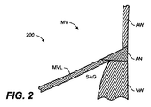
図2は、僧帽弁(MV)構造の一部分200の模式的な断面図を提供する。図示するように、一部分(200)は、僧帽弁弁尖(MVL)を含む。弁を取り囲む環(AN)も、示す。図2に示すように、SAGは、心室壁(VW)と僧帽弁輪(AN)の水平底面の接合により画定されるトラックである。同等のサブ環溝は、三尖弁の底面上に位置付けられ、本明細書に記載される方法および装置は、三尖弁に対しても使用されてもよい。
FIG. 2 provides a schematic cross-sectional view of a
SAGにアクセスするあらゆる適切な方法が、使用されてもよい。例えば、カテーテルは、大腿動脈に挿入されて、右心房(RA)、大動脈(A)の後ろの卵円孔の領域の心房間中隔を通され、左心室に挿入されてもよい。さらなる前進において、カテーテルの遠位部は、後外側の弁尖の下をSAGに自然と移動する。カテーテルは、弁の外周の周りを部分的または完全のいずれかで、SAGに沿ってさらに前進されてもよい。カテーテルが、下側から、僧帽弁弁尖(MVL)と室壁との交点、弁輪に隣接または非常に近くの環に位置することが、しばしば、望ましい。事前形成カテーテル(例えば、事前形成された遠位端または部分を有するカテーテル)の使用は、標的構造に適合することにより配置を補助してもよい。上述のアプローチは、大腿動脈を通したアクセスを利用するが、アクセスは、他の適切な血管(例えば、頚静脈動脈)を通して得られてもよい。 Any suitable method of accessing the SAG may be used. For example, the catheter may be inserted into the femoral artery, passed through the interatrial septum in the region of the foramen ovale behind the right atrium (RA), aorta (A), and inserted into the left ventricle. In further advancement, the distal portion of the catheter naturally moves under the posterior lateral leaflet to the SAG. The catheter may be further advanced along the SAG, either partially or completely around the circumference of the valve. It is often desirable for the catheter to be located from the underside at the intersection of the mitral valve leaflet (MVL) and the chamber wall, adjacent to or very close to the annulus. The use of a pre-formed catheter (eg, a catheter having a pre-formed distal end or portion) may assist in placement by adapting to the target structure. The above approach utilizes access through the femoral artery, but access may be obtained through other suitable blood vessels (eg, the jugular vein artery).
図3は、心臓弁輪の領域の中に少なくとも2つのアンカーを展開するための方法(300)のフローチャート図を提供する。ここで示すように、図示される方法は、SAG(310)にガイドカテーテルを前進させるステップと、ガイドカテーテル(320)の管腔を通ってガイドワイヤを前進させるステップと、ガイドワイヤ(330)上をトンネルカテーテルを前進させるステップと、トンネルカテーテル(340)からガイドワイヤを近位に引き抜くステップと、を含む。ガイドワイヤが、近位に引き抜かれた後、第1の送達カテーテルが、トンネルカテーテル(350)の管腔を通って前進されてもよく、第1のアンカーは、心臓弁輪(360)の第1の領域の中に展開されてもよい。第1のアンカーは、一般的に、しっかりと取り付けられるか、またはテザー等の誘導要素に固定される。これにより、アンカーが展開された後、誘導要素は、アンカーに取り付けられたままで、誘導要素は、その上のさらなる送達カテーテルの前進のためのトラックまたはモノレールとして使用されてもよい。 FIG. 3 provides a flowchart diagram of a method (300) for deploying at least two anchors in the region of the heart annulus. As shown herein, the illustrated method includes advancing a guide catheter through the SAG (310), advancing the guidewire through the lumen of the guide catheter (320), and over the guidewire (330). Advancing the tunnel catheter and withdrawing the guide wire proximally from the tunnel catheter (340). After the guide wire is withdrawn proximally, the first delivery catheter may be advanced through the lumen of the tunnel catheter (350), and the first anchor is the first of the heart annulus (360). One area may be expanded. The first anchor is typically securely attached or secured to a guiding element such as a tether. Thus, after the anchor is deployed, the guide element may remain attached to the anchor and the guide element may be used as a track or monorail for further delivery catheter advancement thereon.
誘導要素は、あらゆる適切な、または所望する生体適合材料で作られてもよい。誘導要素は、編組みされたまたは網組みされない、織られたまたは織られていない、さらなる材料で強化または含浸されていてもよく、あるいは単一材料または材料の組み合わせで作られてもよい。例えば、誘導要素は、縫合材料(例えば、ポリグリコール酸およびポリジオクサノン等の吸収縫合材料、シルク等の天然繊維、およびポリプロピレン、ポリエステル、ポリテトラフルオロエチレンで含浸されたポリエステル、ナイロン等の化学繊維)で作られてもよく、金属(吸収性または非吸収性)で作られてもよく、金属合金(例えば、ステンレススチール)で作られてもよく、形状記憶合金(例えば、ニッケルチタン合金)等の形状記憶素材で作られてもよく、その組み合わせで作られてもよく、または他のあらゆる生体適合材料で作られてもよい。いくつかの変形例において、近位に引っ張られる時、誘導要素は、僧帽弁輪の外周を締め付けるかまたは低減する。ある変形例において、誘導要素は、ワイヤの形態であってもよい。誘導要素は、複数の層を含んでもよい、および/または1つ以上の被覆を含んでもよい。例えば、誘導要素は、重合体被覆されたワイヤの形態であってもよい。ある変形例において、誘導要素は、1つ以上の縫合糸および1つ以上ワイヤの組み合わせの形態であってもよい。実施例として、誘導要素は、ワイヤで紐状にされた縫合糸の形態であってもよい。ある変形例において、誘導要素は、1つ以上の電極材料の形態であってもよい。ある変形例において、誘導要素は、遠隔情報(例えば、標的部位の状態に関して)を提供する1つ以上の材料の形態であってもよい。 The guide element may be made of any suitable or desired biocompatible material. The guide element may be braided or not braided, woven or non-woven, reinforced or impregnated with further materials, or may be made of a single material or a combination of materials. For example, the guide element may be a suture material (eg, absorbent suture materials such as polyglycolic acid and polydioxanone, natural fibers such as silk, and chemical fibers such as nylon impregnated with polypropylene, polyester, polytetrafluoroethylene, nylon, etc.) May be made of metal (absorbable or non-absorbable), may be made of metal alloy (eg, stainless steel), and shape such as shape memory alloy (eg, nickel titanium alloy) It may be made of a memory material, a combination thereof, or made of any other biocompatible material. In some variations, the guide element tightens or reduces the outer circumference of the mitral annulus when pulled proximally. In certain variations, the guide element may be in the form of a wire. The guide element may include multiple layers and / or may include one or more coatings. For example, the guide element may be in the form of a polymer-coated wire. In certain variations, the guide element may be in the form of a combination of one or more sutures and one or more wires. As an example, the guide element may be in the form of a suture threaded in a wire. In certain variations, the inductive element may be in the form of one or more electrode materials. In some variations, the guide element may be in the form of one or more materials that provide remote information (eg, regarding the condition of the target site).
ある変形例において、誘導要素は、1つ以上の治療剤(例えば、徐放性薬物等の薬物)を含んでもよい。実施例として、誘導要素は、1つ以上の治療剤で部分的または全体が被覆されてもよい。ある変形例において、誘導要素は、1つ以上の成長因子および/または遺伝子再生因子を送達するために使用されてもよい。ある変形例において、誘導要素は、1つ以上の治療剤を封入する材料(例えば、重合体)、または1つ以上の治療剤が内蔵されている材料で被覆されてもよい。治療剤は、例えば、誘導要素がしっかり取り付けられている、または別様に固定されている標的部位を治療するために使用されてもよい。ある変形例において、誘導要素は、治療剤が送達され得る1つ以上の管腔を含んでもよい。 In certain variations, the guide element may include one or more therapeutic agents (eg, a drug such as a sustained release drug). As an example, the guide element may be partially or wholly coated with one or more therapeutic agents. In certain variations, the inductive element may be used to deliver one or more growth factors and / or gene regeneration factors. In certain variations, the guide element may be coated with a material (eg, a polymer) that encapsulates one or more therapeutic agents, or a material that incorporates one or more therapeutic agents. The therapeutic agent may be used, for example, to treat a target site to which the guide element is securely attached or otherwise fixed. In certain variations, the guide element may include one or more lumens through which the therapeutic agent can be delivered.
第1のアンカーが、心臓弁輪の領域の中に展開された後、第1の送達カテーテルが近位に引き抜かれ、トンネルカテーテルがSAG(370)近くの異なる位置に位置付けられる。第2の送達カテーテルが、次に、トンネルカテーテル(380)の管腔を通って誘導要素上を前進される。誘導要素上の第2の送達カテーテルの前進中、誘導要素は、その遠位端の開口を通って第2の送達カテーテルに入り、その遠位端に近位である側壁の開口を通って第2の送達カテーテルを出てもよい。代替的に、誘導要素は、その遠位端の開口を通って第2の送達カテーテルに入り、その近位端の開口を通って第2の送達カテーテルを出てもよい。第2の送達カテーテルが、トンネルカテーテルの管腔を通って誘導要素上を前進された後、第2のアンカーが、心臓弁輪(390)の第2の領域の中へ展開される。 After the first anchor is deployed into the region of the heart annulus, the first delivery catheter is withdrawn proximally and the tunnel catheter is positioned at a different location near the SAG (370). The second delivery catheter is then advanced over the guide element through the lumen of the tunnel catheter (380). During advancement of the second delivery catheter over the guide element, the guide element enters the second delivery catheter through the opening at its distal end and passes through the opening in the sidewall that is proximal to the distal end. Two delivery catheters may exit. Alternatively, the guide element may enter the second delivery catheter through its distal end opening and exit the second delivery catheter through its proximal end opening. After the second delivery catheter is advanced over the guide element through the lumen of the tunnel catheter, the second anchor is deployed into the second region of the heart annulus (390).
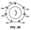
アンカーの数は、任意の数の適切な送達カテーテルを用いて、本方法を使用して展開されてもよい。例えば、ある場合において、図3Bおよび3Cに示すように、心臓弁輪の2つの異なる領域に2つのアンカーを展開することにより、僧帽弁輪の外周を低減することが所望されてもよい。図3Bおよび3C(以下の図3Dおよび3Eと同様)は、内側から透視的に見上げた模式的な図2の僧帽弁(MV)を示す。図3Bにおいて、前後形式で、僧帽弁に展開されるアンカー(392)を示すが、図3Cにおいて、横形式で展開されたアンカー(394)を示す。他の変形例において、環の領域の僧帽弁の近くに複数のセットのアンカーを展開することが所望されてもよい。例えば、図3Dにおいて、展開されたペアまたはセットの2つのアンカー(396)を示す。あらゆる数のアンカー、例えば、2つ、3つ、4つ、5つ、6つ、7つ等、がセットを形成してもよく、セットは、図3Dに示すように、環の近くに対称的、または均一に間隔をあける必要がないことを理解されたい。実際、いくつかの場合、他では所望されないが、1つのアンカーを強化することが所望されてもよく、これらの場合、単一とセットのアンカー展開の組み合わせであってもよい。また、アンカー(またはアンカーのセット)は、必要条件はないが、アンカー(398)を参照する図3Eに示すように、環の近くに対称的、または均一に間隔をあけて展開されてもよい。 The number of anchors may be deployed using this method using any number of suitable delivery catheters. For example, in some cases, as shown in FIGS. 3B and 3C, it may be desirable to reduce the outer circumference of the mitral annulus by deploying two anchors in two different regions of the heart annulus. FIGS. 3B and 3C (similar to FIGS. 3D and 3E below) show the schematic mitral valve (MV) of FIG. 2 as seen perspectively from the inside. In FIG. 3B, the anchor (392) deployed in the mitral valve is shown in anteroposterior format, while in FIG. In other variations, it may be desirable to deploy multiple sets of anchors near the mitral valve in the region of the annulus. For example, in FIG. 3D, two anchors (396) of a deployed pair or set are shown. Any number of anchors, eg 2, 3, 4, 5, 6, 7, etc., may form a set, the set being symmetrical near the ring, as shown in FIG. 3D It should be understood that there is no need for regular or even spacing. In fact, in some cases it may be desirable to reinforce one anchor, which is not desired elsewhere, and in these cases may be a combination of a single and a set of anchor deployments. Also, the anchor (or set of anchors) is not a requirement, but may be deployed symmetrically or uniformly spaced near the annulus as shown in FIG. 3E with reference to anchor (398). .
図3Aに示すフローチャート形式に示される方法は、複数の送達カテーテルを介して送達されるアンカーを示すが、他のアンカーの送達方法が使用されてもよいことも理解されたい。例えば、ある場合、参照によりその全体が本明細書に記載される、米国特許出願第11/201,949号でより詳しく記載されるように、単一の送達カテーテルから複数のアンカーを送達することが望ましい。同様に、単一の送達カテーテルを介した複数のアンカー送達および展開と、単一の送達カテーテルを介した単一のアンカー送達および展開とを組み合わせることが所望されてもよい。当業者は、処置および状況に最も適した数および種類のカテーテルを選択するだろう。 Although the method illustrated in the flow chart format shown in FIG. 3A shows an anchor being delivered via multiple delivery catheters, it should also be understood that other anchor delivery methods may be used. For example, in some cases, delivering multiple anchors from a single delivery catheter, as described in more detail in US patent application Ser. No. 11 / 201,949, hereby incorporated by reference in its entirety. Is desirable. Similarly, it may be desirable to combine multiple anchor delivery and deployment via a single delivery catheter with single anchor delivery and deployment via a single delivery catheter. One skilled in the art will select the number and type of catheters that are most appropriate for the procedure and situation.
図4A−4Iは、図3Aのフローチャート形式に示される方法のより詳しい図を提供する。図4A−4Iにおいて、図2の僧帽弁(MV)は、内側から透視的に見上げた模式的に示される。図4Aを参照すると、ガイドカテーテル(404)は、前述のあらゆるアクセス経路(または他の適切なアクセス経路)を使用してSAG(402)に前進される。ガイドカテーテル(404)が、SAG(402)の所望する位置に位置付けられた後、ガイドワイヤ(406)がガイドカテーテル(404)の管腔を通って前進される。ガイドワイヤ(406)は、ガイドカテーテル(404)の遠位端(408)を超えて前進され、ガイドワイヤ(406)は、図4Bに示すように、SAG(402)に沿ってガイドカテーテル(404)よりさらに延在する。 4A-4I provide a more detailed view of the method shown in the flowchart form of FIG. 3A. In FIGS. 4A-4I, the mitral valve (MV) of FIG. 2 is schematically shown looking up transparently from the inside. Referring to FIG. 4A, the guide catheter (404) is advanced to the SAG (402) using any of the previously described access paths (or other suitable access paths). After the guide catheter (404) is positioned at the desired location of the SAG (402), the guide wire (406) is advanced through the lumen of the guide catheter (404). The guidewire (406) is advanced over the distal end (408) of the guide catheter (404), and the guidewire (406) is moved along the SAG (402) as shown in FIG. 4B. ) Extends further.
ガイドワイヤ(406)がSAGに位置付けられた後、図4Cに示されるように、トンネルカテーテル(410)が、ガイドワイヤ(406)上を、ガイドカテーテル(404)を通って前進される。トンネルカテーテル(410)はあらゆる適切なカテーテルであってよく、ある場合において、上述のように、トンネルカテーテルは、図4Cに図示されるトンネルカテーテル等、遠位端で事前形成または事前成形されることが望さましい。ここで示されるように、トンネルカテーテルは、曲線を含む事前形成された遠位端を有する。このように、トンネルカテーテルは、僧帽弁の幾何形状により容易に適合してもよい。1つの遠位曲線が示されるが、本明細書に記載されるあらゆるカテーテルまたはガイドワイヤがあらゆる数の適切な曲線を含むように事前形成または事前成形されてもよいことを理解されたい。当然ながら、本明細書に記載されるガイドワイヤおよび/またはカテーテルは操縦可能であってもよい。 After the guidewire (406) is positioned in the SAG, the tunnel catheter (410) is advanced over the guidewire (406) through the guide catheter (404) as shown in FIG. 4C. The tunnel catheter (410) may be any suitable catheter, and in some cases, as described above, the tunnel catheter may be preformed or preformed at the distal end, such as the tunnel catheter illustrated in FIG. 4C. Is hopeful. As shown here, the tunnel catheter has a pre-formed distal end that includes a curve. In this way, the tunnel catheter may be more easily adapted to the mitral valve geometry. Although one distal curve is shown, it should be understood that any catheter or guidewire described herein may be preformed or preformed to include any number of suitable curves. Of course, the guidewires and / or catheters described herein may be steerable.
トンネルカテーテルも、SAGに対してカテーテルを固定するように構成される拡張可能な部材を備えてもよい。例えば、拡張部材は、組織の第2の部分に対してカテーテルを固定するために、組織の第1の部分に対して係合するように構成されてもよい。拡張可能部材は、あらゆる適切な拡張可能部材であってもよい。例えば、図13Aに示すように、低圧バルーン(1300)であってもよい。低圧バルーンは、シリコーン、ウレタン、天然ラテックス、ポリイソプレン、または他のゴムあるいはゴム重合体/混合(例えば、スチレン系ブロック共重合体、ポリオレフィン混合、ポリウレタン合金等)、その混合物の組み合わせ、または当該分野で周知の他の適切な弾性材料等の弾性材料で作られてもよい。いくつかの変形例において、弾性ポリウレタン合金が使用される。拡張可能部材も、ニッケルチタン合金等の形状記憶素材で作られてもよく、図13Bに示すように、ウィングまたはアーム(1302)、あるいは図13Cに示すように、バスケット(1304)の形状を有する。 The tunnel catheter may also include an expandable member configured to secure the catheter relative to the SAG. For example, the expansion member may be configured to engage against the first portion of tissue to secure the catheter relative to the second portion of tissue. The expandable member may be any suitable expandable member. For example, as shown in FIG. 13A, a low pressure balloon (1300) may be used. Low pressure balloons can be silicone, urethane, natural latex, polyisoprene, or other rubber or rubber polymers / mixes (eg, styrenic block copolymers, polyolefin blends, polyurethane alloys, etc.), combinations thereof, or the art May be made of an elastic material such as other suitable elastic materials known in In some variations, an elastic polyurethane alloy is used. The expandable member may also be made of a shape memory material such as a nickel titanium alloy and has the shape of a wing or arm (1302) as shown in FIG. 13B or a basket (1304) as shown in FIG. .
いくつかの変形例において、拡張部材は、加圧溶液(例えば、生理食塩水、生理食塩水:造影が75%/25%の混合等、造影剤との組み合わせの生理食塩水)を用いて膨張可能な、低圧弾性バルーンである。加圧溶液は、別の注入管腔を介してバルーンに送達されてもよい。注入管腔は、必要条件ではないが、送達カテーテルが前進される管腔と同軸であってもよい。例えば、注入管腔は、トンネルカテーテルの片側または両側に沿って位置してもよい。拡張部材の大きさは、固定される特定の生体組織に依存するが、SAG固定の場合、1/2インチから1インチの長さのバルーンが適切であり得る。バルーンの片側または両側が、膨張されるが、SAG固定の場合、SAGの反対側のみを膨張させることがより望ましい。このように、トンネルカテーテルは、押されてSAGとより並置して保持される。同様に、バルーンは、組織のある部分に対してより良く接合するために、その長さに沿って種々の剛性または硬さで膨張するように作られてもよい。 In some variations, the expansion member is expanded using a pressurized solution (eg, saline, saline: saline in combination with a contrast agent, such as 75% / 25% contrast contrast). Possible low pressure elastic balloon. The pressurized solution may be delivered to the balloon via a separate infusion lumen. The infusion lumen is not a requirement, but may be coaxial with the lumen through which the delivery catheter is advanced. For example, the infusion lumen may be located along one or both sides of the tunnel catheter. The size of the expansion member depends on the specific biological tissue to be fixed, but for SAG fixation, a balloon of 1/2 inch to 1 inch in length may be appropriate. One or both sides of the balloon are inflated, but for SAG fixation, it is more desirable to inflate only the opposite side of the SAG. Thus, the tunnel catheter is pushed and held in more juxtaposition with the SAG. Similarly, the balloon may be made to inflate with varying stiffness or hardness along its length to better bond to a portion of tissue.
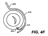
トンネルカテーテル(410)が、SAGに位置付けられた後、ガイドワイヤ(406)が図4Dに示すように、近位に引き抜かれる。ガイドワイヤ(406)が引き抜かれた後、送達カテーテル(412)が、次に、トンネルカテーテル(410)の管腔を通って前進されてもよい。図4Eに示すように、送達カテーテル(412)の遠位部(414)は、トンネルカテーテル(410)の遠位部(411)の開口(416)を通って前進される。次に、図4Fに示すように、誘導要素(テザー(422)として図4Gに示す)に取り付けられたアンカー(420)が、送達カテーテル(412)から展開される。アンカーは、詳細が送達カテーテルに焦点をあてる以下の詳細で記載されるように、あらゆる適切な形式で、送達カテーテルから展開される。例えば、アンカーは、押し引きワイヤ(例えば、遠位にワイヤを押すことにより、または近位にワイヤを引くことにより)を使用して、プランジャを使用して展開されるか、またはあらゆる他の適切な操作技術で展開されてもよい。同様に、アンカー(420)は、あらゆる適切な取り付け方法により、テザー(422)に取り付けられてもよい。例えば、1つ以上のノット、溶接領域および/または接着材が使用されてもよい。 After the tunnel catheter (410) is positioned in the SAG, the guide wire (406) is withdrawn proximally as shown in FIG. 4D. After the guide wire (406) is withdrawn, the delivery catheter (412) may then be advanced through the lumen of the tunnel catheter (410). As shown in FIG. 4E, the distal portion (414) of the delivery catheter (412) is advanced through the opening (416) in the distal portion (411) of the tunnel catheter (410). Next, as shown in FIG. 4F, an anchor (420) attached to a guiding element (shown in FIG. 4G as a tether (422)) is deployed from the delivery catheter (412). The anchor is deployed from the delivery catheter in any suitable manner, as described in the following details that focus on the delivery catheter. For example, the anchor is deployed using a plunger using a push-pull wire (eg, by pushing the wire distally or by pulling the wire proximally), or any other suitable May be deployed with various operating techniques. Similarly, anchor (420) may be attached to tether (422) by any suitable attachment method. For example, one or more knots, weld areas and / or adhesives may be used.
本明細書に記載される方法および装置に使用するためのアンカーは、あらゆる適切なアンカーであってもよい。アンカーは、あらゆる適切な材料で作られてもよく、あらゆる適切な大きさであってもよく、あらゆる適切な形状であってもよい。アンカーは、1つの材料または1つを超える材料で作られてもよい。アンカー材料の実施例は、超弾性またはニッケル−チタン合金およびスプリングステンレススチール等の形状記憶素材を含む。アンカー形状の実施例は、T−タグ、リベット、ステープル、フック(例えば、C形状または半円形フック、他の形状の湾曲フック、直線フック、棘のあるフック)、多重ループアンカー、およびクリップを含む。アンカーは、組織の中へ自己拡張して自己固定するように構成されてもよいが、このように構成される必要はない。さらに、単一誘導要素による同一の形状の複数のアンカーの送達および展開を記載するが、いくつかの変形例において、単一誘導要素は、異なる形状を有する複数のアンカーを送達および展開するために使用されてもよい。同様に、ある変形例において、単一誘導要素は、異なる大きさを有する複数のアンカーの送達および展開に使用されてもよい。適切なアンカーの例示的な実施例は、例えば、米国特許出願第11/202,474号でより詳しく記載されており、参照によりその全体が本明細書に記載される。 The anchor for use in the methods and devices described herein may be any suitable anchor. The anchor may be made of any suitable material, may be any suitable size, and may be any suitable shape. The anchor may be made of one material or more than one material. Examples of anchor materials include shape memory materials such as superelastic or nickel-titanium alloys and spring stainless steel. Examples of anchor shapes include T-tags, rivets, staples, hooks (eg, C-shaped or semi-circular hooks, other shaped curved hooks, straight hooks, barbed hooks), multiple loop anchors, and clips. . The anchor may be configured to self-expand and self-fix into the tissue, but need not be configured in this manner. Further, although the delivery and deployment of multiple anchors of the same shape by a single guide element is described, in some variations, the single guide element is used to deliver and deploy multiple anchors having different shapes. May be used. Similarly, in certain variations, a single guide element may be used for delivery and deployment of multiple anchors having different sizes. Exemplary examples of suitable anchors are described in more detail, for example, in US patent application Ser. No. 11 / 202,474, which is hereby incorporated by reference in its entirety.
図4Fに示すアンカー(420)は、送達カテーテル(412)を出る時に自己拡張し、僧帽弁輪(AN)の領域の中に自己固定する。アンカーは、弁輪組織の中に直接、またはSAGの近くの弁輪組織のわずかに下に展開されてもよいことを理解されたい。 The anchor (420) shown in FIG. 4F self-expands upon exiting the delivery catheter (412) and self-fixes within the region of the mitral annulus (AN). It should be understood that the anchor may be deployed directly into the annulus tissue or slightly below the annulus tissue near the SAG.
アンカー(420)が展開された後、送達カテーテル(412)が近位に引き抜かれる。図4Gは、テザー(422)に取り付けられ、僧帽弁輪(AN)に固定されるアンカー(420)を示す。図4Hに示すように、トンネルカテーテル(410)は、これから、SAGの異なる場所または位置に移動され、第2の送達カテーテル(424)が、図4Iに示すように、テザー(422)上を、トンネルカテーテル(410)の管腔を通って前進される。 After the anchor (420) is deployed, the delivery catheter (412) is withdrawn proximally. FIG. 4G shows the anchor (420) attached to the tether (422) and secured to the mitral annulus (AN). As shown in FIG. 4H, the tunnel catheter (410) is now moved to a different location or position of the SAG, and the second delivery catheter (424) moves over the tether (422) as shown in FIG. It is advanced through the lumen of the tunnel catheter (410).
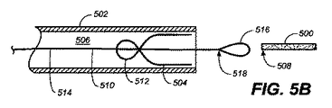
送達カテーテル(424)がトンネルカテーテル(410)を通って前進される前に、テザー(422)が、送達カテーテル(424)に通され、第2のアンカー(426)と摺動可能に係合される。あらゆる数の異なる方法が、テザー等の誘導要素を送達カテーテルに通すため、およびアンカーと誘導要素を係合するために使用されてもよい。例えば、図5A−5Dは、テザーを送達カテーテルに通すため、およびテザーをアンカーと摺動可能に係合するための投げ縄の使用を含む。投げ縄の使用により、テザーを送達カテーテルとアンカーに通すためにかかる時間量が低減され得る。図5Aに示すように、アンカー(504)は、送達カテーテル(502)の管腔(506)に予め装填され、テザー(500)の近位端(508)は、送達カテーテル(502)の近くにある。次に、図5Bを参照すると、投げ縄(510)は、管腔(506)に導入される。図5Cに示すように、投げ縄(510)は、アンカー(504)の小孔(512)を通され、テザー(500)を係合するために使用される。図5Dを参照すると、投げ縄(510)は、近位に引き抜かれることにより、小孔(512)を通してテザー(500)を引っ張る。 Before delivery catheter (424) is advanced through tunnel catheter (410), tether (422) is passed through delivery catheter (424) and slidably engaged with second anchor (426). The Any number of different methods may be used to pass a guide element, such as a tether, through the delivery catheter and to engage the anchor and guide element. For example, FIGS. 5A-5D include the use of a lasso to thread the tether through the delivery catheter and to slidably engage the tether with the anchor. The use of a lasso can reduce the amount of time it takes to pass the tether through the delivery catheter and anchor. As shown in FIG. 5A, the anchor (504) is preloaded into the lumen (506) of the delivery catheter (502) and the proximal end (508) of the tether (500) is near the delivery catheter (502). is there. Referring now to FIG. 5B, the lasso (510) is introduced into the lumen (506). As shown in FIG. 5C, the lasso (510) is threaded through the small hole (512) of the anchor (504) and used to engage the tether (500). Referring to FIG. 5D, the lasso (510) pulls the tether (500) through the stoma (512) by being pulled proximally.
図5B−5Dに示すように、投げ縄(510)は、ワイヤ部分(514)およびワイヤ部分の遠位端(518)のループ(516)を含む。ループ(516)は、一般的に、円形形状を示すが、いくつかの変形例において、投げ縄は、異なる形状を有するループを含むことができる。例えば、図6A−6Fは、異なる形状のループを有する投げ縄を示す。より具体的には、図6Aは、実質的に対称な円形ループ(602)の投げ縄(600)を示し、図6Bは、非対称的な円形ループ(612)の投げ縄(610)を示し、図6Cは、角形ループ(622)の投げ縄(620)を示し、図6Dは、三角形ループ(632)の投げ縄(630)を示し、図6Eは、ひし形ループ(642)の投げ縄(640)を示す。さらに、閉ループが誘導要素を係合するために示されるが、いくつかの変形例において、投げ縄は、フック等の開放型の誘導要素係合構造を含んでもよい。例えば、図6Fは、誘導要素を係合するために使用されてもよい一端で、フック(652)を用いた投げ縄(650)を示す。投げ縄の誘導要素係合構造は、投げ縄が通されるカテーテルの構造および/または通される誘導要素の種類により選択されてもよい。 As shown in FIGS. 5B-5D, the lasso (510) includes a wire portion (514) and a loop (516) at the distal end (518) of the wire portion. The loop (516) generally exhibits a circular shape, but in some variations, the lasso can include loops having different shapes. For example, FIGS. 6A-6F show a lasso having differently shaped loops. More specifically, FIG. 6A shows a substantially symmetrical circular loop (602) lasso (600), FIG. 6B shows an asymmetric circular loop (612) lasso (610), 6C shows a lasso (620) with a square loop (622), FIG. 6D shows a lasso (630) with a triangular loop (632), and FIG. 6E shows a lasso (640) with a diamond loop (642). ). Further, although a closed loop is shown for engaging the guide element, in some variations, the lasso may include an open guide element engagement structure such as a hook. For example, FIG. 6F shows a lasso (650) with a hook (652) at one end that may be used to engage a guide element. The lasso guide element engagement structure may be selected depending on the structure of the catheter through which the lasso is passed and / or the type of guide element being passed.
投げ縄は、例えば、1つ以上の金属、金属合金(例えば、ニッケル−チタン合金)および/または重合体を含むワイヤで形成されてもよい。ワイヤは、円形断面または非円形断面を有してもよい。投げ縄の誘導要素係合構造とワイヤ部とは、同一の材料または異なる材料で形成されてもよい。いくつかの変形例において、誘導要素係合構造は、ワイヤ部と一体構造に形成される。他の変形例において、誘導要素係合構造は、ワイヤ部に取り付けられる(例えば、溶接)。投げ縄または投げ縄(例えば、ループ)の一部は、比較的、可撓性であってもよい。この可撓性は、投げ縄が誘導要素の周りを屈曲および湾曲可することにより、誘導要素をより容易に係合できるよう投げ縄を補助し得る。ある変形例において、投げ縄の少なくとも一部が重合体シース等のシースおよび/または重合体被覆等の被覆で覆われるワイヤで形成されてもよい。シースまたは被覆の存在は、送達カテーテル管腔を通る投げ縄の通路を改善し得る。 The lasso may be formed of a wire comprising, for example, one or more metals, metal alloys (eg, nickel-titanium alloys) and / or polymers. The wire may have a circular cross section or a non-circular cross section. The lasso guide element engagement structure and the wire portion may be formed of the same material or different materials. In some variations, the guide element engagement structure is integrally formed with the wire portion. In other variations, the guide element engagement structure is attached to the wire portion (eg, welding). A lasso or a portion of a lasso (eg, a loop) may be relatively flexible. This flexibility may assist the lasso to more easily engage the guide element by allowing the lasso to bend and curve around the guide element. In certain variations, at least a portion of the lasso may be formed of a wire that is covered with a sheath such as a polymer sheath and / or a coating such as a polymer coating. The presence of the sheath or covering may improve the lasso passage through the delivery catheter lumen.
図5A−5Dは、送達カテーテルおよびアンカーを通してテザーを通すために投げ縄を使用することを含む方法を示すが、方法は、他の種類のカテーテル(例えば、ガイドカテーテル、シース、薬物送達カテーテル、治療用カテーテル、係止カテーテル、診断用カテーテル、器具カテーテル、切断カテーテル)および/または移植片を通ってテザー等の誘導要素を通すために使用されてもよい。 Although FIGS. 5A-5D illustrate a method that includes using a lasso to thread a tether through a delivery catheter and an anchor, the method may include other types of catheters (eg, guide catheters, sheaths, drug delivery catheters, treatments). Catheters, locking catheters, diagnostic catheters, instrument catheters, cutting catheters) and / or may be used to pass guide elements such as tethers through the graft.
実施例として、図7Aおよび7Bは、壁に形成された4つの開口(704、706、708および710)を有する壁(712)を備える管状部材(702)を含む係止カテーテル(700)を示す。誘導要素が締め付けられると(以下にさらなる詳細を記載するように)、係止カテーテルは、テザー等の誘導要素の張力を保持して、切断のために誘導要素を固定するために使用されてもよい。図7Aおよび7Bにおいて、テザー(714)は、穴(704、706、708および710)を通して係止カテーテル(700)に通される。テザーは、例えば、上述の投げ縄の1つ等、投げ縄を使用して、係止カテーテルに通されてもよい。投げ縄は、係止カテーテルの穴を通る投げ縄の操作性を改善し得る、比較的可撓性のループを有してもよい。テザー(714)が通される4つの穴を含むように係止カテーテル(700)を示すが、係止カテーテルは、他の数の穴を含んでもよい。例えば、係止カテーテルのいくつかの変形例は、より少ない穴(例えば、2つの穴)を含んでもよいが、係止カテーテルの他の変形例は、より多くの穴(例えば、6つの穴、8つの穴等)を含んでもよい。係止カテーテルの穴数が増えると、穴を通される誘導要素による移動の可能性が減少する。 As an example, FIGS. 7A and 7B show a locking catheter (700) comprising a tubular member (702) with a wall (712) having four openings (704, 706, 708 and 710) formed in the wall. . When the guide element is tightened (as described in further detail below), the locking catheter may be used to hold the guide element tension, such as a tether, to secure the guide element for cutting. Good. In FIGS. 7A and 7B, the tether (714) is passed through the locking catheter (700) through the holes (704, 706, 708 and 710). The tether may be passed through a locking catheter using a lasso, such as, for example, one of the lassos described above. The lasso may have a relatively flexible loop that may improve the operability of the lasso through the hole in the locking catheter. Although the locking catheter (700) is shown to include four holes through which the tether (714) is passed, the locking catheter may include other numbers of holes. For example, some variations of locking catheters may include fewer holes (eg, two holes), while other variations of locking catheters may have more holes (eg, six holes, 8 holes, etc.). As the number of holes in the locking catheter increases, the possibility of movement by the guide element being passed through the holes decreases.
糸を通す方法の1つの変形例を図5A−5Dに示すが、糸を通す方法の他の変形例を使用してもよい。例えば、いくつかの変形例において、糸通しロッド等の糸通し装置が、カテーテルを通して誘導要素を通すために使用されてもよい。誘導要素は、糸通しロッドの溝の周りに通されてもよい、および/または糸通しロッドの1つ以上の穴およびまたは管腔を通されてもよい。糸通しロッドは、誘導要素への支持を提供し得るので、カテーテルに誘導要素を通すのを容易にする。これは、したがって、全体の誘導要素を通す時間を短縮することができる。糸通し装置は、例えば、米国特許出願第11/232,190号に記載されるが、参照によりその全体が本明細書に記載される。 Although one variation of the threading method is shown in FIGS. 5A-5D, other variations of the threading method may be used. For example, in some variations, a threading device such as a threading rod may be used to pass the guiding element through the catheter. The guide element may be threaded around the threading rod groove and / or may be threaded through one or more holes and / or lumens of the threading rod. The threading rod may provide support to the guide element and thus facilitate passage of the guide element through the catheter. This can therefore reduce the time through the entire inductive element. The threading device is described, for example, in US patent application Ser. No. 11 / 232,190, which is described herein in its entirety by reference.
図8Aおよび4Iを参照すると、送達カテーテル(424)がトンネルカテーテル(410)を通って前進された後、送達カテーテル(424)は、トンネルカテーテル(410)の遠位端(411)の開口(416)を通って前進され、アンカー(426)を展開するために使用される。 Referring to FIGS. 8A and 41, after delivery catheter (424) has been advanced through tunnel catheter (410), delivery catheter (424) is open (416) at the distal end (411) of tunnel catheter (410). ) And is used to deploy the anchor (426).
図8Bは、外形を示すために直線にしたトンネルカテーテル(410)の断面図を示す。トンネルカテーテル(410)の壁(450)に形成される開口(416)は、円形または非円形であってもよい。図8Bに示すように、開口(416)は、開口の長さ、幅または径であってもよい外形(D)を有する。いくつかの変形例において、外形(D)が開口の幅である時等、外形(D)は、約0.08インチから約0.09インチであってもよい。ある変形例において、開口(416)が円形で外形(D)が開口の径である時等、外形(D)は、約0.09インチから約0.15インチであってもよい。いくつかの変形例において、外形(D)が開口の長さである時等、外形(D)は、約0.15インチから約0.2インチであってもよい。開口(416)は、例えば、レーザの使用等、あらゆる適切な技術を使用して、壁(450)に形成されてもよい。 FIG. 8B shows a cross-sectional view of the tunnel catheter (410) straightened to show the outer shape. The opening (416) formed in the wall (450) of the tunnel catheter (410) may be circular or non-circular. As shown in FIG. 8B, the opening (416) has an outer shape (D) that may be the length, width or diameter of the opening. In some variations, the profile (D) may be from about 0.08 inches to about 0.09 inches, such as when the profile (D) is the width of the opening. In some variations, the profile (D) may be from about 0.09 inches to about 0.15 inches, such as when the aperture (416) is circular and the profile (D) is the diameter of the aperture. In some variations, the profile (D) may be about 0.15 inches to about 0.2 inches, such as when the profile (D) is the length of the opening. The opening (416) may be formed in the wall (450) using any suitable technique, such as, for example, using a laser.
図8Bに示すように、トンネルカテーテル(410)は、内径(ID1)、外径(ОD1)、および長さ(L1)を有する。長さ(L1)は、例えば、約46インチから約48インチであってもよい。いくつかの変形例において、内径(ID1)は、約0.085インチから約0.1インチであってもよい。内径(ID1)は、例えば、送達カテーテル(424)の外形に基づき選択されてもよい。実施例として、送達カテーテル(424)が、比較的大きな外形を有する場合、内径(ID1)も、トンネルカテーテル(410)を通して、比較的迅速な送達カテーテル(424)の前進を提供するために、比較的大きくてもよい。いくつかの変形例において、外径(ОD1)は、約0.135インチから約0.15インチであってもよい。外径(ОD1)は、例えば、標的組織へのトンネルカテーテル(410)の前進のための計画された経路に基づき選択されてもよい。 As shown in FIG. 8B, the tunnel catheter (410) has an inner diameter (ID1), an outer diameter (OD1), and a length (L1). The length (L1) may be, for example, about 46 inches to about 48 inches. In some variations, the inner diameter (ID1) may be from about 0.085 inches to about 0.1 inches. The inner diameter (ID1) may be selected based on, for example, the outer shape of the delivery catheter (424). As an example, if the delivery catheter (424) has a relatively large profile, the inner diameter (ID1) is also compared to provide a relatively quick advancement of the delivery catheter (424) through the tunnel catheter (410). It may be large. In some variations, the outer diameter (OD1) may be from about 0.135 inches to about 0.15 inches. The outer diameter (OD1) may be selected, for example, based on the planned path for advancement of the tunnel catheter (410) to the target tissue.
トンネルカテーテル(410)は、あらゆる数の異なる材料で形成されてもよい。適切な材料の実施例は、ポリエーテル−ブロック−コポリアミド重合体等の重合体、コポリエステルエラストマ、熱硬化性重合体、ポリオレフィン(例えば、高密度ポリエチレンおよび低密度ポリエチレンを含む、ポリプロピレンまたはポリエチレン)、ポリテトラフルオロエチレン、エチレン酢酸ビニル、ポリアミド、ポリイミド、ポリウレタン、塩化ポリビニル(PVC、フルオロ重合体(例えば、フッ化エチレンプロピレン、ペルフルオロアルコキシ(PFA)重合体、ポリビニリデンフッ化物等)、ポリエーテルエーテルケトン(PEEKs)およびシリコーン等の重合体を含む。トンネルカテーテル(410)に含まれてもよいポリアミドの実施例は、Nylon6(例えば、DuPontTMのZytel(登録商標)HTN高性能ポリアミド)、Nylon11(例えば、Arkema Inc.のRilsan(登録商標)Bポリアミド)、およびNylon12(例えば、EMS−GrivoryのGrilamid(登録商標)ポリアミド、Arkema Inc.のRilsan(登録商標)Aポリアミド、およびDegussa Corp.Vestamid(登録商標)ポリアミド)を含む。いくつかの変形例において、トンネルカテーテル(410)は、複数の重合体で形成されてもよい。例えば、トンネルカテーテル(410)は、高密度ポリエチレンと低密度ポリエチレンの混合物等、異なる重合体の混合物で形成されてもよい。トンネルカテーテル(410)の壁(450)は、単一層で形成されるが、トンネルカテーテルのいくつかの変形例は、複数層(例えば、2層、3層)を有する壁を含んでもよい。さらに、トンネルカテーテルのいくつかの変形例は、異なる材料で形成された、および/または異なる数の層を含む、少なくとも2つの部分を含んでもよい。さらに、トンネルカテーテルのある変形例は、複数(例えば、2つ、3つ)の管腔を含んでもよい。管腔は、例えば、(例えば、編組みで)覆われる、および/または強化されてもよい。 The tunnel catheter (410) may be formed of any number of different materials. Examples of suitable materials are polymers such as polyether-block-copolyamide polymers, copolyester elastomers, thermosetting polymers, polyolefins (eg, polypropylene or polyethylene, including high density polyethylene and low density polyethylene) , Polytetrafluoroethylene, ethylene vinyl acetate, polyamide, polyimide, polyurethane, polyvinyl chloride (PVC, fluoropolymer (eg, fluoroethylenepropylene, perfluoroalkoxy (PFA) polymer, polyvinylidene fluoride, etc.), polyether ether) Examples of polyamides that may be included in the tunnel catheter (410) include Nylon 6 (eg, DuPont ™ Zytel® HTN High), including polymers such as ketones (PEEKs) and silicones. Performance polyamide), Nylon 11 (eg, Arkema Inc. Rilsan® B polyamide), and Nylon 12 (eg, EMS-Grivory Grilamid® polyamide, Arkema Inc. Rilsan® A polyamide), and In some variations, the tunnel catheter (410) may be formed of a plurality of polymers, for example, the tunnel catheter (410) is a high density polyethylene. The wall (450) of the tunnel catheter (410) is formed of a single layer, although some variations of the tunnel catheter are: It may include walls having several layers (eg, two layers, three layers) Further, some variations of tunnel catheters are made of different materials and / or include different numbers of layers. In addition, some variations of tunnel catheters may include multiple (eg, two, three) lumens that are covered (eg, with a braid), for example. And / or may be enhanced.
例えば、図14Aおよび14Bは、複数の管腔を有するトンネルカテーテル(1400)を示す。示すように、トンネルカテーテル(1400)は、近位部(1420)、移行部分(1430)、および遠位部(1440)を有し、主管腔(1404)および副管腔(1406)を画定する本体(1402)を含む。いくつかの変形例において、主管腔(1404)は、標的組織へカテーテルを前進されるために使用されてもよいが、副管腔(1406)は、膨張管腔として使用されてもよい。例えば、副管腔(1406)は、トンネルカテーテルに着装されるバルーンを膨張させるために、25%の造影剤と75%のヘパリン化生理食塩水の混合物で注入されてもよい。主管腔(1404)は、編組強化(1410)を含むライナー(1408)で裏打ちされ、副管腔(1406)は、編組強化(1414)を含むライナー(1412)で同様に裏打ちされる。 For example, FIGS. 14A and 14B show a tunnel catheter (1400) having multiple lumens. As shown, tunnel catheter (1400) has a proximal portion (1420), a transition portion (1430), and a distal portion (1440) and defines a main lumen (1404) and a secondary lumen (1406). Including a body (1402). In some variations, the main lumen (1404) may be used to advance the catheter to the target tissue, while the secondary lumen (1406) may be used as the inflation lumen. For example, the secondary lumen (1406) may be infused with a mixture of 25% contrast agent and 75% heparinized saline to inflate the balloon worn on the tunnel catheter. The main lumen (1404) is lined with a liner (1408) that includes braid reinforcement (1410), and the secondary lumen (1406) is similarly lined with a liner (1412) that includes braid reinforcement (1414).
本体(1402)は、1つ以上の重合体等の1つ以上の材料で形成されてもよい。例えば、いくつかの変形例において、本体(1402)の近位部(1420)は、高密度ポリエチレン(HDPE)および低密度ポリエチレン(LDPE)の混合物で形成されてもよく、本体(1402)の移行部分(1430)は、DuPontTM20低密度ポリエチレン(DuPontTM)で形成されてもよく、遠位部(1440)は、Elvax(登録商標)450エチレン酢酸ビニル(DuPontTM)で形成されてもよい。このような変形例において、近位部(1420)は、長さが約28インチであってもよく、移行部分(1430)は、長さが約8インチであってもよく、遠位部(1440)は、長さが約10インチであってもよい。しかしながら、他の長さが近位部、移行部および遠位部に使用されてもよい。
The body (1402) may be formed of one or more materials, such as one or more polymers. For example, in some variations, the proximal portion (1420) of the body (1402) may be formed of a mixture of high density polyethylene (HDPE) and low density polyethylene (LDPE), and the transition of the body (1402) Portion (1430) may be formed of DuPont ™ 20 low density polyethylene (DuPont ™ ) and distal portion (1440) may be formed of
ライナー(1408)は、高密度ポリエチレンまたはポリテトラフルオロエチレン(例えば、エッチングされたポリテトラフルオロエチレン)で形成されてもよく、ライナー(1412)は、扁平なポリイミドで形成されてもよい。編組強化(1410)および(1414)は、同一の材料または異なる材料で形成されてもよい。片方または両方の編組強化に適切な材料の実施例は、304Vステンレススチール等のステンレススチールである。 The liner (1408) may be formed of high density polyethylene or polytetrafluoroethylene (eg, etched polytetrafluoroethylene), and the liner (1412) may be formed of flat polyimide. The braid reinforcements (1410) and (1414) may be formed of the same material or different materials. An example of a material suitable for one or both braid reinforcements is stainless steel, such as 304V stainless steel.
図8Aおよび8Bは、トンネルカテーテルの一変形例を示すが、トンネルカテーテルの他の変形例も、標的部位へ送達カテーテルを前進させるために使用されてもよいことを理解されたい。例えば、図9は、送達カテーテル(902)がトンネルカテーテル(900)の遠位端(904)を抜けて通るように前進される、トンネルカテーテル(900)を示す。 8A and 8B illustrate one variation of a tunnel catheter, it should be understood that other variations of the tunnel catheter may also be used to advance the delivery catheter to the target site. For example, FIG. 9 shows tunnel catheter (900) being advanced so that delivery catheter (902) passes through the distal end (904) of tunnel catheter (900).
図8Cは、外形を示すために直線にした送達カテーテル(424)の断面図を提供する。図8Cに示すように、送達カテーテル(424)は、内径(ID2)、外径(ОD2)および長さ(L2)を有する。長さ(L2)は、例えば、約120センチメートルから約150センチメートルであってもよい。いくつかの変形例において、内径(ID2)は、0.045インチから約0.06インチであってもよい。内径(ID2)は、例えば、送達カテーテルから展開されるアンカーの大きさおよび/または種類に基づき選択されてもよい。ある変形例において、外径(ОD2)は、約0.07インチから約0.095インチであってもよい。 FIG. 8C provides a cross-sectional view of delivery catheter (424) straightened to show the outline. As shown in FIG. 8C, the delivery catheter (424) has an inner diameter (ID2), an outer diameter (OD2), and a length (L2). The length (L2) may be, for example, about 120 centimeters to about 150 centimeters. In some variations, the inner diameter (ID2) may be from 0.045 inches to about 0.06 inches. The inner diameter (ID2) may be selected based on, for example, the size and / or type of anchor deployed from the delivery catheter. In some variations, the outer diameter (OD2) may be about 0.07 inches to about 0.095 inches.
送達カテーテル(424)は、あらゆる数の異なる材料で形成されてもよい。適切な材料の実施例は、トンネルカテーテル(410)を参照にした上述の重合体等の重合体、金属(例えば、プラチナ、金)、金属合金(例えば、ニチノール等のニッケル−チタン合金)、およびこれらの材料の組み合わせを含む。送達カテーテル(424)は、トンネルカテーテル(410)等と同一のいくつかまたは全ての材料で形成されるか、またはトンネルカテーテル(410)と異なる材料で形成されてもよい。送達カテーテル(424)は、1つの層で形成される壁(425)を含むように示されるが、送達カテーテルのいくつかの変形例は、複数の層で形成される壁を含んでもよい。さらに、送達カテーテルは、異なる材料で形成される、および/または異なる数の層を含む、少なくとも2つの部分を含んでもよい。 Delivery catheter (424) may be formed of any number of different materials. Examples of suitable materials include polymers such as those mentioned above with reference to tunnel catheter (410), metals (eg, platinum, gold), metal alloys (eg, nickel-titanium alloys such as nitinol), and Includes combinations of these materials. Delivery catheter (424) may be formed of some or all of the same materials as tunnel catheter (410) or the like, or may be formed of a different material than tunnel catheter (410). Although the delivery catheter (424) is shown to include a wall (425) formed of one layer, some variations of the delivery catheter may include a wall formed of multiple layers. Further, the delivery catheter may include at least two portions that are formed of different materials and / or include different numbers of layers.
図8Cは、送達カテーテルの一変形例を示すが、あらゆる数の異なる種類および構造の送達カテーテルが移植片送達に使用されてもよい。送達カテーテルは、1つの管腔または複数(例えば、2つ、3つ)の管腔を有してもよい。いくつかの変形例において、送達カテーテルの一部分は、送達カテーテルの他の部分より少ない数の管腔を有してもよい。例えば、送達カテーテルの遠位部は、1つの管腔を有するが、送達カテーテルの近位部は、2つまたは3つの管腔を有してもよい。送達カテーテルの管腔は、例えば、誘導要素管腔および/または注入管腔(例えば、標的組織への1つ以上の治療剤の注入のため)であってもよい。管腔は、送達カテーテルの種々の異なる領域に位置してもよい。例えば、送達カテーテルは、略管状部材および略管状部材の表面に形成される管腔を含んでもよい。送達カテーテルの管腔は、送達カテーテルの長さに沿って延在してもよく、送達カテーテルより短くてもよく、または2つの組み合わせであってもよい。さらに、管腔は、送達カテーテルの遠位部のみ、または送達カテーテルの近位部にのみに位置してもよい。さらに、送達カテーテルまたは他の種類のカテーテルのある変形例は、誘導要素が通されてもよい他の構造を含んでもよい。実施例として、送達カテーテルのいくつかの変形例は、外表面上にスロット領域を含んでもよい。スロット領域は、例えば、誘導要素上を送達カテーテルを通すために使用されてもよい。 Although FIG. 8C shows one variation of a delivery catheter, any number of different types and structures of delivery catheters may be used for graft delivery. The delivery catheter may have one lumen or multiple (eg, two, three) lumens. In some variations, a portion of the delivery catheter may have a fewer number of lumens than other portions of the delivery catheter. For example, the distal portion of the delivery catheter has one lumen, but the proximal portion of the delivery catheter may have two or three lumens. The lumen of the delivery catheter may be, for example, a guide element lumen and / or an injection lumen (eg, for injection of one or more therapeutic agents into the target tissue). The lumen may be located in a variety of different areas of the delivery catheter. For example, the delivery catheter may include a generally tubular member and a lumen formed on a surface of the generally tubular member. The lumen of the delivery catheter may extend along the length of the delivery catheter, may be shorter than the delivery catheter, or may be a combination of the two. Further, the lumen may be located only at the distal portion of the delivery catheter or only at the proximal portion of the delivery catheter. In addition, certain variations of delivery catheters or other types of catheters may include other structures through which guide elements may be threaded. As an example, some variations of the delivery catheter may include a slot region on the outer surface. The slot region may be used, for example, to pass a delivery catheter over the guide element.
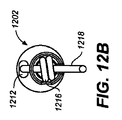
図12A−12Dは、標的部位に1つ以上のアンカーを送達するために使用されてもよい、種々の送達カテーテル(1200)の異なる詳細図を示す。図12Aに示すように、送達カテーテル(1200)は、先端(1202)を含む遠位領域(1204)、主管腔(1208)を含むアンカー保持領域(1206)、主管腔(1208)および副管腔(1212)の両方を含む中間領域(1210)、および主管腔(1208)を含む近位領域(1214)を有する。アンカー(1216)は、アンカー保持領域(1206)の主管腔(1208)内に配置される。1つのアンカーのみが、アンカー保持領域に示されるが、送達カテーテルのいくつかの変形例は、複数のアンカーを保持するようになっているアンカー保持領域を含んでもよい。同様に、図12A−12Dに示される変形例は、送達カテーテルの遠位端から展開されるようになっているアンカーを示すが、アンカーは、所望に応じて、送達カテーテルのあらゆる適切な領域から展開されてもよいことを理解されたい。例えば、所望に応じて、アンカーは、送達カテーテルのサイドポートまたは穴の外から送達されてもよい。 12A-12D show different detailed views of various delivery catheters (1200) that may be used to deliver one or more anchors to a target site. As shown in FIG. 12A, the delivery catheter (1200) includes a distal region (1204) that includes a tip (1202), an anchor retention region (1206) that includes a main lumen (1208), a main lumen (1208), and a secondary lumen. (1212) having an intermediate region (1210) and a proximal region (1214) including a main lumen (1208). Anchor (1216) is disposed within main lumen (1208) of anchor retention region (1206). Although only one anchor is shown in the anchor retention region, some variations of the delivery catheter may include an anchor retention region that is adapted to retain multiple anchors. Similarly, the variation shown in FIGS. 12A-12D shows an anchor that is adapted to be deployed from the distal end of the delivery catheter, but the anchor can be removed from any suitable region of the delivery catheter as desired. It should be understood that it may be deployed. For example, if desired, the anchor may be delivered from outside a delivery catheter side port or hole.
図12A−12Dに示すように、テザー(1218)は、先端(1202)のスロット(1219)に通され(図12Cおよび12Dに示される)、アンカー(1216)の小孔(1226)に通される。図12Cに示すように、小孔を通って延在した後、テザーは、主管腔(1208)を出て、アンカー保持領域の残りの長さに対する送達カテーテル(1200)の外表面(1221)に沿って延在する。テザーは、次に、副管腔(1212)に入り、副管腔に沿って延在し、遠位領域(1214)の端で副管腔を出る。アクチュエータ(1220)が、主管腔(1208)内に摺動可能に展開され、アンカー(1216)を展開するために使用されてもよい。他の形状のアクチュエータが使用されてもよいが、アクチュエータは、押し込み可能な略管状部材の形状である。例えば、いくつかの変形例において、中実のロッドがアクチュエータとして使用されてもよい。 As shown in FIGS. 12A-12D, the tether (1218) is threaded through the slot (1219) in the tip (1202) (shown in FIGS. 12C and 12D) and through the stoma (1226) in the anchor (1216). The After extending through the stoma, the tether exits the main lumen (1208) and onto the outer surface (1221) of the delivery catheter (1200) for the remaining length of the anchor retention region, as shown in FIG. 12C. Extending along. The tether then enters the secondary lumen (1212), extends along the secondary lumen, and exits the secondary lumen at the end of the distal region (1214). An actuator (1220) may be slidably deployed in the main lumen (1208) and used to deploy the anchor (1216). Although other shaped actuators may be used, the actuator is in the form of a pushable generally tubular member. For example, in some variations, a solid rod may be used as the actuator.
回収縫合糸(1224)が、アクチュエータ(1220)内に摺動可能に配置され、アクチュエータの遠位端(1222)を超えて延在する。回収縫合糸は、アンカー(1216)と係合されるように、アンカー(1216)の小孔(1226)を通って輪になる。これにより、間違って発射または間違って配置されたアンカーは、再展開するために送達カテーテル(1200)内に近位に回収されてもよい。アンカーの適切な展開後、回収縫合糸も、もちろん、アンカー(1216)から外されることが可能である。いくつかの変形例において、回収縫合糸は、回収縫合糸の近位端上を引っ張ることにより、およびアンカー小孔およびカテーテルから回収縫合糸を引き抜くことにより、アンカーから外されてもよい。回収縫合糸(1224)は、例えば、上述のあらゆるテザー材料で形成されてもよい。さらに、回収縫合糸を含む送達カテーテルが記載されるが、いくつかの変形例において、送達カテーテルは、回収縫合糸を含まなくてもよい、または複数の回収縫合糸を含んでもよい。 A retrieval suture (1224) is slidably disposed within the actuator (1220) and extends beyond the distal end (1222) of the actuator. The retrieval suture loops through the small hole (1226) of the anchor (1216) so that it is engaged with the anchor (1216). Thereby, misfired or misplaced anchors may be retrieved proximally within delivery catheter (1200) for redeployment. After proper deployment of the anchor, the retrieval suture can, of course, be removed from the anchor (1216). In some variations, the retrieval suture may be removed from the anchor by pulling over the proximal end of the retrieval suture and by withdrawing the retrieval suture from the anchor ostium and catheter. The retrieval suture (1224) may be formed of any of the tether materials described above, for example. Further, although a delivery catheter is described that includes a retrieval suture, in some variations, the delivery catheter may not include a retrieval suture or may include a plurality of retrieval sutures.
アンカー(426)は、送達カテーテル(424)を出ると、僧帽弁輪(AN)の領域の組織に自己拡張して自己固定する。前の図を参照すると、図4Iに示すように、アンカー(426)は、アンカー(420)から僧帽弁輪の異なる領域に自己固定する。 As anchor (426) exits delivery catheter (424), it self-expands and self-fixates to tissue in the region of the mitral annulus (AN). Referring to the previous figure, as shown in FIG. 4I, anchor (426) self-fixes from anchor (420) to different regions of the mitral annulus.
図4Jは、アンカー(420)がテザー(422)にしっかり固定されるが、アンカー(426)はテザー(422)に摺動可能に連結されることを示す。より具体的には、アンカー(420)は、結合点(440)でテザーに固定して取り付けされる小孔(436)を含み、アンカー(426)は、テザーが通される小孔(438)を含む。小孔(436)を通るテザーの通しは、アンカー(426)がテザーと摺動可能に連結されることを生じる。したがって、テザーが締め付けられると、テザーは、次に、小孔(436)を通って摺動する。テザー(422)は、このように複数のアンカーを通されてもよい。 FIG. 4J shows that anchor (420) is secured to tether (422), but anchor (426) is slidably coupled to tether (422). More specifically, the anchor (420) includes a small hole (436) that is fixedly attached to the tether at the point of attachment (440), and the anchor (426) includes a small hole (438) through which the tether is passed. including. The passage of the tether through the stoma (436) results in the anchor (426) being slidably coupled with the tether. Thus, when the tether is tightened, the tether then slides through the stoma (436). The tether (422) may thus be threaded through multiple anchors.
上に記載するように、図4A−4Iを参照に記載される方法は、僧帽弁輪(AN)の種々の領域に自己固定できる複数(例えば、少なくとも2つ、少なくとも3つ)のアンカーを展開するように反復されてもよい。実施例として、いくつかの変形例において、5つの異なる送達カテーテルが、異なる領域の僧帽弁輪に5つのアンカーを展開するように単一テザー上を連続的に前進されてもよい。別の実施例として、ある変形例において、8つのアンカーが、約240°の円弧に沿って、僧帽弁輪に展開されてもよい。この場合も、展開されたアンカーは、均一に間隔をあけるか、または、アンカー間で種々の間隔を有してもよい。複数のアンカーが僧帽弁輪の領域に固定された後、テザー(422)は、締め付けられることにより、互いに近くアンカーを引っ張り、僧帽弁輪の外周を低減する。 As described above, the method described with reference to FIGS. 4A-4I employs multiple (eg, at least two, at least three) anchors that can be self-fixed to various regions of the mitral annulus (AN). It may be repeated to unfold. As an example, in some variations, five different delivery catheters may be successively advanced over a single tether to deploy five anchors in different regions of the mitral annulus. As another example, in one variation, eight anchors may be deployed to the mitral annulus along an arc of about 240 °. Again, the deployed anchors may be evenly spaced or may have various spacings between the anchors. After the plurality of anchors are secured in the region of the mitral annulus, the tether (422) is tightened to pull the anchors closer together and reduce the circumference of the mitral annulus.
テザー(422)は、所望の程度に低減が達成(例えば、超音波および蛍光透視により判断される)された後、終端されてもよい。実施例として、クリップが、アンカー間のテザー(422)の張力を保持するために、最近位のアンカーの近位にあるテザー(422)に取り付けられてもよい。テザー(422)は、次に、クリップの近位で切断されてもよい。以下にさらなる詳細を記載するように、いくつかの変形例において、取り付けおよび切断は、終端カテーテル等の終端装置を使用して達成されてもよい。例えば、1つ以上の切断および/または係止カテーテルは、締め付けが完了した後、締め付けられた誘導要素での張力を保持するため、および誘導要素の未使用部分を除去するために使用されてもよい。終端装置は、例えば、米国特許出願第11/232,190号および第11/270,034号に記載され、これら両方は、参照によりその全体が本明細書に記載される。 The tether (422) may be terminated after a reduction is achieved to a desired degree (eg, as determined by ultrasound and fluoroscopy). As an example, a clip may be attached to the tether (422) proximal to the proximal anchor to retain the tension of the tether (422) between the anchors. The tether (422) may then be cut proximal to the clip. As described in further detail below, in some variations, attachment and cutting may be accomplished using a termination device, such as a termination catheter. For example, one or more cutting and / or locking catheters may be used to maintain tension on the clamped guide element and to remove unused portions of the guide element after clamping is complete. Good. Termination devices are described, for example, in US patent application Ser. Nos. 11 / 232,190 and 11 / 270,034, both of which are hereby incorporated by reference in their entirety.
テザー(422)を終端するいくつかの方法は、テザー(422)上を終端カテーテルを最近位のアンカーに前進する前に、ガイドカテーテル(404)からトンネルカテーテル(410)を引き抜くステップを含んでもよい。終端カテーテルは、次に、テザー(422)の取り付けおよび切断のために使用されてもよい。他の方法は、テザー(422)の張力を保持するために、最初に、最近位のアンカーの近位のテザー(422)にクリップを取り付け、次に、ガイドカテーテル(404)からトンネルカテーテル(410)を引き抜くステップを含んでもよい。ある変形例において、方法は、最近位の固定されたアンカーにテザー(422)を取り付け、次に、テザー(422)が取り付けられたアンカーに対し近位でテザー(422)を切断するステップを含んでもよい。テザー(422)は、例えば、1つ以上の接着材および/または1つ以上の結紮、圧接および/または結束技術を使用して、最近位のアンカーに取り付けられてもよい。通し、締め付け、および終端技術がテザーに対して記載されたが、これらの技術は、他の誘導要素と使用されてもよい。 Some methods of terminating the tether (422) may include withdrawing the tunnel catheter (410) from the guide catheter (404) before advancing the termination catheter over the tether (422) to the nearest anchor. . The end catheter may then be used for attachment and cutting of the tether (422). Another method is to first attach a clip to the proximal tether (422) of the proximal anchor, and then from the guide catheter (404) to the tunnel catheter (410) to maintain the tension of the tether (422). ) May be included. In certain variations, the method includes attaching the tether (422) to the nearest fixed anchor and then cutting the tether (422) proximal to the anchor to which the tether (422) is attached. But you can. The tether (422) may be attached to the proximal anchor using, for example, one or more adhesives and / or one or more ligating, crimping and / or tying techniques. Although threading, clamping, and termination techniques have been described for tethers, these techniques may be used with other inductive elements.
誘導要素は、数多くの異なる方法のいずれかで、終端カテーテルに通されてもよい。例えば、図10A−10Eは、係止カテーテルを通る異なるテザー経路の実施例を示し、図11A−11Cは、切断カテーテルを通る異なるテザー経路の実施例を示す。 The guide element may be passed through the end catheter in any of a number of different ways. For example, FIGS. 10A-10E show examples of different tether paths through the locking catheter, and FIGS. 11A-11C show examples of different tether paths through the cutting catheter.
図10Aを参照すると、係止カテーテル(1000)は、先端(1002)およびシャフト(1004)を含む。係止カテーテルがテザーを固定することにより、テザーの張力を保持できるように、テザー(1006)は、先端の4つの開口に通される。テザー(1006)は、先端(1002)の4つの開口に通されるが、誘導要素は、カテーテル先端の異なる数の開口に通されてもよい。例えば、図10Bは、先端(1015)および係止カテーテルの先端の2つの開口に通されたテザー(1016)を含む、係止カテーテル(1014)を示す。図10Cにおいて、テザー(1018)は、係止カテーテル(1024)の先端(1022)の3つの開口に通され、係止カテーテルのシャフト(1026)にも通される。テザーは、シャフトの開口を通って最終的にシャフトを出る。図10Dは、係止カテーテル(1036)の先端(1034)の遠位端(1031)に通され、係止カテーテルのシャフト(1040)を通って延在し、シャフトの開口を通って出る、テザー(1030)を示す。誘導要素は、送達カテーテルのシャフトの異なる長さを通って延在してもよい。例えば、図10Dのテザーは、比較的短い長さのカテーテルシャフトを通って延在するが、図10Eは、比較的長い長さのカテーテルシャフトを通って延在するテザーを示す。図10Eに示すように、テザー(1042)は、係止カテーテル(1048)の先端(1046)の開口に通され、係止カテーテルのシャフト(1050)の略全長を通って延在する。テザー(1042)は、シャフトの近位端(1051)の開口を通ってシャフトを出る。 Referring to FIG. 10A, the locking catheter (1000) includes a tip (1002) and a shaft (1004). The tether (1006) is threaded through the four openings at the tip so that the locking catheter can hold the tether tension by securing the tether. The tether (1006) is threaded through the four openings in the tip (1002), but the guide element may be threaded through a different number of openings in the catheter tip. For example, FIG. 10B shows a locking catheter (1014) that includes a tip (1015) and a tether (1016) threaded through two openings at the tip of the locking catheter. In FIG. 10C, the tether (1018) is threaded through three openings at the tip (1022) of the locking catheter (1024) and also through the locking catheter shaft (1026). The tether finally exits the shaft through the shaft opening. FIG. 10D shows the tether being passed through the distal end (1031) of the tip (1034) of the locking catheter (1036), extending through the shaft (1040) of the locking catheter, and exiting through the opening in the shaft. (1030) is shown. The guide element may extend through different lengths of the delivery catheter shaft. For example, the tether of FIG. 10D extends through a relatively short length of the catheter shaft, while FIG. 10E shows a tether extending through a relatively long length of the catheter shaft. As shown in FIG. 10E, the tether (1042) is threaded through the opening at the tip (1046) of the locking catheter (1048) and extends through substantially the entire length of the locking catheter shaft (1050). Tether (1042) exits the shaft through an opening in the proximal end (1051) of the shaft.
上に記載するように、誘導要素も、異なる経路構造の切断カテーテルを通ってもよい。例えば、図11Aは、先端部分(1102)およびシャフト部分(1104)を含む、切断カテーテル(1100)を示す。テザー(1106)は、先端部分(1102)の2つの開口に通される。切断要素(1108)は、シャフト部分(1104)の管腔内に配置され、(例えば、締め付け処置が実施された後)テザーを切断するために使用されてもよい。図11Bは、切断カテーテルを通されるテザーの異なる経路構造を示す。図11Bに示すように、切断カテーテル(1110)は、切断要素(1118)を含む先端部分(1112)およびシャフト部分(1114)を含む。テザー(1116)は、遠位端(1119)で先端部分(1112)に入って、先端部分の3つの開口に通される。図11Cを参照すると、切断カテーテル(1120)は、先端部分(1122)およびシャフト部分(1124)を含む。テザー(1126)は、遠位端(1127)で先端部分(1122)に入って、遠位端(1127)に対し近位である開口を通って先端部分を出る。切断要素(1128)は、シャフト部分(1124)内に配置される。誘導要素は、切断カテーテルの異なる数の穴および/または切断カテーテルの異なる位置に通されてもよい。記載される通し変形例の全ては、適切な通し技術の単なる例示的な実施例にすぎない。 As described above, the guide element may also pass through different pathway structure cutting catheters. For example, FIG. 11A shows a cutting catheter (1100) that includes a tip portion (1102) and a shaft portion (1104). Tether (1106) is threaded through two openings in tip portion (1102). Cutting element (1108) is disposed within the lumen of shaft portion (1104) and may be used to cut the tether (eg, after a tightening procedure has been performed). FIG. 11B shows a different path structure for the tether being passed through the cutting catheter. As shown in FIG. 11B, the cutting catheter (1110) includes a tip portion (1112) that includes a cutting element (1118) and a shaft portion (1114). The tether (1116) enters the tip portion (1112) at the distal end (1119) and is threaded through the three openings in the tip portion. Referring to FIG. 11C, the cutting catheter (1120) includes a tip portion (1122) and a shaft portion (1124). Tether (1126) enters tip portion (1122) at distal end (1127) and exits the tip portion through an opening proximal to distal end (1127). Cutting element (1128) is disposed within shaft portion (1124). The guide element may be passed through different numbers of holes in the cutting catheter and / or different locations on the cutting catheter. All of the threading variations described are merely exemplary examples of suitable threading techniques.
さらに、係止カテーテルおよび切断カテーテルを通る誘導要素の経路構造が示されるが、経路構造は、他種類のカテーテルで使用されてもよい。さらに、他の経路構造が、カテーテルを通って誘導要素を通すために使用されてもよい。実施例として、いくつかの変形例において、誘導要素は、カテーテルの先端を通らなくてもよい。 Furthermore, although the routing structure of the guide element through the locking catheter and the cutting catheter is shown, the routing structure may be used with other types of catheters. In addition, other pathway structures may be used to pass the guide element through the catheter. As an example, in some variations, the guide element may not pass through the tip of the catheter.
本明細書に記載される方法は、アンカー展開に対して記載されたが、方法は、あらゆる数および/または種類の適切な移植片を展開するために使用されてもよい。例えば、移植片は、1つ以上のアンカーを含んでもよく、リードまたは電極(例えば、ペーシング電極、診断用電極、活性電極)を含んでもよく、または他のあらゆる適切な移植片を含んでもよい。いくつかの変形例において、移植片は、単一または1つ以上のアンカーとの組み合わせで、布移植片また弁成形リングを含んでもよい。さらに、移植片の実施例は、薬物送達移植片等の治療を送達する移植片、および標的部位の状態についての情報等の遠隔情報の移植片を含む。例えば、移植片は、成長因子および/または遺伝子再生因子を送達するために使用されてもよい。移植片は、例えば、米国特許出願第10/461,043号、第10/656,797号、第10/741,130号、第10/776,682号、第10/792,681号、第10/901,019号、第10/901,555号、第10/901,554号、第10/901,445号および第10/901,444号に記載され、全て、参照によりその全体が本明細書に記載される。 Although the method described herein has been described for anchor deployment, the method may be used to deploy any number and / or type of suitable implants. For example, the implant may include one or more anchors, may include a lead or electrode (eg, a pacing electrode, a diagnostic electrode, an active electrode), or may include any other suitable implant. In some variations, the implant may include a fabric graft or an annuloplasty ring, in combination with a single or one or more anchors. In addition, examples of implants include implants that deliver therapy, such as drug delivery implants, and implants of remote information, such as information about the condition of the target site. For example, the graft may be used to deliver growth factors and / or gene regeneration factors. For example, US Pat. Nos. 10 / 461,043, 10 / 656,797, 10 / 741,130, 10 / 776,682, 10 / 792,681, 10 / 9011,019, 10 / 901,555, 10 / 901,554, 10 / 901,445 and 10 / 901,444, all of which are hereby incorporated by reference in their entirety. Described in the specification.
方法および装置が、図および実施例として、詳しく本明細書に記載されるが、このような図および実施例は、単に、明確な理解の目的のためである。当該分野の当事者は、本明細書の技術に照らし、ある変更および修正は、付属の請求項の精神および範囲から逸脱することなくなされ得ることを容易に理解するだろう。 Although the methods and apparatus are described in detail herein as figures and examples, such figures and examples are merely for purposes of clarity of understanding. Those skilled in the art will readily appreciate that, in light of the technology herein, certain changes and modifications may be made without departing from the spirit and scope of the appended claims.
Claims (62)
該第1の送達カテーテルから第1のアンカーを展開するステップであって、該第1のアンカーは、誘導要素に取り付けられる、ステップと、
該第1の送達カテーテルを近位に引き抜くステップと、
該誘導要素上を第2の送達カテーテルを前進させるステップと、
該第2の送達カテーテルから第2のアンカーを展開するステップと
を含む、方法。 Advancing a first delivery catheter to a first region of biological tissue;
Deploying a first anchor from the first delivery catheter, wherein the first anchor is attached to a guide element;
Withdrawing the first delivery catheter proximally;
Advancing a second delivery catheter over the guide element;
Deploying a second anchor from the second delivery catheter.
Applications Claiming Priority (2)
| Application Number | Priority Date | Filing Date | Title |
|---|---|---|---|
| US11/583,627 US8388680B2 (en) | 2006-10-18 | 2006-10-18 | Methods and devices for catheter advancement and delivery of substances therethrough |
| PCT/US2007/022122 WO2008048626A2 (en) | 2006-10-18 | 2007-10-16 | Methods and devices for catheter advancement and delivery of substances therethrough |
Publications (2)
| Publication Number | Publication Date |
|---|---|
| JP2010506658A true JP2010506658A (en) | 2010-03-04 |
| JP2010506658A5 JP2010506658A5 (en) | 2010-11-18 |
Family
ID=39314652
Family Applications (1)
| Application Number | Title | Priority Date | Filing Date |
|---|---|---|---|
| JP2009533354A Pending JP2010506658A (en) | 2006-10-18 | 2007-10-16 | Method and apparatus for catheter advancement and delivery of substances through the catheter |
Country Status (7)
| Country | Link |
|---|---|
| US (1) | US8388680B2 (en) |
| EP (4) | EP2412397B1 (en) |
| JP (1) | JP2010506658A (en) |
| AU (4) | AU2007313197B2 (en) |
| CA (1) | CA2666862C (en) |
| IL (1) | IL198206A0 (en) |
| WO (1) | WO2008048626A2 (en) |
Cited By (1)
| Publication number | Priority date | Publication date | Assignee | Title |
|---|---|---|---|---|
| KR20200115650A (en) * | 2018-02-22 | 2020-10-07 | 에드워즈 라이프사이언시스 코포레이션 | Heart valve docking devices and systems |
Families Citing this family (236)
| Publication number | Priority date | Publication date | Assignee | Title |
|---|---|---|---|---|
| US6302875B1 (en) | 1996-10-11 | 2001-10-16 | Transvascular, Inc. | Catheters and related devices for forming passageways between blood vessels or other anatomical structures |
| US9636174B2 (en) | 2002-04-08 | 2017-05-02 | Medtronic Ardian Luxembourg S.A.R.L. | Methods for therapeutic renal neuromodulation |
| US7756583B2 (en) | 2002-04-08 | 2010-07-13 | Ardian, Inc. | Methods and apparatus for intravascularly-induced neuromodulation |
| US20080213331A1 (en) | 2002-04-08 | 2008-09-04 | Ardian, Inc. | Methods and devices for renal nerve blocking |
| US20070129761A1 (en) | 2002-04-08 | 2007-06-07 | Ardian, Inc. | Methods for treating heart arrhythmia |
| US8150519B2 (en) | 2002-04-08 | 2012-04-03 | Ardian, Inc. | Methods and apparatus for bilateral renal neuromodulation |
| US20070135875A1 (en) | 2002-04-08 | 2007-06-14 | Ardian, Inc. | Methods and apparatus for thermally-induced renal neuromodulation |
| US7617005B2 (en) | 2002-04-08 | 2009-11-10 | Ardian, Inc. | Methods and apparatus for thermally-induced renal neuromodulation |
| US8347891B2 (en) | 2002-04-08 | 2013-01-08 | Medtronic Ardian Luxembourg S.A.R.L. | Methods and apparatus for performing a non-continuous circumferential treatment of a body lumen |
| US6986775B2 (en) | 2002-06-13 | 2006-01-17 | Guided Delivery Systems, Inc. | Devices and methods for heart valve repair |
| US8641727B2 (en) | 2002-06-13 | 2014-02-04 | Guided Delivery Systems, Inc. | Devices and methods for heart valve repair |
| US9949829B2 (en) | 2002-06-13 | 2018-04-24 | Ancora Heart, Inc. | Delivery devices and methods for heart valve repair |
| CN1867299B (en) | 2003-09-12 | 2010-09-29 | 明诺医学有限公司 | Selectable eccentric remodeling and/or ablation of atherosclerotic material |
| US9713730B2 (en) | 2004-09-10 | 2017-07-25 | Boston Scientific Scimed, Inc. | Apparatus and method for treatment of in-stent restenosis |
| US8396548B2 (en) | 2008-11-14 | 2013-03-12 | Vessix Vascular, Inc. | Selective drug delivery in a lumen |
| US9125667B2 (en) | 2004-09-10 | 2015-09-08 | Vessix Vascular, Inc. | System for inducing desirable temperature effects on body tissue |
| US7803168B2 (en) | 2004-12-09 | 2010-09-28 | The Foundry, Llc | Aortic valve repair |
| US8608797B2 (en) | 2005-03-17 | 2013-12-17 | Valtech Cardio Ltd. | Mitral valve treatment techniques |
| US20090082619A1 (en) * | 2005-06-09 | 2009-03-26 | De Marchena Eduardo | Method of treating cardiomyopathy |
| US8951285B2 (en) | 2005-07-05 | 2015-02-10 | Mitralign, Inc. | Tissue anchor, anchoring system and methods of using the same |
| US8019435B2 (en) | 2006-05-02 | 2011-09-13 | Boston Scientific Scimed, Inc. | Control of arterial smooth muscle tone |
| AU2007310988B2 (en) | 2006-10-18 | 2013-08-15 | Vessix Vascular, Inc. | Tuned RF energy and electrical tissue characterization for selective treatment of target tissues |
| EP2992850A1 (en) | 2006-10-18 | 2016-03-09 | Vessix Vascular, Inc. | Inducing desirable temperature effects on body tissue |
| US8388680B2 (en) * | 2006-10-18 | 2013-03-05 | Guided Delivery Systems, Inc. | Methods and devices for catheter advancement and delivery of substances therethrough |
| US11259924B2 (en) | 2006-12-05 | 2022-03-01 | Valtech Cardio Ltd. | Implantation of repair devices in the heart |
| US9974653B2 (en) | 2006-12-05 | 2018-05-22 | Valtech Cardio, Ltd. | Implantation of repair devices in the heart |
| US11660190B2 (en) | 2007-03-13 | 2023-05-30 | Edwards Lifesciences Corporation | Tissue anchors, systems and methods, and devices |
| AU2008279384A1 (en) * | 2007-07-24 | 2009-01-29 | Innovative Medical Devices, Llc | Catheter tunneler |
| DE102007043830A1 (en) | 2007-09-13 | 2009-04-02 | Lozonschi, Lucian, Madison | Heart valve stent |
| EP2217153B1 (en) * | 2007-10-19 | 2021-03-03 | Ancora Heart, Inc. | Systems for cardiac remodeling |
| JP2011500221A (en) | 2007-10-19 | 2011-01-06 | ガイデッド デリバリー システムズ, インコーポレイテッド | Tether termination equipment |
| WO2009100242A2 (en) | 2008-02-06 | 2009-08-13 | Guided Delivery Systems, Inc. | Multi-window guide tunnel |
| US8382829B1 (en) | 2008-03-10 | 2013-02-26 | Mitralign, Inc. | Method to reduce mitral regurgitation by cinching the commissure of the mitral valve |
| US8096985B2 (en) * | 2008-05-07 | 2012-01-17 | Guided Delivery Systems Inc. | Deflectable guide |
| CA2728078A1 (en) | 2008-06-16 | 2010-01-14 | Valtech Cardio, Ltd. | Annuloplasty devices and methods of delivery therefor |
| JP2012505048A (en) | 2008-10-10 | 2012-03-01 | ガイデッド デリバリー システムズ, インコーポレイテッド | Termination device and related methods |
| KR20110084912A (en) | 2008-10-10 | 2011-07-26 | 가이디드 딜리버리 시스템즈 인코퍼레이티드 | Tether tensioning devices and related methods |
| DE102008043452A1 (en) * | 2008-11-04 | 2010-05-06 | Biotronik Crm Patent Ag | Device for introducing medical implants |
| CA2743992A1 (en) | 2008-11-17 | 2010-05-20 | Minnow Medical, Inc. | Selective accumulation of energy with or without knowledge of tissue topography |
| US8715342B2 (en) | 2009-05-07 | 2014-05-06 | Valtech Cardio, Ltd. | Annuloplasty ring with intra-ring anchoring |
| US8241351B2 (en) | 2008-12-22 | 2012-08-14 | Valtech Cardio, Ltd. | Adjustable partial annuloplasty ring and mechanism therefor |
| US8911494B2 (en) | 2009-05-04 | 2014-12-16 | Valtech Cardio, Ltd. | Deployment techniques for annuloplasty ring |
| CN102341063B (en) | 2008-12-22 | 2015-11-25 | 瓦尔泰克卡迪欧有限公司 | Adjustable annuloplasty device and governor motion thereof |
| US10517719B2 (en) | 2008-12-22 | 2019-12-31 | Valtech Cardio, Ltd. | Implantation of repair devices in the heart |
| US9011530B2 (en) | 2008-12-22 | 2015-04-21 | Valtech Cardio, Ltd. | Partially-adjustable annuloplasty structure |
| US8147542B2 (en) | 2008-12-22 | 2012-04-03 | Valtech Cardio, Ltd. | Adjustable repair chords and spool mechanism therefor |
| WO2010085456A1 (en) | 2009-01-20 | 2010-07-29 | Guided Delivery Systems Inc. | Anchor deployment devices and related methods |
| US20100185172A1 (en) | 2009-01-20 | 2010-07-22 | Mariel Fabro | Diagnostic catheters, guide catheters, visualization devices and chord manipulation devices, and related kits and methods |
| EP2381852A4 (en) * | 2009-01-21 | 2014-06-11 | Tendyne Medical Inc | Apical papillary muscle attachment for left ventricular reduction |
| US8353956B2 (en) | 2009-02-17 | 2013-01-15 | Valtech Cardio, Ltd. | Actively-engageable movement-restriction mechanism for use with an annuloplasty structure |
| US20110015476A1 (en) * | 2009-03-04 | 2011-01-20 | Jeff Franco | Devices and Methods for Treating Cardiomyopathy |
| US9968452B2 (en) | 2009-05-04 | 2018-05-15 | Valtech Cardio, Ltd. | Annuloplasty ring delivery cathethers |
| WO2013069019A2 (en) | 2011-11-08 | 2013-05-16 | Valtech Cardio, Ltd. | Controlled steering functionality for implant-delivery tool |
| US9180007B2 (en) | 2009-10-29 | 2015-11-10 | Valtech Cardio, Ltd. | Apparatus and method for guide-wire based advancement of an adjustable implant |
| US9011520B2 (en) | 2009-10-29 | 2015-04-21 | Valtech Cardio, Ltd. | Tissue anchor for annuloplasty device |
| US10098737B2 (en) | 2009-10-29 | 2018-10-16 | Valtech Cardio, Ltd. | Tissue anchor for annuloplasty device |
| US20110106230A1 (en) * | 2009-11-04 | 2011-05-05 | Erhard Flach | Placement device for inserting medical implants such as electrode lines |
| WO2011067770A1 (en) | 2009-12-02 | 2011-06-09 | Valtech Cardio, Ltd. | Delivery tool for implantation of spool assembly coupled to a helical anchor |
| US8870950B2 (en) | 2009-12-08 | 2014-10-28 | Mitral Tech Ltd. | Rotation-based anchoring of an implant |
| WO2011072084A2 (en) | 2009-12-08 | 2011-06-16 | Avalon Medical Ltd. | Device and system for transcatheter mitral valve replacement |
| US20110196187A1 (en) * | 2010-02-11 | 2011-08-11 | Abbott Cardiovascular Systems Inc. | Magnetically sensitive drug carriers and delivery devices |
| PL3335670T3 (en) * | 2010-03-05 | 2022-09-05 | Edwards Lifesciences Corporation | Retaining mechanisms for prosthetic valves |
| JP2013523318A (en) | 2010-04-09 | 2013-06-17 | べシックス・バスキュラー・インコーポレイテッド | Power generation and control equipment for tissue treatment |
| US9192790B2 (en) | 2010-04-14 | 2015-11-24 | Boston Scientific Scimed, Inc. | Focused ultrasonic renal denervation |
| US8579964B2 (en) | 2010-05-05 | 2013-11-12 | Neovasc Inc. | Transcatheter mitral valve prosthesis |
| US8473067B2 (en) | 2010-06-11 | 2013-06-25 | Boston Scientific Scimed, Inc. | Renal denervation and stimulation employing wireless vascular energy transfer arrangement |
| US11653910B2 (en) | 2010-07-21 | 2023-05-23 | Cardiovalve Ltd. | Helical anchor implantation |
| US9463062B2 (en) | 2010-07-30 | 2016-10-11 | Boston Scientific Scimed, Inc. | Cooled conductive balloon RF catheter for renal nerve ablation |
| US9358365B2 (en) | 2010-07-30 | 2016-06-07 | Boston Scientific Scimed, Inc. | Precision electrode movement control for renal nerve ablation |
| US9408661B2 (en) | 2010-07-30 | 2016-08-09 | Patrick A. Haverkost | RF electrodes on multiple flexible wires for renal nerve ablation |
| US9084609B2 (en) | 2010-07-30 | 2015-07-21 | Boston Scientific Scime, Inc. | Spiral balloon catheter for renal nerve ablation |
| US9155589B2 (en) | 2010-07-30 | 2015-10-13 | Boston Scientific Scimed, Inc. | Sequential activation RF electrode set for renal nerve ablation |
| US9861350B2 (en) | 2010-09-03 | 2018-01-09 | Ancora Heart, Inc. | Devices and methods for anchoring tissue |
| US10321998B2 (en) | 2010-09-23 | 2019-06-18 | Transmural Systems Llc | Methods and systems for delivering prostheses using rail techniques |
| US9084610B2 (en) | 2010-10-21 | 2015-07-21 | Medtronic Ardian Luxembourg S.A.R.L. | Catheter apparatuses, systems, and methods for renal neuromodulation |
| US8974451B2 (en) | 2010-10-25 | 2015-03-10 | Boston Scientific Scimed, Inc. | Renal nerve ablation using conductive fluid jet and RF energy |
| US9220558B2 (en) | 2010-10-27 | 2015-12-29 | Boston Scientific Scimed, Inc. | RF renal denervation catheter with multiple independent electrodes |
| US9028485B2 (en) | 2010-11-15 | 2015-05-12 | Boston Scientific Scimed, Inc. | Self-expanding cooling electrode for renal nerve ablation |
| US9089350B2 (en) | 2010-11-16 | 2015-07-28 | Boston Scientific Scimed, Inc. | Renal denervation catheter with RF electrode and integral contrast dye injection arrangement |
| US9668811B2 (en) | 2010-11-16 | 2017-06-06 | Boston Scientific Scimed, Inc. | Minimally invasive access for renal nerve ablation |
| US9326751B2 (en) | 2010-11-17 | 2016-05-03 | Boston Scientific Scimed, Inc. | Catheter guidance of external energy for renal denervation |
| US9060761B2 (en) | 2010-11-18 | 2015-06-23 | Boston Scientific Scime, Inc. | Catheter-focused magnetic field induced renal nerve ablation |
| US9192435B2 (en) | 2010-11-22 | 2015-11-24 | Boston Scientific Scimed, Inc. | Renal denervation catheter with cooled RF electrode |
| US9023034B2 (en) | 2010-11-22 | 2015-05-05 | Boston Scientific Scimed, Inc. | Renal ablation electrode with force-activatable conduction apparatus |
| US20120157993A1 (en) | 2010-12-15 | 2012-06-21 | Jenson Mark L | Bipolar Off-Wall Electrode Device for Renal Nerve Ablation |
| US9220561B2 (en) | 2011-01-19 | 2015-12-29 | Boston Scientific Scimed, Inc. | Guide-compatible large-electrode catheter for renal nerve ablation with reduced arterial injury |
| WO2012161875A1 (en) | 2011-04-08 | 2012-11-29 | Tyco Healthcare Group Lp | Iontophoresis drug delivery system and method for denervation of the renal sympathetic nerve and iontophoretic drug delivery |
| CN103930061B (en) | 2011-04-25 | 2016-09-14 | 美敦力阿迪安卢森堡有限责任公司 | Relevant low temperature sacculus for restricted conduit wall cryogenic ablation limits the device and method disposed |
| US9308087B2 (en) | 2011-04-28 | 2016-04-12 | Neovasc Tiara Inc. | Sequentially deployed transcatheter mitral valve prosthesis |
| US9554897B2 (en) | 2011-04-28 | 2017-01-31 | Neovasc Tiara Inc. | Methods and apparatus for engaging a valve prosthesis with tissue |
| US10792152B2 (en) | 2011-06-23 | 2020-10-06 | Valtech Cardio, Ltd. | Closed band for percutaneous annuloplasty |
| US9918840B2 (en) | 2011-06-23 | 2018-03-20 | Valtech Cardio, Ltd. | Closed band for percutaneous annuloplasty |
| WO2013013156A2 (en) | 2011-07-20 | 2013-01-24 | Boston Scientific Scimed, Inc. | Percutaneous devices and methods to visualize, target and ablate nerves |
| WO2013016203A1 (en) | 2011-07-22 | 2013-01-31 | Boston Scientific Scimed, Inc. | Nerve modulation system with a nerve modulation element positionable in a helical guide |
| US9480559B2 (en) | 2011-08-11 | 2016-11-01 | Tendyne Holdings, Inc. | Prosthetic valves and related inventions |
| US9549817B2 (en) | 2011-09-22 | 2017-01-24 | Transmural Systems Llc | Devices, systems and methods for repairing lumenal systems |
| EP2765942B1 (en) | 2011-10-10 | 2016-02-24 | Boston Scientific Scimed, Inc. | Medical devices including ablation electrodes |
| US10085799B2 (en) | 2011-10-11 | 2018-10-02 | Boston Scientific Scimed, Inc. | Off-wall electrode device and methods for nerve modulation |
| US9420955B2 (en) | 2011-10-11 | 2016-08-23 | Boston Scientific Scimed, Inc. | Intravascular temperature monitoring system and method |
| US9364284B2 (en) | 2011-10-12 | 2016-06-14 | Boston Scientific Scimed, Inc. | Method of making an off-wall spacer cage |
| WO2013058962A1 (en) | 2011-10-18 | 2013-04-25 | Boston Scientific Scimed, Inc. | Deflectable medical devices |
| WO2013059202A1 (en) | 2011-10-18 | 2013-04-25 | Boston Scientific Scimed, Inc. | Integrated crossing balloon catheter |
| US8858623B2 (en) | 2011-11-04 | 2014-10-14 | Valtech Cardio, Ltd. | Implant having multiple rotational assemblies |
| EP2775948B1 (en) | 2011-11-08 | 2018-04-04 | Boston Scientific Scimed, Inc. | Ostial renal nerve ablation |
| US9119600B2 (en) | 2011-11-15 | 2015-09-01 | Boston Scientific Scimed, Inc. | Device and methods for renal nerve modulation monitoring |
| US9119632B2 (en) | 2011-11-21 | 2015-09-01 | Boston Scientific Scimed, Inc. | Deflectable renal nerve ablation catheter |
| JP6153938B2 (en) | 2011-12-12 | 2017-06-28 | デイヴィッド・アロン | Heart valve repair device |
| US9827092B2 (en) | 2011-12-16 | 2017-11-28 | Tendyne Holdings, Inc. | Tethers for prosthetic mitral valve |
| US9265969B2 (en) | 2011-12-21 | 2016-02-23 | Cardiac Pacemakers, Inc. | Methods for modulating cell function |
| WO2013096922A1 (en) | 2011-12-23 | 2013-06-27 | Vessix Vascular, Inc. | Methods and apparatuses for remodeling tissue of or adjacent to a body passage |
| CN104135958B (en) | 2011-12-28 | 2017-05-03 | 波士顿科学西美德公司 | By the apparatus and method that have the new ablation catheter modulation nerve of polymer ablation |
| US9050106B2 (en) | 2011-12-29 | 2015-06-09 | Boston Scientific Scimed, Inc. | Off-wall electrode device and methods for nerve modulation |
| WO2013169927A1 (en) | 2012-05-08 | 2013-11-14 | Boston Scientific Scimed, Inc. | Renal nerve modulation devices |
| US9345573B2 (en) | 2012-05-30 | 2016-05-24 | Neovasc Tiara Inc. | Methods and apparatus for loading a prosthesis onto a delivery system |
| WO2014022124A1 (en) | 2012-07-28 | 2014-02-06 | Tendyne Holdings, Inc. | Improved multi-component designs for heart valve retrieval device, sealing structures and stent assembly |
| WO2014021905A1 (en) | 2012-07-30 | 2014-02-06 | Tendyne Holdings, Inc. | Improved delivery systems and methods for transcatheter prosthetic valves |
| CN104540465A (en) | 2012-08-24 | 2015-04-22 | 波士顿科学西美德公司 | Intravascular catheter with a balloon comprising separate microporous regions |
| US9173696B2 (en) | 2012-09-17 | 2015-11-03 | Boston Scientific Scimed, Inc. | Self-positioning electrode system and method for renal nerve modulation |
| US9247936B2 (en) * | 2012-09-20 | 2016-02-02 | Medos International Sarl | Suture leader |
| WO2014047454A2 (en) | 2012-09-21 | 2014-03-27 | Boston Scientific Scimed, Inc. | Self-cooling ultrasound ablation catheter |
| WO2014047411A1 (en) | 2012-09-21 | 2014-03-27 | Boston Scientific Scimed, Inc. | System for nerve modulation and innocuous thermal gradient nerve block |
| US9216018B2 (en) | 2012-09-29 | 2015-12-22 | Mitralign, Inc. | Plication lock delivery system and method of use thereof |
| JP6074051B2 (en) | 2012-10-10 | 2017-02-01 | ボストン サイエンティフィック サイムド,インコーポレイテッドBoston Scientific Scimed,Inc. | Intravascular neuromodulation system and medical device |
| US9044575B2 (en) | 2012-10-22 | 2015-06-02 | Medtronic Adrian Luxembourg S.a.r.l. | Catheters with enhanced flexibility and associated devices, systems, and methods |
| EP3730084A1 (en) | 2012-10-23 | 2020-10-28 | Valtech Cardio, Ltd. | Controlled steering functionality for implant-delivery tool |
| WO2014064695A2 (en) | 2012-10-23 | 2014-05-01 | Valtech Cardio, Ltd. | Percutaneous tissue anchor techniques |
| US9730793B2 (en) | 2012-12-06 | 2017-08-15 | Valtech Cardio, Ltd. | Techniques for guide-wire based advancement of a tool |
| WO2014115149A2 (en) | 2013-01-24 | 2014-07-31 | Mitraltech Ltd. | Ventricularly-anchored prosthetic valves |
| EP2961351B1 (en) | 2013-02-26 | 2018-11-28 | Mitralign, Inc. | Devices for percutaneous tricuspid valve repair |
| US9956033B2 (en) | 2013-03-11 | 2018-05-01 | Boston Scientific Scimed, Inc. | Medical devices for modulating nerves |
| WO2014143571A1 (en) | 2013-03-11 | 2014-09-18 | Boston Scientific Scimed, Inc. | Medical devices for modulating nerves |
| US9808311B2 (en) | 2013-03-13 | 2017-11-07 | Boston Scientific Scimed, Inc. | Deflectable medical devices |
| US10449333B2 (en) | 2013-03-14 | 2019-10-22 | Valtech Cardio, Ltd. | Guidewire feeder |
| EP2967725B1 (en) | 2013-03-15 | 2019-12-11 | Boston Scientific Scimed, Inc. | Control unit for detecting electrical leakage between electrode pads and system comprising such a control unit |
| WO2014150553A1 (en) | 2013-03-15 | 2014-09-25 | Boston Scientific Scimed, Inc. | Methods and apparatuses for remodeling tissue of or adjacent to a body passage |
| CN105283214B (en) | 2013-03-15 | 2018-10-16 | 北京泰德制药股份有限公司 | Translate conduit, system and its application method |
| US10265122B2 (en) | 2013-03-15 | 2019-04-23 | Boston Scientific Scimed, Inc. | Nerve ablation devices and related methods of use |
| FR2998167B1 (en) | 2013-03-20 | 2015-01-09 | Marco Vola | DEVICE FOR PERFORMING AN ANNULOPLASTY BY THE TRANSAPICAL PATH OF THE MITRAL VALVE |
| US11224510B2 (en) | 2013-04-02 | 2022-01-18 | Tendyne Holdings, Inc. | Prosthetic heart valve and systems and methods for delivering the same |
| US10463489B2 (en) | 2013-04-02 | 2019-11-05 | Tendyne Holdings, Inc. | Prosthetic heart valve and systems and methods for delivering the same |
| US9486306B2 (en) | 2013-04-02 | 2016-11-08 | Tendyne Holdings, Inc. | Inflatable annular sealing device for prosthetic mitral valve |
| US9572665B2 (en) | 2013-04-04 | 2017-02-21 | Neovasc Tiara Inc. | Methods and apparatus for delivering a prosthetic valve to a beating heart |
| US10478293B2 (en) | 2013-04-04 | 2019-11-19 | Tendyne Holdings, Inc. | Retrieval and repositioning system for prosthetic heart valve |
| WO2014189794A1 (en) | 2013-05-18 | 2014-11-27 | Medtronic Ardian Luxembourg S.A.R.L. | Neuromodulation catheters with shafts for enhanced flexibility and control and associated devices, systems, and methods |
| US9610159B2 (en) | 2013-05-30 | 2017-04-04 | Tendyne Holdings, Inc. | Structural members for prosthetic mitral valves |
| CN105473091B (en) | 2013-06-21 | 2020-01-21 | 波士顿科学国际有限公司 | Renal denervation balloon catheter with co-movable electrode supports |
| JP2016524949A (en) | 2013-06-21 | 2016-08-22 | ボストン サイエンティフィック サイムド,インコーポレイテッドBoston Scientific Scimed,Inc. | Medical device for renal nerve ablation having a rotatable shaft |
| CA2914856C (en) | 2013-06-25 | 2021-03-09 | Chad Perrin | Thrombus management and structural compliance features for prosthetic heart valves |
| US9707036B2 (en) | 2013-06-25 | 2017-07-18 | Boston Scientific Scimed, Inc. | Devices and methods for nerve modulation using localized indifferent electrodes |
| WO2015002787A1 (en) | 2013-07-01 | 2015-01-08 | Boston Scientific Scimed, Inc. | Medical devices for renal nerve ablation |
| EP3019105B1 (en) | 2013-07-11 | 2017-09-13 | Boston Scientific Scimed, Inc. | Devices for nerve modulation |
| US10413357B2 (en) | 2013-07-11 | 2019-09-17 | Boston Scientific Scimed, Inc. | Medical device with stretchable electrode assemblies |
| WO2015010074A1 (en) | 2013-07-19 | 2015-01-22 | Boston Scientific Scimed, Inc. | Spiral bipolar electrode renal denervation balloon |
| CN105555220B (en) | 2013-07-22 | 2019-05-17 | 波士顿科学国际有限公司 | Medical instrument for renal nerve ablation |
| US10695124B2 (en) | 2013-07-22 | 2020-06-30 | Boston Scientific Scimed, Inc. | Renal nerve ablation catheter having twist balloon |
| WO2015017689A1 (en) | 2013-08-01 | 2015-02-05 | Robert Vidlund | Epicardial anchor devices and methods |
| EP3035879A1 (en) | 2013-08-22 | 2016-06-29 | Boston Scientific Scimed, Inc. | Flexible circuit having improved adhesion to a renal nerve modulation balloon |
| US10070857B2 (en) | 2013-08-31 | 2018-09-11 | Mitralign, Inc. | Devices and methods for locating and implanting tissue anchors at mitral valve commissure |
| WO2015035047A1 (en) | 2013-09-04 | 2015-03-12 | Boston Scientific Scimed, Inc. | Radio frequency (rf) balloon catheter having flushing and cooling capability |
| WO2015038947A1 (en) | 2013-09-13 | 2015-03-19 | Boston Scientific Scimed, Inc. | Ablation balloon with vapor deposited cover layer |
| US11246654B2 (en) | 2013-10-14 | 2022-02-15 | Boston Scientific Scimed, Inc. | Flexible renal nerve ablation devices and related methods of use and manufacture |
| WO2015057521A1 (en) | 2013-10-14 | 2015-04-23 | Boston Scientific Scimed, Inc. | High resolution cardiac mapping electrode array catheter |
| US9770606B2 (en) | 2013-10-15 | 2017-09-26 | Boston Scientific Scimed, Inc. | Ultrasound ablation catheter with cooling infusion and centering basket |
| AU2014334574B2 (en) | 2013-10-15 | 2017-07-06 | Boston Scientific Scimed, Inc. | Medical device balloon |
| WO2015058039A1 (en) | 2013-10-17 | 2015-04-23 | Robert Vidlund | Apparatus and methods for alignment and deployment of intracardiac devices |
| WO2015057961A1 (en) | 2013-10-18 | 2015-04-23 | Boston Scientific Scimed, Inc. | Balloon catheters with flexible conducting wires and related methods of use and manufacture |
| WO2015059699A2 (en) | 2013-10-23 | 2015-04-30 | Valtech Cardio, Ltd. | Anchor magazine |
| CN105658163B (en) | 2013-10-25 | 2020-08-18 | 波士顿科学国际有限公司 | Embedded thermocouple in denervation flexible circuit |
| CA2924389C (en) | 2013-10-28 | 2021-11-09 | Tendyne Holdings, Inc. | Prosthetic heart valve and systems and methods for delivering the same |
| US9526611B2 (en) | 2013-10-29 | 2016-12-27 | Tendyne Holdings, Inc. | Apparatus and methods for delivery of transcatheter prosthetic valves |
| EP3073896A2 (en) * | 2013-11-25 | 2016-10-05 | Body Vision Medical Ltd. | Surgical devices and methods of use thereof |
| US9610162B2 (en) | 2013-12-26 | 2017-04-04 | Valtech Cardio, Ltd. | Implantation of flexible implant |
| CN105899157B (en) | 2014-01-06 | 2019-08-09 | 波士顿科学国际有限公司 | Tear-proof flexible circuit assembly |
| EP4059563B1 (en) | 2014-01-27 | 2023-09-27 | Medtronic Ireland Manufacturing Unlimited Company | Neuromodulation catheters having jacketed neuromodulation elements and related devices |
| US11000679B2 (en) | 2014-02-04 | 2021-05-11 | Boston Scientific Scimed, Inc. | Balloon protection and rewrapping devices and related methods of use |
| JP6325121B2 (en) | 2014-02-04 | 2018-05-16 | ボストン サイエンティフィック サイムド,インコーポレイテッドBoston Scientific Scimed,Inc. | Alternative placement of temperature sensors on bipolar electrodes |
| WO2015120122A2 (en) | 2014-02-05 | 2015-08-13 | Robert Vidlund | Apparatus and methods for transfemoral delivery of prosthetic mitral valve |
| US9986993B2 (en) | 2014-02-11 | 2018-06-05 | Tendyne Holdings, Inc. | Adjustable tether and epicardial pad system for prosthetic heart valve |
| JP6865037B2 (en) | 2014-03-10 | 2021-04-28 | テンダイン ホールディングス,インコーポレイテッド | Devices and methods for positioning the artificial mitral valve and monitoring the tether load of the artificial mitral valve |
| US20170014115A1 (en) | 2014-03-27 | 2017-01-19 | Transmural Systems Llc | Devices and methods for closure of transvascular or transcameral access ports |
| EP3134018B1 (en) | 2014-04-24 | 2024-05-29 | Medtronic Ardian Luxembourg S.à.r.l. | Neuromodulation catheters having braided shafts and associated systems and methods |
| US10709490B2 (en) | 2014-05-07 | 2020-07-14 | Medtronic Ardian Luxembourg S.A.R.L. | Catheter assemblies comprising a direct heating element for renal neuromodulation and associated systems and methods |
| WO2016010812A1 (en) * | 2014-07-18 | 2016-01-21 | Ethicon, Inc. | Mechanical retraction via tethering for lung volume reduction |
| EP3206629B1 (en) | 2014-10-14 | 2021-07-14 | Valtech Cardio, Ltd. | Apparatus for heart valve leaflet restraining |
| US9682216B2 (en) | 2014-12-05 | 2017-06-20 | Anchor Endovascular, Inc. | Anchor device for use with catheters |
| AU2016205371B2 (en) | 2015-01-07 | 2019-10-10 | Tendyne Holdings, Inc. | Prosthetic mitral valves and apparatus and methods for delivery of same |
| AU2016215197B2 (en) | 2015-02-05 | 2020-01-02 | Tendyne Holdings Inc. | Expandable epicardial pads and devices and methods for their delivery |
| WO2016125160A1 (en) | 2015-02-05 | 2016-08-11 | Mitraltech Ltd. | Prosthetic valve with axially-sliding frames |
| AU2016226023B2 (en) | 2015-03-05 | 2018-09-06 | Ancora Heart, Inc. | Devices and methods of visualizing and determining depth of penetration in cardiac tissue |
| US20160256269A1 (en) | 2015-03-05 | 2016-09-08 | Mitralign, Inc. | Devices for treating paravalvular leakage and methods use thereof |
| AU2016248314B2 (en) | 2015-04-16 | 2020-05-21 | Tendyne Holdings, Inc. | Apparatus and methods for delivery, repositioning, and retrieval of transcatheter prosthetic valves |
| CA2982063A1 (en) | 2015-04-30 | 2016-11-03 | Valtech Cardio, Ltd. | Annuloplasty technologies |
| US10980973B2 (en) | 2015-05-12 | 2021-04-20 | Ancora Heart, Inc. | Device and method for releasing catheters from cardiac structures |
| US10426482B2 (en) | 2015-09-15 | 2019-10-01 | The United States Of America, As Represented By The Secretary, Department Of Health And Human Services | Devices and methods for effectuating percutaneous Glenn and Fontan procedures |
| US10327894B2 (en) | 2015-09-18 | 2019-06-25 | Tendyne Holdings, Inc. | Methods for delivery of prosthetic mitral valves |
| JP2018535754A (en) | 2015-12-03 | 2018-12-06 | テンダイン ホールディングス,インコーポレイテッド | Frame features for artificial mitral valves |
| AU2016380259B2 (en) | 2015-12-28 | 2020-10-22 | Tendyne Holdings, Inc. | Atrial pocket closures for prosthetic heart valves |
| WO2017117370A2 (en) | 2015-12-30 | 2017-07-06 | Mitralign, Inc. | System and method for reducing tricuspid regurgitation |
| US10751182B2 (en) | 2015-12-30 | 2020-08-25 | Edwards Lifesciences Corporation | System and method for reshaping right heart |
| CN108882981B (en) | 2016-01-29 | 2021-08-10 | 内奥瓦斯克迪亚拉公司 | Prosthetic valve for preventing outflow obstruction |
| US10531866B2 (en) | 2016-02-16 | 2020-01-14 | Cardiovalve Ltd. | Techniques for providing a replacement valve and transseptal communication |
| US10470877B2 (en) | 2016-05-03 | 2019-11-12 | Tendyne Holdings, Inc. | Apparatus and methods for anterior valve leaflet management |
| US10702274B2 (en) | 2016-05-26 | 2020-07-07 | Edwards Lifesciences Corporation | Method and system for closing left atrial appendage |
| EP3468480B1 (en) | 2016-06-13 | 2023-01-11 | Tendyne Holdings, Inc. | Sequential delivery of two-part prosthetic mitral valve |
| EP3478224B1 (en) | 2016-06-30 | 2022-11-02 | Tendyne Holdings, Inc. | Prosthetic heart valves and apparatus for delivery of same |
| GB201611910D0 (en) | 2016-07-08 | 2016-08-24 | Valtech Cardio Ltd | Adjustable annuloplasty device with alternating peaks and troughs |
| US11065116B2 (en) | 2016-07-12 | 2021-07-20 | Tendyne Holdings, Inc. | Apparatus and methods for trans-septal retrieval of prosthetic heart valves |
| US10856975B2 (en) | 2016-08-10 | 2020-12-08 | Cardiovalve Ltd. | Prosthetic valve with concentric frames |
| CR20190069A (en) | 2016-08-26 | 2019-05-14 | Edwards Lifesciences Corp | Heart valve docking coils and systems |
| CN106388880B (en) * | 2016-10-21 | 2019-06-14 | 武汉唯柯医疗科技有限公司 | A kind of annulus of mitral valve contracting intervention device |
| US20180140419A1 (en) | 2016-11-21 | 2018-05-24 | Neovasc Tiara Inc. | Methods and systems for rapid retraction of a transcatheter heart valve delivery system |
| US11045627B2 (en) | 2017-04-18 | 2021-06-29 | Edwards Lifesciences Corporation | Catheter system with linear actuation control mechanism |
| US10595998B2 (en) * | 2017-06-19 | 2020-03-24 | Medtentia International Ltd Oy | Method of repairing a defective heart valve |
| EP3651695B1 (en) | 2017-07-13 | 2023-04-19 | Tendyne Holdings, Inc. | Prosthetic heart valves and apparatus for delivery of same |
| USD890333S1 (en) | 2017-08-21 | 2020-07-14 | Edwards Lifesciences Corporation | Heart valve docking coil |
| CA3073834A1 (en) | 2017-08-25 | 2019-02-28 | Neovasc Tiara Inc. | Sequentially deployed transcatheter mitral valve prosthesis |
| CN111031967B (en) | 2017-08-28 | 2022-08-09 | 坦迪尼控股股份有限公司 | Prosthetic heart valve with tether connection features |
| US10835221B2 (en) | 2017-11-02 | 2020-11-17 | Valtech Cardio, Ltd. | Implant-cinching devices and systems |
| US11135062B2 (en) | 2017-11-20 | 2021-10-05 | Valtech Cardio Ltd. | Cinching of dilated heart muscle |
| WO2019145947A1 (en) | 2018-01-24 | 2019-08-01 | Valtech Cardio, Ltd. | Contraction of an annuloplasty structure |
| US11116561B2 (en) | 2018-01-24 | 2021-09-14 | Medtronic Ardian Luxembourg S.A.R.L. | Devices, agents, and associated methods for selective modulation of renal nerves |
| WO2019145941A1 (en) | 2018-01-26 | 2019-08-01 | Valtech Cardio, Ltd. | Techniques for facilitating heart valve tethering and chord replacement |
| US11026791B2 (en) | 2018-03-20 | 2021-06-08 | Medtronic Vascular, Inc. | Flexible canopy valve repair systems and methods of use |
| US11285003B2 (en) | 2018-03-20 | 2022-03-29 | Medtronic Vascular, Inc. | Prolapse prevention device and methods of use thereof |
| MX2020013973A (en) | 2018-07-12 | 2021-06-15 | Valtech Cardio Ltd | Annuloplasty systems and locking tools therefor. |
| CN113271890A (en) | 2018-11-08 | 2021-08-17 | 内奥瓦斯克迪亚拉公司 | Ventricular deployment of transcatheter mitral valve prosthesis |
| JP7438236B2 (en) | 2019-04-01 | 2024-02-26 | ニオバスク ティアラ インコーポレイテッド | Controllably deployable prosthetic valve |
| AU2020271896B2 (en) | 2019-04-10 | 2022-10-13 | Neovasc Tiara Inc. | Prosthetic valve with natural blood flow |
| CN114025813B (en) | 2019-05-20 | 2024-05-14 | 内奥瓦斯克迪亚拉公司 | Introducer with hemostatic mechanism |
| CA3143344A1 (en) | 2019-06-20 | 2020-12-24 | Neovasc Tiara Inc. | Low profile prosthetic mitral valve |
| US11672524B2 (en) | 2019-07-15 | 2023-06-13 | Ancora Heart, Inc. | Devices and methods for tether cutting |
| CN114786621A (en) | 2019-10-29 | 2022-07-22 | 爱德华兹生命科学创新(以色列)有限公司 | Annuloplasty and tissue anchoring techniques |
| EP3831343B1 (en) | 2019-12-05 | 2024-01-31 | Tendyne Holdings, Inc. | Braided anchor for mitral valve |
| US11648114B2 (en) | 2019-12-20 | 2023-05-16 | Tendyne Holdings, Inc. | Distally loaded sheath and loading funnel |
| US11951002B2 (en) | 2020-03-30 | 2024-04-09 | Tendyne Holdings, Inc. | Apparatus and methods for valve and tether fixation |
| WO2022039853A1 (en) | 2020-08-19 | 2022-02-24 | Tendyne Holdings, Inc. | Fully-transseptal apical pad with pulley for tensioning |
Citations (4)
| Publication number | Priority date | Publication date | Assignee | Title |
|---|---|---|---|---|
| JP2003500121A (en) * | 1998-09-10 | 2003-01-07 | パーカーディア,インコーポレイティド | Ventricular wall conduction catheter for artificial conduit |
| WO2005025644A2 (en) * | 2003-09-04 | 2005-03-24 | Guided Delivery Systems, Inc. | Delivery devices and mehods for heart valve repair |
| WO2005034738A2 (en) * | 2003-10-10 | 2005-04-21 | Proximare, Inc. | Patent foramen ovale (pfo) closure devices, delivery apparatus and related methods and systems |
| WO2005046488A2 (en) * | 2003-11-12 | 2005-05-26 | Medtronic Vascular, Inc. | Cardiac valve annulus reduction system |
Family Cites Families (188)
| Publication number | Priority date | Publication date | Assignee | Title |
|---|---|---|---|---|
| NL143127B (en) * | 1969-02-04 | 1974-09-16 | Rhone Poulenc Sa | REINFORCEMENT DEVICE FOR A DEFECTIVE HEART VALVE. |
| US3773034A (en) | 1971-11-24 | 1973-11-20 | Itt Research Institute | Steerable catheter |
| US3976079A (en) | 1974-08-01 | 1976-08-24 | Samuels Peter B | Securing devices for sutures |
| US3961419A (en) * | 1975-06-30 | 1976-06-08 | Boris Schwartz | Method of cutting and removing sutures |
| US4053979A (en) | 1975-12-23 | 1977-10-18 | International Paper Company | Suture cutter |
| US4034473A (en) | 1975-12-23 | 1977-07-12 | International Paper Company | Suture cutter |
| US4069825A (en) * | 1976-01-28 | 1978-01-24 | Taichiro Akiyama | Surgical thread and cutting apparatus for the same |
| US4042979A (en) | 1976-07-12 | 1977-08-23 | Angell William W | Valvuloplasty ring and prosthetic method |
| US4273127A (en) * | 1978-10-12 | 1981-06-16 | Research Corporation | Method for cutting and coagulating tissue |
| ES244903Y (en) | 1979-07-31 | 1980-12-01 | ADJUSTABLE CANCELLATION OF PROSTHESIS FOR CARDIAC SURGERY | |
| US4384406A (en) * | 1981-03-05 | 1983-05-24 | Cordis Corporation | Combination suture cutter and remover |
| US4445509A (en) * | 1982-02-04 | 1984-05-01 | Auth David C | Method and apparatus for removal of enclosed abnormal deposits |
| US4726371A (en) * | 1982-02-09 | 1988-02-23 | Gibbens Everett N | Surgical cutting instrument |
| CA1176130A (en) * | 1982-03-31 | 1984-10-16 | Mary K. Lee | Suture cutter and extractor |
| US4489446A (en) | 1982-07-14 | 1984-12-25 | Reed Charles C | Heart valve prosthesis |
| US4758221A (en) | 1986-02-18 | 1988-07-19 | St. Louis University | Catheter with a tip manipulation feature |
| US5314407A (en) * | 1986-11-14 | 1994-05-24 | Heart Technology, Inc. | Clinically practical rotational angioplasty system |
| GB8628090D0 (en) | 1986-11-25 | 1986-12-31 | Ahmad R | Clipon surgical suture cutter |
| US5437680A (en) | 1987-05-14 | 1995-08-01 | Yoon; Inbae | Suturing method, apparatus and system for use in endoscopic procedures |
| US4850354A (en) | 1987-08-13 | 1989-07-25 | Baxter Travenol Laboratories, Inc. | Surgical cutting instrument |
| US4845851A (en) | 1987-12-09 | 1989-07-11 | Milliken Research Corporation | Synthetic suture cutting device |
| US5053047A (en) | 1989-05-16 | 1991-10-01 | Inbae Yoon | Suture devices particularly useful in endoscopic surgery and methods of suturing |
| US4969893A (en) | 1989-06-16 | 1990-11-13 | Swor G Michael | Disposable suture cutter and needle holder |
| US5221255A (en) * | 1990-01-10 | 1993-06-22 | Mahurkar Sakharam D | Reinforced multiple lumen catheter |
| US5084058A (en) * | 1990-04-25 | 1992-01-28 | Mitek Surgical Products, Inc. | Suture rundown tool and cutter system |
| US5133723A (en) | 1990-04-25 | 1992-07-28 | Mitek Surgical Products, Inc. | Suture rundown tool and cutter system |
| US5064431A (en) | 1991-01-16 | 1991-11-12 | St. Jude Medical Incorporated | Annuloplasty ring |
| US5571215A (en) | 1993-02-22 | 1996-11-05 | Heartport, Inc. | Devices and methods for intracardiac procedures |
| US5735290A (en) * | 1993-02-22 | 1998-04-07 | Heartport, Inc. | Methods and systems for performing thoracoscopic coronary bypass and other procedures |
| US5195990A (en) * | 1991-09-11 | 1993-03-23 | Novoste Corporation | Coronary catheter |
| US6183469B1 (en) * | 1997-08-27 | 2001-02-06 | Arthrocare Corporation | Electrosurgical systems and methods for the removal of pacemaker leads |
| US5417700A (en) * | 1992-03-30 | 1995-05-23 | Thomas D. Egan | Automatic suturing and ligating device |
| US5383905A (en) * | 1992-10-09 | 1995-01-24 | United States Surgical Corporation | Suture loop locking device |
| WO1994008515A1 (en) | 1992-10-09 | 1994-04-28 | Li Medical Technologies, Inc. | Suture throw rundown tool |
| US5324298A (en) * | 1992-11-03 | 1994-06-28 | Edward H. Phillips | Endoscopic knot pushing instrument |
| US5718725A (en) | 1992-12-03 | 1998-02-17 | Heartport, Inc. | Devices and methods for intracardiac procedures |
| US5368564A (en) * | 1992-12-23 | 1994-11-29 | Angeion Corporation | Steerable catheter |
| WO1994015535A1 (en) | 1993-01-07 | 1994-07-21 | Hayhurst, John, O. | Clip for suture |
| US5346500A (en) | 1993-02-16 | 1994-09-13 | Sood Suchart | Suture cutting scissor apparatus |
| US6125852A (en) | 1993-02-22 | 2000-10-03 | Heartport, Inc. | Minimally-invasive devices and methods for treatment of congestive heart failure |
| US5527323A (en) | 1993-06-02 | 1996-06-18 | General Surgical Innovations, Inc. | Surgical instrument for tying a knot in a length of suture at a remote location |
| US6203531B1 (en) * | 1993-11-03 | 2001-03-20 | Daig Corporation | Guiding introducers for use in the treatment of accessory pathways around the mitral valve using a retrograde approach |
| US5640955A (en) | 1995-02-14 | 1997-06-24 | Daig Corporation | Guiding introducers for use in the treatment of accessory pathways around the mitral valve using a retrograde approach |
| US5358479A (en) | 1993-12-06 | 1994-10-25 | Electro-Catheter Corporation | Multiform twistable tip deflectable catheter |
| US5423837A (en) * | 1993-12-14 | 1995-06-13 | Advanced Surgical, Inc. | Surgical knot pusher |
| US5536270A (en) * | 1994-02-24 | 1996-07-16 | Pioneer Laboratories, Inc. | Cable system for bone securance |
| CA2141911C (en) | 1994-02-24 | 2002-04-23 | Jude S. Sauer | Surgical crimping device and method of use |
| US5545168A (en) | 1994-03-11 | 1996-08-13 | Burke; Dennis W. | Apparatus for both tensioning and crimping a surgical wire |
| US5364407A (en) | 1994-03-21 | 1994-11-15 | Poll Wayne L | Laparoscopic suturing system |
| GB9405791D0 (en) * | 1994-03-23 | 1994-05-11 | Univ London | Device for use in cutting threads |
| US5630824A (en) * | 1994-06-01 | 1997-05-20 | Innovasive Devices, Inc. | Suture attachment device |
| US5452513A (en) | 1994-06-29 | 1995-09-26 | Eric Hulsman | Suture cutter |
| AU3683995A (en) | 1994-09-28 | 1996-04-19 | Innovasive Devices, Inc. | Suture tensioning device |
| US6540755B2 (en) * | 1995-02-14 | 2003-04-01 | Daig Corporation | Guiding introducers for use in the treatment of accessory pathways around the mitral valve using a retrograde approach |
| US6302875B1 (en) | 1996-10-11 | 2001-10-16 | Transvascular, Inc. | Catheters and related devices for forming passageways between blood vessels or other anatomical structures |
| US5626614A (en) * | 1995-12-22 | 1997-05-06 | Applied Medical Resources Corporation | T-anchor suturing device and method for using same |
| US5817107A (en) | 1995-12-28 | 1998-10-06 | Schaller; Guenter | Grasping instrument with a guided-on, attachable modified knot pusher |
| US5810853A (en) | 1996-01-16 | 1998-09-22 | Yoon; Inbae | Knotting element for use in suturing anatomical tissue and methods therefor |
| US5735877A (en) * | 1996-02-28 | 1998-04-07 | Pagedas; Anthony C. | Self locking suture lock |
| US5752964A (en) * | 1996-04-16 | 1998-05-19 | Mericle; Robert W. | Surgical knot pusher with flattened spatulated tip |
| US5919208A (en) | 1996-06-27 | 1999-07-06 | Valenti; Gabriele | Suture block for surgical sutures |
| US5904147A (en) * | 1996-08-16 | 1999-05-18 | University Of Massachusetts | Intravascular catheter and method of controlling hemorrhage during minimally invasive surgery |
| US5810848A (en) | 1996-08-21 | 1998-09-22 | Hayhurst; John O. | Suturing system |
| US5860993A (en) * | 1996-09-25 | 1999-01-19 | Medworks Corp. | Suture cutter |
| US6050936A (en) | 1997-01-02 | 2000-04-18 | Myocor, Inc. | Heart wall tension reduction apparatus |
| US5961440A (en) | 1997-01-02 | 1999-10-05 | Myocor, Inc. | Heart wall tension reduction apparatus and method |
| US6406420B1 (en) | 1997-01-02 | 2002-06-18 | Myocor, Inc. | Methods and devices for improving cardiac function in hearts |
| US6077214A (en) | 1998-07-29 | 2000-06-20 | Myocor, Inc. | Stress reduction apparatus and method |
| US5879371A (en) * | 1997-01-09 | 1999-03-09 | Elective Vascular Interventions, Inc. | Ferruled loop surgical fasteners, instruments, and methods for minimally invasive vascular and endoscopic surgery |
| DE19704580C2 (en) | 1997-02-07 | 1999-04-01 | Storz Karl Gmbh & Co | Surgical thread cutter |
| US5904657A (en) * | 1997-02-26 | 1999-05-18 | Unsworth; John D. | System for guiding devices in body lumens |
| US5904692A (en) * | 1997-04-14 | 1999-05-18 | Mitek Surgical Products, Inc. | Needle assembly and method for passing suture |
| US6015428A (en) * | 1997-06-03 | 2000-01-18 | Anthony C. Pagedas | Integrally formed suture and suture lock |
| US5899921A (en) * | 1997-07-25 | 1999-05-04 | Innovasive Devices, Inc. | Connector device and method for surgically joining and securing flexible tissue repair members |
| US5916147A (en) * | 1997-09-22 | 1999-06-29 | Boury; Harb N. | Selectively manipulable catheter |
| US6056743A (en) | 1997-11-04 | 2000-05-02 | Scimed Life Systems, Inc. | Percutaneous myocardial revascularization device and method |
| US7214230B2 (en) | 1998-02-24 | 2007-05-08 | Hansen Medical, Inc. | Flexible instrument |
| US6260552B1 (en) * | 1998-07-29 | 2001-07-17 | Myocor, Inc. | Transventricular implant tools and devices |
| US6648903B1 (en) | 1998-09-08 | 2003-11-18 | Pierson, Iii Raymond H. | Medical tensioning system |
| US6261304B1 (en) * | 1998-09-10 | 2001-07-17 | Percardia, Inc. | Delivery methods for left ventricular conduit |
| US6066160A (en) * | 1998-11-23 | 2000-05-23 | Quickie Llc | Passive knotless suture terminator for use in minimally invasive surgery and to facilitate standard tissue securing |
| US6258118B1 (en) | 1998-11-25 | 2001-07-10 | Israel Aircraft Industries Ltd. | Removable support device |
| DE69931018T2 (en) | 1998-12-30 | 2006-11-23 | Ethicon, Inc. | Thread belay device |
| US6228096B1 (en) * | 1999-03-31 | 2001-05-08 | Sam R. Marchand | Instrument and method for manipulating an operating member coupled to suture material while maintaining tension on the suture material |
| US6319275B1 (en) * | 1999-04-07 | 2001-11-20 | Medtronic Ave, Inc. | Endolumenal prosthesis delivery assembly and method of use |
| US7563267B2 (en) * | 1999-04-09 | 2009-07-21 | Evalve, Inc. | Fixation device and methods for engaging tissue |
| WO2006116558A2 (en) | 1999-04-09 | 2006-11-02 | Evalve, Inc. | Device and methods for endoscopic annuloplasty |
| US10327743B2 (en) * | 1999-04-09 | 2019-06-25 | Evalve, Inc. | Device and methods for endoscopic annuloplasty |
| AU770243B2 (en) | 1999-04-09 | 2004-02-19 | Evalve, Inc. | Methods and apparatus for cardiac valve repair |
| US20050192629A1 (en) | 1999-06-25 | 2005-09-01 | Usgi Medical Inc. | Methods and apparatus for creating and regulating a gastric stoma |
| JP4576521B2 (en) | 1999-06-25 | 2010-11-10 | ハンセン メディカル, インコーポレイテッド | Apparatus and method for treating tissue |
| US6626899B2 (en) * | 1999-06-25 | 2003-09-30 | Nidus Medical, Llc | Apparatus and methods for treating tissue |
| EP1207789A4 (en) * | 1999-08-30 | 2006-05-31 | Applied Med Resources | Improved surgical clip |
| US6231561B1 (en) | 1999-09-20 | 2001-05-15 | Appriva Medical, Inc. | Method and apparatus for closing a body lumen |
| US6378289B1 (en) * | 1999-11-19 | 2002-04-30 | Pioneer Surgical Technology | Methods and apparatus for clamping surgical wires or cables |
| GB2359024A (en) * | 2000-02-09 | 2001-08-15 | Anson Medical Ltd | Fixator for arteries |
| US6849077B2 (en) * | 2000-02-11 | 2005-02-01 | Evysio Medical Devices Ulc | Stent delivery system and method of use |
| DE60121556T2 (en) * | 2000-04-05 | 2007-06-28 | Pathway Medical Technologies, Inc., Redmond | System and method for removing intraluminal material |
| US6733509B2 (en) | 2000-08-25 | 2004-05-11 | Sutura, Inc. | Suture cutter |
| US6716243B1 (en) * | 2000-09-13 | 2004-04-06 | Quickie, Inc. | Concentric passive knotless suture terminator |
| US6723038B1 (en) | 2000-10-06 | 2004-04-20 | Myocor, Inc. | Methods and devices for improving mitral valve function |
| US6997931B2 (en) * | 2001-02-02 | 2006-02-14 | Lsi Solutions, Inc. | System for endoscopic suturing |
| US7235086B2 (en) | 2001-02-02 | 2007-06-26 | Lsi Solutions, Inc. | Crimping instrument with motion limiting feature |
| AU2002240288B2 (en) | 2001-02-05 | 2006-05-18 | Viacor, Inc. | Method and apparatus for improving mitral valve function |
| US8298160B2 (en) * | 2001-03-16 | 2012-10-30 | Ev3 Inc. | Wire convertible from over-the-wire length to rapid exchange length |
| US6524328B2 (en) | 2001-04-12 | 2003-02-25 | Scion International, Inc. | Suture lock, lock applicator and method therefor |
| US20060069429A1 (en) * | 2001-04-24 | 2006-03-30 | Spence Paul A | Tissue fastening systems and methods utilizing magnetic guidance |
| US7037334B1 (en) * | 2001-04-24 | 2006-05-02 | Mitralign, Inc. | Method and apparatus for catheter-based annuloplasty using local plications |
| US6619291B2 (en) * | 2001-04-24 | 2003-09-16 | Edwin J. Hlavka | Method and apparatus for catheter-based annuloplasty |
| US7033379B2 (en) * | 2001-06-08 | 2006-04-25 | Incisive Surgical, Inc. | Suture lock having non-through bore capture zone |
| AU2002315225A1 (en) | 2001-06-20 | 2003-01-08 | Eva Corporation | Fastener remover and method of use |
| EP1432369B1 (en) | 2001-08-31 | 2008-02-27 | Mitral Interventions | Apparatus for valve repair |
| US6776784B2 (en) * | 2001-09-06 | 2004-08-17 | Core Medical, Inc. | Clip apparatus for closing septal defects and methods of use |
| US20030060813A1 (en) * | 2001-09-22 | 2003-03-27 | Loeb Marvin P. | Devices and methods for safely shrinking tissues surrounding a duct, hollow organ or body cavity |
| US7144363B2 (en) | 2001-10-16 | 2006-12-05 | Extensia Medical, Inc. | Systems for heart treatment |
| US7052487B2 (en) | 2001-10-26 | 2006-05-30 | Cohn William E | Method and apparatus for reducing mitral regurgitation |
| US20050177180A1 (en) | 2001-11-28 | 2005-08-11 | Aptus Endosystems, Inc. | Devices, systems, and methods for supporting tissue and/or structures within a hollow body organ |
| US6908478B2 (en) * | 2001-12-05 | 2005-06-21 | Cardiac Dimensions, Inc. | Anchor and pull mitral valve device and method |
| US6976995B2 (en) | 2002-01-30 | 2005-12-20 | Cardiac Dimensions, Inc. | Fixed length anchor and pull mitral valve device and method |
| US7238203B2 (en) | 2001-12-12 | 2007-07-03 | Vita Special Purpose Corporation | Bioactive spinal implants and method of manufacture thereof |
| US6652562B2 (en) | 2001-12-28 | 2003-11-25 | Ethicon, Inc. | Suture anchoring and tensioning device |
| US20050209690A1 (en) | 2002-01-30 | 2005-09-22 | Mathis Mark L | Body lumen shaping device with cardiac leads |
| US7048754B2 (en) * | 2002-03-01 | 2006-05-23 | Evalve, Inc. | Suture fasteners and methods of use |
| US6699263B2 (en) * | 2002-04-05 | 2004-03-02 | Cook Incorporated | Sliding suture anchor |
| US7056330B2 (en) | 2002-05-31 | 2006-06-06 | Ethicon Endo-Surgery, Inc. | Method for applying tissue fastener |
| US7101395B2 (en) | 2002-06-12 | 2006-09-05 | Mitral Interventions, Inc. | Method and apparatus for tissue connection |
| US7666193B2 (en) * | 2002-06-13 | 2010-02-23 | Guided Delivery Sytems, Inc. | Delivery devices and methods for heart valve repair |
| US7753922B2 (en) * | 2003-09-04 | 2010-07-13 | Guided Delivery Systems, Inc. | Devices and methods for cardiac annulus stabilization and treatment |
| US20040243227A1 (en) | 2002-06-13 | 2004-12-02 | Guided Delivery Systems, Inc. | Delivery devices and methods for heart valve repair |
| US6986775B2 (en) | 2002-06-13 | 2006-01-17 | Guided Delivery Systems, Inc. | Devices and methods for heart valve repair |
| US7753858B2 (en) * | 2002-06-13 | 2010-07-13 | Guided Delivery Systems, Inc. | Delivery devices and methods for heart valve repair |
| US20060122633A1 (en) | 2002-06-13 | 2006-06-08 | John To | Methods and devices for termination |
| US7758637B2 (en) * | 2003-02-06 | 2010-07-20 | Guided Delivery Systems, Inc. | Delivery devices and methods for heart valve repair |
| US7883538B2 (en) * | 2002-06-13 | 2011-02-08 | Guided Delivery Systems Inc. | Methods and devices for termination |
| US7588582B2 (en) | 2002-06-13 | 2009-09-15 | Guided Delivery Systems Inc. | Methods for remodeling cardiac tissue |
| US8287555B2 (en) | 2003-02-06 | 2012-10-16 | Guided Delivery Systems, Inc. | Devices and methods for heart valve repair |
| US7087064B1 (en) | 2002-10-15 | 2006-08-08 | Advanced Cardiovascular Systems, Inc. | Apparatuses and methods for heart valve repair |
| NZ539136A (en) | 2002-10-21 | 2008-04-30 | Mitralign Inc | Method and apparatus for performing catheter-based annuloplasty using local plications |
| US20050119735A1 (en) | 2002-10-21 | 2005-06-02 | Spence Paul A. | Tissue fastening systems and methods utilizing magnetic guidance |
| US7247134B2 (en) * | 2002-11-12 | 2007-07-24 | Myocor, Inc. | Devices and methods for heart valve treatment |
| US7331972B1 (en) * | 2002-11-15 | 2008-02-19 | Abbott Cardiovascular Systems Inc. | Heart valve chord cutter |
| US7316708B2 (en) | 2002-12-05 | 2008-01-08 | Cardiac Dimensions, Inc. | Medical device delivery system |
| DE10259411A1 (en) | 2002-12-19 | 2004-07-08 | Forschungszentrum Karlsruhe Gmbh | Medical clip and device for applying such a device |
| US6866673B2 (en) | 2002-12-20 | 2005-03-15 | Ran Oren | Suture manipulating and/or cutting implement |
| US20040138683A1 (en) * | 2003-01-09 | 2004-07-15 | Walter Shelton | Suture arrow device and method of using |
| US7257450B2 (en) | 2003-02-13 | 2007-08-14 | Coaptus Medical Corporation | Systems and methods for securing cardiovascular tissue |
| US7381210B2 (en) | 2003-03-14 | 2008-06-03 | Edwards Lifesciences Corporation | Mitral valve repair system and method for use |
| JP4691017B2 (en) | 2003-03-18 | 2011-06-01 | セント ジュード メディカル インコーポレイテッド | Body tissue remodeling method and apparatus |
| US20040267306A1 (en) * | 2003-04-11 | 2004-12-30 | Velocimed, L.L.C. | Closure devices, related delivery methods, and related methods of use |
| GB2400609A (en) | 2003-04-16 | 2004-10-20 | Reckitt Benckiser | Multiple-emulsion cleaner |
| US20040236372A1 (en) | 2003-05-20 | 2004-11-25 | Anspach William E. | Suture clamp |
| US7316706B2 (en) * | 2003-06-20 | 2008-01-08 | Medtronic Vascular, Inc. | Tensioning device, system, and method for treating mitral valve regurgitation |
| US20050273138A1 (en) | 2003-12-19 | 2005-12-08 | Guided Delivery Systems, Inc. | Devices and methods for anchoring tissue |
| US7431726B2 (en) * | 2003-12-23 | 2008-10-07 | Mitralign, Inc. | Tissue fastening systems and methods utilizing magnetic guidance |
| US8603160B2 (en) | 2003-12-23 | 2013-12-10 | Sadra Medical, Inc. | Method of using a retrievable heart valve anchor with a sheath |
| US7635510B2 (en) * | 2004-07-07 | 2009-12-22 | Boston Scientific Scimed, Inc. | High performance balloon catheter/component |
| CN101060921B (en) | 2004-09-17 | 2012-05-16 | 不列颠哥伦比亚有限公司 | Hydrocarbon processing devices and systems for engines and combustion equipment |
| US7635329B2 (en) | 2004-09-27 | 2009-12-22 | Evalve, Inc. | Methods and devices for tissue grasping and assessment |
| US20060135966A1 (en) | 2004-11-15 | 2006-06-22 | Laurent Schaller | Catheter-based tissue remodeling devices and methods |
| US8287583B2 (en) | 2005-01-10 | 2012-10-16 | Taheri Laduca Llc | Apparatus and method for deploying an implantable device within the body |
| US8109945B2 (en) | 2005-02-04 | 2012-02-07 | St. Jude Medical Puerto Rico Llc | Percutaneous suture path tracking device with cutting blade |
| WO2006086434A1 (en) | 2005-02-07 | 2006-08-17 | Evalve, Inc. | Methods, systems and devices for cardiac valve repair |
| US8608797B2 (en) | 2005-03-17 | 2013-12-17 | Valtech Cardio Ltd. | Mitral valve treatment techniques |
| US8864823B2 (en) | 2005-03-25 | 2014-10-21 | StJude Medical, Cardiology Division, Inc. | Methods and apparatus for controlling the internal circumference of an anatomic orifice or lumen |
| US8038687B2 (en) | 2005-05-17 | 2011-10-18 | St. Jude Medical Puerto Rico Llc | Suture loop closure device |
| US8628541B2 (en) | 2005-05-26 | 2014-01-14 | Usgi Medical, Inc. | Methods and apparatus for securing and deploying tissue anchors |
| US20060270976A1 (en) | 2005-05-31 | 2006-11-30 | Prorhythm, Inc. | Steerable catheter |
| ATE519434T1 (en) * | 2005-06-02 | 2011-08-15 | Cordis Corp | MEDICAL DEVICE FOR USING A MECHANICAL CLOSURE DEVICE |
| WO2006133290A2 (en) * | 2005-06-07 | 2006-12-14 | Uptodate Inc. | Method and apparatus for managing information sets related to administering medical care to one or more patients |
| US8252005B2 (en) | 2005-06-30 | 2012-08-28 | Edwards Lifesciences Corporation | System, apparatus, and method for fastening tissue |
| US8951285B2 (en) * | 2005-07-05 | 2015-02-10 | Mitralign, Inc. | Tissue anchor, anchoring system and methods of using the same |
| US20070055206A1 (en) | 2005-08-10 | 2007-03-08 | Guided Delivery Systems, Inc. | Methods and devices for deployment of tissue anchors |
| US9492277B2 (en) * | 2005-08-30 | 2016-11-15 | Mayo Foundation For Medical Education And Research | Soft body tissue remodeling methods and apparatus |
| US20070100324A1 (en) * | 2005-10-17 | 2007-05-03 | Coaptus Medical Corporation | Systems and methods for applying vacuum to a patient, including via a disposable liquid collection unit |
| US8764820B2 (en) * | 2005-11-16 | 2014-07-01 | Edwards Lifesciences Corporation | Transapical heart valve delivery system and method |
| US7632308B2 (en) | 2005-11-23 | 2009-12-15 | Didier Loulmet | Methods, devices, and kits for treating mitral valve prolapse |
| JP2009519784A (en) | 2005-12-15 | 2009-05-21 | ジョージア テック リサーチ コーポレイション | System and method for controlling heart valve dimensions |
| US20080058765A1 (en) * | 2006-08-31 | 2008-03-06 | Pierri Jais | Catheter for linear and circular mapping |
| US20080065156A1 (en) * | 2006-09-08 | 2008-03-13 | Hauser David L | Expandable clip for tissue repair |
| KR101382094B1 (en) * | 2006-10-04 | 2014-04-04 | 바이엘 메디컬 케어 인크. | Interventional catheters |
| US8388680B2 (en) | 2006-10-18 | 2013-03-05 | Guided Delivery Systems, Inc. | Methods and devices for catheter advancement and delivery of substances therethrough |
| US8197464B2 (en) * | 2007-10-19 | 2012-06-12 | Cordis Corporation | Deflecting guide catheter for use in a minimally invasive medical procedure for the treatment of mitral valve regurgitation |
| WO2009100242A2 (en) | 2008-02-06 | 2009-08-13 | Guided Delivery Systems, Inc. | Multi-window guide tunnel |
| US9314335B2 (en) * | 2008-09-19 | 2016-04-19 | Edwards Lifesciences Corporation | Prosthetic heart valve configured to receive a percutaneous prosthetic heart valve implantation |
| JP2012505048A (en) * | 2008-10-10 | 2012-03-01 | ガイデッド デリバリー システムズ, インコーポレイテッド | Termination device and related methods |
| KR20110084912A (en) * | 2008-10-10 | 2011-07-26 | 가이디드 딜리버리 시스템즈 인코퍼레이티드 | Tether tensioning devices and related methods |
| WO2010085456A1 (en) | 2009-01-20 | 2010-07-29 | Guided Delivery Systems Inc. | Anchor deployment devices and related methods |
| US20100185172A1 (en) | 2009-01-20 | 2010-07-22 | Mariel Fabro | Diagnostic catheters, guide catheters, visualization devices and chord manipulation devices, and related kits and methods |
-
2006
- 2006-10-18 US US11/583,627 patent/US8388680B2/en active Active
-
2007
- 2007-10-16 EP EP11187159.6A patent/EP2412397B1/en active Active
- 2007-10-16 EP EP07852809A patent/EP2081627A4/en not_active Withdrawn
- 2007-10-16 EP EP18167829.3A patent/EP3420921B1/en active Active
- 2007-10-16 EP EP16177304.9A patent/EP3095394B1/en active Active
- 2007-10-16 WO PCT/US2007/022122 patent/WO2008048626A2/en active Application Filing
- 2007-10-16 AU AU2007313197A patent/AU2007313197B2/en active Active
- 2007-10-16 JP JP2009533354A patent/JP2010506658A/en active Pending
- 2007-10-16 CA CA2666862A patent/CA2666862C/en active Active
-
2009
- 2009-04-19 IL IL198206A patent/IL198206A0/en unknown
-
2014
- 2014-06-26 AU AU2014203477A patent/AU2014203477B2/en active Active
-
2016
- 2016-11-30 AU AU2016266039A patent/AU2016266039B2/en active Active
-
2018
- 2018-08-07 AU AU2018213993A patent/AU2018213993B2/en active Active
Patent Citations (4)
| Publication number | Priority date | Publication date | Assignee | Title |
|---|---|---|---|---|
| JP2003500121A (en) * | 1998-09-10 | 2003-01-07 | パーカーディア,インコーポレイティド | Ventricular wall conduction catheter for artificial conduit |
| WO2005025644A2 (en) * | 2003-09-04 | 2005-03-24 | Guided Delivery Systems, Inc. | Delivery devices and mehods for heart valve repair |
| WO2005034738A2 (en) * | 2003-10-10 | 2005-04-21 | Proximare, Inc. | Patent foramen ovale (pfo) closure devices, delivery apparatus and related methods and systems |
| WO2005046488A2 (en) * | 2003-11-12 | 2005-05-26 | Medtronic Vascular, Inc. | Cardiac valve annulus reduction system |
Cited By (4)
| Publication number | Priority date | Publication date | Assignee | Title |
|---|---|---|---|---|
| KR20200115650A (en) * | 2018-02-22 | 2020-10-07 | 에드워즈 라이프사이언시스 코포레이션 | Heart valve docking devices and systems |
| JP2021518775A (en) * | 2018-02-22 | 2021-08-05 | エドワーズ ライフサイエンシーズ コーポレイションEdwards Lifesciences Corporation | Heart valve docking devices and systems |
| JP7177162B2 (en) | 2018-02-22 | 2022-11-22 | エドワーズ ライフサイエンシーズ コーポレイション | Heart valve docking device and system |
| KR102581821B1 (en) * | 2018-02-22 | 2023-09-25 | 에드워즈 라이프사이언시스 코포레이션 | Heart valve docking devices and systems |
Also Published As
| Publication number | Publication date |
|---|---|
| EP2412397B1 (en) | 2016-07-13 |
| EP3095394B1 (en) | 2018-04-18 |
| EP3095394A1 (en) | 2016-11-23 |
| EP2412397A1 (en) | 2012-02-01 |
| US20080172035A1 (en) | 2008-07-17 |
| EP3420921B1 (en) | 2023-06-28 |
| WO2008048626A2 (en) | 2008-04-24 |
| WO2008048626A3 (en) | 2008-06-26 |
| EP2081627A2 (en) | 2009-07-29 |
| AU2007313197A1 (en) | 2008-04-24 |
| AU2016266039B2 (en) | 2018-05-10 |
| EP2081627A4 (en) | 2010-06-30 |
| AU2007313197B2 (en) | 2014-04-03 |
| AU2018213993B2 (en) | 2020-04-09 |
| AU2018213993A1 (en) | 2018-08-23 |
| CA2666862A1 (en) | 2008-04-24 |
| AU2014203477B2 (en) | 2016-09-01 |
| CA2666862C (en) | 2015-04-14 |
| AU2016266039A1 (en) | 2017-01-12 |
| AU2014203477A1 (en) | 2014-07-17 |
| EP3420921A1 (en) | 2019-01-02 |
| US8388680B2 (en) | 2013-03-05 |
| IL198206A0 (en) | 2009-12-24 |
Similar Documents
| Publication | Publication Date | Title |
|---|---|---|
| AU2016266039B2 (en) | Methods and devices for catheter advancement and delivery of substances therethrough | |
| US20200345980A1 (en) | Anchor deployment devices and related methods | |
| US20200229820A1 (en) | Multi-window guide tunnel | |
| US20080065205A1 (en) | Retrievable implant and method for treatment of mitral regurgitation | |
| US20060025800A1 (en) | Method and device for surgical ventricular repair | |
| US20060282161A1 (en) | Valve annulus reduction system | |
| JP2007510525A (en) | Heart annulus reduction system | |
| CN105263423A (en) | Percutaneous valve repair by reshaping and resizing right ventricle | |
| WO2009052427A1 (en) | Systems and methods for cardiac remodeling |
Legal Events
| Date | Code | Title | Description |
|---|---|---|---|
| A521 | Request for written amendment filed |
Free format text: JAPANESE INTERMEDIATE CODE: A523 Effective date: 20100928 |
|
| A621 | Written request for application examination |
Free format text: JAPANESE INTERMEDIATE CODE: A621 Effective date: 20100928 |
|
| A977 | Report on retrieval |
Free format text: JAPANESE INTERMEDIATE CODE: A971007 Effective date: 20120412 |
|
| A131 | Notification of reasons for refusal |
Free format text: JAPANESE INTERMEDIATE CODE: A131 Effective date: 20120426 |
|
| A601 | Written request for extension of time |
Free format text: JAPANESE INTERMEDIATE CODE: A601 Effective date: 20120725 |
|
| A602 | Written permission of extension of time |
Free format text: JAPANESE INTERMEDIATE CODE: A602 Effective date: 20120801 |
|
| A601 | Written request for extension of time |
Free format text: JAPANESE INTERMEDIATE CODE: A601 Effective date: 20120820 |
|
| A602 | Written permission of extension of time |
Free format text: JAPANESE INTERMEDIATE CODE: A602 Effective date: 20120827 |
|
| A521 | Request for written amendment filed |
Free format text: JAPANESE INTERMEDIATE CODE: A523 Effective date: 20121026 |
|
| A131 | Notification of reasons for refusal |
Free format text: JAPANESE INTERMEDIATE CODE: A131 Effective date: 20130426 |
|
| A601 | Written request for extension of time |
Free format text: JAPANESE INTERMEDIATE CODE: A601 Effective date: 20130723 |
|
| A602 | Written permission of extension of time |
Free format text: JAPANESE INTERMEDIATE CODE: A602 Effective date: 20130730 |
|
| A02 | Decision of refusal |
Free format text: JAPANESE INTERMEDIATE CODE: A02 Effective date: 20131218 |