JP2010171663A - Communication method, communication system, communication device, and computer program - Google Patents

Communication method, communication system, communication device, and computer program Download PDF

Info

Publication number
JP2010171663A
JP2010171663A JP2009011411A JP2009011411A JP2010171663A JP 2010171663 A JP2010171663 A JP 2010171663A JP 2009011411 A JP2009011411 A JP 2009011411A JP 2009011411 A JP2009011411 A JP 2009011411A JP 2010171663 A JP2010171663 A JP 2010171663A
Authority
JP
Japan
Prior art keywords
session
terminal device
communication device
communication
failure
Prior art date
Legal status (The legal status is an assumption and is not a legal conclusion. Google has not performed a legal analysis and makes no representation as to the accuracy of the status listed.)
Withdrawn
Application number
JP2009011411A
Other languages
Japanese (ja)
Inventor
Shuichi Shibuya
修一 渋谷
Kenichi Tanaka
健一 田中
Yoshiyuki Katada
佳之 堅田
Toru Terajima
徹 寺島
Hirotsuki Okada
博月 岡田
Atsuko Maekawa
厚子 前川
Current Assignee (The listed assignees may be inaccurate. Google has not performed a legal analysis and makes no representation or warranty as to the accuracy of the list.)
Fujitsu Ltd
Original Assignee
Fujitsu Ltd
Priority date (The priority date is an assumption and is not a legal conclusion. Google has not performed a legal analysis and makes no representation as to the accuracy of the date listed.)
Filing date
Publication date
Application filed by Fujitsu Ltd filed Critical Fujitsu Ltd
Priority to JP2009011411A priority Critical patent/JP2010171663A/en
Publication of JP2010171663A publication Critical patent/JP2010171663A/en
Withdrawn legal-status Critical Current

Links

Images

Landscapes

  • Data Exchanges In Wide-Area Networks (AREA)
  • Telephonic Communication Services (AREA)

Abstract

<P>PROBLEM TO BE SOLVED: To continue communication between two communication devices with a failure occurring therein without preparing a spare line in a system in which many communication devices participate. <P>SOLUTION: When a failure occurs in a first session between a terminal device 2B and a terminal device 2C, a second session is established between the terminal device 2C and a terminal device 2A, and a third session is established between the terminal device 2B and the terminal device 2A. Upon receiving data transmitted by the terminal device 2B, the terminal device 2A transfers the data to the terminal device 2C through the second session. Further, upon receiving data transmitted by the terminal device 2C, the terminal device 2A transfers the data to the terminal device 2B through the third session. <P>COPYRIGHT: (C)2010,JPO&INPIT

Description

本発明は、電子会議システムのような、多数の通信装置が参加する通信システムおよびそれに用いられる通信方法などに関する。   The present invention relates to a communication system in which a large number of communication devices participate, such as an electronic conference system, and a communication method used therefor.

IP(Internet Protocol)およびブロードバンド回線を使用して2台の通信装置間で動画像または音声をやり取りする技術が普及している。   2. Description of the Related Art A technique for exchanging moving images or audio between two communication devices using an IP (Internet Protocol) and a broadband line has become widespread.

さらに、3台以上の通信装置が相互に動画像または音声をやり取りする通信(いわゆる多者間通信)によって電子会議システムが実現されている。電子会議システムによると、多数の者が互いに離れた場所にいながら会議を行うことができる。   Furthermore, an electronic conference system is realized by communication (so-called multi-party communication) in which three or more communication devices exchange moving images or sounds with each other. According to the electronic conference system, a large number of persons can hold a conference while being away from each other.

ところで、一般的なブロードバンド回線は、ベストエフォード型を通信形態として採用している。   By the way, a general broadband line adopts the best-efford type as a communication form.

ベストエフォード型のネットワークは、導入のコストが安いが、回線の通信速度を保証していない。よって、ブロードバンド回線を介して動画像または音声をやり取りしている間に、回線の輻輳によって必要な帯域が確保できずにパケットが欠損し、映像品質の低下(ブロックノイズ等)および音声の品質の低下(音切れ等)が発生してしまうことが、ある。   Best Eford networks are cheaper to install, but do not guarantee line speeds. Therefore, while moving images or audio are exchanged over a broadband line, the necessary bandwidth cannot be secured due to line congestion, packets are lost, video quality is degraded (block noise, etc.), and audio quality is poor. Decrease (sound breakage, etc.) may occur.

回線の障害によって通信の品質が低下する問題を解決するために、従来、障害が発生した回線を予備の回線に切り換える方法が採られている(特許文献1参照)。   In order to solve the problem that the communication quality deteriorates due to a line failure, a method of switching a failed line to a backup line has been conventionally employed (see Patent Document 1).

特開2007−83349号公報JP 2007-83349 A

しかし、電子会議システムのような、多数の通信装置が参加して相互にデータを交換し合うシステムに、予備の回線を用意することは、コストの増大を招いてしまう。   However, providing a spare line in a system such as an electronic conference system in which a large number of communication devices participate and exchange data with each other increases costs.

本発明は、このような問題点に鑑み、多数の通信装置が参加するシステムにおいて、障害が発生した2者間の通信を予備の回線を用意することなく再開できるようにすることを、目的とする。   In view of such problems, the present invention has an object to enable communication between two persons having failed to resume without preparing a backup line in a system in which a large number of communication devices participate. To do.

本発明の一形態に係る通信方法は、第一の通信装置と第二の通信装置との間で通信を行う通信方法であって、前記第一の通信装置と前記第二の通信装置との間の第一のセッションに障害が発生した場合に、前記第二の通信装置と、前記第一の通信装置から第一のデータを受信することができる第三の通信装置との間に、第二のセッションを確立し、前記第一の通信装置と、前記第二の通信装置から第二のデータを受信することができる第四の通信装置との間に、第三のセッションを確立し、前記第一のデータを、前記第三の通信装置から前記第二の装置へ前記第二のセッションを介して送信し、前記第二のデータを、前記第四の通信装置から前記第一の装置へ前記第三のセッションを介して送信する。前記第三の通信装置と前記第四の通信装置とは同一の通信装置であってもよい。   A communication method according to an aspect of the present invention is a communication method for performing communication between a first communication device and a second communication device, the communication method between the first communication device and the second communication device. If a failure occurs in the first session between the second communication device and the third communication device that can receive the first data from the first communication device, Establish a second session, establish a third session between the first communication device and a fourth communication device capable of receiving second data from the second communication device; The first data is transmitted from the third communication device to the second device via the second session, and the second data is transmitted from the fourth communication device to the first device. Via the third session. The third communication device and the fourth communication device may be the same communication device.

本発明によると、多数の通信装置が参加するシステムにおいて、障害が発生した2者間の通信を、予備の回線を用意することなく継続することができる。   According to the present invention, in a system in which a large number of communication devices participate, communication between two persons who have failed can be continued without preparing a backup line.

電子会議システムの全体的な構成の例を示す図である。It is a figure which shows the example of the whole structure of an electronic conference system. 端末装置同士の接続形態の例を示す図である。It is a figure which shows the example of the connection form of terminal devices. 端末装置のハードウェア構成の例を示す図である。It is a figure which shows the example of the hardware constitutions of a terminal device. 端末装置の機能的構成の例を示す図である。It is a figure which shows the example of a functional structure of a terminal device. 接続順管理テーブルの例を示す図である。It is a figure which shows the example of a connection order management table. 主催者側接続処理の流れの例を説明するフローチャートである。It is a flowchart explaining the example of the flow of a sponsor side connection process. 被招待者側接続処理の流れの例を説明するフローチャートである。It is a flowchart explaining the example of the flow of an invitee side connection process. 電子会議の形成の処理の流れの例を示すシーケンス図である。It is a sequence diagram which shows the example of the flow of a process of forming an electronic conference. 電子会議の形成の処理の流れの例を示すシーケンス図である。It is a sequence diagram which shows the example of the flow of a process of forming an electronic conference. 電子会議の画面の例を示す図である。It is a figure which shows the example of the screen of an electronic conference. 障害の発生を検知する処理の手順の第一の例を説明するための図である。It is a figure for demonstrating the 1st example of the procedure of the process which detects generation | occurrence | production of a failure. 障害の発生を検知する処理の手順の第一の例を説明するための図である。It is a figure for demonstrating the 1st example of the procedure of the process which detects generation | occurrence | production of a failure. セッション切換処理部の構成の例を示す図である。It is a figure which shows the example of a structure of a session switching process part. 転送依頼先決定処理の流れの例を説明するフローチャートである。It is a flowchart explaining the example of the flow of a transfer request destination determination process. 転送依頼メッセージの例を示す図である。It is a figure which shows the example of a transfer request message. セッションの変更後の端末装置同士の接続形態の例を示す図である。It is a figure which shows the example of the connection form of the terminal devices after the change of a session. セッションの変更の処理の流れの第一の例を示すシーケンス図である。It is a sequence diagram which shows the 1st example of the flow of a process of a session change. INVITEメッセージの例を示す図である。It is a figure which shows the example of an INVITE message. OKメッセージの例を示す図である。It is a figure which shows the example of an OK message. OKメッセージの例を示す図である。It is a figure which shows the example of an OK message. セッションの変更の処理の流れの第二の例を示すシーケンス図である。It is a sequence diagram which shows the 2nd example of the flow of a process of a session change. 端末装置の全体的な処理の流れの例を説明するフローチャートである。It is a flowchart explaining the example of the flow of the whole process of a terminal device. セッションの変更後の端末装置同士の接続形態の例を示す図である。It is a figure which shows the example of the connection form of the terminal devices after the change of a session.

サーバを用いずに電子会議を行うためのシステムを実現した。   A system for conducting an electronic conference without using a server has been realized.

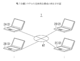
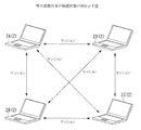
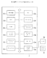
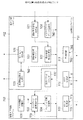
図1は電子会議システム1の全体的な構成の例を示す図、図2は端末装置2同士の接続形態の例を示す図、図3は端末装置2のハードウェア構成の例を示す図、図4は端末装置2の機能的構成の例を示す図である。   1 is a diagram illustrating an example of the overall configuration of the electronic conference system 1, FIG. 2 is a diagram illustrating an example of a connection form between terminal devices 2, and FIG. 3 is a diagram illustrating an example of a hardware configuration of the terminal device 2. FIG. 4 is a diagram illustrating an example of a functional configuration of the terminal device 2.

図1において、電子会議システム1は、互いに離れた場所にいるユーザ同士が会議を行うためのシステムである。   In FIG. 1, an electronic conference system 1 is a system for users in remote locations to hold a conference.

電子会議システム1は、複数台の端末装置2および通信回線NTなどを有する。端末装置2同士は通信回線NTを介して互いに接続可能である。通信回線NTとして、公衆回線、インターネット、またはLocal Area Network(LAN)回線などが用いられる。   The electronic conference system 1 includes a plurality of terminal devices 2 and a communication line NT. The terminal devices 2 can be connected to each other via the communication line NT. As the communication line NT, a public line, the Internet, a Local Area Network (LAN) line, or the like is used.

ユーザは、会議に参加するためには、原則として、自分の端末装置2を他のすべての参加者の端末装置2に接続させなければならない。したがって、参加者の端末装置2によって、図2に示すようなフルメッシュ型の接続形態が形成される。   In order to participate in the conference, the user must connect his / her terminal device 2 to the terminal devices 2 of all other participants in principle. Therefore, the participant's terminal device 2 forms a full mesh connection form as shown in FIG.

端末装置2は、図3に示すように、制御装置20a、Random Access Memory(RAM)20b、Read Only Memory(ROM)20c、ハードディスク20d、Network Interface Card(NIC)20e、キーボード20f、ポインティングデバイス20g、入出力インタフェース20h、グラフィックボード20i、ディスプレイ20j、サウンドボード20k、およびスピーカ20mなどを有する。   As shown in FIG. 3, the terminal device 2 includes a control device 20a, a random access memory (RAM) 20b, a read only memory (ROM) 20c, a hard disk 20d, a network interface card (NIC) 20e, a keyboard 20f, a pointing device 20g, It includes an input / output interface 20h, a graphic board 20i, a display 20j, a sound board 20k, a speaker 20m, and the like.

制御装置20aは、Central Processing Unit(CPU)またはMicro Processing Unit(MPU)などであって、RAM20bまたはROM20cに記憶されているプログラムを実行する。なお、制御装置20aがMPUである場合は、RAM20bおよびROM20cが制御装置20aに一体的に組み込まれていることがある。   The control device 20a is a central processing unit (CPU) or a micro processing unit (MPU), and executes a program stored in the RAM 20b or the ROM 20c. If the control device 20a is an MPU, the RAM 20b and the ROM 20c may be integrated into the control device 20a.

ROM20cまたはハードディスク20dには、オペレーティングシステムのほか、図4に示すSession Initiation Protocol(SIP)関連プログラムPG1、電子会議プログラムPG2、および障害回避プログラムPG3が記憶されている。これらのプログラムは、必要に応じてRAM20bにロードされ、制御装置20aによって実行される。   In addition to the operating system, the ROM 20c or the hard disk 20d stores a Session Initiation Protocol (SIP) related program PG1, an electronic conference program PG2, and a failure avoidance program PG3 shown in FIG. These programs are loaded into the RAM 20b as necessary and executed by the control device 20a.

NIC20eは、いわゆるLANカードであって、他の端末装置2と通信を行うために用いられる。   The NIC 20e is a so-called LAN card, and is used to communicate with another terminal device 2.

キーボード20fおよびポインティングデバイス20gは、ユーザがコマンドおよびデータを端末装置2に入力するための入力装置である。   The keyboard 20 f and the pointing device 20 g are input devices for a user to input commands and data to the terminal device 2.

入出力インタフェース20hは、ビデオカメラ3Vおよびマイク3Mを端末装置2に繋げるためのインタフェースである。入出力インタフェース20hとして、Universal Serial Bus(USB)またはInstitute of Electrical and Electronics Engineer(IEEE)1394などが用いられる。   The input / output interface 20h is an interface for connecting the video camera 3V and the microphone 3M to the terminal device 2. As the input / output interface 20h, Universal Serial Bus (USB) or Institute of Electrical and Electronics Engineer (IEEE) 1394 is used.

グラフィックボード20iは、制御装置20aからの指令に基づいて描画を行い、ディスプレイ20jへ映像(動画像)の信号を出力する。   The graphic board 20i performs drawing based on a command from the control device 20a, and outputs a video (moving image) signal to the display 20j.

ディスプレイ20jは、グラフィックボード20iから出力される信号に基づいて、会議に参加する者の映像などを表示する。   The display 20j displays a video of a person participating in the conference based on a signal output from the graphic board 20i.

サウンドボード20kは、制御装置20aからの指令に基づいて音声の信号を生成し、スピーカ20mへ出力する。   The sound board 20k generates a sound signal based on a command from the control device 20a and outputs the sound signal to the speaker 20m.

スピーカ20mは、サウンドボード20kから出力される信号に基づいて、会議に参加する者の音声を再生する。   The speaker 20m reproduces the voice of the person who participates in the conference based on the signal output from the sound board 20k.

端末装置2として、通信機能が備えられたパーソナルコンピュータまたはPersonal Digital Assistant(PDA)などの通信装置が用いられる。以下、各端末装置2を「端末装置2A」、「端末装置2B」、…と区別して記載することがある。   As the terminal device 2, a communication device such as a personal computer provided with a communication function or a personal digital assistant (PDA) is used. Hereinafter, the respective terminal devices 2 may be described separately as “terminal device 2A”, “terminal device 2B”,.

図4において、SIP関連プログラムPG1は、SIPに基づいて他の端末装置2と通信するための処理を行うプログラムである。SIP関連プログラムPG1によると、呼制御部511、Real-time Transport Protocol(RTP)制御部512、およびRTP Control Protocol(RTCP)制御部513などが実現される。   In FIG. 4, the SIP related program PG1 is a program that performs processing for communicating with other terminal devices 2 based on SIP. According to the SIP related program PG1, a call control unit 511, a Real-time Transport Protocol (RTP) control unit 512, an RTP Control Protocol (RTCP) control unit 513, and the like are realized.

電子会議プログラムPG2は、会議を招集したり端末装置2を会議に参加させたりするためのアプリケーションである。電子会議プログラムPG2によると、被招待者指定受付部521、電子会議形成処理部522、接続順管理テーブル523、マルチメディアデータ生成部524、会議画面表示処理部525、および音声出力処理部526などが実現される。   The electronic conference program PG2 is an application for calling a conference or causing the terminal device 2 to participate in the conference. According to the electronic conference program PG2, the invitee designation reception unit 521, the electronic conference formation processing unit 522, the connection order management table 523, the multimedia data generation unit 524, the conference screen display processing unit 525, the audio output processing unit 526, and the like. Realized.

障害回避プログラムPG3は、他の端末装置2とのセッションの障害を検知し当該他の端末装置2との通信の経路を変更するためのプログラムである。障害回避プログラムPG3によると、ロス率閾値記憶部531、受信パケットカウンタ532、ネットワーク品質判定部533、およびセッション切換処理部534などが実現される。   The failure avoidance program PG3 is a program for detecting a failure in a session with another terminal device 2 and changing a communication path with the other terminal device 2. According to the failure avoidance program PG3, a loss rate threshold storage unit 531, a received packet counter 532, a network quality determination unit 533, a session switching processing unit 534, and the like are realized.

以下、図4に示す各部の処理内容などを、4人のユーザUA、UB、UC、およびUDがそれぞれ4台の端末装置2A、2B、2C、および2Dを用いて会議を行う場合を例に、説明する。   In the following, the processing contents of each unit shown in FIG. 4 are taken as an example when four users UA, UB, UC, and UD hold a conference using four terminal devices 2A, 2B, 2C, and 2D, respectively. ,explain.

〔会議の開催のための処理〕
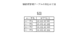
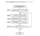
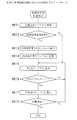
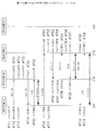
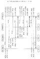
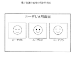
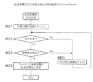
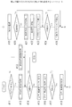
図5は接続順管理テーブル523の例を示す図、図6は主催者側接続処理の流れの例を説明するフローチャート、図7は被招待者側接続処理の流れの例を説明するフローチャート、図8および図9は電子会議の形成の処理の流れの例を示すシーケンス図、図10は電子会議の画面の例を示す図である。
[Process for holding the meeting]
5 is a diagram illustrating an example of the connection order management table 523, FIG. 6 is a flowchart illustrating an example of the flow of the organizer side connection process, and FIG. 7 is a flowchart illustrating an example of the flow of the invitee side connection process. 8 and FIG. 9 are sequence diagrams showing an example of the flow of processing for forming an electronic conference, and FIG. 10 is a diagram showing an example of a screen of the electronic conference.

SIP関連プログラムPG1の呼制御部511は、端末装置2自身と他の端末装置2との間の呼制御を行う。つまり、両装置間のセッションを確立しまたは切断する処理を行う。例えば、端末装置2Aの呼制御部511は、端末装置2Aと端末装置2B、2C、および2Dそれぞれとの間の呼制御を行う。   The call control unit 511 of the SIP related program PG1 performs call control between the terminal device 2 itself and another terminal device 2. That is, a process for establishing or disconnecting a session between both apparatuses is performed. For example, the call control unit 511 of the terminal device 2A performs call control between the terminal device 2A and each of the terminal devices 2B, 2C, and 2D.

RTP制御部512は、端末装置2自身のユーザの音声および映像のデータをRTPに基づいてパケット化し、他の端末装置2へ送信する処理を行う。以下、RTPに基づいて生成されたパケットを「RTPパケット6」と記載する。さらに、RTP制御部512は、他の端末装置2から送信されてきたRTPパケット6を受け付けて組み立てることによって、当該他の端末装置2のユーザの音声および映像のデータを再生成するための処理を行う。   The RTP control unit 512 performs processing of packetizing voice and video data of the user of the terminal device 2 itself based on RTP and transmitting the packet to other terminal devices 2. Hereinafter, a packet generated based on RTP is referred to as “RTP packet 6”. Further, the RTP control unit 512 receives the RTP packet 6 transmitted from the other terminal device 2 and assembles it to regenerate the voice and video data of the user of the other terminal device 2. Do.

RTCP制御部513は、RTCPに基づいて、RTPパケット6に関する監視を行いその結果の統計(図11、図12参照)を他の端末装置2へ通知する処理を行う。さらに、他の端末装置2からRTPパケット6に関する監視の結果の統計を受け取る処理を行う。   The RTCP control unit 513 performs processing for monitoring the RTP packet 6 based on the RTCP and notifying other terminal devices 2 of the statistics (see FIGS. 11 and 12) as a result. Furthermore, the process which receives the statistics of the monitoring result regarding the RTP packet 6 from the other terminal device 2 is performed.

電子会議プログラムPG2の被招待者指定受付部521は、会議の主催者であるユーザによる、会議へ招待する者(被招待者)の指定を受け付ける。具体的には、所定のコマンドが入力されると、入力用の画面がディスプレイ20jに表示されるように、グラフィックボード20iを制御する。そして、入力用の画面に入力された者を、被招待者として受け付ける。   The invitee designation accepting unit 521 of the electronic conference program PG2 accepts designation of a person (invitee) invited to the conference by the user who is the conference organizer. Specifically, when a predetermined command is input, the graphic board 20i is controlled such that an input screen is displayed on the display 20j. Then, a person input on the input screen is accepted as an invitee.

例えば、ユーザUAが主催者である場合は、ユーザUAは、入力用の画面に、ユーザUB、UC、およびUDを指定する。端末装置2Aの被招待者指定受付部521は、ユーザUB、UC、およびUDを被招待者として受け付ける。   For example, when the user UA is the organizer, the user UA specifies the users UB, UC, and UD on the input screen. The invitee designation accepting unit 521 of the terminal device 2A accepts the users UB, UC, and UD as invitees.

電子会議形成処理部522は、端末装置2自身と他の端末装置2とのセッションの確立し会議(電子会議)を形成するための処理を行う。   The electronic conference formation processing unit 522 performs processing for establishing a session between the terminal device 2 itself and another terminal device 2 and forming a conference (electronic conference).

接続順管理テーブル523には、図5のように、会議を形成する端末装置2の所有者およびIPアドレスが、会議に加わった順に示されている。会議が終了するごとに、接続順管理テーブル523は、リセットされ、どの端末装置2をも示さなくなる。   In the connection order management table 523, as shown in FIG. 5, the owners and IP addresses of the terminal devices 2 forming the conference are shown in the order in which the conference was added. Each time the conference ends, the connection order management table 523 is reset and no terminal device 2 is shown.

そのほか、どのユーザ名のユーザがどのIPアドレスの端末装置2を使用するのかを示すテーブルが、端末装置2に用意されている。   In addition, a table indicating which IP address of the terminal device 2 is used by the user with which user name is prepared in the terminal device 2.

ここで、ユーザUAが主催者でありユーザUB、UC、およびUDが被招待者である場合を例に、各端末装置2の電子会議形成処理部522の処理内容および各端末装置2の接続順管理テーブル523の変化について説明する。   Here, taking as an example the case where the user UA is the organizer and the users UB, UC, and UD are invitees, the processing contents of the electronic conference formation processing unit 522 of each terminal device 2 and the connection order of each terminal device 2 A change in the management table 523 will be described.

ユーザUAの端末装置2(2A)の電子会議形成処理部522は、図6のフローチャートに示す手順で処理を実行する。   The electronic conference formation processing unit 522 of the terminal device 2 (2A) of the user UA executes processing according to the procedure shown in the flowchart of FIG.

ユーザUAがユーザUB、UC、およびUDの順に被招待者を指定したとする。すると、電子会議形成処理部522は、自らの接続順管理テーブル523に、主催者つまりユーザUAのユーザ名および端末装置2A自身のIPアドレスを示すレコードを追加する(#601)。さらに、電子会議形成処理部522は、ユーザUAが指定した順に、各被参加者の端末装置2に対して、次の処理を行う。   It is assumed that the user UA designates the invitee in the order of the users UB, UC, and UD. Then, the electronic conference formation processing unit 522 adds a record indicating the organizer, that is, the user name of the user UA and the IP address of the terminal device 2A itself to the connection order management table 523 (# 601). Furthermore, the electronic conference formation processing unit 522 performs the following processing on the terminal device 2 of each participant in the order specified by the user UA.

電子会議形成処理部522は、1番目に指定されたユーザUBの端末装置2(端末装置2B)へINVITEメッセージを送信し(#602)、端末装置2A自身と端末装置2Bとのセッションの確立を図る(#603)。   The electronic conference formation processing unit 522 transmits an INVITE message to the terminal device 2 (terminal device 2B) of the first designated user UB (# 602), and establishes a session between the terminal device 2A itself and the terminal device 2B. (# 603).

セッションの確立の処理と並行してまたは前後して、電子会議形成処理部522は、ユーザUBのユーザ名および端末装置2BのIPアドレスを示すレコードを自らの接続順管理テーブル523の最後尾に追加する(#604)。   In parallel with or before or after the session establishment process, the electronic conference formation processing unit 522 adds a record indicating the user name of the user UB and the IP address of the terminal device 2B to the end of its connection order management table 523. (# 604).

電子会議形成処理部522は、残りの被参加者の端末装置2に対しても、ユーザUAが指定した順に同様の処理を行う(#602〜#604)。   The electronic conference formation processing unit 522 performs the same processing on the remaining participant's terminal devices 2 in the order designated by the user UA (# 602 to # 604).

なお、電子会議形成処理部522は、INVITEメッセージを送信する際に、N番目の端末装置2に対して、N番目までの被招待者の端末装置2のIPアドレスを通知する。   In addition, when transmitting the INVITE message, the electronic conference formation processing unit 522 notifies the N-th terminal device 2 of the IP addresses of the terminal devices 2 of the invitees up to the Nth.

また、INVITEメッセージの送信およびセッションの確立の処理は、SIP関連プログラムPG1の呼制御部511と連携して行われる。後述する各メッセージの送受信およびセッションの切断などの処理も、呼制御部511と連携して行われる。   The INVITE message transmission and session establishment processing are performed in cooperation with the call control unit 511 of the SIP related program PG1. Processing such as transmission / reception of each message and disconnection of a session to be described later is also performed in cooperation with the call control unit 511.

一方、被招待者の端末装置2(2B、2C、2D)において、電子会議形成処理部522は、端末装置2AからINVITEメッセージを受信すると、図7のフローチャートに示す手順で処理を実行する。   On the other hand, in the invitee's terminal device 2 (2B, 2C, 2D), when the electronic conference formation processing unit 522 receives the INVITE message from the terminal device 2A, the electronic conference formation processing unit 522 executes processing in accordance with the procedure shown in the flowchart of FIG.

電子会議形成処理部522は、主催者のユーザUAの端末装置2(2A)を自らの接続順管理テーブル523の最後尾に追加する(#611)。   The electronic conference formation processing unit 522 adds the terminal device 2 (2A) of the organizer user UA to the end of its connection order management table 523 (# 611).

電子会議形成処理部522は、端末装置2Aから通知された被招待者の端末装置2の中に、他の端末装置2が含まれていない場合は(#612でNo)、自らの所有者であるユーザのユーザ名および自らのIPアドレスを示すレコードを自らの接続順管理テーブル523の最後尾に追加する(#615)。本例では、端末装置2Bの電子会議形成処理部522が、この場合に該当する。   If the other terminal device 2 is not included in the invitee's terminal device 2 notified from the terminal device 2A (No in # 612), the electronic conference formation processing unit 522 is the own owner. A record indicating the user name of one user and his / her own IP address is added to the end of his / her connection order management table 523 (# 615). In this example, the electronic conference formation processing unit 522 of the terminal device 2B corresponds to this case.

一方、電子会議形成処理部522は、端末装置2Aから通知された被招待者の端末装置2の中に、他の端末装置2が含まれている場合は(#612でYes)、若い他の端末装置2から順に、セッションの確立を図るとともに(#613)、当該他の端末装置2のユーザのユーザ名および自らのIPアドレスを示すレコードを自らの接続順管理テーブル523の最後尾に追加する(#614)。そして、自らの所有者であるユーザのユーザ名および自らのIPアドレスを示すレコードを自らの接続順管理テーブル523の最後尾に追加する(#615)。   On the other hand, when the other terminal device 2 is included in the invitee's terminal device 2 notified from the terminal device 2A (Yes in # 612), the electronic conference formation processing unit 522 In order from the terminal device 2 in order to establish a session (# 613), a record indicating the user name of the user of the other terminal device 2 and its own IP address is added to the end of its own connection order management table 523. (# 614). Then, a record indicating the user name of the user who is the owner and the IP address of the user is added to the tail of the connection order management table 523 (# 615).

その後、会議が開始するなどの所定のタイミングが訪れるまで、電子会議形成処理部522は、他の被招待者の端末装置2からINVITEメッセージを受信するごとに(#616)、当該他の被招待者のユーザ名および当該他の被招待者の端末装置2のIPアドレスを示すレコードを自らの接続順管理テーブル523の最後尾に追加する(#617)。   Thereafter, the electronic conference formation processing unit 522 receives the INVITE message from the other invitee's terminal device 2 (# 616) until a predetermined timing such as the start of the conference arrives (# 616). A record indicating the user's user name and the IP address of the other invitee's terminal device 2 is added to the end of its own connection order management table 523 (# 617).

各端末装置2における上記の処理を、図8および図9のシーケンス図を参照しながら、さらに詳細に説明する。   The above processing in each terminal device 2 will be described in more detail with reference to the sequence diagrams of FIGS. 8 and 9.

ユーザUAがユーザUB、UC、およびUDの順に被招待者を指定すると、端末装置2Aは、ユーザUAのユーザ名および端末装置2AのIPアドレスを示すレコードを自らの接続順管理テーブル523に追加する(図8の#711)。   When the user UA designates the invitee in the order of the users UB, UC, and UD, the terminal device 2A adds a record indicating the user name of the user UA and the IP address of the terminal device 2A to the own connection order management table 523. (# 711 in FIG. 8).

さらに、端末装置2Aは、1番目に指定されたユーザUBの端末装置2つまり端末装置2BへINVITEメッセージを送信し(#712)、ユーザUBのユーザ名および端末装置2BのIPアドレスを示すレコードを自らの接続順管理テーブル523に追加する(#713)。なお、端末装置2Aは、INVITEメッセージを送信する際に、被招待者の端末装置2のIPアドレスとして、端末装置2BのIPアドレスのみを端末装置2Bへ通知する。   Further, the terminal device 2A transmits an INVITE message to the terminal device 2 of the first designated user UB, that is, the terminal device 2B (# 712), and a record indicating the user name of the user UB and the IP address of the terminal device 2B is sent. It adds to its own connection order management table 523 (# 713). When transmitting the INVITE message, the terminal device 2A notifies only the IP address of the terminal device 2B to the terminal device 2B as the IP address of the invitee terminal device 2.

端末装置2Bは、端末装置2AからINVITEメッセージを受信すると(#731)、主催者つまりユーザUAのユーザ名および端末装置2AのIPアドレスを示すレコードを自らの接続順管理テーブル523に追加する(#732)。   When the terminal device 2B receives the INVITE message from the terminal device 2A (# 731), the terminal device 2B adds a record indicating the organizer, that is, the user name of the user UA and the IP address of the terminal device 2A to the own connection order management table 523 (#). 732).

端末装置2Bは、被招待者の端末装置2のIPアドレスとして、端末装置2B自らのIPアドレスしか通知されていないので、他の被招待者の端末装置2とのセッションの確立を実行することなく、ユーザUBのユーザ名および端末装置2B自身のIPアドレスを示すレコードを自らの接続順管理テーブル523に追加する(#733)。そして、OKメッセージを端末装置2Aへ返信する(#734)。   Since the terminal device 2B is notified of only the IP address of the terminal device 2B itself as the IP address of the invitee terminal device 2, the terminal device 2B does not establish a session with the other invitee terminal device 2. Then, a record indicating the user name of the user UB and the IP address of the terminal device 2B itself is added to the own connection order management table 523 (# 733). Then, an OK message is returned to the terminal device 2A (# 734).

端末装置2Aは、ステップ#712で送信したINVITEメッセージに対するOKメッセージを端末装置2Bから受信すると(#714)、ACKメッセージを端末装置2Bへ返信する(#715)。そして、端末装置2BがACKメッセージを受信すると(#735)、端末装置2A、2Bは、両者間のセッションを確立する。   When the terminal device 2A receives an OK message for the INVITE message transmitted in step # 712 from the terminal device 2B (# 714), it returns an ACK message to the terminal device 2B (# 715). When the terminal device 2B receives the ACK message (# 735), the terminal devices 2A and 2B establish a session between them.

端末装置2Aは、2番目に指定されたユーザUCの端末装置2つまり端末装置2CへINVITEメッセージを送信し(#716)、ユーザUCのユーザ名および端末装置2CのIPアドレスを示すレコードを自らの接続順管理テーブル523に追加する(#717)。なお、端末装置2Aは、INVITEメッセージを送信する際に、被招待者の端末装置2のIPアドレスとして、端末装置2Bおよび端末装置2CそれぞれのIPアドレスを端末装置2Cへ通知する。   The terminal device 2A transmits an INVITE message to the terminal device 2 of the second designated user UC, that is, the terminal device 2C (# 716), and records a record indicating the user name of the user UC and the IP address of the terminal device 2C. This is added to the connection order management table 523 (# 717). When transmitting the INVITE message, the terminal device 2A notifies the terminal device 2C of the IP addresses of the terminal device 2B and the terminal device 2C as the IP address of the invitee terminal device 2, respectively.

端末装置2Cは、端末装置2AからINVITEメッセージを受信すると(#751)、主催者つまりユーザUAのユーザ名および端末装置2AのIPアドレスを示すレコードを自らの接続順管理テーブル523に追加する(#752)。   When the terminal device 2C receives the INVITE message from the terminal device 2A (# 751), the terminal device 2C adds a record indicating the organizer, that is, the user name of the user UA and the IP address of the terminal device 2A to the own connection order management table 523 (#). 752).

端末装置2Cは、被招待者の端末装置2のIPアドレスとして、端末装置2C自らのIPアドレスだけでなく端末装置2BのIPアドレスをも通知される。そこで、端末装置2Cは、端末装置2Bとのセッションの確立を図る。   The terminal apparatus 2C is notified of not only the IP address of the terminal apparatus 2C itself but also the IP address of the terminal apparatus 2B as the IP address of the invitee terminal apparatus 2. Accordingly, the terminal device 2C establishes a session with the terminal device 2B.

すなわち、端末装置2Cは、端末装置2BへINVITEメッセージを送信する(#753)。   That is, the terminal device 2C transmits an INVITE message to the terminal device 2B (# 753).

端末装置2Bは、INVITEメッセージを受信すると(#736)、ユーザUCのユーザ名および端末装置2CのIPアドレスを示すレコード(つまり、INVITEメッセージの送信元のレコード)を自らの接続順管理テーブル523の最後尾に追加する(#737)。そして、端末装置2Bは、端末装置2CへOKメッセージを返信する(#738)。   When the terminal device 2B receives the INVITE message (# 736), it records a record indicating the user name of the user UC and the IP address of the terminal device 2C (that is, the record of the source of the INVITE message) in its own connection order management table 523. It is added at the end (# 737). Then, the terminal device 2B returns an OK message to the terminal device 2C (# 738).

端末装置2Cは、OKメッセージを受信すると(#755)、ユーザUCのユーザ名および端末装置2C自身のIPアドレスを示すレコードを自らの接続順管理テーブル523の最後尾に追加する(#756)。そして、ACKメッセージを端末装置2Bへ返信し(#757)、OKメッセージを端末装置2Aへ返信する(#758)。   When the terminal device 2C receives the OK message (# 755), it adds a record indicating the user name of the user UC and the IP address of the terminal device 2C itself to the end of its own connection order management table 523 (# 756). Then, an ACK message is returned to the terminal device 2B (# 757), and an OK message is returned to the terminal device 2A (# 758).

端末装置2Cが端末装置2BからのACKメッセージを受信すると(#739)、端末装置2Bおよび2Cは、両者間のセッションを確立する。   When the terminal device 2C receives the ACK message from the terminal device 2B (# 739), the terminal devices 2B and 2C establish a session between them.

端末装置2Aは、ステップ#716で送信したINVITEメッセージに対するOKメッセージを端末装置2Cから受信すると(#718)、ACKメッセージを端末装置2Cへ返信する(#719)。そして、端末装置2CがACKメッセージを受信すると(#759)、端末装置2A、2Cは、両者間のセッションを確立する。   When the terminal device 2A receives an OK message for the INVITE message transmitted in step # 716 from the terminal device 2C (# 718), it returns an ACK message to the terminal device 2C (# 719). When the terminal device 2C receives the ACK message (# 759), the terminal devices 2A and 2C establish a session between them.

これにより、端末装置2A、2B、および2Cの3者間の通信が可能になる。つまり、ユーザUA、UB、およびUCによる会議が可能になる。   Thereby, communication between the three parties of the terminal devices 2A, 2B, and 2C becomes possible. That is, a conference by the users UA, UB, and UC is possible.

端末装置2Aは、3番目に指定されたユーザUDの端末装置2つまり端末装置2DへINVITEメッセージを送信し(図9の#720)、ユーザUDのユーザ名および端末装置2DのIPアドレスを示すレコードを自らの接続順管理テーブル523に追加する(#721)。なお、端末装置2Aは、INVITEメッセージを送信する際に、被招待者の端末装置2のIPアドレスとして、端末装置2B、2C、および2DそれぞれのIPアドレスを端末装置2Dへ通知する。   The terminal device 2A transmits an INVITE message to the terminal device 2 of the third designated user UD, that is, the terminal device 2D (# 720 in FIG. 9), and a record indicating the user name of the user UD and the IP address of the terminal device 2D Is added to its own connection order management table 523 (# 721). When transmitting the INVITE message, the terminal device 2A notifies the terminal device 2D of the IP address of each of the terminal devices 2B, 2C, and 2D as the IP address of the invitee terminal device 2.

端末装置2Dは、端末装置2AからINVITEメッセージを受信すると(#771)、主催者つまりユーザUAのユーザ名および端末装置2AのIPアドレスを示すレコードを自らの接続順管理テーブル523に追加する(#772)。   When the terminal device 2D receives the INVITE message from the terminal device 2A (# 771), the terminal device 2D adds a record indicating the organizer, that is, the user name of the user UA and the IP address of the terminal device 2A to the own connection order management table 523 (#). 772).

端末装置2Dは、被招待者の端末装置2のIPアドレスとして、端末装置2D自らのIPアドレスだけでなく端末装置2Bおよび2CそれぞれのIPアドレスをも通知される。そこで、端末装置2Dは、端末装置2Bおよび2Cそれぞれとのセッションの確立を図る。   The terminal device 2D is notified of not only the IP address of the terminal device 2D itself but also the IP addresses of the terminal devices 2B and 2C as the IP address of the invitee terminal device 2. Therefore, the terminal device 2D attempts to establish a session with each of the terminal devices 2B and 2C.

すなわち、端末装置2Dは、まず、端末装置2Bとのセッションの確立のために、端末装置2Cが実行した図8のステップ#753〜#757と同様の処理を行う(#773〜#776)。ただし、ここでは、ユーザUBのユーザ名および端末装置2BのIPアドレスを示すレコードは追加するが(#774)、ユーザUDのユーザ名および端末装置2D自らのIPアドレスを示すレコードは未だ追加しない。   That is, the terminal device 2D first performs the same processing as steps # 753 to # 757 of FIG. 8 executed by the terminal device 2C in order to establish a session with the terminal device 2B (# 773 to # 776). However, although a record indicating the user name of the user UB and the IP address of the terminal device 2B is added here (# 774), a record indicating the user name of the user UD and the IP address of the terminal device 2D itself is not yet added.

端末装置2Bは、ステップ#736〜#739と同様の処理を、端末装置2Dを相手に行う(#740〜#743)。この際に、ユーザUDのユーザ名および端末装置2DのIPアドレスを示すレコードを追加する(#741)。   The terminal device 2B performs the same processing as steps # 736 to # 739 on the terminal device 2D (# 740 to # 743). At this time, a record indicating the user name of the user UD and the IP address of the terminal device 2D is added (# 741).

端末装置2Dは、次に、端末装置2Cとのセッションの確立のために、図8のステップ#753〜#757と同様の処理を行う(#777〜#781)。この際に、ユーザUCのユーザ名および端末装置2CのIPアドレスを示すレコードを追加し(#778)、さらに、ユーザUDのユーザ名および端末装置2D自らのIPアドレスを示すレコードを追加する(#780)。   Next, the terminal device 2D performs the same processing as steps # 753 to # 757 in FIG. 8 to establish a session with the terminal device 2C (# 777 to # 781). At this time, a record indicating the user name of the user UC and the IP address of the terminal device 2C is added (# 778), and a record indicating the user name of the user UD and the IP address of the terminal device 2D itself is added (#). 780).

端末装置2Cは、端末装置2Bのステップ#736〜#739と同様の処理を、端末装置2Dを相手に行う(#760〜#763)。この際に、ユーザUDのユーザ名および端末装置2DのIPアドレスを示すレコードを追加する(#741)。   The terminal device 2C performs the same processing as steps # 736 to # 739 of the terminal device 2B on the other side of the terminal device 2D (# 760 to # 763). At this time, a record indicating the user name of the user UD and the IP address of the terminal device 2D is added (# 741).

端末装置2Dは、端末装置2Bおよび2Cそれぞれとのセッションが確立できたら、OKメッセージを端末装置2Aへ返信する(#782)。   When the terminal device 2D has established a session with each of the terminal devices 2B and 2C, it returns an OK message to the terminal device 2A (# 782).

端末装置2Aは、ステップ#720で送信したINVITEメッセージに対するOKメッセージを端末装置2Dから受信すると(#722)、ACKメッセージを端末装置2Dへ返信する(#723)。そして、端末装置2DがACKメッセージを受信すると(#783)、端末装置2A、2Dは、両者間のセッションを確立する。   When the terminal device 2A receives an OK message for the INVITE message transmitted in step # 720 from the terminal device 2D (# 722), it returns an ACK message to the terminal device 2D (# 723). When the terminal device 2D receives the ACK message (# 783), the terminal devices 2A and 2D establish a session between them.

これにより、端末装置2A、2B、2C、および2Dの4者間の通信が可能になる。つまり、ユーザUA、UB、UC、およびUDによる会議が可能になる。   Thereby, communication between four persons of terminal device 2A, 2B, 2C, and 2D is attained. That is, a conference by the users UA, UB, UC, and UD becomes possible.

図4に戻って、電子会議プログラムPG2のマルチメディアデータ生成部524は、会議の開催中、ビデオカメラ3Vによって撮影されまたはマイク3Mによって録音された、端末装置2自身のユーザの動画像および音声のマルチメディアデータ7MDを生成する。   Returning to FIG. 4, the multimedia data generation unit 524 of the electronic conference program PG2 captures the moving image and audio of the user of the terminal device 2 itself, which is captured by the video camera 3V or recorded by the microphone 3M during the conference. Multimedia data 7MD is generated.

マルチメディアデータ7MDは、SIP関連プログラムPG1のRTP制御部512によって分割されRTPパケット6に変換される。そして、他の端末装置2へ送信される。例えば、端末装置2Aにおいては、ユーザUAのマルチメディアデータ7MDがRTPパケット6に変換され、端末装置2B、2C、および2Dへ送信される。   The multimedia data 7MD is divided by the RTP control unit 512 of the SIP related program PG1 and converted into the RTP packet 6. Then, it is transmitted to another terminal device 2. For example, in the terminal device 2A, the multimedia data 7MD of the user UA is converted into the RTP packet 6 and transmitted to the terminal devices 2B, 2C, and 2D.

また、前に述べた通り、RTP制御部512は、他の端末装置2から送信されてきたRTPパケット6を組み立て、マルチメディアデータ7MDを再生成する。例えば、端末装置2Aにおいては、端末装置2Bから送信されてきたRTPパケット6を組み立てて、ユーザUBのマルチメディアデータ7MDを再生成する。端末装置2Cから送信されてきたRTPパケット6を組み立てて、ユーザUCのマルチメディアデータ7MDを再生成する。さらに、端末装置2Dから送信されてきたRTPパケット6を組み立てて、ユーザUDのマルチメディアデータ7MDを再生成する。   Further, as described above, the RTP control unit 512 assembles the RTP packet 6 transmitted from the other terminal apparatus 2 and regenerates the multimedia data 7MD. For example, in the terminal device 2A, the RTP packet 6 transmitted from the terminal device 2B is assembled, and the multimedia data 7MD of the user UB is regenerated. The RTP packet 6 transmitted from the terminal device 2C is assembled, and the multimedia data 7MD of the user UC is regenerated. Furthermore, the RTP packet 6 transmitted from the terminal device 2D is assembled, and the multimedia data 7MD of the user UD is regenerated.

会議画面表示処理部525は、再生成されたマルチメディアデータ7MDを用いて他の端末装置2のユーザの動画像が図10のようにディスプレイ20jに表示されるように、グラフィックボード20iを制御する。   The conference screen display processing unit 525 controls the graphic board 20i using the regenerated multimedia data 7MD so that the moving image of the user of the other terminal device 2 is displayed on the display 20j as shown in FIG. .

音声出力処理部526は、再生されたマルチメディアデータ7MDを用いて他の端末装置2のユーザの音声がスピーカ20mから出力されるように、サウンドボード20kを制御する。   The sound output processing unit 526 controls the sound board 20k so that the sound of the user of the other terminal device 2 is output from the speaker 20m using the reproduced multimedia data 7MD.

〔セッションの障害を検知し回避するための処理〕
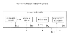
図11は障害の発生を検知する処理の手順の第一の例を説明するための図、図12は障害の発生を検知する処理の手順の第一の例を説明するための図、図13はセッション切換処理部534の構成の例を示す図である。
[Processes to detect and avoid session failures]
FIG. 11 is a diagram for explaining a first example of a processing procedure for detecting the occurrence of a failure, FIG. 12 is a diagram for explaining a first example of a processing procedure for detecting the occurrence of a failure, and FIG. FIG. 4 is a diagram illustrating an example of a configuration of a session switching processing unit 534.

障害回避プログラムPG3のロス率閾値記憶部531は、セッションに障害が発生しているか否かを判定する基準であるロス率閾値αを記憶する。   The loss rate threshold storage unit 531 of the failure avoidance program PG3 stores a loss rate threshold α that is a reference for determining whether or not a failure has occurred in the session.

受信パケットカウンタ532は、端末装置2自身が使用するセッションごとに、相手方から受信したRTPパケット6の個数Krをカウントする。この際に、個数Krがどの時点のものであるか、つまり、タイムスタンプを、記録しておく。   The reception packet counter 532 counts the number Kr of RTP packets 6 received from the other party for each session used by the terminal device 2 itself. At this time, the time stamp of the number Kr, that is, the time stamp is recorded.

ネットワーク品質判定部533は、セッションの品質の良否を、SIP関連プログラムPG1のRTP制御部512が現実に取り扱ったRTPパケット6の個数とRTCP制御部513によって得られた統計の情報に基づいて、判定する。以下、端末装置2Aが端末装置2Bとのセッションの障害の有無を判定する場合を例に、ネットワーク品質判定部533の処理を、図11を参照しながら説明する。   The network quality determination unit 533 determines the quality of the session based on the number of RTP packets 6 actually handled by the RTP control unit 512 of the SIP related program PG1 and the statistical information obtained by the RTCP control unit 513. To do. Hereinafter, the processing of the network quality determination unit 533 will be described with reference to FIG. 11, taking as an example the case where the terminal device 2 </ b> A determines whether or not there is a session failure with the terminal device 2 </ b> B.

端末装置2Aのネットワーク品質判定部533は、RTCP制御部513が統計の情報(以下、「統計情報7TD」と記載する。)を端末装置2Bから受信すると、その統計情報7TDから、タイムスタンプに示される時点の、端末装置2Bから端末装置2Aへ送信されたRTPパケット6の個数Ksをチェックする。さらに、同じ時点の、端末装置2A自身が端末装置2Bから受信したRTPパケット6の個数Krをチェックする。端末装置2Bから端末装置2Aへ発信されたRTPパケット6に対するロスしたRTPパケット6個数の割合(例えば、5%。以下、「パケットロス率β」と記載する。)を、次の(1)式より算出する。
β={(Ks−Kr)/Ks}×100[%] …… (1)

そして、ネットワーク品質判定部533は、βがαを超えていれば、端末装置2Bとのセッションに障害が発生していると、判定する。
When the RTCP control unit 513 receives statistical information (hereinafter referred to as “statistical information 7TD”) from the terminal apparatus 2B, the network quality determination unit 533 of the terminal device 2A indicates the time stamp from the statistical information 7TD. At this time, the number Ks of RTP packets 6 transmitted from the terminal device 2B to the terminal device 2A is checked. Further, at the same time, the terminal device 2A itself checks the number Kr of RTP packets 6 received from the terminal device 2B. The ratio of the number of lost RTP packets 6 to the RTP packet 6 transmitted from the terminal device 2B to the terminal device 2A (for example, 5%, hereinafter referred to as “packet loss rate β”) is expressed by the following equation (1). Calculate from
β = {(Ks−Kr) / Ks} × 100 [%] (1)

Then, if β exceeds α, the network quality determination unit 533 determines that a failure has occurred in the session with the terminal device 2B.

または、ネットワーク品質判定部533は、図12に示すような方法でセッションの障害の有無を判定することも、できる。   Alternatively, the network quality determination unit 533 can also determine the presence or absence of a session failure by a method as shown in FIG.

例えば、端末装置2Aのネットワーク品質判定部533は、ある期間における端末装置2Bとのセッションの障害の有無を判別するために、この期間の最初に端末装置2Bから受信した統計情報7TDに示される個数Ks1と最後に端末装置2Bから受信した統計情報7TDに示される個数Ks2との差である個数Ks3(個数Ks2−個数Ks1)を求める。さらに、同じ期間に端末装置2Bから受信したRTPパケット6の個数Kr3をチェックする。端末装置2Bから端末装置2Aへ発信されたRTPパケット6に対するロスしたRTPパケット6の個数の割合(以下、「パケットロス率β’」と記載する。)を、次の(2)式より算出する。
β’={(Ks3−Kr3)/Ks3}×100[%] …… (2)

そして、ネットワーク品質判定部533は、β’がαを超えていれば、端末装置2Bとのセッションに障害が発生していると、判定する。このようにして、ネットワーク品質判定部533によってセッションの障害が検知される。
For example, the network quality determination unit 533 of the terminal device 2A counts the number indicated in the statistical information 7TD received from the terminal device 2B at the beginning of this period in order to determine whether there is a failure in the session with the terminal device 2B in a certain period. A number Ks3 (number Ks2−number Ks1), which is a difference between Ks1 and the number Ks2 indicated in the statistical information 7TD last received from the terminal device 2B, is obtained. Further, the number Kr3 of RTP packets 6 received from the terminal device 2B during the same period is checked. The ratio of the number of lost RTP packets 6 to the RTP packet 6 transmitted from the terminal device 2B to the terminal device 2A (hereinafter referred to as “packet loss rate β ′”) is calculated from the following equation (2). .
β ′ = {(Ks3-Kr3) / Ks3} × 100 [%] (2)

Then, the network quality determination unit 533 determines that a failure has occurred in the session with the terminal device 2B if β ′ exceeds α. In this way, a session failure is detected by the network quality determination unit 533.

図4に戻って、セッション切換処理部534は、セッションに障害が発生していると判定された場合に、そのセッションによって繋がれている2台の端末装置2間の通信を、別の経路を経由して行えるように、処理を行う。セッション切換処理部534は、図13に示すように、転送依頼先決定部551、転送依頼要求部552、転送セッション確立制御部553、および転送処理部554を有する。転送依頼先決定部551および転送依頼要求部552は、自らのセッションの障害が検知された場合にそのセッションの相手からのデータを他の端末装置2から転送してもらうための処理を行う。転送セッション確立制御部553および転送処理部554は、障害が発生したセッションを有する他の端末装置2に対してデータを転送するための処理を行う。   Returning to FIG. 4, when it is determined that a failure has occurred in the session, the session switching processing unit 534 performs communication between the two terminal devices 2 connected by the session through another route. Process so that it can be done via. The session switching processing unit 534 includes a transfer request destination determination unit 551, a transfer request request unit 552, a transfer session establishment control unit 553, and a transfer processing unit 554, as shown in FIG. The transfer request destination determination unit 551 and the transfer request request unit 552 perform processing for receiving data from the other party of the session device 2 when a failure of its own session is detected. The transfer session establishment control unit 553 and the transfer processing unit 554 perform processing for transferring data to another terminal device 2 having a session in which a failure has occurred.

以下、セッション切換処理部534の各部の処理内容を、端末装置2B、2C間のセッションに障害が発生した場合を例に、説明する。   Hereinafter, the processing contents of each unit of the session switching processing unit 534 will be described by taking as an example a case where a failure occurs in the session between the terminal devices 2B and 2C.

(I) 端末装置2Bが端末装置2Cよりも先にセッションの障害を検知した場合
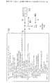
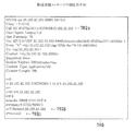
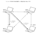
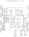
図14は転送依頼先決定処理の流れの例を説明するフローチャート、図15は転送依頼メッセージ7RQの例を示す図、図16はセッションの変更後の端末装置2同士の接続形態の例を示す図、図17はセッションの変更の処理の流れの第一の例を示すシーケンス図、図18はINVITEメッセージの例を示す図、図19および図20はOKメッセージの例を示す図である。
(I) When Terminal Device 2B Detects Session Failure Prior to Terminal Device 2C FIG. 14 is a flowchart illustrating an example of a flow of transfer request destination determination processing, and FIG. 15 is a diagram illustrating an example of a transfer request message 7RQ. 16 is a diagram showing an example of a connection form between terminal devices 2 after a session change, FIG. 17 is a sequence diagram showing a first example of a flow of session change processing, and FIG. 18 is an example of an INVITE message FIGS. 19 and 20 are diagrams showing examples of OK messages.

端末装置2Bにおいて、端末装置2Cとのセッションの障害が検知されると、転送依頼先決定部551は、端末装置2Cのユーザ(ユーザUC)のデータをどの端末装置2から転送してもらうのかを、図14に示す手順で決定する。   When a failure in a session with the terminal device 2C is detected in the terminal device 2B, the transfer request destination determination unit 551 determines from which terminal device 2 the data of the user (user UC) of the terminal device 2C is transferred. This is determined by the procedure shown in FIG.

端末装置2Bの転送依頼先決定部551は、自らの接続順管理テーブル523(図5参照)の先頭のレコードをチェックする(図14の#621)。   The transfer request destination determination unit 551 of the terminal device 2B checks the top record of its own connection order management table 523 (see FIG. 5) (# 621 in FIG. 14).

そのレコードに端末装置2B自身のIPアドレスおよび障害が発生したセッションの相手(本例では、端末装置2C)のIPアドレスのいずれも示されていない場合は(#622でNoかつ#623でNo)、チェックしたIPアドレスを有する端末装置2を、転送の依頼先に決定する(#625)。   If neither the IP address of the terminal device 2B itself nor the IP address of the other party (in this example, the terminal device 2C) in the failure is indicated in the record (No in # 622 and No in # 623) The terminal device 2 having the checked IP address is determined as the transfer request destination (# 625).

一方、端末装置2Bまたは2CいずれかのIPアドレスが示されている場合は(#622でYesまたは#623でYes)、次のレコードをチェックする(#624)。そして、いずれのIPアドレスも示されていない場合は(#622でNoかつ#623でNo)、チェックしたIPアドレスの端末装置2を、転送の依頼先に決定する(#625)。いずれかのIPアドレスが示される場合は(#623でYesまたは#624でYes)、以下、同様に、その次のレコードのIPアドレスをチェックし(#623)、それが端末装置2B、2CいずれのIPアドレスとも一致しなければ、それを有する端末装置2を、転送の依頼先に決定する(#625)。   On the other hand, if the IP address of either the terminal device 2B or 2C is indicated (Yes in # 622 or Yes in # 623), the next record is checked (# 624). If no IP address is indicated (No in # 622 and No in # 623), the terminal device 2 having the checked IP address is determined as a transfer request destination (# 625). When one of the IP addresses is indicated (Yes in # 623 or Yes in # 624), the IP address of the next record is checked in the same manner (# 623), which is the terminal device 2B or 2C. If the IP address does not match, the terminal device 2 having the IP address is determined as the transfer request destination (# 625).

つまり、転送依頼先決定部551は、接続順管理テーブル523の中の、端末装置2BのIPアドレスも端末装置2CのIPアドレスも示されない最上位のレコードを検索し、そのレコードに示されるIPアドレスを有する端末装置2を、転送の依頼先に決定する。   That is, the transfer request destination determination unit 551 searches the connection order management table 523 for the highest-order record in which neither the IP address of the terminal device 2B nor the IP address of the terminal device 2C is indicated, and the IP address indicated in the record Is determined as a transfer request destination.

端末装置2Bの転送依頼要求部552は、転送依頼先決定部551によって決定された転送先へ転送依頼メッセージ7RQを送信する。   The transfer request request unit 552 of the terminal device 2B transmits the transfer request message 7RQ to the transfer destination determined by the transfer request destination determination unit 551.

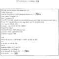
転送依頼メッセージ7RQは、データの転送を依頼(要求)するメッセージである。図15に示すように、転送依頼メッセージ7RQには、呼識別子情報7RQa、供給元アドレス情報7RQb、およびデータ取扱情報7RQcが含まれている。   The transfer request message 7RQ is a message for requesting (requesting) data transfer. As shown in FIG. 15, the transfer request message 7RQ includes call identifier information 7RQa, source address information 7RQb, and data handling information 7RQc.

呼識別子情報7RQaは、この転送依頼メッセージ7RQを識別するためのCall−ID(Identification)を示す。Call−IDの「@」の後ろは、この転送依頼メッセージ7RQの送信側つまり端末装置2BのIPアドレスである。本例では、端末装置2BのIPアドレスである。   The call identifier information 7RQa indicates a Call-ID (Identification) for identifying the transfer request message 7RQ. After the “@” in the Call-ID is the IP address of the transmission side of the transfer request message 7RQ, that is, the terminal device 2B. In this example, it is the IP address of the terminal device 2B.

供給元アドレス情報7RQbは、転送の対象のデータの供給元のIPアドレスを示す。本例では、端末装置2CのIPアドレスが示される。   The supply source address information 7RQb indicates the IP address of the supply source of the data to be transferred. In this example, the IP address of the terminal device 2C is shown.

データ取扱情報7RQcは、この転送依頼メッセージ7RQの発信側つまり端末装置2Bがデータを転送するのかされるのか、つまり、データを受信するのか送信するのかを、表わす。「recvonly」は受信するのみであることを示し、「sendonly」は送信するのみであることを示す。   The data handling information 7RQc indicates whether the transmission side of the transfer request message 7RQ, that is, the terminal device 2B is to transfer data, that is, whether to receive or transmit data. “Recvonly” indicates that only reception is performed, and “sendly” indicates that transmission is only performed.

図4および図5に戻って、端末装置2Bの転送依頼先決定部551は、図5の接続順管理テーブル523を用いた場合は、転送先を端末装置2Aに決定する。よって、端末装置2Bの転送依頼要求部552は、転送依頼メッセージ7RQを端末装置2Aに送信する。   4 and 5, the transfer request destination determination unit 551 of the terminal device 2B determines the transfer destination to be the terminal device 2A when the connection order management table 523 of FIG. 5 is used. Therefore, the transfer request request unit 552 of the terminal device 2B transmits the transfer request message 7RQ to the terminal device 2A.

端末装置2Aにおいて、転送セッション確立制御部553は、端末装置2Bから転送依頼メッセージ7RQを受信すると、図16に示すように、端末装置2Bとの間でセッションの確立の処理を行う。   In the terminal device 2A, when receiving the transfer request message 7RQ from the terminal device 2B, the transfer session establishment control unit 553 performs session establishment processing with the terminal device 2B as shown in FIG.

そして、転送処理部554は、その転送依頼メッセージ7RQの供給元アドレス情報7RQbに示されるIPアドレスを有する端末装置2(つまり、端末装置2C)から受信したRTPパケット6をコピーして、呼識別子情報7RQaに示されるIPアドレスを有する端末装置2(つまり、端末装置2B)へ転送する。または、受信したRTPパケット6からペイロードを抽出し、パケット化し直して送信する。   Then, the transfer processing unit 554 copies the RTP packet 6 received from the terminal device 2 (that is, the terminal device 2C) having the IP address indicated by the source address information 7RQb of the transfer request message 7RQ, and calls identifier information The data is transferred to the terminal device 2 having the IP address indicated by 7RQa (that is, the terminal device 2B). Alternatively, the payload is extracted from the received RTP packet 6, re-packetized and transmitted.

さらに、転送セッション確立制御部553は、端末装置2Cとの間のセッションの確立の処理をも行う。そして、転送処理部554は、端末装置2Bから受信したRTPパケット6をコピーして端末装置2Cへ転送する。または、受信したRTPパケット6からペイロードを抽出し、パケット化し直して端末装置2Cへ送信する。   Furthermore, the transfer session establishment control unit 553 also performs processing for establishing a session with the terminal device 2C. Then, the transfer processing unit 554 copies the RTP packet 6 received from the terminal device 2B and transfers it to the terminal device 2C. Alternatively, the payload is extracted from the received RTP packet 6, re-packetized, and transmitted to the terminal device 2C.

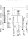
ここで、端末装置2A、2B、および2Cの各処理を、図17のシーケンス図を参照しながらさらに詳細に説明する。   Here, each process of the terminal devices 2A, 2B, and 2C will be described in more detail with reference to the sequence diagram of FIG.

端末装置2Bは、端末装置2Cとのセッションに障害が発生したことを検知すると、端末装置2CへBYEメッセージを送信する(図17の#811)。端末装置2Cは、BYEメッセージを受信すると(#821)、OKメッセージを端末装置2Bへ返信する(#822)。そして、端末装置2BがOKメッセージを受信すると(#812)、端末装置2Bおよび2Cは、両者間のセッションを切断する。   When the terminal device 2B detects that a failure has occurred in the session with the terminal device 2C, the terminal device 2B transmits a BYE message to the terminal device 2C (# 811 in FIG. 17). Upon receiving the BYE message (# 821), the terminal device 2C returns an OK message to the terminal device 2B (# 822). When the terminal device 2B receives the OK message (# 812), the terminal devices 2B and 2C disconnect the session between them.

端末装置2Bは、セッションの切断の処理と前後してまたは並行して、転送の依頼先を決定する(#813)。   The terminal device 2B determines a transfer request destination before or after or in parallel with the session disconnection process (# 813).

端末装置2Bは、転送先つまり端末装置2Aへ、INVITEメッセージを送信する(#814)。ただし、このINVITEメッセージは、転送用のセッションを確立するためのものである。つまり、前に図15で説明した転送依頼メッセージ7RQである。   The terminal device 2B transmits an INVITE message to the transfer destination, that is, the terminal device 2A (# 814). However, this INVITE message is for establishing a transfer session. That is, the transfer request message 7RQ described above with reference to FIG.

端末装置2Aは、転送依頼メッセージ7RQ(INVITEメッセージ)を受信すると(#801)、端末装置2Bとのセッションの確立および端末装置2Cとのセッションの確立の処理を次のように実行する。   When the terminal apparatus 2A receives the transfer request message 7RQ (INVITE message) (# 801), the terminal apparatus 2A executes the process of establishing a session with the terminal apparatus 2B and establishing a session with the terminal apparatus 2C as follows.

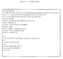
端末装置2Aは、INVITEメッセージを端末装置2Cへ送信する(#802)。このINVITEメッセージには、図18のように、呼識別子情報7MGa、転送先アドレス情報7MGb、およびデータ取扱情報7MGcが含まれる。   The terminal device 2A transmits an INVITE message to the terminal device 2C (# 802). The INVITE message includes call identifier information 7MGa, transfer destination address information 7MGb, and data handling information 7MGc as shown in FIG.

呼識別子情報7MGa、転送先アドレス情報7MGb、およびデータ取扱情報7MGcの意味は、それぞれ、転送依頼メッセージ7RQの呼識別子情報7RQa、転送先アドレス情報7RQb、およびデータ取扱情報7RQcの意味と同じである。本例では、呼識別子情報7MGaには、端末装置2AのIPアドレスが示される。転送先アドレス情報7MGbには、端末装置2BのIPアドレスが示される。データ取扱情報7MGcには、「sendonly」が示される。   The meanings of the call identifier information 7MGa, the transfer destination address information 7MGb, and the data handling information 7MGc are the same as the meanings of the call identifier information 7RQa, the transfer destination address information 7RQb, and the data handling information 7RQc of the transfer request message 7RQ, respectively. In this example, the call identifier information 7MGa indicates the IP address of the terminal device 2A. The forwarding address information 7MGb indicates the IP address of the terminal device 2B. The data handling information 7MGc indicates “sendonly”.

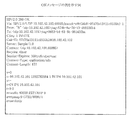
図17に戻って、端末装置2CがINVITEメッセージを受信すると、端末装置2Aおよび2Cは、図19に示すようなOKメッセージおよびACKメッセージをやり取りして、セッションを確立する(#826、#803、#804、#827)。   Returning to FIG. 17, when the terminal device 2C receives the INVITE message, the terminal devices 2A and 2C exchange an OK message and an ACK message as shown in FIG. 19 to establish a session (# 826, # 803, # 804, # 827).

ただし、端末装置2B、2C間のセッションの障害の原因が通信の不能または品質の著しい低下である場合は、端末装置2Cは、ステップ#821において端末装置2BからのBYEメッセージを受信できないことがある。そこで、もしも、端末装置2Cが端末装置2Bとのセッションの切断の処理を実行していない場合は、端末装置2AからINVITEメッセージを受信したタイミングで、端末装置2Bとのセッションの切断の処理を図る(#824、#825)。   However, when the cause of the failure of the session between the terminal devices 2B and 2C is an inability to communicate or a significant deterioration in quality, the terminal device 2C may not be able to receive the BYE message from the terminal device 2B in step # 821. . Therefore, if the terminal device 2C is not executing the process of disconnecting the session with the terminal device 2B, the process of disconnecting the session with the terminal device 2B is attempted at the timing when the INVITE message is received from the terminal device 2A. (# 824, # 825).

端末装置2Aおよび2Bは、端末装置2A、2C間のセッションの確立の処理と前後してまたは並行して、図20に示すようなOKメッセージおよびACKメッセージをやり取りし、両者間のセッションの確立の処理を実行する(#805、#817、#806、#818)。   The terminal devices 2A and 2B exchange an OK message and an ACK message as shown in FIG. 20 before or after or in parallel with the process of establishing a session between the terminal devices 2A and 2C. The process is executed (# 805, # 817, # 806, # 818).

その後、端末装置2Aは、図16において太線で示すように、新たに確立したセッションを用いて、端末装置2Cから送られてくるユーザUCの動画像および音声のデータを端末装置2Bへ転送し、端末装置2Bから送られてくるユーザUBの動画像および音声のデータを端末装置2Cへ転送する。   Thereafter, as shown by a thick line in FIG. 16, the terminal device 2A uses the newly established session to transfer the moving image and audio data of the user UC sent from the terminal device 2C to the terminal device 2B. The moving image and audio data of the user UB sent from the terminal device 2B are transferred to the terminal device 2C.

(II) 端末装置2Bおよび2Cがほぼ同時にセッションの障害を検知した場合
図21はセッションの変更の処理の流れの第二の例を示すシーケンス図である。
(II) When Terminal Devices 2B and 2C Detect Session Failures Almost Simultaneously FIG. 21 is a sequence diagram showing a second example of a session change processing flow.

端末装置2Bと端末装置2Cとが極短い所定の時間差で(つまり、同時にまたはほぼ同時に)両者間のセッションの障害を検知することがあり得る。その場合は、両者ともに、それぞれが有する接続順管理テーブル523(図5参照)に基づいて、図14で説明した手順で転送の依頼先を決定する。   It is possible that the terminal device 2B and the terminal device 2C detect a failure in a session between them with a very short predetermined time difference (that is, simultaneously or almost simultaneously). In that case, the transfer request destination is determined by the procedure described with reference to FIG. 14 on the basis of the connection order management table 523 (see FIG. 5) of both.

図6、図7、図8、および図9で説明した方法によると、端末装置2Bの接続順管理テーブル523および端末装置2Cの接続順管理テーブル523には、同一のレコードが同一の順位で格納される。さらに、図14で説明した方法によると、端末装置2Bの転送依頼先決定部551および端末装置2Cの転送依頼先決定部551は、ともに、同一の端末装置2を転送先として決定する。   According to the method described in FIG. 6, FIG. 7, FIG. 8, and FIG. 9, the same order is stored in the same order in the connection order management table 523 of the terminal device 2B and the connection order management table 523 of the terminal device 2C. Is done. Furthermore, according to the method described with reference to FIG. 14, both the transfer request destination determination unit 551 of the terminal device 2B and the transfer request destination determination unit 551 of the terminal device 2C determine the same terminal device 2 as the transfer destination.

よって、接続順管理テーブル523の内容が図5に示す通りである場合は、端末装置2Bの転送依頼要求部552も、端末装置2Cの転送依頼要求部552も、転送依頼メッセージ7RQを端末装置2Aに対して送信する。端末装置2Aは、一方の転送依頼メッセージ7RQを受け付け、もう一方の転送依頼メッセージ7RQを拒否する。そして、端末装置2Aは、端末装置2Bとのセッションを確立するとともに、端末装置2Cとのセッションを確立する。   Therefore, when the contents of the connection order management table 523 are as shown in FIG. 5, both the transfer request request unit 552 of the terminal device 2B and the transfer request request unit 552 of the terminal device 2C send the transfer request message 7RQ to the terminal device 2A. Send to. The terminal device 2A accepts one transfer request message 7RQ and rejects the other transfer request message 7RQ. Then, the terminal device 2A establishes a session with the terminal device 2B and also establishes a session with the terminal device 2C.

ここで、端末装置2A、2B、および2Cの各処理を、図21のシーケンス図を参照しながらさらに詳細に説明する。   Here, each process of the terminal devices 2A, 2B, and 2C will be described in more detail with reference to the sequence diagram of FIG.

端末装置2Bおよび2Cは、両装置間のセッションに障害が発生したことを検知すると、端末装置2Bは端末装置2CへBYEメッセージを送信し(図21の#841)、端末装置2Cは端末装置2BへBYEメッセージを送信する(#842)。端末装置2Bおよび2Cは、可能であれば、受信したBYEメッセージに対するOKメッセージを相手方へ返信する(#843、#853、#854、#844)。そして、端末装置2Bおよび2Cは、両者間のセッションを切断する。   When the terminal devices 2B and 2C detect that a failure has occurred in the session between the two devices, the terminal device 2B transmits a BYE message to the terminal device 2C (# 841 in FIG. 21), and the terminal device 2C receives the terminal device 2B. A BYE message is transmitted to (# 842). If possible, the terminal devices 2B and 2C return an OK message for the received BYE message to the other party (# 843, # 853, # 854, # 844). Then, the terminal devices 2B and 2C disconnect the session between them.

端末装置2Bおよび2Cは、自らの接続順管理テーブル523に基づいて転送の依頼先を決定する(#845、#855)。そして、それぞれが決定した依頼先(本例では、端末装置2A)へ転送依頼メッセージ7RQ(INVITEメッセージ)を送信する(#846)。   The terminal devices 2B and 2C determine the transfer request destination based on their own connection order management table 523 (# 845, # 855). Then, the transfer request message 7RQ (INVITE message) is transmitted to the determined request destination (in this example, the terminal device 2A) (# 846).

端末装置2Aは、端末装置2Bからの転送依頼メッセージ7RQおよび端末装置2Cからの転送依頼メッセージ7RQをほぼ同時に受信する(#831、#832)。すると、端末装置2Aは、一方を受け付け、もう一方を拒否する。以下、端末装置2Bからの転送依頼メッセージ7RQを受け付けた場合を例に説明する。   The terminal device 2A receives the transfer request message 7RQ from the terminal device 2B and the transfer request message 7RQ from the terminal device 2C almost simultaneously (# 831, # 832). Then, the terminal device 2A accepts one and rejects the other. Hereinafter, a case where the transfer request message 7RQ from the terminal device 2B is received will be described as an example.

端末装置2Aは、端末装置2Bからの転送依頼メッセージ7RQを受け付けると、それに対応して、端末装置2Bのデータの転送を通知するINVITEメッセージを端末装置2Cへ送信する(#833)。さらに、端末装置2Cからの転送依頼メッセージ7RQを拒否することを通知するメッセージを端末装置2Cへ通知する(#834)。   When the terminal device 2A receives the transfer request message 7RQ from the terminal device 2B, the terminal device 2A correspondingly transmits an INVITE message notifying the data transfer of the terminal device 2B to the terminal device 2C (# 833). Further, a message notifying that the transfer request message 7RQ from the terminal device 2C is rejected is notified to the terminal device 2C (# 834).

端末装置2Cは、端末装置2Aからの各メッセージに対する応答のメッセージを端末装置2Aへ返信する(#859、#860)。すると、端末装置2Aがそれらのメッセージを受信すると(#836、#837)、端末装置2Aおよび2Cは、両者間のセッションを確立する。   The terminal device 2C returns a response message to each message from the terminal device 2A to the terminal device 2A (# 859, # 860). Then, when the terminal device 2A receives these messages (# 836, # 837), the terminal devices 2A and 2C establish a session between them.

端末装置2A、2C間のセッションの確立の処理と前後してまたは並行して、端末装置2Aは、ステップ#831で受信した転送依頼メッセージ7RQ(INVITEメッセージ)を受け入れる旨のメッセージを返信し、端末装置2Bは、それに応答する(#838、#847、#848、#839)。そして、端末装置2Aおよび2Bは、両者間のセッションを確立する。   Before or after or in parallel with the process of establishing the session between the terminal devices 2A and 2C, the terminal device 2A returns a message to accept the transfer request message 7RQ (INVITE message) received in step # 831, The device 2B responds to it (# 838, # 847, # 848, # 839). And terminal device 2A and 2B establish the session between both.

図22は端末装置2の全体的な処理の流れの例を説明するフローチャートである。次に、端末装置2Aを例に、ある会議に用いられる際の端末装置2の全体的な処理の流れを、図22のフローチャートを参照しながら説明する。   FIG. 22 is a flowchart illustrating an example of the overall processing flow of the terminal device 2. Next, taking the terminal device 2A as an example, the overall processing flow of the terminal device 2 when used in a certain conference will be described with reference to the flowchart of FIG.

端末装置2Aは、主催者であるユーザが当会議への出席を求める者(被招待者)を指定すると(#11でYes)、被招待者それぞれの端末装置2とのセッションを確立するための処理を行う(#12)。この処理の手順は、前に図6で説明した通りである。   When the user who is the organizer designates a person (invited person) who wants to attend the conference (Yes in # 11), the terminal apparatus 2A establishes a session with the terminal apparatus 2 of each invited person. Processing is performed (# 12). The procedure of this process is as described above with reference to FIG.

または、端末装置2Aが主催者以外のユーザ(つまり、被招待者)によって使用される場合は、主催者の端末装置2からの要求に基づいて、参加者それぞれの端末装置2とのセッションを確立するための処理を行う(#13)。この処理の手順は、前に図7で説明した通りである。   Alternatively, when the terminal device 2A is used by a user other than the organizer (that is, an invitee), a session with each participant's terminal device 2 is established based on a request from the organizer's terminal device 2 Is performed (# 13). The procedure of this process is as described above with reference to FIG.

端末装置2Aは、他の参加者すべての端末装置2とのセッションの確立が完了すると、会議が終了するまで随時、ビデオカメラ3Vおよびマイク3Mによって得られた、ユーザUAの動画像および音声を、他の参加者すべての端末装置2へ配信する(#15)。さらに、他のユーザの動画像および音声を当該他のユーザ端末装置2から受信し再生する(#16)。また、転送の依頼を受けて代替用のセッションを確立している場合は(#17でYes)、受信した動画像および音声を、決められた他の端末装置2へ転送する(#18)。   When the terminal device 2A completes the establishment of the session with the terminal devices 2 of all other participants, the video and audio of the user UA obtained by the video camera 3V and the microphone 3M as needed until the conference is ended, Distribution to all the terminal devices 2 of other participants (# 15). Furthermore, the moving image and sound of another user are received from the other user terminal device 2 and reproduced (# 16). If an alternative session has been established in response to a transfer request (Yes in # 17), the received moving image and sound are transferred to another determined terminal device 2 (# 18).

さらに、端末装置2Aは、会議が終了するまで適宜、自らと他の端末装置2とのセッションの状態を監視する(#19)。監視方法は前に図11および図12で説明した通りである。そして、端末装置2Aは、障害を検知した場合は(#20でYes)、障害のあるセッションを使用して通信を行う相手側の端末装置2のデータを、他の端末装置2のうちのいずれに転送してもらうのかを決定し(#21)、決定した他の端末装置2に対して転送の依頼を行う(#22)。そして、決定した他の端末装置2との代替用のセッションを新たに確立する(#23)。依頼先の決定方法は、前に図14で説明した通りである。   Furthermore, the terminal device 2A appropriately monitors the state of the session between itself and another terminal device 2 until the conference ends (# 19). The monitoring method is as described above with reference to FIGS. If the terminal device 2A detects a failure (Yes in # 20), the terminal device 2A transmits data of the partner terminal device 2 that performs communication using the failed session to any of the other terminal devices 2. (# 21), and requests transfer to the other terminal device 2 that has been determined (# 22). Then, a substitute session with another determined terminal device 2 is newly established (# 23). The method of determining the request destination is as described above with reference to FIG.

一方、他の2台の端末装置2同士のセッションに障害が発生し、当該他の2台の端末装置2のうちのいずれかから転送の依頼を受けた場合は(#24でYes)、当該他の2台の端末装置2それぞれとの間に代替用の新たなセッションを確立する(#25)。例えば、端末装置2Bと端末装置2Cとの間のセッションの障害が発生した場合は、端末装置2A、2B間に代替用のセッションを確立し、端末装置2A、2C間に代替用のセッションを確立する。そして、その後は、ステップ#18において、図16に示したように、代替用のセッションを介して、ユーザUBの動画像および音声を端末装置2Cへ転送し、ユーザUCの動画像および音声を端末装置2Bへ転送する。   On the other hand, when a failure occurs in the session between the other two terminal devices 2 and a transfer request is received from one of the other two terminal devices 2 (Yes in # 24), A new alternative session is established between each of the other two terminal devices 2 (# 25). For example, when a failure occurs in a session between the terminal device 2B and the terminal device 2C, a substitute session is established between the terminal devices 2A and 2B, and a substitute session is established between the terminal devices 2A and 2C. To do. Then, in step # 18, as shown in FIG. 16, the moving image and sound of the user UB are transferred to the terminal device 2C via the alternative session, and the moving image and sound of the user UC are transferred to the terminal. Transfer to device 2B.

なお、代替用のセッションの確立の処理の手順は、前に図17および図21で説明した通りである。   Note that the procedure for establishing a substitute session is as described above with reference to FIGS.

本実施形態によると、障害が発生した2者間の通信を、予備の回線を用意することなく継続することができる。   According to this embodiment, it is possible to continue communication between two persons having failed without preparing a backup line.

さらに、障害があったセッションのみを切断すればよいので、正常な他のセッションをそのまま維持することができ、音声および映像の品質の低下を回避することができる。   Furthermore, since it is sufficient to disconnect only the session having a failure, it is possible to maintain another normal session as it is, and to avoid deterioration in the quality of audio and video.

また、フルメッシュ型の接続形態を採用しているので、MCU(Multipoint Control Unit)がなくても電子会議システムを実現することができる。   In addition, since a full mesh connection form is employed, an electronic conference system can be realized without an MCU (Multipoint Control Unit).

図23はセッションの変更後の端末装置2同士の接続形態の例を示す図である。本実施形態では、1つのセッションに障害が発生した場合に代替用のセッションを確立しデータの転送を送信したが、さらに別のセッションに障害が発生した場合も、代替用のセッションを確立しデータの転送を送信することができる。例えば、端末装置2B、2C間のセッションに障害が発生し代替用のセッションを確立した後、端末装置2C、2D間のセッションに障害が発生した場合は、図23に示すように、さらに代替用のセッションを確立しデータを転送するようにしてもよい。   FIG. 23 is a diagram illustrating an example of a connection form between the terminal devices 2 after the session is changed. In this embodiment, when a failure occurs in one session, an alternative session is established and data transfer is transmitted. However, even when a failure occurs in another session, an alternative session is established and data is transferred. Can be transferred. For example, when a failure occurs in the session between the terminal devices 2B and 2C and a substitute session is established, and a failure occurs in the session between the terminal devices 2C and 2D, as shown in FIG. The session may be established and data may be transferred.

本実施形態では、パケットのロス率に基づいて障害の有無を判定したが、一定の時間以上データのやり取りが行われていないセッションを、障害のあるセッションであると判定してもよい。   In the present embodiment, the presence / absence of a failure is determined based on the packet loss rate. However, a session in which data is not exchanged for a certain time or more may be determined as a failed session.

本発明は、電子会議システム以外の通信システム、例えば、多人数が参加するオンラインのゲームのシステムなどにも、適用することができる。   The present invention can also be applied to a communication system other than the electronic conference system, for example, an online game system in which a large number of people participate.

その他、電子会議システム1、端末装置2の全体または各部の構成、処理内容、処理順序、テーブルの構成などは、本発明の趣旨に沿って適宜変更することができる。   In addition, the entire configuration of the electronic conference system 1 and the terminal device 2, the configuration of each unit, the processing content, the processing order, the configuration of the table, and the like can be appropriately changed in accordance with the spirit of the present invention.

1 電子会議システム(通信システム)
2 端末装置(通信装置)
511 呼制御部
552 転送依頼要求部
553 転送セッション確立制御部
554 転送処理部
6 RTPパケット
1 Electronic conference system (communication system)
2 Terminal device (communication device)
511 Call control unit 552 Transfer request request unit 553 Transfer session establishment control unit 554 Transfer processing unit 6 RTP packet

Claims (5)

第一の通信装置と第二の通信装置との間で通信を行う通信方法であって、
前記第一の通信装置と前記第二の通信装置との間の第一のセッションに障害が発生した場合に、
前記第二の通信装置と、前記第一の通信装置から第一のデータを受信することができる第三の通信装置との間に、第二のセッションを確立し、
前記第一の通信装置と、前記第二の通信装置から第二のデータを受信することができる第四の通信装置との間に、第三のセッションを確立し、
前記第一のデータを、前記第三の通信装置から前記第二の装置へ前記第二のセッションを介して送信し、
前記第二のデータを、前記第四の通信装置から前記第一の装置へ前記第三のセッションを介して送信する、
通信方法。
A communication method for performing communication between a first communication device and a second communication device,
When a failure occurs in the first session between the first communication device and the second communication device,
Establishing a second session between the second communication device and a third communication device capable of receiving first data from the first communication device;
Establishing a third session between the first communication device and a fourth communication device capable of receiving second data from the second communication device;
Transmitting the first data from the third communication device to the second device via the second session;
Transmitting the second data from the fourth communication device to the first device via the third session;
Communication method.
相互にデータをやり取りすることができる第一の通信装置、第二の通信装置、および第三の通信装置を有する通信システムであって、
前記第一の通信装置は、
当該第一の通信装置と前記第二の通信装置との間のセッションの障害を検知する障害検知手段と、
前記障害が検知された場合に、当該第一の通信装置と前記第三の通信装置との間に、前記セッションの代替用の第一の代替セッションを確立する、第一の代替セッション確立手段と、
を有し、
前記第二の通信装置は、
前記障害が検知された場合に、当該第二の通信装置と前記第三の通信装置との間に、前記セッションの代替用の第二の代替セッションを確立する、第二の代替セッション確立手段、
を有し、
前記第三の通信装置は、
前記障害が検知された後、前記第一の通信装置から受信した第一のデータを、前記セッションの代わりに前記第二の代替セッションを介して前記第二の装置へ転送し、前記第二の通信装置から受信した第二のデータを、前記セッションの代わりに前記第一の代替セッションを介して前記第一の装置へ転送する、データ転送手段、
を有する、
通信システム。
A communication system having a first communication device, a second communication device, and a third communication device that can exchange data with each other,
The first communication device is:
Failure detection means for detecting a failure of a session between the first communication device and the second communication device;
First alternative session establishment means for establishing a first alternative session for substituting the session between the first communication device and the third communication device when the failure is detected; ,
Have
The second communication device is
Second alternative session establishment means for establishing a second alternative session for substituting the session between the second communication device and the third communication device when the failure is detected;
Have
The third communication device is:
After the failure is detected, the first data received from the first communication device is transferred to the second device via the second alternative session instead of the session, and the second data is transferred to the second device. Data transfer means for transferring the second data received from the communication device to the first device via the first alternative session instead of the session;
Having
Communications system.
第一の相手側装置と第一のセッションを介して通信する機能および第二の相手側装置と第二のセッションを介して通信する機能を有する通信装置であって、
前記第一のセッションの障害を検知する障害検知手段と、
前記障害が検知された場合に、当該通信装置と前記第二の相手側装置との間に、前記第一のセッションを代替するための代替セッションを確立する、代替セッション確立手段と、
当該通信装置が前記第二のセッションを介して発信した発信データを前記第一の相手側装置へ転送するように要求する、転送要求手段と、
前記第一の相手側装置から発信された相手側データを、前記代替セッションを介して前記第二の相手側装置から受信する、相手側データ受信手段と、
を有する通信装置。
A communication device having a function of communicating with a first counterpart device via a first session and a function of communicating with a second counterpart device via a second session,
A failure detection means for detecting a failure in the first session;
An alternative session establishing means for establishing an alternative session for substituting the first session between the communication device and the second counterpart device when the failure is detected;
Transfer request means for requesting that the communication device transmit outgoing data transmitted through the second session to the first counterpart device;
A counterparty data receiving means for receiving counterparty data transmitted from the first counterpart device from the second counterpart device via the alternative session;
A communication device.
第一の相手側装置と第一のセッションを介して通信する機能および第二の相手側装置と第二のセッションを介して通信する機能を有する通信装置であって、
前記第一の相手側装置から要求があった場合に、当該通信装置と前記第一の相手側装置との間に前記第一の相手側装置と前記第二の相手側装置との間のセッションの代替用のセッションである第一の代替セッションを確立し、当該通信装置と前記第二の相手側装置との間に前記第一の相手側装置と前記第二の相手側装置との間のセッションの代替用のセッションである第二の代替セッションを確立する、代替セッション確立手段と、
前記第一の相手側装置から前記第一のセッションを介して受信した第一のデータを、前記第二の代替セッションを介して前記第二の相手側装置へ転送し、前記第二の相手側装置から前記第二のセッションを介して受信した第二のデータを、前記第一の代替セッションを介して前記第一の相手側装置へ転送する、データ転送手段と、
を有する通信装置。
A communication device having a function of communicating with a first counterpart device via a first session and a function of communicating with a second counterpart device via a second session,
When there is a request from the first counterpart device, a session between the first counterpart device and the second counterpart device between the communication device and the first counterpart device A first alternative session, which is an alternative session, between the first counterpart device and the second counterpart device between the communication device and the second counterpart device An alternative session establishment means for establishing a second alternative session, which is a session substitute for the session;
Transferring the first data received from the first counterpart device via the first session to the second counterpart device via the second alternative session; and Data transfer means for transferring second data received from the device via the second session to the first counterpart device via the first alternative session;
A communication device.
第一の相手側装置と第一のセッションを介して通信する機能および第二の相手側装置と第二のセッションを介して通信する機能を有するコンピュータに用いられるコンピュータプログラムであって、
当該コンピュータに、
前記第一のセッションの障害を検知する処理を実行させ、
前記障害が検知された場合に当該通信装置と前記第二の相手側装置との間に前記第一のセッションを代替するための代替セッションを確立する処理を実行させ、
当該通信装置が前記第二のセッションを介して発信した発信データを前記第一の相手側装置へ転送するように要求する処理を実行させ、
前記第一の相手側装置から発信された相手側データを、前記代替セッションを介して前記第二の相手側装置から受信する処理を実行させる、
コンピュータプログラム。
A computer program used for a computer having a function of communicating with a first counterpart device via a first session and a function of communicating with a second counterpart device via a second session,
On that computer,
Causing the first session to detect a failure,
When the failure is detected, execute a process of establishing an alternative session for substituting the first session between the communication device and the second counterpart device,
Causing the communication device to execute a process of requesting to transfer the outgoing data transmitted through the second session to the first counterpart device,
Causing the other party data transmitted from the first other party apparatus to receive from the second other party apparatus via the alternative session;
Computer program.
JP2009011411A 2009-01-21 2009-01-21 Communication method, communication system, communication device, and computer program Withdrawn JP2010171663A (en)

Priority Applications (1)

Application Number Priority Date Filing Date Title
JP2009011411A JP2010171663A (en) 2009-01-21 2009-01-21 Communication method, communication system, communication device, and computer program

Applications Claiming Priority (1)

Application Number Priority Date Filing Date Title
JP2009011411A JP2010171663A (en) 2009-01-21 2009-01-21 Communication method, communication system, communication device, and computer program

Publications (1)

Publication Number Publication Date
JP2010171663A true JP2010171663A (en) 2010-08-05

Family

ID=42703363

Family Applications (1)

Application Number Title Priority Date Filing Date
JP2009011411A Withdrawn JP2010171663A (en) 2009-01-21 2009-01-21 Communication method, communication system, communication device, and computer program

Country Status (1)

Country Link
JP (1) JP2010171663A (en)

Cited By (2)

* Cited by examiner, † Cited by third party
Publication number Priority date Publication date Assignee Title
JP2016009875A (en) * 2014-06-20 2016-01-18 沖電気工業株式会社 Terminal device, communication control device, information processing method, and program
CN111567132A (en) * 2017-12-22 2020-08-21 三星电子株式会社 Electronic device and control method thereof

Cited By (3)

* Cited by examiner, † Cited by third party
Publication number Priority date Publication date Assignee Title
JP2016009875A (en) * 2014-06-20 2016-01-18 沖電気工業株式会社 Terminal device, communication control device, information processing method, and program
CN111567132A (en) * 2017-12-22 2020-08-21 三星电子株式会社 Electronic device and control method thereof
CN111567132B (en) * 2017-12-22 2023-12-12 三星电子株式会社 Electronic device and control method thereof

Similar Documents

Publication Publication Date Title
US9185051B2 (en) Supporting enhanced media communications using a packet-based communication link
EP3926917B1 (en) Data transmission method, device and computer storage medium
RU2483452C2 (en) Active speaker identification
CN107682657B (en) WebRTC-based multi-user voice video call method and system
EP2076998B1 (en) Method and apparatus for establishing multicast groups
US8149261B2 (en) Integration of audio conference bridge with video multipoint control unit
US9787844B2 (en) Conference bridge server
US8073956B2 (en) Multimedia communications using preferred devices
US8385234B2 (en) Media stream setup in a group communication system
WO2009129718A1 (en) A method, equipment and system for implementing file sharing in an audio/video conference
NO325064B1 (en) communications Client
CN101789956A (en) System and method for realizing digital family remote communication service
JP7463552B2 (en) SESSION CREATION METHOD, ELECTRONIC DEVICE, AND READABLE STORAGE MEDIUM
EP2822239B1 (en) Electronic conference system, bandwidth management method and storage medium in which bandwidth management program is stored
WO2020119229A1 (en) Electronic whiteboard control method, mobile terminal and electronic whiteboard system
JP2005311670A (en) Terminal, system and method for television conference, and program therefor
JP2010171663A (en) Communication method, communication system, communication device, and computer program
CN114338625B (en) Real-time communication method, device, equipment and storage medium
JP2005333446A (en) Teleconference system, teleconference method, and communication terminal
CA2484728C (en) Apparatus and method for distribution of streamed real-time information between clients
JP4917497B2 (en) Video distribution device, distribution video switching method, distribution video switching program, and distribution video switching program recording medium
JP2007324931A (en) Communication device, conference system, its control method and its program
CN113612734A (en) Cross-network remote court trial media stream transmission method and device
US9967345B2 (en) Split screen teleconferencing
CN110546947A (en) method for conducting an audio and/or video conference

Legal Events

Date Code Title Description
A300 Application deemed to be withdrawn because no request for examination was validly filed

Free format text: JAPANESE INTERMEDIATE CODE: A300

Effective date: 20120403