JP2010141910A - Receiving device - Google Patents
Receiving device Download PDFInfo
- Publication number
- JP2010141910A JP2010141910A JP2010014916A JP2010014916A JP2010141910A JP 2010141910 A JP2010141910 A JP 2010141910A JP 2010014916 A JP2010014916 A JP 2010014916A JP 2010014916 A JP2010014916 A JP 2010014916A JP 2010141910 A JP2010141910 A JP 2010141910A
- Authority
- JP
- Japan
- Prior art keywords
- data
- class
- length
- unit
- processing
- Prior art date
- Legal status (The legal status is an assumption and is not a legal conclusion. Google has not performed a legal analysis and makes no representation as to the accuracy of the status listed.)
- Granted
Links
Images


Landscapes
- Detection And Prevention Of Errors In Transmission (AREA)
- Mobile Radio Communication Systems (AREA)
Abstract
Description
本発明は、受信装置に係わり、特に、AMR(Adaptive Multi−Rate;適応マルチレート)方式などの音声符号化方式で符号化された所定送信時間間隔の音声符号を複数のクラスに分けると共に各クラスの音声符号をそれぞれ所定ビットレートに応じたビット数で表現し、所定クラスの音声符号に一定長のチェックコードを付加し、かつ、各クラスの音声符号に誤り訂正符号化処理を施し、各クラスの誤り訂正符号化処理が施された音声符号を、前記チェックコード付加クラスを先頭にして多重して送信する通信システムにおける受信装置に関する。 The present invention relates to a receiving apparatus, and in particular, classifies voice codes of a predetermined transmission time interval encoded by a voice coding system such as an AMR (Adaptive Multi-Rate) system into a plurality of classes and each class. Are represented by the number of bits corresponding to a predetermined bit rate, a check code of a certain length is added to a predetermined class of audio codes, and error correction coding processing is applied to each class of audio codes. The present invention relates to a receiving apparatus in a communication system that multiplexes and transmits a voice code that has been subjected to the error correction encoding process with the check code addition class at the head.
3GPP規格に準ずるW−CDMAシステムにおいて、端末装置は基地局装置から複数のトランスポートチャネルTrCHの多重データを受信する際、10msのフレーム毎に各フレームにマッピングされているTFCIビット(Transport Format Combination Indicator)を復号する。そして、このTFCIビットに基いて、各トランスポートチャネルTrCHのビットレート、すなわち単位時間あたりの情報ビット長(トランスポートフォーマット)を識別する。しかる後、端末装置は、識別したトランスポートフォーマットに基いて受信した多重データより各トランスポートチャネルの送信データを分離する。
ところで、低ユーザレートのチャネルに関しては、このTFCIビットが存在しない場合がある。その際、CRCチェックを利用したBTFD(Blind Transport Format Detection)処理により各トランスポートチャネルTrCHにおけるトランスポートフォーマットを判別して受信多重データより各トランスポートチャネルの送信データを再生する。
3GPP規格によれば、BTFD処理は音声符号の受信に際して適用される。すなわち、送信側の音声コーデック部は音声信号を例えばAMR方式により、(1)人間の声道を表現するLSPパラメータ、(2)音声の周期性を表現するピッチ周期成分、(3)音声に含まれる雑音成分、(4)ピッチ周期成分のゲイン、(5)雑音成分のゲインで表現し、入力音声よりこれら各要素を抽出して量子化し、量子化データを音声符号として出力する。LSPパラメータ、ピッチ周期成分、ピッチゲインは重要であり、第1のトランスポートチャネル(クラスAのTrCH)に分配し、雑音成分や雑音ゲインは少しぐらいエラーが乗っても致命的でないため、第2、第3のトランスポートチャネル(クラスB,CのTrCH)に分配する。
送信装置は、音声コーデック部より得られた各クラスの音声符号をそれぞれ所定ビットレートに応じたビット数で表現し、クラスAの音声符号に一定長のチェックコードを付加し、かつ、各クラスの音声符号に誤り訂正符号化処理を施し、各クラスの誤り訂正符号化処理が施された音声符号を、前記チェックコード付加クラスAを先頭にして多重して送信する。
受信装置は、CRCチェックを利用したBTFD処理により各クラスA〜CのトランスポートチャネルTrCHにおけるトランスポートフォーマット(ビット長)を判別し、該ビット長に基いて受信した各クラスの音声符号を抽出し、音声コーデックに入力し、音声コーデックは音声符号より音声信号を復元して出力する。なお、受信側において、受信物理チャネルは高位レイヤにてロジカルチャネルに遷移するが、物理チャネル〜ロジカルチャネルに遷移する間に、トランスポートチャネル(TrCH)という状態に遷移する。音声はTrCHが3チャネルで1つのロジカルチャネルとなり、各TrCHがそれぞれ、Class A,Class B,Class Cのトランスポートチャネルとなる。
図9は従来の移動局の構成図である。送信に際して、音声コーデック部1はマイク2から入力する音声信号を送信時間間隔TTI=20ms毎にAMR符号化方式により音声符号に変換し、クラスA〜Cの音声符号としてデータ分配部4に入力する。データ分配部4は音声コーデックからの指示によりクラスA〜Cの音声符号を選択的に符号化時間長20msの送信バッファ部51〜53に入力する。
各送信バッファ部51〜53はクラスA〜Cの音声符号(送信データ)を20ms毎に図示しないバッファメモリに書き込むと共に、次段のエンコード処理部61〜63に入力する。
エンコード処理部61〜63はそれぞれ時間20msの送信データを畳み込み符号あるいはターボ符号に従って符号化し(クラスAについてはCRCチェックビット付加後)、フレーム単位(10ms単位)に分割して多重部7に入力する。多重部7は各エンコード処理部61〜63から入力する誤り訂正符号化データを10ms毎に多重して1フレーム分の多重データを作成し、多重された符号化データを同相成分(IN−Phase component)データとして送出する。
制御信号発生部8はパイロットPILOT、TFCI、TPCなどの制御データを直交成分(Quadrature component)データとして一定シンボル速度で出力する。QPSK拡散&変調器9のQPSK拡散器9aは入力される同相成分(Ich成分)、直交成分(Qch成分)に所定の拡散コードを用いて拡散変調を施し、DA変換してQPSK直交変調器9bに入力する。直交変調器9bはIch信号、Qch信号にQPSK直交変調を施し、無線送信部10は直交変調器から出力するベースバンド信号を高周波数に周波数変換(IF→RF)すると共に、高周波増幅等を行ってアンテナANTTより送信する。
受信に際して、無線受信部11はアンテナATNRにより受信した高周波信号をベースバンド信号に周波数変換(RF→IF変換)し、しかる後、ベースバンド信号を直交検波して同相成分(I成分)データと直交成分(Q成分)データを発生し、AD変換して逆拡散復調部12に入力する。逆拡散復調部12はI成分信号、Q成分信号に拡散符号と同じ符号を用いて逆拡散処理を施し、送信されてきた符号化データを復調(同期検波)し、分離部13に入力する。
分離部13は入力する多重データよりフレーム毎(10ms毎)にクラスA〜Cのデータを分離し、それぞれデコード処理部141〜143に入力する。各デコード処理部141〜143は10msのデータを2つ結合して送信時間間隔TTI=20msのデータにし、しかる後、クラスA〜Cのデータに誤り訂正復号処理を施して元のクラスA〜Cの音声符号データを復号し、受信バッファ部151〜153のバッファメモリに書き込む。受信バッファ部151〜153はバッファメモリから同期してクラスA〜Cの音声符号データを読み出してデータ分配部4に入力し、データ分配部4は各クラスの音声符号データを音声コーデック1に入力する。音声コーデック部1は音声符号より音声信号を復元してスピーカ3より出力する。
以上要約すれば、W−CDMAシステムにおける送信側チャネルコーデック部21は、上位レイヤよりクラスA〜Cの音声符号データを受け取り、クラスA〜Cのトランスポートチャネル(TrCH)毎に符号化処理を行ない、符号化したデータを多重して物理チャネルにマッピングして送信する。逆に、受信側チャネルコーデック部22は、物理チャネル上の多重データよりクラスA〜Cのトランスポートチャネル(TrCH)毎にデータを分離して復号処理を行ない、その結果(クラスA〜Cの音声符号)を上位レイヤに受け渡す。
送信側の音声コーデック部1は前述のようにマイク2から入力する音声信号を送信時間間隔TTI=20ms毎にAMR符号化方式により音声符号に変換し、クラスA〜Cの音声符号としてデータ分配部4に入力するが、各クラスの音声符号のビットレート(ビット長)は呼接続時に基地局から指示される。すなわち、基地局は呼接続時に各クラスA〜Cのビットレートの組み合わせ候補を複数、発信端末及び着信端末にそれぞれ通知すると共に、どの組み合わせのビットレートで音声符号を送信するか指示する。図10は3GPP規格における音声フォーマット(ビットレートの組み合わせ候補)の一例であり、TTI=20ms毎に符号化した各クラスA〜Cの音声符号を表現するためのビット長を示している。図10には10種類のビットレートの組み合わせが示され、それぞれを特定するためにフレームタイプ番号が付されている。ビットレートの組み合わせ候補は分類すると、(1)無音のビットレート組み合わせ(1111)、(2)背景雑音のビットレート組み合わせ(0001)、(3)有音のビットレート組み合わせ(0000〜1110)がある。有音の場合、どのビットレート組み合わせを使用するかは、呼接続時の通信トラフィックによって決定される。具体的には、トラフィックが空いているときは、高ビットレート12.2kbpsで高品質の音声データのやりとりを行うが、逆にトラフィックが混んでいるときは、混雑度に応じて低いレートに変えて送受信データのビット長を小さくする。なお、有音のビットレートの組み合わせは呼接続時に一度、決定されると終話時まで、そのビットレートは維持され、中間でビットレートの切り替えはしない。現状では、有音のビットレート組み合わせは12.2kbpsのフレームタイプ1110だけである。
背景雑音は聴感上の自然さを与えるために必要なものである。人間の会話には、音声のある区間(有音区間)と、話の区切りや相手の話を黙って聞いている音声の無い区間(無音区間)が存在する。また、一般には、音声にオフィス、自動車または街路などで生じる背景雑音が重畳される。従って、実際の音声通信では、音声に背景雑音が重畳されている区間(有音区間)と背景雑音のみの区間(無音区間)が存在することになる。そのため、無音区間を検出し、無音区間の情報伝送を停止することにより大幅な伝送量の削減が可能となる。しかし、無音区間で何もしないか、あるいは一定レベルの雑音を出力せざるを得ないため不自然で、聴取者に違和感が生じる。そこで、図11に示すように無音状態が継続し、7回無音フレームが連続したとき、背景雑音を生成するために必要な1つの背景雑音フレームを挿入し、これにより背景雑音の伝送量を少なくしつつ、受信側で自然な違和感の無い再生を可能にする。
基地局は呼接続時に図10に示す各クラスA〜Cのビットレートの組み合わせ候補を発信端末及び着信端末にそれぞれ通知すると共に、フレームタイプ番号でどの組み合わせのビットレートで音声符号を送信するかを指示する。発信端末の音声コーデック部1(図9)は、基地局より指示されたビット長で各クラスの音声符号を表現し、送信側チャネルコーデック部21はクラスAの音声符号に一定長のCRCチェックコードを付加し、各クラスの音声符号に誤り訂正符号化処理を施し、フレーム単位(10ms単位)に分割し、各クラスの誤り訂正符号化データを10ms毎に多重して1フレーム分の多重データを作成して送出する。着信端末の受信側チャネルコーデック部22は多重データより各クラスのデータを分離し、それぞれに復号処理を施す。
図12は分離された後のTTI=20msの各クラスのデータ構成であり、(A)はクラスAのデータ構成図、(B),(C)はクラスB,Cのデータ構成図である。クラスAのデータは、(1)基地局より指示されたフレームタイプに応じたビット長を有するクラスAの音声符号部分A1、(2)一定長のCRCチェック符号部分A2、(3)エンプティ部分A3で構成されている。クラスB,Cのデータは、(1)基地局より指示されたフレームタイプに応じたビット長の音声符号部分B1,C1、(2)エンプティ部分B2,C2で構成されている。尚、エンプティ部分には信号の送信がされていないが、雑音による信号が送信されている。
受信側チャネルコーデック22は図12に示す構成のデータより音声符号部分A1,B1,C1(雑音による信号を除去して)のみを正確に切り取って音声コーデック部に入力しなければならない。そこで、従来はCRCチェックを利用したBTFD(Blind Transport Format Detection)処理により各クラスの音声符号のビット長を判別して分離する。すなわち、受信側チャネルコーデック部22は、クラスAの音声符号が、図10に示す各フレームタイプにおけるクラスAの単位時間当たりのビット数(0,39,42,49,..81)で表現されているものと仮定して受信データに誤り訂正復号処理を施す。尚、ビット数の小さい順に番号nend=1,2,..が付される。
しかる後、復号データに対してCRCチェックにより全てのパターンについて一通り復号結果が正しいかの検査を行ってから、該検査により復号結果が正しいと判定したものを検索し、図10を参照してその時のビットレートの組み合わせにおける各クラスの単位時間当たりのビット数(ビットレート)を求め、該ビット数を各クラスの音声符号を表現するビット数であると判別する。各クラスのビット長が判別すれば、受信側チャネルコーデック22は図12(A)〜(C)に示す構成のデータより音声符号部分のみを正確に切り取って音声コーデック部に入力する。
以下ではBTFD処理について説明するが、その前にBTFD処理を理解する上で必要な畳み込み符号及びビタビ復号を説明する。
図13は畳み込み符号器の例であり、2ビットのシフトレジスタSFRと2つの排他的論理和回路EXOR1,EXOR2を備え、EXOR1は入力とR1の排他的論理和g0を出力し、EXOR2は入力とR0とR1の排他的論理和g1(”1”が奇数のとき出力は”1”、それ以外は”0”)を出力する。したがって、入力データが01101の場合における畳み込み符号器の入出力関係及びシフトレジスタSFRの状態は図14に示すようになる。
畳み込み符号器のシフトレジスタSFRの内容はstate(状態)と定義され、図15に示すように00,01,10,11の4つの状態があり、それぞれを状態a,状態b,状態c,状態dと表現する。図13の畳込み符号器ではシフトレジスタSFRの状態がa〜dのいずれの状態であるか、及び、次に入力するデータが”0”であるか”1”であるかにより、出力(g0,g1)及び次の状態が一意に決まる。図16はかかる畳込み符号器の状態と入出力の関係図であり、点線は”0”入力、実線は”1”入力を示している。例えば、
(1)状態aにおいて、”0”が入力すると出力は00で状態はaになり、”1”が入力すると出力は11で状態はcになる。
(2)状態bにおいて、”0”が入力すると出力は11で状態はaになり、”1”が入力すると出力は00で状態はcになる。
(3)状態cにおいて、”0”が入力すると出力は01で状態はbになり、”1”が入力すると出力は10で状態はdになる。
(2)状態dにおいて、”0”が入力すると出力は10で状態はbになり、”1”が入力すると出力は01で状態はdになる。
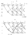
この入出力関係を用いて図13の畳み込み符号器の畳み込み符号を格子状表現すると図17(a)に示すようになる。ただし、kは第kビット入力時点を意味し、符号器における初期(k=0)の状態はa(00)である。又、点線”0”入力、実線は”1”入力を示し、線上の2つの数値は出力(g0,g1)を示している。したがって、初期状態a(00)において、”0”が入力すると出力は00で状態はaになり、”1”が入力すると出力は11で状態はcになることがわかる。
この格子状表現図を参照すると、原データが11001であれば、図17(b)の2点鎖線で示すパスを介して状態cに至り、符号器出力は
11→10→10→11→11
となることがわかる。
復号器の受信データ(g0,g1)が11→10→10→11→11で誤りのない理想状態を想定すると、図18(a)の2点鎖線で示すパスが得られ、点線を”0”、実線を”1”とすることにより、図18(b)に示すように11001の復号結果を得ることができる。しかし、実際には、受信データに誤りが含まれる場合が多い。図18(c)に示すように、第5ビット目に誤りが発生し、硬判定受信データ(g0,g1)が11→10→00→11→11であるとすると、k=2のデータ入力時点で10,01のどちらへ分岐すべきか迷う(エラー回数ERR=1)。10とみなして上側のパスを選択すると、k=3,k=4で迷うこと無く状態cに至る。したがって、2点鎖線パスでのエラー回数ERR=1となり、その時の復号結果は11001となる。一方、k=2のデータ入力時点で01とみなして下側のパスを選択すると、k=3の時点でも、どちらへ分岐すべきか迷い、総エラー回数ERR=2となる。以後、同様にパスを選択し、分岐に迷った時にERRをカウントアップすると、最終的に以下の結果が得られる。すなわち、
復号結果を11001とした時の総エラー回数ERR:1
復号結果を11100とした時の総エラー回数ERR:2
復号結果を11101とした時の総エラー回数ERR:4
復号結果を11110とした時の総エラー回数ERR:3
復号結果を11111とした時の総エラー回数ERR:3
となる。そこで、エラー回数ERRが最小の復号結果11001を選択して出力する。このようにすれば、受信データに誤りがあっても原データ11001を正しく復元できる。
ところで、以上のように受信データに基づいて可能な全パスのエラー回数ERRを求め、そのうち最小のパスより原データを復号する処理は煩雑である。そこで、ビタビ復号は以下のように行う。尚、受信データは硬判定の結果111000であったとする。図18のk=3の状態aでは、2つの入力パスがある。その該当するパスのみを取り出して記述したものを図19(a)に示す。2つのパスとは図中に示したパス(1)とパス(2)である。受信データと各パスで得られる復号データとの間のハミング距離(以後、パスメトリック値という)を計算すると図19(b)、(c)に示すように、それぞれ3、4となる。
この計算結果から、「パス(1)をたどって状態aに到達した」と仮定する方のパスメトリック値が、「パス(2)をたどって状態aに到達した」と仮定するより小さい。そのため、パス(1)の方が送信されたデータに応じたパスであるという信頼性が高いため生き残りとして残し、他のパスを捨てる。このパスの取捨選択処理を各状態a〜dについて、時間k=1から連続して実行すると任意の時間kにおける各状態a,b,c,dにそれぞれ至るパスメトリック値が最小のパス(エラー最小のパス)を求めることができ、以後、同様の取捨選択処理を継続することができる。
以上より、N個の受信データが入力したとき、k=Nにおける各状態a,b,c,dにそれぞれ至るパスメトリック値最小(エラー最小)の4本のパスのうち、パスメトリック値が最小のパスを決定し、該パスに基づいて復号データを出力する。図20は受信データ1110 00 11 11であるときの各時間k(=1〜5)の各状態a〜dに至る最短パスを示しており、線上の数値はパスメトリック値である。k=5のデータ入力時点では、状態cに至るパスのパスメトリック値が最小となる。従って、k=5の時点の状態cから該パスに沿ってトレースバック処理を行うとデータ11001が得られ、これが復号データとなる。以上の復号アルゴリズムがViterbiアルゴリズムである。
なお、k=nendのデータ入力時点における状態a(=状態0)のパスメトリック値をa0(nend)、各状態a〜dのうち最大のパスメトリック値をamax(nend)、各状態のうち最少のパスメトリック値をamin(nend)とおくと、符号化データに対して誤りが少ないほどa0(nend)>amin(nend)の関係が顕著になる特性がある。すなわち、符号化データに対して誤りが少ないほどa0(nend)はより大きくなり、amin(nend)はより小さくなる特性がある。このため、[amax(nend)−amin(nend)]に対する[a0(nend)−amin(nend)]の割合は大きくなる。この特性より、次式
S(nend)=−10 log[{a0(nend)−amin(nend)}/{amax(nend)−amin(nend)}][dB] (1)
で与えられるS(nend)値は、誤りが少ないほど小さくなる。BTFD処理においてはこのS(nend)値が用いられる。BTFD処理は図21にしたがって詳細に説明するが、概略、以下の処理を段階的に行う。すなわち、
(a)ビットレートの候補が複数指定される。
(b)各ビットレート候補におけるクラスAのビットレートに対して、ビットレートの小さい順(nendの小さな順)にビタビ復号を行い、Add−Compare−Select(以後、ACS)処理を行いパスメトリック値を求め、そのパスメトリック値を用いて(1)式によりS(nend)を計算する。
(c)S(nend)と閾値Dとの大小判断を行う。
(d)S(nend)が閾値Dより小さければ、最終ビット位置においてパスメトリック値が最小の状態から、トレースバック処理を行う。
(e)トレースバック処理によりえられた復号データに対してCRCチェックを行う。
(f)CRCチェックがOKであれば、今回のS(nend)とそれまでの最小値であるSminとの比較をおこなう。
(b)〜(f)をビットレートの候補数分行い、CRCチェック結果がOKで、かつ、最終的に最も確からしいもの、すなわち、S(nend)が最小のビットレート候補を選択する。このビットレート候補における各クラスのビット数が各クラスの音声符号を表現するビット数であると決定する。ただし、(c)の結果、S(nend)が閾値Dより大きい場合、つまり、確からしさが低い場合は(d),(e),(f)の処理は行わない。
図21はBTFD処理フローである。
上位アプリケーションよりビットレートの候補(図10)が指定されるから、クラスAのビットレート(単位時間当たりのビット数)の小さい順に番号付けし、nend=1,2,3,...とする(ステップ101)。ついで、nend=1、Smin=D、nend′=0と初期化する(ステップ102)。
しかる後、nend位置までACS処理を行い(ステップ103)、(1)式によりS(nend)を計算する(ステップ104)。S(nend)が求まれば、このS(nend)と閾値Dとの大小判断を行う(ステップ105)。
S(nend)≦Dであれば、nend位置のパスメトリック値が最小の状態から、トレースバック処理を行う(ステップ106)。ついで、トレースバック処理により得られた復号データに対してCRCチェックを行う(ステップ107)。CRCチェックがOKであれば、今回のS(nend)とそれまでの最小値であるSminとの比較を行う(ステップ109)。
Smin>S(nend)であればSmin=S(nend)として最小値を更新すると共に、nend′=nendとしてその時のnend、すなわち、クラスAにおける音声符号のビット数を保存する(ステップ110)。しかる後、nendが最後の候補であるかチェックし(ステップ111)、最後でなければnend=nend+1によりnendを歩進し(ステップ112)、ステップ103以降の処理を繰り返す。
一方、ステップ105において、S(nend)>Dであれば、あるいは、ステップ108において、CRCチェックがNOであれば、あるいは、ステップ109において、Smin≦S(nend)であれば、ステップ111の処理を行う。
全候補のnendについて上記処理を繰り返せば、ステップ111において「YES」となるから、nend′=0であるかチェックし(ステップ113)、「YES」であればエラー出力する(ステップ114)。しかし、nend′=0でなければ、該nend′が最も確からしいビットレートの組み合わせにおけるクラスAのビットレート(ビット数)と判定し、出力する(ステップ115)。以後、図10のビットレートの組み合わせ候補を参照して他のクラスのビットレート(ビット数)を求める。
図22はBTFD処理を実行する受信側チャネルコーデック部の構成図である。図示しない分離・結合部は多重データよりクラス毎に分離したデータをクラス毎に結合してTTI=20msの各クラスのデータを作成する。受信データメモリ部22aは、このTTI=20msの各クラスのデータを受信して保持する。ビタビ復号部22bはACS演算/パスメトリックメモリ/パスメモリ部31、トレースバック部32、トレースバック後メモリ33を備えている。パスメモリは各時点kにおいて、状態a,b,c,dにそれぞれ至るパスメトリック値が最小の4本のパスをそれぞれ記憶するもの、パスメトリックメモリは各パスのパスメトリック値を記憶するものである。図20のk=5の例では、
状態aに到るパスは11100でパスメトリック値は2、
状態bに到るパスは11110でパスメトリック値は3、
状態cに到るパスは11001でパスメトリック値は1、
状態dに到るパスは11111でパスメトリック値は3、
である。トレースバック部32は状態a,b,c,dに到る4本のパスのうちパスメトリック値が最小となるパスを決定し、該パスに沿ってトレースバック処理を行って復号データを求めてトレースバック後メモリ33に保存する。
ビタビ復号部は、Aクラスについてはnend位置までのデータに対してビタビ復号処理を施す。又、B,Cクラスについてはデータ長が判らないため末尾位置までのビタビ復号処理を行い、各データ長候補に対応する時点kにおいて、状態a,b,c,dにそれぞれ至るパスメトリック値が最小の4本のパスをパスメモリに記憶し、それぞれのパスメトリック値をパスメトリックメモリに記憶する。
CRC演算部22cはクラスAの復号結果に基づいてCRCチェック演算を行う。CRCチェック演算後メモリ22dは、図9における受信バッファ15に相当するもので、CRCチェックOKとなり、且つ、SminとなったときのクラスAの復号データ(音声符号)を記憶する。又、トレースバック部はBTFD処理により決定されたクラスB,Cのビット数に対応する時点kにおける4本のパスのうちパスメトリック値が最小のパスを求め、該パスに沿ってトレースバック処理を行って該クラスB,Cの音声符号を取得し、CRCチェック演算後メモリ22dに記憶する。
BTFD制御部は22eは、図21のフローにしたがってBTFD処理を行って各クラスの音声符号のビット数を決定するものであり、候補レート設定/保持部34は上位レイヤ(上位アプリケーション)41より通知される複数のビットレート候補を保持すると共に、受信データメモリ部22aに所定のビットレートを設定する。
上位レイヤ(上位アプリケーション)41から、あらかじめ、音声の候補レート情報(図10に示すクラスA,B,Cのbit長)がBTFD制御部22eに通知され、候補レート設定/保持部34は通知された候補レート情報(ビットレート組み合わせ情報)を保持する。
一方、図示しない分離部で分離された各クラスの受信データは受信データメモリ部22aに保持され、BTFD制御部22eの候補レート設定/保持部34は複数のビットレート組み合わせ候補におけるクラスAのビットレートを小さい順に受信データメモリ部22aに設定する。
ビットレートを受け取った受信データメモリ部22aは、該ビットレートに応じたビット数のクラスAの受信データをビタビ復号部のACS演算/パスメトリックメモリ/パスメモリ部31に入力する。ACS演算/パスメトリックメモリ/パスメモリ部31はACS演算を行い、その演算結果であるパスメトリック値を内蔵のパスメトリックメモリに保持するとともに、最大パスメトリック値amax(nend)、最少パスメトリック値amin(nend)、状態a(状態0)のパスメトリック値a0(nend)をそれぞれBTFD制御部22eに通知する。
BTFD制御部22eは、S(nend)の計算を行い、さらに、S(nend)と閾値Dとの比較を行う。その結果、トレースバックを行うと判断すれば、トレースバック部32に対して、トレースバック起動情報を入力する。これによりトレースバック部32はトレースバックを行い、nend位置までの復号結果をトレースバック後メモリ部33に保存する。
しかる後、受信データメモリ部22aは、最大レートの組み合わせ(図10の例ではフレームタイプ1110)におけるクラスB,Cのビットレートに応じたビット数のクラスB、クラスC受信データをビタビ復号部22bに入力し、ビタビ復号部22bはビタビ復号処理を行い、得られたパスをパスメモリ部に保存する。すなわち、前述のように、各データ長候補に対応する時点kにおいて、状態a,b,c,dにそれぞれ至るパスメトリック値が最小の4本のパスをパスメモリに記憶し、それぞれのパスメトリック値をパスメトリックメモリに記憶する。
クラスAの復号が終了すれば、トレースバック後メモリ部33はCRC演算部22cにBTFD制御部22eから通知されたビットレート組み合わせ情報が指示するクラスAのビット数+CRCチェック符号数分の復号結果を入力する。CRC演算部22cはCRCチェック演算を行い、そのCRCチェック結果をBTFD制御部22eに通知する。BTFD制御部22eは、そのCRCチェック結果をもとに、図21の処理フローにしたがってSminとS(nend)の大小を比較し、Smin>S(nend)であれば、Smin、nend′値の更新を行う。又、CRCチェックがOKで、かつ、Smin>S(nend)の条件が成立すればCRCチェック符号を削除した復号結果をそれまでの復号結果に替えてCRC演算後メモリ22dに保存する。以後、BTFD制御部22eは、クラスAについて上記処理をビットレート組み合わせ候補分行えば、その時のnend′値に応じたビット数をクラスAの音声符号のビット数であると認識する。なお、nend′値に応じたビット数のクラスAの音声符号データは既にCRC演算後メモリ22dに格納されている。
ついで、BTFD制御部22eは、ビットレート組み合わせ候補テーブル(図10)とクラスAのビット数とからクラスB,Cの音声符号のビット数を識別する。以後、BTFD制御部22eは、トレースバック部32を起動し、該トレースバック部はパスメモリ部から、クラスB,Cのビット長に相当する時点kにおける4本のパスのうちパスメトリック値が最小のパスを求め、該パスに沿ってトレースバック処理を行って該クラスB,Cの音声符号を取得しCRC演算部22c経由でCRC演算後メモリ22dに格納する。CRC演算後メモリ22dはクラスA,B,Cの音声符号がそろったところで、これら音声符号を音声コーデック部1に1論理チャネルとして送り、音声コーデック部1は受信した音声符号より音声信号を復元する。
3GPP規格にのっとった従来のBTFD処理では、図21の処理フローより明らかなように、ビットレートすなわちデータ長の短い順にビタビ復号処理、CRCチェック演算を行い、最終的に全てのビットレート組み合わせ候補について処理した後に、最も確からしい各クラスの音声符号のデータ長を決定し、受信データより各クラスの音声符号データを切り取って音声コーデック部に入力する。しかし、かかる従来方法では、毎回全てのレート候補について演算するので、処理量が非常に多くなり、消費電流も増加する問題がある。
従来のBTFD処理シーケンスでは、真の音声符号と異なるデータ長においてもCRCチェックOKが生じることを想定しているため、全ての候補について検出処理を行って特性上良い方に基いて各クラスの音声符号のビット長を決定している。しかし、本来送信している真のデータ長以外で、CRCチェックOKが生じる確率は、CRC−SIZE=12bitとして、2−12であり、この処理による特性の改善は、微小であると考えざるを得ない。
また、ビットレート組み合わせ候補が無音用、背景雑音用、12.2k音声データ用の3つの場合を考えると、通話中は12.2k音声データがある程度続く。それにも拘わらず、従来のシーケンスでは、毎回、無音、背景雑音、12.2k音声データの順(レートが小さい順)にビタビ復号処理、CRCチェック演算を行い、結局12.2k音声データが正しいことを検出して受信するため、処理量が多く消費電流も増加する問題がある。
また、従来のBTFD処理シーケンスでは、ビタビ復号、トレースバック処理、CRC演算を終えた各クラスの復号結果を一旦CRC演算後メモリ22dに格納する。このように従来のBTFD処理シーケンスでは、トレースバック後メモリ部とCRC演算後メモリの両方が必要になるため使用するメモリ数が非常に多くなる問題がある。
In a W-CDMA system conforming to the 3GPP standard, when a terminal apparatus receives multiplexed data of a plurality of transport channels TrCH from a base station apparatus, a TFCI bit (Transport Format Combination Indicator) mapped to each frame every 10 ms frame ). Based on this TFCI bit, the bit rate of each transport channel TrCH, that is, the information bit length (transport format) per unit time is identified. Thereafter, the terminal device separates the transmission data of each transport channel from the multiplexed data received based on the identified transport format.
By the way, this TFCI bit may not exist for a low user rate channel. At this time, the transport format in each transport channel TrCH is determined by BTFD (Blind Transport Format Detection) processing using CRC check, and the transmission data of each transport channel is reproduced from the received multiplexed data.
According to the 3GPP standard, BTFD processing is applied when a voice code is received. That is, the audio codec section on the transmission side includes an audio signal in, for example, the AMR method, (1) an LSP parameter that represents the human vocal tract, (2) a pitch period component that represents the periodicity of the audio, and (3) an audio signal The noise component is expressed by (4) the gain of the pitch period component, and (5) the gain of the noise component. These elements are extracted from the input speech, quantized, and the quantized data is output as a speech code. The LSP parameter, pitch period component, and pitch gain are important and are distributed to the first transport channel (Class A TrCH), and the noise component and noise gain are not fatal even if there is a slight error. And distributed to the third transport channel (TrCH of class B and C).
The transmitting device expresses each class of speech code obtained from the speech codec unit by the number of bits corresponding to a predetermined bit rate, adds a check code of a certain length to the class A speech code, and The voice code is subjected to error correction coding processing, and the voice code subjected to the error correction coding processing of each class is multiplexed and transmitted with the check code addition class A at the head.
The receiving device discriminates the transport format (bit length) in the transport channel TrCH of each class A to C by BTFD processing using CRC check, and extracts the received speech code of each class based on the bit length. The audio codec restores the audio signal from the audio code and outputs it. On the receiving side, the reception physical channel transits to a logical channel in a higher layer, but transits to a state called a transport channel (TrCH) while transiting from a physical channel to a logical channel. As for voice, three channels of TrCH become one logical channel, and each TrCH becomes a transport channel of Class A, Class B, and Class C, respectively.
FIG. 9 is a block diagram of a conventional mobile station. At the time of transmission, the
Each
Encoding processing unit 6 1 ~ 6 3 Respectively encodes the transmission data of 20 ms in time according to a convolutional code or a turbo code (after adding CRC check bit for class A), divides it into frame units (10 ms units), and inputs them to the
The
At the time of reception, the
The
In summary, the transmission-side
As described above, the
Background noise is necessary to give a natural sense of hearing. In a human conversation, there are a section with sound (sound section) and a section without speech (silent section) in which a voice is heard while silently listening to a story break or the other party's story. In general, background noise generated in an office, a car, a street, or the like is superimposed on the voice. Therefore, in actual voice communication, there are a section in which background noise is superimposed on speech (sounded section) and a section having only background noise (silent section). Therefore, it is possible to significantly reduce the transmission amount by detecting the silent section and stopping the information transmission in the silent section. However, nothing is done in the silent section, or a certain level of noise must be output, which is unnatural and causes the listener to feel uncomfortable. Therefore, as shown in FIG. 11, when the silent state continues and seven silent frames continue, one background noise frame necessary for generating the background noise is inserted, thereby reducing the transmission amount of the background noise. On the other hand, it is possible to perform playback without a natural discomfort on the receiving side.
At the time of call connection, the base station notifies each of the class A to C bit rate combination candidates shown in FIG. 10 to the transmitting terminal and the receiving terminal, and at what combination bit rate is transmitted by the frame type number. Instruct. The voice codec section 1 (FIG. 9) of the transmitting terminal expresses each class of voice code with the bit length specified by the base station, and the transmission side
FIG. 12 shows the data structure of each class of TTI = 20 ms after separation, (A) is a data structure diagram of class A, and (B) and (C) are data structure diagrams of classes B and C. Class A data includes (1) a class A speech code part A1 having a bit length corresponding to the frame type instructed by the base station, (2) a CRC check code part A2 having a fixed length, and (3) an empty part A3. It consists of Class B and C data is composed of (1) bit length speech code parts B1 and C1 corresponding to the frame type specified by the base station, and (2) empty parts B2 and C2. In addition, although a signal is not transmitted to the empty part, a signal due to noise is transmitted.
The receiving-
Thereafter, after checking whether the decoding result is correct for all patterns by CRC check on the decoded data, a search is made for a result that the decoding result is determined to be correct by referring to FIG. The number of bits per unit time (bit rate) in the combination of bit rates at that time is obtained, and the number of bits is determined to be the number of bits representing the speech code of each class. If the bit length of each class is determined, the receiving-
Hereinafter, BTFD processing will be described, but before that, convolutional codes and Viterbi decoding necessary for understanding BTFD processing will be described.
FIG. 13 shows an example of a convolutional encoder, which includes a 2-bit shift register SFR and two exclusive OR circuits EXOR1 and EXOR2, and EXOR1 has an input and R 1 Exclusive OR of 0 , EXOR2 is input and R 0 And R 1 Exclusive OR of 1 (The output is “1” when “1” is an odd number, and “0” otherwise). Therefore, when the input data is 01101, the input / output relationship of the convolutional encoder and the state of the shift register SFR are as shown in FIG.
The contents of the shift register SFR of the convolutional encoder are defined as state, and there are four
(1) In state a, when “0” is input, the output is 00 and the state is a, and when “1” is input, the output is 11 and the state is c.
(2) In state b, when “0” is input, the output is 11 and the state is a, and when “1” is input, the output is 00 and the state is c.
(3) In state c, when “0” is input, the output is 01 and the state is b, and when “1” is input, the output is 10 and the state is d.
(2) In state d, when “0” is input, the output is 10 and the state is b, and when “1” is input, the output is 01 and the state is d.
Using this input / output relationship, the convolutional code of the convolutional encoder of FIG. 13 is expressed in a lattice form as shown in FIG. However, k means the k-th bit input time, and the initial state (k = 0) in the encoder is a (00). Also, dotted line “0” input, solid line indicates “1” input, and two numerical values on the line are output (g 0 , G 1 ). Therefore, in the initial state a (00), when “0” is input, the output is 00 and the state is a, and when “1” is input, the output is 11 and the state is c.
Referring to this grid-like representation diagram, if the original data is 11001, the state c is reached via the path indicated by the two-dot chain line in FIG.
11 → 10 → 10 → 11 → 11
It turns out that it becomes.
Decoder received data (g 0 , G 1 ) Is 11 → 10 → 10 → 11 → 11, and an ideal state without error is assumed, a path indicated by a two-dot chain line in FIG. 18A is obtained, and the dotted line is “0” and the solid line is “1”. As a result, a decoding result of 11001 can be obtained as shown in FIG. However, in practice, there are many cases where errors are included in the received data. As shown in FIG. 18C, an error occurs in the fifth bit, and hard decision received data (g 0 , G 1 ) Is 11 → 10 → 00 → 11 → 11, it is wondering which branch to branch to 10, 01 at the time of data input of k = 2 (error count ERR = 1). If it is assumed that the upper path is selected as 10, the state c is reached without hesitation at k = 3 and k = 4. Accordingly, the error count ERR = 1 in the two-dot chain line path, and the decoding result at that time is 11001. On the other hand, if the lower path is selected assuming that k = 2 when the data is input, even if k = 3, it is wondering which branch to branch to, and the total number of errors ERR = 2. After that, if you select the path in the same way and count up ERR when you get lost, the following result will be finally obtained. That is,
Total number of errors ERR: 1 when decoding result is 11001
Total number of errors ERR: 2 when the decoding result is 11100
Total number of errors when the decoding result is 11101 ERR: 4
Total number of errors ERR: 3 when the decoding result is 11110
Total number of errors ERR: 3 when the decoding result is 11111
It becomes. Therefore, the decoding result 11001 with the smallest error count ERR is selected and output. In this way, the original data 11001 can be correctly restored even if there is an error in the received data.
By the way, the process of obtaining the error count ERR of all possible paths based on the received data as described above and decoding the original data from the smallest path is complicated. Therefore, Viterbi decoding is performed as follows. The received data is assumed to be 111000 as a result of the hard decision. In state a with k = 3 in FIG. 18, there are two input paths. FIG. 19A shows a description obtained by extracting only the corresponding path. The two paths are path (1) and path (2) shown in the figure. When the Hamming distance between the received data and the decoded data obtained in each path (hereinafter referred to as a path metric value) is calculated, they are 3 and 4 as shown in FIGS.
From this calculation result, the path metric value that assumes that “the state a is reached by following the path (1)” is smaller than the value that the state a is reached by following the path (2). Therefore, since the path (1) is more reliable that it is a path corresponding to the transmitted data, it is left as a survivor and other paths are discarded. If this path selection process is continuously executed for each of the states a to d from the time k = 1, the path metric value that reaches each of the states a, b, c, and d at an arbitrary time k (error) The minimum path) can be obtained, and thereafter the same sorting process can be continued.
As described above, when N pieces of received data are input, the path metric value is the smallest among the four paths with the minimum path metric value (minimum error) reaching each of the states a, b, c, and d when k = N. And the decoded data is output based on the path. FIG. 20 shows the shortest path to each state a to d at each time k (= 1 to 5) when the received data is 1110 00 11 11, and the numerical value on the line is a path metric value. At the time of data input when k = 5, the path metric value of the path reaching the state c is minimum. Therefore, when the traceback process is performed along the path from the state c at the time point of k = 5, data 11001 is obtained, which becomes decoded data. The above decoding algorithm is the Viterbi algorithm.
K = n end The path metric value of state a (= state 0) at the time of data input of 0 (N end ), And the maximum path metric value among the states a to d is a max (N end ), The smallest path metric value for each state is a min (N end ), The smaller the error in the encoded data, the more a 0 (N end )> A min (N end ) Has a remarkable characteristic. That is, the smaller the error in the encoded data, the a 0 (N end ) Is larger and a min (N end ) Has a smaller characteristic. For this reason, [a max (N end -A min (N end )] 0 (N end -A min (N end )] Increases. From this characteristic,
S (n end ) =-10 log [{a 0 (n end ) −a min (n end )} / {A max (n end ) −a min (n end )}] [DB] (1)
S (n given by end ) The value decreases with fewer errors. In BTFD processing, this S (n end ) Value is used. The BTFD processing will be described in detail with reference to FIG. 21, but generally, the following processing is performed step by step. That is,
(A) A plurality of bit rate candidates are designated.
(B) The order of decreasing bit rate (n end Viterbi decoding is performed in the ascending order), Add-Compare-Select (hereinafter, ACS) processing is performed to obtain a path metric value, and S (n) is obtained from Equation (1) using the path metric value. end ).
(C) S (n end ) And the threshold value D are determined.
(D) S (n end ) Is smaller than the threshold value D, the traceback process is performed from the state in which the path metric value is minimum at the final bit position.
(E) A CRC check is performed on the decoded data obtained by the traceback process.
(F) If the CRC check is OK, this S (n end ) And Smin which is the minimum value so far.
Steps (b) to (f) are performed for the number of bit rate candidates, and the CRC check result is OK and finally the most probable one, that is, S (n end ) Selects the lowest bit rate candidate. It is determined that the number of bits of each class in this bit rate candidate is the number of bits representing the speech code of each class. However, as a result of (c), S (n end ) Is larger than the threshold value D, that is, when the probability is low, the processes (d), (e), and (f) are not performed.
FIG. 21 is a BTFD processing flow.
Since the bit rate candidates (FIG. 10) are specified by the host application, numbering is performed in ascending order of class A bit rate (number of bits per unit time), and n end = 1, 2, 3,. . . (Step 101). Then n end = 1, Smin = D, n end It initializes with '= 0 (step 102).
After that, n end ACS processing is performed up to the position (step 103), and S (n end ) Is calculated (step 104). S (n end ) Is obtained, this S (n end ) And a threshold value D are determined (step 105).
S (n end ) ≦ D if n end Traceback processing is performed from the state where the position path metric value is minimum (step 106). Next, a CRC check is performed on the decoded data obtained by the traceback process (step 107). If the CRC check is OK, this S (n end ) And Smin which is the minimum value so far (step 109).
Smin> S (n end ) Smin = S (n end ) And update the minimum value as n end ′ = n end As n at that time end That is, the number of bits of the speech code in class A is stored (step 110). After that, n end Checks if is the last candidate (step 111), otherwise n end = N end +1 for n end (Step 112), and the processing after
On the other hand, in
N for all candidates end If the above process is repeated for
FIG. 22 is a configuration diagram of a receiving-side channel codec unit that executes BTFD processing. A separation / combining unit (not shown) creates data of each class of TTI = 20 ms by combining the data separated for each class from the multiplexed data for each class. The reception
The path to state a is 11100, the path metric value is 2,
The path to state b is 11110, the path metric value is 3,
The path to state c is 11001, the path metric value is 1,
The path to state d is 11111, the path metric value is 3,
It is. The
The Viterbi decoder is n for class A end Viterbi decoding processing is performed on the data up to the position. For the B and C classes, since the data length is unknown, Viterbi decoding processing up to the end position is performed, and at the time point k corresponding to each data length candidate, the path metric values respectively reaching the states a, b, c, and d are obtained. The minimum four paths are stored in the path memory, and the respective path metric values are stored in the path metric memory.
The
The
The upper layer (upper application) 41 notifies the
On the other hand, the received data of each class separated by a separating unit (not shown) is held in the received
The received
The
Thereafter, the reception
When the class A decoding is completed, the
Next, the
In the conventional BTFD processing according to the 3GPP standard, as apparent from the processing flow of FIG. 21, Viterbi decoding processing and CRC check calculation are performed in the order of bit rate, that is, data length, and finally all bit rate combination candidates are obtained. After the processing, the most probable data length of each class of speech code is determined, and the speech code data of each class is cut out from the received data and input to the speech codec section. However, in this conventional method, since all rate candidates are calculated each time, there is a problem that the amount of processing becomes very large and the current consumption increases.
In the conventional BTFD processing sequence, it is assumed that a CRC check OK occurs even with a data length different from the true speech code. Therefore, detection processing is performed for all candidates, and the speech of each class is based on the better characteristics. The bit length of the code is determined. However, the probability that a CRC check is OK other than the true data length that is originally transmitted is 2 if CRC−SIZE = 12 bits. -12 Therefore, the improvement in characteristics by this treatment must be considered to be minute.
Considering three cases where the bit rate combination candidates are for silence, background noise, and 12.2k voice data, 12.2k voice data continues to some extent during a call. Nevertheless, in the conventional sequence, the Viterbi decoding process and CRC check calculation are performed in the order of silence, background noise, and 12.2k audio data (in order of decreasing rate) every time. Since it is detected and received, there is a problem that the processing amount is large and the current consumption increases.
Further, in the conventional BTFD processing sequence, the decoding results of each class after Viterbi decoding, traceback processing, and CRC calculation are temporarily stored in the
以上より本発明の目的は、BTFD処理の処理量及び消費電流を減少でき、しかも、これらを減少しても正しく各クラスの音声符号のビット数を識別し、各クラスの音声符号を正しく分離して音声コーデック部に入力できるようにすることである。
本発明の別の目的は、BTFD処理に使用するメモリ数を減少でき、しかも、使用メモリ数を減少しても正しく各クラスの音声符号のビット数を識別できるようにすることである.
From the above, the object of the present invention is to reduce the processing amount and current consumption of BTFD processing, and even if these are reduced, the number of bits of each class of speech code is correctly identified, and the speech code of each class is correctly separated. To enable input to the audio codec.
Another object of the present invention is to reduce the number of memories used for BTFD processing, and to correctly identify the number of bits of speech codes of each class even when the number of used memories is reduced.
上記課題は、本発明によれば、誤り検出用データを含む可変長のデータで変調された信号を受信し、復調する受信手段と、複数のデータ長の候補を順に選択し、復調した信号について該選択したデータ長分だけ抽出して、前記誤り検出用データを用いて誤り検出を行う誤り検出手段と、該誤り検出手段により誤りを検出しなかった場合のデータ長の候補を前記可変長のデータ長として判定する判定手段とを備え、前記判定手段は、前記誤り検出手段により誤りを検出しなかった最初のデータ長の候補を前記可変長のデータ長として判定する受信装置ことにより達成される。
前記可変長のデータは、通話音声に基いて順次生成された、異なるデータ長を有する有音データ、無音データ、背景雑音データのいずれかと、誤り検出用データとを含むデータからなり、前記誤り検出手段は、前記判定手段により判定した可変長のデータ長の候補を後続して受信した次の可変長のデータについて最初に選択するデータ長の候補とする。
前記可変長のデータは、通話音声に基いて所定の規則で順次生成された、異なるデータ長を有する有音データ、無音データ、背景雑音データのいずれかと、誤り検出用データとを含むデータからなり、前記誤り検出手段は、前記判定手段により判定した可変長のデータ長の候補の履歴と前記所定の規則とを参照して、次の可変長のデータについて選択するデータ長の候補の順番を決定する。
According to the present invention, the above-described problem is that a receiving means for receiving and demodulating a signal modulated with variable-length data including error detection data, a plurality of data length candidates are sequentially selected, and the demodulated signal is An error detection means for extracting the selected data length and detecting an error using the error detection data, and a data length candidate when no error is detected by the error detection means Determining means for determining as a data length, and the determining means is achieved by a receiving apparatus that determines, as the variable length data length, a candidate for the first data length for which no error has been detected by the error detecting means. .
The variable length data includes data including one of voice data, silence data, background noise data having different data lengths, and error detection data, which are sequentially generated based on a call voice, and the error detection. The means uses the variable length data length candidate determined by the determination means as the data length candidate that is first selected for the next variable length data received subsequently.
The variable-length data includes data including any one of voice data, silence data, background noise data having different data lengths, and error detection data, which are sequentially generated according to a predetermined rule based on a call voice. The error detection means determines the order of data length candidates to be selected for the next variable length data with reference to the variable length data length candidate history determined by the determination means and the predetermined rule. To do.
本発明によれば、BTFD処理の処理量及び消費電流を減少でき、しかも、これらを減少しても正しく各クラスの音声符号のビット数を識別し、各クラスの音声符号を正しく分離して音声コーデック部に入力できる。
又、本発明によれば、BTFD処理に使用するメモリ数を減少でき、しかも、使用メモリ数を減少しても正しく各クラスの音声符号のビット数を識別できる。
又、本発明によれば、各クラスの音声符号のビット数が送信時間間隔TTI毎に変化しても各クラスのデータを記憶するメモリの先頭アドレスを一定にして先頭アドレスの制御を容易にすることができる。
According to the present invention, the processing amount and current consumption of BTFD processing can be reduced, and even if these are reduced, the number of bits of each class of speech code is correctly identified, and the speech code of each class is correctly separated to generate speech. Can be input to the codec section.
Further, according to the present invention, the number of memories used for BTFD processing can be reduced, and even if the number of used memories is reduced, the number of bits of speech codes of each class can be correctly identified.
In addition, according to the present invention, even if the number of bits of the speech code of each class changes at every transmission time interval TTI, the start address of the memory storing the data of each class is made constant and the start address can be easily controlled. be able to.
・発明の開示
本発明の第1は、BTFD処理においてCRCチェックOKを検出した時、それ以降のBTFD処理を停止し、CRCチェックOK時のビットレート組み合わせにおける各クラスのビットレートに基いて各クラスの音声符号のビット数を決定し、該ビット数に基いて受信データより各クラスの音声符号を分離して音声コーデック部に入力する。このようにすれば、BTFD処理の処理量及び消費電流を減少でき、しかも、これらを減少しても各クラスの音声符号のビット数を識別し、各クラスの音声符号を正しく分離して音声コーデック部に入力できる。
3GPP規格ではクラスAに付加するCRCチェック符号のサイズは12ビットと規定されており、このサイズのCRCチェックにより212ビット中1ビット以上の誤りを検出することが可能である。図10の全てのビットレート組み合わせにおいて、クラスAのビットレートは0〜81bitであり212ビットと比較すると非常に小さい。このため、CRCチェックOKであったビットレートが駄目で、別のビットレートが正解となる確立は非常に小さい。
本発明の第2は、BTFD処理においてCRCチェックOKとなるまでビットレートの小さい順にビタビ復号、CRCチェック演算を行う。しかし、CRCチェックOKとなってクラスAのビットレートが確定した時は、そのときのビットレート組み合わせを送信時間間隔TTIの間保持し、次のTTI経過後のBTFD処理をこの記憶してあるビットレートの組み合わせにおけるクラスAのビットレートから開始する。このようにすれば、短時間で各クラスのビット長が判別する確率が大きく、BTFD処理の処理量及び消費電流を減少でき、しかも、これらを減少しても各クラスの音声符号のビット数を識別し、各クラスの音声符号を正しく分離して音声コーデック部に入力できる。
各クラスの音声符号のビット数は、送信側の音声コーデックにより決定される。ところで、音声通話であれば有音部分(12.2kbpsレート)と無音部分はそれぞれ数十秒単位で連続するのが普通であり、音声符号のTTI単位は20msである。このため、音声通話の有音部分/無音部分の変化の間隔は、TTI単位に対して長く、現TTIと次TTIでレートが変化する確率は、変化しない確率に比べて低いことになる。そのため、第2の発明は、ビットレートが確定したら次TTIでも同じビットレートでBTFD処理を行えば、その時点でCRCチェックOKとなり、ビットレートが確定する確率が高くなることを利用するものである。
本発明の第3は、無音状態をカウントし、過去に連続して7回の無音状態を検出すれば、次のTTIでは背景雑音に応じたビットレートからBTFD処理を開始する。これは3GPP音声コーデックの仕様によれば、8×TTIの無音状態において1つの背景雑音を挿入するように定義されているからである。このようにすれば、BTFD処理の処理量を減少できる。
本発明の第4では、BTFD処理により確定したフレームタイプ情報(各クラスのビットレートの組み合わせ)を、BTFD制御部から音声コーデック部に通知し、音声コーデック部がこのフレームタイプ情報をもとに、クラスAの音声符号をCRC演算後メモリから読み出し、クラスB,Cの音声符号はトレースバック後メモリから読み出す。このようにすれば、CRC演算後メモリにクラスB,Cの音声符号を保持する必要がなくなり、使用メモリ数を減少できる。なお、CRC演算後メモリを削除し、音声コーデック部が通知されるフレームタイプ情報をもとに、クラスA,B,Cの音声符号をトレースバック後メモリから読み出すように構成することもできる。このようにすれば、CRC演算後メモリを削除できるためますます使用メモリ数を減少できる。
(A)W−CDMAシステムにおける移動端末の構成
図1は本発明のW−CDMAシステムにおける移動端末の概略構成図であり、入力音声信号を符号化すると共に、音声符号を音声信号に復元して出力する音声コーデック部51、音声符号に誤り訂正符号化処理(チャネルエンコード処理)を施して出力する送信側チャネルコーデック部52、送信データを拡散変調する変調部53、拡散変調されたベースバンド信号を高周波信号に変換して送信アンテナANTTより送信する送信部54、受信アンテナANTRにより受信した受信信号をベースバンド信号に復調する受信部61、ベースバンド信号を逆拡散する復調部62、逆拡散された受信データに誤り訂正復号処理(チャネルデコード処理)を施し、復号された音声符号を音声コーデック部51に入力する受信側チャネルコーデック63、BTFD制御を行う制御プロセッサー(BTFD制御部)71を有している。
音声コーデック部51はAMR音声符号化方式により音声信号をTTI=20ms毎に符号化し、得られた音声符号をクラスA〜Cの3つに分け、それぞれを所定のビットレートに応じたビット長で表現し、各クラスの音声符号を3つのトランスポートチャネルTrCHで送信するように送信側チャネルコーデック部52に入力する。呼接続時に基地局は発信端末及び着信端末にそれぞれ各クラスA〜Cのビットレートの組み合わせ候補を複数(図10参照)通知すると共に、どの組み合わせのビットレートで音声符号を送信するのかを指示する。音声コーデック部51は該指示された組み合わせの各クラスのビットレートに応じたビット数で音声符号を表現してチャネルコーデック部52に入力する。
送信側チャネルコーデック部52は、クラスAの音声符号に一定長のCRCチェックコードを付加し、ついで、各クラスA〜CのTTI=20msの音声符号にビタビ符号化処理を施して符号化し、レートマッチングしてからフレーム単位(10ms単位)に分割し、10ms毎に各クラスの誤り訂正符号化処理が施された音声符号データをクラスAを先頭にして多重し、変調部53、送信部54を介して送信する。
受信チャネルコーデック部63は受信部61、復調部62を介して入力する多重データより、フレーム毎(10ms毎)にクラスA〜Cのデータを所定間隔で分離すると共に、各クラスの10msの受信データを2つ結合して送信時間間隔TTI=20msのデータにし、しかる後、クラスA〜Cのデータに誤り訂正復号処理を施して元のクラスA〜Cの音声符号データを復号し、音声コーデック51に入力する。この際、受信チャネルコーデック部63は各クラスの所定ビット長の音声符号データを正しく分離して音声コーデック部に入力する必要がある。このため、BTFD制御部71はBTFD処理により各クラスの音声符号データのビット長を識別し、受信チャネルコーデック部63は識別されたビット長の各クラスの音声符号データを復号結果から切り取って音声コーデック部51に入力する。なお、BTFD処理において受信チャネルコーデック部63はクラスAの復号データに対してCRCチェック演算を行い、BTFD制御部71はCRCチェック結果に基づいて各クラスの音声符号データのビット長を識別する。
(B)送信側/受信側チャネルコーデック部の処理
図2は送信側チャネルコーデック部52及び受信側チャネルコーデック部63の処理説明図である。音声コーデック部51からの各クラスA〜Cの音声符号データは、送信側チャネルコーデック52に入力する。送信側チャネルコーデック52はクラスAの音声符号データに、CRCチェックビットを付加し(ステップ201)、ついで、各クラスの音声符号データにビタビ符号化処理を施す(ステップ202)。しかる後、送信側チャネルコーデック52は、符号化した各クラスのデータに1stインタリーブ処理を行ない(ステップ203)、その後レートマッチング操作(各TrCHの許容レートに収まるようにデータの伸縮操作)を行なう(ステップ204)。送信側チャネルコーデック52はレートマッチング処理を行なった各クラスの符号化データを10ms毎に分割し、10ms毎に各クラスの符号化データをクラスAが先頭となる順番で多重化(ステップ205)、この多重データに2ndインタリーブ処理を施して(ステップ206)、変調部(MO部)53へ入力する。変調部53はQPSK拡散およびQPSK変調を行い、送信部54はRF信号に変換してアンテナより送信する。尚、レートマッチングは伸縮率に制限があり、許容レートに満たない場合は、その部分に所定のデータが挿入され、そのデータの挿入区間では送信を行わないこととする。図12のA3のエンプティ期間に対応する。
受信に際して、受信部61はRF信号からベースバンド信号に変換し、復調部(DEM部)62はQPSK復調およびQPSK逆拡散/レーク合成して受信データを復調し、復調データを受信側チャネルコーデック部63に入力する。受信側チャネルコーデック部63は、受信した多重データに2ndデインタリーブ処理を施し(ステップ207)、ついで、10msデータ毎に受信した多重データをクラスA〜C毎に分離した10msデータをクラス毎に結合してTTI=20msのデータを生成する(ステップ208)。以後、受信側チャネルコーデック部63は、クラス毎に受信データに1stデインタリーブ処理を行ない(ステップ209)、ビタビ復号処理を施して復号し(ステップ211)、復号後、クラスAの復号データにCRCチェック処理を施し、BTFD制御にしたがって該CRCチェック結果に基づいて各クラスの音声符号データのビット長を識別し(ステップ212)、該ビット長に基いて各クラスの音声符号を音声コーデック部51に入力する。
(C)各クラスのデータフォーマット及び多重/分離動作
図3は送信側チャネルコーデック部における各クラスのデータフォーマット及び多重データ構成説明図である。音声コーデック部51はAMR音声符号化方式により音声信号をTTI=20ms毎に符号化し、得られた音声符号をクラスA〜Cの3つに分け、それぞれを所定のビットレート、例えば、図10に示す最大レートのフレームタイプ1110に応じたビット長(クラスA:81ビット、クラスB:103ビット、クラスC:60ビット)で表現し、各クラスの音声符号を送信側チャネルコーデック部52に入力する((a)参照)。
送信側チャネルコーデック部52は、クラスAの音声符号に一定長、例えば12ビットのCRCチェックコードを付加し((a))、ついで、TTI=20msの各クラスの音声符号にビタビ符号化処理、インタリーブ処理、レートマッチング処理を施して符号化データを発生する(b)、(c)参照)。畳み込み符号化処理、レートマッチング処理により各クラスのビット長は81′、103′、60′に増大する。畳み込み符号の符号化率をnとすれば各クラスの符号化データの長さは元の長さのn倍+α(αはレートマッチングにより増減する量である)となる。
TTI=20msの各クラスの符号化データは、実際には10ms毎に分割され、10ms毎にクラスAを先頭にして多重するが、分割しないものとすれば、(d)に示すように各クラスの符号化データを隙間なく多重する。すなわち、最大レートの組み合わせ候補に応じたビット数で各クラスの音声符号を表現する場合には、隙間なく各クラスの符号化データを多重する。尚、最大レートの組み合わせ候補における各クラスの符号化データ長81′,103′,60′は既知の値である。最大レート以外のレートの組み合わせ候補、例えばフレームタイプ0110の組み合わせに応じたビット数(クラスA:65ビット、クラスB:99ビット、クラスC:400ビット)で各クラスの音声符号を表現する場合、各クラスの符号化データ長65′,99′,40′は最大符号化データ長81′,103′,60′に満たない。かかる場合は、(e)の斜線で示すように満たない分送信しない区間を示すデータを挿入する。このようにすることにより、受信側において各クラスのデータを容易に分離することが可能になる。ところで、実際には、前述のように、TTI=20msの各クラスの符号化データは、10ms毎に前半と後半に分割され、10ms毎にクラスAを先頭にして多重する。従って、(e)に示すフレームタイプ0110の組み合わせの場合、(f)に示すように各クラスA〜Cの符号化データは10msの前半と後半に分割され、(g)に示すように10ms毎にクラスAを先頭にして多重されて送信される。
図4は受信側チャネルコーデック部における各クラスの音声符号分離動作説明図である。受信チャネルコーデック部63は、受信部61、復調部62を介して入力する多重データ((a)参照)より10ms毎にクラスA〜Cのデータを既知の所定長で分離し、(b)に示すように各クラスの10msの受信データを2つ結合して送信時間間隔TTI=20msのデータを生成する。しかる後、受信側チャネルコーデック部63はクラスA〜Cのデータにビタビ復号処理を施して元のクラスA〜Cの音声符号データを復号し、音声コーデック51に入力する((c)、(d)参照)。この際、BTFD処理により各クラスの音声符号データのビット長を識別し、識別されたビット長に基いて雑音等によるデータ部分(斜線部分)を除去した各クラスの音声符号データを復号結果から取り出して音声コーデック部51に入力する。
(D)BTFD処理を実行する受信側チャネルコーデック部の構成
図5は本発明のBTFD処理を実行する受信側チャネルコーデック部及びBTFD制御部の構成図である。
受信側チャネルコーデック部63の復号前処理部63aは、図2で説明した2ndインタリーブ処理207、クラス毎の分割&結合処理208、1stデインタリーブ処理209を実行する。受信データメモリ部63bは、復号前処理部63aから出力するTTI=20msの各クラスのデータを保存する。この場合、受信データメモリ部63bは、図4(b)に示すように既知の最大レートに応じた符号化データ長に満たない部分(斜線部)にはパディングデータが埋め込まれた状態で各クラスのTTI=20msのデータを記憶する。
ビタビ復号部63cは、ACS演算/パスメトリックメモリ/パスメモリ部63c−1、トレースバック部63c−2、トレースバック後メモリ63c−3を備え、Aクラスについてはnend位置までのデータ部分に対してビタビ復号処理を施し、B,Cクラスについてはデータ全体にビタビ復号処理を施し、各時点におけるパスをパスメモリに保存する。すなわち、B,Cクラスについてはデータ長が判らないため末尾位置までのビタビ復号処理を行い、各データ長候補に対応する時点kにおいて、状態a,b,c,dにそれぞれ至るパスメトリック値が最小の4本のパスをパスメモリに記憶し、それぞれのパスメトリック値をパスメトリックメモリに記憶する。
CRC演算部63dはAクラスの復号結果に基づいてCRCチェック演算を行う。CRCチェック演算後メモリ63eは、CRCチェックOKとなり、且つ、BTFD処理においてSminとなったときのクラスAの復号データ(音声符号)を記憶する。
BTFD制御部71は後述するフローにしたがってBTFD処理を行って各クラスの音声符号のビット数を決定するもので、候補レート設定/保持部72、CRCチェックOK検出&レート決定制御部73、確定レート保持&レート決定制御部74、無音フレームカウント&レート決定制御部75,フレームタイプ通知手段76を有している。
候補レート設定/保持部72は上位レイヤ(上位アプリケーション)81より通知される複数のビットレート候補(図10参照)を保持すると共に、受信データメモリ部63bにクラスAのビットレートを小さい順に順次設定する。
CRCチェックOK検出&レート決定制御部73は、ビットレート組み合わせ候補を順次変更してクラスAのビット長を小さい順に切り替え、CRCチェックOKを検出した時のビットレート組み合わせ候補に基いて各クラスのビット長を決定する。
確定レート保持&レート決定制御部74は、CRCチェックOKが検出されて各クラスのビットレートが確定したとき、その時のビットレート組み合わせ候補を1送信時間間隔TTIの間保持し、TTI時間経過後の次のビットレート決定処理において、その記憶したビットレート組み合わせ候補におけるクラスAのビットレートでBTFD処理を開始して各クラスのビット長を決定する。
無音フレームカウント&レート決定制御部75は、無音フレームを検出した場合に無音フレーム連続数をカウントし、7回に達したら背景雑音に応じたビットレート組み合わせ候補のクラスAのビットレートでBTFD処理を開始して各クラスのビット長を決定する。
フレームタイプ通知手段76はBTFD処理により各クラスのビットレートを決定したとき、その時のビットレート組み合わせ候補を特定するフレームタイプ情報を音声コーデック部51に通知する。これにより、音声コーデック部51は、該フレームタイプ情報、すなわち、各クラスのビット長をトレースバック部63c−2に入力して該トレースバック部を起動する。トレースバック部63c−2はパスメモリ部から、クラスB,Cのビット長に相当する時点kにおける4本のパスのうちパスメトリック値が最小のパスを求め、該パスに沿ってトレースバック処理を行って該クラスB,Cの音声符号を取得しCRC演算部22c経由でCRC演算後メモリ22dに格納する。音声コーデック部51は、CRC演算後メモリ22dにクラスA,B,Cの音声符号がそろったところで、これら音声符号を取り込んで音声符号より音声信号を復元する。
(E)本発明のBTFD処理の第1実施例
図6は本発明の第1実施例のBTFD処理フローである。第1実施例のBTFD処理ではCRCチェックOKを検出した時、それ以降のBTFD処理を停止し、CRCチェックOK時のビットレート組み合わせにおける各クラスのビットレートに基いて各クラスの音声符号のビット数を決定し、該ビット数に基いて受信データより各クラスの音声符号を抽出して音声コーデック部に入力する。
BTFD制御部71は、上位アプリケーション81よりビットレートの候補(図10)が指定されるから、クラスAのビットレート(単位時間当たりのビット数)の小さい順に番号付けし、nend=1,2,3,...とする(ステップ301)。ついで、nend=1、Smin=D、nend′=0と初期化する(ステップ302)。
しかる後、nend位置までACS処理を行い(ステップ303)、(1)式によりS(nend)を計算する(ステップ304)。S(nend)が求まれば、このS(nend)と閾値Dとの大小判断を行う(ステップ305)。
S(nend)≦Dであれば、nend位置のパスメトリック値が最小の状態から、トレースバック処理を行う(ステップ306)。ついで、トレースバック処理により得られた復号データに対してCRCチェックを行う(ステップ307)。CRCチェックがOKであれば(ステップ308)、そのときのnendが最も確からしいビットレートの組み合わせにおけるクラスAのビットレート(ビット数)と判定し、出力する(ステップ309)。以後、図10のビットレートの組み合わせ候補を参照して他のクラスのビットレート(ビット数)を求める。
一方、ステップ305において、S(nend)>Dであれば、あるいは、ステップ308において、CRCチェックがNOであれば、ステップ310の処理を行う。ステップ310では全候補のnendについて上記処理を行ったかチェックする(ステップ310)。
CRCチェックOKとなることなく全候補のnendについて上記処理を繰り返せば、ステップ310において「YES」となるからエラー出力する(ステップ311)。しかし、全候補のnendについて上記処理が終了してなければnendを歩進し(ステップ312)、ステップ303の処理を繰り返す。
以上のBTFD処理を考慮して受信動作を説明する。
上位レイヤ(上位アプリケーション)81から、あらかじめ、各クラスのビットレートの組み合わせ候補が複数(図10参照)、BTFD制御部71に通知され、候補レート設定/保持部72はこの通知された候補レート情報を保持する。かかる状態において、受信データメモリ部63bは、復号前処理部63aで分離結合された各クラスのTTI=20msのデータを記憶する。BTFD制御部71の候補レート設定/保持部72は、複数の候補レートの中からレートの小さい順にクラスAのビットレートを受信データメモリ部63bに設定する。
受信データメモリ部63bは、受信したクラスAについて設定レートに応じたビット数分順にビタビ復号部のACS演算/パスメトリックメモリ/パスメモリ部63c−1に入力する。ACS演算/パスメトリックメモリ/パスメモリ部63c−1はACS演算を行い、その演算結果であるパスメトリック値を内蔵のパスメモリに保持するとともに、最大パスメトリック値amax(nend)、最少パスメトリック値amin(nend)、状態a(=状態0)のパスメトリック値a0(nend)をそれぞれBTFD制御部71に通知する。
BTFD制御部71は、S(nend)の計算を行い、さらに、S(nend)と閾値Dとの比較を行う。その結果、トレースバックを行うと判断すれば、すなわち、S(nend)≦Dであれば、トレースバック部63c−2に対して、トレースバック起動情報を入力する。これによりトレースバック部63c−2にnend位置までの復号結果を保存する。
しかる後、あるいは、クラスAのビタビ復号処理前に、受信データメモリ部63bは、クラスB,Cの受信データをビタビ復号部63cに入力し、ビタビ復号部63cは復号結果をパスメモリ部に保存する。すなわち、ビタビ復号部63cはB,Cクラスについてはデータ長が判らないため末尾位置までのビタビ復号処理を行い、各データ長候補に対応する時点kにおいて、状態a,b,c,dにそれぞれ至るパスメトリック値が最小の4本のパスをパスメモリに記憶し、それぞれのパスメトリック値をパスメトリックメモリに記憶する。
クラスAの復号処理が終了すれば、トレースバック部63c−2はCRC演算部63dにnend値に応じたビット数(クラスAのビット数NA+CRCチェック符号数)分の復号結果を入力する。CRC演算部63dはCRCチェック演算を行い、CRCチェックがOKであれば、CRCチェック符号を削除した復号結果をCRC演算後メモリ63eに保存し、その時のnend値に応じたクラスAのビット数(NA)がクラスAの真の音声符号のビット数であると認識する。
ついで、BTFD制御部71は、ビットレート組み合わせ候補テーブル(図10)とクラスAのビット数とからビットレート組み合わせ候補を識別し、音声コーデック部51に該ビットレート組み合わせ候補を特定するフレームタイプ情報を通知する。音声コーデック部51は通知されたビットレート組み合わせ候補より各クラスの音声符号ビット数を識別し、該音声符号ビット数をトレースバック部63c−2に入力して該トレースバック部を起動する。トレースバック部63c−2はパスメモリ部から、クラスB,Cのビット長に相当する時点kにおける4本のパスのうちパスメトリック値が最小のパスを求め、該パスに沿ってトレースバック処理を行って該クラスB,Cの音声符号を取得しCRC演算部22c経由でCRC演算後メモリ22dに格納する。音声コーデック部51は、CRC演算後メモリ22dにクラスA,B,Cの音声符号がそろったところで、これら音声符号を取り込んで音声符号より音声信号を復元する。
以上、第1実施例によれば、CRCチェックOKの時点でBTFD処理を終了できるため、BTFD処理の処理量を減少でき、結果的に消費電流を減少でき、しかも、これらを減少しても各クラスの音声符号のビット数を識別し、各クラスの音声符号を正しく分離して音声コーデック部に入力できる。
(E)本発明のBTFD処理の第2実施例
図7は本発明の第2実施例のBTFD処理フローであり、第1実施例の処理フローと同一処理には同一ステップ番号を付している。
第2実施例では、CRCチェックOKとなってクラスAのビットレートが確定した時のビットレート組み合わせ候補を送信時間間隔TTIの間保持しておき、次のTTI経過後のBTFD処理を該記憶してあるビットレートの組み合わせ候補におけるクラスAのビットレートから開始する。
通常、音声通話であれば有音部分(12.2kbpsレート)と無音部分はそれぞれ数十秒単位で連続するのが普通であり、音声符号のTTI単位は20msである。このため、音声通話の有音部分/無音部分の変化の間隔は、TTI単位に対して長く、現TTIと次TTIでのレートが変化する確率は、変化しない確率に比べて低いことになる。そのため、第2実施例は、ビットレートが確定したら次TTIでも同じビットレートでBTFD処理を行えば、その時点でCRCチェックOKとなり、ビットレートが確定する確率が高くなることを利用するものである。
第1実施例の処理フローと異なる点は、各クラスのビットレートが確定したときにセットされるレート確定フラグを導入し、このレート確定フラグを用いてBTFD処理を行う点である。以下では、第1実施例と異なる処理を重点的に説明する。
まず、音声受信を開始する前にレート確定フラグをオフする。ついで、音声受信を開始し、レート確定フラグがオンかオフかを判別する(ステップ401)。初回はオフなので、第1実施例と同様にレートが小さい順からBTFD処理を行う(ステップ301〜309)。ステップ309において、クラスAのビットレートが確定すれば、レート確定フラグをオンし(ステップ412)、その時のクラスAのビットレート(TTI単位のビット長)、すなわち、nendを次TTIまで保持する(ステップ413)。この結果、次TTIでは、ステップ411においてレート確定フラグがオンとなっているため、前TTI時に保持したnendからACS演算を開始する。
一方、ステップ305においてS(nend)>Dとなり確からしくないデータと判断した場合、レート確定フラグがオンであるかチェックし(ステップ414)、レート確定フラグがオンであればレート確定フラグをオフし(ステップ415)、ステップ411に戻り、以降の処理を繰り返す。又、ステップ411において、レート確定フラグがオフであれば、ステップ310の処理を行う。すなわち、ステップ310において全候補のnendについて上記処理を行ったかチェックする(ステップ310)。CRCチェックOKとなることなく全候補のnendについて上記処理を繰り返せば、ステップ310において「YES」となるからエラー出力する(ステップ311)。しかし、全候補のnendについて上記処理が終了してなければnendを歩進し(ステップ312)、ステップ411以降の処理を繰り返す。
また、ステップ308においてCRCチェックの結果OKでないと判明した場合、レート確定フラグがオンであるかチェックし(ステップ416)、レート確定フラグがオンであればレート確定フラグをオフし(ステップ415)、ステップ411に戻り、以降の処理を繰り返す。又、ステップ416において、レート確定フラグがオフであれば、ステップ310以降の処理を行う。
以上、第2実施例によれば、ビットレートが確定したら次TTIでも同じビットレートでBTFD処理を行うようにしたから、少ないBTFD処理で各クラスのビットレートを決定することができる。
(F)本発明のBTFD処理の第3実施例
図8は本発明の第3実施例のBTFD処理フローであり、第1、第2実施例の処理フローと同一処理部分には同一ステップ番号を付している。第3実施例では、無音状態をカウントし、過去に連続して7回の無音状態を検出すれば、次のTTIでは背景雑音のビットレートからBTFD処理を開始する。これは3GPP音声コーデックの仕様によれば、8×TTIの無音状態において1つの背景雑音を挿入するように定義されているからである。このようにすれば、BTFD処理の処理量を減少できる。
音声受信を開始する前に無音フレーム数Uを0に初期化する。以後、音声受信を開始し、レート確定フラグがオフであれば(ステップ411)、第1実施例と同様にレートが小さい順からBTFD処理を行う(ステップ301〜309)。ステップ309において、クラスAのビットレートが確定すれば、レート確定フラグをオンし(ステップ412)、その時のクラスAのビットレート、すなわち、nendを次TTIまで保持する(ステップ413)。ついで、確定したnendが無音のビットレートであるかどうかの判断し(ステップ501)、無音でなければ、次のTTIになるのを待つ。一方、無音であれば、無音状態数Uをカウントアップし(U=U+1,ステップ502)、次のTTIになるのを待つ。
次TTIにおいて、レート確定フラグがオンであれば(ステップ411)、無音フレーム数Uが7回に達したかチェックする(ステップ503)。7回に達してなければ、nendを前TTIで確定したnendとしてステップ303以降の処理をおこない、7回に達していればnendを背景雑音とする(ステップ504)。その際、無音フレーム数Uを0に初期化し(ステップ505)、レート確定フラグをオフにし(ステップ506)、ステップ303以降の処理を行う。U=0にし、レート確定フラグをオフにしたことにより、次TTIからはレートが小さい順に、つまり、無音のnendらBTFD処理が開始することになる。
以上では、本発明を移動端末に適用した場合について説明したが、固定端末にも適用できることは勿論である。
(G)発明の効果
以上本発明によれば、BTFD処理の処理量及び消費電流を減少でき、しかも、これらを減少しても正しく各クラスの音声符号のビット数を識別し、各クラスの音声符号を正しく分離して音声コーデック部に入力できる。
又、本発明によれば、BTFD処理に使用するメモリ数を減少でき、しかも、使用メモリ数を減少しても正しく各クラスの音声符号のビット数を識別できる。
又、本発明によれば、各クラスの音声符号のビット数が送信時間間隔TTI毎に変化しても各クラスのデータを記憶するメモリの先頭アドレスを一定にして先頭アドレスの制御を容易にすることができる。
・ Disclosure of invention
In the first aspect of the present invention, when CRC check OK is detected in BTFD processing, the subsequent BTFD processing is stopped, and the speech code of each class is based on the bit rate of each class in the bit rate combination at the time of CRC check OK. The number of bits is determined, and the speech code of each class is separated from the received data based on the number of bits and input to the speech codec unit. In this way, the processing amount and current consumption of the BTFD processing can be reduced, and even if these are reduced, the number of bits of the speech code of each class is identified, and the speech code of each class is correctly separated so that the speech codec Can be entered in the department.
In the 3GPP standard, the size of the CRC check code added to class A is defined as 12 bits. 12 It is possible to detect an error of 1 bit or more in a bit. In all the bit rate combinations in FIG. 10, the class A bit rate is 0 to 81 bits, and 2 12 Very small compared to the bit. For this reason, it is very unlikely that the bit rate for which the CRC check was OK will be bad and another bit rate will be correct.
In the second aspect of the present invention, Viterbi decoding and CRC check calculation are performed in ascending order of the bit rate until the CRC check is OK in the BTFD processing. However, when the CRC check is OK and the class A bit rate is determined, the bit rate combination at that time is held for the transmission time interval TTI, and the BTFD processing after the next TTI elapses is stored in this bit. Start with a class A bit rate in the rate combination. In this way, the probability of determining the bit length of each class in a short time is large, and the processing amount and current consumption of the BTFD processing can be reduced, and even if these are reduced, the number of bits of the speech code of each class is reduced. It is possible to identify and correctly separate the speech codes of each class and input them to the speech codec unit.
The number of bits of each class of audio code is determined by the audio codec on the transmission side. By the way, in the case of a voice call, the voiced part (12.2 kbps rate) and the silent part are usually continuous in units of several tens of seconds, and the TTI unit of the voice code is 20 ms. For this reason, the change interval of the voiced / silent part of the voice call is long with respect to the TTI unit, and the probability that the rate changes between the current TTI and the next TTI is lower than the probability that it does not change. Therefore, the second invention uses the fact that if the BTFD processing is performed at the same bit rate even in the next TTI once the bit rate is determined, the CRC check is OK at that time, and the probability that the bit rate is determined is high. .
According to the third aspect of the present invention, when the silent state is counted and seven silent states are detected in the past, the BTFD processing is started from the bit rate corresponding to the background noise in the next TTI. This is because, according to the specifications of the 3GPP audio codec, it is defined that one background noise is inserted in a silent state of 8 × TTI. In this way, the amount of BTFD processing can be reduced.
In the fourth aspect of the present invention, the frame type information (combination of bit rates of each class) determined by BTFD processing is notified from the BTFD control unit to the audio codec unit, and the audio codec unit based on this frame type information, The class A speech code is read from the memory after CRC calculation, and the class B and C speech codes are read from the memory after traceback. In this way, it is not necessary to store the class B and C speech codes in the memory after CRC calculation, and the number of used memories can be reduced. It is also possible to delete the memory after CRC calculation and read out the voice codes of classes A, B, and C from the memory after the trace back based on the frame type information notified by the voice codec unit. In this way, the memory used can be further reduced because the memory after CRC calculation can be deleted.
(A) Configuration of mobile terminal in W-CDMA system
FIG. 1 is a schematic configuration diagram of a mobile terminal in a W-CDMA system according to the present invention, which encodes an input speech signal, restores a speech code to a speech signal, and outputs the speech code. A transmission-side
The
The transmission-side
The reception
(B) Processing of transmission side / reception side channel codec section
FIG. 2 is a process explanatory diagram of the transmission side
When receiving, the receiving
(C) Data format of each class and multiplexing / separating operation
FIG. 3 is an explanatory diagram of the data format and multiplex data structure of each class in the transmission side channel codec section. The
The transmission-side
The encoded data of each class of TTI = 20 ms is actually divided every 10 ms and multiplexed with class A at the head every 10 ms, but if it is not divided, each class as shown in (d) Are encoded without gaps. That is, when expressing the speech code of each class with the number of bits corresponding to the combination candidate of the maximum rate, the encoded data of each class is multiplexed without a gap. It should be noted that the encoded
FIG. 4 is an explanatory diagram of speech code separation operation for each class in the receiving-side channel codec section. The reception
(D) Configuration of receiving side channel codec section for executing BTFD processing
FIG. 5 is a block diagram of the receiving side channel codec section and the BTFD control section for executing the BTFD processing of the present invention.
The
The Viterbi decoding unit 63c includes an ACS calculation / path metric memory / path memory unit 63c-1, a traceback unit 63c-2, and a post-traceback memory 63c-3. end Viterbi decoding processing is performed on the data portion up to the position, and for the B and C classes, Viterbi decoding processing is performed on the entire data, and the path at each time point is stored in the path memory. That is, for the B and C classes, since the data length is unknown, Viterbi decoding processing up to the end position is performed, and at time k corresponding to each data length candidate, the path metric values respectively reaching the states a, b, c, and d are The minimum four paths are stored in the path memory, and the respective path metric values are stored in the path metric memory.
The
The
The candidate rate setting / holding unit 72 holds a plurality of bit rate candidates (see FIG. 10) notified from the upper layer (upper application) 81 and sequentially sets the class A bit rates in the reception
The CRC check OK detection & rate
When the CRC check OK is detected and the bit rate of each class is determined, the fixed rate holding & rate
The silence frame count & rate
When the frame type notification means 76 determines the bit rate of each class by BTFD processing, the frame type notification means 76 notifies the
(E) First embodiment of BTFD treatment of the present invention
FIG. 6 is a BTFD processing flow of the first embodiment of the present invention. In the BTFD processing of the first embodiment, when CRC check OK is detected, the subsequent BTFD processing is stopped, and the number of bits of speech code of each class based on the bit rate of each class in the bit rate combination at the time of CRC check OK The voice code of each class is extracted from the received data based on the number of bits, and is input to the voice codec unit.
Since the bit rate candidates (FIG. 10) are designated by the
After that, n end ACS processing is performed up to the position (step 303), and S (n end ) Is calculated (step 304). S (n end ) Is obtained, this S (n end ) And a threshold value D (step 305).
S (n end ) ≦ D if n end Traceback processing is performed from the state where the position path metric value is minimum (step 306). Next, a CRC check is performed on the decoded data obtained by the traceback process (step 307). If the CRC check is OK (step 308), then n end Is determined to be the class A bit rate (number of bits) in the most probable bit rate combination and output (step 309). Thereafter, bit rates (number of bits) of other classes are obtained with reference to the bit rate combination candidates in FIG.
On the other hand, in
All candidates n without CRC check OK end If the above process is repeated, an error is output because the answer is “YES” in step 310 (step 311). But all candidates n end If the above processing is not complete for n end (Step 312), the process of
The reception operation will be described in consideration of the above BTFD processing.
A plurality of bit rate combination candidates of each class (see FIG. 10) are notified in advance from the upper layer (upper application) 81 to the
The received
The
After that, or before the class A Viterbi decoding process, the received
When the class A decoding process ends, the traceback unit 63c-2 sends n to the
Next, the
As described above, according to the first embodiment, since the BTFD processing can be terminated when the CRC check is OK, the processing amount of the BTFD processing can be reduced, and as a result, the current consumption can be reduced. The number of bits of the speech code of the class can be identified, and the speech code of each class can be correctly separated and input to the speech codec unit.
(E) Second embodiment of BTFD processing of the present invention
FIG. 7 shows a BTFD processing flow according to the second embodiment of the present invention. The same steps as those in the first embodiment are given the same step numbers.
In the second embodiment, the bit rate combination candidates when the CRC check is OK and the class A bit rate is confirmed are held for the transmission time interval TTI, and the BTFD processing after the next TTI elapses is stored. Starting with a class A bit rate for a given bit rate combination candidate.
Normally, in a voice call, a voiced part (12.2 kbps rate) and a silent part are usually continuous in units of several tens of seconds, and the TTI unit of a voice code is 20 ms. For this reason, the change interval of the voiced / silent part of the voice call is long with respect to the TTI unit, and the probability that the rate at the current TTI and the next TTI will change is lower than the probability that it does not change. For this reason, the second embodiment uses the fact that if the bit rate is determined, if the BTFD processing is performed at the same bit rate even in the next TTI, the CRC check is OK at that time, and the probability that the bit rate is determined increases. .
The difference from the processing flow of the first embodiment is that a rate decision flag that is set when the bit rate of each class is decided is introduced, and BTFD processing is performed using this rate decision flag. In the following, processing different from the first embodiment will be mainly described.
First, the rate determination flag is turned off before starting voice reception. Next, voice reception is started, and it is determined whether the rate confirmation flag is on or off (step 401). Since the first time is off, the BTFD processing is performed in ascending order of the rate as in the first embodiment (
On the other hand, in
If it is determined in
As described above, according to the second embodiment, when the bit rate is determined, the BTFD processing is performed at the same bit rate even in the next TTI. Therefore, the bit rate of each class can be determined with a small amount of BTFD processing.
(F) Third embodiment of BTFD treatment of the present invention
FIG. 8 shows the BTFD processing flow of the third embodiment of the present invention. The same processing numbers as those in the processing flow of the first and second embodiments are given the same step numbers. In the third embodiment, the silent state is counted, and if seven silent states are detected continuously in the past, the BTFD processing is started from the background noise bit rate in the next TTI. This is because, according to the specifications of the 3GPP audio codec, it is defined that one background noise is inserted in a silent state of 8 × TTI. In this way, the amount of BTFD processing can be reduced.
The silent frame number U is initialized to 0 before starting voice reception. Thereafter, voice reception is started, and if the rate confirmation flag is off (step 411), BTFD processing is performed in the order from the smallest rate as in the first embodiment (
In the next TTI, if the rate confirmation flag is on (step 411), it is checked whether the number of silent frames U has reached 7 (step 503). If it has not reached 7 times, n end N confirmed by previous TTI end As a result, the processing after
In the above, the case where the present invention is applied to a mobile terminal has been described, but it is needless to say that the present invention can also be applied to a fixed terminal.
(G) Effects of the invention
As described above, according to the present invention, the processing amount and current consumption of BTFD processing can be reduced, and even if these are reduced, the number of bits of each class speech code is correctly identified, and the speech code of each class is correctly separated. Can be input to the audio codec section.
Further, according to the present invention, the number of memories used for BTFD processing can be reduced, and even if the number of used memories is reduced, the number of bits of speech codes of each class can be correctly identified.
In addition, according to the present invention, even if the number of bits of the speech code of each class changes at every transmission time interval TTI, the start address of the memory storing the data of each class is made constant and the start address can be easily controlled. be able to.
51 音声コーデック部
52 送信側チャネルコーデック部
53 変調部
54 送信部
61 受信部
62 復調部
63 受信側チャネルコーデック
71 制御プロセッサー(BTFD制御部)
51
Claims (4)
前記判定手段は、前記誤り検出手段により誤りを検出しなかった最初のデータ長の候補を前記可変長のデータ長として判定する、
ことを特徴とする受信装置。 Receiving means for receiving and demodulating a signal modulated with variable length data including error detection data, and selecting a plurality of data length candidates in order, and extracting the demodulated signal by the selected data length Error detection means for detecting an error using the error detection data, and determination means for determining a data length candidate when no error is detected by the error detection means as the variable length data length,
The determination means determines the first data length candidate that has not detected an error by the error detection means as the variable length data length,
A receiving apparatus.
前記誤り検出手段は、前記判定手段により判定した可変長のデータ長の候補を後続して受信した次の可変長のデータについて最初に選択するデータ長の候補とする、
ことを特徴とする請求項1記載の受信装置。 The variable-length data consists of data that is sequentially generated based on the call voice, and includes any of voiced data, silent data, background noise data having different data lengths, and error detection data.
The error detection means is a data length candidate that is first selected for the next variable length data received after the variable length data length candidate determined by the determination means.
The receiving apparatus according to claim 1.
前記誤り検出手段は、前記判定手段により判定した可変長のデータ長の候補の履歴と前記所定の規則とを参照して、次の可変長のデータについて選択するデータ長の候補の順番を決定する、
ことを特徴とする請求項1記載の受信装置。 The variable-length data includes data including any one of voice data, silence data, background noise data having different data lengths, and error detection data, which are sequentially generated according to a predetermined rule based on a call voice. ,
The error detection means refers to the variable length data length candidate history determined by the determination means and the predetermined rule to determine the order of data length candidates to be selected for the next variable length data. ,
The receiving apparatus according to claim 1.
Priority Applications (1)
| Application Number | Priority Date | Filing Date | Title |
|---|---|---|---|
| JP2010014916A JP5240210B2 (en) | 2010-01-27 | 2010-01-27 | Receiving device and program executed by the receiving device |
Applications Claiming Priority (1)
| Application Number | Priority Date | Filing Date | Title |
|---|---|---|---|
| JP2010014916A JP5240210B2 (en) | 2010-01-27 | 2010-01-27 | Receiving device and program executed by the receiving device |
Related Parent Applications (1)
| Application Number | Title | Priority Date | Filing Date |
|---|---|---|---|
| JP2003526110A Division JP4493335B2 (en) | 2001-08-31 | 2001-08-31 | Receiving apparatus and receiving method in CDMA communication system |
Publications (2)
| Publication Number | Publication Date |
|---|---|
| JP2010141910A true JP2010141910A (en) | 2010-06-24 |
| JP5240210B2 JP5240210B2 (en) | 2013-07-17 |
Family
ID=42351553
Family Applications (1)
| Application Number | Title | Priority Date | Filing Date |
|---|---|---|---|
| JP2010014916A Expired - Fee Related JP5240210B2 (en) | 2010-01-27 | 2010-01-27 | Receiving device and program executed by the receiving device |
Country Status (1)
| Country | Link |
|---|---|
| JP (1) | JP5240210B2 (en) |
Citations (7)
| Publication number | Priority date | Publication date | Assignee | Title |
|---|---|---|---|---|
| JPH06311143A (en) * | 1993-04-21 | 1994-11-04 | Nec Corp | Error control communication system |
| JPH11163962A (en) * | 1997-11-25 | 1999-06-18 | Toshiba Corp | Variable rate communication system, transmitter and receiver |
| WO2000079720A1 (en) * | 1999-06-21 | 2000-12-28 | Ntt Docomo, Inc. | Data transmission method, data transmission system, sending device and receiving device |
| JP2001503233A (en) * | 1996-10-30 | 2001-03-06 | クゥアルコム・インコーポレイテッド | Method and apparatus for decoding variable rate data |
| WO2001024465A1 (en) * | 1999-09-30 | 2001-04-05 | Telefonaktiebolaget Lm Ericsson (Publ) | Blind rate detection in a multiplexed transmission system |
| JP2001177466A (en) * | 1999-12-15 | 2001-06-29 | Nec Ic Microcomput Syst Ltd | Specification method for reception channel using path metric value calculation and its system |
| WO2001052467A1 (en) * | 2000-01-10 | 2001-07-19 | Qualcomm Incorporated | Method and apparatus for supporting adaptive multi-rate (amr) data in a cdma communication system |
-
2010
- 2010-01-27 JP JP2010014916A patent/JP5240210B2/en not_active Expired - Fee Related
Patent Citations (7)
| Publication number | Priority date | Publication date | Assignee | Title |
|---|---|---|---|---|
| JPH06311143A (en) * | 1993-04-21 | 1994-11-04 | Nec Corp | Error control communication system |
| JP2001503233A (en) * | 1996-10-30 | 2001-03-06 | クゥアルコム・インコーポレイテッド | Method and apparatus for decoding variable rate data |
| JPH11163962A (en) * | 1997-11-25 | 1999-06-18 | Toshiba Corp | Variable rate communication system, transmitter and receiver |
| WO2000079720A1 (en) * | 1999-06-21 | 2000-12-28 | Ntt Docomo, Inc. | Data transmission method, data transmission system, sending device and receiving device |
| WO2001024465A1 (en) * | 1999-09-30 | 2001-04-05 | Telefonaktiebolaget Lm Ericsson (Publ) | Blind rate detection in a multiplexed transmission system |
| JP2001177466A (en) * | 1999-12-15 | 2001-06-29 | Nec Ic Microcomput Syst Ltd | Specification method for reception channel using path metric value calculation and its system |
| WO2001052467A1 (en) * | 2000-01-10 | 2001-07-19 | Qualcomm Incorporated | Method and apparatus for supporting adaptive multi-rate (amr) data in a cdma communication system |
Non-Patent Citations (1)
| Title |
|---|
| JPN6012013622; Nortel Networks: 'Support of Speech on UTRA FDD Mode' 3GPP TSGR1#6(99)991 , 199907 * |
Also Published As
| Publication number | Publication date |
|---|---|
| JP5240210B2 (en) | 2013-07-17 |
Similar Documents
| Publication | Publication Date | Title |
|---|---|---|
| JP4493335B2 (en) | Receiving apparatus and receiving method in CDMA communication system | |
| JP4318412B2 (en) | Transmission / reception apparatus and transmission / reception method in communication system | |
| JP4199281B2 (en) | Soft error correction in TDMA wireless systems | |
| US7746832B2 (en) | Method and apparatus for supporting adaptive multi-rate (AMR) data in a CDMA communication system | |
| US7010001B2 (en) | Method and apparatus for supporting adaptive multi-rate (AMR) data in a CDMA communication system | |
| JP5349314B2 (en) | Discontinuous transmission (DTX) detection using decoder-generated signal metrics | |
| JP2000515715A (en) | Channel encoding / decoding apparatus and method | |
| AU739176B2 (en) | An information coding method and devices utilizing error correction and error detection | |
| JPH08503596A (en) | Method and apparatus for detecting bad frames of information in a communication system | |
| US20060187888A1 (en) | Systems and Methods for Detecting Discontinuous Transmission (DTX) Using Cyclic Redundancy Check Results to Modify Preliminary DTX Classification | |
| WO2002056556A2 (en) | Data-rate detection in cdma systems | |
| KR20010085425A (en) | Data transmission method, data transmission system, sending device and receiving device | |
| JP4447036B2 (en) | Data transmission method, data transmission system, transmission method, reception method, transmission device, and reception device | |
| KR20050114162A (en) | Method and apparatus for decoding inner code and outer code in a mobile communication system using reed-solomon code | |
| JP4350371B2 (en) | Transmission format detection method | |
| JP5240210B2 (en) | Receiving device and program executed by the receiving device | |
| JP3249457B2 (en) | Voice transmission / reception equipment for digital communication | |
| JP2002501328A (en) | Method and apparatus for coding, decoding and transmitting information using source control channel decoding | |
| JP2004015171A (en) | Tfci decoder circuit and decoding method | |
| JP2008026700A (en) | Digital communication system | |
| CN101107781A (en) | Encoding and error correction system for enhanced performance of legacy communications networks | |
| CN108134653B (en) | Information transmission method based on auxiliary sequence unequal error protection | |
| KR20010021093A (en) | Communication system, receiver, device and method of correcting channel errors | |
| JP2001339466A (en) | Variable-rate code receiving device | |
| CN100431287C (en) | Speed detecting method for variable speed communication system |
Legal Events
| Date | Code | Title | Description |
|---|---|---|---|
| A977 | Report on retrieval |
Free format text: JAPANESE INTERMEDIATE CODE: A971007 Effective date: 20120227 |
|
| A131 | Notification of reasons for refusal |
Free format text: JAPANESE INTERMEDIATE CODE: A131 Effective date: 20120321 |
|
| A521 | Written amendment |
Free format text: JAPANESE INTERMEDIATE CODE: A523 Effective date: 20120518 |
|
| A131 | Notification of reasons for refusal |
Free format text: JAPANESE INTERMEDIATE CODE: A131 Effective date: 20120925 |
|
| A521 | Written amendment |
Free format text: JAPANESE INTERMEDIATE CODE: A523 Effective date: 20121126 |
|
| TRDD | Decision of grant or rejection written | ||
| A01 | Written decision to grant a patent or to grant a registration (utility model) |
Free format text: JAPANESE INTERMEDIATE CODE: A01 Effective date: 20130305 |
|
| A61 | First payment of annual fees (during grant procedure) |
Free format text: JAPANESE INTERMEDIATE CODE: A61 Effective date: 20130318 |
|
| FPAY | Renewal fee payment (event date is renewal date of database) |
Free format text: PAYMENT UNTIL: 20160412 Year of fee payment: 3 |
|
| R150 | Certificate of patent or registration of utility model |
Free format text: JAPANESE INTERMEDIATE CODE: R150 Ref document number: 5240210 Country of ref document: JP Free format text: JAPANESE INTERMEDIATE CODE: R150 |
|
| LAPS | Cancellation because of no payment of annual fees |