JP4199281B2 - Soft error correction in TDMA wireless systems - Google Patents
Soft error correction in TDMA wireless systems Download PDFInfo
- Publication number
- JP4199281B2 JP4199281B2 JP2007002867A JP2007002867A JP4199281B2 JP 4199281 B2 JP4199281 B2 JP 4199281B2 JP 2007002867 A JP2007002867 A JP 2007002867A JP 2007002867 A JP2007002867 A JP 2007002867A JP 4199281 B2 JP4199281 B2 JP 4199281B2
- Authority
- JP
- Japan
- Prior art keywords
- frame
- value
- selected parameter
- current
- speech frame
- Prior art date
- Legal status (The legal status is an assumption and is not a legal conclusion. Google has not performed a legal analysis and makes no representation as to the accuracy of the status listed.)
- Expired - Lifetime
Links
- 238000012937 correction Methods 0.000 title description 5
- 238000000034 method Methods 0.000 claims description 47
- 238000004364 calculation method Methods 0.000 claims description 13
- 238000001514 detection method Methods 0.000 claims description 12
- 230000005540 biological transmission Effects 0.000 claims description 7
- 238000012545 processing Methods 0.000 claims description 4
- 238000005259 measurement Methods 0.000 description 25
- 230000000873 masking effect Effects 0.000 description 8
- 238000013528 artificial neural network Methods 0.000 description 5
- 230000001413 cellular effect Effects 0.000 description 5
- 238000010586 diagram Methods 0.000 description 4
- 238000004891 communication Methods 0.000 description 2
- 230000000694 effects Effects 0.000 description 2
- 238000005562 fading Methods 0.000 description 2
- 238000002156 mixing Methods 0.000 description 2
- 230000001537 neural effect Effects 0.000 description 2
- 230000005236 sound signal Effects 0.000 description 2
- 230000003595 spectral effect Effects 0.000 description 2
- 102100040006 Annexin A1 Human genes 0.000 description 1
- 101000959738 Homo sapiens Annexin A1 Proteins 0.000 description 1
- 101000929342 Lytechinus pictus Actin, cytoskeletal 1 Proteins 0.000 description 1
- 230000015572 biosynthetic process Effects 0.000 description 1
- 125000004122 cyclic group Chemical group 0.000 description 1
- 230000003247 decreasing effect Effects 0.000 description 1
- 230000007774 longterm Effects 0.000 description 1
- 238000013507 mapping Methods 0.000 description 1
- 238000010295 mobile communication Methods 0.000 description 1
- 238000013139 quantization Methods 0.000 description 1
- 238000011084 recovery Methods 0.000 description 1
- 230000002441 reversible effect Effects 0.000 description 1
- 238000005070 sampling Methods 0.000 description 1
- 230000035945 sensitivity Effects 0.000 description 1
- 238000003786 synthesis reaction Methods 0.000 description 1
- 238000012795 verification Methods 0.000 description 1
Images


Classifications
-
- H—ELECTRICITY
- H04—ELECTRIC COMMUNICATION TECHNIQUE
- H04L—TRANSMISSION OF DIGITAL INFORMATION, e.g. TELEGRAPHIC COMMUNICATION
- H04L1/00—Arrangements for detecting or preventing errors in the information received
- H04L1/20—Arrangements for detecting or preventing errors in the information received using signal quality detector
- H04L1/201—Frame classification, e.g. bad, good or erased
-
- G—PHYSICS
- G10—MUSICAL INSTRUMENTS; ACOUSTICS
- G10L—SPEECH ANALYSIS TECHNIQUES OR SPEECH SYNTHESIS; SPEECH RECOGNITION; SPEECH OR VOICE PROCESSING TECHNIQUES; SPEECH OR AUDIO CODING OR DECODING
- G10L19/00—Speech or audio signals analysis-synthesis techniques for redundancy reduction, e.g. in vocoders; Coding or decoding of speech or audio signals, using source filter models or psychoacoustic analysis
- G10L19/005—Correction of errors induced by the transmission channel, if related to the coding algorithm
-
- H—ELECTRICITY
- H04—ELECTRIC COMMUNICATION TECHNIQUE
- H04L—TRANSMISSION OF DIGITAL INFORMATION, e.g. TELEGRAPHIC COMMUNICATION
- H04L1/00—Arrangements for detecting or preventing errors in the information received
- H04L1/20—Arrangements for detecting or preventing errors in the information received using signal quality detector
Landscapes
- Engineering & Computer Science (AREA)
- Signal Processing (AREA)
- Quality & Reliability (AREA)
- Computer Networks & Wireless Communication (AREA)
- Physics & Mathematics (AREA)
- Health & Medical Sciences (AREA)
- Audiology, Speech & Language Pathology (AREA)
- Human Computer Interaction (AREA)
- Computational Linguistics (AREA)
- Acoustics & Sound (AREA)
- Multimedia (AREA)
- Detection And Prevention Of Errors In Transmission (AREA)
- Transmission Systems Not Characterized By The Medium Used For Transmission (AREA)
- Error Detection And Correction (AREA)
- Time-Division Multiplex Systems (AREA)
- Mobile Radio Communication Systems (AREA)
- Radio Relay Systems (AREA)
Description
本発明は、無線システムにおける音声データの補正に関し、特に、TDMAセルラ電話システムにおける誤りのある音声フレーム・データを改善する方法に関する。 The present invention relates to voice data correction in wireless systems, and more particularly to a method for improving erroneous voice frame data in a TDMA cellular telephone system.
(発明の背景)
時分割多重アクセス(例えばTDMA)により動作する無線システムでは、データ・メッセージ及び制御メッセージが基地局と1又はそれ以上の移動局との間である種のタイム・スロットを介してバーストにより送信される。基地局及び移動局は共に送信機及び受信機側を有する。送信機側は音声コーダ、チャネル・コーダ及び変調器を備えている。受信機側は対応するユニット、即ち復調器、チャネル・デコーダ及び音声デコーダを備えている。
(Background of the Invention)
In wireless systems operating with time division multiple access (eg TDMA), data messages and control messages are transmitted in bursts through certain time slots between the base station and one or more mobile stations. . Both the base station and mobile station have transmitter and receiver sides. The transmitter side includes a voice coder, a channel coder, and a modulator. The receiver side has corresponding units: a demodulator, a channel decoder and an audio decoder.
移動局から基地局へ送信する音声は、移動局の送信側において音声符号化されると共に、チャネル符号化し、かつ関連するアクセス方法(TDMA)に従ってバースト形式により送信する前に、音声フレームに分割される。これらの技術を用いる送信システムでは、まず音声信号が例えば8KHzのサンプリング速度で160サンプルに等しい20msのフレーム速度により通常はフレーム毎にディジタル・データに符号化される。次に、ディジタルの音声データがチャネル符号化されて、チャネルを介して送信される。受信機側において、復調されたデータはチャネル・デコードされ、かつデータが誤っていれば補正される。最後に、受信した音声データは音声デコーダに渡され、音声デコーダは音声データから音声を再生する。受信した音声データが誤っているときは、出力音声が歪んだものになってしまう。 The voice to be transmitted from the mobile station to the base station is voice coded at the mobile station's transmitter side, and then channel coded and divided into voice frames before being transmitted in burst format according to the associated access method (TDMA). The In a transmission system using these techniques, the speech signal is first encoded into digital data, usually frame by frame, with a frame rate of 20 ms equal to 160 samples at a sampling rate of 8 KHz, for example. Next, digital audio data is channel encoded and transmitted over the channel. On the receiver side, the demodulated data is channel decoded and corrected if the data is incorrect. Finally, the received audio data is passed to the audio decoder, and the audio decoder reproduces audio from the audio data. If the received audio data is incorrect, the output audio will be distorted.
通常、このようなシステムのパフォーマンスを改善するために用いられる方法は、誤り打ち消しアルゴリズム又は不良フレーム・マスキング技術と呼ばれる。 The methods typically used to improve the performance of such systems are called error cancellation algorithms or bad frame masking techniques.
一般的に、誤り打ち消し方法は、音声デコーダに対する入力音声データを処理して受信したデータにおける送信誤りの影響を減少させる。これらの技術を効果的なものとするために、これらは正確な品質測定に大きく依存する。誤りの発生が検出されたときにのみ措置を取る。誤り打ち消しアルゴリズムに対する入力は、音声データを除き、データの「品質」に関する情報である。 In general, error cancellation methods reduce the effects of transmission errors in data received by processing input audio data to the audio decoder. In order to make these techniques effective, they rely heavily on accurate quality measurements. Take action only when an error is detected. The input to the error cancellation algorithm is information on the “quality” of the data, excluding the voice data.
いわゆるBFI(Bad Frame Indicator:不良フレーム・インジケータ)は、移動通信用グローバル・システム(GSM : Global System for Mobile Communication)、又はアメリカン・ディジタル・セルラ(ADC:American Digital Cellular)システムのような種々のセルラ無線システムのチャネル・デコーダに導入されることが知られている。これは、受信機側における音声デコーダに、フレーム誤りが発生したか否かを表す表示を二進信号の形式で与えるものである。 The so-called BFI (Bad Frame Indicator) is used in various cellular systems such as the Global System for Mobile Communication (GSM) or the American Digital Cellular (ADC) system. It is known to be introduced in channel decoders of wireless systems. This gives the audio decoder at the receiver side an indication in the form of a binary signal indicating whether or not a frame error has occurred.
1993年6月23日に出願され、この引用により本明細書に組み込まれる、「無線通信システムの受信機におけるフレーム検出の品質予測方法及び構造」(A method and Arrangement for Frame Detection Quality Estimation in the Receiver of a Radio Communication System)と題する米国特許出願第08/079,865号は、従来技術のBFI表示に対する改良である誤り打ち消し方法を開示している。この同時係属特許出願における方法は、GSM又はADCシステムに用いることが可能とされているけれども、この方法はGSMシステムの関係で説明されている。この同時係属特許出願の方法は、例えば、前述のBFIにより与えられる表示よりも良好、かつより正確な誤り表示を得ることを目的として、いわゆるニューラル・ネットに関連する受信信号路において利用可能なソフト情報を用いることにより、情報フレーム(音声又はデータ)を検出する際の品質予測を改善している。このようなニューラル・ネット自体は公知であるが、簡単な形式で受信した情報フレーム(音声又はデータ)の品質予測を改善させるために無線受信機に適用している。更に、この同時係属出願の方法も音声フレームの複数部分、例えば音声フレーム内で与えられたブロック又は与えられたブロックの一部の品質予測の改善を達成させるために適用することが可能とされる。 A method and Arrangement for Frame Detection Quality Estimation in the Receiver, filed June 23, 1993 and incorporated herein by reference. US patent application Ser. No. 08 / 079,865, entitled “of a Radio Communication System”, discloses an error cancellation method that is an improvement over the prior art BFI display. Although the method in this co-pending patent application can be used for GSM or ADC systems, this method is described in the context of GSM systems. The method of this co-pending patent application is a software that can be used in a received signal path associated with a so-called neural network, for example, for the purpose of obtaining a better and more accurate error display than that given by the BFI described above. By using information, quality prediction when detecting an information frame (voice or data) is improved. Such neural networks are known per se, but are applied to wireless receivers to improve the quality prediction of information frames (speech or data) received in a simple format. Furthermore, the method of this co-pending application can also be applied to achieve an improved quality prediction of multiple parts of a speech frame, for example a given block within a speech frame or a part of a given block. .
電子工業協会暫定標準54(EIA IS-54)に準拠する北米ディジタル・セルラ・システムでは、誤り打ち消しアルゴリズムを推奨している。誤りのある音声データ・フレームを検出するために用いる品質測定値は、CRCフラグである。誤りが検出されないときは、受信した音声データ・フレームを音声デコーダに転送する。CRCフラグが、最も保護されるクラス1aビットの誤りを検出したときは、前音声フレーム・エネルギ及びスペクトル・パラメータが反復され、かつ音声デコーダに転送される。このフレームに対する残りのデコード・ビットは変更せずに音声デコーダに転送される。 North American digital cellular systems that conform to the Electronic Industry Association Interim Standard 54 (EIA IS-54) recommend an error cancellation algorithm. The quality measure used to detect erroneous voice data frames is a CRC flag. When no error is detected, the received audio data frame is transferred to the audio decoder. When the CRC flag detects the most protected class 1a bit error, the previous speech frame energy and spectral parameters are repeated and forwarded to the speech decoder. The remaining decode bits for this frame are transferred unchanged to the audio decoder.
提案されたEIA IS-54の誤り打ち消しアルゴリズムでは、検出及びマスキング技術は共にハード措置に基づいている。CRCによって誤りが検出されたときは、受け入れた前フレームが用いられ、CRC誤りが検出されないときは現音声フレームが用いられる。しかしながら、(1)CRCによって「正常」と宣言された場合は影響のない現フレームを、(2)CRC誤りが検出された場合は前フレームを用いるという解決法が必ずしも最善であるとは言えない。 In the proposed EIA IS-54 error cancellation algorithm, both detection and masking techniques are based on hard measures. When an error is detected by CRC, the accepted previous frame is used, and when no CRC error is detected, the current voice frame is used. However, it is not always the best solution to use (1) the current frame that has no effect when declared "normal" by the CRC, and (2) the previous frame when a CRC error is detected. .
CRCチェックは少数ビット(最も敏感なクラス1aのビット)に基づくハード判定であって、その他の複数ビットにおける誤りを検出するものではない。 The CRC check is a hard decision based on a small number of bits (the most sensitive class 1a bit) and does not detect errors in other multiple bits.
更に、CRCはCRCビットにある誤りのみを検出することができ、そうでないときは最も敏感なビットに誤りがあっても誤り検出はできない。更に、他の強力な信号を復調する可能性もある。これが正しく復調されていれば、CRC誤りを検出することはない。この場合に、CRC誤りが表示されたときは、より強力な他の信号による障害を示している。 Furthermore, the CRC can only detect errors in the CRC bits, otherwise it cannot detect errors even if the most sensitive bits have errors. In addition, other strong signals may be demodulated. If this is correctly demodulated, no CRC error will be detected. In this case, when a CRC error is displayed, it indicates a failure caused by a stronger signal.
EIA IS-54における誤り打ち消し技術はCRCチェックの二進判定に基づくハード措置なので、この措置は異なるパラメータにおける誤りの確率を反映するものではない。パラメータ誤りのより正確な表示及びマスキングと、異なるパラメータに対する措置の区別は不可能である。正常な前フレームのパラメータと誤りがあり得る現フレームとの間で更なるソフト混合は、容易かつ効果的に実施されてはいない。 Since the error cancellation technique in EIA IS-54 is a hard measure based on binary judgment of CRC check, this measure does not reflect the probability of error in different parameters. It is impossible to distinguish between more accurate indication and masking of parameter errors and measures for different parameters. No further soft mixing between the normal previous frame parameters and the current frame, which can be erroneous, has been easily and effectively implemented.
ソフト誤り打ち消し技術を用いることにより音声品質を改善させることができよう。前パラメータ・セットと現パラメータ・セットとの間でのソフト混合を用いれば、知覚される音声品質は改善される。このタイプの不良フレーム・マスキングは更なるソフト検出及び品質測定値を必要とする。マスキング量が複数パラメータのセット全体又は単一パラメータに対する誤り確率を反映しているならば、再生した音声品質も改善される。一般的な問題はソフト品質測定値を効果的に利用するソフト・マスキング技術を見出すことである。 Voice quality can be improved by using soft error cancellation techniques. Using soft blending between the previous parameter set and the current parameter set improves perceived speech quality. This type of bad frame masking requires further soft detection and quality measurements. If the masking amount reflects the error probability for the entire set of parameters or for a single parameter, the reproduced voice quality is also improved. A common problem is to find a soft masking technique that effectively utilizes soft quality measurements.
(発明の概要)
本発明は、TDMA無線システムにおける誤りのある音声データ・フレームに対して知覚される音声品質を改善するためにパラメータ補間を利用する方法に関する。補間量は誤り確率を反映させた品質測定値により制御される。補間は前フレームのパラメータと受信した現フレームのパラメータとの間で実行される。ソフト品質測定値により予測された高確率の誤りに対しては、前フレームのパラメータに対して更なる考慮(重み)が与えられる。
(Summary of Invention)
The present invention relates to a method of using parameter interpolation to improve perceived voice quality for erroneous voice data frames in a TDMA wireless system. The amount of interpolation is controlled by a quality measurement that reflects the error probability. Interpolation is performed between the previous frame parameters and the received current frame parameters. For high probability errors predicted by soft quality measurements, further consideration (weight) is given to the parameters of the previous frame.
第1図の最上部には、GSM勧告において説明されているものに従い、本来的に260ビットを含む音声フレームの構成が示されている。ただし、本発明は他のシステム、例えばアメリカン・ディジタル・セルラ・システム(American Digital Cellular System : ADC)にも適用することができるので、この音声フレームは単なる例である実施例の説明に用いられているにすぎない。 At the top of FIG. 1, the structure of an audio frame that inherently contains 260 bits is shown in accordance with what is described in the GSM recommendation. However, since the present invention can also be applied to other systems, such as the American Digital Cellular System (ADC), this audio frame is used to describe an exemplary embodiment. I'm just there.
音声フレームは、それぞれ異なる3つのクラスのうちの一つを定義する3つのブロックに分割されている。50ビットの1ブロックはクラス1aに割り当てられ、132ビットの1ブロックはクラス1bに割り当てられ、78ビットの残りのブロックはクラス2に割り当てられている。260ビットは音声コーダから送出され、音声符号化後のディジタル化した音声を形成している。20ms後にこの種の更なる音声フレームが得られ、その結果、正味13kbit/sのビット速度となる。
The audio frame is divided into three blocks that define one of three different classes. One 50-bit block is assigned to class 1a, one 132-bit block is assigned to class 1b, and the remaining 78-bit block is assigned to
クラス1a:送信誤りに対して最も敏感であると共に、送信され、かつデコードされた音声の了解度に関して最も困難な結果となり得るブロックのビット(50ビット)。これらのビットに誤りが発見されたときは、GSM勧告06.11に説明されているように、直前の正しい音声フレームの大部分が反復(ダウントーニング)される。この誤り検出は、制御ビットとして50データ・ビットに付加される3パリティ・ビットを利用して実行される。 Class 1a: Bits of blocks (50 bits) that are most sensitive to transmission errors and that can have the most difficult consequences on intelligibility of transmitted and decoded speech. When an error is found in these bits, as described in GSM Recommendation 06.11, most of the previous correct speech frame is repeated (downtoned). This error detection is performed using 3 parity bits added to 50 data bits as control bits.
クラス1b:パリティ・ビットにより保護されていない複数ビット(132ビット)のブロック。4ビットはいわゆるテール・ビットとして付加される。これら132ビットのデータ・ビットは、発生する送信ビットの誤りに対する了解度に関する敏感さがクラス1aにおけるビットと同一ではない。 Class 1b: A block of multiple bits (132 bits) that is not protected by a parity bit. The 4 bits are added as so-called tail bits. These 132 data bits are not the same in sensitivity to intelligibility to transmission bit errors that occur as bits in class 1a.
クラス1a、1bのブロック並びに、3パリティ・ビット及び4テール・ビットに含まれるビットには、たたみ込みコードが用いられる。 A convolutional code is used for the bits included in the class 1a and 1b blocks and the 3 parity bits and 4 tail bits.
クラス2:これらの78ビットは最小許容ビットであり、クラス1a及び1bの場合のように付加ビットによっては全く保護されない。 Class 2: These 78 bits are the minimum allowable bits and are not protected at all by the additional bits as in class 1a and 1b.
従って、音声フレームにおける3ブロックは、3パリティ・ビット及び4テール・ビットの他に、50+132+78=260ビットを含む。267(260+7)ビットのうち、53+136=189ビットは速度=1/2でたたみ込み符号化されている。即ち、更に189ビットが付加される。 Thus, the 3 blocks in the voice frame contain 50 + 132 + 78 = 260 bits in addition to 3 parity bits and 4 tail bits. Of 267 (260 + 7) bits, 53 + 136 = 189 bits are convolutionally encoded at a rate = 1/2. That is, 189 bits are further added.
従って、チャネル・コーダからの音声フレームは、総計378+78=456ビットを含むものであり、公知の方法により複数の物理TDMAフレームに収容するためにインターリーブされてもよい。 Thus, the voice frames from the channel coder contain a total of 378 + 78 = 456 bits and may be interleaved to accommodate multiple physical TDMA frames by known methods.
第2図は、開示するこの方法が係わる時分割多重アクセス(例えばTDMA)用の無線受信機の部分を示し、更に本発明による構成も示すブロック図である。 FIG. 2 is a block diagram illustrating a portion of a radio receiver for time division multiple access (eg, TDMA) with which the disclosed method is concerned, and further illustrating a configuration according to the present invention.
移動電話装置の受信機のアンテナ10は、例えばある無線チャネルを介して無線信号を受信する。このチャネルを介して送信される信号(データ/音声メッセージ)は、例えばフェージングのために強力に歪みが発生する恐れがあり、そのときはTDMAバーストによって音声フレームが大きく歪む場合がある。
The
無線受信機11では、広帯域の変調信号が得られるように、公知の方法により与えられた無線周波数(GSMシステムでは865〜935MHz)で復調が行われる。無線受信機11に着信する無線信号のレベルを測定することができ、第2図ではこのレベルはsmで示されている。 The radio receiver 11 performs demodulation at a radio frequency (865 to 935 MHz in the GSM system) provided by a known method so that a broadband modulation signal can be obtained. It can measure the level of a radio signal arriving at a radio receiver 11, in the Figure 2 and this level is shown in s m.
ベースバンド変調の信号は復調器12においてIFレンジ内に復調される。更にこの復調器には公知の方法により送信中に着信信号が受けたマルチパス伝搬を補償又は補正する等化器が含まれる。これに関しては、例えば、ビタビ等化器を用いることができる。 The baseband modulated signal is demodulated in the IF range by the demodulator 12. The demodulator further includes an equalizer that compensates or corrects for multipath propagation received by the incoming signal during transmission in a known manner. In this regard, for example, a Viterbi equalizer can be used.
前述の同時係属特許出願において詳細に述べているように、復調器12内の等化器から、いわゆるソフト情報が得られる。このソフト情報は第2図においてsjで示されている。このソフト情報は特に、ベースバンド信号の第1の予備等化の後に得られる情報からなるものでもよい。 As described in detail in the aforementioned copending patent application, so-called soft information is obtained from the equalizer in the demodulator 12. This software information is indicated by s j in FIG. This soft information may in particular consist of information obtained after the first preliminary equalization of the baseband signal.
デインターリーバ(deinterleaver)13は復調器/等化器12の下段に接続され、公知の方法により受信機用の時分割バーストを再生させる。
A
チャネル・デコーダ14の主要な機能は、送信機側でチャネル・コーダが実行した処理の逆を実行すること、即ち既知の冗長ビット及び既知のチャネル符号化(例えばたたみ込み符号)から情報を再生することである。チャネル・デコーダ14は、例えば受信し、かつデコードした情報ビットを符号化し、かつその結果をデインターリーバ13から受け取るビットと比較することにより、ビット誤りレート(bit error rate : BER)を予測することもできる。その差はビット誤りレートの測定値を構成する。更に、チャネル・デコーダ14はどの程度に不良、即ち誤っているかについての測定値も提供し、フル・スピード・フレームはいわゆる不良フレームインジケータ(bad frame indicator : BFI)である。CRC(cyclic redundancy check)と呼ばれる品質は、GSM勧告05.05により指定されている。従って、チャネル・デコーダ14から受信し、復調し、かつ等化された無線信号におけるビット誤りレート(BER)の測定値である信号sb、及びクラス1aブロックに誤りが発生したか否かを表示する信号sCRCを再生することができる。他のソフト値も以下で述べるように用いることもできる。
The main function of the
復号された音声フレームはチャネル・デコーダ14からソフト誤り補正手段16を介して音声フレーム毎に音声デコーダ17へ送出される。ソフト誤り補正手段16は、好ましくは、ソフトウェアにより実行されるステート・マシンであり、本発明の機能を実行する役割を担う。受信した音声フレームの完全な合成は、移動局における音響再生装置18へ音声信号を送出するために、音声デコーダ17において実行される。
The decoded audio frame is sent from the
移動局の受信機側にいわゆるニューラル・ネット又は他の何らかのソフト値計算器15を構成してもよい。このニューラル・ネットは音声デコーダ17及びソフト誤り補正手段16による協同動作であり、例えば前述の不良フレームインジケータBFIにより得ることができるものよりも受信した音声フレームの品質の良かつより正確な予測を得ることを目的とする。
A so-called neural net or some other soft value calculator 15 may be configured on the receiver side of the mobile station. This neural network is a cooperative operation by the
本発明の目的は、CRCフラグが誤りを表示しないときに用いるCRCフラグ以外の品質測定を用いることにより、及び音声フレーム・データの補間によるソフト・フレーム・マスキングを作成することにより、音声品質を改善することである。 It is an object of the present invention to improve voice quality by using a quality measure other than the CRC flag used when the CRC flag does not indicate an error and by creating soft frame masking by interpolation of voice frame data It is to be.
基本的に、本発明の方法は、次式により表すことができる。 Basically, the method of the present invention can be expressed as:
Pi(0)=IFUNC(Pi(j),q(j),P(0),q(0)) Pi (0) = IFUNC (Pi (j), q (j), P (0), q (0))
Pi(0)は補間された現フレームj=0のパラメータ、IFUNCは補間関数、Pi(j)は補間されたフレームjのパラメータである。ただし、jはフレーム番号j=−1、−2、...を表す。また、q(j)はフレームjの品質測定値、P(0)は現フレームのパラメータ、そして、q(0)は現フレームj=0の品質測定値である。関数IFUNCは特定の補間関数に限定されるものではなく、任意の種類の補間関数とすることができる。 Pi (0) is a parameter for the current frame j = 0 after being interpolated, IFUNC is an interpolation function, and Pi (j) is a parameter for the interpolated frame j. However, j is a frame number j = -1, -2,. . . Represents. Q (j) is a quality measurement value of frame j, P (0) is a parameter of the current frame, and q (0) is a quality measurement value of current frame j = 0. The function IFUNC is not limited to a specific interpolation function, and can be any kind of interpolation function.
この式が意味するところは、パラメータが異なれば補間関数が異なることがあるということである。従って、本発明はいくつかのパラメータ及び異なる補間関数を利用できる可能性がある。本出願において用いられているように、式のパラメータ値は、量子化され、かつ送信機から受信機へ送出される音声デコーダ処理における係数を意味する。前のパラメータに用いられる補間量及び品質測定値の種類はパラメータに依存し、また、補間の方法は各パラメータに対して個別的に最適化することが可能である。更に、パラメータ又は再構築された信号に対する他の種類の誤り回復戦略が、この補間方法に関連して用いられてもよい。例えば、以下で説明するように、ステート・マシンをこの方法と組み合わせることができる。 What this equation means is that the interpolation function may be different for different parameters. Thus, the present invention may be able to utilize several parameters and different interpolation functions. As used in this application, the equation parameter values refer to coefficients in the audio decoder process that are quantized and sent from the transmitter to the receiver. The amount of interpolation and quality measurement used for the previous parameter depends on the parameter, and the method of interpolation can be individually optimized for each parameter. In addition, other types of error recovery strategies for parameters or reconstructed signals may be used in connection with this interpolation method. For example, a state machine can be combined with this method as described below.
この補間により、パラメータPi(0)の再構築値を得ることができ、これを例えば音声デコーダが音声信号に位置するときに音声デコーダが直接用いてもよい。更に、この補間により、パラメータ用のコード・ワードを得ることができるが、このコード・ワードは音声デコーダにおいてパラメータ値にデコードされ、かつ再構築される必要がある。これは、例えば、音声デコーダが移動サービス交換センタ(MSC)に位置し、かつ基地局で誤り打ち消しアルゴリズムが用いられているときのように、誤り打ち消しアルゴリズムと音声デコーダとが通信チャネルによって切り離されている場合に、用いられる。 By this interpolation, a reconstructed value of the parameter Pi (0) can be obtained, which may be used directly by the audio decoder, for example when the audio decoder is located in the audio signal. In addition, this interpolation can yield a code word for the parameter, but this code word needs to be decoded into a parameter value and reconstructed in the speech decoder. This is because, for example, when the voice decoder is located in a mobile service switching center (MSC) and the error cancellation algorithm is used at the base station, the error cancellation algorithm and the voice decoder are separated by the communication channel. Used when
同じようにして、補間関数で用いられる値Pi(j)、q(j)、P(0)及びq(0)は、再構築値又はコード・ワードであってもよい。そのときに、補間関数は、値がコード・ワードであれば、デコード及び再構築の処理をする。デコード処理は通常、テーブル・ルックアップである。 In the same way, the values Pi (j), q (j), P (0) and q (0) used in the interpolation function may be reconstructed values or code words. At that time, if the value is a code word, the interpolation function performs decoding and reconstruction processing. The decoding process is usually a table lookup.
補間関数は非線形又は線形であってもよい。線形の場合には、補間値は前フレーム・パラメータと現フレーム・パラメータとの線形結合となる。線形結合における重みは品質測定値により制御される。線形結合を下記に示す。 The interpolation function may be non-linear or linear. In the linear case, the interpolated value is a linear combination of the previous frame parameter and the current frame parameter. The weights in the linear combination are controlled by quality measurements. The linear combination is shown below.
ただし、wjはフレームjの重みであり、Nは使用する前フレームの数である。重みwjは品質測定値q(0)の関数wである。 Here, wj is the weight of frame j, and N is the number of previous frames to be used. The weight wj is a function w of the quality measurement value q (0).
wj=w(q(0)) j=0..−N wj = w (q (0)) j = 0. . -N
通常、重みの総和は、次式のとおり、1である。 Usually, the sum of the weights is 1 as shown in the following equation.
非線形補間の一例では、重みが、前パラメータPi(j)及び前品質測定値q(j)に依存する。すなわち、Pi(j),q(j)の関数になっている。 In one example of non-linear interpolation, the weight depends on the previous parameter Pi (j) and the previous quality measurement q (j). That is, it is a function of Pi (j), q (j).
品質測定値から重みを計算するために用いられる関数は、ステップ関数であってもよい。ステップ関数は、量子化処理のように、テーブル・ルックアップとして容易に実行される。一例では2つの重みw0及びw-1で与えられる。w0は現フレーム・パラメータに対する重みであり、w-1は前フレーム・パラメータに対する重みである。w-1=1−w0であり、関数w0(q(0))が第3図に示されている。 The function used to calculate the weight from the quality measurement may be a step function. The step function is easily implemented as a table lookup, like a quantization process. In one example, two weights w0 and w-1 are given. w0 is the weight for the current frame parameter, and w-1 is the weight for the previous frame parameter. FIG. 3 shows w-1 = 1-w0 and the function w0 (q (0)).
テーブル・ルックアップ処理は入力品質測定判断値q1〜q4及びその関連の重みw0(0)〜w0(4)(w0(0)=0.0,w0(4)=1.0)を記憶することにより実行される。次いで、計算関数は、以下のように実行される。 The table lookup process stores input quality measurement judgment values q1 to q4 and their associated weights w0 (0) to w0 (4) (w0 (0) = 0.0, w0 (4) = 1.0). Is executed. The calculation function is then performed as follows.
線形の場合には、重みの計算は、連続的なマッピングにより、品質測定値を重みに変換することである。 In the case of linear, the calculation of the weights, by continuous mapping is to heavy mini converting quality measurements.
一方、上記の非線形の例においては、品質測定値q(0)が最高の場合はパラメータが正しく受信されたことを意味しており、従ってこの場合、重みw0は1.0に設定される。一方、品質測定値q(0)が最低の場合は信頼性が低いことを意味し、従ってこの場合、重みは0に設定される。その中間では、重みは信頼性の増加を反映させるように品質測定値に従ってステップ状に増加される。 On the other hand, in the above example of nonlinear, if the quality measure q (0) is the highest it indicates that the parameter is correctly received, therefore in this case, the weight w0 is set to 1.0 . On the other hand, if the quality measure q (0) is the lowest it means that unreliable, therefore in this case, the weight is set to zero. In the middle, the weight is increased in steps according to the quality measure to reflect the increased reliability.
CRCフラグのような二進判定の結果に応じて、この重み付け計算を行わないようにしてもよいし、この二進判定と重み付け関数とを組み合わせるようにしてもよい。第1の場合は、二進フラグがパラメータを正しく受信したことを表示しているときにのみ、重み付け計算を行う。第2の場合では、品質測定値があるしきい値を超えるときは重み付け関数を用いることができる。このしきい値以下のときは、二進フラグによって重み付け計算の実行が制御される。更に、これは、第3図におけるステップ関数を右シフトすることで実現可能である。その場合に判断値qj=qjok+s(フラグ)とする。ただし、qjokは第3図におけるq1〜q4と同一であり、フラグ=1のときはs(フラグ)=シフト値>0であり、フラグ=0のときはs(フラグ)=0である。これは、CRCフラグが誤りを示す場合、即ちCRCフラグ=1の場合、CRCフラグ=0の場合と同一の重みになるにはパラメータの品質測定値が大きくされなければならないことを意味する。 Depending on the result of the binary decision such as the CRC flag, this weighting calculation may not be performed, or this binary decision and a weighting function may be combined. In the first case, the weighting calculation is performed only when the binary flag indicates that the parameter has been correctly received. In the second case, a weighting function can be used when the quality measurement exceeds a certain threshold. When the value is less than or equal to this threshold value, execution of the weighting calculation is controlled by the binary flag . Furthermore, this can be realized by shifting the step function in FIG. 3 to the right. In this case, the judgment value qj = qjok + s (flag) is set. However, qjok is the same as q1 to q4 in FIG. 3, s (flag) = shift value> 0 when flag = 1, and s (flag) = 0 when flag = 0. This means that if the CRC flag indicates an error, that is, if CRC flag = 1, the quality measurement value of the parameter must be increased in order to have the same weight as when CRC flag = 0.
品質測定値は単一のパラメータでもよいし、異なるパラメータの組み合わせとしてもよい。重要な特徴は測定値の正確さ、及び測定値と誤りの確率との間の高い対応性(関係)である。品質測定値は、フレームの全体に有効なものであってもよいし、フレームのサブブロック、個別的なパラメータ・セット又は単一のパラメータに有効なものであってもよい。 The quality measurement may be a single parameter or a combination of different parameters. An important feature is the accuracy of the measurement and a high correspondence between the measurement and the probability of error. A quality measure may be valid for the entire frame, or may be valid for a sub-block of a frame, a separate parameter set, or a single parameter.
異なる複数の品質測定値(ソフト情報)を組み合わせるために、同時係属特許出願第08/079,865号に開示され、かつ第2図に示すようなニューラル・ネットを用いることもできる。この場合、異なるソフト値が、単一の品質測定値を形成するように学習するニューラル・ネットワークの入力に適用される。ニューラル・ネットワークへの入力、あるいは、品質測定値として使用できるソフト情報としては、同時係属特許出願第08/079,865号において言及されたビタビ・デコーダ・メトリック、予測BER、信号強度、予測位相誤差、無線信号レベル、CRCフラグの値の他に、DVCCフラグ(DVCC=ディジタル照合(veritication)カラー・コード)、同期誤り、予測フェージング速度がある。これら値のいくつかは、フレーム全体に有効とするようにしてもよいし、フレームの1ビット等に有効とするようにしてもよい。1ビットに対して有効なソフト値はパラメータ又は一組のパラメータに対する単一のソフト値を形成するように組み合わせられてもよい。この組み合わせは下記に示す重み付け線形結合として計算してもよい。 In order to combine a plurality of different quality measurements (soft information), it is also possible to use a neural net as disclosed in co-pending patent application 08 / 079,865 and shown in FIG. In this case, different soft values are applied to the input of the neural network that learns to form a single quality measure. Soft information that can be used as input to a neural network or as a quality measure includes Viterbi decoder metrics, predicted BER, signal strength, predicted phase error referred to in co-pending application Ser. No. 08 / 079,865. In addition to the radio signal level and CRC flag value, there are a DVCC flag (DVCC = digital verification color code), synchronization error, and predicted fading speed. Some of these values may be valid for the entire frame, or may be valid for one bit of the frame. The soft values that are valid for one bit may be combined to form a single soft value for a parameter or set of parameters. This combination may be calculated as a weighted linear combination shown below.
ただし、q(0)は単一のパラメータ・ソフト値であり、Bはパラメータのビット数であり、w(i)は各単一ビット・ソフトに対する重みであり、qb(i)は単一ビット・ソフト値である。結合の重みは、パラメータにおける各ビットの品質の特徴における重要性、及び最終的なパラメータ値に対してどの程度寄与しているかを反映するように、用いられる。 Where q (0) is a single parameter soft value, B is the number of bits in the parameter, w (i) is the weight for each single bit soft, and qb (i) is a single bit・ It is a soft value. The combination weights are used to reflect the importance of each bit in the parameter in the quality characteristics and how much it contributes to the final parameter value.
この誤り打ち消し技術が有用なパラメータは、連続する複数のフレーム間又はフレームの複数のサブブロック間で何らかの補正を行う必要がある。この方法は任意型式の音声符号化技術に用いられうる。EIA暫定標準54であるCELP(Code Exited Linear Predictive:コード励起線形予測)コーデックが、一例として用いられうる。このようなコーダにおいて、この誤り打ち消し技術は、フレーム・エネルギ・パラメータ、LPC(Linear Prediction Coding:線形予測符号化)パラメータ、LTP(Long Term Prediction:長期予測)パラメータ、及びイノベーション(innovation)コードブック・ゲインに用いられうる。フレーム・エネルギ・パラメータ及びLPCパラメータは、通常、フレーム毎に更新され、従って補間技術は連続するフレームで用いられる。この場合には、フレームに対する単一品質測定値、又は各パラメータに対する品質測定値が必要とされる。LPCパラメータ補間は、反射係数、ログ・エリア比、ライン・スペクトル周波数又はトランスバーサル・フィルタ係数のような任意の領域において実行されうる。LTP予測器パラメータ及びコードブック・ゲインは、通常、フレームのサブブロック(例えば、4サブブロック)毎に更新される。この場合に、補間は連続する複数のサブブロックに実行され、かつ重み付け計算にはサブブロックに対する単一品質測定値及び各パラメータに対する品質測定値が必要とされる。 Parameters for which this error cancellation technique is useful need to be corrected in some way between a plurality of consecutive frames or a plurality of sub-blocks of a frame. This method can be used for any type of speech coding technique. A CELP (Code Exited Linear Predictive) codec that is EIA interim standard 54 may be used as an example. In such a coder, this error cancellation technique includes frame energy parameters, LPC (Linear Prediction Coding) parameters, LTP (Long Term Prediction) parameters, and an innovation codebook Can be used for gain. Frame energy parameters and LPC parameters are usually updated from frame to frame, so interpolation techniques are used on successive frames. In this case, a single quality measurement for the frame or a quality measurement for each parameter is required. LPC parameter interpolation may be performed in any region such as reflection coefficient, log area ratio, line spectral frequency or transversal filter coefficient. LTP predictor parameters and codebook gain are typically updated every sub-block (eg, 4 sub-blocks) of the frame. In this case, interpolation is performed on successive sub-blocks, and weighting calculations require a single quality measure for the sub-block and a quality measure for each parameter.
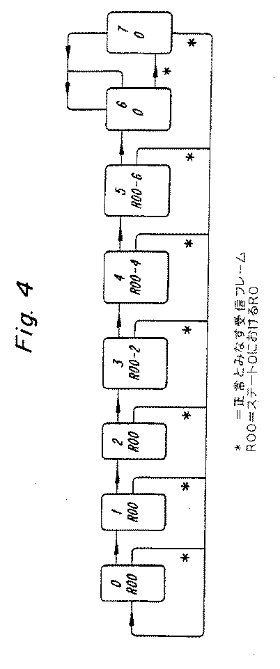
不良フレームのマスキング技術を行う1つの方法は、これを第4図に示すステート・マシンにより8つのステートと組み合わせることである。このステートはフレーム毎に更新される。ここで、第4図及び第5図を参照して、ステート・マシンを実行する本発明の特定の実施形態を説明する。 One way to perform bad frame masking techniques is to combine this with the eight states by the state machine shown in FIG. This state is updated every frame. A specific embodiment of the present invention for executing a state machine will now be described with reference to FIGS.
通常のステートはステート0である。受信した情報が不良、即ち、(1)CRCチェック・サムが正しくない、又は(2)ソフト品質値がしきい値Q1より低い(第5図を参照)、又は(3)フレームがFACCHデータからなるとみなされるときは、ステート・マシンは次のステートに進む。この応用に用いられるように、品質値は、ブロック、パラメータ又はビットの受信品質を反映させている測定値を意味する。ソフト品質値はQ1より高く、かつQ3より低いときは、着信フレーム・データは最後に受け入れたフレームにより補間される(第5図を参照)。しかし、補間されたフレームが正常とみなされ、また音声デコーダはステート0に留まる。
The normal state is
正常フレームが不良フレームの後に受信されるときは、ステート・マシンはステート0に戻り、そうでないときはステート・マシンは次のステートに進む。
When a normal frame is received after a bad frame, the state machine returns to
連続する6フレームが不良とみなされたときは、ステート・マシンはステート6になる。ステート0に戻るためには、1フレームが正常とみなされたとしなければならない。
When six consecutive frames are considered bad, the state machine goes to
ステート・マシンがどのステートにあるかに従って異なる措置がとられる。即ち、
ステート0では、何も措置を取らない。
ステート1では、受信したフレーム・パラメータ(RC及びLPC1〜LPC10)を、正常な前フレームのパラメータで置換する。
ステート2では、ステート1と同一の措置をとる。
ステート3では、フレーム・パラメータの置換を再び行う。更に、R0の値を2により減少させ、これがフレーム・エネルギを4dB減衰させる結果となる。
ステート4では、置換を再び行い、かつR0を再び2により減少させる。
ステート5では、ステート4と同一の措置をとる。ステート6では、R0は、無音声信号を聞くことを意味する値0にセットされる。
ステート7では、R0は0にセットされたままとなる。
Different actions are taken depending on which state the state machine is in. That is,
In
In
In
In
In
In
In state 7, R0 remains set to zero.
以上、説明したように、第4図のステート・マシンは本発明の特定の一実施を表すものに過ぎず、本発明は第4図及び第5図に示す構成に限定されるものではない。
本発明をその好ましい実施例により説明したが、使用した用語は説明のためのものにすぎず、本発明の真の範囲及び主旨を逸脱しない範囲で、その最も広い観点から、請求の範囲内で変更しうるものである。
As described above, the state machine of FIG. 4 represents only one specific implementation of the present invention, and the present invention is not limited to the configurations shown in FIGS.
Although the invention has been described in terms of its preferred embodiments, the terminology used is for illustration only and is within the scope of the claims from its broadest scope without departing from the true scope and spirit of the invention. It can be changed.
Claims (20)
現音声フレーム内の前記選択したパラメータの値と、現音声フレーム内の前記選択したパラメータが正しく受信されたことの信頼度を示す、現音声フレームの品質値と、を取得する第1取得ステップと、
前記少なくとも1つの前音声フレーム内の前記選択したパラメータの値と、前記少なくとも1つの前音声フレーム内の前記選択したパラメータが正しく受信されたことの信頼度を示す、前記少なくとも1つの前音声フレームの品質値と、を取得する第2取得ステップと、
現音声フレーム内の前記選択したパラメータの値と前記少なくとも1つの前音声フレーム内の前記選択したパラメータの値との重み付け和を用いて、現音声フレームの前記選択したパラメータの補間パラメータ値を計算する計算ステップと、
を有し、
現音声フレーム内の前記選択したパラメータの値に適用される重みは、現音声フレームの前記品質値に応じて設定されることを特徴とする方法。 A wireless receiver receives, demodulates, and channel decodes, respectively, first audio data corresponding to at least one previous audio frame and second audio data corresponding to a current audio frame, and said at least one In a TDMA radio system configured to generate a previous speech frame and a current speech frame, a method for improving the quality of a current speech frame by determining an interpolation parameter value of a selected parameter in the current speech frame,
A first obtaining step of obtaining a value of the selected parameter in the current speech frame and a quality value of the current speech frame that indicates a confidence that the selected parameter in the current speech frame has been correctly received; ,
The value of the selected parameter in the at least one previous speech frame and the at least one previous speech frame indicating a confidence that the selected parameter in the at least one previous speech frame was received correctly. A second acquisition step of acquiring a quality value;
An interpolation parameter value for the selected parameter of the current speech frame is calculated using a weighted sum of the value of the selected parameter in the current speech frame and the value of the selected parameter in the at least one previous speech frame. A calculation step;
Have
The method is characterized in that the weight applied to the value of the selected parameter in the current speech frame is set according to the quality value of the current speech frame.
チャネルに符号化された信号を受信する受信手段と、
受信した前記信号を復調する復調手段と、
復調されたチャネルを現音声フレーム及び少なくとも1つの前音声フレームに復号化する復号化手段と、
現音声フレームの品質を改善させる改善手段と、
を有し、
前記改善手段は、
現音声フレーム内の前記選択したパラメータの値と、現音声フレーム内の前記選択したパラメータが正しく受信されたことの信頼度を示す、現音声フレームの品質値と、を取得する第1取得手段と、
前記少なくとも1つの前音声フレーム内の前記選択したパラメータの値と、前記少なくとも1つの前音声フレーム内の前記選択したパラメータが正しく受信されたことの信頼度を示す、前記少なくとも1つの前音声フレームの品質値と、を取得する第2取得手段と、
現音声フレーム内の前記選択したパラメータの値と前記少なくとも1つの前音声フレーム内の前記選択したパラメータの値との重み付け和を用いて、現音声フレームの前記選択したパラメータの補間パラメータ値を計算する計算手段と、
を有し、
現音声フレーム内の前記選択したパラメータの値に適用される重みは、現音声フレームの前記品質値に応じて設定されることを特徴とする無線システム。 A wireless system for receiving and processing TDMA signals,
Receiving means for receiving a signal encoded in the channel;
Demodulation means for demodulating the received signal;
Decoding means for decoding the demodulated channel into a current voice frame and at least one previous voice frame;
Improvement means to improve the quality of the current voice frame;
Have
The improvement means is
First acquisition means for acquiring a value of the selected parameter in the current voice frame and a quality value of the current voice frame that indicates a reliability that the selected parameter in the current voice frame has been correctly received; ,
The value of the selected parameter in the at least one previous speech frame and the at least one previous speech frame indicating a confidence that the selected parameter in the at least one previous speech frame was received correctly. A second acquisition means for acquiring a quality value;
An interpolation parameter value for the selected parameter of the current speech frame is calculated using a weighted sum of the value of the selected parameter in the current speech frame and the value of the selected parameter in the at least one previous speech frame. A calculation means;
Have
A wireless system, wherein a weight applied to the value of the selected parameter in a current voice frame is set according to the quality value of the current voice frame.
Applications Claiming Priority (1)
| Application Number | Priority Date | Filing Date | Title |
|---|---|---|---|
| US08/162,605 US5502713A (en) | 1993-12-07 | 1993-12-07 | Soft error concealment in a TDMA radio system |
Related Parent Applications (1)
| Application Number | Title | Priority Date | Filing Date |
|---|---|---|---|
| JP51613795A Division JP3943127B2 (en) | 1993-12-07 | 1994-12-01 | Soft error correction in TDMA wireless systems |
Publications (2)
| Publication Number | Publication Date |
|---|---|
| JP2007166650A JP2007166650A (en) | 2007-06-28 |
| JP4199281B2 true JP4199281B2 (en) | 2008-12-17 |
Family
ID=22586362
Family Applications (2)
| Application Number | Title | Priority Date | Filing Date |
|---|---|---|---|
| JP51613795A Expired - Lifetime JP3943127B2 (en) | 1993-12-07 | 1994-12-01 | Soft error correction in TDMA wireless systems |
| JP2007002867A Expired - Lifetime JP4199281B2 (en) | 1993-12-07 | 2007-01-10 | Soft error correction in TDMA wireless systems |
Family Applications Before (1)
| Application Number | Title | Priority Date | Filing Date |
|---|---|---|---|
| JP51613795A Expired - Lifetime JP3943127B2 (en) | 1993-12-07 | 1994-12-01 | Soft error correction in TDMA wireless systems |
Country Status (13)
| Country | Link |
|---|---|
| US (1) | US5502713A (en) |
| EP (1) | EP0682831A1 (en) |
| JP (2) | JP3943127B2 (en) |
| KR (1) | KR100344513B1 (en) |
| CN (1) | CN1153399C (en) |
| AU (1) | AU678667B2 (en) |
| CA (1) | CA2154253A1 (en) |
| FI (1) | FI953707A (en) |
| MY (1) | MY112120A (en) |
| RU (1) | RU2130693C1 (en) |
| SG (1) | SG49995A1 (en) |
| TW (1) | TW269081B (en) |
| WO (1) | WO1995016315A1 (en) |
Families Citing this family (47)
| Publication number | Priority date | Publication date | Assignee | Title |
|---|---|---|---|---|
| SE501340C2 (en) * | 1993-06-11 | 1995-01-23 | Ericsson Telefon Ab L M | Hiding transmission errors in a speech decoder |
| FI96259C (en) * | 1994-03-28 | 1996-05-27 | Nokia Telecommunications Oy | decoding method |
| US5768291A (en) * | 1994-12-29 | 1998-06-16 | Motorola, Inc. | Method and apparatus for error mitigating a received communication signal |
| US5726978A (en) * | 1995-06-22 | 1998-03-10 | Telefonaktiebolaget L M Ericsson Publ. | Adaptive channel allocation in a frequency division multiplexed system |
| US5862190A (en) * | 1995-12-29 | 1999-01-19 | Motorola, Inc. | Method and apparatus for decoding an encoded signal |
| FI100566B (en) * | 1996-01-24 | 1997-12-31 | Nokia Telecommunications Oy | Frame quality identification method and receiver |
| SE506341C2 (en) * | 1996-04-10 | 1997-12-08 | Ericsson Telefon Ab L M | Method and apparatus for reconstructing a received speech signal |
| JP3340618B2 (en) * | 1996-04-19 | 2002-11-05 | 松下電器産業株式会社 | Error detection method |
| US5960010A (en) * | 1996-05-03 | 1999-09-28 | Texas Instruments Incorporated | Error detection and error concealment of convolutionally encoded data |
| WO1997043835A1 (en) * | 1996-05-15 | 1997-11-20 | Seagate Technology, Inc. | Read error recovery utilizing ecc and read channel quality indicators |
| US5802076A (en) * | 1996-05-24 | 1998-09-01 | National Semiconductor Corporation | Audio error mitigation technique for a TDMA communication system |
| FR2751813B1 (en) * | 1996-07-29 | 1999-01-08 | Alcatel Mobile Comm France | METHOD AND DEVICE FOR ESTIMATING THE ACCEPTABLE OR NON-ACCEPTABLE NATURE OF INFORMATION BLOCKS RECEIVED VIA A TRANSMISSION SYSTEM USING BLOCK CODING |
| DE19716147A1 (en) | 1997-04-17 | 1998-10-22 | Alsthom Cge Alcatel | Method and device for fault concealment in digital transmission systems |
| SE511310C2 (en) | 1997-05-20 | 1999-09-06 | Ericsson Telefon Ab L M | Method for bit detection in a radio communication system |
| US5936972A (en) * | 1997-06-18 | 1999-08-10 | Motorola, Inc. | Syndrome-based channel quality or message structure determiner |
| FI103235B (en) * | 1997-06-26 | 1999-05-14 | Nokia Telecommunications Oy | Interference suppression method in OFDM radio receiver |
| US6252731B1 (en) | 1997-10-16 | 2001-06-26 | Seagate Technology Llc | Parametric optimization using disc drive read channel quality measurements |
| JP3177957B2 (en) * | 1998-01-28 | 2001-06-18 | 日本電気株式会社 | Demodulation circuit including error correction |
| US6810377B1 (en) * | 1998-06-19 | 2004-10-26 | Comsat Corporation | Lost frame recovery techniques for parametric, LPC-based speech coding systems |
| US6392833B1 (en) | 1998-07-13 | 2002-05-21 | Seagate Technology, Llc | Reducing self-excited mechanical resonances in a disc drive |
| US6188980B1 (en) | 1998-08-24 | 2001-02-13 | Conexant Systems, Inc. | Synchronized encoder-decoder frame concealment using speech coding parameters including line spectral frequencies and filter coefficients |
| US6256487B1 (en) | 1998-09-01 | 2001-07-03 | Telefonaktiebolaget Lm Ericsson (Publ) | Multiple mode transmitter using multiple speech/channel coding modes wherein the coding mode is conveyed to the receiver with the transmitted signal |
| US6366624B1 (en) * | 1998-11-30 | 2002-04-02 | Ericsson Inc. | Systems and methods for receiving a modulated signal containing encoded and unencoded bits using multi-pass demodulation |
| JP2000305599A (en) | 1999-04-22 | 2000-11-02 | Sony Corp | Speech synthesizing device and method, telephone device, and program providing media |
| DE19921504A1 (en) * | 1999-05-10 | 2000-11-23 | Alcatel Sa | Method and circuit arrangement for determining quality information about the transmission quality of a speech signal in a digital transmission system |
| DE19932943A1 (en) * | 1999-07-14 | 2001-01-18 | Siemens Ag | Method and device for decoding source signals |
| FR2797125B1 (en) * | 1999-07-26 | 2001-10-05 | Matra Nortel Communications | METHOD AND DEVICE FOR FORMING TRANSPORT FRAMES FROM CODE SIGNAL FRAMES, AND DEVICE FOR EXTRACTING SIGNAL CODE FRAMES |
| US6208699B1 (en) * | 1999-09-01 | 2001-03-27 | Qualcomm Incorporated | Method and apparatus for detecting zero rate frames in a communications system |
| US6636829B1 (en) * | 1999-09-22 | 2003-10-21 | Mindspeed Technologies, Inc. | Speech communication system and method for handling lost frames |
| EP1238488B1 (en) * | 1999-12-09 | 2007-02-28 | Nokia Corporation | Mobile equipment based filtering for packet radio service applications |
| AU5677200A (en) * | 2000-05-29 | 2001-12-11 | Telefonaktiebolaget Lm Ericsson (Publ) | Error detection and error concealment for encoded speech data |
| FI118242B (en) * | 2000-09-19 | 2007-08-31 | Nokia Corp | Management of speech frames in a radio system |
| US7031926B2 (en) * | 2000-10-23 | 2006-04-18 | Nokia Corporation | Spectral parameter substitution for the frame error concealment in a speech decoder |
| US7274755B2 (en) * | 2000-12-18 | 2007-09-25 | Infineon Technologies Ag | Receiver |
| US20020108090A1 (en) * | 2001-02-05 | 2002-08-08 | Cute Ltd. | Blind transport format detection of turbo-coded data |
| US6732321B2 (en) * | 2001-03-27 | 2004-05-04 | Motorola, Inc. | Method, apparatus, and article of manufacture for error detection and channel management in a communication system |
| US7209712B2 (en) * | 2002-09-23 | 2007-04-24 | Qualcomm, Incorporated | Mean square estimation of channel quality measure |
| GB2398982B (en) * | 2003-02-27 | 2005-05-18 | Motorola Inc | Speech communication unit and method for synthesising speech therein |
| US7409338B1 (en) | 2004-11-10 | 2008-08-05 | Mediatek Incorporation | Softbit speech decoder and related method for performing speech loss concealment |
| US7877253B2 (en) | 2006-10-06 | 2011-01-25 | Qualcomm Incorporated | Systems, methods, and apparatus for frame erasure recovery |
| KR100862662B1 (en) | 2006-11-28 | 2008-10-10 | 삼성전자주식회사 | Method and Apparatus of Frame Error Concealment, Method and Apparatus of Decoding Audio using it |
| EP2071852A1 (en) | 2007-12-11 | 2009-06-17 | Alcatel Lucent | Process for delivering a video stream over a wireless bidirectional channel between a video encoder and a video decoder |
| EP2071851B1 (en) * | 2007-12-11 | 2011-09-28 | Alcatel Lucent | Process for delivering a video stream over a wireless channel |
| KR20140067512A (en) * | 2012-11-26 | 2014-06-05 | 삼성전자주식회사 | Signal processing apparatus and signal processing method thereof |
| US9336789B2 (en) * | 2013-02-21 | 2016-05-10 | Qualcomm Incorporated | Systems and methods for determining an interpolation factor set for synthesizing a speech signal |
| EP2830054A1 (en) | 2013-07-22 | 2015-01-28 | Fraunhofer Gesellschaft zur Förderung der angewandten Forschung e.V. | Audio encoder, audio decoder and related methods using two-channel processing within an intelligent gap filling framework |
| CN111224677B (en) * | 2018-11-27 | 2021-10-15 | 华为技术有限公司 | Encoding method, decoding method and device |
Family Cites Families (6)
| Publication number | Priority date | Publication date | Assignee | Title |
|---|---|---|---|---|
| JPS61102841A (en) * | 1984-10-24 | 1986-05-21 | Nec Corp | Line quality monitoring device |
| GB2182529A (en) * | 1985-10-30 | 1987-05-13 | Philips Electronic Associated | Digital communication of analogue signals |
| JPH02299324A (en) * | 1989-05-15 | 1990-12-11 | Mitsubishi Electric Corp | Vocoder |
| JP2591242B2 (en) * | 1990-04-02 | 1997-03-19 | 松下電器産業株式会社 | Error detection method |
| JP3102015B2 (en) * | 1990-05-28 | 2000-10-23 | 日本電気株式会社 | Audio decoding method |
| JP2748743B2 (en) * | 1991-10-01 | 1998-05-13 | 日本電気株式会社 | Data receiving method |
-
1993
- 1993-12-07 US US08/162,605 patent/US5502713A/en not_active Expired - Lifetime
-
1994
- 1994-11-15 TW TW083110550A patent/TW269081B/zh active
- 1994-11-29 MY MYPI94003185A patent/MY112120A/en unknown
- 1994-12-01 WO PCT/SE1994/001157 patent/WO1995016315A1/en not_active Application Discontinuation
- 1994-12-01 EP EP95903481A patent/EP0682831A1/en not_active Withdrawn
- 1994-12-01 AU AU12518/95A patent/AU678667B2/en not_active Expired
- 1994-12-01 CA CA002154253A patent/CA2154253A1/en not_active Abandoned
- 1994-12-01 RU RU95120398A patent/RU2130693C1/en active
- 1994-12-01 CN CNB941914046A patent/CN1153399C/en not_active Expired - Lifetime
- 1994-12-01 SG SG1996012113A patent/SG49995A1/en unknown
- 1994-12-01 KR KR1019950703250A patent/KR100344513B1/en not_active IP Right Cessation
- 1994-12-01 JP JP51613795A patent/JP3943127B2/en not_active Expired - Lifetime
-
1995
- 1995-08-03 FI FI953707A patent/FI953707A/en unknown
-
2007
- 2007-01-10 JP JP2007002867A patent/JP4199281B2/en not_active Expired - Lifetime
Also Published As
| Publication number | Publication date |
|---|---|
| TW269081B (en) | 1996-01-21 |
| CN1153399C (en) | 2004-06-09 |
| CA2154253A1 (en) | 1995-06-15 |
| FI953707A0 (en) | 1995-08-03 |
| JP3943127B2 (en) | 2007-07-11 |
| AU1251895A (en) | 1995-06-27 |
| EP0682831A1 (en) | 1995-11-22 |
| KR100344513B1 (en) | 2002-12-06 |
| US5502713A (en) | 1996-03-26 |
| JP2007166650A (en) | 2007-06-28 |
| WO1995016315A1 (en) | 1995-06-15 |
| SG49995A1 (en) | 1998-06-15 |
| AU678667B2 (en) | 1997-06-05 |
| CN1119058A (en) | 1996-03-20 |
| FI953707A (en) | 1995-08-03 |
| RU2130693C1 (en) | 1999-05-20 |
| JPH08508866A (en) | 1996-09-17 |
| MY112120A (en) | 2001-04-30 |
| KR960701536A (en) | 1996-02-24 |
Similar Documents
| Publication | Publication Date | Title |
|---|---|---|
| JP4199281B2 (en) | Soft error correction in TDMA wireless systems | |
| RU2239950C2 (en) | Method for encoding modes of codec operation with use of a priori knowledge | |
| US6170073B1 (en) | Method and apparatus for error detection in digital communications | |
| US7616712B2 (en) | Systems and methods for detecting discontinuous transmission (DTX) using cyclic redundancy check results to modify preliminary DTX classification | |
| JP4094678B2 (en) | Information encoding method and apparatus using error correction and error detection | |
| EP0910066A2 (en) | Coding method and apparatus, and decoding method and apparatus | |
| KR20010085425A (en) | Data transmission method, data transmission system, sending device and receiving device | |
| GB2311699A (en) | Encoding and decoding for digital communications | |
| KR100213876B1 (en) | Bits error rate measuring device using viterbi decoder | |
| US6714896B1 (en) | Method and apparatus for signal degradation measurement | |
| US6004028A (en) | Device and method for receiving and reconstructing signals with improved perceived signal quality | |
| JP3265339B2 (en) | Audio decoding device | |
| EP0983655B1 (en) | Bit detection method in a radio communications system | |
| JP2008054235A (en) | Modulation method decision unit, receiver, modulation method decision method, and modulation method decision program | |
| JP2002501328A (en) | Method and apparatus for coding, decoding and transmitting information using source control channel decoding | |
| US20030101386A1 (en) | Method for detecting errors in a real-time data entity comprising at least two bit protions having different relevance and corresponding receiver | |
| JP2001339466A (en) | Variable-rate code receiving device | |
| JP2000196568A (en) | Adpcm correction system | |
| JP2000244460A (en) | Transmission line error code addition and detecting device | |
| MXPA01002141A (en) | Codec mode decoding using a priori knowledge | |
| JPH11243376A (en) | Sound decoding device |
Legal Events
| Date | Code | Title | Description |
|---|---|---|---|
| A131 | Notification of reasons for refusal |
Free format text: JAPANESE INTERMEDIATE CODE: A131 Effective date: 20070622 |
|
| A601 | Written request for extension of time |
Free format text: JAPANESE INTERMEDIATE CODE: A601 Effective date: 20070919 |
|
| A602 | Written permission of extension of time |
Free format text: JAPANESE INTERMEDIATE CODE: A602 Effective date: 20070927 |
|
| A521 | Request for written amendment filed |
Free format text: JAPANESE INTERMEDIATE CODE: A523 Effective date: 20071022 |
|
| A131 | Notification of reasons for refusal |
Free format text: JAPANESE INTERMEDIATE CODE: A131 Effective date: 20071207 |
|
| A521 | Request for written amendment filed |
Free format text: JAPANESE INTERMEDIATE CODE: A523 Effective date: 20080225 |
|
| A131 | Notification of reasons for refusal |
Free format text: JAPANESE INTERMEDIATE CODE: A131 Effective date: 20080328 |
|
| A521 | Request for written amendment filed |
Free format text: JAPANESE INTERMEDIATE CODE: A523 Effective date: 20080623 |
|
| A521 | Request for written amendment filed |
Free format text: JAPANESE INTERMEDIATE CODE: A523 Effective date: 20080626 |
|
| TRDD | Decision of grant or rejection written | ||
| A01 | Written decision to grant a patent or to grant a registration (utility model) |
Free format text: JAPANESE INTERMEDIATE CODE: A01 Effective date: 20080905 |
|
| A01 | Written decision to grant a patent or to grant a registration (utility model) |
Free format text: JAPANESE INTERMEDIATE CODE: A01 |
|
| A61 | First payment of annual fees (during grant procedure) |
Free format text: JAPANESE INTERMEDIATE CODE: A61 Effective date: 20081002 |
|
| FPAY | Renewal fee payment (event date is renewal date of database) |
Free format text: PAYMENT UNTIL: 20111010 Year of fee payment: 3 |
|
| R150 | Certificate of patent or registration of utility model |
Free format text: JAPANESE INTERMEDIATE CODE: R150 |
|
| FPAY | Renewal fee payment (event date is renewal date of database) |
Free format text: PAYMENT UNTIL: 20121010 Year of fee payment: 4 |
|
| FPAY | Renewal fee payment (event date is renewal date of database) |
Free format text: PAYMENT UNTIL: 20131010 Year of fee payment: 5 |
|
| R250 | Receipt of annual fees |
Free format text: JAPANESE INTERMEDIATE CODE: R250 |
|
| R250 | Receipt of annual fees |
Free format text: JAPANESE INTERMEDIATE CODE: R250 |
|
| EXPY | Cancellation because of completion of term |