JP2010054439A - Flow line measuring system - Google Patents
Flow line measuring system Download PDFInfo
- Publication number
- JP2010054439A JP2010054439A JP2008221825A JP2008221825A JP2010054439A JP 2010054439 A JP2010054439 A JP 2010054439A JP 2008221825 A JP2008221825 A JP 2008221825A JP 2008221825 A JP2008221825 A JP 2008221825A JP 2010054439 A JP2010054439 A JP 2010054439A
- Authority
- JP
- Japan
- Prior art keywords
- sensor
- ultrasonic
- sensors
- sound source
- ultrasonic wave
- Prior art date
- Legal status (The legal status is an assumption and is not a legal conclusion. Google has not performed a legal analysis and makes no representation as to the accuracy of the status listed.)
- Granted
Links
Images


Landscapes
- Measurement Of Velocity Or Position Using Acoustic Or Ultrasonic Waves (AREA)
Abstract
Description
本発明は、超音波を利用して検出対象の移動体の位置を追跡する動線計測システムに関する。 The present invention relates to a flow line measurement system that uses ultrasonic waves to track the position of a moving object to be detected.
従来より、例えば下記特許文献1に示すように、位置検出対象の移動体に搭載され超音波を発生可能な音源と、音源から送波された超音波を受波し電気信号に変換する複数個の受波素子が同一基板上に配列された超音波アレイセンサとを備え、超音波アレイセンサの各受波素子で超音波を受波した時間の時間差と各受波素子の配置位置とに基づいて移動体が存在する方位を求める動線計測システムが提案されている。
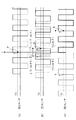
図9は、従来の超音波アレイセンサの基板上に配列されたセンサA〜Cの位置関係を示す図であり、センサAとCの間は距離dを空けて配置されている。図9では、センサA〜Cが配置された面と垂直な方向から左寄りに角度θだけ回転した位置に音源がある。音源までの距離は、センサA〜C間の距離と比較して十分遠くにあるので、図9において、超音波91〜93はほぼ平行に入射していると考えることができる。
FIG. 9 is a diagram showing a positional relationship between sensors A to C arranged on a substrate of a conventional ultrasonic array sensor, and the sensors A and C are arranged with a distance d. In FIG. 9, there is a sound source at a position rotated by an angle θ from the direction perpendicular to the plane on which the sensors A to C are arranged to the left. Since the distance to the sound source is sufficiently far compared with the distance between the sensors A to C, it can be considered that the
超音波91〜93は、センサA〜Cの配置面に対して入射角θの角度で入射するため、例えば超音波93がセンサCに到達する時間は、超音波91がセンサAに到達する時間と比較すると、入射角θに依存した時間だけ遅れることとなる。センサAとCの音源までの距離の差は、dsin θの式で求めることができるから、音波速度をν(約340m/s)とすると、センサAとCの超音波の到達時間の差tは、t=dsin θ/νの式で求めることができる。
Since the
図10〜図11は、図9のアレイセンサに、特許文献1の動線計測システムにおいて音源として利用されている熱励起式の超音波発生素子から送波された超音波を受波させた場合における受波信号の波形を示したものである。何れの図も、(a)がセンサAの受波信号、(b)がセンサBの受波信号、(c)がセンサCの受波信号を示している。
10 to 11 show the case where the array sensor of FIG. 9 receives the ultrasonic wave transmitted from the thermal excitation type ultrasonic wave generation element used as the sound source in the flow line measurement system of
熱励起式の超音波発生素子は、発熱体層の両端のパッド間に通電して発熱体層に温度変化を生じさせて超音波を発生させるので、発熱体層への通電を適宜に制御することで発生させる超音波の周波数を広範囲にわたって変化させることができる。図11では残響時間が若干長くなっているが、図10に示すような略1周期の超音波を発生させることもできる。 The thermal excitation type ultrasonic wave generating element energizes between the pads at both ends of the heating element layer to cause a temperature change in the heating element layer to generate ultrasonic waves, so that the energization to the heating element layer is appropriately controlled. Thus, the frequency of the ultrasonic wave generated can be changed over a wide range. In FIG. 11, the reverberation time is slightly longer, but it is also possible to generate an ultrasonic wave of approximately one cycle as shown in FIG.
センサA〜Cの受波信号は、図10〜図11に示すように同じ時間軸上に表示すると、一定の時間遅れを有するものとなる。そこで、例えば図10に示すように各波形の最初の立ち上がりに注目すると、立ち上がりの波形はセンサA、B、Cの順に一定時間分だけ遅延した位置に表れる。そして、図10における時間差tは、t=dsin θ/νの計算式で求められるものであるため、逆に、各センサの受波時間の差が分かれば、音源がどの方向に存在するか(入射角θの値)を知ることができる。特許文献1の動線計測システムは、このような方式により移動体の位置を追跡するものである。
When the received signals of the sensors A to C are displayed on the same time axis as shown in FIGS. 10 to 11, they have a certain time delay. Therefore, for example, as shown in FIG. 10, when attention is paid to the first rise of each waveform, the rise waveform appears at a position delayed by a predetermined time in the order of the sensors A, B, and C. Since the time difference t in FIG. 10 is obtained by the calculation formula of t = dsin θ / ν, conversely, if the difference in the reception time of each sensor is known, in which direction the sound source exists ( The value of the incident angle θ). The flow line measurement system of
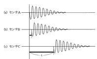
ところで、特許文献1では、例えば図10に示すような、最初の立ち上りの波形が大きく明確に表れる熱励起式の超音波発生素子を使用しているが、一般に市販されている圧電セラミックス素子(例えば村田製作所製のピエゾタイト(登録商標)等)を超音波発生素子として使用する場合、音圧を上げるため素子への電圧印加を交流電圧のように複数サイクル繰り返し印加する。このため、センサA〜Cの受波信号は、図12に示すように、最初の立ち上り(第1波)は極めて小さく、その後徐々に大きくなって例えば第7〜第10波目に最大になるという性質がある。
By the way, in
そのため、第1波を検出するためには各センサの閾値を低いレベルに設定する必要があるが、閾値を低く設定するとセンサの感度が低下し、図12(b)に示すように、第1波を検出できずに第2波E1を誤検出したり、受波信号ではないノイズを拾ってしまう場合がある。 Therefore, in order to detect the first wave, it is necessary to set the threshold value of each sensor to a low level. However, if the threshold value is set to be low, the sensitivity of the sensor decreases, and as shown in FIG. In some cases, the second wave E1 may be erroneously detected without detecting a wave, or noise that is not a received signal may be picked up.
また、例えば図13(a)に示すように、第4波を検出できるように閾値を高めに設定しても、センサによっては波形に歪がある場合があるため、図13(b)に示すように、第5波E2を検出し、半波長のずれが生じて検出誤差を生じる場合がある。 For example, as shown in FIG. 13 (a), even if the threshold is set high so that the fourth wave can be detected, the waveform may be distorted depending on the sensor. As described above, the fifth wave E2 is detected, and there is a case where a half-wavelength shift occurs and a detection error occurs.
本発明は、上記した従来の問題点に鑑みてなされたものであり、受波信号の最初の立ち上り(第1波)が大きく明確に表れる熱励起式の超音波発生素子ではなく、一般に市販されている圧電式の超音波発生素子を使用した場合でも、受波信号の誤検出を可及的に防止することができる動線計測システムを提供することを目的としている。 The present invention has been made in view of the above-described conventional problems, and is not a thermal excitation type ultrasonic wave generating element in which the first rising edge (first wave) of a received signal appears largely and clearly, and is generally commercially available. It is an object of the present invention to provide a flow line measurement system capable of preventing erroneous detection of a received signal as much as possible even when a piezoelectric ultrasonic wave generating element is used.
解決しようとする課題は、受波信号の最初の立ち上り(第1波)が小さく、その後徐々に大きくなる性質を有する圧電式の超音波発生素子を使用した場合でも、受波信号の誤検出を可及的に防止する点である。 The problem to be solved is that erroneous detection of a received signal is caused even when a piezoelectric ultrasonic wave generating element having the property that the initial rise (first wave) of the received signal is small and then gradually increases is used. It is a point to prevent as much as possible.
上記の問題点を解決するため、本発明の動線計測システムは、
超音波を発生可能な音源と、前記音源から送波された超音波を受波し電気信号である受波信号に変換する複数個のセンサが同一基板上に二次元的に配列されたアレイセンサと、前記受波信号を解析する制御部と、を備え、前記音源、前記アレイセンサのうち何れか一方を位置検出対象の移動体に搭載し、他方を所定の位置に配置した動線計測システムであって、
前記アレイセンサは、前記基板上の左右方向とこれに直交する上下方向に第1、第2及び第3センサを夫々直線状に配列し、かつ、前記音源から発生させる超音波の波長をλとするとき、前記第2センサは前記第1センサからλ/2以下の間隔Lで配置するとともに、前記第3センサは前記第1センサからn×λ(nは自然数)の間隔で配置し、
前記制御部は、前記第2センサと前記第1センサの受波時間の差をn×λ/L倍して前記第3センサの受波時間の予測値を求める予測手段と、前記第3センサにおいて前記予測値から所定の時間範囲内に検出された受波信号のみを正しい信号として採用する確認手段とを備え、
前記確認手段により正しい信号と確認された第3センサの受波信号の受波時間と前記第1センサの受波時間の差と、前記第1、第3センサ間の距離に基づいて、前記音源から送波された超音波の入射角を求め、前記移動体の位置情報を検出することを最も主要な特徴点としている。
In order to solve the above problems, the flow line measurement system of the present invention is:
An array sensor in which a sound source capable of generating an ultrasonic wave and a plurality of sensors that receive the ultrasonic wave transmitted from the sound source and convert it into a received signal that is an electric signal are two-dimensionally arranged on the same substrate And a control unit that analyzes the received signal, a flow line measuring system in which one of the sound source and the array sensor is mounted on a position detection target moving body, and the other is disposed at a predetermined position. Because
In the array sensor, first, second, and third sensors are linearly arranged in a horizontal direction on the substrate and a vertical direction perpendicular thereto, and the wavelength of the ultrasonic wave generated from the sound source is λ. The second sensor is arranged at an interval L of λ / 2 or less from the first sensor, and the third sensor is arranged at an interval of n × λ (n is a natural number) from the first sensor,
The control unit is configured to calculate a predicted value of the reception time of the third sensor by multiplying a difference between reception times of the second sensor and the first sensor by n × λ / L, and the third sensor And a confirmation means that adopts only a received signal detected within a predetermined time range from the predicted value as a correct signal,
The sound source is based on the difference between the reception time of the reception signal of the third sensor and the reception time of the first sensor, which is confirmed as a correct signal by the confirmation means, and the distance between the first and third sensors. The most important feature point is to obtain the incident angle of the ultrasonic wave transmitted from, and detect the position information of the moving body.
本発明によれば、熱励起式の超音波発生素子ではなく、受波信号が徐々に大きくなる圧電式の超音波発生素子を使用した場合でも、受波信号の誤検出を可及的に防止することができる。 According to the present invention, erroneous detection of a received signal is prevented as much as possible even when a piezoelectric ultrasonic generating element whose received signal gradually increases is used instead of a thermal excitation type ultrasonic generating element. can do.
本発明において、アレイセンサの基板上に配列したセンサ間の距離を上記のように特定した理由は以下の点にある。 In the present invention, the reason why the distance between the sensors arranged on the substrate of the array sensor is specified as described above is as follows.
熱励起式の超音波発生素子を使用した場合は、受波信号の最初の立ち上り(第1波)が大きく明確に表れるから、第1波を確実に検出することができ、第2波以降を誤検出するおそれがない。しかし、圧電式の超音波発生素子を利用する場合は、共振特性のQ値が大きく残響を伴い、音圧を上げるため素子への電圧印加を交流電圧のように複数サイクル繰り返し印加するため、第1波ではなく第7〜第10波が最大値となることもある。つまり、圧電式の超音波発生素子を利用する場合は、第1波が最大とは限らず、センサの閾値を越えた波形(仮に「第n波」とする。)を検出したとき、その前後の波形(第n+1波または第n−1波)も第n波と同程度の大きさの信号である可能性がある。そうすると、センサ間の距離がλ/2(λは超音波の波長)よりも大きいと、入射角θが0°以上のプラス側の角度で第n波を検出しているのか、入射角θが0°以下のマイナス側の角度で第n+1波を検出しているのかを判別することが困難である。そこで、本発明では、先ずは、第2センサを第1のセンサからλ/2以下の間隔の位置に配置し、いかなる入射角θに対しても第n+1波や第n−1波を誤検出するおそれを無くすようにした。 When a thermal excitation type ultrasonic wave generating element is used, the first rising edge (first wave) of the received signal appears large and clearly, so that the first wave can be reliably detected, and the second wave and thereafter are detected. There is no risk of false detection. However, when a piezoelectric ultrasonic wave generating element is used, since the Q value of the resonance characteristics is large and reverberation is applied, voltage application to the element is repeatedly applied for a plurality of cycles like an AC voltage in order to increase sound pressure. The seventh to tenth waves may become the maximum value instead of one wave. That is, when a piezoelectric ultrasonic wave generating element is used, the first wave is not always the maximum, and when a waveform exceeding the sensor threshold value (assumed to be “the nth wave”) is detected, before and after that. The waveform (n + 1 wave or n-1 wave) may also be a signal having the same magnitude as the nth wave. Then, if the distance between the sensors is larger than λ / 2 (λ is the wavelength of the ultrasonic wave), whether the incident angle θ is detected at a positive angle of 0 ° or more, or the incident angle θ is It is difficult to determine whether the (n + 1) th wave is detected at a minus side angle of 0 ° or less. Therefore, in the present invention, first, the second sensor is disposed at a position of λ / 2 or less from the first sensor, and the n + 1-th wave and the n-1-th wave are erroneously detected for any incident angle θ. The risk of doing so was eliminated.
しかしながら、センサ間の距離をλ/2以下とする場合は、超音波が各センサに到達する時間の時間差が極めて小さくなり、当該時間差から入射角を精度良く検出することが困難となる。そこで、本発明では、第3センサを第1センサからn×λ(nは自然数)の間隔を空けた位置に配置した。さらに、本発明では、アレイセンサから出力される受波信号を解析する制御部に、第2センサと第1センサの受波時間の差をn×λ/L倍して第3センサの受波時間の予測値を求める予測手段と、第3センサにおいて前記予測値から所定の時間範囲内に検出された受波信号のみを正しい信号として採用する確認手段を設けるようにした。 However, when the distance between the sensors is λ / 2 or less, the time difference between the times when the ultrasonic waves reach each sensor becomes extremely small, and it is difficult to accurately detect the incident angle from the time difference. Therefore, in the present invention, the third sensor is arranged at a position spaced by n × λ (n is a natural number) from the first sensor. Further, according to the present invention, the control unit for analyzing the received signal output from the array sensor is multiplied by n × λ / L by the difference between the reception times of the second sensor and the first sensor. Prediction means for obtaining a predicted value of time and confirmation means for adopting only a received signal detected within a predetermined time range from the predicted value by the third sensor as a correct signal are provided.
こうすることにより、本発明では、確認手段により正しい信号と確認された第3センサの受波信号の受波時間とそれに対応する第1センサの受波信号の受波時間の差、及び、第1センサと第3センサ間の距離に基づいて、音源から送波された超音波の入射角を求めることができる。 In this way, in the present invention, the difference between the reception time of the reception signal of the third sensor confirmed as a correct signal by the confirmation means and the reception time of the reception signal of the first sensor corresponding thereto, Based on the distance between the first sensor and the third sensor, the incident angle of the ultrasonic wave transmitted from the sound source can be obtained.
したがって、本発明では、各センサのノイズレベルよりも十分に高い任意の閾値を設定することにより、第1センサが閾値を越えた波形(第n波)を検出したとき、第2センサがその前後の波形(第n+1波または第n−1波)を誤検出するおそれが無く、しかも第1センサと第3センサの間には十分な時間差が得られるので、圧電式の超音波発生素子を利用する場合でも、一定の精度で受波信号を検出することが可能となる。 Therefore, in the present invention, by setting an arbitrary threshold value sufficiently higher than the noise level of each sensor, when the first sensor detects a waveform (n-th wave) exceeding the threshold value, the second sensor The waveform (n + 1 wave or n-1 wave) is not erroneously detected, and a sufficient time difference is obtained between the first sensor and the third sensor, so a piezoelectric ultrasonic generator is used. Even in this case, the received signal can be detected with a certain accuracy.
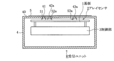
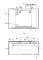
以下、本発明の実施形態の一例について、図1〜図8を用いて説明する。図1は、本実施例の動線計測システムの受信ユニットの構成を説明する断面図、図2はアレイセンサの基板上に配列した複数のセンサの位置関係を説明する図である。 Hereinafter, an example of an embodiment of the present invention will be described with reference to FIGS. FIG. 1 is a cross-sectional view for explaining the configuration of the receiving unit of the flow line measurement system of this embodiment, and FIG. 2 is a view for explaining the positional relationship between a plurality of sensors arranged on the substrate of the array sensor.
図1において、Rは受信ユニットであり、超音波を発生可能な音源から送波された超音波を受波するとともに受波した超音波を電気信号である受波信号に変換する複数個のセンサS1,S2a,S3aと、センサS2b,S3b(図1においては図示せず)が同一の基板1上に二次元的に配列されたアレイセンサ2と、アレイセンサ2からの受波信号を解析する制御部3と、これらの機器を格納する筐体4とで構成される。
In FIG. 1, R is a receiving unit, which receives a plurality of sensors for receiving an ultrasonic wave transmitted from a sound source capable of generating an ultrasonic wave and converting the received ultrasonic wave into a received signal which is an electric signal. An
センサS1,S2a,S3aは、筐体4の上面板40の裏面に接する位置に配置されている。その接触位置には、図1に示すような、各センサS1,S2a,S3aの上面部の面積よりもサイズが小さい超音波導入孔41,42a,43aを設けている。
The sensors S <b> 1, S <b> 2 a, and S <b> 3 a are disposed at positions in contact with the back surface of the
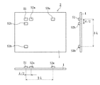
図2は、アレイセンサ2の構成を説明する図である。アレイセンサ2は、基板1上の左右方向に第1センサS1、第2センサS2a、第3センサS3aを直線状に配列し、これに直交する上下方向にも第1センサS1、第2センサS2b、第3センサS3bを直線状に配列している。
FIG. 2 is a diagram for explaining the configuration of the
左右方向に配列したセンサは、音源から発生させる超音波の波長をλとするとき、第2センサS2aを第1センサS1からλ/2の間隔を空けて配置するとともに、第3センサS3aは第1センサS1から3λの間隔を空けて配置している。また、上下方向に配列したセンサについても、第2センサS2bを第1センサS1からλ/2の間隔を空けて配置し、第3センサS3bは第1センサS1から3λの間隔を空けて配置している。 The sensor arranged in the left-right direction arranges the second sensor S2a at an interval of λ / 2 from the first sensor S1 when the wavelength of the ultrasonic wave generated from the sound source is λ, and the third sensor S3a One sensor S1 is arranged at a distance of 3λ. As for the sensors arranged in the vertical direction, the second sensor S2b is arranged with an interval of λ / 2 from the first sensor S1, and the third sensor S3b is arranged with an interval of 3λ from the first sensor S1. ing.
なお、図1では図示していないが、筐体4の上面板40には、センサS2b,S3bが接している部分にも、41,42a,43aと同様の超音波導入孔を設けている。本実施例では、上面板40に超音波導入孔を計5個開口させるとともに、超音波導入孔から筐体内に塵や水が浸入しないように、筐体4の上面板40の上部に超音波透過膜5を取り付けている。この超音波導入孔41,42a,43aと超音波透過膜5の構成の詳細については、後述する。
Although not shown in FIG. 1, the
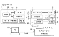
図3は、本実施例の動線計測システムの送信ユニット6と受信ユニットRの構成を説明するブロック図である。本実施例の動線計測システムは、位置検出対象が大型店舗などの建物内で床面の上を移動する移動体(例えばショッピングカートなど)であり、間欠的に超音波を発生可能な音源61を備えた送信ユニット6を移動体に搭載し、一方、音源61から送波された超音波を受波するアレイセンサ2を有する受信ユニットRを例えば店舗の壁や柱、陳列棚、天井面などの定位置に設置し、受信ユニットRに対する音源61の相対位置を求め、移動体の移動状況を追跡し、動線計測を行うものである。
FIG. 3 is a block diagram illustrating the configuration of the transmission unit 6 and the reception unit R of the flow line measurement system of the present embodiment. In the flow line measurement system of the present embodiment, the position detection target is a moving body (for example, a shopping cart) that moves on a floor surface in a building such as a large store, and a
音源61の超音波発生素子は、圧電セラミックス素子である村田製作所製のピエゾタイト(登録商標)を使用している。送信ユニット6は、音源61と、固有の識別情報信号を発信するID送信部62と、これらのドライバを制御する制御部63(マイクロコンピュータ)とを備えている。また、ID送信部62は、光、赤外線、もしくは電波からなり、トリガ信号を発信するトリガ信号発信器の機能も兼ね備えている。音源61からの超音波の送波開始タイミングやID送信部62からの識別情報信号の送信タイミングは、制御部63のマイクロコンピュータに適宜のプログラムを搭載して実行させることにより制御している。
The ultrasonic wave generating element of the
一方、受信ユニットRには、前述したアレイセンサ2と、ID送信部62から送信された識別情報信号を受信するID受信部7と、アンプ8、入力された信号をデジタルデータに変換するADコンバータ部9、これらのドライバを制御する制御部3(マイクロコンピュータ)とを備えている。また、ID受信部7は、ID送信部62から送信されたトリガ信号を受信するトリガ信号受信器の機能も兼ね備えている。本発明では、アレイセンサ2から出力される受波信号を解析する制御部3のマイクロコンピュータに適宜のプログラムを搭載し、第2センサと第1センサの受波時間の差をn×λ/L倍して第3センサの受波時間の予測値を求める予測手段と、第3センサにおいて前記予測値から所定の時間範囲内に検出された受波信号のみを正しい信号として採用する確認手段を実行させるように構成した。なお、確認手段において許容する「所定の時間範囲」は任意に定めることができるが、例えば、予測手段により求めた予測値を基準として前後半波長分の時間範囲内とすることができる。確認手段において許容する時間範囲内に受波信号が検出されなかったときは、正しい受波信号ではないと判断し、エラー処理を行う。
On the other hand, the receiving unit R includes the
本発明の動線計測システムでは、図4に示すように、受信ユニットRを店舗の壁や柱、陳列棚、天井面などの所定位置に複数設置する。そして、各送信ユニット6の音源61の相対位置に関するデータは、受信ユニットRのADコンバータ部9、制御部3を介して所定のデータ列に変換され、さらに、出力部10を介して有線又は無線通信により中継装置11に送られ、最終的にはLAN回線を通じてコンピュータ装置12などの管理装置へ出力される。なお、出力部10は、例えばRS/485のようなシリアル転送方式のインタフェースや、SCSIのようなパラレル転送方式のインタフェースを採用することができる。
In the flow line measurement system of the present invention, as shown in FIG. 4, a plurality of receiving units R are installed at predetermined positions such as store walls, pillars, display shelves, and ceiling surfaces. Data relating to the relative position of the
コンピュータ装置12では、所定時間毎にカートの位置をプロットし、店内における顧客の動線を把握する。本システムを利用すれば、顧客が商品を購入するために店内をどのようなルートで移動したかを時間毎のデータで分析できるので、商品を効率良く販売する最適な商品レイアウトを決定することができる。
The
なお、本実施例では、受信ユニットRを天井面などの定位置に設置し、送信ユニット6を移動体の方に搭載する例を開示しているが、これらは逆であっても良い。本発明は、アレイセンサ2を含む受信センサRの方を移動体に搭載し、音源61を含む送信ユニット6の方を定位置に配置することも可能である。
In addition, although the present Example discloses the example in which the receiving unit R is installed at a fixed position such as a ceiling surface and the transmitting unit 6 is mounted on the moving body, these may be reversed. In the present invention, the receiving sensor R including the
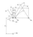
次に、本発明の動線計測システムのデータ処理を説明する。図5は、基板1上に配列された複数のセンサを示しており、本実施例では、左右方向に配列されたセンサS1,S2a間の距離はλ/2、センサS1,S3aの距離は3λとなるよう、また、上下方向に配列されたセンサS1,S2b間の距離はλ/2、センサS1,S3bの距離は3λとなるように各センサが配置されている。
Next, data processing of the flow line measurement system of the present invention will be described. FIG. 5 shows a plurality of sensors arranged on the
いま、図5では、送信ユニット6の音源61からの超音波51,52,53は、センサS1,S2a,S3aが配置された面に対して垂直な方向から角度θ1だけ左側に回転した方向から入射している。音源61までの距離は、各センサ間の距離と比較して十分遠くにあるので、図5において、超音波51〜53はほぼ平行に入射していると考えることができる。また、超音波51,52,53とは別の超音波54,55は、センサS1,S2a,S3aが配置された面に対して垂直な方向から角度θ2だけ右側に回転した方向から入射している。超音波54,55も、ほぼ平行に入射していると考えることができる。
Now, in FIG. 5, the
超音波51〜53は、センサS1,S2a,S3aの配置面に対して入射角θ1の角度で入射するため、超音波53がセンサS3aに到達する時間は、超音波51がセンサS1に到達する時間と比較すると、入射角θに依存した時間だけ遅れることとなる。したがって、各センサの受波時間の差が分かれば、音源がどの方向に存在するか(入射角θの値)を知ることができる。
Since the
図6は、音源61から送波された超音波の入射角θ1を求める本発明の方式を説明する図である。先ず、第1センサS1のノイズレベルよりも十分に高い任意の閾値を設定し、図6(a)に示すように、受波信号がその閾値を上方に越える点をPとする。
FIG. 6 is a diagram for explaining the method of the present invention for obtaining the incident angle θ1 of the ultrasonic wave transmitted from the
本実施例では、センサS1,S2a間の距離をλ/2としている。したがって、θ1,θ2の角度が±50°以内ではP点から半波長以内の位置QにセンサS2aの検出信号が表れる。本発明では、第2センサS2aを第1のセンサS1からλ/2以下の間隔の位置に配置したので、センサの閾値を越える波形を検出したとき、その前後の波形を誤検出するおそれは無く、半波長以内の位置Qに検出される波形は、正しい信号と考えることができる。 In this embodiment, the distance between the sensors S1 and S2a is λ / 2. Therefore, when the angles θ1 and θ2 are within ± 50 °, the detection signal of the sensor S2a appears at a position Q within half a wavelength from the point P. In the present invention, since the second sensor S2a is disposed at a distance of λ / 2 or less from the first sensor S1, there is no possibility of erroneously detecting the preceding and succeeding waveforms when a waveform exceeding the sensor threshold is detected. The waveform detected at the position Q within half a wavelength can be considered as a correct signal.
次に、本実施例では、センサS1,S3a間の距離を3λとしているので、制御部3により、PQ間の時間差TPQの6倍の時間位置Rに、第3センサS3aの受波信号が検出されると予測することができる。そして、制御部3は、第2センサS2aと第1センサS1の受波時間の差を6倍して第3センサS3aの受波時間の予測値を求める予測手段と、第3センサS3aにおいて前記予測値から前後半波長分の時間範囲内に検出された受波信号のみを正しい信号として採用する確認手段を実行する。
Next, in the present embodiment, since the distance between the sensors S1 and S3a is 3λ, the
そして、本実施例では、上記確認手段により正しい信号と確認された第3センサS3aの受波時間に基づいて、音源61から送波された超音波の入射角θ1を求めるようにしている。具体的には、図6におけるPR間の受波時間の差をTPR、音波速度を340m/sとすると、θ1は、以下の計算式で求めることができる。
3λ×sinθ1=340×TPR
sinθ1=(340×TPR)/3λ
θ1=sin-1((340×TPR)/3λ)
In this embodiment, the incident angle θ1 of the ultrasonic wave transmitted from the
3λ × sin θ1 = 340 × T PR
sin θ1 = (340 × T PR ) / 3λ
θ1 = sin −1 ((340 × T PR ) / 3λ)
また、基板1上に上下方向に配列したセンサS1,S2b,S3bの間でも、上記と同様の処理を行うことにより、音源61が存在する方位を二次元的に把握できる。また、マイナス側の角度から入射している超音波54,55の入射角θ2を求める場合についても同様に、上記の式で求めることができる。但し、この場合は、図6に示すように、第1センサS1よりも第2センサS2a、第3センサS3aの方が先に超音波を受波するので、図6のグラフにおいて、Q点とR点は、P点よりも左側の位置に現れることとなる。
Further, by performing the same process as described above between the sensors S1, S2b, and S3b arranged on the
次に、図7〜図8を用いて、超音波導入孔と超音波透過膜のより好適な実施形態について説明する。図7は、基板1に配置された複数のセンサS1,S2a,S3a,S2b,S3b全体が含まれる角型の大きなサイズの超音波導入孔70を、筐体4の上面板40に1つ形成し、その開口部に防塵、防滴用の超音波透過膜5を貼り付けて超音波受信部を構成した第1実施例を示したものである。本発明者らが種々検討したところによると、上記第1実施例では、後述する第2実施例と比較すると、位置検出精度が低下することが判明した。
Next, a more preferred embodiment of the ultrasonic wave introduction hole and the ultrasonic wave permeable membrane will be described with reference to FIGS. FIG. 7 shows that one rectangular large-sized ultrasonic
その原因は、広い面積を有する超音波導入孔70から入ってきた超音波が、図7(b)に図示するように、超音波透過膜5とセンサS1,S2a,S3aを配置している基板1の間を何回か繰返し反射してセンサS1,S2a,S3aに入力してくる状態となり、反射せずに超音波透過膜5から直接入ってきた超音波と複合されることになり、超音波の位相から正しく方位を検出することが出来なくなる場合があるからである。
The cause is that the ultrasonic wave entering from the ultrasonic
そこで、本発明では、図8に示す第2実施例の構成を採用することが最も望ましい。第2実施例では、基板1上に配列されたセンサS1,S2a,S3a,S2b,S3bは、筐体4の上面板40の裏面に接する位置に配置されている。その位置には、図8に示すように、センサS1,S2a,S3a,S2b,S3bの上面部の面積よりもサイズが小さい超音波導入孔81,82a,83a,82b,83bを夫々設けている。
Therefore, in the present invention, it is most desirable to adopt the configuration of the second embodiment shown in FIG. In the second embodiment, the
このように構成すれば、超音波導入孔81,82a,83a,82b,83bは各センサの近傍に個別に形成されるため、他の位置から入力してきた超音波と複合されることがなく、入射位置による超音波位相差を正しく検出することが可能となり精度の良い位置計測が可能となる。 If comprised in this way, since the ultrasonic introduction holes 81, 82a, 83a, 82b, and 83b are individually formed in the vicinity of each sensor, they are not combined with ultrasonic waves input from other positions, It is possible to correctly detect the ultrasonic phase difference due to the incident position, and it is possible to measure the position with high accuracy.
第2実施例の構成とした場合、外部の任意の方向から超音波導入孔を覗くと、内部にあるセンサが完全には見えない状態となるが、超音波は回り込みにより各センサに到達するので、実用上問題はない。また、超音波導入孔81,82a,83a,82b,83bのサイズは全て等しくしているので、回り込みにより各センサに到達する経路も等しいと考えることができるので、精度上も問題がない。 In the case of the configuration of the second embodiment, when looking into the ultrasonic wave introduction hole from any external direction, the internal sensor becomes completely invisible, but the ultrasonic wave reaches each sensor by wraparound. There is no practical problem. Further, since the sizes of the ultrasonic introduction holes 81, 82a, 83a, 82b, and 83b are all equal, it can be considered that the paths reaching each sensor by wraparound are equal, so there is no problem in accuracy.
超音波導入孔81,82a,83a,82b,83bの形状は、角型、丸型等、所望の形状が可能である。また、本発明者らが種々検討したところによると、例えば40KHzの超音波を使用する場合、辺長または直径は1〜4mmの範囲とすることが望ましいことが判明している。超音波導入孔の辺長または直径の設計の目安は、超音波の周波数によっても変わるが、超音波の波長をλとすると、空気中では1mm以上でλ/2mm以下の範囲とするのが好適である。超音波の周波数を40KHz、音速を340m/sとすると、波長λはおよそ8mmであることから、この場合、辺長または直径は1〜4mmの範囲とすることが望ましい。 The ultrasonic introduction holes 81, 82a, 83a, 82b, and 83b can have a desired shape such as a square shape or a round shape. Further, according to various studies by the present inventors, it has been found that, for example, when using an ultrasonic wave of 40 KHz, the side length or the diameter is preferably in the range of 1 to 4 mm. The guideline for designing the side length or diameter of the ultrasonic introduction hole varies depending on the frequency of the ultrasonic wave. However, when the wavelength of the ultrasonic wave is λ, it is preferable that the range is 1 mm or more and λ / 2 mm or less in the air. It is. If the ultrasonic frequency is 40 KHz and the sound speed is 340 m / s, the wavelength λ is about 8 mm. In this case, the side length or diameter is preferably in the range of 1 to 4 mm.
超音波透過膜5は、例えばポリエチレンテレフタレート製の膜を使用し、膜厚は1μm以上で6μm以下の範囲とすることが望ましい。この1〜6μmの範囲とすれば、超音波が透過したときでも減衰が小さく、実用上好ましいからである。
As the
以上説明したように、本発明の動線計測システムは、アレイセンサの基板上の左右方向とこれに直交する上下方向に第1、第2及び第3センサを夫々直線状に配列し、かつ、前記音源から発生させる超音波の波長をλとするとき、前記第2センサは前記第1センサからλ/2以下の間隔Lで配置するとともに、前記第3センサは前記第1センサからn×λ(nは自然数)の間隔で配置したので、熱励起式の超音波発生素子ではなく、受波信号が徐々に大きくなる圧電式の超音波発生素子を使用した場合でも、受波信号の誤検出を可及的に防止することができる。 As described above, the flow line measurement system of the present invention has the first, second, and third sensors arranged linearly in the left-right direction on the substrate of the array sensor and the vertical direction orthogonal thereto, and When the wavelength of the ultrasonic wave generated from the sound source is λ, the second sensor is arranged at an interval L of λ / 2 or less from the first sensor, and the third sensor is n × λ from the first sensor. Since (n is a natural number), the received signal is erroneously detected even when a piezoelectric ultrasonic generator that gradually increases the received signal is used instead of the thermal excitation ultrasonic generator. Can be prevented as much as possible.
また、基板と、アレイセンサと、制御部を格納する筐体を有し、第1、第2及び第3センサは前記筐体の上面板の裏面に接する位置に配置するとともに、当該配置位置には前記第1、第2及び第3センサの上面部の面積よりもサイズが小さい超音波導入孔を夫々設け、さらに、前記超音波導入孔の上面を覆う超音波透過膜を取り付けた構成の動線計測システムによれば、防塵、防滴の目的でセンサを保護する超音波透過膜を取り付けた場合でも、入射位置による超音波位相差を正しく検出することが可能となり精度良く位置計測が可能となるので、さらに好適な効果が得られる。 In addition, a housing for storing the substrate, the array sensor, and the control unit is provided, and the first, second, and third sensors are disposed at a position in contact with the back surface of the upper surface plate of the housing, and at the disposed position. Is provided with ultrasonic introduction holes each having a size smaller than the area of the upper surface of the first, second, and third sensors, and an ultrasonic transmission film that covers the upper surface of the ultrasonic introduction holes. According to the line measurement system, even when an ultrasonic transmission membrane that protects the sensor for dustproof and dripproof purposes is attached, it is possible to correctly detect the ultrasonic phase difference depending on the incident position, and to measure the position accurately. Therefore, a more preferable effect can be obtained.
本発明は上記の実施例に限らず、各請求項に記載された技術的思想の範囲内で、適宜実施の形態を変更しても良いことはいうまでもない。例えば、超音波導入孔の形状は実施例に示した丸型に限らず、角型であっても良い。 The present invention is not limited to the above-described embodiments, and it is needless to say that the embodiments may be appropriately changed within the scope of the technical idea described in each claim. For example, the shape of the ultrasonic wave introduction hole is not limited to the round shape shown in the embodiment, and may be a square shape.
本発明は、ショッピングカートなどに取り付けて顧客の動線分析をするシステムに限らず、例えば、倉庫に保管してある部品や機器に超音波タグ(送信ユニット)を貼り付け、タグから間欠的に超音波とID信号を送信し、それらを受信ユニットで受信することにより、部品や機器の存在位置をリアルタイムで確認するシステムにも適用できる。また、人に超音波タグ(送信ユニット)を持たせ、人の現在位置を検出することにより、高齢者や障害者の徘徊行動を保護者に知らせる報知サービスなどにも適用できる。 The present invention is not limited to a system for analyzing the flow of a customer by attaching it to a shopping cart or the like. For example, an ultrasonic tag (transmission unit) is pasted on a part or device stored in a warehouse, and intermittently from the tag. The present invention can also be applied to a system for confirming the location of components and devices in real time by transmitting ultrasonic waves and ID signals and receiving them by a receiving unit. Moreover, it is applicable also to the alerting | reporting service etc. which notify a guardian of elderly person and a disabled person by giving a person an ultrasonic tag (transmission unit) and detecting a person's present position.
S1 第1センサ
S2a,S2b 第2センサ
S3a,S3b 第3センサ
1 基板
2 アレイセンサ
3 制御部
4 筐体
40 上面板
41,42a,43a 超音波導入孔
5 超音波透過膜
6 送信ユニット
61 音源
81,82a,83a,82b,83b 超音波導入孔
R 受信ユニット
S1 1st sensor S2a, S2b 2nd sensor S3a,
Claims (4)
前記アレイセンサは、前記基板上の左右方向とこれに直交する上下方向に第1、第2及び第3センサを夫々直線状に配列し、かつ、前記音源から発生させる超音波の波長をλとするとき、前記第2センサは前記第1センサからλ/2以下の間隔Lで配置するとともに、前記第3センサは前記第1センサからn×λ(nは自然数)の間隔で配置し、
前記制御部は、前記第2センサと前記第1センサの受波時間の差をn×λ/L倍して前記第3センサの受波時間の予測値を求める予測手段と、前記第3センサにおいて前記予測値から所定の時間範囲内に検出された受波信号のみを正しい信号として採用する確認手段とを備え、
前記確認手段により正しい信号と確認された第3センサの受波信号の受波時間と前記第1センサの受波時間の差と、前記第1、第3センサ間の距離に基づいて、前記音源から送波された超音波の入射角を求め、前記移動体の位置情報を検出することを特徴とする動線計測システム。 An array sensor in which a sound source capable of generating an ultrasonic wave and a plurality of sensors that receive the ultrasonic wave transmitted from the sound source and convert it into a received signal that is an electric signal are two-dimensionally arranged on the same substrate And a control unit that analyzes the received signal, a flow line measuring system in which one of the sound source and the array sensor is mounted on a position detection target moving body, and the other is disposed at a predetermined position. Because
In the array sensor, first, second, and third sensors are linearly arranged in a horizontal direction on the substrate and a vertical direction perpendicular thereto, and the wavelength of the ultrasonic wave generated from the sound source is λ. The second sensor is arranged at an interval L of λ / 2 or less from the first sensor, and the third sensor is arranged at an interval of n × λ (n is a natural number) from the first sensor,
The control unit is configured to calculate a predicted value of the reception time of the third sensor by multiplying a difference between reception times of the second sensor and the first sensor by n × λ / L, and the third sensor And a confirmation means that adopts only a received signal detected within a predetermined time range from the predicted value as a correct signal,
The sound source is based on the difference between the reception time of the reception signal of the third sensor and the reception time of the first sensor, which is confirmed as a correct signal by the confirmation means, and the distance between the first and third sensors. A flow line measurement system characterized in that an incident angle of an ultrasonic wave transmitted from the vehicle is obtained and position information of the moving body is detected.
Priority Applications (1)
| Application Number | Priority Date | Filing Date | Title |
|---|---|---|---|
| JP2008221825A JP5271638B2 (en) | 2008-08-29 | 2008-08-29 | Flow line measurement system |
Applications Claiming Priority (1)
| Application Number | Priority Date | Filing Date | Title |
|---|---|---|---|
| JP2008221825A JP5271638B2 (en) | 2008-08-29 | 2008-08-29 | Flow line measurement system |
Publications (2)
| Publication Number | Publication Date |
|---|---|
| JP2010054439A true JP2010054439A (en) | 2010-03-11 |
| JP5271638B2 JP5271638B2 (en) | 2013-08-21 |
Family
ID=42070515
Family Applications (1)
| Application Number | Title | Priority Date | Filing Date |
|---|---|---|---|
| JP2008221825A Active JP5271638B2 (en) | 2008-08-29 | 2008-08-29 | Flow line measurement system |
Country Status (1)
| Country | Link |
|---|---|
| JP (1) | JP5271638B2 (en) |
Cited By (1)
| Publication number | Priority date | Publication date | Assignee | Title |
|---|---|---|---|---|
| JP2021117209A (en) * | 2020-01-29 | 2021-08-10 | Jfeスチール株式会社 | Method and system for positioning |
Citations (7)
| Publication number | Priority date | Publication date | Assignee | Title |
|---|---|---|---|---|
| JPH04295786A (en) * | 1991-03-26 | 1992-10-20 | Mitsubishi Electric Corp | Laser distance meter |
| JP2000506971A (en) * | 1996-03-07 | 2000-06-06 | スペクトラ プレシジョン アーベー | Electronic distance measuring instrument |
| JP2005051688A (en) * | 2003-07-31 | 2005-02-24 | Matsushita Electric Works Ltd | Ultrasonic array sensor and manufacturing method thereof |
| JP2007085866A (en) * | 2005-09-21 | 2007-04-05 | Osaka Prefecture | Object detection device |
| JP2007333656A (en) * | 2006-06-16 | 2007-12-27 | Murata Mfg Co Ltd | Radar device |
| JP2008070161A (en) * | 2006-09-12 | 2008-03-27 | Denso Corp | Ultraviolet ray detecting device |
| JP2008180593A (en) * | 2007-01-24 | 2008-08-07 | Matsushita Electric Works Ltd | Distance change observation device |
-
2008
- 2008-08-29 JP JP2008221825A patent/JP5271638B2/en active Active
Patent Citations (7)
| Publication number | Priority date | Publication date | Assignee | Title |
|---|---|---|---|---|
| JPH04295786A (en) * | 1991-03-26 | 1992-10-20 | Mitsubishi Electric Corp | Laser distance meter |
| JP2000506971A (en) * | 1996-03-07 | 2000-06-06 | スペクトラ プレシジョン アーベー | Electronic distance measuring instrument |
| JP2005051688A (en) * | 2003-07-31 | 2005-02-24 | Matsushita Electric Works Ltd | Ultrasonic array sensor and manufacturing method thereof |
| JP2007085866A (en) * | 2005-09-21 | 2007-04-05 | Osaka Prefecture | Object detection device |
| JP2007333656A (en) * | 2006-06-16 | 2007-12-27 | Murata Mfg Co Ltd | Radar device |
| JP2008070161A (en) * | 2006-09-12 | 2008-03-27 | Denso Corp | Ultraviolet ray detecting device |
| JP2008180593A (en) * | 2007-01-24 | 2008-08-07 | Matsushita Electric Works Ltd | Distance change observation device |
Cited By (2)
| Publication number | Priority date | Publication date | Assignee | Title |
|---|---|---|---|---|
| JP2021117209A (en) * | 2020-01-29 | 2021-08-10 | Jfeスチール株式会社 | Method and system for positioning |
| JP7276182B2 (en) | 2020-01-29 | 2023-05-18 | Jfeスチール株式会社 | Positioning method and positioning system |
Also Published As
| Publication number | Publication date |
|---|---|
| JP5271638B2 (en) | 2013-08-21 |
Similar Documents
| Publication | Publication Date | Title |
|---|---|---|
| EP3044554B1 (en) | Fibre optic cable for a distributed acoustic sensing system | |
| HRP20200313T1 (en) | Method for the remote detection, localization and monitoring of critical faults in pipelines | |
| US9103908B2 (en) | Security monitoring system using beamforming acoustic imaging and method using the same | |
| US7533578B2 (en) | Triangulation with co-located sensors | |
| CA3011922A1 (en) | Range-finding and object-positioning systems and methods using same | |
| US20140376334A1 (en) | Acoustic monitoring system and a method of acoustic monitoring | |
| JP5271638B2 (en) | Flow line measurement system | |
| JP2010038626A (en) | Ultrasonic object direction detection apparatus | |
| JP2008107251A (en) | Position detecting system | |
| KR102263722B1 (en) | Nosie detecting device of ultrasonic sensor for vehicle and noise detecting method thereof | |
| JP2006220642A (en) | Position detecting system | |
| JP2007085866A (en) | Object detection device | |
| EP1531339A3 (en) | Method of passive determination of target data | |
| JP5513706B2 (en) | Position detection system | |
| JP2002131426A (en) | Ultrasonic sensor device | |
| Stancovici et al. | Relative positioning system using inter-robot ultrasonic localization turret | |
| JP5390745B2 (en) | Orientation detection system | |
| JP5390744B2 (en) | Position detection system | |
| JP4089710B2 (en) | Position detection system | |
| JP4100415B2 (en) | Position detection system | |
| JP4569564B2 (en) | Flow line measurement system | |
| JP2008286622A (en) | Ultrasonic measuring device and ultrasonic measuring method | |
| JP4089709B2 (en) | Position detection system | |
| JP4569586B2 (en) | Flow line measurement system | |
| JP4984638B2 (en) | Multistatic sonar and display method thereof |
Legal Events
| Date | Code | Title | Description |
|---|---|---|---|
| A521 | Request for written amendment filed |
Free format text: JAPANESE INTERMEDIATE CODE: A523 Effective date: 20110331 |
|
| A621 | Written request for application examination |
Free format text: JAPANESE INTERMEDIATE CODE: A621 Effective date: 20110331 |
|
| A977 | Report on retrieval |
Free format text: JAPANESE INTERMEDIATE CODE: A971007 Effective date: 20120621 |
|
| A131 | Notification of reasons for refusal |
Free format text: JAPANESE INTERMEDIATE CODE: A131 Effective date: 20120731 |
|
| A521 | Request for written amendment filed |
Free format text: JAPANESE INTERMEDIATE CODE: A523 Effective date: 20120926 |
|
| TRDD | Decision of grant or rejection written | ||
| A01 | Written decision to grant a patent or to grant a registration (utility model) |
Free format text: JAPANESE INTERMEDIATE CODE: A01 Effective date: 20130425 |
|
| A61 | First payment of annual fees (during grant procedure) |
Free format text: JAPANESE INTERMEDIATE CODE: A61 Effective date: 20130513 |
|
| R150 | Certificate of patent or registration of utility model |
Free format text: JAPANESE INTERMEDIATE CODE: R150 Ref document number: 5271638 Country of ref document: JP Free format text: JAPANESE INTERMEDIATE CODE: R150 |
|
| R250 | Receipt of annual fees |
Free format text: JAPANESE INTERMEDIATE CODE: R250 |
|
| R250 | Receipt of annual fees |
Free format text: JAPANESE INTERMEDIATE CODE: R250 |
|
| S531 | Written request for registration of change of domicile |
Free format text: JAPANESE INTERMEDIATE CODE: R313531 |
|
| R350 | Written notification of registration of transfer |
Free format text: JAPANESE INTERMEDIATE CODE: R350 |
|
| R250 | Receipt of annual fees |
Free format text: JAPANESE INTERMEDIATE CODE: R250 |
|
| R250 | Receipt of annual fees |
Free format text: JAPANESE INTERMEDIATE CODE: R250 |
|
| R250 | Receipt of annual fees |
Free format text: JAPANESE INTERMEDIATE CODE: R250 |
|
| R250 | Receipt of annual fees |
Free format text: JAPANESE INTERMEDIATE CODE: R250 |
|
| R250 | Receipt of annual fees |
Free format text: JAPANESE INTERMEDIATE CODE: R250 |
|
| R250 | Receipt of annual fees |
Free format text: JAPANESE INTERMEDIATE CODE: R250 |